

Dell PowerVault 136T LTO-SDLT User Manual

Selected Indicators and Controls
Veuillez vous référer au CD-ROM du Guide de l'utilisateur de la Bibliothèque PV -136T pour obtenir une version de ce
Guide de démarrage rapide en anglais, allemand, espagnol, japonais, coréens ou chinois simplifié.
Beziehen Sie sich auf die Handbuch-CD-Rom der PV-136T Bibliothek, um dieses Schnellstart -Handbuch auf
französisch, deutsch, spanisch, japanisch, koreanisch oder in vereinfachtem chinesisch zu lesen.
Favor de consultar el CD-ROM de la Guía del Usuario de la Biblioteca PV-136T para ver esta Guía de Rápido Inicio
en francés, alemán, español, japonés, coreano, o chino simplificado.
TM
Dell PowerVault
TM
*
ONLINE
Online/
Offline...
LCD Display: The LCD display on the Operator Panel is divided
into four discrete areas: leftmost, upper center, rightmost, and lower
center.
Status
Operator Panel
Command
*
*
*
*
*
More
Keypad
136T Library
Quick Start Guide
Leftmost: This area of the display provides constant status about
the Mailbox.
Upper center: This area of the display provides informational,
status, and attention messages.
Rightmost: This area of the display provides constant status about
the drives.
Lower center: This area of the display is comprised of 6 lines of 20
characters per line and provides text and graphics to communicate
interactive dialogs, special messages, alerts, and library
configurations.
Refer to the Operation section of the PowerVault 136T Library
User’s Guide for complete descriptions of special symbols and
messages that can be displayed on the Operator Panel.
Please visit support.dell.com for the latest OS drivers and patches for
the PowerVault 136T Library.
Follow the steps in this guide to quickly get started using
your PowerVault 136T Library
Please refer to the PV-136T Library User's Guide CD-ROM to view this Quick Start Guide in French, German, Spanish,
Japanese, Korean, or Simplified Chinese.
Part Number 2E741
62-2227-01 Rev B
Prior to performing the steps below, it is assumed that the proper
SCSI adapter is installed with all of the appropriate drivers.
6
Connect AC line cord to PowerVault 136T Library, then
Press main power switch on rear panel to ON position.
12
to AC outlet.
1
2
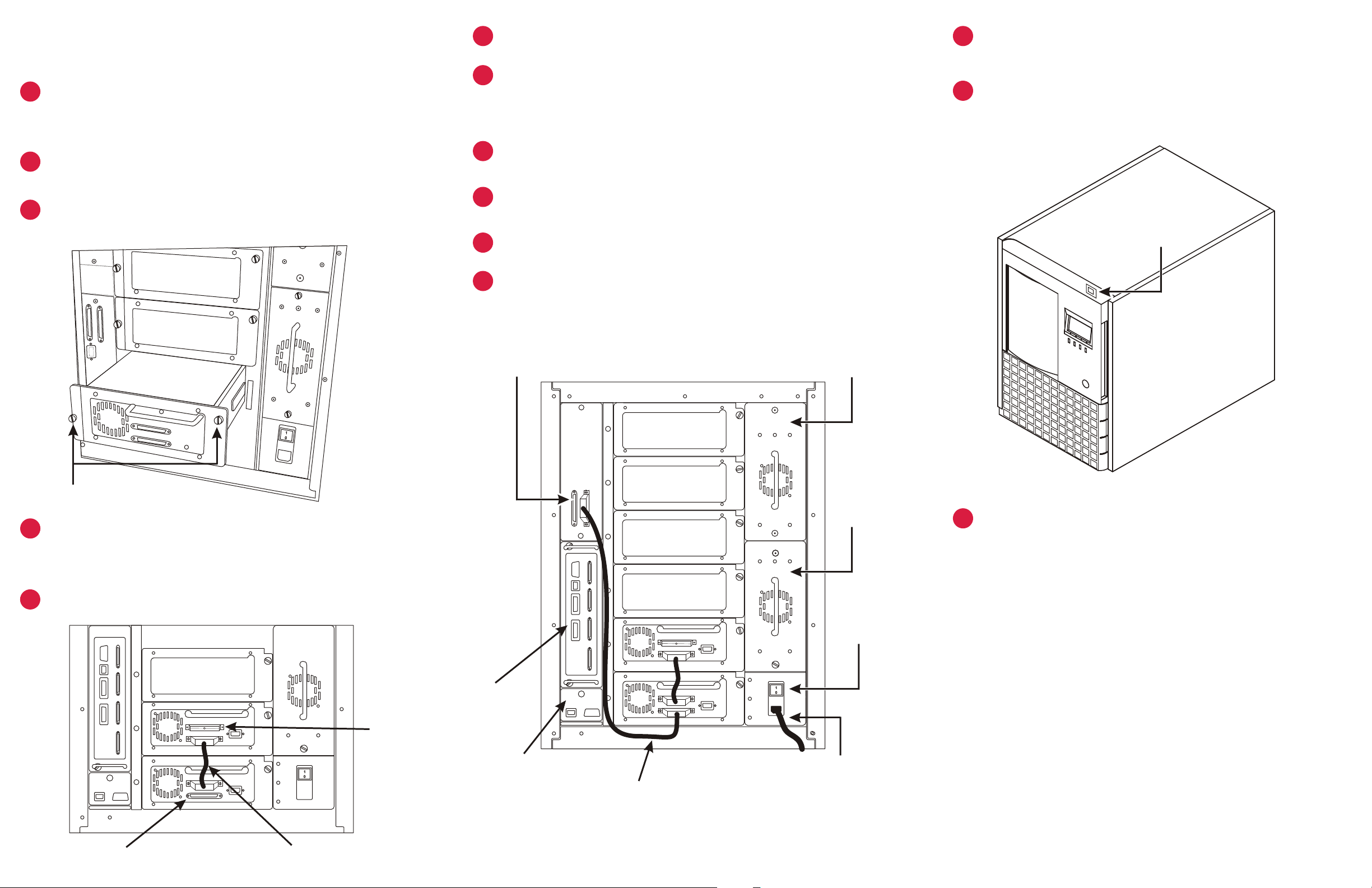
If your PowerVault 136T Library does not have factory
installed drive(s), loosen thumbscrews on empty drive bay
filler plate(s) and pull plate(s) from chassis.
Beginning with the bottom slot, install drive module(s) in empty
8
7
Install SCSI cables between the bottom drive and the library, and
between the host HBA and library. If the Dell PowerVault 136T
Fibre Channel Bridge is being used, refer to the Dell PowerVault
136T Fibre Channel Bridge User’s Guide for cabling instructions.
Remove key from rear panel of PowerVault 136T Library.
Unlock and open front door.PowerVault 136T Library
Press power switch on front panel to power up your
13
PowerVault 136T Library.
drive bay(s).
3
Tighten thumbscrews on drive module(s).
10
11
Filler Plate
Library LVD SCSI Connectors
Drive Module
9
Remove interior packing or securing material from the library to
allow the picker movement.
Install magazines.tape cartridges into
Close and lock front door.
to Host SCSI HBA
Optional Secondary
Power Supply
Power Switch
Captive thumbscrews
Connect the drive modules by inserting one end of a jumper
4
cable into the top SCSI connector of the bottom drive, and the
other end into the bottom SCSI connector of the top drive.
Install SCSI terminator on last device of SCSI chain.
5
Terminator
Fibre Channel
Bridge
Remote
Management Unit
Library SCSI
to Drive
Primary
Power Supply
Main Power
Switch
AC input module
and power cord
Power up your Host computer and verify SCSI communication
14
with all devices on bus.
Your PowerVault 136T Library is now ready to perform
a backup or restore operation via your Host Computer and
backup software.
Drive SCSI
Connectors
Jumper Cable
 Loading...