

Page 1

Dell™ PowerVault™ Systems
Performance Considerations
for Tape Drives and Libraries
www.dell.com | support.dell.com
Page 2

____________________
Information in this document is subject to change without notice.
© 2005 Dell Inc. All rights reserved.
Reproduction in any manner whatsoever without the written permission of Dell Inc. is strictly forbidden.
Trademarks used in this text: Dell, the DELL logo, and PowerVault are trademarks of Dell Inc.; EMC and PowerPath are registered trademarks
of EMC Corporation.
Other trademarks and trade names may be used in this document to refer to either the entities claiming the marks and names or their products.
Dell Inc. disclaims any proprietary interest in trademarks and trade names other than its own.
June 2005
Page 3

Contents
Introduction . . . . . . . . . . . . . . . . . . . . . . . . . . . . . . . . . . . . 5
General Host Backup Considerations
Tape Drive and Data Considerations
Hard Drive and RAID Array Configuration
General Performance Considerations When Using Multiple Drives
in Tape Libraries
SCSI Configurations
SAN Configurations
. . . . . . . . . . . . . . . . . . . . . . . . . . . . . . . . . 12
. . . . . . . . . . . . . . . . . . . . . . . . . . . . . 12
. . . . . . . . . . . . . . . . . . . . . . . . . . . . . 13
. . . . . . . . . . . . . . . . . . . . . . . 5
. . . . . . . . . . . . . . . . . . . . . 5
. . . . . . . . . . . . . . . . . . 6
Contents 3
Page 4

4 Contents
Page 5

Introduction
W
ith recent improvements in tape drive transfer rates, many host-side factors, such as RAID
(Redundant Array of Inexpensive [or Independent] Disks) configuration and hard-drive
specifications, must be considered when determining whether the host server and tape drive can
process data at the same rate. General configurations and attributes that may limit throughput
from the host server to the tape drive are discussed in "General Host Backup Considerations."
As multiple drives are placed into tape libraries, greater host bandwidths are needed to keep pace
with the potential throughput of multiple tape drives. Potential fibre limitations for multidrive
units, as well as recommended cabling configurations, are discussed in "General Performance
Considerations When Using Multiple Drives in Tape Libraries."
General Host Backup Considerations
The considerations in this section apply to both SCSI and storage area network (SAN) tape backup
configurations.
Tape Drive and Data Considerations
The following issues should be considered when evaluating performance:
Overhead from SCSI commands.
in achieving theoretical maximum transfer speeds. Tape backup software does not account for this
overhead; instead, the software only measures the rate at which data is written to the tape. For
example, the drive may be processing 80 MB/sec of data, but only writing 77 MB/sec of data.
The latter rate is what the backup software will report.
Tape block sizes.
applications allow the user to change block size, even though a larger size will not enhance
performance. Using block sizes less than 64 Kb can actually hinder performance. See your backup
software User's Guide for information on adjusting the block size of your tape device.
Backup software buffer size.
as large as possible. Some applications allow users to change the buffer size, which can help
maintain a steady stream of data to and from the drive and significantly increase transfer rates,
especially of small files. The larger the buffer, the more data it can hold and the less time the disk
spends seeking the data; however, this can affect memory and CPU performance. See your tape
backup application User’s Guide for specific details.
Drivers and firmware.
drivers and firmware installed. Visit
for your Dell PowerVault tape product.
64 Kb block sizes are optimal for most tape drives. However, some backup
Always ensure that the SCSI or fibre controller and tape drive have the latest
Command overhead on the SCSI bus restrict
For optimal backup performance, backup software buffers should be
support.dell.com
to download the latest drivers and firmware
all
SCSI devices
Performance Considerations for Tape Drives and Libraries 5
Page 6

Attach tape drives and hard drives on separate controllers (internal or external) on separate host
bus adapters (HBAs).
but best practice is to keep the tape drive HBA separate from the hard drive HBA to ensure
maximum throughput. Most onboard dual-mode SCSI/RAID controllers share one processor,
which must share bandwidth between the RAID array and tape drive. Thus, one controller is
handling reads and writes between the hard disks and the tape drive, as well as calculating and
writing any necessary parity information to the hard drives. See "Hardware RAID Configuration
Considerations" for specific information on RAID arrays and parity bytes.
Dirty drive heads or old media.
a corresponding reduction in read/write speeds. Each time a drive attempts to rewrite or reread a
block on a tape, performance is degraded. Once a certain threshold of read/write errors is reached,
www.dell.com | support.dell.com
the drive will usually request cleaning. It is important to clean the drive heads on regular intervals,
or when requested.
The chance of encountering a bad block increases as media ages or is excessively used. The typical
lifecycle of a piece of LTO media is approximately 75 full tape read/writes.
Speed matching.
down to approximately one-half of the maximum uncompressed data transfer speed. If data is
provided to the drive at less than the lower speed matching limit, the drive must stop, wait for the
buffer to fill, rewind, and then attempt to write the buffer (this is known as "back hitching").
For example, the Dell PowerVault 110T (LTO2 and LTO3) tape drive matches speed down to
30 MB/sec while writing to LTO-3 media. If the host server can only provide data at 20 MB/sec, the
drive will "back hitch" while waiting for its buffers to fill. In this situation, the effective throughput
will be something less than 20 MB/sec (probably closer to 15 MB/sec).
This depends somewhat on the performance capabilities of your controller,
A dirty tape drive head or old media can cause high error rates and
Newer LTO drives will match the speed of the data being provided to the drive,
Confirming Performance of Your Tape Drive
Certain tape drive manufacturers have a performance diagnostic mode built into the drive that can
be used to confirm throughput. The PowerVault 110T LTO-2 and LTO-3 (firmware 53
offer a diagnostic mode "F," which performs a quick read/write performance test on the drive and
media. If the performance rate is not within 6 percent of the maximum specified drive speed, the
test fails with an error message. No error message is displayed if the test passes. Consult your tape
drive User’s Manual for specific details on diagnostic mode "F."
NOTICE: Diagnostic mode "F" requires media that can be safely overwritten as part of the diagnostic test.
Do not use media containing critical data. Any data residing on the media used in the diagnostic test will
be lost.
Hard Drive and RAID Array Configuration
Several hard drive and disk array (both internal and external) attributes can affect backup or restore
performance. These attributes, as well as recommended configurations that help achieve
maximum backup and restore speeds, are discussed in the following subsections. If the tape drive’s
sustainable throughput exceeds that of the disk array, then the tape drive’s peak performance will
not be realized.
6 Performance Considerations for Tape Drives and Libraries
XX
or later)
Page 7
General Hard Drive Configuration Considerations
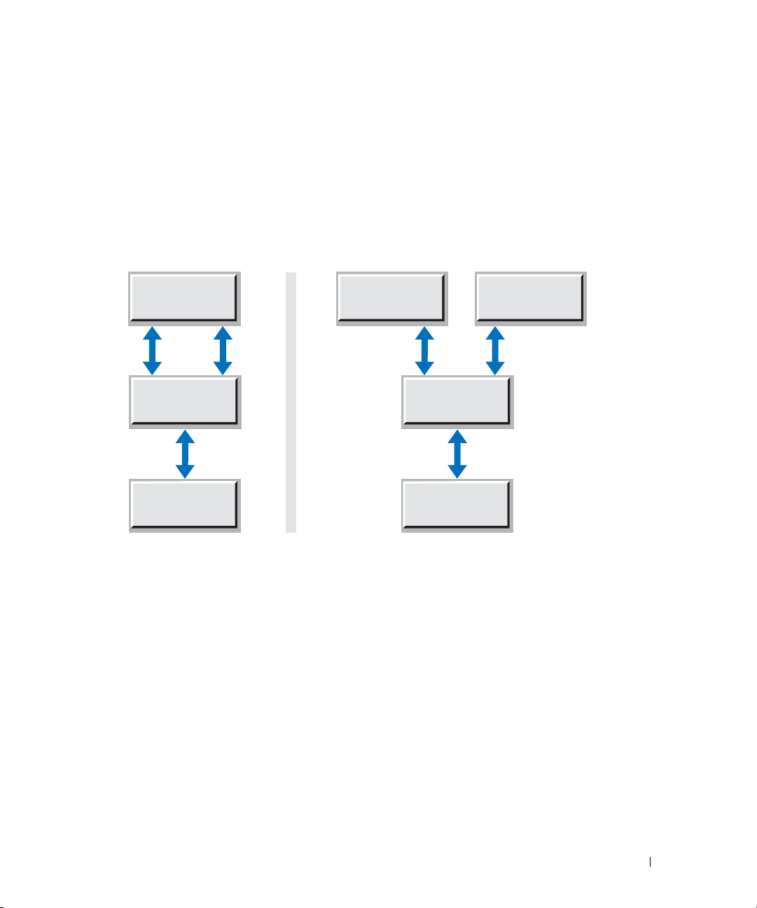
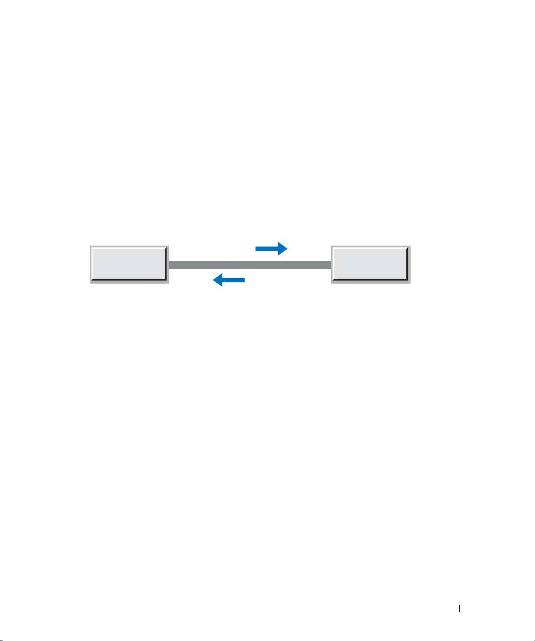
Data/operating system (OS) on different LUNs.
Backing up data on a logical unit number (LUN)
separate from the OS LUN ensures that the hard drive is not splitting access and overhead between
OS operations and backup operations. This can be accomplished by having one hard drive or disk
array contain the OS and a physically separate hard drive or disk array contain the data
to be backed up.
Figure 1-1. Single-Channel vs. Two-Channel Bandwidth
Single Shared LUN Separate LUNs
Single LUN with
Backup data
and OS
OS LUN
Backup Data
LUN
SCSI or RAID
Controller
Tape Drive
Hard Drive Performance
SCSI or RAID
Controller
Tape Drive
By design, tape drives write data sequentially and require a constant data feed to keep the drive
operating sequentially (avoiding back hitching). Conversely, hard drives are random access devices.
Therefore, hard drives can sometimes struggle to provide sequential data to tape drives if that data
is spread out over the drive platter. This forces the drive to continuously seek small blocks of data.
Additionally, other hard drive attributes can further affect the throughput of data to the tape drive.
Spindle speed.
Typically measured in RPMs (revolutions per minute), the hard drive's spindle
speed determines how many times per minute the drive platter assembly can perform a full
revolution. This has a direct effect on both random access times and sequential transfer rates.
The higher the spindle speed, the faster the drive can access data.
Performance Considerations for Tape Drives and Libraries 7
Page 8

Random access time or seek time.
time a drive's heads take to find a piece of data on the disk. The seek time of a hard disk measures
the amount of time required for the read/write heads to move between tracks on the surface of the
platters. Because hard disks are random access devices, data can be stored on virtually any sector of
the disk. The longer it takes to access that data, the slower the overall throughput of the drive. This
attribute is very significant when a hard drive contains many small files. The smaller the files, the
more "seeks" the drive must make to read or write the file to disk; therefore, disks tend to read or
write very slowly when many small files are being transferred.
Sequential/sustained transfer rates (STR).
and writes data to its platters. If the data being backed up is one large contiguous file, the sustained
throughput will be close to the drive's maximum STR. However, in real-world applications, data
www.dell.com | support.dell.com
becomes more scattered about the platter as data is deleted and written. Defragmenting a hard
drive can help the drive reach its maximum STR.
Buffer (cache).
written or stored data. The bigger the buffer, the more data it can hold, resulting in less time
seeking data on the disk.
Hardware RAID Configuration Considerations
General overview of RAID
This section presents an overview of typical RAID configurations and how they affect backup and
restore rates. A RAID array is a set of hard disks that act as a single storage system or LUN. Data can
be potentially transferred through the channel of each hard drive at once, allowing for total
throughput to be a multiple of the total number of drives in the array, minus overhead and any
redundancy as described in the following sections.
In the case of a RAID configuration, the speed of the interface becomes important because the
drives share the bandwidth of the interface. For example, a single Ultra160 drive may only sustain
40 MB/sec. Thus, a five-disk RAID 0 array consisting of the same drive type should be able to
read/write at 200 MB/sec. However, the Ultra160 interface will limit the array to a maximum of
160 MB/sec.
External disk arrays, particularly in SANs, may offer significant levels of cache memory to improve
I/O performance. This cache will greatly improve performance when writing to the array and may
store frequently accessed data to improve read performance. With respect to its impact on tape
performance, the cache will mask most RAID limitations when restoring data to the array or
backing up data from the array. However, backup operations from external arrays with cache may
still feel the impact of RAID configuration limitations because the data still needs to be read from
the disks.
Usually measured in milliseconds, seek time is the length of
STR measures how fast a drive actually reads data from
The buffer is the amount of memory on the drive that holds the most recently
8 Performance Considerations for Tape Drives and Libraries
Page 9
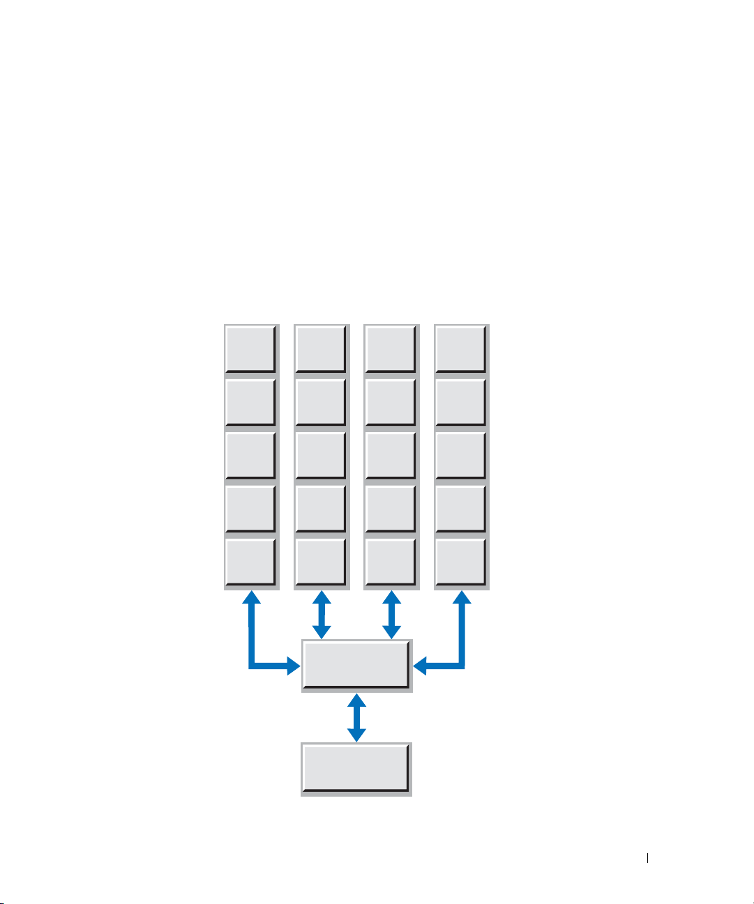
RAID 0
Commonly known as striping, RAID 0 allows two or more disks to be joined to create one virtual
drive in the fashion of a single LUN. It is referred to as striping because data is written across all of
the disks in the array, not just to one disk at a time. Thus, the throughput is spread across
channels (
n
being the number of hard drives in the array) instead of a single channel for a single
n
hard disk. This results in excellent read/write performance, but no fault tolerance.
Figure 1-2 shows four hard drives in a RAID 0 configuration. Data is striped across all four hard
drives, resulting in four channels for reading and writing to the array.
Figure 1-2. Example RAID 0 Configuration
Hard Drive 1 Hard Drive 2 Hard Drive 3 Hard Drive 4
D = Data Byte
D1
D2
D3
D4
D5
D9
D13
D17
D6
D10
D14
D18
SCSI or RAID
Controller
Tape Drive
D7
D11
D15
D19
D8
D12
D16
D20
Performance Considerations for Tape Drives and Libraries 9
Page 10
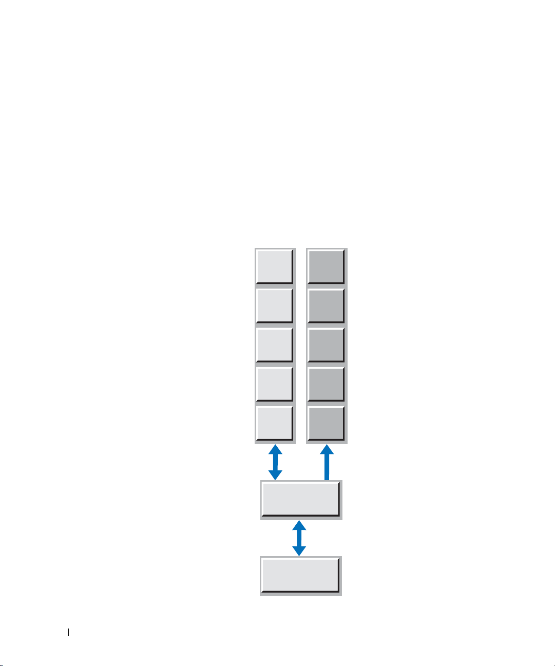
RAID 1
Also known as mirroring, RAID 1 means data is written twice across two disks simultaneously. If
one drive fails, the system switches to the other drive without losing data. During tape drive
backups, the read rate from the RAID 1 array is approximately the same as a single drive because it
is reading from the primary drive. However, restore performance from the tape drive writing to the
RAID 1 array can be slower due to error checking/correction (ECC) included in writing to the
primary and mirrored disks. Much of this inefficiency is due to the fact that the mirroring is often
performed on the CPU or RAID controller. Thus, newer RAID controllers tend to be faster due to
newer and more capable processors.
Figure 1-3. Example RAID 1 Configuration
www.dell.com | support.dell.com
D = Data Byte
M = Mirrored Byte
Hard Drive 1 Hard Drive 2
D1
M1
D2
D3
D4
D5
SCSI or RAID
Controller
Read/Write
Tape Drive
M2
M3
M4
M5
Write OnlyRead/Write
10 Performance Considerations for Tape Drives and Libraries
Page 11
RAID 5
With a RAID 5 array, data is striped across the disk array at the byte level and error correction data,
or parity data, is also striped across the disk array. RAID 5 arrays tend to have very good random
read performance; this read performance generally improves as the number of disks in the array
increases. With the larger disk arrays, read performance can actually outperform RAID 0 arrays
because the data is distributed over an additional drive. In additional, parity information is not
required during normal reads.
Restores from tape to a RAID 5 array tend to be nominal because it involves additional overhead
for calculating and writing the parity information.
Figure 1-4. Example RAID 5 Configuration
Hard Drive 1 Hard Drive 2 Hard Drive 3 Hard Drive 4
P = Parity Byte
D = Data Byte
P1
D1
D2
D3
Read/Write
D4
D7
D10
D13
P2
D8
D11
D14
SCSI or RAID
Controller
Read/Write
Tape Drive
D5
P3
D12
D15
D6
D9
P4
D16
Performance Considerations for Tape Drives and Libraries 11
Page 12

In conclusion, RAID 0 tends to be the best overall configuration for read and write performance,
but does not allow for redundancy. RAID 1 is the worst performer overall, as all data written to
the array is mirrored and reads come from a single disk. RAID 5 tends to be a good read performer
but average write performer; however, RAID 5 improves if more disks are added to the array. If
the RAID is within an enclosure that offers significant levels of cache memory, then performance
limitations during restore operations may be abated. Backup operations will still be subject to
limitations of the RAID configuration.
heavily on the specific hard drive characteristics listed in "Hard Drive Performance."
In addition, the characteristics of the array still depend
General Performance Considerations When Using Multiple
www.dell.com | support.dell.com
When multiple tape drives are utilized simultaneously to perform data backups (such as in tape
libraries), additional aspects of the hardware configuration must be considered. By employing
simple performance-minded methods in setting up hardware and cabling configurations, additional
throughput bottlenecks can be limited.
SCSI Configurations
The latest high-performance tape drives offered in tape libraries support the Ultra160 specification
of the SCSI interface standard. Therefore, to achieve maximum performance, backup servers
utilizing SCSI must have an HBA installed that supports data speeds of Ultra160 or higher. A SCSI
HBA that meets this requirement will allow each tape drive to communicate with the host at a rate
of 160 MB/sec on the SCSI bus. The higher data rate of the SCSI bus compared to tape drive
speeds allows multiple devices to be connected to the same bus without sacrificing device
performance. But only to a point.
The 160 MB/sec data rate of an Ultra160 bus is the maximum possible data throughput rate to all
devices connected to the bus. Therefore, a single tape drive will not consume the full bandwidth of
the bus because it can read or write data to tape at up to 80 MB/sec (native). Multiple tape drives,
however, can combine to consume the full 160 MB/sec offered by the bus if each is operating at its
maximum native performance. Each additional drive connected to the same bus after this point
will reduce the average performance of each drive.
Therefore, to achieve maximum performance from a tape library, it is recommended to connect
no more than two tape drives to each SCSI bus. See "Recommended Cabling Configurations" for
specific details and illustrations. A SCSI HBA supporting at least Ultra160 should be used, but
upgrading to an Ultra320 HBA will not lead to an additional improvement in performance if the
tape drive's specification is Ultra160.
Drives in Tape Libraries
12 Performance Considerations for Tape Drives and Libraries
Page 13
SAN Configurations
Fibre Channel (FC) offers many advantages over SCSI. First, it overcomes the distance limitations
of SCSI (12 meters for LVD SCSI versus 300 meters for a short-wave 2-Gb FC link)
the transmission of data at higher speeds. As a serial network protocol rather than a bus-based
architecture like SCSI, FC has also become the protocol of choice for the implementation of SANs,
allowing for the consolidation of data storage resources. In addition, each FC connection is made
up of a transmit link and a receive link, allowing for full-duplex operation. This means that data can
be transmitted in two directions simultaneously. Therefore, during a backup operation across a
single FC connection, data can be read from a source and written to tape without taking turns in
communication, effectively doubling the bandwidth of a connection. See Figure 1-5.
Figure 1-5. Fibre Channel Link Diagram
2 Gb = 200 MB/sec
and allows for
HOST
Transmit
Receive
Receive
Transmit
2 Gb = 200 MB/sec
Fibre
Channel
Device
When setting up tape libraries in a SAN, performance can still be affected by various factors. These
factors include FC link speeds, data flow between the source and tape library, and performance
limitations of external storage arrays. With an understanding of the overall setup and management
of the solution, many of these factors can be avoided.
Even with the high data bandwidth offered by the FC protocol in SANs, proper considerations
must be made for tape drives in order to avoid a situation in which the FC link may limit
performance. The data rate of a 2-gigabit (Gb) FC link is 200 MB/sec (that is, 200 MB/sec on the
transmit link and 200 MB/sec on the receive link). Therefore, attempting to operate multiple tape
drives across the same link can potentially exceed the full bandwidth of a link. If the host is
operating with a legacy 1-Gb adapter, backing up data to two drives may be sufficient to reveal
significant performance limitations.
Therefore, when using three or more tape drives simultaneously on a 2-Gb link, you may need to
distribute the backups across a number of connections, rather than relying on a single link. This is
where understanding the SAN solution's topology is beneficial. Following the data path during a
backup operation as it is read from the source and then written out to tape will help administrators
recognize any potential bottlenecks. If any bottlenecks are identified, measures may be taken
depending on the configuration. For example, if the backup solution requires multiple drives to be
in operation at once, splitting the tape hardware across separate fabrics may improve performance
by splitting the connections. See Figure 1-6.
Performance Considerations for Tape Drives and Libraries 13
Page 14
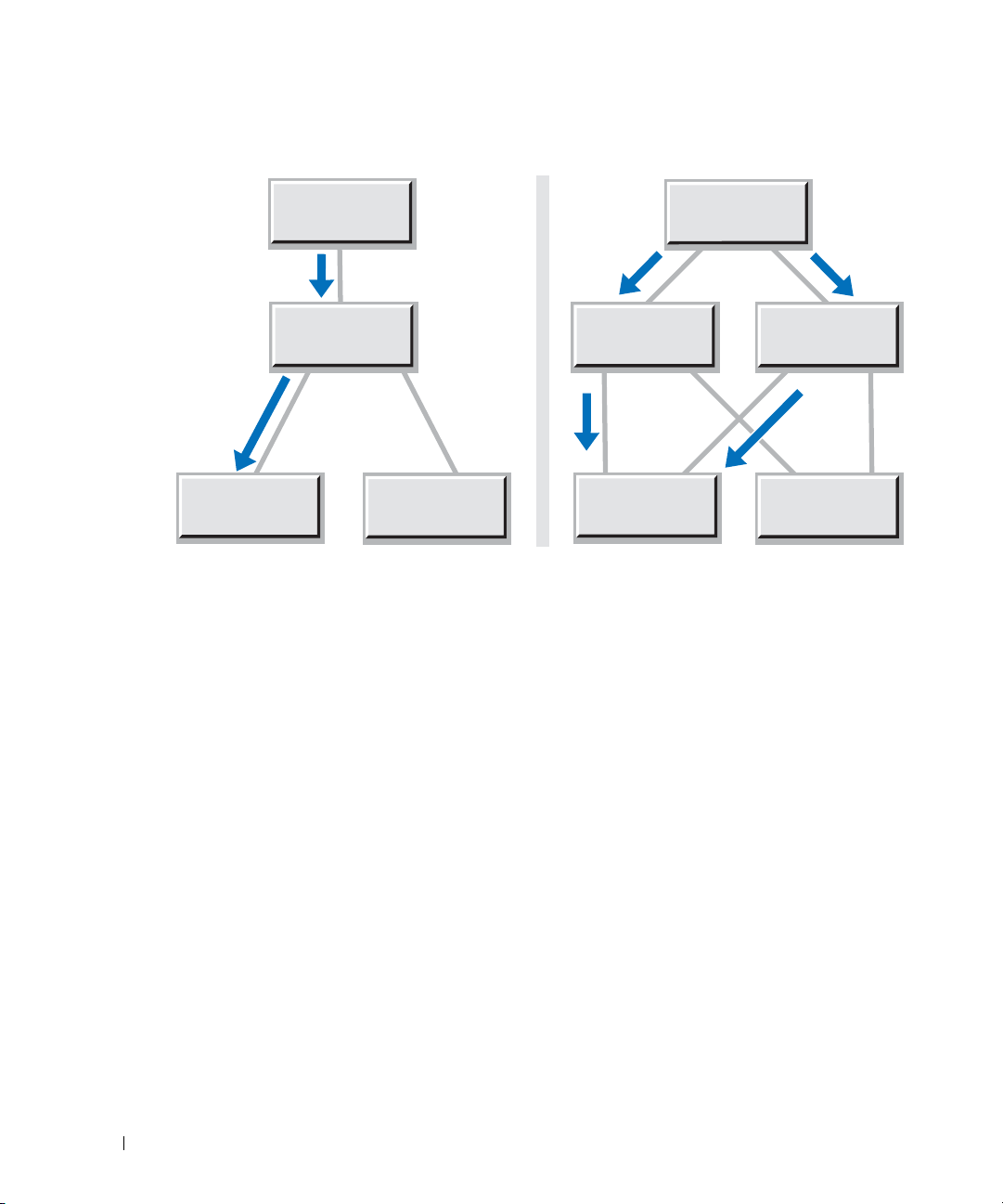
Figure 1-6. Single vs. Split Data Flow to Tape Library
www.dell.com | support.dell.com
Tape Library Tape Library
At the same time, if a bottleneck exists in the data being read from an external FC disk array, the
use of I/O management software such as EMC
will automatically load-balance the data across multiple paths and increase availability through
path failover. See Figure 1-7. The left side of the figure represents a SAN disk array in which all of
the data is forced through a single link, creating a bottleneck that slows data flow to the tape
hardware. The right side shows how load balancing doubles the I/O bandwidth coming out of the
array by allowing the data to transmit across two links.
HOST
Fibre Channel
Switch
Fibre Channel
Disk Array
HOST
Fibre Channel
Switch
®
PowerPath® with an additional fabric connection
Fibre Channel
Switch
Fibre Channel
Disk Array
14 Performance Considerations for Tape Drives and Libraries
Page 15
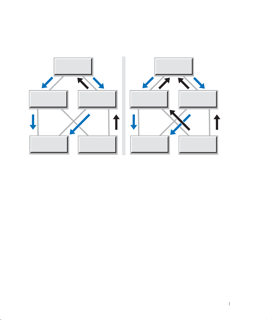
Figure 1-7. Bottlenecked Data Flow vs. Load-Balanced Disk Array
HOST
Fibre Channel
Switch
Tape Library Tape Library
Fibre Channel
Switch
Fibre Channel
Disk Array
Fibre Channel
Switch
HOST
Fibre Channel
Switch
Fibre Channel
Disk Array
Finally, FC disk arrays on the SAN can also experience the same performance limiters described in
"Hard Drive and RAID Array Configuration." Therefore, improving the performance characteristics
of the disk arrays will also have a direct effect on backup speed across the SAN.
SAN Configurations Utilizing the Library Fibre Channel Bridge
Certain tape libraries may be connected to a SAN by way of a Fibre Channel bridge module. The
module acts as a bridge between the SCSI and FC protocols and provides additional management,
security, and operational features unavailable in most native FC libraries. For details on these
features, see the Fibre Channel bridge User's Guide for your tape library.
In some tape library configurations, the Fibre Channel bridge module may act as a bottleneck and
decrease performance of tape drives. This is because the processing capability in the Fibre Channel
bridge module required to bridge the SCSI and FC communication cannot meet the aggregate
data throughput offered by certain multidrive configurations. Despite this, most data backup
solutions will not experience the Fibre Channel bridge module as the primary limiting factor in
tape performance. Dedicated backup servers will frequently encounter a situation where the
limitations at the host will be compounded by the exertion of feeding data to multiple tape drives.
This results in average drive performance below the level where the Fibre Channel bridge module
becomes a factor.
Performance Considerations for Tape Drives and Libraries 15
Page 16
Recommended Cabling Configurations
SCSI Cabling to the Host
Tape Library With up to Six Tape Drives
When the tape library is SCSI-attached to a host, ensure that no more than two drives are on a
single bus. Additional SCSI controllers are required for libraries with five or six tape drives to
ensure that no SCSI bus becomes a barrier to maximizing throughput.
Figure 1-8. SCSI Cabling for Library With up to Six Tape Drives
www.dell.com | support.dell.com
library-to-host
SCSI cable
library-to-host
SCSI cable
drive-to-library
controller SCSI
cable
terminator
terminator
Tape Library With up to Two Tape Drives
The drives in a fully configured two-drive tape library can be cabled to a host on the same SCSI bus
without encountering significant limitations to backup performance. The backup rates for two
drives on a single SCSI bus will match the backup rates for two drives on separate buses. However,
customers who enable the verify feature in backup applications may wish to improve the verify
performance by splitting two drives onto two SCSI buses. By doing so, verify performance may
improve by up to 25 percent.
16 Performance Considerations for Tape Drives and Libraries
Page 17
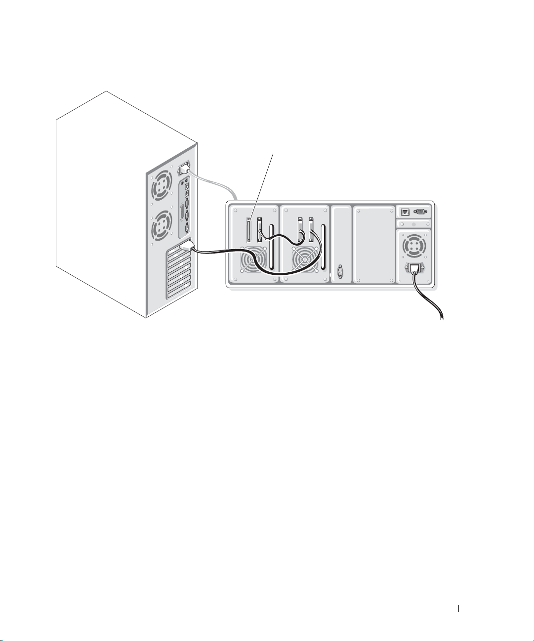
Figure 1-9. SCSI Cabling for Library With up to Two Tape Drives
terminator
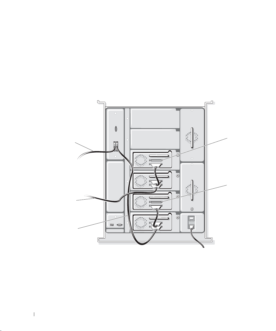
Cabling Drives to the Fibre Channel Bridge
Figures 1-10 through 1-17 illustrate how a tape library with up to six drives should be configured
with a Fibre Channel bridge module in order to optimize tape performance over FC.
Performance Considerations for Tape Drives and Libraries 17
Page 18
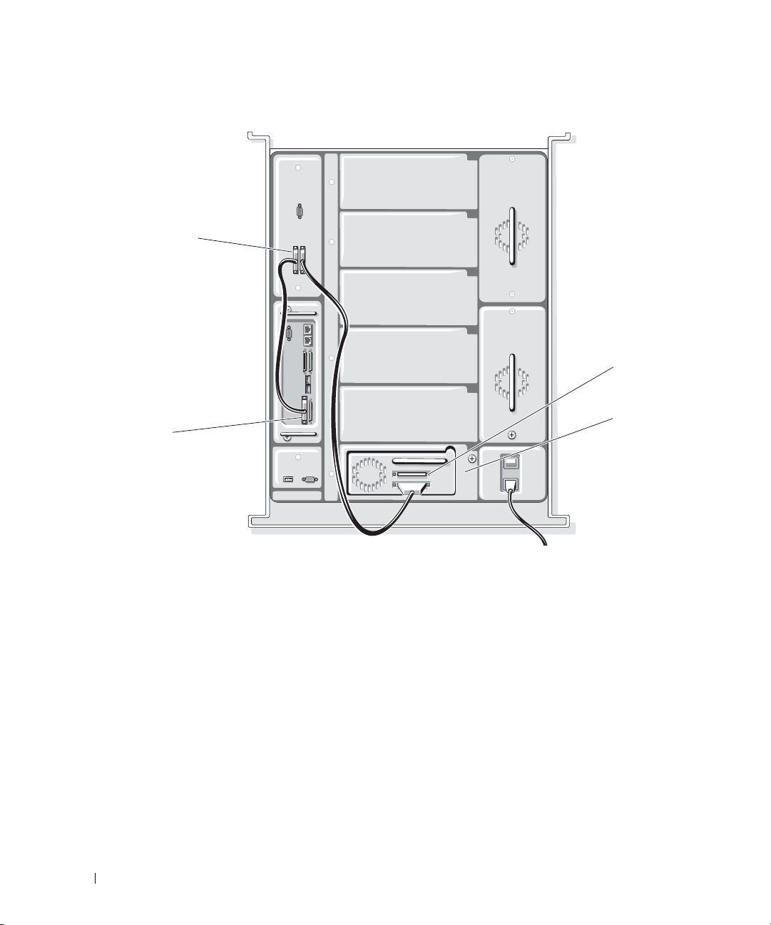
Figure 1-10. Fibre Channel Bridge Cabling With One Tape Drive
library SCSI
interface
www.dell.com | support.dell.com
SCSI 1
terminator
drive 1
18 Performance Considerations for Tape Drives and Libraries
Page 19
Figure 1-11. Fibre Channel Bridge Cabling With Two Tape Drives
library SCSI
interface
SCSI 1
terminator
drive 2
terminator
drive 1
SCSI 2
Performance Considerations for Tape Drives and Libraries 19
Page 20
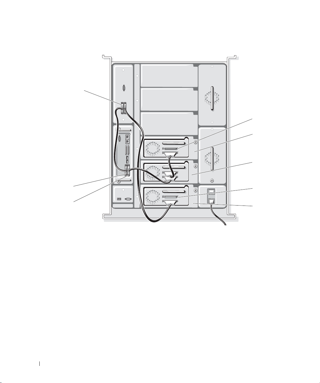
Figure 1-12. Fibre Channel Bridge Cabling With Three Tape Drives
library SCSI
interface
terminator
www.dell.com | support.dell.com
SCSI 1
SCSI 2
drive 3
drive 2
terminator
drive 1
20 Performance Considerations for Tape Drives and Libraries
Page 21
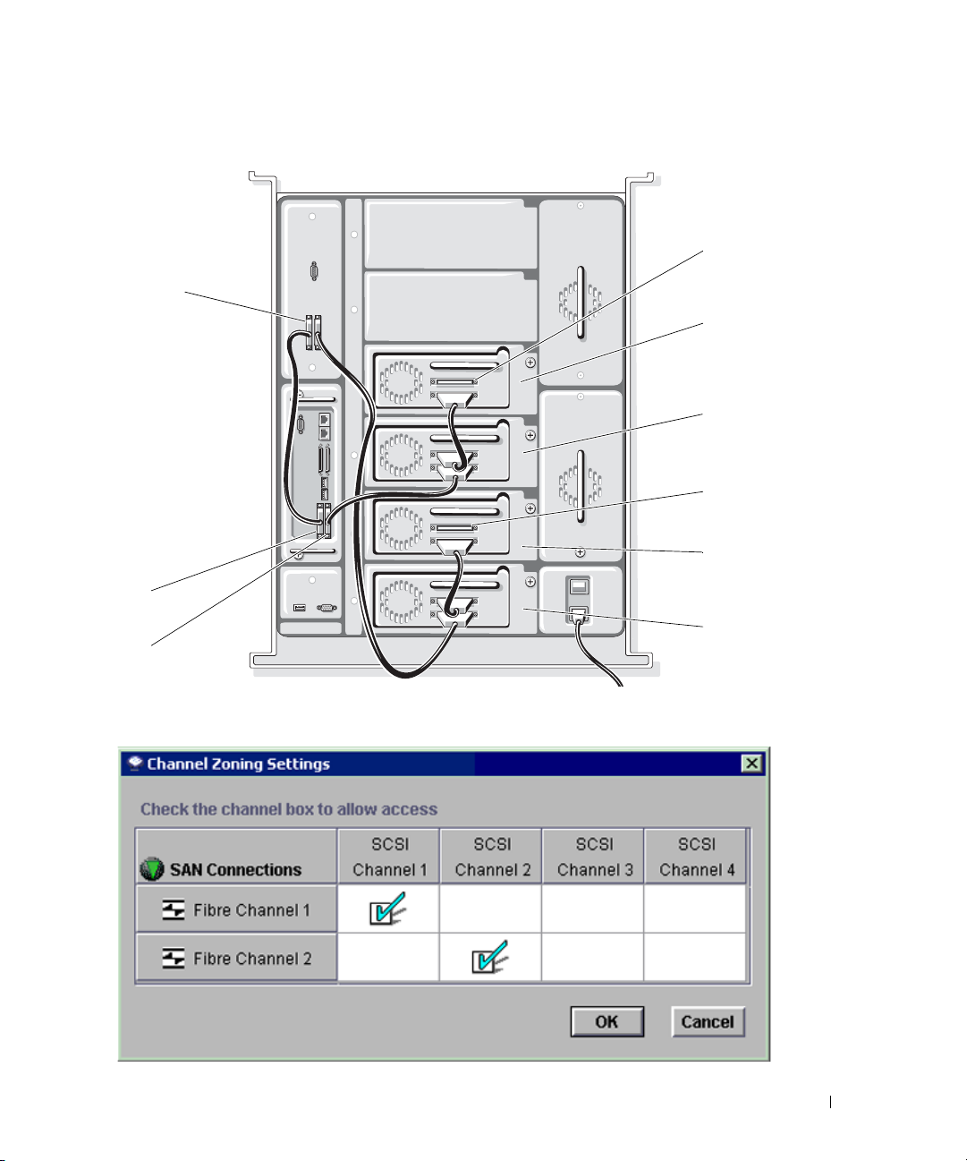
Figure 1-13. Fibre Channel Bridge Cabling With Four Tape Drives
library SCSI
interface
SCSI 1
SCSI 2
terminator
drive 4
drive 3
terminator
drive 2
drive 1
Figure 1-14. Channel Zoning Settings for Tape Library With One to Four Drives
Performance Considerations for Tape Drives and Libraries 21
Page 22
Figure 1-15. Fibre Channel Bridge Cabling With Five Tape Drives
terminator
library SCSI
interface
www.dell.com | support.dell.com
SCSI 3
SCSI 4
SCSI 1
SCSI 2
drive 5
drive 4
terminator
drive 3
drive 2
terminator
drive 1
22 Performance Considerations for Tape Drives and Libraries
Page 23
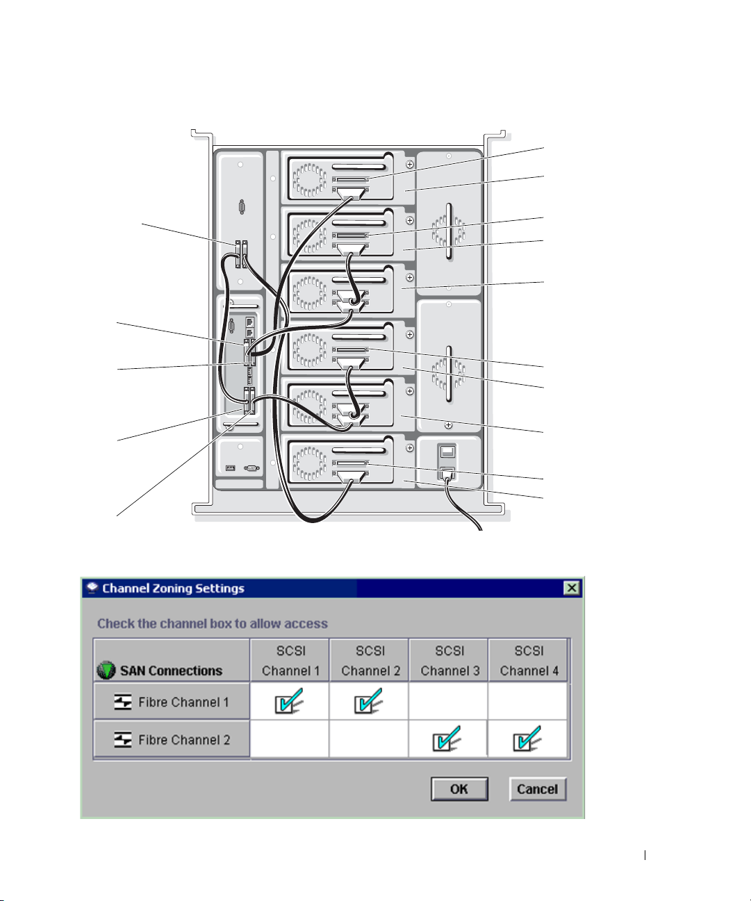
Figure 1-16. Fibre Channel Bridge Cabling With Six Tape Drives
terminator
drive 6
library SCSI
interface
SCSI 3
SCSI 4
SCSI 1
SCSI 2
Figure 1-17. Channel Zoning Settings for Tape Library With Five or Six Drives
terminator
drive 5
drive 4
terminator
drive 3
drive 2
terminator
drive 1
Performance Considerations for Tape Drives and Libraries 23
Page 24
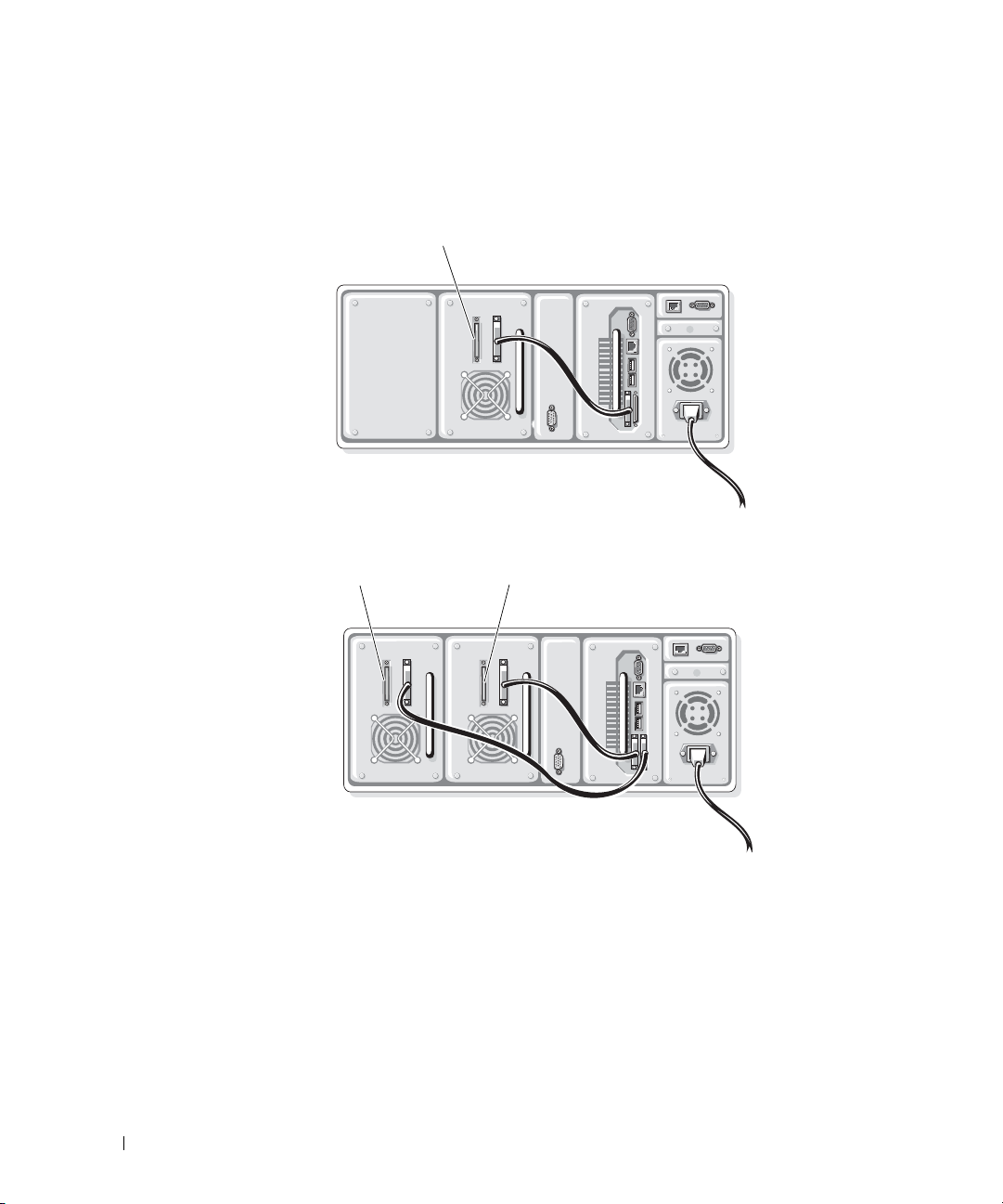
Figure 1-18 and Figure 1-19 illustrate how a tape library with up to two tape drives should be
configured with a Fibre Channel bridge module in order to optimize tape performance over FC.
Figure 1-18. Tape Library With One Drive
www.dell.com | support.dell.com
Figure 1-19. Tape Library With Two Drives
terminator
terminator
terminator
24 Performance Considerations for Tape Drives and Libraries
Page 25

Dell™ PowerVault™ 系统
磁带驱动器和磁带存储库
性能注意事项
www.dell.com | support.dell.com
Page 26

____________________
本文件中的信息如有更改,恕不另行通知。
© 2005 Dell Inc. 版权所有,翻印必究。
未经 Dell Inc. 书面许可,严禁以任何方式进行复制。
本文中使用的商标:Dell、DELL 徽标和 PowerVault 是 Dell Inc. 的商标; EMC 和 PowerPath 是 EMC Corporation 的注册商标。
本文件中述及的其它商标和产品名称是指拥有相应商标和名称的公司或其制造的产品。Dell Inc. 对本公司的商标和产品名称之外
的其它商标和产品名称不拥有任何专有权。
2005 年 6
月
Page 27

目录
简介 . . . . . . . . . . . . . . . . . . . . . . . . . . . . . . . . . . . . . . .
主机备份一般注意事项
磁带驱动器和数据注意事项
硬盘驱动器和 RAID 阵列配置
在磁带存储库中使用多个驱动器时的一般性能注意事项
SCSI 配置
SAN 配置
. . . . . . . . . . . . . . . . . . . . . . . . . . . . . . . . . . 36
. . . . . . . . . . . . . . . . . . . . . . . . . . . . . . . . . . 36
. . . . . . . . . . . . . . . . . . . . . . . . . . . . .
. . . . . . . . . . . . . . . . . . . . . . . 29
. . . . . . . . . . . . . . . . . . . . . . 30
. . . . . . . . .
29
29
36
目录 27
Page 28

28 目录
Page 29

简介
随着近来磁带驱动器传输速率的提高,在确定主机服务器和磁带驱动器能否以相同速率处理
RAID
数据时,必须考虑许多主机方面的因素,如
盘驱动器的规格。在“主机备份一般注意事项”中,将讨论可能会限制从主机服务器到磁带
驱动器吞吐量的一般配置和属性。
由于磁带存储库中放入了多个驱动器,因此,为了满足多个磁带驱动器的潜在吞吐量要求,
需要增加主机带宽。“在磁带存储库中使用多个驱动器时的一般性能注意事项”中将讨论有
关多驱动器单元的潜在光纤限制以及建议的布线配置。
(廉价[或独立]磁盘冗余阵列)配置和硬
主机备份一般注意事项
本节中的注意事项同时适用于
SCSI
和存储区域网络
(SAN)
磁带备份配置。
磁带驱动器和数据注意事项
在评估性能时应考虑以下问题:
SCSI
命令所带来的额外开销。
使之无法获得理论上的最大传输速率。磁带备份软件并未说明这一额外开销,而只是测量数
据写入磁带的速率。例如,驱动器可能以
为
77 MB/
磁带区块大小。对于大多数磁带驱动器,
序允许用户更改区块大小,即使较大的区块并不能提高性能。如果区块大小低于
则的确会妨碍性能。有关调整磁带设备的区块大小的信息,请参阅备份软件的用户指南。
备份软件缓冲区大小。为达到最佳的备份性能,备份软件缓冲区应尽可能大。某些应用程序
允许用户更改缓冲区大小,这样可能有助于在将数据传出和传入驱动器时保持稳定的数据
流,从而显著提高传输速率,特别是对于小文件。缓冲区越大,存储的数据就越多,磁盘寻
找数据所需的时间就越少;但这样可能会影响内存和
备份应用程序的用户指南。
驱动程序和固件。始终确保
请访问
在各个主机总线适配器
器。这在一定程度上取决于控制器的性能,但最佳的方法是保持磁带驱动器
HBA
器
器,这就意味着必须在
硬盘与磁带驱动器之间的读和写操作,又要计算和向硬盘驱动器写入任何需要的奇偶校验信
息。有关
秒。后一个速率就是备份软件将报告的速度。
support.dell.com
分离,以确保获得最大吞吐量。大多数板载双模式
RAID
阵列和奇偶校验字节的具体信息,请参阅“硬件
,为您的
(HBA)
RAID
SCSI
总线上的命令所带来的额外开销限制了所有
80 MB/
64 KB
SCSI
或光纤控制器及磁带驱动器安装了最新的驱动程序和固件。
Dell PowerVault
上的各个控制器(内部或外部)上连接磁带驱动器和硬盘驱动
阵列与磁带驱动器之间共享带宽。因此,一个控制器既要处理
秒的速度处理数据,但写入数据时的速度仅
的区块大小是最佳的。然而,某些备份应用程
CPU
性能。有关详细信息,请参阅磁带
磁带产品下载最新的驱动程序和固件。
SCSI/RAID
控制器共享一个处理
RAID
配置注意事项”。
HBA
SCSI
64 KB
与硬盘驱动
设备,
,
磁带驱动器和磁带存储库性能注意事项 29
Page 30

有污垢的驱动器磁头或旧的介质。有污垢的磁带驱动器磁头或旧的介质可能会导致很高的错
误率,并相应地降低读/写速度。每次驱动器尝试在磁带上重写或重读区块时,性能都会下
降。一旦到达了读/写错误的某个阈值,驱动器通常会要求清洗磁头。定期或在请求时清洗
驱动器磁头是十分必要的。
当介质老化或过度使用时,区块损坏的机率就会增加。一片
次完全磁带读/写。
75
LTO
介质的典型寿命大约为
速率匹配。更高级的
压缩数据传输速度的一半左右。如果向驱动器提供数据的速度低于速度匹配的下限,驱动器
必须停止传输,等待缓冲区填充,重绕磁带,然后尝试写入缓冲区(此过程称为
“后系留”)。
www.dell.com | support.dell.com
例如,
Dell PowerVault 110T (LT O 2 和 LTO3
速率匹配为最低
区填充时,驱动器将出现“后系留”现象。在这种情况下,有效的吞吐量将低于
(可能接近
确定磁带驱动器的性能
15 MB
某些磁带驱动器制造商在驱动器中内置了性能诊断模式,用于确定吞吐量。
和
LT O -2
LTO -3
执行快速读/写性能测试。如果性能速率超出了指定的最大驱动器速度的百分之六,则测试
失败,并显示一条错误信息。如果测试通过了,则不会显示错误信息。有关诊断模式“
的详细信息,请参阅磁带驱动器的用户指南。
注意:作为诊断测试的一部分,诊断模式 "F" 要求可以安全地覆盖介质。不要使用包含重要数
据的介质。用于诊断测试的介质上包含的任何数据都将丢失。
硬盘驱动器和
许多硬盘驱动器和磁盘阵列(包括内部和外部)属性可能会影响备份或恢复性能。以下各小
节将分别介绍这些属性以及建议采用的可帮助获得最大备份和恢复速度的配置。如果磁带驱
动器的可承受吞吐量超过了磁盘阵列的吞吐量,则磁带驱动器将无法达到最佳性能。
30 MB
/秒)。
(固件
RAID
LTO
驱动器将与向驱动器提供的数据的速度相匹配,最低速率为最大未
)磁带驱动器在向
/秒。如果主机服务器仅以
20 MB
LTO -3
介质写入数据时,将
/秒的速率提供数据,在等待缓冲
PowerVault 110T
53XX
或更高版本)提供了一个诊断模式
"F"
,可以在驱动器和介质上
阵列配置
20 MB
/秒
F
”
硬盘驱动器配置一般注意事项
不同
LUN
上的数据/操作系统
(OS)
据,可确保硬盘驱动器不会在操作系统操作与备份操作之间拆分访问量和系统开销。为此,
可通过使用一个硬盘驱动器或磁盘阵列包含操作系统,而使用一个物理上独立的硬盘驱动器
或磁盘阵列来包含要备份的数据来实现这一要求。
30 磁带驱动器和磁带存储库性能注意事项
。在与操作系统
LUN
不同的逻辑设备号
(LUN)
上备份数
Page 31

图
单信道与双信道带宽
1-1.
单个共享的 LUN 独立的 LUN
单一 LUN 用于备份
数据和操作系统
SCSI 或 RAID
控制器
磁带驱动器
硬盘驱动器性能
操作系统 LUN
备份数据 LUN
SCSI 或 RAID
控制器
磁带驱动器
根据设计,磁带驱动器应按顺序写入数据,并要求稳定的数据传输,以确保驱动器按顺序操
作(避免出现后系留现象)。相反,硬盘驱动器是随机访问设备。因此,如果数据广泛分布
在驱动器盘片上,则硬盘驱动器有时需要尽量向磁带驱动器按顺序提供数据。这样,就迫使
驱动器持续查找小的数据块。
另外,其它硬盘驱动器属性可能进一步影响传输到磁带驱动器的数据吞吐量。
RPM
转速。通常以
(转/分钟)为单位,硬盘驱动器的转速决定了驱动器盘片每分钟可以执
行完整转动的次数。这不仅直接影响随机访问时间,也直接影响顺序传输速率。转速越高,
驱动器访问数据的速度就越快。
随机访问时间或查找时间。通常以毫秒为单位,查找时间是驱动器磁头在磁盘上查找数据所
用的时间。硬盘的查找时间衡量的是读/写磁头在盘片表面的磁道间移动所需的时间。因为
硬盘是随机访问设备,故而数据可以存储在磁盘上的几乎任何扇区。硬盘访问数据所需的时
间越长,驱动器的整体吞吐量就越慢。当硬盘驱动器包含许多小文件时,这一属性就显得十
分重要。文件越小,驱动器就必须执行更多的“查找”,以便向磁盘读或写文件;因此,
当要传输许多小文件时,磁盘的读或写操作往往会非常慢。
顺序/持续传输速率 (STR)。STR
如果要备份的数据是一个大的存储空间相邻的文件,则持续吞吐量将接近驱动器的最大
衡量驱动器实际从盘片读取数据及向盘片写入数据的速度。
STR
然而,在实际应用中,由于数据的删除和写入,使得数据在盘片上的分布变得非常分散。
STR
对驱动器进行碎片管理有助于驱动器获得其最大
。
缓冲区(高速缓存)。缓冲区是驱动器上保存最近写入的数据或存储的数据的内存量。
缓冲区越大,所能保存的数据就越多,从而减少了在磁盘上查找数据的时间。
。
磁带驱动器和磁带存储库性能注意事项 31
Page 32

硬件
RAID
配置注意事项
RAID
概述
本节概述了典型的
一存储系统或
吞吐量可以达到阵列中所有驱动器的吞吐量的若干倍,但要减去系统开销和任何冗余,如以
下各节中所述。
RAID
就
配置来说,接口的速率很关键,因为驱动器共享接口的带宽。例如,一个
驱动器只能承受
RAID 0
www.dell.com | support.dell.com
大
阵列能够以
160 MB
/秒。
外部磁盘阵列(特别是在
速缓存可以大大提高向阵列写入数据的性能,且可以存储经常访问的数据以提高读性能。至
于它对磁带性能的影响,在向阵列恢复数据或从阵列备份数据时,高速缓存可以屏蔽大多数
限制。但是,使用高速缓存从外部阵列进行备份操作时,还是会感受到
RAID
所带来的影响,因为仍需从磁盘读取数据。
RAID 0
RAID
配置以及它们如何影响备份和恢复速率。
LUN
的硬盘。由于可以一次通过每个硬盘驱动器的信道传输数据,这样,总的
40 MB
/秒的速度。这样,由相同驱动器类型组成的
200 MB
/秒的速率进行读/写。但
SAN
中)可以提供更高的高速缓存容量,以提高
Ultra160
RAID
阵列是一组可作为单
5
个磁盘所形成的
接口将阵列的速率限制在最
I/O
性能。这种高
RAID
Ultra160
配置限制
RAID 0
通常称为分拆,允许将两个或更多磁盘组合起来,以单一
LUN
方式生成一个虚拟驱
动器。之所以称为分拆,是因为在同一时间数据将写入阵列中的所有磁盘,而不仅仅是一个
磁盘。因此,吞吐量分布在
n
个信道上(n
是阵列中硬盘驱动器的数量),而不是单一硬盘的
单一信道上。这就提供了优异的读/写性能,但不具备容错性能。
1-2
图
显示了以
RAID 0
配置的四个硬盘驱动器。数据将分拆到所有四个硬盘驱动器,
这样,四个信道同时对阵列进行读和写操作。
32 磁带驱动器和磁带存储库性能注意事项
Page 33

图
1-2.
示例
RAID 0
D = 数据字节
配置
硬盘
驱动器 1硬盘驱动器 2硬盘驱动器 3硬盘驱动器 4
D1
D2
D3
D4
D5
D9
D13
D17
D6
D10
D14
D18
SCSI 或 RAID
控制器
磁带驱动器
D7
D11
D15
D19
D8
D12
D16
D20
RAID 1
RAID 1
系统将切换到另一个驱动器,数据将不会丢失。在磁带驱动器备份期间,从
也称作镜像,它意味着将数据同时写入两个磁盘中。如果其中一个驱动器出现故障,
RAID 1
阵列读取
数据的速率大约与从单一驱动器读取数据的速率相同,因为数据是从主驱动器读取的。然
而,从磁带驱动器写入
写入数据时,要进行错误检查/纠正
CPU 或 RAID
在
RAID 1
阵列的恢复性能可能会较慢,这是由于在向主磁盘和镜像磁盘
(ECC)
。这种低效率很大程度上是由于镜像操作常常是
控制器上执行而造成的。因此,更高级的
RAID
控制器由于使用了更新和功
能更强大的处理器,其速度将更快。
磁带驱动器和磁带存储库性能注意事项 33
Page 34

图
1-3.
示例
RAID 1
配置
D = 数据字节
M = 镜像字节
硬盘
驱动器 1硬盘驱动器 2
D1
M1
www.dell.com | support.dell.com
D2
D3
D4
D5
SCSI 或 RAID
读/写
磁带驱动器
M2
M3
M4
M5
只写读/写
控制器
RAID 5
使用
RAID 5
到磁盘阵列中。
阵列,数据以字节级方式分拆到磁盘阵列中,且纠错数据或奇偶校验数据也分拆
RAID 5
阵列具有非常好的随机读取性能,随着阵列中磁盘的数量增加,读性
能通常会更好。使用较大的磁盘阵列,读性能实际上高于
附加的驱动器上。另外,在执行正常的读操作时,不需要奇偶校验信息。
从磁带恢复到
RAID 5
阵列时,这种读优势往往是微不足道的,因为它会引发用于计算和写入
奇偶校验信息的额外开销。
34 磁带驱动器和磁带存储库性能注意事项
RAID 0
阵列,因为数据分布在一个
Page 35

图
1-4.
示例
P = 奇偶校验字节
D = 数据字节
RAID 5
配置
硬盘
驱动器 1硬盘驱动器 2硬盘驱动器 3硬盘驱动器 4
P1
D1
D2
D3
读/写
D4
D7
D10
D13
P2
D8
D11
D14
SCSI 或 RAID
读/写
磁带驱动器
控制器
D5
P3
D12
D15
D6
D9
P4
D16
总之,
RAID 0
可以获得读和写性能的最佳整体配置,但没有考虑冗余性能。
RAID 1
果最差,因为需要对所有写入阵列的数据进行镜像,且读取数据时只涉及一个磁盘。
的读性能很好,但写性能一般;然而,如果阵列中添加更多的磁盘,
进。如果
可能会减少。但备份操作仍会受到
RAID
位于一个可提供更高高速缓存能力的硬盘柜中,则恢复操作期间的性能限制
RAID
配置限制的影响。另外,阵列的特性依然很大程度
RAID 5
性能将得以改
上依赖于“硬盘驱动器性能”中列出的具体硬盘驱动器的特性。
磁带驱动器和磁带存储库性能注意事项 35
总体上效
RAID 5
Page 36

在磁带存储库中使用多个驱动器时的一般性能注意事项
同时使用多个磁带驱动器执行数据备份时(如在磁带存储库中),就必须考虑硬盘配置的其
它方面。通过使用简单的注重性能的方式设置硬盘和布线配置,可以限制发生额外吞吐量瓶
颈问题。
配置
SCSI
磁带存储库中提供的最新的高性能磁带驱动器支持
要想获得最佳性能,采用
速度。满足这一要求的
www.dell.com | support.dell.com
与主机通信。
线上,而不会牺牲设备的性能。但这仅仅是一个方面。
SCSI
接口标准的
SCSI
的备份服务器必须安装
SCSI HBA
SCSI
总线的数据速率高于磁带驱动器速率,这就允许多个驱动器连接到同一总
允许每个磁带驱动器在
HBA
SCSI
,以支持
Ultra160
Ultra160
总线上以
规格。因此,
或更高的数据
160 MB
/秒的速度
Ultra160
总线
160 MB
/秒的数据速率是对于连接到总线的所有设备所能提供的最大数据吞吐
量。因此,单一磁带驱动器不会占用总线的全部带宽,因为它从磁带读数据或向磁带写入数
据的速率最高为
80 MB
以其最佳本机性能运行,则联合起来可占用总线提供的全部
后,连接到该同一总线的每个附加驱动器都会降低每个驱动器的总体性能。
因此,要想从磁带存储库获得最佳性能,建议每个
两个。有关详细信息和说明,请参阅“建议的布线配置”。如果磁带驱动器的规格是
Ultra160
改善。
SAN
光纤信道
300
由于
用于实施
,应使用至少支持
配置
(FC) 与 SCSI
米的短波
FC
2 Gb FC
是一个串行网络协议,而不是基于总线的体系结构(如
SAN
的理想协议,并允许合并数据存储资源。另外,每个
/秒(本机)。然而,对于多个磁带驱动器而言,如果每个驱动器都
160 MB
/秒带宽。在这一临界点
SCSI
总线所连接的磁带驱动器数量不超过
Ultra160 的 SCSI HBA
相比提供了更多的优势。首先,它不仅克服了
链路相比,
LVD SCSI
,但升级到
的距离为
Ultra320 HBA
12
米),还能够以更高速度传输数据。
SCSI
FC
将不会使性能有所
SCSI
的距离限制(与
),因此它还可以成为
连接都是由一个传输
链路和一个接收链路组成的,允许全双工操作。这意味着数据可以在两个方向同时进行传
输。因此,在单一
据,而不必轮流通信,从而有效地将连接的带宽增加了一倍。请参阅图
图
光纤信道链路图表
1-5.
FC
连接之间执行备份操作时,可以从源读取数据,同时向磁带中写入数
1-5
。
2 Gb = 200 MB /秒
光纤
信道
设备
主机
传输
接收
接收
传输
2 Gb = 200 MB /秒
36 磁带驱动器和磁带存储库性能注意事项
Page 37

在
SAN
中设置磁带存储库时,性能仍然会受到各种因素的影响。包括
FC
链路速度,源与磁
带存储库之间的数据流,以及外部存储阵列的性能限制。随着对解决方案的总体设置和管理
的逐步了解,可以避免其中的许多因素。
即使
SAN 中的 FC
以避免发生
FC
(即传输链路上数据速率为
协议提供了很高的数据带宽,也必须适当地考虑磁带驱动器的各个方面,
链路可能限制性能的情况。2 千兆位
200 MB
/秒,而接收链路上的数据速率同样为
(Gb) FC
链路的数据速率为
200 MB
200 MB
/秒)。
/秒
因此,在同一链路上尝试运行多个磁带驱动器可能会超过该链路的全部带宽。如果主机使用
传统
1 Gb
适配器运行,则在向两个驱动器备份数据时,可能会很明显地暴露出性能限制。
2 Gb
因此,在一条
个连接上,而不是依赖于单一链路。这样,您就了解了
链路上同时使用三个或更多磁带驱动器时,可能需要将备份工作分配到多
SAN
解决方案拓扑结构的优势所在。
了解在备份过程中从源读数据和向磁带写入数据的数据通道,可帮助管理员认识到任何潜在
的瓶颈问题。如果确定了任何瓶颈,则可以根据配置采取适当的措施。例如,如果备份解决
方案一次需要多个驱动器进行操作,则通过拆分连接将磁带硬件分配到若干单独的光纤通道
1-6
上,以改善性能。请参阅图
。
图
同时,如果瓶颈存在于要从外部
EMC
到多个通道中,并通过通道故障转移提高可用性。请参阅图
单一数据流与拆分数据流(到磁带存储库)
1-6.
主机
光纤信道
交换机
磁带存储库
®
PowerPath®)以及一个额外光纤连接可以自动地实现负载均衡,从而将数据均衡分配
光纤信道
磁盘阵列
FC
磁盘阵列读取的数据中,则使用
光纤信道
交换机
磁带存储库
1-7
主机
光纤信道
交换机
光纤信道
磁盘阵列
I/O
管理软件(如
。图的左侧表示一个
SAN
磁
盘阵列,在这个阵列中所有数据被迫通过单一链路,导致产生瓶颈,降低了数据流到磁带硬
件的速度。右侧显示了负载均衡如何通过让数据使用两条链路进行传输,从而使来自阵列的
带宽翻倍。
I/O
磁带驱动器和磁带存储库性能注意事项 37
Page 38

图
瓶颈数据流与负载均衡磁盘阵列
1-7.
光纤信道
交换机
www.dell.com | support.dell.com
磁带存储库
最后,
SAN
上的
的性能限制因素。因此,通过改进磁盘阵列的性能特性,可直接影响到在
速度。
使用存储库光纤信道桥接器进行
某些磁带存储库可以利用光纤信道桥接器模块连接到
的桥梁,可以提供大多数本机
能的详细信息,请参阅磁带存储库的光纤信道桥接器用户指南。
主机
光纤信道
交换机
光纤信道
磁盘阵列
FC
磁盘阵列也可能会遇到在“硬盘驱动器和
配置
SAN
FC
存储库所不具备的额外管理、安全和操作功能。有关这些功
光纤信道
交换机
磁带存储库
SAN
。该模块充当
主机
光纤信道
交换机
光纤信道
磁盘阵列
RAID
阵列配置”中介绍的相同
SAN
上进行备份的
SCSI 与 FC
协议之间
在某些磁带存储库配置中,光纤信道桥接器模块可能会成为瓶颈,而降低磁带驱动器的性
能。这是因为要在
SCSI 与 FC
通信之间起到桥接作用,光纤信道桥接器模块中的处理功能需
要足够强大,但此时处理功能无法满足处理特定多驱动器配置所提供的集合数据吞吐量的需
要。尽管如此,在大多数数据备份解决方案中,光纤信道桥接器模块不会成为限制磁带性能
的主要因素。专用备份服务器经常会遇到以下这种情况,即由于要向多个磁带驱动器提供数
据,主机上的多种限制会结合起来发挥作用。这会导致驱动器的总体性能低于一定级别,而
使光纤信道桥接器模块变为限制因素。
38 磁带驱动器和磁带存储库性能注意事项
Page 39

建议的布线配置
存
与主机之间的布线
SCSI
配有最多六个磁带驱动器的磁带存储库
当磁带存储库通过
SCSI
连接到主机时,应确保单一总线上不超过两个驱动器。对于配有五至
六个磁带驱动器的存储库,需添加其它
实现最大吞吐量。
图
的 SCSI 电缆
存储库到主机
的 SCSI 电缆
配有最多六个磁带驱动器的存储库的
1-8.
储库到主机
SCSI
控制器,以确保
布线
SCSI
SCSI
总线不会成为障碍,从而
终结处理器
终结处理器
驱动器到存储库控
制器 SCSI 电缆
配有最多两个磁带驱动器的磁带存储库
位于完全配置的双驱动器磁带存储库中的驱动器可以连接到位于同一
SCSI
而不会对备份性能产生严重限制。位于单一
总线上的两个驱动器的备份速率与两个驱动
SCSI
总线上的主机,
器分别位于单独总线上的备份速率持平。然而,在备份应用程序中启动验证功能的用户可能
SCSI
希望通过将两个驱动器拆分到两个
总线上来改进该验证性能。这样一来,验证性能可以
提供多达百分之二十五。
磁带驱动器和磁带存储库性能注意事项 39
Page 40

图
www.dell.com | support.dell.com
将驱动器连接至光纤信道桥接器
图
配有最多两个磁带驱动器的存储库的
1-9.
1-10
至图
1-17
带存储库,以便通过
布线
SCSI
终结处理器
图示说明了如何使用光纤信道桥接器模块配置一个配有最多六个驱动器的磁
FC
优化磁带性能。
40 磁带驱动器和磁带存储库性能注意事项
Page 41

图
存储库 SCSI 接口
采用一个磁带驱动器时的光纤信道桥接器布线
1-10.
终结处理器
SCSI 1
驱动器 1
磁带驱动器和磁带存储库性能注意事项 41
Page 42

图
存储库 SCSI 接口
www.dell.com | support.dell.com
采用两个磁带驱动器时的光纤信道桥接器布线
1-11.
终结处理器
驱动器 2
终结处理器
SCSI 1
SCSI 2
驱动器 1
42 磁带驱动器和磁带存储库性能注意事项
Page 43

图
采用三个磁带驱动器时的光纤信道桥接器布线
1-12.
存储库 SCSI 接口
终结处理器
驱动器 3
驱动器 2
SCSI 1
SCSI 2
终结处理器
驱动器 1
磁带驱动器和磁带存储库性能注意事项 43
Page 44

图
存储库 SCSI 接口
www.dell.com | support.dell.com
SCSI 1
采用四个磁带驱动器时的光纤信道桥接器布线
1-13.
终结处理器
驱动器 4
驱动器 3
终结处理器
驱动器 2
SCSI 2
图
配有一到四个驱动器的磁带存储库的信道分区设置
1-14.
44 磁带驱动器和磁带存储库性能注意事项
驱动器 1
Page 45

图
采用五个磁带驱动器时的光纤信道桥接器布线
1-15.
终结处理器
存储库 SCSI 接口
SCSI 3
SCSI 4
SCSI 1
SCSI 2
驱动器 5
驱动器 4
终结处理器
驱动器 3
驱动器 2
终结处理器
驱动器 1
磁带驱动器和磁带存储库性能注意事项 45
Page 46

图
采用六个磁带驱动器时的光纤信道桥接器布线
1-16.
终结处理器
驱动器 6
存储库 SCSI 接口
www.dell.com | support.dell.com
SCSI 3
SCSI 4
SCSI 1
SCSI 2
图
配有五或六个驱动器的磁带存储库的信道分区设置
1-17.
终结处理器
驱动器 5
驱动器 4
终结处理器
驱动器 3
驱动器 2
终结处理器
驱动器 1
46 磁带驱动器和磁带存储库性能注意事项
Page 47

图
1-18 和图 1-19
图示说明了如何使用光纤信道桥接器模块配置一个配有最多两个磁带驱动器
的磁带存储库,以便通过
FC
优化磁带性能。
图
图
配有一个驱动器的磁带存储库
1-18.
配有两个驱动器的磁带存储库
1-19.
终结处理器
终结处理器
终结处理器
磁带驱动器和磁带存储库性能注意事项 47
Page 48

www.dell.com | support.dell.com
48 磁带驱动器和磁带存储库性能注意事项
Page 49

Systèmes Dell™ PowerVault™
Remarques sur
les performances
des lecteurs et des
bibliothèques de bandes
www.dell.com | support.dell.com
Page 50

____________________
Les informations contenues dans ce document peuvent être modifiées sans préavis.
© 2005 Dell Inc. Tous droits réservés.
La reproduction de ce document de quelque manière que ce soit sans l'autorisation écrite de Dell Inc. est strictement interdite.
Marques utilisées dans ce document : Dell, le logo DELL et PowerVault sont des marques de Dell Inc. ;
EMC et PowerPath sont des marques déposées d'EMC Corporation.
Tous les autres noms de marques et marques commerciales utilisés dans ce document se rapportent aux sociétés propriétaires des marques et
des noms de ces produits. Dell Inc. décline tout intérêt dans l'utilisation des marques déposées et des noms de marques ne lui appartenant pas.
Juin 2005
Page 51

Sommaire
Présentation . . . . . . . . . . . . . . . . . . . . . . . . . . . . . . . . . . . 53
Remarques générales sur la sauvegarde du système hôte
Remarques sur les données et les lecteurs de bande
Configuration des disques durs et des matrices RAID
Remarques générales sur les performances lors de l'utilisation
de bibliothèques de bandes à plusieurs lecteurs
Configurations SCSI
Configurations SAN
. . . . . . . . . . . . . . . . . . . . . . . . . . . . . 61
. . . . . . . . . . . . . . . . . . . . . . . . . . . . . 62
. . . . . . . . . . . . . . . . 61
. . . . . . . . . . . 53
. . . . . . . . . . . 53
. . . . . . . . . . . 55
Sommaire 51
Page 52

52 Sommaire
Page 53

Présentation
Récemment, les vitesses de transfert des lecteurs de bande ont évolué de manière significative.
Pour cette raison, un grand nombre de facteurs liés au système hôte,
et les spécifications des disques durs, doivent être pris en compte pour savoir si le serveur et le
lecteur de bande peuvent traiter les données à débit équivalent. Voir la section “Remarques
générales sur la sauvegarde du système hôte” pour plus d'informations sur les configurations et
les attributs provoquant une réduction du débit entre le serveur hôte et le lecteur de bande.
Étant donné que les bibliothèques de bandes regroupent plusieurs lecteurs, il est nécessaire
d'utiliser des bandes passantes hôtes plus importantes de manière à pouvoir utiliser le débit
potentiel de tous les lecteurs. Voir la section “Remarques générales sur les performances lors
de l'utilisation de bibliothèques de bandes à plusieurs lecteurs” pour plus d'informations sur les
configurations de câblage recommandées et les restrictions potentielles liées à l'utilisation de fibres
optiques sur les unités à plusieurs lecteurs.
tels que la configuration RAID
Remarques générales sur la sauvegarde du système hôte
Les remarques figurant dans cette section s'appliquent aux configurations de sauvegarde sur bande
SCSI et SAN.
Remarques sur les données et les lecteurs de bande
Lors de l'évaluation des performances, les points suivants doivent être pris en compte :
Surcharge causée par les commandes SCSI.
un impact sur les vitesses de transfert théoriques de
sauvegarde sur bande ne prend pas cette surcharge en compte. Il mesure uniquement la vitesse à
laquelle les données sont écrites sur la bande. À titre d'exemple, il est possible que le lecteur traite
un débit de 80 Mo/s mais écrive les données à un débit de 77 Mo/s. Le logiciel de sauvegarde ne
prend en compte que le dernier débit.
Taille des blocs de bande.
de 64 Ko. Bien que l'utilisation de blocs plus importants n'améliore en rien les performances,
certaines applications de sauvegarde permettent à l'utilisateur de modifier cette taille. En revanche,
l'utilisation de blocs de moins de 64 Ko risque de diminuer les performances. Reportez-vous au
guide d'utilisation du logiciel de sauvegarde pour plus d'informations sur l'ajustement de la taille
des blocs de l'unité de bande.
La taille optimale des blocs pour la plupart des lecteurs de bande est
La surcharge de commandes sur le bus SCSI a
tous
les périphériques SCSI. Le logiciel de
Remarques sur les performances des lecteurs et des bibliothèques de bandes 53
Page 54

Taille de tampon du logiciel de sauvegarde.
importante, plus il est possible d'optimiser les performances de sauvegarde. Certaines applications
permettent à l'utilisateur de modifier cette taille, ce qui peut aider à assurer un flux constant des
données en entrée et en sortie sur le lecteur et augmenter de façon significative les vitesses de
transfert, particulièrement pour des fichiers de petite taille. Plus la taille du tampon est
importante, plus ce dernier peut contenir de données. Le disque passe ainsi moins de temps
à rechercher ces dernières. Cependant, une taille de tampon trop importante risque de diminuer
les performances de la mémoire et du processeur. Reportez-vous au guide d'utilisation de
l'application de sauvegarde pour plus de détails.
Pilotes et micro-code.
bande utilisent la dernière version des pilotes et du micro-code. Les pilotes et le micro-code les
www.dell.com | support.dell.com
plus récents des lecteurs de bande Dell PowerVault peuvent être téléchargés à partir du site
support.dell.com
Reliez les lecteurs de bande et les disques durs à des contrôleurs distincts (internes ou externes)
se trouvant sur des cartes HBA différentes.
la carte HBA du lecteur de bande et celle du disque dur soient différentes (cela dépend toutefois
des performances du contrôleur). La plupart des cartes double fonction SCSI/RAID intégrées n'ont
qu'un seul processeur qui doit partager la bande passante entre la matrice RAID et le lecteur de
bande. Un contrôleur peut ainsi traiter les opérations de lecture et d'écriture entre les disques durs
et le lecteur de bande. Il peut également calculer et écrire toute information de parité requise sur
les disques durs. Voir la section “Remarques sur la configuration du RAID matériel” pour plus de
détails sur les matrices RAID et les octets de parité.
Têtes de lecture sales ou supports obsolètes.
peuvent être à l'origine d'un fort taux d'erreurs et d'une réduction des vitesses de lecture et
d'écriture. Les performances diminuent chaque fois qu'un lecteur tente de réécrire ou de relire un
bloc. Lorsqu'un seuil d'erreurs de lecture et d'écriture donné est atteint, le lecteur doit être nettoyé.
Il est important d'effectuer ce nettoyage à des intervalles réguliers ou lorsque le système vous y
invite.
La probabilité de trouver un bloc endommagé augmente avec l'âge du support ou si celui-ci est
utilisé de façon excessive. L'espérance de vie d'un support LTO correspond en général à
75 opérations complètes de lecture/écriture.
Correspondance des débits.
entrantes. La limite inférieure correspond à environ la moitié de la vitesse maximum de transfert
des données non compressées. Si la vitesse utilisée pour le transfert des données entrantes est
inférieure à ce seuil minimal, le lecteur doit s'arrêter, attendre que le tampon soit plein, rembobiner
et essayer d'écrire le contenu du tampon (cette opération est appelée “repositionnement”).
Par exemple, pour le le lecteur de bande Dell PowerVault 110T (LTO2 et LTO3), le débit minimal
est de 30 Mo/s lors d'une opération d'écriture sur un support LTO-3. Si le serveur hôte peut
uniquement transmettre des données à un débit de 20 Mo/s, le lecteur se “repositionne” en
attendant que les tampons soient pleins. Dans ce cas, le débit effectif sera légèrement inférieur
à 20 Mo/s (environ 15 Mo/s).
Plus la taille des tampons du logiciel de sauvegarde est
Vérifiez toujours que le contrôleur SCSI ou Fibre Channel et le lecteur de
.
Il est préférable, pour permettre un débit optimal, que
Des têtes de lecture sales ou un support obsolète
Les lecteurs LTO récents se règlent sur la vitesse des données
54 Remarques sur les performances des lecteurs et des bibliothèques de bandes
Page 55

Vérification des performances du lecteur de bande
Certains fabricants de lecteurs de bande intègrent à leurs appareils un mode de diagnostic des
performances pouvant être utilisé pour vérifier le débit. Le PowerVault 110T LTO-2 et LTO-3
(version 53
XX
ou suivante du micro-code) comprend le mode de diagnostic “F,” qui permet
d'effectuer un test rapide des performances de lecture/écriture sur le lecteur et le support. Si le débit
constaté diffère de 6 % par rapport à la vitesse maximum spécifiée pour le lecteur, le test échoue et
un message d'erreur s'affiche. Si le test réussit, aucun message d'erreur ne s'affiche. Consultez le
guide d'utilisation du lecteur de bande pour plus de détails sur le mode de diagnostic “F”.
AVIS : pour le test du mode de diagnostic “F”, vous devez utiliser un support dont les données peuvent
être écrasées. N'utilisez pas de support contenant des données importantes. Toutes les données sont
supprimées au cours du test.
Configuration des disques durs et des matrices RAID
Plusieurs attributs des disques durs et des matrice de disques (internes et externes) peuvent
affecter les performances de sauvegarde ou de restauration. Les sous-sections ci-après présentent
ces attributs et les configurations recommandées pour optimiser les vitesses de sauvegarde et de
restauration. Si le débit moyen du lecteur de bande est supérieur à celui de la matrice de disques,
les performances du lecteur ne seront pas optimales.
Remarques générales sur la configuration des disques durs
Système d'exploitation et données sur des unités logiques distinctes.
de sauvegarder les données sur une unité logique différente de celle contenant le système
d'exploitation. Cela permet d'éviter que le disque dur doive traiter à la fois les opérations liées
au système d'exploitation et celles liées à la sauvegarde. Pour ce faire, il est possible de dédier
un disque dur ou une matrice de disques au système d'exploitation et un(e) autre aux données
à sauvegarder.
Il est recommandé
Remarques sur les performances des lecteurs et des bibliothèques de bandes 55
Page 56

Figure 1-1. Bande passante simple canal/double canal
Unité logique unique partagée Unités logiques distinctes
Sauvegarde des
données et système
d'exploitation
Unité logique
du système
d'exploitation
Unité logique
de sauvegarde
des données
Contrôleur SCSI
www.dell.com | support.dell.com
Lecteur de bande
Performances des disques durs
Les lecteurs de bande écrivent les données de façon séquentielle. La continuité de ce mode de
fonctionnement doit être assurée par un flux de données constant évitant un repositionnement.
À l'inverse, les disques durs sont des périphériques à accès aléatoire. Ils peuvent donc rencontrer
des difficultés pour envoyer des données de façon séquentielle aux lecteurs de bande si ces données
sont réparties sur toute la surface du disque, car cela les oblige à rechercher continuellement de
petits blocs de données.
De plus, d'autres attributs des disques durs peuvent affecter la vitesse à laquelle les données sont
transmises au lecteur de bande.
Vitesse de rotation du disque.
Elle détermine le nombre de révolutions complètes effectuées par le disque dur en une minute.
Ce paramètre affecte directement les temps de l'accès aléatoire aux données et la vitesse des
transferts séquentiels. Plus la vitesse est élevée, plus le disque accède rapidement aux données.
Temps d'accès aléatoire.
met la tête de lecture à trouver un fragment de données sur le disque. Sur un disque dur, il mesure
le temps nécessaire aux têtes de lecture/écriture pour se déplacer entre les pistes. Les données
peuvent être stockées sur n'importe quel secteur du disque. Plus l'accès aux données est long, plus
le débit global du disque est lent. Cet attribut est très important lorsque le disque dur contient
un grand nombre de fichiers de petite taille, car la vitesse de lecture et d'écriture est ralentie par le
nombre de recherches que le lecteur doit effectuer.
ou RAID
Contrôleur SCSI
ou RAID
Lecteur de bande
La vitesse de rotation est mesurée en rpm (tours par minute).
Le temps d'accès est mesuré en millisecondes. Il correspond au temps que
56 Remarques sur les performances des lecteurs et des bibliothèques de bandes
Page 57

Vitesses de transfert séquentielles/moyennes (STR).
Ce paramètre correspond à la vitesse à
laquelle le lecteur lit et écrit les données sur le disque. Si les données à sauvegarder se trouvent
dans un seul fichier contigu, la vitesse moyenne est proche de la vitesse maximale de transfert du
disque. Cependant, en général, les opérations successives d'écriture et de suppression entraînent
une fragmentation des données, qui sont réparties en divers endroits du disque. La défragmentation du disque dur permet d'optimiser la vitesse de transfert.
Tampon
(cache). Le tampon est la partie de la mémoire qui contient les données les plus
récemment écrites ou enregistrées sur le disque. Plus il est important, plus il peut contenir
de données, réduisant ainsi la durée des recherches sur le disque.
Remarques sur la configuration du RAID matériel
Présentation générale de la configuration RAID
Cette section présente les configurations RAID habituelles et leur impact sur les vitesses de
sauvegarde et de restauration. Une matrice RAID est un ensemble de disques durs agissant comme
un système de stockage ou comme une unité logique unique. Les données peuvent être transférées
simultanément par le canal de chaque disque dur, ce qui permet d'obtenir un débit total
correspondant à un multiple du nombre total de lecteurs de la matrice (moins la surcharge et les
fonctions de redondance - voir les sections ci-après).
Dans le cas d'une configuration RAID, la vitesse de l'interface est importante car les lecteurs
partagent la même bande passante. Par exemple, si un lecteur Ultra160 offre un débit de 40 Mo/s,
une matrice RAID 0 composée de 5 disques identiques doit pouvoir prendre en charge un débit de
200 Mo/s. Cependant, l'interface du lecteur Ultra160 limite le débit de la matrice à un maximum
de 160 Mo/s.
Les matrices de disques externes, particulièrement dans les SAN, peuvent offrir des tailles de
mémoire cache importantes optimisant les performances des E-S, notamment lors de l'écriture
de données sur la matrice. En outre, le stockage des données fréquemment utilisées améliore les
performances de lecture. Dans le cas des lecteurs de bande, la mémoire cache compense la plupart
des restrictions imposées par la configuration RAID lors de la restauration de données sur la
matrice ou de la sauvegarde de données à partir de celle-ci. Cependant, les données devant être
lues à partir des disques, il est possible que les sauvegardes effectuées à partir de matrices externes
dotées d'une mémoire cache subissent l'impact de ces restrictions.
RAID 0
Le RAID 0, ou “striping” (étalement des données), permet d'associer deux ou plusieurs disques
pour créer un lecteur virtuel unique semblable à unité logique. Les données sont écrites
simultanément sur tous les disques de la matrice au lieu d'un seul à la fois. Le débit est ainsi réparti
sur
n
canaux (n correspondant au nombre de disques durs de la matrice), ce qui permet d'obtenir
d'excellentes performances de lecture/écriture. L'inconvénient de cette configuration est qu'elle
n'offre pas de tolérance aux pannes.
Remarques sur les performances des lecteurs et des bibliothèques de bandes 57
Page 58

La figure 1-2 montre quatre disques durs configurés en RAID 0. Les données sont réparties sur les
quatre disques durs, ce qui permet de disposer de quatre canaux de lecture et d'écriture sur la
matrice.
Figure 1-2. Exemple de configuration RAID 0
D = Octet de données
www.dell.com | support.dell.com
Disque
dur 1
D1
D5
D9
D13
D17
Disque
dur 2
D2
D6
D10
D14
D18
Contrôleur SCSI
ou RAID
Disque
dur 3
D3
D7
D11
D15
D19
Disque
dur 4
D4
D8
D12
D16
D20
Lecteur de bande
RAID 1
La configuration RAID 1 consiste en une mise en miroir des données, c'est-à-dire en leur écriture
simultanée sur deux disques. Si un disque tombe en panne, le système bascule sur l'autre et aucune
donnée n'est perdue. Lors de sauvegardes sur bande, la vitesse de lecture d'une matrice RAID 1 est
approximativement la même que pour un seul disque, car les données sont lues sur le lecteur
principal.
58 Remarques sur les performances des lecteurs et des bibliothèques de bandes
Page 59

Cependant, la vérification ECC (vérification et correction d'erreurs) qui est effectuée lors de
l'écriture sur les disques principal et miroir peut réduire les performances observées lors de la
restauration de données à partir du lecteur de bande vers la matrice. Ce ralentissement est dû au
fait que la mise en miroir s'effectue souvent via le processeur ou le contrôleur RAID. Les capacités
supérieures des nouveaux processeurs permettent généralement aux contrôleurs RAID récents
d'être plus rapides.
Figure 1-3. Exemple de configuration RAID 1
D = Octet de données
M = Octet mis en miroir
Disque
dur 1
D1
D2
D3
D4
D5
Contrôleur SCSI
ou RAID
Disque
dur 2
M1
M2
M3
M4
M5
Écriture seuleLecture/écriture
Lecture/écriture
Lecteur
de bande
RAID 5
Dans une configuration RAID 5, les données sont réparties sur la matrice de disques au niveau des
octets, ainsi que les données de parité (ECC). Les performances de lecture aléatoire des matrices
RAID 5 sont généralement très bonnes.
Remarques sur les performances des lecteurs et des bibliothèques de bandes 59
Page 60

Plus la matrice contient de disques, plus les performances s'améliorent. Les matrices comprenant
un grand nombre de disques peuvent afficher des performances de lecture supérieures à celles
des matrices RAID 0, car les données sont réparties sur un lecteur supplémentaire. De plus,
les opérations de lecture normales ne requièrent aucune information de parité.
Les restaurations de données à partir d'une bande vers une matrice RAID 5 sont rares car elles
impliquent le calcul et l'écriture des informations de parité, ce qui entraîne une surcharge
supplémentaire.
Figure 1-4. Exemple de configuration RAID 5
www.dell.com | support.dell.com
P = Octet de parité
D = Octet de données
Lecture/écriture
Disque
dur 1
P1
D4
D7
D10
D13
Disque
dur 2
D1
P2
D8
D11
D14
Contrôleur
SCSI ou RAID
Disque
dur 3
D2
D5
P3
D12
D15
Disque
dur 4
D3
D6
D9
P4
D16
Lecture/écriture
Lecteur
de bande
60 Remarques sur les performances des lecteurs et des bibliothèques de bandes
Page 61

En résumé, la configuration RAID 0 offre généralement les meilleures performances en lecture/
écriture, mais elle a pour défaut de n'offrir aucune fonction de redondance. Le niveau RAID 1 est
le moins performant, car toutes les données écrites sur la matrice sont mises en miroir tandis que
les lectures sont effectuées à partir d'un seul disque. Le niveau RAID 5 offre généralement de
bonnes performances de lecture. Les performances d'écriture sont médiocres mais peuvent être
améliorées par l'ajout de disques dans la matrice. Si la matrice RAID est intégrée à une baie offrant
une mémoire cache importante, il est possible de réduire les baisses de performances subies lors des
restaurations. En revanche, les sauvegardes sont toujours soumises aux restrictions liées à la configuration RAID.
des disques durs (voir la section “Performances des disques durs”).
En outre, les caractéristiques de la matrice sont toujours intimement liées à celles
Remarques générales sur les performances lors de l'utilisation de bibliothèques de bandes à plusieurs lecteurs
Lorsque plusieurs lecteurs sont utilisés simultanément pour les sauvegardes (comme dans le cas
des bibliothèques de bandes), divers aspects supplémentaires de la configuration matérielle doivent
être pris en compte. Il est possible de réduire les ralentissements du débit en utilisant des méthodes
simples, axées sur les performances, lors de la configuration du matériel et du câblage.
Configurations SCSI
Les lecteurs de bande haute performance les plus récents intégrés aux bibliothèques de bandes
prennent en charge la spécification Ultra160 de la norme d'interface SCSI. Pour des performances
optimales, les serveurs de sauvegarde utilisant la norme SCSI doivent être équipés d'une carte HBA
prenant en charge les débits Ultra160 ou supérieurs. Une carte HBA SCSI répondant à ce critère
permet à chaque lecteur de bande de communiquer avec l'hôte à une vitesse de 160 Mo/s sur le bus
SCSI. Le débit du bus SCSI étant supérieur à celui des lecteurs de bande, ce bus peut prendre en
charge plusieurs périphériques sans pour autant diminuer leurs performances, du moins dans une
certaine mesure.
La vitesse maximale d'un bus Ultra160 pour le transfert de données vers les périphériques
connectés est de 160 Mo/s. Un seul lecteur de bande ne peut pas utiliser la totalité de la bande
passante du bus, car son débit natif pour l'écriture et la lecture des données sur la bande est de
80 Mo/s. Cependant, plusieurs lecteurs utilisés ensemble peuvent consommer la totalité de la
bande passante du bus s'ils fonctionnent chacun au maximum de leurs capacités natives. Chaque
lecteur supplémentaire connecté au même bus ultérieurement réduira les performances moyennes
de tous les lecteurs.
Par conséquent, pour optimiser les performances d'une bibliothèque de bandes, il est recommandé
de ne pas connecter plus de deux lecteurs à chaque bus SCSI. Voir la section “Configurations de
câblage recommandées” pour plus de détails. Utilisez une carte HBA SCSI prenant en charge au
minimum la norme Ultra160. La mise à niveau vers une carte HBA Ultra320 n'améliorera pas les
performances si les spécifications du lecteur de bande correspondent à la norme Ultra160.
Remarques sur les performances des lecteurs et des bibliothèques de bandes 61
Page 62

Configurations SAN
La technologie Fibre Channel (FC) présente de nombreux avantages par rapport à l'interface SCSI.
Elle est plus performante en termes de distance (12 mètres pour les périphériques SCSI à
différentiel basse tension contre 300 mètres pour une liaison FC à onde courte de 2 Gbps) et offre
des vitesses de transfert des données plus élevées. Contrairement à l'interface SCSI, la technologie
Fibre Channel ne fait pas appel à une architecture basée sur les bus. Elle utilise un protocole réseau
série qui fait désormais figure de norme dans les réseaux SAN et permet la consolidation des
ressources de données de stockage. De plus, chaque connexion FC est composée d'un lien de
transmission et d'un lien de réception, ce qui permet l'utilisation du mode duplex intégral. Les
données peuvent être transmises simultanément dans les deux directions. Lors d'une sauvegarde
effectuée sur une seule connexion FC, les données peuvent être lues à partir d'une source et écrites
www.dell.com | support.dell.com
sur la bande sans que les communications doivent être alternées. La bande passante de la
connexion est donc doublée. Voir la figure 1-5.
Figure 1-5. Diagramme de liaison Fibre Channel
2 Gbps = 200 Mo/s
Périphérique
Fibre
Channel
HÔTE
Transmission
Réception
Réception
Transmission
2 Gbps = 200 Mo/s
Les performances des bibliothèques de bande intégrées à un SAN sont influencées par divers
facteurs : vitesses du lien FC, flux des données entre la source et la bibliothèque de bandes,
restrictions liées aux baies de stockage externes en termes de performances. Ces inconvénients
peuvent être évités grâce à une bonne compréhension de la configuration et de la gestion générale
de la solution.
Bien que l'utilisation du protocole FC dans un SAN permette de bénéficier de débits supérieurs,
certains points concernant les lecteurs de bande doivent être pris en compte afin d'éviter que
les liaisons FC n'affectent les performances. Un débit de 2 Gbps sur une liaison FC correspond
à 200 Mo/s (c'est-à-dire 200 Mo/s en envoi et 200 Mo/s en réception). L'utilisation de plusieurs
lecteurs de bande sur un même lien risque d'aboutir à une saturation de la bande passante
potentielle de ce dernier. Si l'hôte fonctionne avec un adaptateur de 1 Gbps de génération
antérieure, la sauvegarde des données sur deux lecteurs peut suffire à entraîner une réduction
importante des performances.
Par conséquent, si vous utilisez trois lecteurs (ou plus) simultanément sur une liaison à 2 Gbps,
vous devrez peut-être répartir les sauvegardes sur plusieurs connexions plutôt que d'utiliser un seul
lien. C'est pourquoi il est important de bien comprendre les notions de topologie d'une solution
SAN. Le fait de suivre le chemin parcouru par les données lors des sauvegardes, depuis leur lecture
sur le périphérique source jusqu'à leur écriture sur bande, permet aux administrateurs d'identifier
tout risque de saturation potentiel et de prendre les mesures appropriées.
62 Remarques sur les performances des lecteurs et des bibliothèques de bandes
Page 63

Par exemple, si la solution de sauvegarde nécessite l'utilisation simultanée de plusieurs lecteurs, le
fait de répartir les périphériques de sauvegarde sur différentes structures peut permettre de diviser
les connexions, et par conséquent d'améliorer les performances. Voir la figure 1-6.
Figure 1-6. Utilisation d'un flux de données unique ou divisé vers une bibliothèque de bandes
HÔTE
Commutateur
Fibre
Matrice de disques
Fibre Channel
Bibliothèque
de bandes
HÔTE
Commutateur
Fibre
Matrice de disques
Fibre Channel
Commutateur
Fibre
Bibliothèque
de bandes
Si un ralentissement du débit survient lors de la lecture des données à partir d'une matrice de
disques FC externe, vous pouvez utiliser un logiciel de gestion des E-S tel qu'EMC
®
PowerPath®
avec une connexion vers une structure supplémentaire pour équilibrer automatiquement la charge
sur plusieurs liens et tirer parti des fonctions de basculement pour améliorer la disponibilité des
données. La partie gauche de la figure 1-7 représente une matrice de disques SAN dont les données
sont envoyées via un seul lien, ce qui entraîne une saturation et un ralentissement du débit vers le
matériel de sauvegarde sur bande. La partie droite montre comment l'équilibrage de charge permet
de transférer les données sur deux liens et de doubler la bande passante des E-S.
Remarques sur les performances des lecteurs et des bibliothèques de bandes 63
Page 64

Figure 1-7. Ralentissement du débit des données/Matrice d'équilibrage de charge
Commutateur
Fibre Channel
www.dell.com | support.dell.com
Bibliothèque
de bandes
Les matrices de disques FC du SAN peuvent également être soumises aux restrictions de
performances décrites à la section “Configuration des disques durs et des matrices RAID”.
L'amélioration des performances des matrices de disques a donc un effet direct sur la vitesse
de sauvegarde sur le SAN.
Configurations de SAN utilisant un pont Fibre Channel vers la bibliothèque
Certaines bibliothèques de bandes sont connectées à un SAN via un module de pont Fibre
Channel. Ce dernier relie les protocoles SCSI et FC et offre des fonctions supplémentaires de
gestion, de sécurité et d'exploitation qui ne sont pas disponibles dans la plupart des bibliothèques
FC natives. Pour plus de détails sur ces fonctionnalités, consultez le guide d'utilisation du pont
Fibre Channel de votre bibliothèque de bandes.
Dans certaines configurations de bibliothèques, ce module peut provoquer un ralentissement du
débit et réduire les performances des lecteurs de bande. En effet, la capacité de traitement du
module, nécessaire pour les communications SCSI-FC, est inférieure au débit agrégé de certaines
configurations à plusieurs lecteurs. Cependant, pour la plupart des solutions de sauvegarde, ce
module ne constitue pas un facteur majeur de réduction des performances. Il est fréquent que sur
les serveurs dédiés à la sauvegarde, les restrictions au niveau de l'hôte soient compensées par le fait
que les données sont envoyées vers plusieurs lecteurs de bande. Les performances moyennes du
lecteur sont alors suffisamment basses pour que le module de pont Fibre Channel ne pose pas de
problème de débit.
HÔTE
Commutateur
Fibre Channel
Matrice de disques
Fibre Channel
Commutateur
Fibre Channel
Bibliothèque
de bandes
HÔTE
Commutateur
Fibre Channel
Matrice de disques
Fibre Channel
64 Remarques sur les performances des lecteurs et des bibliothèques de bandes
Page 65

Configurations de câblage recommandées
Câblage SCSI vers le système hôte
Bibliothèque comportant un maximum de six lecteurs de bande
Lorsque la bibliothèque de bandes est connectée à l'hôte via l'interface SCSI, chaque bus doit être
connecté à un maximum de deux lecteurs. Des contrôleurs SCSI supplémentaires sont nécessaires
pour les bibliothèques de cinq ou six lecteurs de bande, et ce afin d'éviter que la saturation des bus
SCSI n'entraîne une dégradation des débits de transfert.
Figure 1-8. Câblage SCSI pour les bibliothèques comportant un maximum de six lecteurs de bande
Câble SCSI reliant la bibliothèque au système hôte
Terminaison
Terminaison
Câble SCSI reliant la bibliothèque au système hôte
Câble SCSI reliant le
lecteur au contrôleur
de la bibliothèque
Bibliothèque comportant un maximum de deux lecteurs de bande
Dans une bibliothèque de bande contenant deux lecteurs, ces derniers peuvent être reliés à un
système hôte sur le même bus SCSI sans risque de baisse des performances de sauvegarde. La
vitesse de sauvegarde est alors identique à celle de deux lecteurs connectés à des bus différents.
Cependant, si vous activez la fonction de vérification des applications de sauvegarde, vous voudrez
peut-être améliorer les performances de vérification en répartissant les deux lecteurs sur deux bus
SCSI. Cette opération augmente les performances de vérification de 25 %.
Remarques sur les performances des lecteurs et des bibliothèques de bandes 65
Page 66

Figure 1-9. Câblage SCSI pour une bibliothèque comportant un maximum de deux lecteurs de bande
www.dell.com | support.dell.com
Câblage de lecteurs vers le pont Fibre Channel
Les figures 1-10 à 1-17 indiquent comment configurer une bibliothèque comportant un maximum
de six lecteurs avec un module de pont Fibre Channel pour optimiser les performances FC.
Terminaison
66 Remarques sur les performances des lecteurs et des bibliothèques de bandes
Page 67

Figure 1-10. Câblage reliant un pont Fibre Channel à un lecteur de bande
Interface SCSI de
la bibliothèque
SCSI 1
Terminaison
Lecteur 1
Remarques sur les performances des lecteurs et des bibliothèques de bandes 67
Page 68

Figure 1-11. Câblage reliant un pont Fibre Channel à deux lecteurs de bande
Interface SCSI de
la bibliothèque
www.dell.com | support.dell.com
SCSI 1
Terminaison
Lecteur 2
Terminaison
Lecteur 1
SCSI 2
68 Remarques sur les performances des lecteurs et des bibliothèques de bandes
Page 69

Figure 1-12. Câblage reliant un pont Fibre Channel à trois lecteurs de bande
Interface SCSI de
la bibliothèque
Terminaison
Lecteur 3
Lecteur 2
SCSI 1
SCSI 2
Terminaison
Lecteur 1
Remarques sur les performances des lecteurs et des bibliothèques de bandes 69
Page 70

Figure 1-13. Câblage reliant un pont Fibre Channel à quatre lecteurs de bande
Interface SCSI de
la bibliothèque
www.dell.com | support.dell.com
SCSI 1
SCSI 2
Te rm in ai s on
Lecteur 4
Lecteur 3
Te rm in ai s on
Lecteur 2
Lecteur 1
70 Remarques sur les performances des lecteurs et des bibliothèques de bandes
Page 71

Figure 1-14. Paramètres de division en zones du canal pour une bibliothèque de bandes
de un à quatre lecteurs
Figure 1-15. Câblage reliant un pont Fibre Channel à cinq lecteurs de bande
Interface SCSI de
la bibliothèque
Ter m in ai so n
Lecteur 5
SCSI 3
SCSI 4
SCSI 1
SCSI 2
Lecteur 4
Ter m in ai so n
Lecteur 3
Lecteur 2
Ter m in ai so n
Lecteur 1
Remarques sur les performances des lecteurs et des bibliothèques de bandes 71
Page 72

Figure 1-16. Câblage reliant un pont Fibre Channel à six lecteurs de bande
Interface SCSI de
la bibliothèque
www.dell.com | support.dell.com
SCSI 3
Terminaison
Lecteur 6
Terminaison
Lecteur 5
Lecteur 4
SCSI 4
SCSI 1
SCSI 2
Figure 1-17. Paramètres de division en zones du canal pour une bibliothèque de bandes
de cinq ou six lecteurs
Terminaison
Lecteur 3
Lecteur 2
Terminaison
Lecteur 1
72 Remarques sur les performances des lecteurs et des bibliothèques de bandes
Page 73

Les figures 1-18 et 1-19 indiquent comment configurer une bibliothèque comportant un
maximum de deux lecteurs de bande avec un module de pont Fibre Channel pour optimiser
les performances FC.
Figure 1-18. Bibliothèque de bandes comportant un lecteur
Te rm in ai so n
Figure 1-19. Bibliothèque de bandes comportant deux lecteurs
Terminaison
Te rm in ai s on
Remarques sur les performances des lecteurs et des bibliothèques de bandes 73
Page 74

www.dell.com | support.dell.com
74 Remarques sur les performances des lecteurs et des bibliothèques de bandes
Page 75

Dell™ PowerVault™-Systeme
Hinweise zur
Leistungsoptimierung
bei Bandlaufwerken
und Bandbibliotheken
www.dell.com | support.dell.com
Page 76

____________________
Irrtümer und technische Änderungen vorbehalten.
© 2005 Dell Inc. Alle Rechte vorbehalten.
Die Reproduktion dieses Dokuments in jeglicher Form ohne schriftliche Genehmigung von Dell Inc. ist streng verboten.
Marken in diesem Text: Dell, das DELL Logo und PowerVault sind Marken von Dell Inc.; EMC und PowerPath sind eingetragene Marken
von EMC Corporation.
Alle anderen in dieser Dokumentation genannten Marken und Handelsbezeichnungen sind Eigentum der jeweiligen Hersteller und Firmen.
Dell Inc. erhebt keinen Anspruch auf Marken und Handelsbezeichnungen mit Ausnahme der eigenen.
Juni 2005
Page 77

Inhalt
Einführung . . . . . . . . . . . . . . . . . . . . . . . . . . . . . . . . . . . . 79
Allgemeine Datensicherungshinweise für Hostserver
Hinweise zu Bandlaufwerken und Daten
Konfiguration von Festplatten und RAID-Arrays
Allgemeine leistungsbezogene Hinweise zum Einsatz
mehrerer Laufwerke in Bandbibliotheken
SCSI-Konfigurationen
SAN-Konfigurationen
. . . . . . . . . . . . . . . . . . . . . . . . . . . . 87
. . . . . . . . . . . . . . . . . . . . . . . . . . . . 88
. . . . . . . . . . . . . . . . . . 79
. . . . . . . . . . . . . . 81
. . . . . . . . . . . . . . . . . . . 87
. . . . . . . . . . . . . 79
Inhalt 77
Page 78

78 Inhalt
Page 79

Einführung
A
ngesichts der jüngsten Verbesserungen bei den Übertragungsraten für Bandlaufwerke müssen
viele Faktoren auf der Hostseite – wie RAID-Konfigurationen und Festplattenspezifikationen –
berücksichtigt werden, um zu ermitteln, ob Hostserver und Bandlaufwerk Daten mit der selben
Übertragungsrate verarbeiten können. Im Abschnitt „Allgemeine Datensicherungshinweise für
Hostserver“ werden allgemeine Konfigurationen und Attribute erörtert, die den Durchsatz vom
Hostserver zum Bandlaufwerk beeinträchtigen können.
Um dem potenziellen Durchsatz mehrerer Bandlaufwerke, wie sie in Bandbibliotheken enthalten
sind, gerecht zu werden, sind auf der Hostseite größere Bandbreiten erforderlich. Der Abschnitt
„Allgemeine Hinweise zur Performance beim Einsatz mehrerer Laufwerke in Bandbibliotheken“
erörtert potenzielle Einschränkungen durch faseroptische Kabel bei Einheiten mit mehreren
Laufwerken und gibt Empfehlungen für die Kabelkonfiguration.
Allgemeine Datensicherungshinweise für Hostserver
Die Hinweise in diesem Abschnitt gelten sowohl für SCSI- als auch für SAN
(Storage Area Network = Speichernetzwerk)-Bandsicherungskonfigurationen
Hinweise zu Bandlaufwerken und Daten
Bei der Leistungsbeurteilung sollten folgende Punkte berücksichtigt werden:
Verarbeitungszeit für SCSI-Befehle.
führt bei
Datenübertragungsrate. Dieser Aufwand wird nicht durch die Bandsicherungssoftware verursacht.
Vielmehr misst die Software lediglich die Geschwindigkeit, mit der die Daten aufs Band
geschrieben werden. So ist es beispielsweise möglich, dass das Laufwerk 80 MB Daten pro Sekunde
verarbeitet, aber nur 77 MB pro Sekunde auf Band schreibt. Der letztere Wert wird von der
Datensicherungssoftware angezeigt.
Blockgrößen für Bandlaufwerke.
optimal. Bei Datensicherungsanwendungen kann die Blockgröße durch den Benutzer geändert
werden. Das Erhöhen der Blockgröße führt allerdings nicht zu einer Leistungsverbesserung.
Die Verwendung von Blockgrößen von unter 64 Kb kann sogar zu Leistungseinbußen führen.
Informationen zur Anpassung der Blockgröße für Ihr Bandlaufwerk finden Sie in der Benutzeranleitung Ihrer Datensicherungssoftware.
allen
SCSI-Geräten zu einer Abweichung von der theoretisch erreichbaren maximalen
Der Zeitaufwand für die Befehlsverarbeitung am SCSI-Bus
Für die meisten Bandlaufwerke ist eine Blockgröße von 64 Kb
Hinweise zur Leistungsoptimierung bei Bandlaufwerken und Bandbibliotheken 79
Page 80

Puffergröße der Datensicherungssoftware.
zu erzielen, sollten die Puffer der Datensicherungssoftware so groß wie möglich sein. Bei einigen
Anwendungen kann die Puffergröße durch den Benutzer geändert werden. Dies kann dazu
beitragen, einen kontinuierlichen Datenfluss vom und zum Laufwerk zu gewährleisten und die
Übertragungsraten – vor allem bei kleinen Dateien – beträchtlich zu erhöhen. Je größer der Puffer
ist, desto mehr Daten kann er aufnehmen. Dies verringert den Zeitaufwand für das Suchen der
Daten auf dem Laufwerk, kann jedoch andererseits die Speicher- und Prozessorleistung
beeinträchtigen. Einzelheiten finden Sie in der Benutzeranleitung der Datensicherungssoftware
für Ihr Bandlaufwerk.
Treiber und Firmware.
Bandlaufwerk immer die aktuellsten Treiber- und Firmwareversionen installiert sind. Unter
www.dell.com | support.dell.com
support.dell.com
Dell PowerVault-Bandlaufwerk herunterladen.
Schließen Sie Bandlaufwerke und Festplatten an getrennten (internen oder externen)
Controllern an, die sich an getrennten Host-Bus-Adaptern (HBAs) befinden.
bis zu einem gewissen Grad von der Leistungskapazität Ihres Controllers abhängt, wird allgemein
empfohlen, den HBA für das Bandlaufwerk vom HBA für das Festplattenlaufwerk zu trennen, um
maximalen Durchsatz zu gewährleisten. Die meisten für den Dualbetrieb ausgelegten OnboardSCSI/RAID-Controller nutzen gemeinsam einen Prozessor, der seine Bandbreite auf RAID-Array
und Bandlaufwerk aufteilen muss. Dies bedeutet, dass ein einziger Controller die Lese- und
Schreibvorgänge zwischen den Festplatten und dem Bandlaufwerk abwickelt und zugleich alle
erforderlichen Paritätsinformationen berechnet und auf die Festplatten schreibt. Spezifische
Informationen zu RAID-Arrays und Paritätsbytes finden Sie unter „Hinweise zur Hardware-RAIDKonfiguration“.
Verschmutzte Laufwerkköpfe oder alte Medien.
Speichermedium kann hohe Fehlerraten und einen entsprechenden Rückgang der Lese-/
Schreibgeschwindigkeiten verursachen. Immer, wenn ein Laufwerk versucht, einen Block erneut
auf Band zu schreiben bzw. vom Band zu lesen, führt dies zu einer Beeinträchtigung der Leistung.
Sobald eine gewisse Anzahl an Lese-/Schreibfehlern erreicht ist, fordert das Laufwerk in der Regel
eine Reinigung an. Es ist sehr wichtig, die Laufwerkköpfe in regelmäßigen Abständen bzw. auf
Anforderung zu reinigen.
Je älter oder abgenutzter das verwendete Medium ist, desto höher ist die Wahrscheinlichkeit, dass
Datenblöcke beschädigt werden. Ein LTO-Bandmedium ist in der Regel für einen Produktzyklus
von ca. 75 kompletten Lese-/Schreibvorgängen ausgelegt.
Geschwindigkeitsanpassung.
der die Daten an das Laufwerk übertragen werden. Der Anpassungsbereich reicht bis zur Hälfte
der maximalen Datenübertragungsgeschwindigkeit ohne Komprimierung. Wenn die Daten noch
langsamer an das Laufwerk übertragen werden, muss es anhalten, warten, dass sich der Puffer
wieder auffüllt, zurückspulen und versuchen, den Pufferinhalt zu schreiben (das so genannte
„Back Hitching“).
Um bei der Datensicherung eine optimale Leistung
Achten Sie darauf, dass für den SCSI- oder Fibre-Controller und das
können Sie die jeweils aktuellen Treiber- und Firmwareversionen für Ihr
Auch wenn dies
Ein verschmutzter Laufwerkkopf oder ein altes
Neuere LTO-Laufwerke passen sich an die Geschwindigkeit an, mit
80 Hinweise zur Leistungsoptimierung bei Bandlaufwerken und Bandbibliotheken
Page 81

So passt sich etwa das Bandlaufwerk Dell PowerVault 110T (LTO2 und LTO3) beim Beschreiben
von LTO-3-Medien an Geschwindigkeiten bis hinunter zu 30 MB/s an. Wenn der Hostserver die
Daten nur mit 20 MB/s bereitstellen kann, kommt es zu „Back Hitching“, da das Bandlaufwerk
wartet, dass die Datenpuffer wieder gefüllt werden. In dieser Situation liegt der effektive Durchsatz
unter 20 MB/s (eher bei 15 MB/s).
Bestätigung der Leistung Ihres Bandlaufwerks
Einige Hersteller von Bandlaufwerken bieten für ihre Produkte einen integrierten Leistungsdiagnosemodus an, der zur Bestätigung des Datendurchsatzes verwendet werden kann. Die
PowerVault-Bandlaufwerke 110T LTO-2 und LTO-3 (ab Firmwareversion 53
XX
) bieten einen
Diagnosemodus „F“ an, bei dem ein schneller Lese-/Schreibtest auf Laufwerk und Medium
ausgeführt wird. Wenn die gemessene Leistung nicht bei mindestens 6 Prozent der für das
Laufwerk spezifizierten Maximalgeschwindigkeit liegt, schlägt der Test fehl, und es wird eine
Fehlermeldung angezeigt. Wenn der Test erfolgreich verläuft, wird keine Meldung angezeigt.
Einzelheiten zum Diagnosemodus „F“ finden Sie im Benutzerhandbuch Ihres Bandlaufwerks.
HINWEIS: Für den Diagnosemodus „F“ müssen Medien verwendet werden, die im Rahmen des
Diagnosetests ohne Gefahr überschrieben werden können. Verwenden Sie hierzu keinesfalls Medien,
die wichtige Daten enthalten. Alle Daten auf dem für den Diagnosetest verwendeten Medium gehen
verloren.
Konfiguration von Festplatten und RAID-Arrays
Die Übertragungsgeschwindigkeit bei der Sicherung oder Wiederherstellung von Daten
kann durch eine Reihe (interner und externer) Array-Attribute beeinträchtigt werden. In den
nachstehenden Teilabschnitten werden diese Attribute erörtert und Konfigurationsempfehlungen
gegeben, die die maximale Geschwindigkeit bei der Datensicherung und –übertragung
gewährleisten. Wenn der Durchsatz des Bandlaufwerks dauerhaft über dem des Disk-Arrays liegt,
kann die Maximalleistung des Bandlaufwerks nicht erreicht werden.
Allgemeine Hinweise zur Festplattenkonfiguration
Daten/Betriebssystem bei unterschiedlichen LUNs.
Damit das Festplattenlaufwerk die Zugriffsund Bearbeitungszeiten nicht zwischen Betriebssystemoperationen und Datensicherungsoperationen aufteilen muss, kann für die Datensicherung eine andere logische Einheitennummer
(LUN = Logical Unit Number) als für das Betriebssystem verwendet werden. Hierzu ist es
erforderlich, dass sich das Betriebssystem und die zu sichernden Daten auf physisch getrennten
Festplatten bzw. Disk-Arrays befinden.
Hinweise zur Leistungsoptimierung bei Bandlaufwerken und Bandbibliotheken 81
Page 82

Abbildung 1-1. Single-Channel- vs. Two-Channel-Bandbreite
Gemeinsam genutzte LUN Getrennte LUNs
Gemeinsame LUN mit
zu sichernden Daten
und Betriebssystem
Betriebssystem-LUN
Datensicherungs
-LUN
SCSI- oder RAID-
www.dell.com | support.dell.com
Festplattenleistung
Bandlaufwerke schreiben Daten konstruktionsbedingt sequentiell. Sie sind auf konstante
Datenzufuhr angewiesen, um den sequentiellen Laufwerkbetrieb aufrechtzuerhalten (d.h. Back
Hitching zu vermeiden). Festplatten sind dagegen Geräte mit wahlfreiem Datenzugriff (Random
Access). Aus diesem Grund tun sich Festplatten zuweilen schwer damit, Daten für Bandlaufwerke
in sequentieller Folge bereitzustellen, sofern diese Daten stark fragmentiert und über die gesamte
Festplatte verteilt sind. Das Laufwerk muss in diesem Fall ständig winzige Datenblöcke
zusammensuchen.
Darüber hinaus können auch weitere Merkmale der Festplatte den Durchsatz der Datenübertragung zum Bandlaufwerk beeinträchtigen.
Spindelgeschwindigkeit.
in U/min (Umdrehungen pro Minute) gemessen. Dieser Wert bezieht sich auf die Anzahl der
vollständigen Umdrehungen, die die Platte innerhalb einer Minute vollführt. Er wirkt sich direkt
auf die Zugriffszeiten für die wahlfreie und die sequentielle Datenübertragungsrate aus. Je höher
die Spindelgeschwindigkeit, desto schneller kann das Laufwerk auf die Daten zugreifen.
Direktzugriffszeit bzw. Suchzeit.
ihr handelt es sich um die Zeit, die ein Laufwerkkopf benötigt, um ein Datenfragment auf der
Festplatte zu finden. Die Suchzeit einer Festplatte ist der Zeitraum, den ihre Lese-/Schreibköpfe
benötigen, um sich zwischen den Spuren auf der Plattenoberfläche hin- und herzubewegen. Da
Festplattenlaufwerke Geräte mit wahlfreiem Zugriff sind, können die Daten auf praktisch jedem
beliebigen Festplattensektor abgelegt werden. Je mehr Zeit der Datenzugriff in Anspruch nimmt,
desto langsamer ist der Durchsatz des Festplattenlaufwerks insgesamt.
Controller
Bandlaufwerk
SCSI- oder RAID-
Controller
Bandlaufwerk
Die Spindelgeschwindigkeit des Festplattenlaufwerks wird in der Regel
Die Suchzeit wird in der Regel in Millisekunden gemessen. Bei
82 Hinweise zur Leistungsoptimierung bei Bandlaufwerken und Bandbibliotheken
Page 83

Dieses Merkmal ist von entscheidender Bedeutung, wenn sich auf einem Festplattenlaufwerk
viele kleine Dateien befinden. Je kleiner die Dateien sind, desto mehr „Suchvorgänge“ muss das
Laufwerk durchführen, um sie auf die Platte zu schreiben oder von ihr zu lesen. Deshalb ist das
Lesen und Schreiben von Festplatten in der Regel sehr langsam, wenn viele kleine Dateien
übertragen werden müssen.
Sequentielle/anhaltende Übertragungsraten (STR = Sequential/sustained transfer rates)
Die STR misst die tatsächliche Geschwindigkeit, mit der ein Laufwerk Daten auf die Festplatte
schreibt und von ihr liest. Wenn sich die gesicherten Daten in einer großen, zusammenhängenden
Datei befinden, nähert sich der anhaltende Durchsatz der maximalen STR des Laufwerks. Im
Alltag werden die Daten jedoch durch Löschen und Wiederbeschreiben zunehmend fragmentiert
und über die gesamte Platte verteilt. Das Defragmentieren der Festplatte kann dazu beitragen,
dass ein Laufwerk seine maximale STR erreicht.
Puffer (Cache).
Als Puffer wird der Speicherbereich des Laufwerks bezeichnet, der die zuletzt
geschriebenen bzw. gespeicherten Daten enthält. Je größer der Puffer ist, desto mehr Daten kann
er enthalten. Dies verkürzt die Zeit, die zum Suchen der Daten auf der Festplatte benötigt wird.
Hinweise zur Hardware-RAID-Konfiguration
RAID – Allgemeine Übersicht
Dieser Abschnitt gibt Überblick über typische RAID-Konfigurationen und ihre Auswirkungen
auf die Übertragungsraten bei der Datensicherung und –wiederherstellung. Ein RAID-Array ist
ein Verbund mehrerer Festplatten, die als einheitliches Speichersystem bzw. LUN fungieren.
Die Datenübertragung erfolgt potenziell simultan über die Kanäle aller Festplatten. Damit erreicht
der Gesamtdurchsatz ein Mehrfaches der Gesamtanzahl der Festplatten im Array – abzüglich der
Verarbeitungszeit und der in den nachfolgenden Abschnitten beschriebenen Redundanzen.
Bei einer RAID-Konfiguration ist die Schnittstellengeschwindigkeit entscheidend, da die
Bandbreite der Schnittstelle von allen Laufwerken gemeinsam genutzt wird. Ein Beispiel:
Angenommen, die Übertragungsrate eines einzigen Ultra160-Laufwerks beträgt nur 40 MB/s.
Ein RAID-0-Array aus fünf Festplatten dieses Laufwerktyps sollte entsprechend eine Schreib-/
Lesegeschwindigkeit von 200 MB/s erreichen. Die Ultra160-Schnittstelle begrenzt die
Maximalgeschwindigkeit des Arrays jedoch auf 160 MB/s.
Externe Disk-Arrays, besonders in SANs, bieten unter Umständen umfassenden Cachespeicher,
um die E/A-Leistung zu verbessern. Dies erhöht die Schreibgeschwindigkeit des Arrays erheblich
und ermöglicht das Speichern häufig abgerufener Daten zwecks Steigerung der Lesegeschwindigkeit. In Bezug auf die Bandlaufwerkleistung kompensiert der Cachespeicher die meisten RAIDbedingten Beschränkungen beim Wiederherstellen von Daten auf dem Array oder beim Sichern
der Daten vom Array. Bei Datensicherungen von externen Arrays sind jedoch unter Umständen
trotz Cachespeicher Beschränkungen aufgrund der RAID-Konfiguration spürbar, da die Daten
von den Festplatten gelesen werden müssen.
Hinweise zur Leistungsoptimierung bei Bandlaufwerken und Bandbibliotheken 83
Page 84

RAID 0
RAID 0 ist auch unter der Bezeichnung „Striping“ bekannt. Dabei werden zwei oder mehr
Festplatten zu einem virtuellen Laufwerk mit einer einzigen logischen Gerätenummer (LUN)
zusammengefasst). Dabei wird zu einem Zeitpunkt nicht jeweils nur auf eine Festplatte
geschrieben, sondern die Daten werden auf alle Festplatten im Array verteilt. Damit wird der
Datendurchsatz auf
n
Kanäle verteilt (n = die Anzahl der Festplattenlaufwerke im Array), anstatt
auf einen einzigen Kanal bzw. eine einzige Festplatte beschränkt zu bleiben. Dies führt zu einer
herausragenden Lese-/Schreibgeschwindigkeit, bietet jedoch keinerlei Fehlertoleranz.
Abbildung 1-2 zeigt vier Festplattenlaufwerke in einer RAID-0-Konfiguration. Die Daten werden
auf alle vier Laufwerke verteilt, so dass das Array über vier Lese-/Schreibkanäle verfügt.
www.dell.com | support.dell.com
Abbildung 1-2. Beispiel für eine RAID-0-Konfiguration
D = Datenbyte
Festplatte 1 Festplatte 2 Festplatte 3 Festplatte 4
D1
D5
D9
D13
D17
D2
D6
D10
D14
D18
SCSI- oder RAID-
Controller
D11
D15
D19
D3
D7
D4
D8
D12
D16
D20
Bandlaufwerk
84 Hinweise zur Leistungsoptimierung bei Bandlaufwerken und Bandbibliotheken
Page 85

RAID 1
RAID 1 wird auch als „Mirroring“ bezeichnet. Bei dieser Konfiguration werden dieselben Daten
simultan auf zwei Laufwerke geschrieben. Beim Ausfall eines Laufwerks wechselt das System
zum Zweitlaufwerk, ohne dass Daten verloren gehen. Bei Datensicherungen mit Bandlaufwerken
entspricht die Lesegeschwindigkeit von einem RAID-1-Array etwa der einer einzelnen Festplatte,
da die Daten vom Primärlaufwerk gelesen werden. Die Schreibgeschwindigkeit bei der
Datenwiederherstellung vom Bandlaufwerk ist bei einem RAID-1-Array jedoch unter Umständen
langsamer. Dies ist durch die Fehlerüberprüfung und –korrektur (ECC) beim Schreiben auf das
primäre und das gespiegelte Laufwerk bedingt. Der Effizienzverlust ist zu einem Großteil darauf
zurückzuführen, dass die Spiegelung häufig über den Prozessor oder den RAID-Controller erfolgt.
Neuere RAID-Controller sind daher aufgrund der neueren und leistungsfähigeren Prozessoren in
der Regel schneller.
Abbildung 1-3. Beispiel für eine RAID1-Konfiguration
Festplatte 1 Festplatte 2
D = Datenbyte
M = Gespiegeltes Byte
(Mirrored Byte)
Schreib-/Lesezugriff
D1
D2
D3
D4
D5
SCSI- oder RAID-
Controller
M1
M2
M3
M4
M5
Nur SchreibzugriffSchreib-/Lesezugriff
Bandlaufwerk
Hinweise zur Leistungsoptimierung bei Bandlaufwerken und Bandbibliotheken 85
Page 86

RAID 5
Bei einem RAID-5-Array werden Daten im Striping-Verfahren auf Byte-Ebene auf alle Festplatten
im Array verteilt. Dies gilt auch für die Fehlerkorrektur- oder Paritätsdaten. RAID-5-Arrays weisen
in der Regel eine sehr hohe Geschwindigkeit beim direkten Lesezugriff auf, die mit der Anzahl der
Festplatten im Array zunimmt. Bei größeren Arrays kann die Lesegeschwindigkeit die von RAID-0Arrays übertreffen, da für die Datenverteilung ein weiteres Festplattenlaufwerk zur Verfügung
steht. Darüber hinaus werden die Paritätsdaten bei normalen Lesevorgängen nicht benötigt.
Datenwiederherstellungen vom Bandlaufwerk zu einem RAID-5-Array erfolgen aufgrund des
zusätzlichen Aufwands für das Berechnen und Schreiben der Paritätsdaten in der Regel zur
Nenngeschwindigkeit.
www.dell.com | support.dell.com
Abbildung 1-4. Beispiel für eine RAID5-Konfiguration
P = Paritäts-Byte
D = Datenbyte
Schreib-/Lesezugriff
Festplatte 1 Festplatte 2 Festplatte 3 Festplatte 4
P1
D4
D7
D10
D13
D1
P2
D8
D11
D14
SCSI- oder
RAID-Controller
D2
D5
P3
D12
D15
D3
D6
D9
P4
D16
Schreib-/Lesezugriff
Bandlaufwerk
86 Hinweise zur Leistungsoptimierung bei Bandlaufwerken und Bandbibliotheken
Page 87

Insgesamt ist RAID 0 tendenziell die beste Konfiguration für maximale Lese- und Schreibgeschwindigkeit, bietet jedoch keine Datenredundanz. RAID 1 weist generell die niedrigsten
Übertragungsraten auf, weil alle auf das Array geschriebenen Daten gespiegelt und die Daten von
einer einzigen Festplatte gelesen werden. RAID 5 erreicht gute Werte bei der Lesegeschwindigkeit,
aber nur durchschnittliche Werte bei der Schreibgeschwindigkeit. Die Leistung einer RAID-5Konfiguration steigt mit der Anzahl der Festplatten im Array. Wenn das RAID-Array in einem
Gehäuse mit umfassender Cachespeicherung untergebracht ist, werden die Leistungseinschränkungen während der Datenwiederherstellung unter Umständen abgemildert. Die Datensicherung
unterliegt auch in diesem Fall den Einschränkungen der jeweiligen RAID-Konfiguration.
Merkmale eines Arrays hängen darüber hinaus zu einem Großteil von den Merkmalen der darin
verwendeten Festplatten ab (siehe Aufstellung unter „Festplattenleistung“).
Die
Allgemeine leistungsbezogene Hinweise zum Einsatz mehrerer Laufwerke in Bandbibliotheken
Beim simultanen Einsatz mehrerer Bandlaufwerke zur Datensicherung – wie in Bandbibliotheken
üblich – sind weitere Aspekte der Hardwarekonfiguration zu berücksichtigen. Durch einfache
Maßnahmen zur Leistungsoptimierung bei Hardwareeinrichtung und Kabelkonfiguration kann
zusätzlichen Engpässe beim Datendurchsatz vorgebeugt werden.
SCSI-Konfigurationen
Die neuesten Hochleistungs-Bandlaufwerke für Bandbibliotheken unterstützen die Ultra160Spezifikation des SCSI-Standards. Um maximale Leistung zu erzielen, müssen DatensicherungsServer, die SCSI verwenden, daher über einen HBA verfügen, der Datengeschwindigkeiten nach
dem Ultra160-Standard oder höher unterstützt. Ein SCSI-HBA, der diese Anforderungen erfüllt,
ermöglicht jedem Bandlaufwerk, mit einer Übertragungsrate von 160 MB/s über den SCSI-Bus
mit dem Host zu kommunizieren. Da der SCSI-Bus im Vergleich zum Bandlaufwerk eine höhere
Datenrate erreicht, können mehrere Laufwerke an denselben Bus angeschlossen werden, ohne dass
dies zu Leistungseinbußen führt. Dies gilt jedoch nur bis zu einem gewissen Punkt.
Die Datenrate des Ultra160-Busses – 160 MB/s – ist zugleich die maximale Gesamt-Durchsatzrate
aller an den Bus angeschlossenen Geräte. Ein einziges Bandlaufwerk, das die Daten mit bis zu
80 MB/s (nativ) auf Band schreibt bzw. vom Band liest, kann nicht die gesamte Bus-Bandbreite
ausnutzen. Durch Kombination mehrerer Bandlaufwerke, die mit maximaler nativer
Geschwindigkeit betrieben werden, können jedoch die gesamten vom Bus angebotenen 160 MB/s
ausgeschöpft werden. Ist dieser Punkt erreichte, so bewirkt jedes darüber hinaus zusätzlich
angeschlossene Laufwerk eine Beeinträchtigung der durchschnittlichen Leistung pro Laufwerk.
Um sicherzustellen, dass eine Bandbibliothek mit maximaler Leistung arbeitet, sollten deshalb
nicht mehr als zwei Bandlaufwerke an einen SCSI-Bus angeschlossen werden. Spezifische Hinweise
und Illustrationen finden Sie im Abschnitt „Empfehlungen für die Kabelkonfiguration“. Der
verwendete SCSI-HBA sollte mindestens den Standard Ultra160 unterstützen. Beachten Sie, dass
der Einsatz eines Ultra320-HBAs nicht zu einer Leistungssteigerung führt, wenn das Bandlaufwerk
für Ultra 160 spezifiziert ist.
Hinweise zur Leistungsoptimierung bei Bandlaufwerken und Bandbibliotheken 87
Page 88

SAN-Konfigurationen
Fibre-Channel (FC) bietet gegenüber SCSI zahlreiche Vorteile. Zum einen ist es nicht an die für
SCSI geltenden Entfernungsbeschränkungen gebunden (LVD-SCSI: 12 m; 2-Gb-FC-Link: 300 m)
und ermöglicht höhere Datenübertragungsgeschwindigkeiten. Zum anderen ist FC keine
busbasierte Architektur wie SCSI, sondern ein serielles Netzwerkprotokoll, das auch für die
Implementierung von Speichernetzwerken (SANs) bevorzugt wird. Dies ermöglicht die
Konsolidierung von Datenspeicherressourcen. Darüber hinaus besteht jede FC-Verbindung aus
einer Sende- und einer Empfangsverbindung. Dies ermöglicht den vollwertigen Duplexbetrieb,
also die simultane Datenübertragung in beide Richtungen. Bei der Datensicherung über eine
einzige FC-Verbindung können also Daten vom Quelllaufwerk ohne Unterbrechung durch
Kommunikation in die Gegenrichtung gelesen und auf Band geschrieben werden. Dadurch
www.dell.com | support.dell.com
wird die Bandbreite der Verbindung faktisch verdoppelt. Siehe Abbildung 1-5.
Abbildung 1-5. Fibre-Channel-Verbindungsdiagramm
2 Gb = 200 MB/s
Fibre-
Channel-
Gerät
HOST
Senden
Empfangen
Empfangen
Senden
2 Gb = 200 MB/s
Bei der Einrichtung von Bandbibliotheken in einem Speichernetzwerk (SAN) kann die Leistung
durch eine Reihe weiterer Faktoren beeinflusst werden. Hierzu zählen die Geschwindigkeiten
der FC-Verbindungen, der Datenfluss zwischen Quelllaufwerk und Bandbibliothek sowie die
Leistungsbeschränkungen externer Speicher-Arrays. Mit entsprechendem Verständnis der
Gesamteinrichtung und –verwaltung der Lösung lassen sich viele die Leistung beeinträchtigende
Faktoren vermeiden.
Ungeachtet der hohen Datenbandbreite, die das FC-Protokoll in SANs bereit stellt, müssen für
Bandlaufwerke entsprechende Vorkehrungen getroffen werden, um eine Situation zu vermeiden,
in der die Leistung durch die FC-Verbindung beeinträchtigt wird. Die Datenrate einer 2-GigabitFC-Verbindung beträgt 200 MB/s (d.h. je 200 MB/s auf der Sende- und der Empfangsverbindung).
Beim Versuch, mehrere Bandlaufwerke über dieselbe Verbindung zu betreiben, kann deshalb die
gesamte Bandbreite der Verbindung potenziell überschritten werden. Wenn der Host mit einem
älteren 1-GB-Adapter betrieben wird, kann bereits die Datensicherung auf zwei Laufwerken zu
erheblichen Leistungseinbußen führen.
Wenn drei oder mehr Bandlaufwerke an einer 2-Gb-Verbindung betrieben werden, kann es deshalb
erforderlich sein, die Datensicherung auf mehrere Verbindungen zu verteilen anstatt alles über eine
einzige Verbindung laufen zu lassen. Hier ist ein angemessenes Verständnis der Topologie der SANLösung hilfreich. Administratoren können potenzielle Engpässe erkennen, indem sie den
Datenpfad während einer Datensicherung nachverfolgen – vom Lesen des Quelllaufwerks bis
zum Schreiben auf das Band. Falls Engpässe identifiziert werden, können je nach Konfiguration
entsprechende Maßnahmen ergriffen werden.
88 Hinweise zur Leistungsoptimierung bei Bandlaufwerken und Bandbibliotheken
Page 89

Wenn die Datensicherungslösung beispielsweise den gleichzeitigen Betrieb mehrerer Laufwerke
erfordert, lässt sich die Leistung unter Umständen verbessern, indem die Bandlaufwerke auf
unterschiedliche Strukturen verteilt und die Verbindungen geteilt werden. Siehe Abbildung 1-6.
Abbildung 1-6. Einheitlicher und aufgeteilter Datenfluss zur Bandbibliothek
HOST
Fibre-Channel
Switch
Bandbibliothek Bandbibliothek
Fibre-Channel
Festplatten-Array
Fibre-Channel
Switch
Wenn beim Lesen der Daten von einem externen FC-Festplatten-Array ein Engpass auftritt,
kann zudem durch den Einsatz einer E/A-Management-Software wie EMC
HOST
Fibre-Channel
Switch
Fibre-Channel
Festplatten-Array
®
PowerPath® und
die Verbindung zu einer weiteren Struktur ein automatischer Lastausgleich realisiert werden. Die
Daten werden auf mehrere Pfade verteilt, und die Verfügbarkeit wird durch Pfad-Failover erhöht.
Siehe Abbildung 1-7. Die linke Seite der Abbildung stellt ein SAN-Disk-Array dar, in dem alle
Daten eine einzige Verbindung durchlaufen müssen. So entsteht ein Engpass, der den Datenfluss
zum Bandlaufwerk verlangsamt. Die rechte Seite zeigt, wie die E/A-Bandbreite bei der Übertragung
vom Array durch Lastausgleich verdoppelt wird, da die Daten über zwei Verbindungen übertragen
werden.
Hinweise zur Leistungsoptimierung bei Bandlaufwerken und Bandbibliotheken 89
Page 90

Abbildung 1-7. Datenübertragungs-Engpass vs. Festplatten-Array mit Lastausgleich
Fibre-Channel
Switch
www.dell.com | support.dell.com
Bandbibliothek
Schließlich können FC-Festplatten-Arrays im SAN auch den im Abschnitt „Konfiguration von
Festplatten und RAID-Arrays“ beschriebenen Leistungsbeeinträchtigungen unterliegen. Die
Optimierung der Leistungsmerkmale der Festplatten-Arrays hat daher auch direkte Auswirkungen
auf die Geschwindigkeit der Datensicherung über das SAN.
SAN-Konfigurationen unter Verwendung der Fibre-Channel-Brücke der Bandbibliothek
Bestimmte Bandbibliotheken lassen sich über ein Fibre-Channel-Brückenmodul an ein SAN
anschließen. Das Modul dient als Überbrückung zwischen SCSI- und FC-Protokoll und bietet
Zusatzfunktionen für Verwaltung, Sicherheit und Bedienung, die in den meisten nativen FCBibliotheken nicht verfügbar sind. Ausführliche Informationen zu diesen Funktionen finden Sie
in der Benutzerdokumentation zur Fibre-Channel-Brücke für Ihre Bandbibliothek.
Bei einigen Bandbibliothekskonfigurationen kann die Fibre-Channel-Brücke Engpässe verursachen
und die Leistung der Bandlaufwerke beeinträchtigen. Dies liegt daran, dass die auf die
Überbrückung der SCSI/FC-Kommunikation ausgelegte Verarbeitungskapazität der FibreChannel-Brücke den gesammelten Datendurchsatz nicht bewältigt, den einige MehrfachlaufwerkKonfigurationen erzeugen. Gleichwohl wird das Fibre-Channel-Brückenmodul bei den meisten
Datensicherungslösungen nicht als primärer Hemmfaktor für die Bandleistung in Erscheinung
treten. Bei dedizierten Datensicherungsservern kommt es häufig dazu, dass die Einschränkungen
am Host durch den Aufwand der Datenübermittlung an mehrere Bandlaufwerke verstärkt werden.
Hierdurch sinkt die durchschnittliche Laufwerkleistung unter die Grenze, ab der das FibreChannel-Brückenmodul als Faktor in Erscheinung treten würde.
HOST
Fibre-Channel
Switch
Fibre-Channel
Festplatten-Array
Fibre-Channel
Switch
Bandbibliothek
HOST
Fibre-Channel
Switch
Fibre-Channel
Festplatten-Array
90 Hinweise zur Leistungsoptimierung bei Bandlaufwerken und Bandbibliotheken
Page 91

Empfehlungen für die Kabelkonfiguration
SCSI-Kabelverbindung zum Host
Bandbibliothek mit bis zu sechs Bandlaufwerken
Wenn die Bandbibliothek über SCSI an einen Host angeschossen ist, sollten maximal je
zwei Laufwerke an einem Bus betrieben werden. Für Bandbibliotheken mit fünf oder sechs
Bandlaufwerken sind zusätzliche SCSI-Controller erforderlich, um sicherzustellen, dass
der maximale Datendurchsatz nicht durch den SCSI-Bus eingeschränkt wird.
Abbildung 1-8. SCSI-Verkabelung für Bandbibliothek mit bis zu sechs Bandlaufwerken
SCSI-Kabel von Bandbibliothek zu Host
SCSI-Kabel von Bandbibliothek zu Host
SCSI-Kabel von Laufwerk
zu BandbibliothekController
Abschlusswiderstand
Abschlusswiderstand
Bandbibliothek mit bis zu zwei Bandlaufwerken
In einer vollständig konfigurierten Bandbibliothek mit zwei Laufwerken können diese an einen
am selben SCSI-Bus betriebenen Host angeschlossen werden, ohne dass es zu signifikanten
Leistungsbeeinträchtigungen bei der Datensicherung kommt. Die Datensicherungsraten für
zwei Laufwerke an einem SCSI-Bus entsprechen den Datensicherungsraten zweier an getrennten
Bussen betriebener Laufwerke. Kunden, die die Überprüfungsfunktion ihrer
Hinweise zur Leistungsoptimierung bei Bandlaufwerken und Bandbibliotheken 91
Page 92

Datensicherungsanwendung aktivieren, können jedoch bei Bedarf die Überprüfungsleistung
verbessern, indem sie die beiden Laufwerke auf zwei verschiedene SCSI-Busse aufteilen.
Dies führt bei der Überprüfung zu einer Leistungssteigerung von bis zu 25 Prozent.
Abbildung 1-9. SCSI-Verkabelung für Bandbibliothek mit bis zu zwei Bandlaufwerken
www.dell.com | support.dell.com
Abschlusswiderstand
92 Hinweise zur Leistungsoptimierung bei Bandlaufwerken und Bandbibliotheken
Page 93

Kabelkonfigurationen für Fibre-Channel-Brücke mit Bandlaufwerken
Die Abbildungen 1-10 bis 1-17 zeigen, wie eine Bandbibliothek mit bis zu sechs Laufwerken bei
Einsatz eines Fibre-Channel-Brückenmoduls konfiguriert werden sollte, um die Bandleistung
über FC zu optimieren.
Abbildung 1-10. Kabelkonfiguration für Fibre-Channel-Brücke mit einem Bandlaufwerk
SCSI-Schnittstelle
der Bibliothek
Abschlusswiderstand
Laufwerk 1
SCSI 1
Hinweise zur Leistungsoptimierung bei Bandlaufwerken und Bandbibliotheken 93
Page 94

Abbildung 1-11. Kabelkonfiguration für Fibre-Channel-Brücke mit zwei Bandlaufwerken
SCSI-Schnittstelle
der Bibliothek
www.dell.com | support.dell.com
SCSI 1
Abschlusswiderstand
Laufwerk 2
Abschlusswiderstand
Laufwerk 1
SCSI 2
94 Hinweise zur Leistungsoptimierung bei Bandlaufwerken und Bandbibliotheken
Page 95

Abbildung 1-12. Kabelkonfiguration für Fibre-Channel-Brücke mit drei Bandlaufwerken
SCSI-Schnittstelle
der Bibliothek
Abschlusswiderstand
Laufwerk 3
Laufwerk 2
SCSI 1
SCSI 2
Abschlusswiderstand
Laufwerk 1
Hinweise zur Leistungsoptimierung bei Bandlaufwerken und Bandbibliotheken 95
Page 96

Abbildung 1-13. Kabelkonfiguration für Fibre-Channel-Brücke mit vier Bandlaufwerken
SCSI-Schnittstelle
der Bibliothek
www.dell.com | support.dell.com
SCSI 1
SCSI 2
Abschlusswiderstand
Laufwerk 4
Laufwerk 3
Abschlusswiderstand
Laufwerk 2
Laufwerk 1
Abbildung 1-14. Kanalzoneneinstellungen für Bandbibliothek mit einem bis vier Laufwerken
96 Hinweise zur Leistungsoptimierung bei Bandlaufwerken und Bandbibliotheken
Page 97

Abbildung 1-15. Kabelkonfiguration für Fibre-Channel-Brücke mit fünf Bandlaufwerken
Abschlusswiderstand
SCSI-Schnittstelle
der Bibliothek
SCSI 3
SCSI 4
SCSI 1
SCSI 2
Laufwerk 5
Laufwerk 4
Abschlusswiderstand
Laufwerk 3
Laufwerk 2
Abschlusswiderstand
Laufwerk 1
Hinweise zur Leistungsoptimierung bei Bandlaufwerken und Bandbibliotheken 97
Page 98

Abbildung 1-16. Kabelkonfiguration für Fibre-Channel-Brücke mit sechs Bandlaufwerken
SCSI-Schnittstelle
der Bibliothek
www.dell.com | support.dell.com
SCSI 3
SCSI 4
Abschlusswiderstand
Laufwerk 6
Abschlusswiderstand
Laufwerk 5
Laufwerk 4
Abschlusswiderstand
Laufwerk 3
SCSI 1
SCSI 2
Abbildung 1-17. Kanalzoneneinstellungen für Bandbibliothek mit fünf bis sechs Laufwerken
Laufwerk 2
Abschlusswiderstand
Laufwerk 1
98 Hinweise zur Leistungsoptimierung bei Bandlaufwerken und Bandbibliotheken
Page 99

Die Abbildungen 1-18 bis 1-19 zeigen, wie eine Bandbibliothek mit bis zu zwei Laufwerken bei
Einsatz eines Fibre-Channel-Brückenmoduls konfiguriert werden sollte, um die Bandleistung über
FC zu optimieren.
Abbildung 1-18. Bandbibliothek mit einem Laufwerk
Abschlusswiderstand
Abbildung 1-19. Bandbibliothek mit zwei Laufwerken
Abschlusswiderstand
Hinweise zur Leistungsoptimierung bei Bandlaufwerken und Bandbibliotheken 99
Abschlusswiderstand
Page 100

www.dell.com | support.dell.com
100 Hinweise zur Leistungsoptimierung bei Bandlaufwerken und Bandbibliotheken
 Loading...