

Page 1

Dell EMC PowerEdge R7425
Technical specifications
Regulatory Model: E38S Series
Regulatory Type: E38S002
Page 2

Notes, cautions, and warnings
NOTE: A NOTE indicates important information that helps you make better use of your product.
CAUTION: A CAUTION indicates either potential damage to hardware or loss of data and tells you how to avoid the
problem.
WARNING: A WARNING indicates a potential for property damage, personal injury, or death.
© 2017 - 2019 Dell Inc. or its subsidiaries. All rights reserved. Dell, EMC, and other trademarks are trademarks of Dell Inc. or its
subsidiaries. Other trademarks may be trademarks of their respective owners.
2019 - 12
Rev. A09
Page 3

Contents
1 PowerEdge R7425 system overview............................................................................................... 4
2 Technical specifications................................................................................................................5
System dimensions................................................................................................................................................................5
Chassis weight....................................................................................................................................................................... 6
Processor specifications.......................................................................................................................................................6
Supported operating systems..............................................................................................................................................6
PSU specifications.................................................................................................................................................................7
System battery specifications..............................................................................................................................................8
Expansion card riser specifications......................................................................................................................................8
Memory specifications..........................................................................................................................................................9
Storage controller specifications......................................................................................................................................... 9
Drive specifications................................................................................................................................................................9
Drives.................................................................................................................................................................................9
Optical drive....................................................................................................................................................................10
Ports and connectors specifications................................................................................................................................. 10
USB ports........................................................................................................................................................................10
NIC ports......................................................................................................................................................................... 10
VGA ports........................................................................................................................................................................10
Serial connector..............................................................................................................................................................10
IDSDM or vFlash module................................................................................................................................................11
Video specifications.............................................................................................................................................................. 11
Environmental specifications...............................................................................................................................................11
Standard operating temperature..................................................................................................................................12
Expanded operating temperature.................................................................................................................................12
Particulate and gaseous contamination specifications..............................................................................................15
3 Documentation resources............................................................................................................ 16
4 Getting help............................................................................................................................... 19
Contacting Dell..................................................................................................................................................................... 19
Documentation feedback....................................................................................................................................................19
Accessing system information by using QRL................................................................................................................... 19
Quick Resource Locator for PowerEdge R7425 system..........................................................................................20
Receiving automated support with SupportAssist ........................................................................................................ 20
Recycling or End-of-Life service information.................................................................................................................. 20
Contents 3
Page 4

PowerEdge R7425 system overview
The PowerEdge R7425 is a 2U rack server that supports up to:
• Two AMD EPYC™ processors
• 32 DIMM slots
• Two AC or DC power supply units
• 32 SAS, SATA, Nearline SAS hard drives or SSDs, and up to 24 NVMe drives.
NOTE: Hot swap for the NVMe drives is supported for your system. For more information on correct usage and technical
specifications, see the
Dell.com/support/manuals > All Products > Server, Storage, & Networking > Dell Adapters page.
NOTE: All instances of SAS, SATA hard drives, NVMe and SSDs are referred to as drives in this document, unless
specified otherwise.
Dell PowerEdge Express Flash NVMe PCIe SSD 2.5 inch Small Form Factor User's Guide
1
at
4 PowerEdge R7425 system overview
Page 5

Technical specifications
The technical and environmental specifications of your system are outlined in this section.
Topics:
• System dimensions
• Chassis weight
• Processor specifications
• Supported operating systems
• PSU specifications
• System battery specifications
• Expansion card riser specifications
• Memory specifications
• Storage controller specifications
• Drive specifications
• Ports and connectors specifications
• Video specifications
• Environmental specifications
System dimensions
2
This section describes the physical dimensions of the system.
Technical specifications 5
Page 6
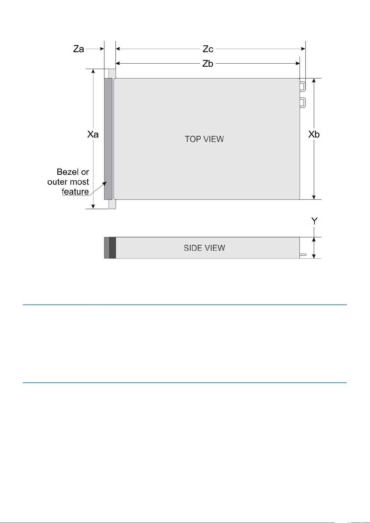
Figure 1. System dimensions of PowerEdge R7425 system
Table 1. Dimensions
System Xa Xb Y Za (with
PowerEdge R7425 482.0 mm
(18.98
inches)
434.0 mm
(17.09
inches)
86.8 mm
(3.42 inches)
bezel)
35.84 mm
(1.41 inches)
Chassis weight
Table 2. Chassis weight
System Maximum weight (with all drives/SSDs)
2.5 inch 28.4 kg (62.6 lb)
3.5 inch 33.4 kg (73.6 lb)
Processor specifications
The PowerEdge R7425 system supports up to two AMD EPYC™ processors.
Supported operating systems
The PowerEdge R7425 supports the following operating systems:
Za (without
bezel)
22.0 mm
(0.87 inches)
Zb Zc
677.3 mm
(26.66
inches)
715.63 mm
(28.17
inches)
6
Technical specifications
Page 7

• Microsoft Windows Server® with Hyper-V
• Red Hat® Enterprise Linux
• SUSE® Linux Enterprise Server3
Virtualization options:
• VMware® ESXi 6.7
NOTE: For more information about the specific versions and additions, go to https://www.dell.com/support/home/
Drivers/SupportedOS/poweredge-r7425.
PSU specifications
The PowerEdge R7425 system supports up to two AC or DC power supply units (PSUs).
Table 3. PSU specifications
PSU Class Heat
495 W AC Platinum 1908 BTU/hr
750 W AC Platinum 2891 BTU/hr 50/60 Hz 100–240 V
750 W AC Titanium 2843 BTU/hr 50/60 Hz 200–240 V
750 W Mixed
Mode HVDC
AC (for
China only)
750 W Mixed
Mode HVDC
DC(for China
only)
750 W Mixed
Mode AC
750 W Mixed
Mode DC
(for China
only)
1100 W AC Platinum 4100 BTU/hr 50/60 Hz 100–240 V
1100 W DC N/A 4416 BTU/hr N/A –(48–60) V
1100 W
Mixed Mode
HVDC (for
China and
Japan only)
1600 W AC Platinum 6000 BTU/hr 50/60 Hz 100–240 V
Platinum 2891 BTU/hr 50/60 Hz 100–240 V
Platinum 2891 BTU/hr N/A 240 V DC,
Platinum 2891 BTU/hr 50/60 Hz 100–240 V AC750 W 750 W N/A 10 A-5 A
Platinum 2891 BTU/hr N/A 240 V DC 750 W N/A 750 W 5 A
Platinum 4100 BTU/hr 50/60 Hz 100–240 V
N/A 4100 BTU/hr N/A 200–380 V
dissipation
(maximum)
Frequency Voltage High line
100–240 V
50/60 Hz
AC,
autoranging
AC,
autoranging
AC,
autoranging
AC,
autoranging
autoranging
AC,
autoranging
DC,
autoranging
AC,
autoranging
DC,
autoranging
AC,
autoranging
200v240 V
495 W 495 W N/A 6.5 A–3 A
750 W 750 W N/A 10 A–5 A
750 W N/A N/A 5 A
750 W 750 W N/A 10 A–5 A
N/A N/A 750 W 4.5 A
1100 W 1050 W N/A 12 A–6.5 A
N/A N/A 1100 W 32 A
1100 W 1050 W N/A 12 A–6.5 A
N/A N/A 1100 W 6.4 A–3.2 A
1600 W 800 W N/A
Low line
100– 140 V
DC Current
10 A
Technical specifications 7
Page 8

PSU Class Heat
dissipation
(maximum)
2000 W AC Platinum 7500 BTU/hr 50/60 Hz 100–240 V
2400 W AC Platinum 9000 BTU/hr 50/60 Hz 100–240 V
NOTE: Heat dissipation is calculated using the PSU wattage rating.
NOTE: This system is also designed to connect to the IT power systems with a phase to phase voltage not exceeding
240 V.
NOTE: PSUs rated for 1100 W AC or 1100 W Mixed Mode HVDC and higher require high-line voltage (200–240 V AC) to
supply their rated capacity.
Frequency Voltage High line
200v240 V
2000 W 1000 W N/A
AC,
autoranging
2400 W 1400 W N/A
AC,
autoranging
Low line
100– 140 V
DC Current
11.5 A
16 A
System battery specifications
The PowerEdge R7425 system supports CR 2032 3.0-V lithium coin cell system battery.
Expansion card riser specifications
The PowerEdge R7425 system supports up to eight PCI express (PCIe) generation 3 expansion cards that can be installed on the system
board using expansion card risers. The following table provides detailed information about the expansion card riser specifications:
Table 4. Expansion card riser specifications
PCIe slot Riser Processor
connection
1 1A Processor 1 Full height Full length x16
1D Processor 1 Full height Full length x16
1E Processor 1 Full height Full length x16
2 1D Processor 1 Full height Full length x8
1E Processor 1 Full height Full length x16
3 1A Processor 1 Full height Full length x16
1D Processor 1 Full height Full length x8
4 2D Processor 1 Full height Full length x16
2A Processor 2 Full height Full length x16
2E Processor 2 Full height Full length x16
5 2D Processor 2 Full height Full length x16
6 2D Processor 2 Low profile Half length x8
2A Processor 2 Low profile Half length x8
2C Processor 2 Low profile Half length x16
2E Processor 2 Low profile Half length x8
7 3A Processor 2 Full height Full length x8
3B Processor 2 Full height Full length x16
8 3A Processor 2 Full height Full length x16
3B Processor 2 Full height Full length x16
Height Length Slot width
8 Technical specifications
Page 9

Memory specifications
The PowerEdge R7425 system supports up to thirty two 288-pins RDIMMs, and LRDIMMs with speeds of 2666 MT/s, 2400 MT/s, 2133
MT/s, and 1866 MT/s with support for memory optimized operation.
Table 5. Memory specifications
DIMM
type
LRDIMM Quad rank 64GB 64GB 1TB 128GB 2TB
RDIMM Single rank 8GB 8GB 128GB 16GB 256GB
RDIMM Dual rank 16GB 16GB 256GB 32GB 512GB
RDIMM Dual rank 32GB 32GB 512GB 64GB 1024GB
NOTE: For optimal performance, it is recommended to populate one DIMM per channel with DDR4, 2666 MT/s memory
modules on the first slot of each memory channel. The first slot of each channel can be identified as the DIMM slots
with white latches. For example, 64 GB system memory capacity can be divided into 8 x 8 GB DIMM slots.
DIMM rank
DIMM
capacity
Minimum RAM Maximum RAM Minimum RAM Maximum RAM
Single processor Dual processors
Storage controller specifications
The PowerEdge R7425 system supports:
• Internal storage controller cards: PowerEdge RAID Controller (PERC) H330+, PERC H730+, PERC H740P, HBA330, S140, and Boot
Optimized Server Storage (BOSS-S1).
• External storage controller cards: PERC H840 and 12Gbps SAS HBA.
Drive specifications
Drives
The PowerEdge R7425 system supports SAS, SATA, Nearline SAS hard drives/SSDs, or NVMe drives.
Table 6. Supported drive options for the PowerEdge R7425 system
Configuration Description
8 drives system
12 drives system
18 drives system
24 drives system
24 drives system
24 drives system
32 drives system
• Up to eight 3.5 inch or 2.5 inch (SAS, SATA or Nearline SAS) front accessible drives in
slots 0 through 7
• Up to 12 3.5 inch (SAS, SATA or Nearline SAS) front accessible drives in slots 0 to 11
• Up to 12 3.5 inch (SAS, SATA or Nearline SAS) front accessible drives in slots 0 to 11
• up to four 3.5 inch (SAS, SATA or Nearline SAS) mid drives in slots 14 to 17
• up to two 3.5 inch (SAS, SATA or Nearline SAS) rear accessible drives in slots 12 to 13
• Up to 24 2.5 inch (SAS, SATA or Nearline SAS) front accessible drives in slots 0 to 23
• Up to 16 2.5 inch (SAS, SATA or Nearline SAS) front accessible drives in slots 0 to 15
• Up to 12 2.5 inch NVMe drives in 8 universal slots 16 ro 23
• Up to 24 2.5 inch NVMe drives in bay 1 (slots 0 to 11) and bay 2 (slots 0 to 11)
• Up to 8 2.5 inch (SAS, SATA or Nearline SAS) in 8 universal slots (bay 1 slot 0 to 7)
and 16 2.5 inch NVME drives in bay 1 (slots 8 to 11) and bay 2 (slot 0 to 11)
• Up to 24 2.5 inch (SAS, SATA or Nearline SAS) front accessible drives in slots 0 to 23
• up to four 3.5 inch (SAS, SATA or Nearline SAS) mid drives in slots 28 to 31
Technical specifications 9
Page 10

Configuration Description
• up to four 2.5 inch (SAS, SATA or Nearline SAS) rear accessible drives in slots 24 to
27
NOTE: Universal slots are slots that support SAS, SATA hard drives/SSDs, or NVMe drives in the same slot.
NOTE: Hot swap for the NVMe drives is supported for your system. For more information on correct usage and technical
specifications, see the
Dell.com/support/manuals > All Products > Server, Storage, & Networking > Dell Adapters page.
Dell PowerEdge Express Flash NVMe PCIe SSD 2.5 inch Small Form Factor User's Guide
Optical drive
The PowerEdge R7425 system supports one optional slim SATA DVD-ROM drive or DVD +/-RW drive.
Ports and connectors specifications
USB ports
The PowerEdge R7425 system supports:
• Two USB 2.0-compliant ports on the front of the system
• One internal USB 3.0-compliant port
• One optional USB 3.0-compliant port on the front of the system
• One micro USB 2.0-compliant port in the front of the system for iDRAC Direct
NOTE:
management port.
• Two USB 3.0-compliant ports on the back of the system
The micro USB 2.0 compliant port on the front of the system can only be used as an iDRAC Direct or a
at
NIC ports
The PowerEdge R7425 system supports up to four Network Interface Controller (NIC) ports that are integrated on the network daughter
card (NDC), and are available in the following configurations:
• Four RJ-45 ports that support 10, 100 and 1000 Mbps
• Four RJ-45 ports that support 100 M, 1 G and 10 Gbps
• Four RJ-45 ports, where two ports support maximum of 10 G and the other two ports maximum of 1 G
• Two RJ-45 ports that support up to 1 Gbps and 2 SFP+ ports that support up to 10 Gbps
• Four SFP+ ports that support up to 10 Gbps
• Two SFP28 ports that support up to 25 Gbps
NOTE:
NOTE: For information about Linux network settings, see the
Based Servers
You can install up to eight PCIe add-on NIC cards.
Linux® Network Tuning Guide for AMD EPYC™ Processor
AMD tuning guide.
VGA ports
The Video Graphic Array (VGA) port enables you to connect the system to a VGA display. The PowerEdge R7425 system supports two
15-pin VGA ports on the front and back panels.
Serial connector
The PowerEdge R7425 system supports one serial connector on the back panel, which is a 9-pin connector, Data Terminal Equipment
(DTE), 16550-compliant.
10
Technical specifications
Page 11

IDSDM or vFlash module
The PowerEdge R7425 system supports optional Internal Dual SD module (IDSDM) or vFlash module. In 14th generation of PowerEdge
servers, IDSDM or vFlash module are combined into a single card module, and are available in these configurations:
• vFlash or
• vFlash and IDSDM
The IDSDM or vFlash module sits in the back of the system, in a Dell-proprietary slot. IDSDM or vFlash module supports three micro SD
cards (two cards for IDSDM and one card for vFlash). Micro SD cards capacity for IDSDM are 16, 32, 64 GB while for vFlash the microSD
card capacity is 16 GB.
NOTE: There are two dip switches on the IDSDM or vFlash module for write-protection.
NOTE: One IDSDM card slot is dedicated for redundancy.
NOTE: It is recommended to use Dell branded MicroSD cards associated with the IDSDM or vFlash configured systems.
Video specifications
The PowerEdge R7425 system supports integrated Matrox G200eW3 graphics controller with 16 MB of video frame buffer.
Table 7. Supported video resolution options
Resolution Refresh rate (Hz) Color depth (bits)
1024 x 768 60 8, 16, 32
1280 x 800 60 8, 16, 32
1280 x 1024 60 8, 16, 32
1360 x 768 60 8, 16, 32
1440 x 900 60 8, 16, 32
1600 x 900 60 8, 16, 32
1600 x 1200 60 8, 16, 32
1680 x 1050 60 8, 16, 32
1920 x 1080 60 8, 16, 32
1920 x 1200 60 8, 16, 32
NOTE: 1920 x 1080 and 1920 x 1200 resolutions are only supported in reduced blanking mode.
Environmental specifications
NOTE:
Datasheet located with the Manuals & Documents on support.dell.com.
Table 8. Temperature specifications
Temperature Specifications
Storage –40°C to 65°C (–40°F to 149°F)
Continuous operation (for altitude less than 950 m or 3117
ft)
Maximum temperature gradient (operating and storage) 20°C/h (68°F/h)
For additional information about environmental certifications, please refer to the Product Environmental
10°C to 35°C (50°F to 95°F) with no direct sunlight on the equipment.
Technical specifications 11
Page 12

Table 9. Relative humidity specifications
Relative humidity Specifications
Storage 5% to 95% RH with 33°C (91°F) maximum dew point. Atmosphere must be
non-condensing at all times.
Operating 10% to 80% relative humidity with 29°C (84.2°F) maximum dew point.
Table 10. Maximum vibration specifications
Maximum vibration Specifications
Operating 0.26 G
Storage 1.88 G
Table 11. Maximum shock specifications
Maximum shock Specifications
Operating Six consecutively executed shock pulses in the positive and negative x, y,
and z axes of 6 G for up to 11 ms.
Storage Six consecutively executed shock pulses in the positive and negative x, y,
and z axes (one pulse on each side of the system) of 71 G for up to 2 ms.
Table 12. Maximum altitude specifications
Maximum altitude Specifications
Operating
3048 m (10,000 ft)
at 5 Hz to 350 Hz (all three axes).
rms
at 10 Hz to 500 Hz for 15 min (all six sides tested).
rms
Storage 12,000 m (39,370 ft)
Table 13. Operating temperature de-rating specifications
Operating temperature de-rating Specifications
Up to 35°C (95°F) Maximum temperature is reduced by 1°C/300 m (1°F/547 ft) above 950 m
(3,117 ft).
35°C to 40°C (95°F to 104°F) Maximum temperature is reduced by 1°C/175 m (1°F/319 ft) above 950 m
(3,117 ft).
40°C to 45°C (104°F to 113°F) Maximum temperature is reduced by 1°C/125 m (1°F/228 ft) above 950 m
(3,117 ft).
Standard operating temperature
Table 14. Standard operating temperature specifications
Standard operating temperature Specifications
Continuous operation (for altitude less than 950 m or 3117
ft)
10°C to 35°C (50°F to 95°F) with no direct sunlight on the equipment.
Expanded operating temperature
Table 15. Expanded operating temperature specifications
Expanded operating temperature Specifications
Continuous operation 5°C to 40°C at 5% to 85% RH with 29°C dew point.
NOTE: Outside the standard operating temperature (10°C to
35°C), the system can operate continuously in temperatures as
low as 5°C and as high as 40°C.
12 Technical specifications
Page 13

Expanded operating temperature Specifications
For temperatures between 35°C to 40°C, de-rate maximum allowable
temperature by 1°C per 175 m above 950 m (1°F per 319 ft).
≤ 1% of annual operating hours –5°C to 45°C at 5% to 90% RH with 29°C dew point.
NOTE: Outside the standard operating temperature (10°C to
35°C), the system can operate down to –5°C or up to 45°C for a
maximum of 1% of its annual operating hours.
For temperatures between 40°C and 45°C, de-rate maximum allowable
temperature by 1°C per 125 m above 950 m (1°F per 228 ft).
NOTE: When operating in the expanded temperature range, system performance may be impacted.
NOTE: When operating in the expanded temperature range, ambient temperature warnings may be reported in the
System Event Log.
Expanded operating temperature restrictions
• Do not perform a cold startup below 5°C.
• The operating temperature specified is for a maximum altitude of 3050 m (10,000 ft).
• 180 W/200 W CPUs are not supported.
• Redundant power supply unit is required.
• Non-Dell qualified peripheral cards and/or peripheral cards greater than 25 W are not supported.
• PCIe SSD is not supported.
• Mid drive tray is not supported.
• Rear storage devices or drives are not supported.
• GPU is not supported
Thermal restrictions
Following table lists the configuration required for efficient cooling.
Table 16. Thermal restrictions matrix table
Config
number
1 3.5" x 8 PCIe x 8 1 2U HSK,
2a 2.5" x 24 PCIe x 8 2 2U HSK,
Storage
module
Middle/
rear
configura
tion
GPGPU x 32 1U HPR
GPGPU x 32 1U HPR
CPU
count
2 2U HSK,
Thermal solution
(heat sink)
180W/
200W
CPU
2JYG2
2JYG2
HSK,
4CFPC
2JYG2
HSK,
4CFPC
155W/
170W and
120W
CPU
1U STD
HSK,
GDYH1
1U STD
HSK,
GDYH1
1U STD
HSK,
GDYH1
1U STD
HSK,
GDYH1
1U STD
HSK,
GDYH1
Shroud and blank
Fan Shroud DIMM
STD x4,
4VKDD
STD x6,
4V1WX
HPR X6,
15G45
STD x6,
4V1WX
HPR X6,
15G45
Standard No Yes Yes
Standard No No No
GPGPU No No No
Standard No No No
GPGPU No No No
blank
CPU
blank
Fan blank
Technical specifications 13
Page 14

Config
number
2b 2.5"x16 +
Storage
module
NVMe x 8
Middle/
rear
configura
tion
PCIe x 7 2 2U HSK,
CPU
count
Thermal solution
(heat sink)
180W/
200W
CPU
2JYG2
155W/
170W and
120W
CPU
1U STD
HSK,
GDYH1
Shroud and blank
Fan Shroud DIMM
STD x6,
4V1WX
Standard No No No
blank
CPU
blank
Fan blank
GPGPU x 32 1U HPR
HSK,
4CFPC
2d 2.5" x 32 Middle
2.5" x 4 +
Rear 2.5"
x 4
3a 3.5" x 12 PCIe x 8 2 2U HSK,
3b 3.5" x 18 Middle
3.5" x 4 +
Rear 3.5"
x 2
4 NVMe x 24PCIe x 7 2 2U HSK,
4 GPGPU x 32 1U HPR
2 1U HPR
HSK,
4CFPC
2JYG2
2 1U HPR
HSK,
4CFPC
2JYG2
HSK,
4CFPC
1U STD
HSK,
GDYH1
1U STD
HSK,
GDYH1
1U STD
HSK,
GDYH1
1U STD
HSK,
GDYH1
1U STD
HSK,
GDYH1
1U STD
HSK,
GDYH1
HPR X6,
15G45
HPR X6,
15G45
STD x6,
4V1WX
HPR X6,
15G45
STD x6,
4V1WX
HPR X6,
15G45
Other thermal restrictions
The list below are other thermal restrictions:
1. Mellanox CX4 and CX5 only support up to 35°C ambient with limited slots 1, 7, and 8
GPGPU No No No
No Yes, x30
5M8WD*
Standard No No No
No Yes, x30
5M8WD*
Standard No No No
GPGPU No No No
No No
No No
Ambient temperature limitations
The following table lists configurations that require ambient temperature less than 35°C.
NOTE:
which may impact system performance.
Table 17. Configuration based ambient temperature restrictions
Storage
configuration
12 x 3.5 inch
12 x 3.5 inch
24 x 2.5 inch
24 x 2.5 inch
The ambient temperature limit must be adhered to ensure proper cooling and to avoid excess CPU throttling,
Chassis or
hardware
configuration
Mid (SAS) and
rear drive
Mid (SAS) and
rear drive
Mid (SAS) and
rear drive
All PCIe cards 200 W/180 W 2U Standard 35°C
CPU Thermal
Design Power
(TDP)
200 W/180 W 1U high performance High performance 30°C
120-170 W 1U standard High performance 35°C
All
CPU heat sink Fan type
1U high performance for
180/200W
1U standard for 120-170W
Ambient
restriction
High performance 35°C
14 Technical specifications
Page 15

Storage
configuration
12 x 3.5 inch
Chassis or
hardware
configuration
All PCIe cards 200 W/180 W 2U Standard 35°C
CPU Thermal
Design Power
(TDP)
CPU heat sink Fan type
Ambient
restriction
8 x 3.5 inch
24 NVMe
16 x 2.5 inch SAS + 8
NVMe + 24 NVMe
All PCIe cards 200 W/180 W 2U Standard 35°C
All PCIe cards 200 W/180 W 2U Standard 35°C
All PCIe cards 120-170 W 1U standard Standard 35°C
Particulate and gaseous contamination specifications
The following table defines the limitations that help avoid any equipment damage or failure from particulate and gaseous contamination. If
the levels of particulate or gaseous pollution exceed the specified limitations and result in equipment damage or failure, you may need to
rectify the environmental conditions. Remediation of environmental conditions is the responsibility of the customer.
Table 18. Particulate contamination specifications
Particulate contamination Specifications
Air filtration Data center air filtration as defined by ISO Class 8 per ISO 14644-1 with a
95% upper confidence limit.
NOTE: The ISO Class 8 condition applies to data center
environments only. This air filtration requirement does not apply
to IT equipment designed to be used outside a data center, in
environments such as an office or factory floor.
NOTE: Air entering the data center must have MERV11 or
MERV13 filtration.
Conductive dust Air must be free of conductive dust, zinc whiskers, or other conductive
particles.
NOTE: This condition applies to data center and non-data center
environments.
Corrosive dust
Table 19. Gaseous contamination specifications
Gaseous contamination Specifications
Copper coupon corrosion rate <300 Å/month per Class G1 as defined by ANSI/ISA71.04-2013.
Silver coupon corrosion rate <200 Å/month as defined by ANSI/ISA71.04-2013.
NOTE: Maximum corrosive contaminant levels measured at ≤50% relative humidity.
• Air must be free of corrosive dust.
• Residual dust present in the air must have a deliquescent point less than
60% relative humidity.
NOTE: This condition applies to data center and non-data center
environments.
Technical specifications 15
Page 16

Documentation resources
This section provides information about the documentation resources for your system.
To view the document that is listed in the documentation resources table:
• From the Dell EMC support site:
1. Click the documentation link that is provided in the Location column in the table.
2. Click the required product or product version.
NOTE:
3. On the Product Support page, click Manuals & documents.
• Using search engines:
• Type the name and version of the document in the search box.
Table 20. Additional documentation resources for your system
Task Document Location
Setting up your system
To locate the product name and model, see the front of your system.
For more information about installing and securing
the system into a rack, see the Rail Installation
Guide included with your rack solution.
For information about installing the system into a
rack, see the Rack documentation included with
your rack solution or the Getting Started Guide
document that is shipped with your system.
For information about installing the system into a
rack, see the Rack documentation included with
the
Getting Started With Your System document
that is shipped with your system.
For information about installing the system into
the enclosure, see the Getting Started Guide
document that is shipped with your system.
For information about setting up your system, see
the Getting Started Guide document that is
shipped with your system.
www.dell.com/dssmanuals
www.dell.com/poweredgemanuals
3
Configuring your system For information about the iDRAC features,
configuring and logging in to iDRAC, and managing
your system remotely, see the Integrated Dell
Remote Access Controller User's Guide.
For information about understanding Remote
Access Controller Admin (RACADM)
subcommands and supported RACADM
interfaces, see the RACADM CLI Guide for iDRAC.
For information about Redfish and its protocol,
supported schema, and Redfish Eventing are
implemented in iDRAC, see the Redfish API Guide.
For information about iDRAC property database
group and object descriptions, see the Attribute
Registry Guide.
For information about Intel QuickAssist
Technology, see the Integrated Dell Remote
Access Controller User's Guide.
16 Documentation resources
www.dell.com/poweredgemanuals
Page 17

Task Document Location
For information about earlier versions of the
iDRAC documents, see the iDRAC documentation.
To identify the version of iDRAC available on your
system, on the iDRAC web interface, click
About.
? >
www.dell.com/idracmanuals
For information about installing the operating
system, see the operating system documentation.
For information about updating drivers and
firmware, see the Methods to download firmware
and drivers section in this document.
Managing your system For information about systems management
software offered by Dell, see the Dell
OpenManage Systems Management Overview
Guide.
For information about setting up, using, and
troubleshooting OpenManage, see the Dell
OpenManage Server Administrator User’s Guide.
For information about installing, using, and
troubleshooting Dell OpenManage Essentials, see
the Dell OpenManage Essentials User’s Guide.
For information about installing, using, and
troubleshooting Dell OpenManage Enterprise, see
the Dell OpenManage Enterprise User’s Guide.
For information about installing and using Dell
SupportAssist, see the Dell EMC SupportAssist
Enterprise User’s Guide.
For information about partner programs enterprise
systems management, see the OpenManage
Connections Enterprise Systems Management
documents.
www.dell.com/operatingsystemmanuals
www.dell.com/support/drivers
www.dell.com/poweredgemanuals
www.dell.com/openmanagemanuals >
OpenManage Server Administrator
www.dell.com/openmanagemanuals >
OpenManage Essentials
www.dell.com/openmanagemanuals >
OpenManage Enterprise
www.dell.com/serviceabilitytools
www.dell.com/openmanagemanuals
Working with the Dell
PowerEdge RAID controllers
Understanding event and error
messages
Fan Control Board firmware
update and Set Chassis Type
procedure
For information about viewing inventory,
performing configuration, and monitoring tasks,
remotely turning on or off servers, and enabling
alerts for events on servers and components using
the Dell Chassis Management Controller (CMC),
see the CMC User’s Guide.
For information about understanding the features
of the Dell PowerEdge RAID controllers (PERC),
Software RAID controllers, or BOSS card and
deploying the cards, see the Storage controller
documentation.
For information about the event and error
messages that are generated by the system
firmware and agents that monitor system
components, see the Error Code Lookup.
For information about updating the Fan Control
Board firmware and setting the chassis type to
accommodate either PowerEdge C6320 or
PowerEdge C6320p sleds in the PowerEdge
C6300 enclosure, see the Fan Control Board
firmware update and Set Chassis Type procedure
section in this document.
www.dell.com/openmanagemanuals > Chassis
Management Controllers
www.dell.com/storagecontrollermanuals
www.dell.com/qrl
www.dell.com/poweredgemanuals
Documentation resources 17
Page 18

Task Document Location
Troubleshooting your system For information about identifying and
troubleshooting the PowerEdge server issues, see
the Server Troubleshooting Guide.
www.dell.com/poweredgemanuals
18 Documentation resources
Page 19

4
Getting help
Topics:
• Contacting Dell
• Documentation feedback
• Accessing system information by using QRL
• Receiving automated support with SupportAssist
• Recycling or End-of-Life service information
Contacting Dell
Dell provides several online and telephone based support and service options. If you do not have an active internet connection, you can
find contact information about your purchase invoice, packing slip, bill, or Dell product catalog. Availability varies by country and product,
and some services may not be available in your area. To contact Dell for sales, technical assistance, or customer service issues:
1. Go to www.dell.com/support/home
2. Select your country from the drop-down menu on the lower right corner of the page.
3. For customized support:
a) Enter your system Service Tag in the Enter your Service Tag field.
b) Click Submit.
The support page that lists the various support categories is displayed.
4. For general support:
a) Select your product category.
b) Select your product segment.
c) Select your product.
The support page that lists the various support categories is displayed.
5. For contact details of Dell Global Technical Support:
a) Click Global Technical Support
b) The Contact Technical Support page is displayed with details to call, chat, or e-mail the Dell Global Technical Support team.
Documentation feedback
You can rate the documentation or write your feedback on any of our Dell EMC documentation pages and click Send Feedback to send
your feedback.
Accessing system information by using QRL
You can use the Quick Resource Locator (QRL) to get immediate access to the information about your system. The QRL is located on the
top of the system cover and provides access to generic information about your system. If you want to access information specific to the
system service tag, such as configuration and warranty, you can access QR code located on the system Information tag.
Ensure that your smart phone or tablet has the QR code scanner installed.
The QRL includes the following information about your system:
• How-to videos
• Reference materials, including the Owner’s Manual, LCD diagnostics, and mechanical overview
• A direct link to Dell to contact technical assistance and sales teams
1. Go to www.dell.com/qrl and navigate to your specific product or
2. Use your smart phone or tablet to scan the model-specific Quick Resource (QR) code on your PowerEdge system or in the Quick
Resource Locator section.
Getting help 19
Page 20

Quick Resource Locator for PowerEdge R7425 system
Figure 2. Quick Resource Locator for PowerEdge R7425 system
Receiving automated support with SupportAssist
Dell EMC SupportAssist is an optional Dell EMC Services offering that automates technical support for your Dell EMC server, storage, and
networking devices. By installing and setting up a SupportAssist application in your IT environment, you can receive the following benefits:
• Automated issue detection — SupportAssist monitors your Dell EMC devices and automatically detects hardware issues, both
proactively and predictively.
• Automated case creation — When an issue is detected, SupportAssist automatically opens a support case with Dell EMC Technical
Support.
• Automated diagnostic collection — SupportAssist automatically collects system state information from your devices and uploads it
securely to Dell EMC. This information is used by Dell EMC Technical Support to troubleshoot the issue.
• Proactive contact — A Dell EMC Technical Support agent contacts you about the support case and helps you resolve the issue.
The available benefits vary depending on the Dell EMC Service entitlement purchased for your device. For more information about
SupportAssist, go to www.dell.com/supportassist.
Recycling or End-of-Life service information
Take back and recycling services are offered for this product in certain countries. If you want to dispose of system components, visit
www.dell.com/recyclingworldwide and select the relevant country.
20
Getting help
 Loading...