

Page 1

Dell™ PowerEdge™ R715
Hardware Owner’s
Manual
Regulatory Model: E05S
Regulatory Type: E05S001
Page 2
Notes, Cautions, and Warnings
NOTE: A NOTE indicates important information that helps you make better use of
your computer.
CAUTION: A CAUTION indicates potential damage to hardware or loss of data if
instructions are not followed.
WARNING: A WARNING indicates a potential for property damage, personal
injury, or death.
____________________
Information in this document is subject to change without notice.
© 2010 Dell Inc. All rights reserved.
Reproduction of these materials in any manner whatsoever without the written permission of Dell Inc.
is strictly forbidden.
Trademarks used in this text: Dell, the DELL logo, and PowerEdge are trademarks of Dell Inc.
Microsoft, Windows, and Windows Server are either trademarks or registered trademarks of Microsoft
Corporation in the United States and/or other countries.
Other trademarks and trade names may be used in this document to refer to either the entities claiming
the marks and names or their products. Dell Inc. disclaims any proprietary interest in trademarks and
trade names other than its own.
Regulatory Model: E05S
Regulatory Type: E05S001
May 2010 Rev. A00
Page 3

Contents
1 About Your System. . . . . . . . . . . . . . . . . . 11
Accessing System Features During Startup. . . . . . . 11
Front-Panel Features and Indicators
. . . . . . . . . . 12
LCD Panel Features . . . . . . . . . . . . . . . . . . . 14
Home Screen
. . . . . . . . . . . . . . . . . . . . 15
Setup Menu. . . . . . . . . . . . . . . . . . . . . 16
View Menu
Hard-Drive Indicator Patterns
. . . . . . . . . . . . . . . . . . . . . 17
. . . . . . . . . . . . . . 17
Back-Panel Features and Indicators . . . . . . . . . . 18
Guidelines for Connecting External Devices
NIC Indicator Codes
Power Indicator Codes
LCD Status Messages
Viewing Status Messages
. . . . . . . . . . . . . . . . . . . 21
. . . . . . . . . . . . . . . . . 21
. . . . . . . . . . . . . . . . . . 23
. . . . . . . . . . . . . 23
. . . . . . 20
Removing LCD Status Messages . . . . . . . . . . 23
System Messages . . . . . . . . . . . . . . . . . . . . 39
Warning Messages
. . . . . . . . . . . . . . . . . . . 52
Diagnostics Messages
Alert Messages
. . . . . . . . . . . . . . . . . . . . . 52
. . . . . . . . . . . . . . . . . 52
Contents 3
Page 4

Other Information You May Need . . . . . . . . . . . . 53
2 Using the System Setup Program and
UEFI Boot Manager . . . . . . . . . . . . . . . . . 55
Choosing the System Boot Mode . . . . . . . . . . . . 55
Entering the System Setup Program
Responding to Error Messages
. . . . . . . . . . . 56
. . . . . . . . . . . 56
Using the System Setup Program
Navigation Keys . . . . . . . . . . . . . . . . . . . 56
System Setup Options . . . . . . . . . . . . . . . . . . 57
Main Screen
. . . . . . . . . . . . . . . . . . . . 57
Memory Settings Screen . . . . . . . . . . . . . . 59
Processor Settings Screen
SATA Settings Screen
. . . . . . . . . . . . . 60
. . . . . . . . . . . . . . . . 61
Boot Settings Screen . . . . . . . . . . . . . . . . 61
Integrated Devices Screen
. . . . . . . . . . . . . 62
PCI IRQ Assignments Screen . . . . . . . . . . . . 63
Serial Communication Screen
Power Management Screen
. . . . . . . . . . . 63
. . . . . . . . . . . . 64
System Security Screen . . . . . . . . . . . . . . 65
Exit Screen
Entering the UEFI Boot Manager
. . . . . . . . . . . . . . . . . . . . . 66
. . . . . . . . . . . . . 66
Using the UEFI Boot Manager
Navigation Keys
UEFI Boot Manager Screen
. . . . . . . . . . . . . . . . . . . 67
. . . . . . . . . . . . . 67
UEFI Boot Settings Screen . . . . . . . . . . . . . 68
System Utilities Screen
. . . . . . . . . . . . . . . 68
4 Contents
System and Setup Password Features
Using the System Password
Using the Setup Password
. . . . . . . . . . . . 69
. . . . . . . . . . . . . 71
. . . . . . . . . . 69
Page 5

Embedded System Management . . . . . . . . . . . . 72
iDRAC6 Configuration Utility
Entering the iDRAC6 Configuration Utility
. . . . . . . . . . . . . . 73
. . . . . 73
3 Installing System Components . . . . . . . . 75
Recommended Tools. . . . . . . . . . . . . . . . . . . 75
Inside the System . . . . . . . . . . . . . . . . . . . . 75
Front Bezel (Optional)
Removing the Front Bezel
Installing the Front Bezel
Opening and Closing the System
Opening the System
Closing the System
Hard Drives
. . . . . . . . . . . . . . . . . . . . . . . . 80
Removing a Hard-Drive Blank
Installing a Hard-Drive Blank. . . . . . . . . . . . 81
Removing a Hard-Drive Carrier
Installing a Hard-Drive Carrier
Removing a Hard Drive From a
Hard-Drive Carrier
Installing a Hard Drive Into a
Hard-Drive Carrier . . . . . . . . . . . . . . . . . 84
. . . . . . . . . . . . . . . . . . 77
. . . . . . . . . . . . . 77
. . . . . . . . . . . . . . 77
. . . . . . . . . . . . 78
. . . . . . . . . . . . . . . . 78
. . . . . . . . . . . . . . . . . 79
. . . . . . . . . . . 80
. . . . . . . . . . . 82
. . . . . . . . . . . 83
. . . . . . . . . . . . . . . . . 84
Optical Drive . . . . . . . . . . . . . . . . . . . . . . . 85
Removing an Optical Drive
Installing an Optical Drive
Power Supplies
. . . . . . . . . . . . . . . . . . . . . 87
Removing a Power Supply
Installing a Power Supply
. . . . . . . . . . . . . 85
. . . . . . . . . . . . . 86
. . . . . . . . . . . . . 88
. . . . . . . . . . . . . 89
Contents 5
Page 6

Removing the Power Supply Blank . . . . . . . . . 89
Installing the Power Supply Blank . . . . . . . . . 89
Cooling Shroud . . . . . . . . . . . . . . . . . . . . . . 90
Removing the Cooling Shroud
. . . . . . . . . . . 90
Installing the Cooling Shroud . . . . . . . . . . . . 91
System Memory . . . . . . . . . . . . . . . . . . . . . 92
General Memory Module Installation
Guidelines
Memory Sparing Support
Installing Memory Modules
. . . . . . . . . . . . . . . . . . . . . . 92
. . . . . . . . . . . . . . 93
. . . . . . . . . . . . . 95
Removing Memory Modules . . . . . . . . . . . . 97
Cooling Fans . . . . . . . . . . . . . . . . . . . . . . . 98
Removing a Cooling Fan
. . . . . . . . . . . . . . 98
Installing a Cooling Fan . . . . . . . . . . . . . . 100
Removing the Cooling Fan Assembly
Installing the Cooling Fan Assembly
. . . . . . . 100
. . . . . . . 102
6 Contents
Internal USB Memory Key (Optional)
Internal NIC Hardware Key
. . . . . . . . . . . . . . 103
Expansion Cards and Expansion-Card Risers
Expansion Card Installation Guidelines
Installing an Expansion Card
Removing an Expansion Card
. . . . . . . . . 102
. . . . . 105
. . . . . . 105
. . . . . . . . . . . 106
. . . . . . . . . . . 108
Removing Expansion-Card Riser 1 . . . . . . . . 109
Installing Expansion-Card Riser 1
Removing Expansion-Card Riser 2
Installing Expansion-Card Riser 2
Integrated Storage Controller Card
. . . . . . . . . 111
. . . . . . . . 111
. . . . . . . . . 113
. . . . . . . . . . 113
Removing the Integrated Storage
Controller Card
. . . . . . . . . . . . . . . . . . 113
Page 7

Installing the Integrated Storage
Controller Card
. . . . . . . . . . . . . . . . . . . 115
RAID Battery (Optional) . . . . . . . . . . . . . . . . . 116
Removing a RAID Battery
. . . . . . . . . . . . . . 116
Installing the RAID Battery . . . . . . . . . . . . . 117
iDRAC6 Enterprise Card (Optional) . . . . . . . . . . . 118
Removing an iDRAC6 Enterprise Card
. . . . . . . 118
Installing an iDRAC6 Enterprise Card . . . . . . . 120
VFlash Media (Optional) . . . . . . . . . . . . . . . . . 121
Removing a VFlash Media Card
. . . . . . . . . . 121
Installing a VFlash Media Card . . . . . . . . . . . 121
Internal Dual SD Module (Optional). . . . . . . . . . . 121
Removing the Internal Dual SD Module
. . . . . . 121
Installing the Internal Dual SD Module. . . . . . . 123
Processors . . . . . . . . . . . . . . . . . . . . . . . . 123
Removing a Processor
. . . . . . . . . . . . . . . 123
Installing a Processor . . . . . . . . . . . . . . . 128
System Battery
Replacing the System Battery
SAS Backplane
Removing the SAS Backplane
. . . . . . . . . . . . . . . . . . . . . . 130
. . . . . . . . . . . 130
. . . . . . . . . . . . . . . . . . . . . 132
. . . . . . . . . . . 132
Installing the SAS Backplane . . . . . . . . . . . 134
Power Distribution Board . . . . . . . . . . . . . . . . 135
Removing the Power Distribution Board
Installing the Power Distribution Board
Control Panel Assembly
. . . . . . . . . . . . . . . . . 138
. . . . . . 135
. . . . . . 137
Removing the Control Panel Display
. . . . . . . . . . . . . . . . . . . . . . . 138
Module
Contents 7
Page 8

Installing the Control Panel Display
. . . . . . . . . . . . . . . . . . . . . . 139
Module
Removing the Control Panel Board
Installing the Control Panel Board
. . . . . . . . 141
. . . . . . . . 142
System Board Assembly
Removing the System Board Assembly
Installing the System Board Assembly
. . . . . . . . . . . . . . . . 143
. . . . . . 143
. . . . . . 146
4 Troubleshooting Your System . . . . . . . . 149
Safety First—For You and Your System . . . . . . . . 149
Troubleshooting System Startup Failure
Troubleshooting External Connections . . . . . . . . 149
Troubleshooting the Video Subsystem
Troubleshooting a USB Device
Troubleshooting a Serial I/O Device
Troubleshooting a NIC . . . . . . . . . . . . . . . . . 151
Troubleshooting a Wet System
. . . . . . . . . . . . . 152
Troubleshooting a Damaged System
Troubleshooting the System Battery. . . . . . . . . . 154
. . . . . . . . 149
. . . . . . . . . 150
. . . . . . . . . . . . 150
. . . . . . . . . . 151
. . . . . . . . . . 153
8 Contents
Troubleshooting Power Supplies
. . . . . . . . . . . 155
Troubleshooting System Cooling Problems
Troubleshooting a Fan
Troubleshooting System Memory
Troubleshooting an Internal USB Key
. . . . . . . . . . . . . . 156
. . . . . . . . . . . 157
. . . . . . . . . 159
. . . . . . 155
Page 9

Troubleshooting an SD Card . . . . . . . . . . . . . . . 160
Troubleshooting an Optical Drive
Troubleshooting a Hard Drive
. . . . . . . . . . . . 161
. . . . . . . . . . . . . . 162
Troubleshooting a Storage Controller . . . . . . . . . . 163
Troubleshooting Expansion Cards
Troubleshooting the Processors
. . . . . . . . . . . . 164
. . . . . . . . . . . . . 166
5 Running the System Diagnostics . . . . . . 169
Using Online Diagnostics . . . . . . . . . . . . . . . . 169
Embedded System Diagnostics Features
When to Use the Embedded System
Diagnostics
. . . . . . . . . . . . . . . . . . . . . . . 170
Running the Embedded System Diagnostics
System Diagnostics Testing Options
Using the Custom Test Options . . . . . . . . . . . . . 171
Selecting Devices for Testing
Selecting Diagnostics Options
Viewing Information and Results
. . . . . . . . 169
. . . . . . 170
. . . . . . . . . . 170
. . . . . . . . . . . 171
. . . . . . . . . . . 171
. . . . . . . . . . 172
6 Jumpers and Connectors . . . . . . . . . . . 173
System Board Jumper . . . . . . . . . . . . . . . . . . 173
System Board Connectors
SAS Backplane Board Connectors
. . . . . . . . . . . . . . . . 174
. . . . . . . . . . . 177
Contents 9
Page 10

Power Distribution Board Connectors. . . . . . . . . 178
Expansion-Card Riser-Board Components and
PCIe Buses
. . . . . . . . . . . . . . . . . . . . . . . 179
Disabling a Forgotten Password
. . . . . . . . . . . . 181
7 Getting Help . . . . . . . . . . . . . . . . . . . . . . 183
Contacting Dell. . . . . . . . . . . . . . . . . . . . . 183
Index . . . . . . . . . . . . . . . . . . . . . . . . . . . . . . 185
10 Contents
Page 11

1
About Your System
Accessing System Features During Startup
The following keystrokes provide access to system features during startup.
Keystroke Description
<F2> Enters the System Setup program. See "Using the System Setup
Program and UEFI Boot Manager" on page 55.
<F10> Enters System Services, which opens the Lifecycle Controller. The
Lifecycle Controller allows you to access utilities such as embedded
system diagnostics. For more information, see the Lifecycle Controller
documentation at
<F11> Enters the BIOS Boot Manager or the UEFI Boot Manager,
depending on the system's boot configuration. See "Using the System
Setup Program and UEFI Boot Manager" on page 55.
<F12> Starts PXE boot.
<Ctrl><E> Enters the iDRAC Configuration Utility, which allows access to the
System Event Log (SEL) and configuration of remote access to the
system. For more information, see the iDRAC user documentation at
support.dell.com/manuals.
<Ctrl><C> Enters the SAS Configuration Utility. For more information, see the
SAS adapter documentation at
<Ctrl><R> Enters the PERC configuration utility. For more information, see the
PERC card documentation at support.dell.com/manuals.
<Ctrl><S> Enters the utility to configure NIC settings for PXE boot. For more
information, see the documentation for your integrated NIC at
support.dell.com/manuals.
support.dell.com/manuals.
support.dell.com/manuals.
About Your System 11
Page 12

Front-Panel Features and Indicators
1 2
34
67
9
10
5
8
Figure 1-1. Front-Panel Features and Indicators
Item Indicator, Button, or
Connector
1Power-on indicator,
power button
12 About Your System
Icon Description
The power-on indicator lights when the
system power is on.
The power button controls the DC
power supply output to the system.
When the system bezel is installed, the
power button is not accessible.
NOTE: When powering on the system, the
video monitor can take from several
seconds to over two minutes to display an
image, depending on the amount of
memory installed in the system.
NOTE: On ACPI-compliant operating
systems, turning off the system using the
power button causes the system to
perform a graceful shutdown before
power to the system is turned off.
Page 13
Item Indicator, Button, or
Connector
2 NMI button Used to troubleshoot software and
3 USB connectors (2) Connect USB devices to the system. The
4 Video connector Connects a monitor to the system.
5 System identification
panel
6 LCD menu buttons Allows you to navigate the control panel
7 LCD panel Provides system ID, status information,
Icon Description
device driver errors when using certain
operating systems. This button can be
pressed using the end of a paper clip.
Use this button only if directed to do so
by qualified support personnel or by the
operating system's documentation.
ports are USB 2.0-compliant.
A slide-out panel for system information
including the Express Service Tag,
embedded NIC MAC address, and
iDRAC6 Enterprise card MAC address.
Space is provided for an additional label.
LCD menu.
and system error messages.
The LCD lights blue during normal
system operation. The LCD lights
amber when the system needs attention,
and the LCD panel displays an error
code followed by descriptive text.
NOTE: If the system is connected to AC
power and an error has been detected,
the LCD lights amber regardless of
whether the system has been powered on.
8 System identification
button
The identification buttons on the front
and back panels can be used to locate a
particular system within a rack. When
one of these buttons is pushed, the LCD
panel on the front and the system status
indicator on the back blinks until one of
the buttons is pushed again.
About Your System 13
Page 14
Item Indicator, Button, or
4
3
2
1
Connector
9Optical drive
(optional)
Icon Description
One optional slim-line SATA
DVD-ROM drive or DVD-RW drive.
NOTE: DVD devices are data only.
10 Hard drives Up to six 2.5", external hot-swappable
SAS, SATA, or SSD hard drives.
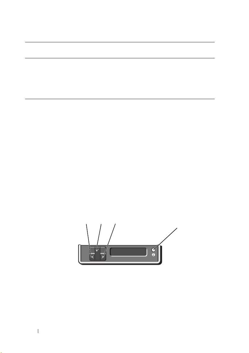
LCD Panel Features
The system's LCD panel provides system information and status and error
messages to signify when the system is operating correctly or when the system
needs attention. See "LCD Status Messages" on page 23 for information
about specific status codes.
The LCD backlight lights blue during normal operating conditions and lights
amber to indicate an error condition. When the system is in standby mode, the
LCD backlight is off and can be turned on by pressing the Left, Select, or Right
button on the LCD panel. The LCD backlight remains off if LCD messaging is
turned off through the iDRAC6 utility, the LCD panel, or other tools.
Figure 1-2. LCD Panel Features
14 About Your System
Page 15

Item Buttons Description
1 Left Moves the cursor back in one-step increments.
2 Select Selects the menu item highlighted by the
cursor.
3 Right Moves the cursor forward in one-step
increments.
During message scrolling:
• Press once to increase scrolling speed.
• Press again to stop.
• Press again to return to default scrolling
speed.
• Press again to repeat the cycle.
4 System identification Turns the system ID mode on (LCD panel
flashes blue) and off.
Press quickly to toggle the system ID on and
off. If the system hangs during POST, press and
hold the system ID button for more than 5
seconds to enter BIOS Progress mode.
Home Screen
The Home screen displays user-configurable information about the system.
This screen is displayed during normal system operation when there are no
status messages or errors present. When the system is in standby mode, the
LCD backlight turns off after 5 minutes of inactivity if there are no error
messages. Press one of the three navigation buttons (Select, Left, or Right) to
view the Home screen.
To navigate to the Home screen from another menu, continue to select the up
arrow until the Home icon is displayed, and then select the Home icon.
From the Home screen, press the Select button to enter the main menu.
See the following tables for information on the Setup and View submenus.
About Your System 15
Page 16

Setup Menu
NOTE: When you select an option in the Setup menu, you must confirm the option
before proceeding to the next action.
Option Description
DRAC Select DHCP or Static IP to configure the network
mode. If Static IP is selected, the available fields are IP,
Subnet (Sub), and Gateway (Gtw). Select Setup DNS
to enable DNS and to view and set the IP addresses of
DNS servers. Two separate DNS entries are available so
that a primary and secondary DNS server may be
configured.
Set error Select SEL to display LCD error messages in a format
that matches the IPMI description in the SEL. This can
be useful when trying to match an LCD message with
an SEL entry.
Select Simple to display LCD error messages in a
simplified user-friendly format. See "LCD Status
Messages" on page 23 for a list of messages in this format.
Set home Select the default information to be displayed on the
LCD Home screen. See "View Menu" on page 17 to see
the options and option items that can be displayed by
default on the Home screen.
16 About Your System
Page 17

View Menu
2
1
Option Description
DRAC IP Displays the IPv4 or IPv6 addresses for the iDRAC6.
Addresses include DNS (Primary and Secondary),
Gateway, IP, and Subnet (IPv6 does not have Subnet).
MAC Displays the MAC addresses for DRAC, iSCSIn, or
NETn.
Name Displays the name of the Host, Model, or User String
for the system.
Number Displays the Asset tag or the Service tag for the system.
Power Displays the power output of the system in BTU/hr or
Watts. The display format can be configured in the Set
home submenu of the Setup menu. See "Setup Menu"
on page 16.
Temperature Displays the temperature of the system in Celsius or
Fahrenheit. The display format can be configured in the
Set home submenu of the Setup menu. See "Setup
Menu" on page 16.
Hard-Drive Indicator Patterns
1 hard-drive status indicator (green
and amber)
2 hard-drive activity indicator (green)
About Your System 17
Page 18
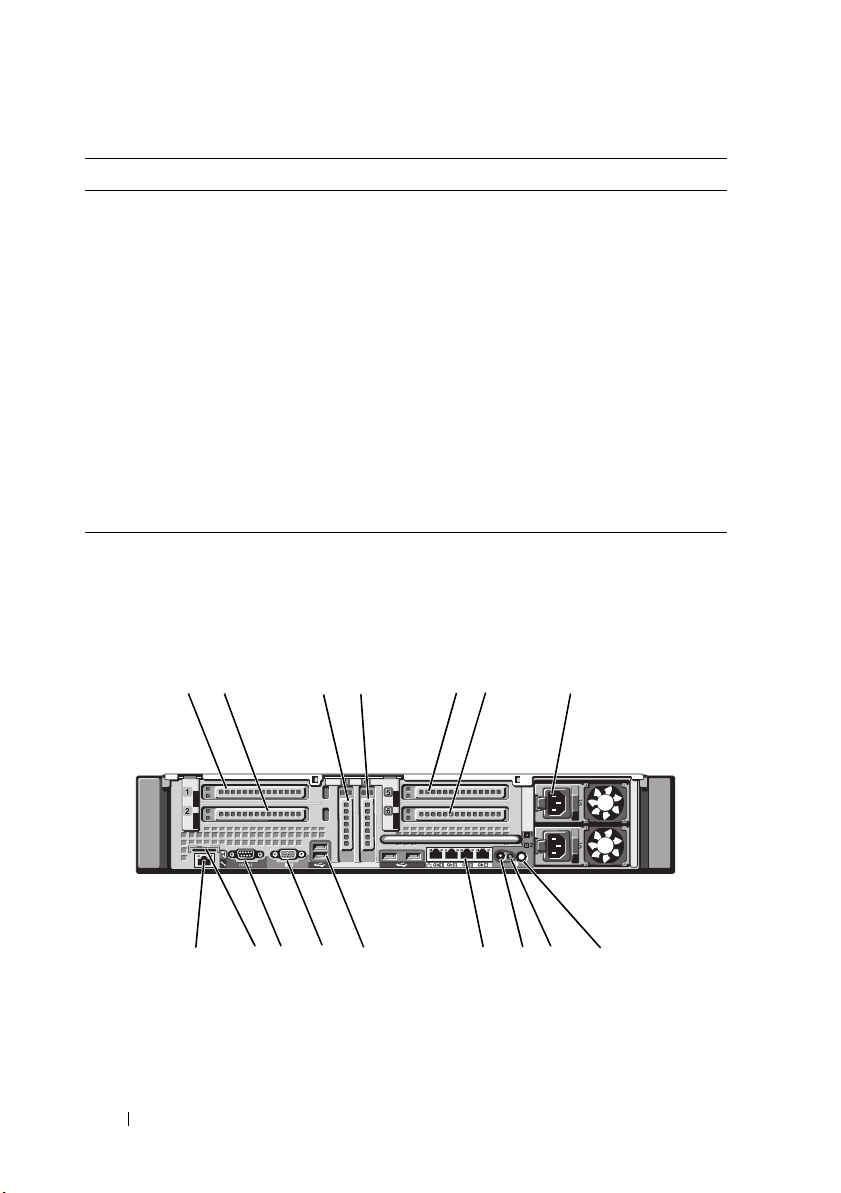
Drive-Status Indicator Pattern (RAID Only) Condition
7
16
15 14
13
12 11
10
9
1
8
2
6
534
Blinks green two times per second Identify drive/preparing for removal
Off Drive ready for insertion or removal
NOTE: The drive status indicator remains off
until all hard drives are initialized after system
power is applied. Drives are not ready for
insertion or removal during this time.
Blinks green, amber, and off Drive predicted failure
Blinks amber four times per second Drive failed
Blinks green slowly Drive rebuilding
Steady green Drive online
Blinks green 3 seconds, amber
3 seconds, and off 6 seconds
Rebuild aborted
Back-Panel Features and Indicators
Figure 1-3. Back-Panel Features and Indicators
18 About Your System
Page 19

Item Indicator, Button, or
Connector
1 PCIe slot 1 PCI Express (Generation 2) x8 link
2 PCIe slot 2 PCI Express (Generation 2) x4 link
3 PCIe slot 3 PCI Express (Generation 2) x8 link
4 PCIe slot 4 PCI Express (Generation 2) x8 link
5 PCIe slot 5 PCI Express (Generation 2) x8 link
6 PCIe slot 6 PCI Express (Generation 2) x8 link
7 Power supplies (2) 1100 W power supplies.
8 System identification
button
9System status
indicator
10 System identification
connector
11 Ethernet connectors
(4)
Icon Description
expansion slot (24.13 cm [9.5"] length).
expansion slot (low-profile 24.13 cm
[9.5"] maximum length, with a standard
height bracket).
expansion slot (low-profile 24.13 cm
[9.5"] length).
expansion slot (low-profile 24.13 cm
[9.5"] length).
expansion slot (24.13 cm [9.5"] length).
expansion slot (24.13 cm [9.5"] length).
The identification buttons on the front
and back panels can be used to locate a
particular system within a rack. When
one of these buttons is pushed, the LCD
panel on the front and the system status
indicator on the back blink until one of
the buttons is pushed again.
Lights blue during normal system
operation.
Lights amber when the system needs
attention due to a problem.
Connects the optional system status
indicator assembly through the optional
cable management arm.
Integrated 10/100/1000 NIC connectors.
About Your System 19
Page 20

Item Indicator, Button, or
Connector
12 USB connectors (4) Connect USB devices to the system. The
13 Video connector Connects a monitor to the system.
14 Serial connector Connects a serial device to the system.
Icon Description
ports are USB 2.0-compliant.
15 VFlash media slot
(optional)
16 iDRAC6 Enterprise
port (optional)
Connects an external SD memory card
for the optional iDRAC6 Enterprise
card.
Dedicated management port for the
optional iDRAC6 Enterprise card.
Guidelines for Connecting External Devices
• Turn off power to the system and external devices before attaching a new
external device. Turn on any external devices before turning on the system
(unless the documentation for the device specifies otherwise).
• Ensure that the appropriate driver for the attached device has been
installed on the system.
• If it is necessary to enable ports on your system, see
Setup Program and UEFI Boot Manager
" on page 55
"Using the System
.
20 About Your System
Page 21
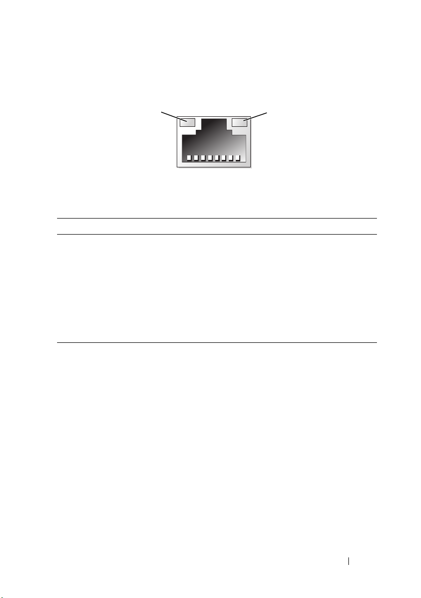
NIC Indicator Codes
1
2
1 link indicator 2 activity indicator
Indicator Indicator Code
Link and activity
indicators are off
Link indicator is green The NIC is connected to a valid network link at
Link indicator is amber The NIC is connected to a valid network link at 10 or
Activity indicator is
green blinking
The NIC is not connected to the network.
1000 Mbps.
100 Mbps.
Network data is being sent or received.
Power Indicator Codes
The power supplies have indicators that show whether power is present or
whether a power fault has occurred.
• Not lit—AC power is not connected.
• Green—In standby mode, a green light indicates that a valid AC source is
connected to the power supply and that the power supply is operational.
When the system is on, a green light also indicates that the power supply is
providing DC power to the system.
• Amber—Indicates a problem with the power supply.
About Your System 21
Page 22
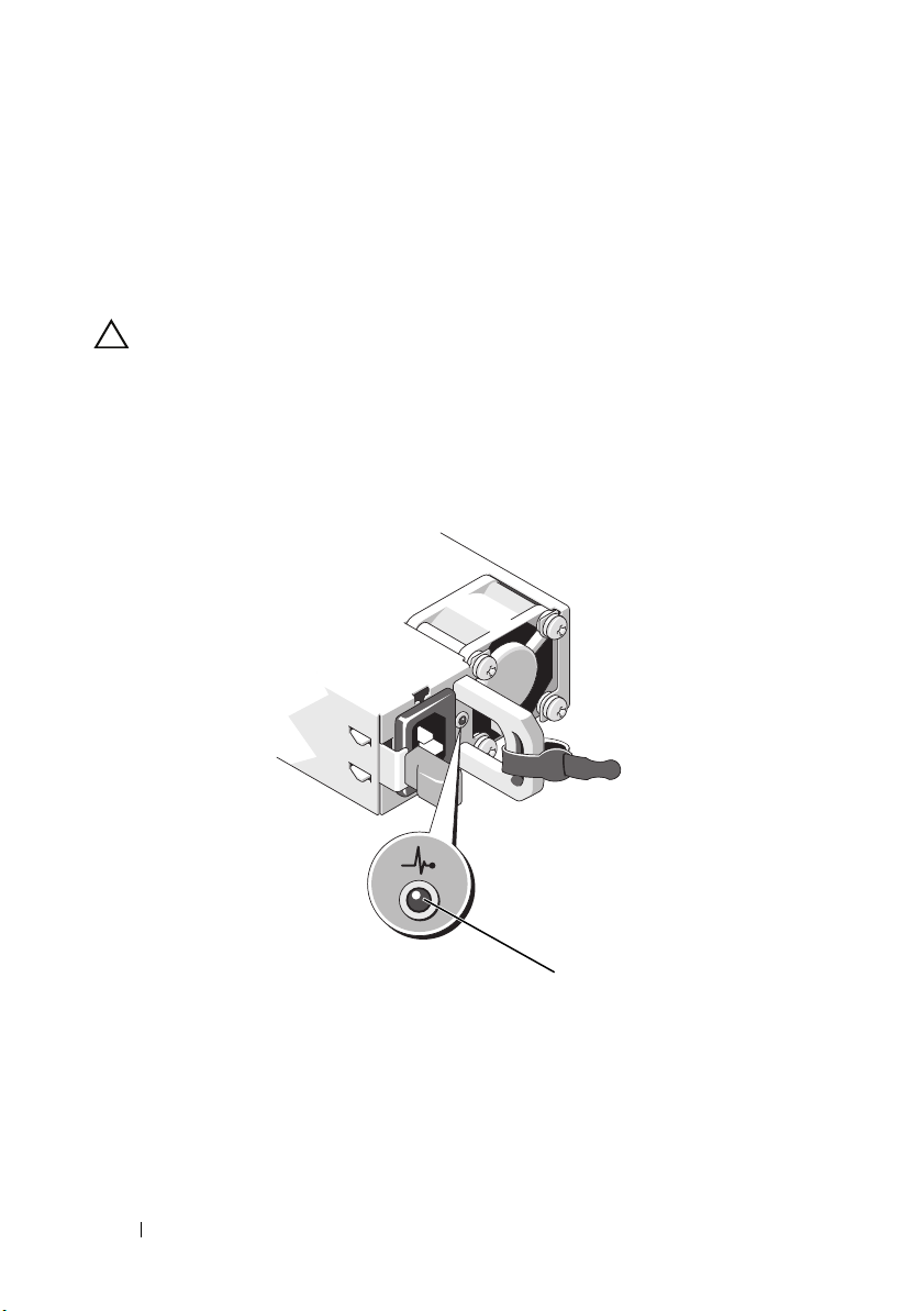
• Alternating green and amber—When hot-adding a power supply, this
1
indicates that the power supply is mismatched with the other power
supply (a high output power supply and an energy smart power supply are
installed in the same system). Replace the power supply that has the
flashing indicator with a power supply that matches the capacity of the
other installed power supply.
CAUTION: When correcting a power supply mismatch, replace only the power
supply with the flashing indicator. Swapping the opposite power supply to make a
matched pair can result in an error condition and unexpected system shutdown. To
change from a High Output configuration to an Energy Smart configuration or vice
versa, you must power down the system.
Figure 1-4. Power Supply Status Indicator
1 power supply status indicator
22 About Your System
Page 23

LCD Status Messages
The LCD messages consist of brief text messages that refer to events recorded
in the System Event Log (SEL). For information on the SEL and configuring
system management settings, see the OpenManage™ Server Administrator
documentation at support.dell.com/manuals.
NOTE: If your system fails to boot, press the System ID button for at least 5 seconds
until an error code appears on the LCD. Record the code, then see "Getting Help" on
page 183.
Viewing Status Messages
If a system error occurs, the LCD screen turns amber. Press the Select button
to view the list of errors or status messages. Press the left and right buttons to
highlight an error number, and press Select to view the error.
Removing LCD Status Messages
For faults associated with sensors, such as temperature, voltage, fans, and so
on, the LCD message is automatically removed when that sensor returns to a
normal state. For other faults, you must take action to remove the message
from the display:
• Clear the SEL—You can perform this task remotely, but you will lose the
event history for the system.
• Power cycle—Turn off the system and disconnect it from the electrical
outlet; wait approximately 10 seconds, reconnect the power cable, and
restart the system.
NOTE: The following LCD status messages are displayed in the Simple format. See
"Setup Menu" on page 16 to select the format in which the messages are displayed.
About Your System 23
Page 24

Table 1-1. LCD Status Messages
Code Text Causes Corrective Actions
E1000 Failsafe
voltage
error.
Contact
support.
E1114 Ambient Temp
exceeds
allowed
range.
E1116 Memory
disabled,
temp above
range. Power
cycle AC.
E1119 Chipset #
temp out of
range. Check
motherboard
heatsinks.
E1210 Motherboard
battery
failure.
Check
battery.
Check the system event log
for critical failure events.
Ambient temperature
reached a point outside the
allowed range.
Memory exceeded allowable
temperature and has been
disabled to prevent damage
to the components.
Chipset temperature
reached a point outside the
allowed range.
CMOS battery is missing or
the voltage is outside the
allowable range.
Remove AC power to the
system for 10 seconds and
restart the system.
If the problem persists,
see "Getting Help" on
page 183.
See "Troubleshooting
System Cooling
Problems" on page 155.
Remove AC power to the
system for 10 seconds and
restart the system.
See "Troubleshooting
System Cooling
Problems" on page 155. If
the problem persists, see
"Getting Help" on
page 183.
See "Troubleshooting
System Cooling
Problems" on page 155.
See "Troubleshooting the
System Battery" on
page 154.
24 About Your System
Page 25

Code Text Causes Corrective Actions
E1211 RAID
Controller
battery
failure.
Check
battery.
E1216 3.3 V
Regulator
failure.
Reseat PCIe
cards.
E1219 Disk
Backplane
power
failure.
Check BP
power cable.
E122C CPU Power
Fault. Power
cycle AC.
E122D Memory
Regulator #
Failed.
Reseat DIMMs.
E122E On-board
regulator
failed. Call
support.
RAID battery is either
missing, bad, or unable to
recharge due to thermal
issues.
3.3 V voltage regulator
failed.
Storage backplane voltage
regulator failed.
A power fault was detected
when powering up the
processor(s).
One of the memory voltage
regulators failed.
One of the on-board voltage
regulators failed.
Reseat the RAID battery
connector. See "RAID
Battery (Optional)" on
page 116 and
"Troubleshooting System
Cooling Problems" on
page 155.
Remove and reseat the
PCIe expansion cards. If
the problem persists, see
"Troubleshooting
Expansion Cards" on
page 164.
Remove and reconnect
the backplane power
cable.
If the problem persists,
see "Getting Help" on
page 183.
Remove AC power to the
system for 10 seconds and
restart the system.
If the problem persists,
see "Getting Help" on
page 183.
Reseat the memory
modules. See
"Troubleshooting System
Memory" on page 157.
Remove AC power to the
system for 10 seconds and
restart the system.
If the problem persists,
see "Getting Help" on
page 183.
About Your System 25
Page 26

Code Text Causes Corrective Actions
E1243 CPU # VCORE
Regulator
failure.
Contact
Support.
E1310 Fan ## RPM
exceeding
range. Check
fan.
E1313 Fan
redundancy
lost. Check
fans.
E1314 Critical
system
cooling loss.
Check fans.
E1410 System Fatal
Error
detected.
E1414 CPU # temp
exceeding
range. Check
CPU heatsink.
Processor voltage regulator
failed.
RPM of specified fan is
outside the intended
operating range.
The system is no longer fan
redundant. Another fan
failure would put the system
at risk of over-heating.
All fans have been removed
from the system.
A fatal system error
detected.
Specified processor is out of
acceptable temperature
range.
Reseat the processor. See
"Troubleshooting the
Processors" on page 166.
If the problem persists,
see "Getting Help" on
page 183.
See "Troubleshooting
System Cooling
Problems" on page 155.
Check LCD for additional
scrolling messages. See
"Troubleshooting a Fan"
on page 156.
Ensure that the fans are
properly installed. See
"Troubleshooting a Fan"
on page 156.
Check LCD for additional
scrolling messages.
Remove AC power to the
system for 10 seconds and
restart the system.
If the problem persists,
see "Getting Help" on
page 183.
Ensure that the processor
heat sinks are properly
installed. See
"Troubleshooting the
Processors" on page 166
and "Troubleshooting
System Cooling
Problems" on page 155.
26 About Your System
Page 27

Code Text Causes Corrective Actions
E1418 CPU # not
detected.
Check CPU is
seated
properly.
E141C Unsupported
CPU
configuration
. Check CPU
or BIOS
revision.
E141F CPU #
protocol
error. Power
cycle AC.
E1420 CPU Bus
parity error.
Power cycle
AC.
E1421 CPU #
initialization
error. Power
cycle AC.
E1422 CPU # machine
check error.
Power cycle
AC.
Specified processor is
missing or bad and the
system is in an unsupported
configuration.
Processors are in an
unsupported configuration.
The system BIOS reported a
processor protocol error.
The system BIOS reported a
processor bus parity error.
The system BIOS reported a
processor initialization error.
The system BIOS reported a
machine check error.
Ensure that the specified
processor is properly
installed. See
"Troubleshooting the
Processors" on page 166.
Ensure that your
processors match and
conform to the type
described in the processor
technical specifications
outlined in your system’s
Getting Started Guide.
Remove AC power to the
system for 10 seconds and
restart the system.
If the problem persists,
see "Getting Help" on
page 183.
Remove AC power to the
system for 10 seconds and
restart the system.
If the problem persists,
see "Getting Help" on
page 183.
Remove AC power to the
system for 10 seconds and
restart the system.
If the problem persists,
see "Getting Help" on
page 183.
Remove AC power to the
system for 10 seconds and
restart the system.
If the problem persists,
see "Getting Help" on
page 183.
About Your System 27
Page 28

Code Text Causes Corrective Actions
E1610 Power Supply
# (#### W)
missing.
Check power
supply.
E1614 Power Supply
# (#### W)
error. Check
power supply.
E1618 Predictive
failure on
Power Supply
# (#### W).
Check PSU.
E161C Power Supply
# (#### W)
lost AC
power. Check
PSU cables.
E1620 Power Supply
# (#### W) AC
power error.
Check PSU
cables.
E1624 Lost power
supply
redundancy.
Check PSU
cables.
Specified power supply
removed or is missing from
the system.
Specified power supply
failed.
A power supply fan failure,
an over-temperature
condition, or power supply
communication error caused
the predictive warning of an
impending power supply
failure.
Specified power supply is
installed but lost its AC
input.
Specified power supply's AC
input is outside the
allowable range.
The power supply subsystem
is no longer redundant. If
the remaining power supply
fails, the system will shut
down.
See "Troubleshooting
Power Supplies" on
page 155.
See "Troubleshooting
Power Supplies" on
page 155.
See "Troubleshooting
Power Supplies" on
page 155.
Check the AC power
source for the specified
power supply. If the
problem persists, see
"Troubleshooting Power
Supplies" on page 155.
Check the AC power
source for the specified
power supply. If the
problem persists, see
"Troubleshooting Power
Supplies" on page 155.
See "Troubleshooting
Power Supplies" on
page 155.
28 About Your System
Page 29

Code Text Causes Corrective Actions
E1629 Power
required >
PSU wattage.
Check PSU and
config.
E1631 System power
draw exceeded
threshold.
Contact
support.
E1632 FailSafe
event.
Contact
support.
E1710 I/O channel
check error.
Review &
clear SEL.
The system configuration
requires more power than
the power supplies can
provide, even with
throttling.
Processor and memory
throttling is not sufficient to
keep system power
consumption below the
maximum safe level with
the current power supply
configuration.
The processors and memory
have been throttled to keep
system power consumption
below the maximum safe
level with current power
supply configuration.
The system BIOS reported
an I/O channel check.
Turn off power to the
system, check if adequate
power is supplied to the
system. See the Getting
Started Guide for
information on the
System power
requirements.
Remove AC power to the
system for 10 seconds and
restart the system.
If the problem persists,
see "Getting Help" on
page 183.
Remove AC power to the
system for 10 seconds and
restart the system.
If the problem persists,
see "Getting Help" on
page 183.
Check the SEL for more
information and then
clear the SEL. Remove
AC power to the system
for 10 seconds and restart
the system.
If the problem persists,
see "Getting Help" on
page 183.
About Your System 29
Page 30

Code Text Causes Corrective Actions
E1711 PCI parity
error on Bus
## Device ##
Function ##.
PCI parity
error on Slot
#. Review &
clear SEL.
E1712 PCI system
error on Bus
## Device ##
Function ##.
PCI system
error on Slot
#. Review &
clear SEL.
E1714 Unknown
error. Review
& clear SEL.
The system BIOS reported a
PCI parity error on a
component that resides in
PCI configuration space at
bus ##, device ##,
function ##.
The system BIOS reported a
PCI parity error on a
component that resides in
the specified slot.
The system BIOS reported a
PCI system error on a
component that resides in
PCI configuration space at
bus ##, device ##,
function ##.
The system BIOS reported a
PCI system error on a
component that resides in
the specified slot.
The system BIOS
determined there has been
an error in the system, but is
unable to determine its
origin.
Remove and reseat the
PCIe expansion cards. If
the problem persists, see
"Troubleshooting
Expansion Cards" on
page 164.
Remove and reseat the
PCIe expansion cards. If
the problem persists, see
"Troubleshooting
Expansion Cards" on
page 164.
Remove and reseat the
PCIe expansion cards. If
the problem persists, see
"Troubleshooting
Expansion Cards" on
page 164.
Remove and reseat the
expansion-card riser that
provides the specified slot.
See "Expansion Cards and
Expansion-Card Risers"
on page 105. If the
problem persists, the riser
card or system board is
faulty. See "Getting Help"
on page 183.
Check the SEL for more
information and then
clear the SEL. Remove
AC power to the system
for 10 seconds and restart
the system.
If the problem persists,
see "Getting Help" on
page 183.
30 About Your System
Page 31

Code Text Causes Corrective Actions
E1715 Fatal I/O
Error. Review
& clear SEL.
E1716 Chipset IERR
Bus ## Dev ##
Function ##.
Review &
clear SEL.
E1717 CPU #
internal
error. Review
& clear SEL.
The system BIOS
determined there has been a
fatal error in the system.
The system BIOS reported a
chipset internal error that
resides in bus ##, device
##, function ##.
The system BIOS
determined that the
specified processor has had
an internal error.
Check the SEL for more
information, and then
clear the SEL. Remove
AC power to the system
for 10 seconds, and restart
the system.
If the problem persists,
see "Getting Help" on
page 183.
Check the SEL for more
information, and then
clear the SEL. Remove
AC power to the system
for 10 seconds, and restart
the system.
If the problem persists,
see "Getting Help" on
page 183.
Check the SEL for more
information, and then
clear the SEL. Remove
AC power to the system
for 10 seconds, and restart
the system.
If the problem persists,
see "Getting Help" on
page 183.
About Your System 31
Page 32

Code Text Causes Corrective Actions
E171F PCIe fatal
error on Bus
## Device ##
Function ##.
PCIe fatal
error on Slot
#. Review &
clear SEL.
E1810 Hard drive ##
fault. Review
& clear SEL.
E1812 Hard drive ##
removed.
Check drive.
E1A11 PCI Riser
hardware &
configuration
mismatch.
Reconfigure.
E1A12 PCI Riser not
detected.
Check Riser.
The system BIOS reported a
PCIe fatal error on a
component that resides in
PCI configuration space at
bus ##, device ##,
function ##.
The system BIOS reported a
PCIe fatal error on a
component that resides in
the specified slot.
The specified hard drive
experienced a fault.
The specified hard drive is
removed from the system.
PCIe risers are not
configured correctly. Some
invalid configurations
prevent the system from
powering on.
One or both of the PCIe
risers are missing. This
prevents the system from
powering on.
Remove and reseat the
PCIe expansion cards. If
the problem persists, see
"Troubleshooting
Expansion Cards" on
page 164.
Remove and reseat the
expansion-card riser. See
"Expansion Cards and
Expansion-Card Risers"
on page 105. If the
problem persists, the riser
card or system board is
faulty. See "Getting Help"
on page 183.
See "Troubleshooting a
Hard Drive" on page 162.
Information only.
Reinstall the expansioncard riser. See "Expansion
Cards and ExpansionCard Risers" on page 105.
If the problem persists,
the riser card or system
board is faulty. See
"Getting Help" on
page 183.
Reinstall the missing riser.
See "Installing ExpansionCard Riser 1" on page 111
and "Installing ExpansionCard Riser 2" on page 113.
32 About Your System
Page 33

Code Text Causes Corrective Actions
E1813 Internal Dual
SD Module
Card #
failed. Check
SD card.
E1814 Internal SD
Module Card #
writeprotected.
Check SD
card.
E1815 Internal Dual
SD Module
redundancy
lost. Check
SD cards.
E1A14 SAS cable A
failure.
Check
connection.
E1A15 SAS cable B
failure.
Check
connection.
E1A1D Control panel
USB cable not
detected.
Check cable.
The internal dual SD
module card failed.
The internal dual SD
module card is writeprotected and cannot be
used.
The internal dual SD
module bootable media is
no longer redundant.
SAS cable A is missing or
bad.
SAS cable B is missing or
bad.
USB cable to the control
panel is missing or bad.
Reseat the internal dual
SD module card.
If the problem persists,
see "Getting Help" on
page 183.
Change the write-protect
switch setting on SD card.
Reseat the internal dual
SD module card.
If the problem persists,
see "Getting Help" on
page 183.
Reseat the cable. If the
problem persists, replace
the cable.
If the problem persists,
see "Getting Help" on
page 183.
Reseat the cable. If the
problem persists, replace
the cable.
If the problem persists,
see "Getting Help" on
page 183
Reseat the cable. If the
problem persists, replace
the cable.
If the problem persists,
see "Getting Help" on
page 183.
About Your System 33
Page 34

Code Text Causes Corrective Actions
E2010 Memory not
detected.
Inspect
DIMMs.
E2011 Memory
configuration
failure.
Check DIMMs.
E2012 Memory
configured
but unusable.
Check DIMMs.
E2013 BIOS unable
to shadow
memory. Check
DIMMs.
E2014 CMOS RAM
failure.
Power cycle
AC.
E2015 DMA
Controller
failure.
Power cycle
AC.
E2016 Interrupt
Controller
failure.
Power cycle
AC.
No memory detected in the
system.
Memory detected, but is not
configurable. Error detected
during memory
configuration.
Memory configured, but is
unusable.
The system BIOS failed to
copy its flash image into
memory.
CMOS failure. CMOS RAM
not functioning properly.
DMA controller failure. Remove AC power to the
Interrupt controller failure. Remove AC power to the
Install memory or reseat
the memory modules. See
"Installing Memory
Modules" on page 95 or
"Troubleshooting System
Memory" on page 157.
See "Troubleshooting
System Memory" on
page 157.
See "Troubleshooting
System Memory" on
page 157.
See "Troubleshooting
System Memory" on
page 157.
Remove AC power to the
system for 10 seconds and
restart the system.
If the problem persists,
see "Getting Help" on
page 183.
system for 10 seconds and
restart the system.
If the problem persists,
see "Getting Help" on
page 183.
system for 10 seconds and
restart the system.
If the problem persists,
see "Getting Help" on
page 183.
34 About Your System
Page 35

Code Text Causes Corrective Actions
E2017 Timer refresh
failure.
Power cycle
AC.
E2018 Programmable
Timer error.
Power cycle
AC.
E2019 Parity error.
Power cycle
AC.
E201A SuperIO
failure.
Power cycle
AC.
E201B Keyboard
controller
error. Power
cycle AC.
E201C SMI
initialization
failure.
Power cycle
AC.
Timer refresh failure. Remove AC power to the
system for 10 seconds and
restart the system.
If the problem persists,
see "Getting Help" on
page 183.
Programmable interval
timer error.
Parity error. Remove AC power to the
SIO failure. Remove AC power to the
Keyboard controller failure. Remove AC power to the
System management
interrupt (SMI)
initialization failure.
Remove AC power to the
system for 10 seconds and
restart the system.
If the problem persists,
see "Getting Help" on
page 183.
system for 10 seconds and
restart the system.
If the problem persists,
see "Getting Help" on
page 183.
system for 10 seconds and
restart the system.
If the problem persists,
see "Getting Help" on
page 183.
system for 10 seconds and
restart the system.
If the problem persists,
see "Getting Help" on
page 183.
Remove AC power to the
system for 10 seconds and
restart the system.
If the problem persists,
see "Getting Help" on
page 183.
About Your System 35
Page 36

Code Text Causes Corrective Actions
E201D Shutdown test
failure.
Power cycle
AC.
E201E POST memory
test failure.
Check DIMMs.
E2020 CPU
configuration
failure.
Check screen
message.
E2021 Incorrect
memory
configuration.
Review User
Guide.
E2022 General
failure
during POST.
Check screen
message.
E2026 Memory
initialization
error.
Contact
support.
BIOS shutdown test failure. Remove AC power to the
system for 10 seconds and
restart the system.
If the problem persists,
see "Getting Help" on
page 183.
BIOS POST memory test
failure.
Processor configuration
failure.
Incorrect memory
configuration.
General failure after video. Check screen for specific
Invalid memory
configuration.
See "Troubleshooting
System Memory" on
page 157.
If the problem persists,
see "Getting Help" on
page 183.
Check screen for specific
error messages. See
"Troubleshooting the
Processors" on page 166.
Check screen for specific
error messages. See
"Troubleshooting System
Memory" on page 157.
error messages.
Ensure that the memory
modules are installed in a
valid configuration. See
"General Memory Module
Installation Guidelines"
on page 92. See "Getting
Help" on page 183.
36 About Your System
Page 37

Code Text Causes Corrective Actions
E2110 Multibit
Error on DIMM
##. Reseat
DIMM.
E2111 SBE log
disabled on
DIMM ##.
Reseat DIMM.
E2112 Memory spared
on DIMM ##.
Power cycle
AC.
I1910 Intrusion
detected.
Check chassis
cover.
I1911 LCD Log Full.
Check SEL to
review all
Errors.
I1912 SEL full.
Review &
clear log.
The memory module in slot
"##" has had a multi-bit
error (uncorrectable).
The system BIOS disabled
memory single-bit error
(correctable) logging and
will not log any more SBEs
until the system is rebooted.
"##" represents the memory
module implicated by the
BIOS.
The system BIOS spared the
memory because it
determined that the
memory has too many
errors.
System cover removed. Replace the chassis cover
LCD overflow message. A
maximum of ten error
messages can display
sequentially on the LCD.
The eleventh message
instructs the user to check
the SEL for details on the
events.
The SEL is full of events
and is unable to log any
more.
Reseat the memory
module in its socket.
If the problem persists,
see "Troubleshooting
System Memory" on
page 157.
Reseat the memory
module in its socket.
If the problem persists,
see "Troubleshooting
System Memory" on
page 157.
Remove AC power to the
system for 10 seconds and
restart the system.
If the problem persists,
see "Troubleshooting
System Memory" on
page 157.
or ensure the chassis cover
is properly installed. See
"Closing the System" on
page 79.
Check the SEL for details
on the events.
Remove AC power to the
system for 10 seconds or
clear the SEL.
Check the SEL for more
information and then
clear the SEL.
About Your System 37
Page 38

Code Text Causes Corrective Actions
W1100 CPU VCORE
Regulator
temp
exceeding
range. Check
fans.
W1102 Mem Voltage
Regulator
temp
exceeding
range. Check
fans
W1228 RAID
Controller
battery
capacity <
24hr.
W1630 Power supply
redundancy
degraded.
Check PSU
cables.
The regulator temperature
reached a point outside the
allowed range.
The regulator temperature
reached a point outside the
allowed range.
Warns predictively that the
RAID battery has less than
24 hours of charge left.
The power supply subsystem
is no longer fully redundant.
See "Troubleshooting
System Cooling
Problems" on page 155. If
the problem persists, see
"Getting Help" on
page 183.
See "Troubleshooting
System Cooling
Problems" on page 155. If
the problem persists, see
"Getting Help" on
page 183.
Allow RAID battery to
charge to greater than 24
hours of sustained charge.
If problem persists,
replace the RAID battery.
See "RAID Battery
(Optional)" on page 116.
Reseat the power supplies.
See "Troubleshooting
Power Supplies" on
page 155.
If the problem persists,
see "Getting Help" on
page 183.
NOTE: For the full name of an abbreviation or acronym used in this table, see the
Glossary at support.dell.com/manuals.
38 About Your System
Page 39

System Messages
System messages appear on the screen to notify you of a possible problem
with the system.
NOTE: If you receive a system message not listed in the table, check the
documentation for the application that is running when the message appears or the
operating system's documentation for an explanation of the message and
recommended action.
Table 1-2. System Messages
Message Causes Corrective Actions
Alert! iDRAC6 not
responding.
Rebooting.
Alert! iDRAC6 not
responding.
Power required
may exceed PSU
wattage.
Alert!
Continuing
system boot
accepts the risk
that system may
power down
without warning.
The iDRAC6 is not
responding to BIOS
communication either
because it is not functioning
properly or has not
completed initialization. The
system will reboot.
The iDRAC6 has stopped
responding.
The iDRAC6 was remotely
reset while the system was
booting.
After AC recovery, the
iDRAC6 takes longer than
normal to boot.
Wait for the system to
reboot.
Remove AC power to the
system for 10 seconds and
restart the system.
About Your System 39
Page 40

Message Causes Corrective Actions
Alert! Node
Interleaving
disabled! Memory
configuration
does not support
Node
Interleaving.
Alert! Power
required exceeds
PSU wattage.
Check PSU and
system
configuration.
Alert!
Continuing
system boot
accepts the risk
that system may
power down
without warning.
Alert! Redundant
memory disabled!
Memory
configuration
does not support
redundant
memory.
The memory configuration
has changed (for example, a
memory module has failed)
so that node interleaving
cannot be supported. The
system will run but without
node interleaving.
The system configuration of
processor(s), memory
modules, and expansion
cards may not be supported
by the power supplies.
Redundant memory was
enabled in the system setup
program, but the current
configuration does not
support redundant memory.
A memory module may be
faulty.
Ensure that the memory
modules are installed in a
configuration that supports
node interleaving. Check
other system messages for
additional information for
possible causes. For memory
configuration information,
see "General Memory
Module Installation
Guidelines" on page 92. If
the problem persists, see
"Troubleshooting System
Memory" on page 157.
If any system components
were just upgraded, return
the system to the previous
configuration. If the system
boots without this warning,
then the replaced
component(s) are not
supported with this power
supply. If Energy Smart
power supplies are installed,
replace them with the High
Output power supplies to use
the components. See "Power
Supplies" on page 87.
Check the memory modules
for failure. See
"Troubleshooting System
Memory" on page 157. Reset
the memory setting, if
appropriate. See "Using the
System Setup Program and
UEFI Boot Manager" on
page 55.
40 About Your System
Page 41

Message Causes Corrective Actions
Alert! System
fatal error
during previous
boot.
BIOS
MANUFACTURING
MODE detected.
MANUFACTURING
MODE will be
cleared before
the next boot.
System reboot
required for
normal
operation.
BIOS Update
Attempt Failed!
Caution!
NVRAM_CLR jumper
is installed on
system board.
CPU set to
minimum
frequency.
An error caused the system to
reboot.
System is in manufacturing
mode.
Remote BIOS update
attempt failed.
NVRAM_CLR jumper is
installed in the clear setting.
CMOS has been cleared.
The processor speed may be
intentionally set lower for
power conservation.
Check other system
messages for additional
information for possible
causes.
Reboot to take the system
out of manufacturing mode.
Retry the BIOS update. If
the problem persists, see
"Getting Help" on page 183.
Move the NVRAM_CLR
jumper to the default
position (pins 3 and 5). See
Figure 6-1 for jumper
location. Restart the system
and re-enter the BIOS
settings. See "Using the
System Setup Program and
UEFI Boot Manager" on
page 55.
If not an intentional setting,
check any other system
messages for possible causes.
About Your System 41
Page 42

Message Causes Corrective Actions
CPUs with
different cache
sizes detected.
CPUs with
different core
sizes detected!
System halted.
CPUs with
different power
rating detected!
System halted.
Current boot mode
is set to UEFI.
Please ensure
compatible
bootable media is
available. Use
the system setup
program to change
the boot mode as
needed.
Decreasing
available
memory.
Embedded NICx and
NICy:
OS NIC=<ENABLED
|DISABLED>,
Management
Shared NIC=
<ENABLED
|DISABLED>
Mismatched processors have
been installed in the system.
The system failed to boot
because UEFI boot mode is
enabled in BIOS and the
boot operating system is nonUEFI.
Faulty or improperly installed
memory modules.
The operating system NIC
interface is set in BIOS. The
Management Shared NIC
interface is set in
management tools.
Ensure that all processors
have the same cache size,
number of cores, and power
rating. Ensure that the
processors are properly
installed. See "Processors" on
page 123.
Ensure that the boot mode is
set correctly and that the
proper bootable media is
available. See "Using the
System Setup Program and
UEFI Boot Manager" on
page 55.
Reseat the memory modules.
See "Troubleshooting System
Memory" on page 157.
Check the system
management software or the
System Setup program for
NIC settings. If a problem is
indicated, see
"Troubleshooting a NIC" on
page 151.
42 About Your System
Page 43

Message Causes Corrective Actions
Error 8602 Auxiliary Device
Failure. Verify
that mouse and
keyboard are
securely
attached to
correct
connectors.
Gate A20 failure. Faulty keyboard controller;
General failure. The operating system is
Invalid
configuration
information please run SETUP
program.
Invalid PCIe card
found in the
Internal_Storage
slot!
Keyboard
controller
failure.
Keyboard data
line failure.
Keyboard stuck
key failure.
Mouse or keyboard cable is
loose or improperly
connected.
Defective mouse or keyboard. Ensure that the mouse or
faulty system board.
unable to carry out the
command.
An invalid system
configuration caused a
system halt.
The system halted because
an invalid PCIe expansion
card is installed in the
dedicated storage controller
slot.
Faulty keyboard controller;
faulty system board.
Keyboard cable connector is
improperly connected or the
keyboard is defective.
Reseat the mouse or
keyboard cable.
keyboard is operational. See
"Troubleshooting a USB
Device" on page 150.
See "Getting Help" on
page 183.
This message is usually
followed by specific
information. Note the
information, and take the
appropriate action to resolve
the problem.
Run the System Setup
program and review the
current settings. See "Using
the System Setup Program
and UEFI Boot Manager" on
page 55.
Remove the PCIe expansion
card and install the
integrated storage controller
in the dedicated slot. See
"Integrated Storage
Controller Card" on
page 113.
See "Getting Help" on
page 183.
Reseat the keyboard cable. If
the problem persists, see
"Troubleshooting a USB
Device" on page 150.
About Your System 43
Page 44

Message Causes Corrective Actions
Keyboard fuse has
failed.
Local keyboard
may not work
because all user
accessible USB
ports are
disabled. If
operating
locally, power
cycle the system
and enter system
setup program to
change settings.
Manufacturing
mode detected.
Memory tests
terminated by
keystroke.
No boot device
available.
Overcurrent detected at the
keyboard connector.
The USB ports are disabled
in the system BIOS.
System is in manufacturing
mode.
POST memory test was
terminated by pressing the
spacebar.
Faulty or missing optical
drive subsystem, hard drive,
or hard-drive subsystem, or
non-bootable USB key
installed.
See "Getting Help" on
page 183.
Power down and restart the
system using the power
button, and then enter the
System Setup program to
enable the USB port(s). See
"Entering the System Setup
Program" on page 56.
Reboot to take the system
out of manufacturing mode.
Information only.
Use a bootable USB key, CD,
or hard drive. If the problem
persists, see
"Troubleshooting an Internal
USB Key" on page 159,
"Troubleshooting a USB
Device" on page 150,
"Troubleshooting an Optical
Drive" on page 161, and
"Troubleshooting a Hard
Drive" on page 162. See
"Using the System Setup
Program and UEFI Boot
Manager" on page 55 for
information on setting the
order of boot devices.
44 About Your System
Page 45

Message Causes Corrective Actions
No boot sector on
hard drive.
No timer tick
interrupt.
PCI BIOS failed
to install.
PCIe Training
Error: Expected
Link Width is x,
Actual Link Width
is y.
Plug & Play
Configuration
Error.
Incorrect configuration
settings in System Setup
program, or no operating
system on hard drive.
Faulty system board. See "Getting Help" on
PCIe device BIOS (Option
ROM) checksum failure
detected during shadowing.
Cables to expansion card(s)
loose; faulty or improperly
installed expansion card(s).
Faulty or improperly installed
PCIe card in the specified
slot.
Error encountered in
initializing PCIe device;
faulty system board.
Check the hard-drive
configuration settings in the
System Setup program. See
"Using the System Setup
Program and UEFI Boot
Manager" on page 55. If
necessary, install the
operating system on your
hard drive. See your
operating system
documentation.
page 183.
Reseat the expansion card(s).
Ensure that all appropriate
cables are securely connected
to the expansion card(s). If
the problem persists, see
"Troubleshooting Expansion
Cards" on page 164.
Reseat the PCIe card in the
specified slot number. See
"Troubleshooting Expansion
Cards" on page 164. If the
problem persists, see
"Getting Help" on page 183.
Install the NVRAM_CLR
jumper in the clear position
(pins 1 and 3) and reboot the
system. See Figure 6-1 for
jumper location. If the
problem persists, see
"Troubleshooting Expansion
Cards" on page 164.
About Your System 45
Page 46

Message Causes Corrective Actions
Read fault.
Requested sector
not found.
SATA Port x
device not found.
SATA port x
device autosensing error.
SATA port x
device
configuration
error.
SATA port 0
device failure.
Requested sector
not found.
Seek error.
Seek operation
failed.
Shutdown
failure.
The operating system cannot
read from the hard drive,
optical drive, or USB device,
the system could not find a
particular sector on the disk,
or the requested sector is
defective.
There is no device connected
to the specified SATA port.
The drive connected to the
specified SATA port is faulty.
Faulty hard drive, USB
device, or USB medium.
General system error. See "Getting Help" on
Replace the optical medium,
USB medium or device.
Ensure that the SAS
backplane, USB, or SATA
cables are properly
connected. See
"Troubleshooting a USB
Device" on page 150,
"Troubleshooting an Optical
Drive" on page 161, or
"Troubleshooting a Hard
Drive" on page 162 for the
appropriate drive(s) installed
in your system.
Information only.
Replace the faulty drive.
Replace the USB medium or
device. Ensure that the USB
or SAS backplane cables are
properly connected. See
"Troubleshooting a USB
Device" on page 150 or
"Troubleshooting a Hard
Drive" on page 162 for the
appropriate drive(s) installed
in your system.
page 183.
46 About Your System
Page 47

Message Causes Corrective Actions
The amount of
system memory has
changed.
Time-of-day
clock stopped.
Time-of-day not
set - please run
SETUP program.
Timer chip
counter 2 failed.
TPM or TCM
configuration
operation
honored. System
will now reset.
Memory has been added or
removed or a memory
module may be faulty.
Faulty battery or faulty chip. See "Troubleshooting the
Incorrect Time or Date
settings; faulty system
battery.
Faulty system board. See "Getting Help" on
A Trusted Platform Module
(TPM) or China Trusted
Platform Module (TCM)
configuration command has
been entered. The system
will reboot and execute the
command.
If memory has been added or
removed, this message is
informative and can be
ignored. If memory has not
been added or removed,
check the SEL to determine
if single-bit or multi-bit
errors were detected and
replace the faulty memory
module. See
"Troubleshooting System
Memory" on page 157.
System Battery" on page 154.
Check the Time and Date
settings. See "Using the
System Setup Program and
UEFI Boot Manager" on
page 55. If the problem
persists, replace the system
battery. See "System Battery"
on page 130.
page 183.
Information only.
About Your System 47
Page 48

Message Causes Corrective Actions
TPM or TCM
configuration
operation is
pending. Press
(I) to Ignore OR
(M) to Modify to
allow this change
and reset the
system.
WARNING:
Modifying could
prevent
security.
TPM or TCM
failure.
Unable to launch
System Services
image. System
halted!
Unexpected
interrupt in
protected mode.
This message displays during
system restart after a TPM or
TCM configuration
command has been entered.
User interaction is required
to proceed.
A TPM or TCM function has
failed.
System halted after <F10>
keystroke because System
Services image is either
corrupted in the system
firmware or has been lost due
to system board replacement.
The iDRAC6 Enterprise card
flash memory may be
corrupted.
Improperly seated memory
modules or faulty
keyboard/mouse controller
chip.
Enter I or M to proceed.
See "Getting Help" on
page 183.
Restart the system and
update Lifecycle Controller
by running the Lifecycle
Controller Dell Update
Package (DUP). For more
information, see the Dell
Update Packages User's Guide
at
support.dell.com/manuals.
If the system still reports the
same error, run the Lifecycle
Controller Repair Package.
Follow the instruct i o n s
provided with the package to
complete the installation.
Reseat the memory modules.
See "Troubleshooting System
Memory" on page 157. If the
problem persists, see
"Getting Help" on page 183.
48 About Your System
Page 49

Message Causes Corrective Actions
Unsupported CPU
combination.
Unsupported CPU
stepping
detected.
Unsupported DIMM
detected. The
following DIMM
has been
disabled: x
Unsupported
memory
configuration.
DIMM mismatch
across slots
detected:
x,x,...
Warning: A fatal
error has caused
system reset!
Please check the
system event log!
Warning: Front
Control Panel is
not installed.
Warning! No micro
code update
loaded for
processor n.
Processor(s) not supported
by the system.
Invalid memory
configuration. The system
will run but with the
specified memory module
disabled.
Invalid memory
configuration. Memory
modules are mismatched in
the specified slots.
A fatal system error occurred
and caused the system to
reboot.
The control panel is not
installed or has a faulty cable
connection.
Micro code update failed. Update the BIOS. See
Install a supported processor
or processor combination.
See "Processors" on page 123.
Ensure that the memory
modules are installed in a
valid configuration. See
"General Memory Module
Installation Guidelines" on
page 92.
Ensure that the memory
modules are installed in a
valid configuration. See
"General Memory Module
Installation Guidelines" on
page 92.
Check the SEL for
information that was logged
during the error. See the
applicable troubleshooting
section in "Troubleshooting
Your System" on page 149 for
any faulty components
specified in the SEL.
Install the control panel, or
check the cable connections
between the control panel
board and the system board.
See "Control Panel
Assembly" on page 138.
"Getting Help" on page 183.
About Your System 49
Page 50

Message Causes Corrective Actions
Warning! Power
required exceeds
PSU wattage.
Check PSU and
system
configuration.
Warning!
Performance
degraded. CPU and
memory set to
minimum
frequencies to
meet PSU wattage.
System will
reboot.
Write fault.
Write fault on
selected drive.
Incorrect memory
configuration
CPU n.
The system configuration of
processor(s), memory
modules, and expansion
cards may not be supported
by the power supplies.
Faulty USB device, USB
medium, optical drive
assembly, hard drive, or harddrive subsystem.
The DIMM group for CPU n
is incorrectly configured and
caused the system to halt.
If any system components
were just upgraded, return
the system to the previous
configuration. If the system
boots without this warning,
then the replaced
component(s) are not
supported with this power
supply. If low wattage power
supplies are installed, replace
them with High Output
power supplies to use the
components. See "Power
Supplies" on page 87.
Replace the USB medium or
device. Ensure that the USB,
SAS backplane, or SATA
cables are properly
connected. See
"Troubleshooting a USB
Device" on page 150,
"Troubleshooting an Internal
USB Key" on page 159, and
"Troubleshooting a Hard
Drive" on page 162.
See "General Memory
Module Installation
Guidelines" on page 92, for
memory configuration
information. If the problem
persists, see
"Troubleshooting System
Memory" on page 157.
50 About Your System
Page 51

Message Causes Corrective Actions
HyperTransport
error caused a
system reset!
Please check the
system event log
for details!
Warning:
Following faulty
DIMMs are
ignored:
DIMM n1 n2
Total memory size
is reduced.
Warning:
Following faulty
DIMMs are
disabled:
DIMM n1 n2
Total memory size
is reduced.
Warning: The
installed memory
configuration is
not optimal. For
more information
on valid memory
configurations,
please see the
system
documentation on
the technical
support web site.
A fatal system error occurred
and caused the system to
reboot.
Faulty or improperly seated
memory module(s). Check
both DIMMs in the same
channel for a possible fault.
Faulty or improperly seated
memory module(s). Check
both DIMMs in the same
channel for a possible fault.
Invalid memory
configuration. The system
will run but with reduced
functionality.
Check the SEL for
information that is logged
during the error. See the
applicable troubleshooting
section in "Troubleshooting
Your System" on page 149,
for any faulty components
specified in the SEL.
See "Troubleshooting Your
System" on page 149.
See "Troubleshooting Your
System" on page 149.
Ensure that the memory
modules are installed in a
valid configuration. See
"General Memory Module
Installation Guidelines" on
page 92. If the problem
persists, see
"Troubleshooting System
Memory" on page 157.
NOTE: For the full name of an abbreviation or acronym used in this table, see the
Glossary at support.dell.com/manuals.
About Your System 51
Page 52

Warning Messages
A warning message alerts you to a possible problem and prompts you to
respond before the system continues a task. For example, before you format a
hard drive, a message will warn you that you may lose all data on the hard
drive. Warning messages usually interrupt the task and require you to respond
by typing y (yes) or n (no).
NOTE: Warning messages are generated by either the application or the operating
system. For more information, see the documentation that accompanied the
operating system or application.
Diagnostics Messages
The system diagnostic utilities may issue messages if you run diagnostic tests
on your system. See "Running the System Diagnostics" on page 169 for more
information about system diagnostics.
Alert Messages
Systems management software generates alert messages for your system. Alert
messages include information, status, warning, and failure messages for drive,
temperature, fan, and power conditions. For more information, see the
OpenManage™ Server Administrator documentation at
support.dell.com/manuals.
52 About Your System
Page 53
Other Information You May Need
WARNING: See the safety and regulatory information that shipped with your
system. Warranty information may be included within this document or as a
separate document.
• The rack documentation included with your rack solution describes how to
install your system into a rack.
•The
• Dell systems management application documentation at
• Any media that ships with your system that provides documentation and
Getting Started Guide
up your system, and technical specifications.
support.dell.com/manuals
the systems management software.
tools for configuring and managing your system, including those
pertaining to the operating system, system management software, system
updates, and system components that you purchased with your system.
NOTE: Always check for updates on support.dell.com/manuals and read the
updates first because they often supersede information in other documents.
provides an overview of system features, setting
provides information about installing and using
About Your System 53
Page 54

54 About Your System
Page 55

2
Using the System Setup Program and UEFI Boot Manager
The System Setup program enables you to manage your system hardware and
specify BIOS-level options. From the System Setup program, you can:
• Change the NVRAM settings after you add or remove hardware
• View the system hardware configuration
• Enable or disable integrated devices
• Set performance and power management thresholds
• Manage system security
Choosing the System Boot Mode
The System Setup program also enables you to specify the boot mode for
installing your operating system:
• BIOS boot mode (the default) is the standard BIOS-level boot interface.
• UEFI boot mode is an enhanced 64-bit boot interface based on Unified
Extensible Firmware Interface (UEFI) specifications that overlays the
system BIOS. See "Entering the UEFI Boot Manager" on page 66 for more
information on this interface.
You must select the boot mode in the Boot Mode field of the "Boot Settings
Screen" on page 61 of the System Setup program. After specifying the boot
mode, proceed to install your operating system in that mode. Thereafter, boot
the system to the same boot mode (BIOS or UEFI) to access the installed
operating system. Trying to boot the operating system from another boot
mode causes the system to halt immediately at startup.
NOTE: Operating systems must be UEFI-compatible (for example, Microsoft®
Windows Server
and 32-bit operating systems do not support UEFI and can only be installed from the
BIOS boot mode.
®
2008 x64 version) to be installed from the UEFI boot mode. DOS
Using the System Setup Program and UEFI Boot Manager 55
Page 56
Entering the System Setup Program
1
Turn on or restart your system.
2
Press <F2> immediately after you see the following message:
<F2> = System Setup
If your operating system begins to load before you press <F2>, allow the
system to finish booting, and then restart your system and try again.
Responding to Error Messages
If an error message appears while the system is booting, make a note of the
message. See "System Messages" on page 39 for an explanation of the message
and suggestions for correcting errors.
NOTE: After installing a memory upgrade, it is normal for your system to display a
message the first time you start your system.
Using the System Setup Program Navigation Keys
Keys Action
Up arrow or <Shift><Tab> Moves to the previous field.
Down arrow or <Tab> Moves to the next field.
Spacebar, <+>, <
right arrows
<Esc> Exits the System Setup program and restarts the
<F1> Displays the System Setup program
–>, left and
Cycles through the settings in a field. In some
fields, you can also type the appropriate value.
system if any changes were made.
's help file.
NOTE: For most of the options, any changes that you make are recorded but do not
take effect until you restart the system.
56 Using the System Setup Program and UEFI Boot Manager
Page 57
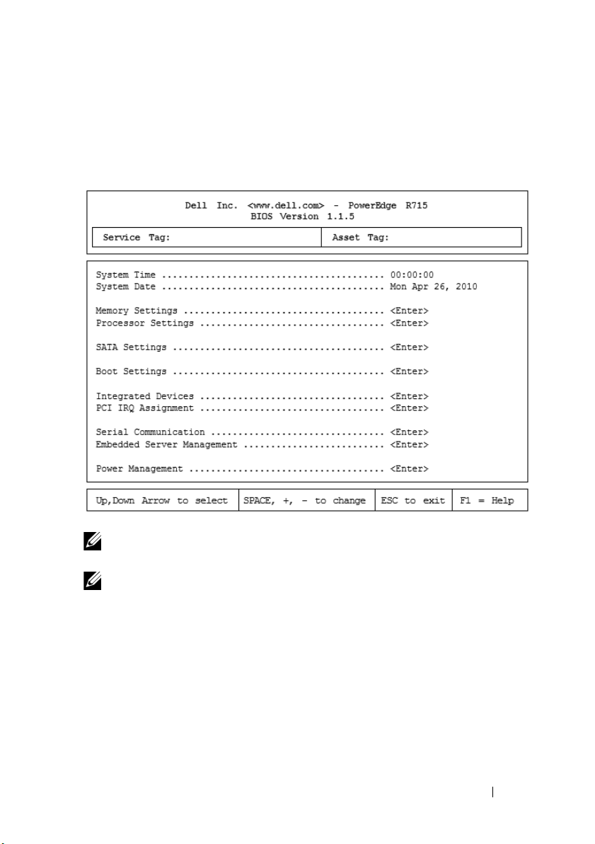
System Setup Options
Main Screen
NOTE: The options for the System Setup program change based on the system
configuration.
NOTE: The System Setup program defaults are listed under their respective options
in the following sections, where applicable.
Using the System Setup Program and UEFI Boot Manager 57
Page 58

Option Description
System Time Sets the time on the system's internal clock.
System Date Sets the date on the system's internal calendar.
Memory Settings Displays information related to installed memory.
See "Memory Settings Screen" on page 59.
Processor Settings Displays information related to processors (speed,
cache size, and so on). See "Processor Settings Screen"
on page 60.
SATA Settings Displays a screen to enable or disable the integrated
SATA controller and ports. See "SATA Settings Screen"
on page 61.
Boot Settings Displays a screen to specify the boot mode (BIOS or
UEFI). For BIOS boot mode, you can also specify the
boot devices. See "Boot Settings Screen" on page 61.
Integrated Devices Displays a screen to enable or disable integrated device
controllers and ports, and to specify related features
and options. See "Integrated Devices Screen" on
page 62.
PCI IRQ Assignment Displays a screen to change the IRQ assigned to each of
the integrated devices on the PCI bus, and any installed
expansion card that requires an IRQ. See "PCI IRQ
Assignments Screen" on page 63.
Serial Communication Displays a screen to enable or disable the serial ports
and specify related features and options. See "Serial
Communication Screen" on page 63.
Power Management Enables you to manage power usage of the processor(s),
fans, and memory modules with preconfigured or
customized settings. See "Power Management Screen"
on page 64.
System Security Displays a screen to configure the system password and
setup password features. See "System Security Screen"
on page 65, "Using the System Password" on page 69,
and "Using the Setup Password" on page 71 for more
information.
58 Using the System Setup Program and UEFI Boot Manager
Page 59

Option Description
Keyboard NumLock
(On default)
Report Keyboard Errors
(
Report
default)
F1/F2 Prompt on Error
(Enabled default)
Determines whether your system starts up with the
NumLock mode activated on 101- or 102-key keyboards
(does not apply to 84-key keyboards).
Enables or disables reporting of keyboard errors during
the POST. Select Report for host systems that have
keyboards attached. Select Do Not Report to suppress
all error messages relating to the keyboard or keyboard
controller during POST. This setting does not affect the
operation of the keyboard itself if a keyboard is attached
to the system.
Enables the system to halt on errors during POST,
which allows the user to observe events that may scroll
by unnoticed during normal POST. The user can press
<F1> to continue or <F2> to enter the System
Setup program.
CAUTION: When setting this option to Disabled,
the system does not halt if an error occurs during
POST. Any critical errors are displayed and logged
in the system event log.
Memory Settings Screen
Option Description
System Memory Size Displays the amount of system memory.
System Memory Type Displays the type of system memory.
System Memory Speed Displays the system memory speed.
Video Memory Displays the amount of video memory.
System Memory Testing
(Enabled default)
Redundant Memory
(Disabled default)
Node Interleaving
(Disabled default)
Specifies whether system memory tests are run at system
boot. Options are Enabled and Disabled.
Specifies whether redundant memory is enabled on the
system. Options are Enabled and Disabled.
If this field is Enabled, memory interleaving is supported
if a symmetric memory configuration is installed.
Using the System Setup Program and UEFI Boot Manager 59
Page 60

Processor Settings Screen
Option Description
64-bit Specifies if the processor(s) support 64-bit extensions.
Core Speed Displays the processor clock speed.
Bus Speed Displays the processor bus speed.
Hyper Transport
Tec h no l og y ( HT3 default)
HT Assist (Enabled
default)
CPU Virtualization
Te ch n o lo g y
(Enabled default)
DRAM Prefetcher
(Enabled default)
Hardware Prefetch
Tra i ni ng o n S of tw ar e
Prefetch
Hardware Prefetcher
(Enabled default)
Execute Disable
(Enabled default)
Number of Cores per
Processor (All default)
C1E
(Enabled default)
Processor X FamilyModel-Stepping
Displays the HyperTransport link speed, and depending
upon the system, this field may be read-only. HT3
capable systems ship with HT3 by default.
Enables or disables the HT Assist.
Enabled permits virtualization software to use the
virtualization technology incorporated in the processor.
NOTE: Disable this feature if your system does not run
virtualization software.
Enables or disables the DRAM prefetcher.
Enables or disables the Hardware prefetcher training on
software prefetcher.
Enables or disables the hardware prefetcher.
Enables or disables Execute Disable Memory Protection
Te ch n ol og y.
Controls the number of enabled cores in each processor.
When set to Enabled, the processor(s) can switch to a
minimum performance state when idle.
Displays the family and model number of each processor.
A submenu displays the core speed, the amount of cache
memory, and the number of cores of the processor(s).
60 Using the System Setup Program and UEFI Boot Manager
Page 61
SATA Settings Screen
Option Description
Embedded SATA
(ATA default)
Port A
(Auto default)
ATA Mode enables the integrated SATA controller. Off
disables the controller.
Auto enables BIOS support for the device attached to
SATA port A. Off disables BIOS support for the device.
Boot Settings Screen
Option Description
Boot Mode
(BIOS default)
Boot Sequence If Boot Mode is set to BIOS, this field tells the system
Hard-Disk Drive
Sequence
USB Flash Drive
Emulation Type
Boot Sequence Retry
(Disabled default)
CAUTION: Switching the boot mode could prevent
the system from booting if the operating system was
not installed in the same boot mode.
If the operating system supports Unified Extensible
Firmware Interface, you can set this option to UEFI.
Setting this field to BIOS allows compatibility with nonUEFI operating systems.
NOTE: Setting this field to UEFI disables the Boot
Sequence, Hard-Disk Drive Sequence, and USB Flash Drive
Emulation Type fields.
where the operating system files needed for startup are
located. If Boot Mode is set to UEFI, you can access the
UEFI boot manager utility by rebooting the system and
pressing <F11> when prompted to do so.
Determines the order in which the BIOS attempts to boot
from hard drives in the system during system startup.
Determines the emulation type for a USB flash drive.
If Boot Mode is set to UEFI, this field is disabled.
If this field is enabled and the system has failed to boot,
the system reattempts to boot after 30 seconds.
Using the System Setup Program and UEFI Boot Manager 61
Page 62

Integrated Devices Screen
Option Description
Integrated SAS Controller
(Enabled default)
User Accessible USB Ports
(All Ports On default)
Internal USB Port
(On default)
Internal SD Card Port
(On default)
Redundancy
(Mirror default)
Embedded NIC1
(Enabled with PXE
default)
Embedded NIC2
(Enabled default)
Embedded Gb NICx
(Enabled default)
MAC Address Displays the MAC address for the integrated 10/100/1000
Embedded NIC3 and
NIC4
(Enabled default)
OS Watchdog Timer
(Disabled default)
Embedded Video
Controller
(Enabled default)
Enables or disables the integrated SAS controller.
Enables or disables the user accessible USB ports.
Options are All Ports On, Only Back Ports On, and All
Ports Off.
Enables or disables the internal USB port.
Enables or disables the internal SD card port.
Enables or disables the mirror mode for Internal Dual SD
Modules (if installed).
Enables or disables the operating system interface of the
embedded NICs. The NICs can also be accessed through
the system's management controller.
Enables or disables the operating system interface of the
embedded NICs. The NICs can also be accessed through
the system's management controller.
Enables or disables the integrated NIC. Options are
Enabled and Enabled with PXE. PXE support allows the
system to boot from the network.
NIC.
Enables or disables the operating system interface of the
embedded NICs. The NICs can also be accessed through
the system's management controller.
Aids recovery of the operating system, if your system
stops responding. If set to Enabled, the operating system
is allowed to initialize the timer.
Enables/disables BIOS support for the Embedded Video
Controller.
62 Using the System Setup Program and UEFI Boot Manager
Page 63

PCI IRQ Assignments Screen
Option Description
<PCIe device> Use the <+> and <-> keys to manually select an IRQ
for a given device, or select Default to allow the BIOS to
select an IRQ value at system startup.
Serial Communication Screen
Option Description
Serial Communication
(On without Console
Redirection default)
Serial Port Address
(Serial Device 1=COM1,
Serial Device2=COM2
default)
External Serial Connector
(Serial Device1 default)
Failsafe Baud Rate
(115200 default)
Remote Terminal Type
(VT 100/VT220 default)
Redirection After Boot
(Enabled default)
Selects whether the serial communication devices
(Serial Device 1 and Serial Device 2) are enabled in
BIOS. BIOS console redirection can also be enabled and
the port address to be used can be specified.
Options are On without Console Redirection, On with
Console Redirection via COM1, On with Console
Redirection via COM2, and Off.
Sets the serial port addresses for the two serial devices.
NOTE: Only Serial Device 2 can be used for Serial Over
LAN (SOL). To use console redirection by SOL, configure
the same port address for console redirection and the
serial device.
Specifies whether Serial Device 1, Serial Device 2, or
Remote Access Device has access to the external
serial connector.
NOTE: Only Serial Device 2 can be used for Serial Over
LAN (SOL). To use console redirection by SOL, configure
the same port address for console redirection and the
serial device.
Displays the failsafe baud rate used for console
redirection. BIOS attempts to determine the baud rate
automatically. This failsafe baud rate is used only if the
attempt fails. This rate should not be adjusted.
Sets the remote console terminal type, either
VT100/VT220 or ANSI.
Enables or disables BIOS console redirection when the
operating system is loaded.
Using the System Setup Program and UEFI Boot Manager 63
Page 64

Power Management Screen
Option Description
Power Management
(OS Control default)
CPU Power and
Perfor mance
Management
Fan Power and
Perfor mance
Management
Memory Power and
Perfor mance
Management
Options are OS Control, Active Power Controller,
Custom, or Maximum Performance. For all but the
Custom setting, the BIOS pre-configures the power
settings on this screen as follows:
•
OS Control
fan power to
to
Maximum Performance
performance information is passed from the system
BIOS to the operating system for control. The operating
system sets the processor performance based on
processor utilization.
Active Power Controller
•
System DBPM
the memory power to
BIOS sets the processor performance based on processor
utilization.
Maximum Performance
•
Performance
If you select Custom, you can configure each option
independently.
Options are OS DBPM, System DBPM, Maximum
Performance, or Minimum Power.
Options are Maximum Performance or Minimum Power.
Options are Maximum Performance, a specified
frequency, or Minimum Power.
sets the processor power to
Minimum Power
, the fan power to
.
, and the memory power
. In this setting, all processor
sets the processor power to
Minimum Power
Maximum Performance
sets all fields to
OS DBPM
. The
Maximum
, the
, and
64 Using the System Setup Program and UEFI Boot Manager
Page 65

System Security Screen
Option Description
System Password Displays the current status of the password security
feature and allows a new system password assignment
and verification.
NOTE: See Using the "Using the System Password" on
page 69 for more information.
Setup Password Restricts access to the System Setup program by using a
setup password.
NOTE: See "Using the System Password" on page 69 for
more information.
Password Status
(Unlocked default)
Power Button
(Enabled default)
NMI Button
(Disabled default)
AC Power Recovery
(Last default)
When Setup Password is assigned and this field is
Locked, the system password cannot be changed or
disabled at system start-up.
See "Using the System Password" on page 69 for more
information.
If Enabled, the power button can turn the system's power
off and on. On an
system performs an orderly shutdown before power is
turned off.
When Disabled, the button can only turn on system power.
CAUTION: Use the NMI button only if directed to
do so by qualified support personnel or by the
operating system's documentation. Pressing this
button halts the operating system and displays a
diagnostic screen.
ACPI-compliant operating system, the
Enables or disables the NMI feature.
Determines how the system reacts when power is restored. If
set to Last, the system returns to the last power state. On
turns on the system after power is restored. Off allows the
system to remain off after power is restored.
Using the System Setup Program and UEFI Boot Manager 65
Page 66
Option Description
AC Power Recovery
Delay
User Defined Delay The delay defined by the user.
Determines when the system restarts after power is
restored. Options are Immediate, Random (a random
value of 30 to 240 seconds), or a user-defined value of 30
to 240 seconds.
Exit Screen
Press <Esc> to exit the System Setup program; the Exit screen displays:
• Save Changes and Exit
• Discard Changes and Exit
• Return to Setup
Entering the UEFI Boot Manager
NOTE: Operating systems must be 64-bit UEFI-compatible (for example, Microsoft
Windows Server 2008 x64 version) to be installed from the UEFI boot mode. DOS and
32-bit operating systems can only be installed from the BIOS boot mode.
NOTE: The Boot Mode must be set to UEFI in the System Setup program to access
the UEFI Boot Manager.
The UEFI Boot Manager enables you to:
• Add, delete, and arrange boot options
• Access the System Setup program and BIOS-level boot options
without rebooting
1
Turn on or restart your system.
2
Press <F11> after you see the following message:
<F11> = UEFI Boot Manager
NOTE: The system does not respond until the USB keyboard is active.
If your operating system begins to load before you press <F11>, allow the
system to finish booting, and then restart your system and try again.
66 Using the System Setup Program and UEFI Boot Manager
Page 67

Using the UEFI Boot Manager Navigation Keys
Keys Action
Up arrow Moves to and highlights the previous field.
Down arrow Moves to and highlights the next field.
Spacebar, <Enter>, <+>,
<
–>
<Esc> Refreshes the UEFI Boot Manager screen, or
<F1> Displays the UEFI Boot Manager help file.
Cycles through the settings in a field.
returns to the UEFI Boot Manager screen from the
other program screens.
UEFI Boot Manager Screen
Option Description
Continue The system attempts to boot to devices starting with
the first item in the boot order. If the boot attempt fails,
the system continues with the next item in the boot
order until the boot is successful or no more boot
options are found.
<Boot options> Displays the list of available boot options (marked with
asterisks). Select the boot option you wish to use and
press Enter.
NOTE: If you hot-add a boot device, press <ESC> to
refresh the list of boot options.
UEFI Boot Settings Enables you to add, delete, enable, or disable boot options;
change boot order; or execute a one-time boot option.
System Utilities Enables you to access the System Setup program,
System Services (Unified Server Configurator [USC]),
Diagnostics, and BIOS-level boot options.
Using the System Setup Program and UEFI Boot Manager 67
Page 68

UEFI Boot Settings Screen
Option Description
Add Boot Option Adds a new boot option.
Delete Boot Option Deletes an existing boot option.
Enable/Disable Boot
Option
Change Boot Order Changes the order of the boot option list.
One-Time Boot From File Sets a one-time boot option not included in the boot
Disables and enables a boot option in the boot option list.
option list.
System Utilities Screen
Option Description
System Setup Accesses the System Setup program without rebooting.
System Services Restarts the system and access the Lifecycle
Controller, which allows you to run utilities such as
system diagnostics.
BIOS Boot Manager Accesses the BIOS-level boot options list without
rebooting. This option enables you to conveniently
switch to BIOS boot mode if you need to boot to a
device with a non-UEFI operating system, such as a
bootable DOS media with diagnostics software.
Reboot System Restarts the system.
68 Using the System Setup Program and UEFI Boot Manager
Page 69
System and Setup Password Features
NOTE: For a forgotten password, see "Disabling a Forgotten Password" on
page 181.
Your system is shipped without the system password feature enabled. Operate
the system only with system password protection.
CAUTION: The password features provide a basic level of security for the data on
your system.
CAUTION: Anyone can access the data stored on your system if the system is
running and unattended.
Using the System Password
When a system password is assigned, the system prompts for the password
during start up.
Assigning a System Password
Before assigning a system password, enter the System Setup program and
check the System Password option.
When a system password is assigned, System Password is Enabled. If
Password Status is Unlocked, you can change the system password. If Locked,
you cannot change the system password. Disabling the password jumper on
the system board sets System Password to Disabled, and you cannot change
or enter a new system password.
When a system password is not assigned and the password jumper on the
system board is in the enabled position, System Password is Not Enabled and
Password Status is Unlocked.
To assign a system password:
1
Veri fy t ha t
2
Highlight the
3
Type your new system password.
You can use up to 32 characters in your password.
Password Status
System Password
is
Unlocked
.
option and press <Enter>.
As you type, placeholders appear in the field.
Using the System Setup Program and UEFI Boot Manager 69
Page 70
The password assignment is not case-sensitive. Certain key combinations
are invalid and if you enter one, the system beeps. To erase a character,
press <Backspace> or the left-arrow key.
NOTE: To escape from the field without assigning a system password, press
<Enter> to move to another field, or press <Esc> prior to completing step 5.
4
Press <Enter>.
5
To confirm your password, type it a second time and press <Enter>.
System Password
changes to
Enabled
. Exit the System Setup program and
begin using your system.
6
Either reboot the system now for the password protection to take effect or
continue working.
NOTE: Password protection does not take effect until the system reboots.
Using Your System Password to Secure Your System
NOTE: If you have assigned a setup password (see "Using the Setup Password" on
page 71), the system accepts your setup password as an alternate system
password.
When Password Status is Unlocked, you have the option to leave the
password security enabled or to disable password security.
To leave the password security enabled:
1
Turn on or reboot your system by pressing <Ctrl><Alt><Delete>.
2
Type your password and press <Enter>.
To disable the password security:
Turn on or reboot your system by pressing <Ctrl><Alt><Delete>.
1
2
Type your password and press <Ctrl><Enter>.
When Password Status is Locked, type the password and press <Enter>
when prompted at reboot.
If an incorrect system password is entered, the system displays a message and
prompts you to re-enter your password. You have three attempts to enter the
correct password. After the third unsuccessful attempt, the system displays an
error message that the system has halted and shuts down.
70 Using the System Setup Program and UEFI Boot Manager
Page 71

Even after you shut down and restart the system, the error message continues
to be displayed until the correct password is entered.
NOTE: You can use the Password Status option in conjunction with the System
Password and Setup Password options to protect your system from unauthorized
changes.
Deleting or Changing an Existing System Password
1
Enter the System Setup program and select the
2
Highlight
Setup Password
, press <Enter> to access the setup password
System Security
.
window. Press <Enter> twice to clear the existing setup password.
The setting changes to
3
If you want to assign a new setup password, perform the steps in "Assigning
Not Enabled
.
a Setup Password" on page 71.
Using the Setup Password
Assigning a Setup Password
You can assign a setup password only when the Setup Password is Not
Enabled. To assign a setup password, highlight the Setup Password option
and press the <+> or <–> key. The system prompts you to enter and verify
the password.
NOTE: The setup password can be the same as the system password. If the two
passwords are different, the setup password can be used as an alternate system
password. The system password cannot be used in place of the setup password.
You can use up to 32 characters in your password.
As you type, placeholders appear in the field.
The password assignment is not case-sensitive. Certain key combinations are
invalid and if you enter one, the system beeps. To erase a character, press
<Backspace> or the left-arrow key.
When you verify the password, the Setup Password changes to Enabled. The
next time you enter the System Setup program, the system prompts you for
the setup password.
A change to the Setup Password option becomes effective immediately
(restarting the system is not required).
Using the System Setup Program and UEFI Boot Manager 71
Page 72

Operating With a Setup Password Enabled
If Setup Password is Enabled, you must enter the correct setup password
before modifying most of the System Setup options.
If you do not enter the correct password in three attempts, the system lets you
view, but not modify, the System Setup screens. The following options are
exceptions: If System Password is not Enabled and is not locked through the
Password Sta tus option, you can assign a system password. You cannot disable
or change an existing system password.
NOTE: You can use the Password Status option in conjunction with the Setup
Password option to protect the system password from unauthorized changes.
Deleting or Changing an Existing Setup Password
1
Enter the System Setup program and select the
2
Highlight
window. Press <Enter> twice to clear the existing setup password.
The setting changes to
3
If you want to assign a new setup password, perform the steps in "Assigning
a Setup Password" on page 71.
Setup Password
Not Enabled
, press <Enter> to access the setup password
.
System Security
.
Embedded System Management
The Lifecycle Controller is an embedded utility that enables systems
management tasks from an embedded environment throughout the
server’s lifecycle.
Lifecycle Controller can be started during the boot sequence and can
function independently of the operating system.
NOTE: Certain platform configurations may not support the full set of features
provided by the Lifecycle Controller.
For more information about setting up the Lifecycle Controller, configuring
hardware and firmware, and deploying the operating system, see the Lifecycle
Controller documentation at support.dell.com/manuals.
72 Using the System Setup Program and UEFI Boot Manager
Page 73

iDRAC6 Configuration Utility
The iDRAC6 Configuration Utility is a pre-boot configuration environment
that allows you to view and set parameters for the iDRAC6 and for the
managed server.
The iDRAC6 Configuration Utility provides the following features:
• Enables fault logging and SNMP alerting
• Provides access to system event log and sensor status
• Functions independently of the system’s operating system
In addition the iDRAC6 Configuration Utility enables you to:
• Configure, enable, or disable the iDRAC6 local area network through the
dedicated iDRAC6 Enterprise card port or the embedded NIC1
• Enable or disable IPMI over LAN
• Enable a LAN Platform Event Trap (PET) destination
• Attach or detach the Virtual Media devices
• Change the administrative user name and password and manage user
privileges
• View System Event Log (SEL) messages or clear messages from the log
• Reset iDRAC6 settings to default
For additional information on using iDRAC6, see the documentation for
iDRAC6 and systems management applications.
Entering the iDRAC6 Configuration Utility
1
Turn on or restart your system.
2
Press <Ctrl><E> when prompted during POST.
If your operating system begins to load before you press <Ctrl><E>,
allow the system to finish booting, and then restart your system and try
again.
Using the System Setup Program and UEFI Boot Manager 73
Page 74

74 Using the System Setup Program and UEFI Boot Manager
Page 75
3
Installing System Components
Recommended Tools
You may need the following items to perform the procedures in this section:
• Key to the system keylock
• #1 and #2 Phillips screwdrivers
• T8 and T10 Torx drivers
•W
rist grounding stra
Inside the System
WARNING: Whenever you need to lift the system, get others to assist you. To
avoid injury, do not attempt to lift the system by yourself.
CAUTION: Many repairs may only be done by a certified service technician.
You should only perform troubleshooting and simple repairs as authorized in
your product documentation, or as directed by the online or telephone service
and support team. Damage due to servicing that is not authorized by Dell is
not covered by your warranty. Read and follow the safety instructions that
came with the product.
p
NOTE: It is recommended that you always use a static mat and static strap while
working on components in the interior of the system.
Installing System Components 75
Page 76
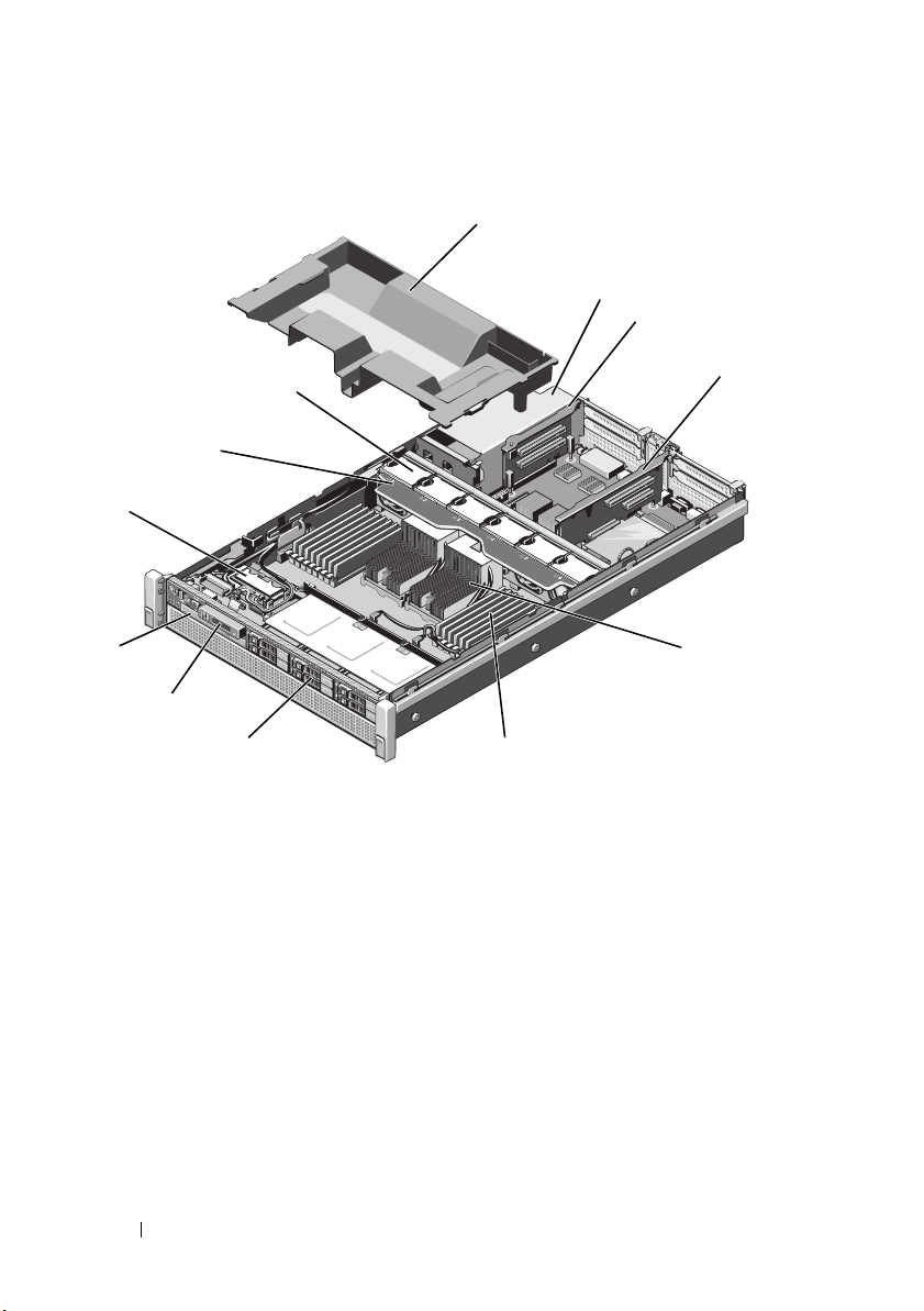
Figure 3-1. Inside the System
2
3
4
5
6
7
8
9
1
0
1
1
2
1
1
1 cooling shroud 2 power supply bays (2)
3 expansion card riser 2 4 expansion card riser 1
5 heat sinks (2) 6 memory modules (16)
7 hard drives (up to 6) 8 control panel
9 optical drive (optional) 10 internal Dual SD module
11 cooling fan assembly 12 cooling fans (6)
76 Installing System Components
Page 77
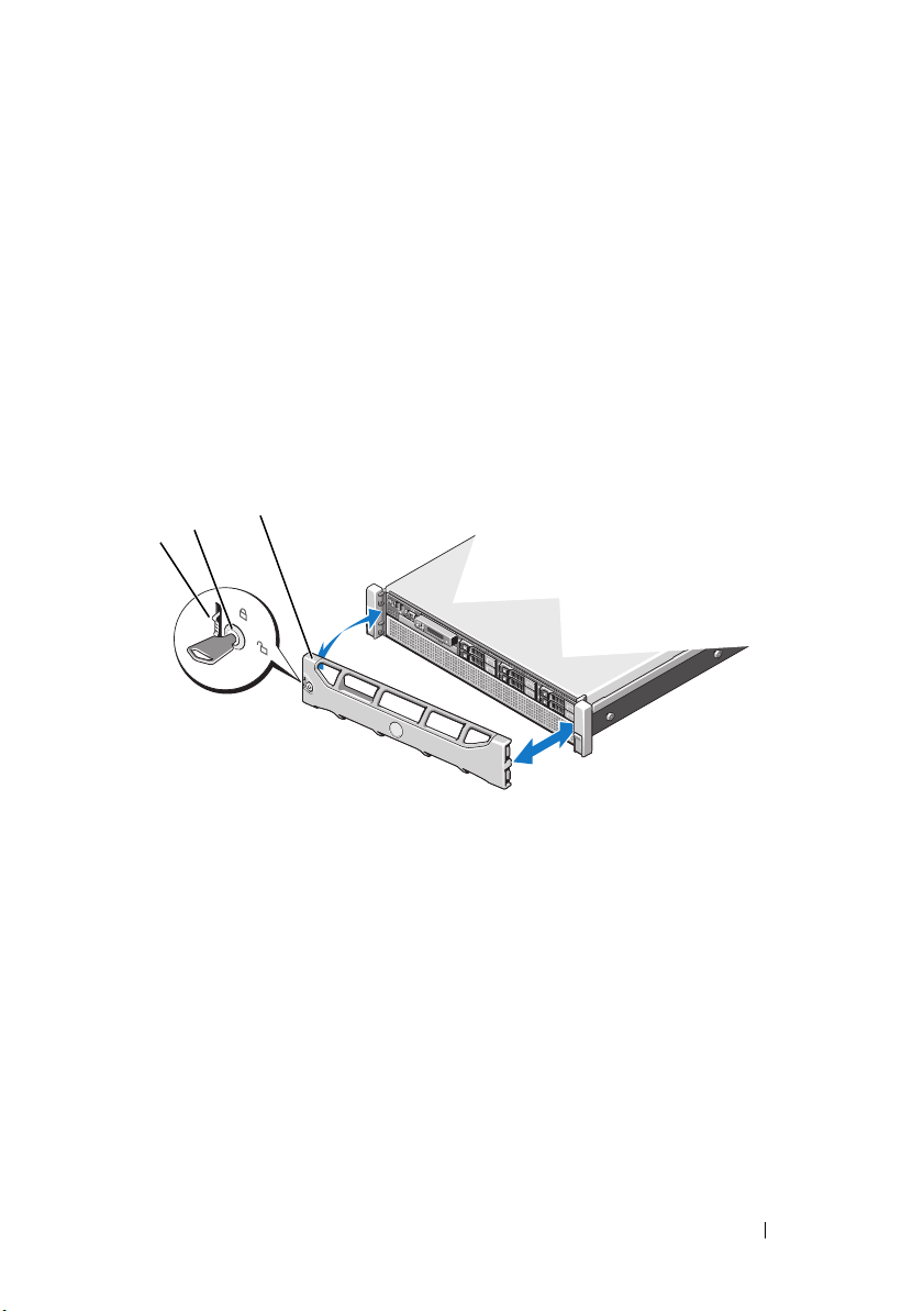
Front Bezel (Optional)
1
2
3
Removing the Front Bezel
1
Unlock the keylock at the left end of the bezel.
2
Lift up the release latch next to the keylock.
3
Rotate the left end of the bezel away from the front panel.
4
Unhook the right end of the bezel and pull the bezel away from
the system. See Figure 3-2.
Figure 3-2. Removing and Installing the Front Bezel
1 release latch 2 key lock
3 front bezel
Installing the Front Bezel
1
Hook the right end of the bezel onto the chassis.
2
Fit the free end of the bezel onto the chassis.
3
Secure the bezel with the keylock. See Figure 3-2.
Installing System Components 77
Page 78
Opening and Closing the System
WARNING: Whenever you need to lift the system, get others to assist you.
To avoid injury, do not attempt to lift the system by yourself.
CAUTION: Many repairs may only be done by a certified service technician.
You should only perform troubleshooting and simple repairs as authorized in
your product documentation, or as directed by the online or telephone service
and support team. Damage due to servicing that is not authorized by Dell is
not covered by your warranty. Read and follow the safety instructions that
came with the product.
NOTE: It is recommended that you always use a static mat and static strap while
working on components in the interior of the system.
Opening the System
1
Turn off the system and attached peripherals, and disconnect the system
from the electrical outlet and peripherals.
2
Rotate the latch release lock counter clockwise to the unlocked position.
See Figure 3-3.
3
Lift the latch and slide the cover toward the back of the system.
4
Grasp the cover on both sides and lift the cover away from the system.
See Figure 3-3.
78 Installing System Components
Page 79
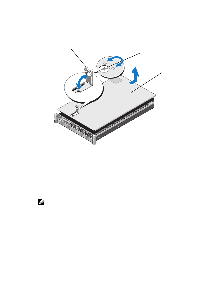
Figure 3-3. Opening and Closing the System
1
2
3
1 latch 2 latch release lock
3 cover
Closing the System
1
Place the cover onto the chassis and offset it slightly toward the back of the
system, so that the slots on the sides of the cover fit into the corresponding
hooks on the sides of the chassis. See Figure 3-3.
NOTE: To close the system properly, ensure that the tabs on the cooling
shroud are seated in the slots on the chassis. See Figure 3-9.
2
Slide the cover toward the front of the chassis till it snaps in position.
3
Push down the latch to secure the cover into the closed position.
4
Rotate the latch release lock in a clockwise direction to secure the cover.
5
Reconnect the system to its electrical outlet and turn the system on,
including any attached peripherals.
Installing System Components 79
Page 80
Hard Drives
All drives connect to the system board through the SAS/SATA backplane
board mounted on the front-chassis assembly. Hard drives are supplied in
hot-swappable drive carriers that fit in the hard-drive bays.
CAUTION: Before attempting to remove or install a drive while the system is
running, see the documentation for the SAS controller card to ensure that the host
adapter is configured correctly to support hot-swap drive removal and installation.
CAUTION: Do not turn off or reboot your system while the drive is being formatted.
Doing so can cause a drive failure.
NOTE: Use only drives that have been tested and approved for use with the
SAS/SATA backplane board.
When you format a hard drive, allow enough time for the formatting to be
completed. Be aware that high-capacity hard drives can take a number of
hours to format.
Removing a Hard-Drive Blank
CAUTION: To maintain proper system cooling, all empty hard-drive bays must
have drive blanks installed.
1
If installed, remove the front bezel
page 77.
2
Grasp the front of the hard-drive blank, press the release button and slide
the blank out until it is free of the drive bay. See Figure 3-4.
. See
"Removing the Front Bezel" on
80 Installing System Components
Page 81
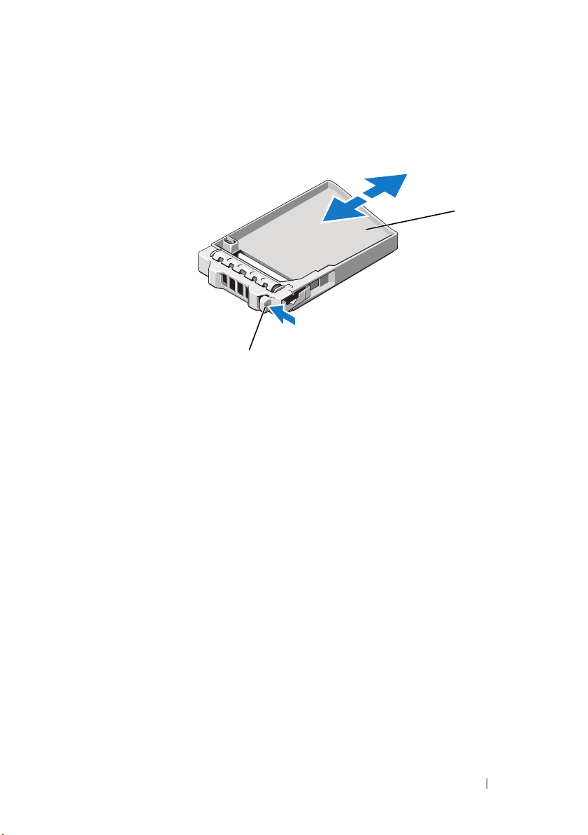
Figure 3-4. Removing and Installing a Hard-Drive Blank
1
2
1 hard-drive blank 2 release button
Installing a Hard-Drive Blank
1
If installed, remove the front bezel
page 77.
2
Insert the drive blank into the drive bay until the release button clicks
into place.
3
If applicable, replace the front bezel. See "Installing the Front Bezel" on
page 77.
. See
"Removing the Front Bezel" on
Installing System Components 81
Page 82

Removing a Hard-Drive Carrier
CAUTION: Ensure that your operating system supports hot-swap drive
installation. See the documentation supplied with the operating system.
1
If installed, remove the front bezel
page 77.
2
From the management software, prepare the drive for removal.
the hard-drive indicators on the drive carrier signal that the drive can be
removed safely.
See your controller documentation for information about
hot-swap drive removal.
If the drive has been online, the green
the drive is powered down. When the drive indicators are off, the drive is
ready for removal.
3 Press the release button on the front of the hard-drive carrier and open
the handle.
The hard-drive carrier handle opens.
4
Slide the hard-drive carrier out until it is free of the drive bay.
CAUTION: To maintain proper system cooling, all empty hard-drive bays must
have drive blanks installed.
5
Insert a drive blank in the empty drive bay. See "Installing a Hard-Drive
Blank" on page 81.
6
If applicable, replace the front bezel. See "Installing the Front Bezel" on
page 77.
. See
"Removing the Front Bezel" on
activity/
fault indicator flashes as
See
Wai t u nt il
Figure 3-5
.
82 Installing System Components
Page 83
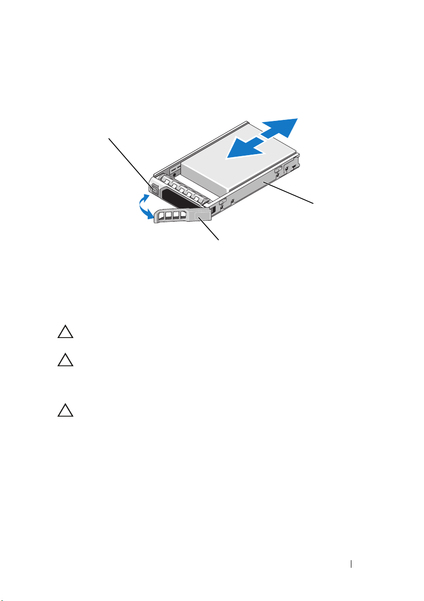
Figure 3-5. Removing and Installing a Hard-Drive Carrier
1
2
3
1 release button 2 hard-drive carrier
3 hard-drive carrier handle
Installing a Hard-Drive Carrier
CAUTION: Use only hard drives that have been tested and approved for use with
the SAS/SATA backplane.
CAUTION: When installing a hard drive, ensure that the adjacent drives are fully
installed. Inserting a hard-drive carrier and attempting to lock its handle next to a
partially installed carrier can damage the partially installed carrier's shield spring
and make it unusable.
CAUTION: Ensure that your operating system supports hot-swap drive
installation. See the documentation supplied with your operating system.
1
If installed, remove the front bezel
page 77.
2
If a drive blank is present in the bay, remove it. See "Removing a HardDrive Blank" on page 80.
3
Press the release button on the front of the hard-drive carrier and open
the handle.
4
Insert the hard-drive carrier into the drive bay until the carrier contacts
the backplane.
5
Close the hard-drive carrier handle to lock the drive in place.
. See
"Removing the Front Bezel" on
Installing System Components 83
Page 84
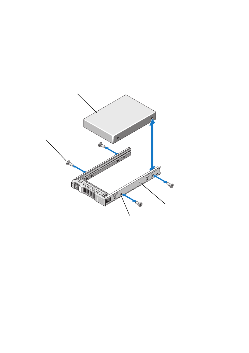
Removing a Hard Drive From a Hard-Drive Carrier
1
2
3
4
Remove the screws from the slide rails on the hard-drive carrier and separate
the hard drive from the carrier. See
Figure 3-6. Removing and Installing a Hot-Swap Hard Drive Into a Hard-Drive Carrier
Figure 3-6
.
1 hard drive 2 hard-drive carrier
3 SAS/SATA screw hole 4 screws (4)
Installing a Hard Drive Into a Hard-Drive Carrier
1 Insert the hard drive into the hard-drive carrier with the connector end
of the drive at the rear. See
2 Align the screw holes on the hard drive with the back set of holes on the
hard-drive carrier.
3 Attach the four screws to secure the hard drive to the hard-drive carrier.
84 Installing System Components
Figure 3-6
.
Page 85

Optical Drive
Your system is provided with an optional slimline SATA DVD-ROM or DVD+/-
RW
optical drive.
NOTE: DVD devices are data only.
Removing an Optical Drive
CAUTION: Many repairs may only be done by a certified service technician.
You should only perform troubleshooting and simple repairs as authorized in
your product documentation, or as directed by the online or telephone service
and support team. Damage due to servicing that is not authorized by Dell is
not covered by your warranty. Read and follow the safety instructions that
came with the product.
1
If installed, remove the front bezel. See "Removing the Front Bezel" on
page 77.
2
Turn off the system, including any attached peripherals, and disconnect
the system from its electrical outlet.
3
Open the system. See "Opening the System" on page 78.
4
Disconnect the power/data cable from the back of the drive.
Note the routing of the power/data cable inside the system as you remove
them from the system board and the drive. Route these cables properly
when you replace them to prevent them from being pinched or crimped.
For more information, see "System Memory" on page 92.
5
To remove the drive, press down and push the blue release tab toward the
front of the system. See Figure 3-7.
6
Slide the optical drive out of the system until it is free of the drive bay.
7
If you are not installing a new optical drive, install the optical drive insert.
8
Close the system. See "Closing the System" on page 79.
9
Reconnect the system to its electrical outlet and turn the system on,
including any attached peripherals.
10
If applicable, replace the front bezel. See "Installing the Front Bezel" on
page 77.
Installing System Components 85
Page 86
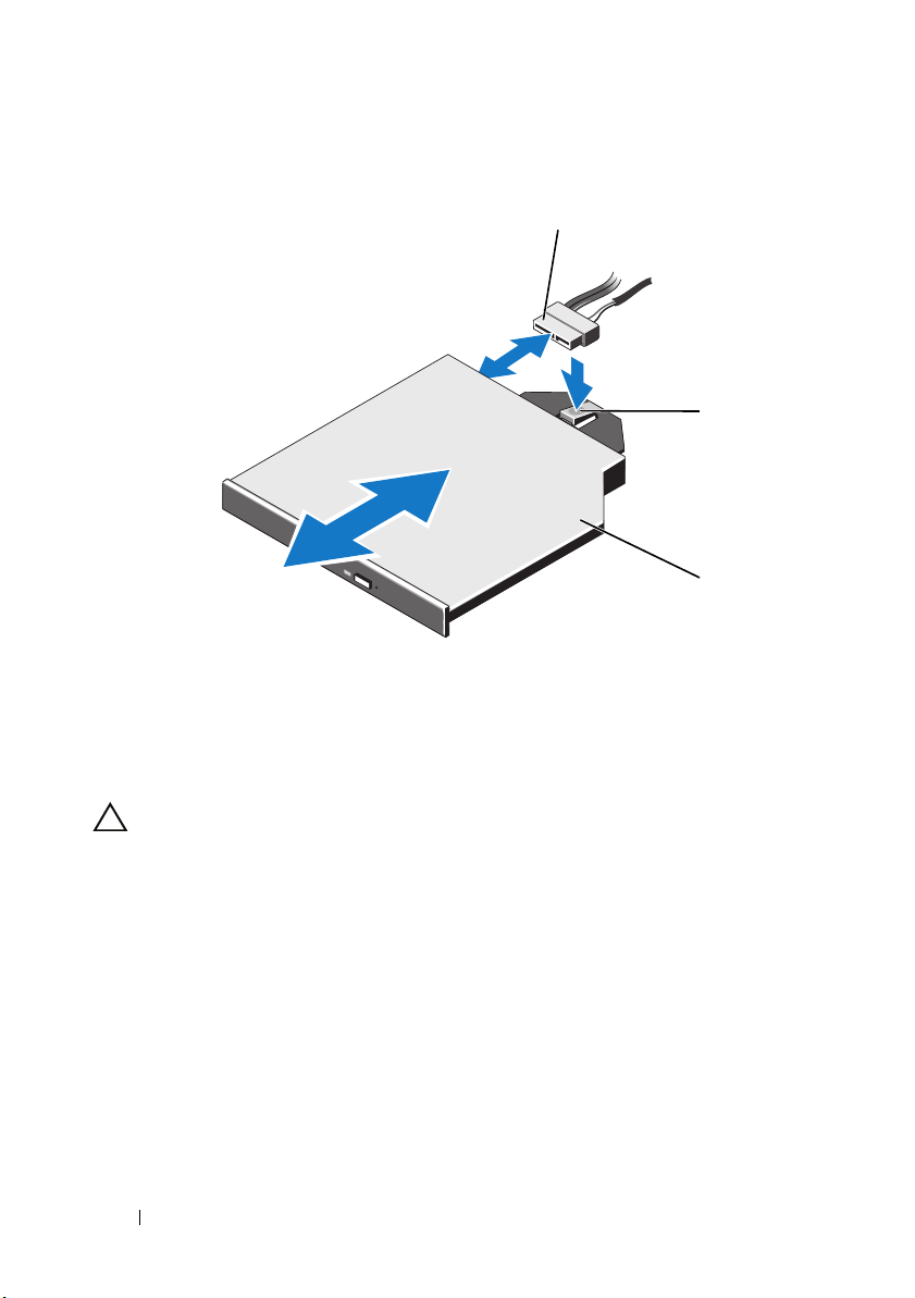
Figure 3-7. Removing and Installing the Optical Drive
1
2
3
1 power/data cable 2 release tab
3 optical drive
Installing an Optical Drive
CAUTION: Many repairs may only be done by a certified service technician.
You should only perform troubleshooting and simple repairs as authorized in
your product documentation, or as directed by the online or telephone service
and support team. Damage due to servicing that is not authorized by Dell is
not covered by your warranty. Read and follow the safety instructions that
came with the product.
1
If installed, remove the front bezel. See "Removing the Front Bezel" on
page 77.
2
Turn off the system, including any attached peripherals, and disconnect
the system from its electrical outlet.
3
Open the system. See "Opening the System" on page 78.
4
Slide the optical drive into the optical drive bay until the blue release tab
snaps into place. See Figure 3-7.
86 Installing System Components
Page 87

5
Connect the power/data cable to the back of the drive and to the
system board.
Route the cable properly inside the system to prevent it from being
pinched or crimped. For more information, see "System Memory" on
page 92.
6
Close the system. See "Closing the System" on page 79.
7
Reconnect the system to its electrical outlet and turn the system on,
including any attached peripherals.
8
If applicable, replace the front bezel. See "Installing the Front Bezel" on
page 77.
Power Supplies
Your system supports two hot-swappable
If two power supplies are installed, the second power supply provides, power
redundancy. In a redundant mode, the system distributes the power load
across both power supplies to maximize efficiency. When a power supply is
removed with the system powered on, the full power load is picked up by the
second power supply. Table 3-1 lists the power supply redundancy modes.
Table 3-1. Power Supply Redundancy Modes
Number of Power Supplies Redundancy Mode System Configuration
1 1+0 Nonredundant
2 1+1 Redundant configuration
1100 W
power supplies.
configuration
Installing System Components 87
Page 88
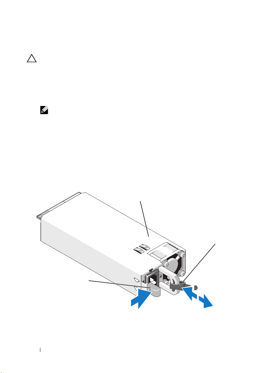
Removing a Power Supply
1
2
3
CAUTION: The system requires one power supply for normal operation. On
power-redundant systems, remove and replace only one power supply at a time in
a system that is powered on.
1
Disconnect the power cable from the power source.
2
Disconnect the power cable from the power supply and remove the Velcro
straps that bundle and secure the system cables.
NOTE: You may have to unlatch and lift the optional cable management arm if
it interferes with power-supply removal. For information about the cable
management arm, see the system’s rack documentation.
3
Press the release latch and pull the power supply out to release it from the
power distribution board and clear the chassis.
If you are permanently removing the power supply, you must install a
power supply blank to ensure proper system cooling. See "Installing the
Power Supply Blank" on page 89.
Figure 3-8. Removing and Installing a Power Supply
1 power supply 2 velcro strap
3 release latch
88 Installing System Components
Page 89
Installing a Power Supply
1
Verify that the power supplies are the same type and have the same
maximum output power.
NOTE: The maximum output power (shown in watts) is listed on the power
supply label.
2
If applicable, remove the power supply blank. See "Removing the Power
Supply Blank" on page 89.
3
Slide the new power supply into the chassis until the power supply is fully
seated and the release latch snaps into place. See Figure 3-8.
NOTE: If you unlatched the cable management arm in step 1 of the previous
procedure, relatch it. For information about the cable management arm, see
the system’s rack documentation.
4
Connect the power cable to the power supply and plug the cable into a
power outlet.
CAUTION: When connecting the power cable, secure the cable with the
Velcro strap.
NOTE: When installing, hot-swapping, or hot-adding a new power supply in a
system, allow several seconds for the system to recognize the power supply and
determine its status. The power-supply status indicator turns green to signify that
the power supply is functioning properly.
Removing the Power Supply Blank
If you are installing a power supply, remove the power supply blank by pulling
outward on the blank.
CAUTION: To ensure proper system cooling, the power supply blank must be
installed in power supply bay PS2 in a non-redundant configuration. Remove the
power supply blank only if you are installing a second power supply.
Installing the Power Supply Blank
NOTE: Install the power supply blank only in power supply bay 2.
To install the power supply blank, align the blank with the power supply bay
and insert the blank into the chassis until it clicks into place.
Installing System Components 89
Page 90

Cooling Shroud
The cooling shroud covers the memory modules and provides air flow to
the system.
Removing the Cooling Shroud
CAUTION: Many repairs may only be done by a certified service technician.
You should only perform troubleshooting and simple repairs as authorized in
your product documentation, or as directed by the online or telephone service
and support team. Damage due to servicing that is not authorized by Dell is
not covered by your warranty. Read and follow the safety instructions that
came with the product.
CAUTION: Never operate your system with the cooling shroud removed. The
system may get overheated quickly, resulting in shutdown and loss of data.
1
Turn off the system, including any attached peripherals, and disconnect
the system from the electrical outlet.
2
Open the system. See "Opening and Closing the System" on page 78.
3
Remove the RAID battery from the battery carrier. See Figure 3-9.
4
Hold the touch points and gently lift the cooling shroud away from the
system. See Figure 3-9.
90 Installing System Components
Page 91
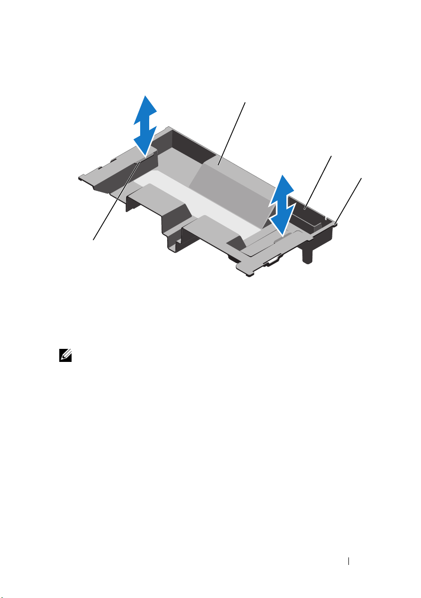
Figure 3-9. Removing and Installing the Cooling Shroud
1
3
2
4
1 cooling shroud 2 RAID battery carrier
3 shroud tabs (6) 4 touch points (2)
Installing the Cooling Shroud
NOTE: For proper alignment of the cooling shroud in the system, ensure that the
cables inside the system are routed along the chassis wall.
1
Lower the cooling shroud into the system and align the cooling shroud
tabs with the slots on the system. See Figure 3-9.
2
Insert the RAID battery into the battery carrier in the cooling shroud. See
"Installing the RAID Battery" on page 117.
3
Close the system. See "Opening and Closing the System" on page 78.
Installing System Components 91
Page 92

System Memory
Your system supports ECC DDR3 registered DIMMs (RDIMMs) and
unbuffered registered DIMMs (UDIMMs). Single-, dual- and quad-rank
DIMMs of speeds up to 1333 MHz (1066 MHz for quad rank) are supported.
RDIMMs of capacities 1 GB, 2 GB, 4 GB, 8 GB, and 16 GB are supported for
a total of up to 256 GB. 1 GB and 2 GB UDIMMs are supported.
The system consists of 16 memory sockets split into two sets of eight sockets;
one set for each processor. Each eight-memory socket set is further organized
into four DDR3 memory channels. The first socket of each DDR3 memory
channel is marked with a white release lever.
Each channel supports up to two single-, dual- or quad-rank RDIMMs or up
to two UDIMMs.
The following features are available with respect to memory:
• Each processor has four DDR3 channels that support speeds up to 1333 MHz.
• UDIMMs and RDIMMs cannot be mixed.
• Your system may support online memory sparing.
• Up to 256 GB of memory (with 16 x 16 GB RDIMMs).
General Memory Module Installation Guidelines
To ensure optimal performance of your system, observe the following general
guidelines when configuring your system memory:
NOTE: Memory configurations that fail to observe these guidelines can prevent
your system from starting and producing any video output.
• DIMMs must be populated in matched set of four or two DIMMs for each
processor (for example, A1/A2, A3/A4). Single DIMM operation is not
supported.
• All processor memory channels must be populated identically
(same speed, size, and type).
• Mixing of memory sizes and ranks is allowed for flexibility.
• The memory configuration for each processor must be identical for
optimal performance.
• Always start memory population at x1, where x is A or B. Sockets A and B
correspond to processors 1 and 2 respectively.
92 Installing System Components
Page 93

• In case of mixed-rank population, first populate the DIMM with the
highest number of ranks (in sockets with white release levers).
• If memory modules with different speeds are installed, they operate at the
speed of the slowest installed memory module(s).
• If online sparing is enabled, identical DIMMs must be installed in the
same slots across each channel.
The system supports advanced ECC, memory interleaving, and online
sparing. For information on memory configurations, see Table 3-2.
Memory Sparing Support
Memory sparing is supported in systems that have one of the fully populated
memory configurations shown in Table 3-2. The memory sparing feature
must be enabled in the Memory Settings screen of the System Setup
program. See "Using the System Setup Program and UEFI Boot Manager" on
page 55.
NOTE: The memory sparing and node interleaving features cannot be used at the
same time. To use memory sparing, you must disable the Node Interleaving option
in the System Setup program.
To support memory sparing, all eight DIMM sockets of each CPU must be
populated. When enabled, memory sparing allocates and reserves one rank of
memory from the installed DIMMs and is large enough to act as spare
memory in the event of a memory rank failure where the contents of the
failed rank is copied to the spared rank.
Installing System Components 93
Page 94
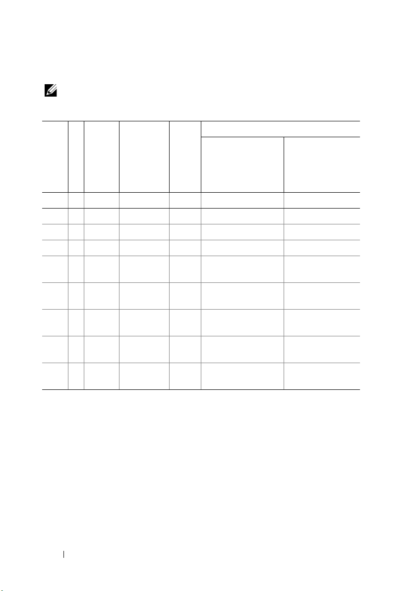
Table 3-2. Memory Configurations
NOTE: DIMMs A1–A8 are assigned to processor 1 and DIMMs B1–B8 are assigned
to processor 2.
Processors
1 2
System Capacity
(in GB)
Number of DIMMs
DIMM Size (in GB)
DIMM Type
Organization
8 8 1 UDIMM x8 A1,A2,A3,A4 B1,B2, B3,B4
8 8 1 RDIMM x8 A1,A2,A3,A4 B1,B2, B3,B4
16 8 2 UDIMM x8 A1,A2,A3,A4 B1,B2, B3,B4
16 8 2 RDIMM x8 A1,A2,A3,A4 B1,B2, B3,B4
32 16 2 UDIMM x8 A1,A2,A3,A4,A5,A6,
A7,A8
32 16 2 RDIMM x8 A1, A2, A3, A4,
A5,A6,A7,A8
64 16 4 RDIMM x4 A1,A2,A3,A4,A5,A6,
A7,A8
a
96
16 8 and 4 RDIMM x4 A1,A2,A3,A4,A5,A6,
A7,A8
128 16 8 RDIMM x4 A1,A2,A3,A4,A5,A6,
A7,A8
a. Eight 8 GB DIMMS are populated in slots A1–A8 and eight 4 GB DIMMS are populated in slots
B1–B8.
B1,B2,B3,B4,B5,B6,
B7,B8
B1,B2,B3,B4,B5,B6,
B7,B8
B1,B2,B3,B4,B5,B6,
B7,B8
B1,B2,B3,B4,B5,B6,
B7,B8
B1,B2,B3,B4,B5,B6,
B7,B8
94 Installing System Components
Page 95
Installing Memory Modules
WARNING: The memory modules are hot to touch for some time after the system
has been powered down. Allow time for the memory modules to cool before
handling them. Handle the memory modules by the card edges. Avoid touching the
components on the memory module and the connectors.
CAUTION: Many repairs may only be done by a certified service technician.
You should only perform troubleshooting and simple repairs as authorized in
your product documentation, or as directed by the online or telephone service
and support team. Damage due to servicing that is not authorized by Dell is
not covered by your warranty. Read and follow the safety instructions that
came with the product.
CAUTION: Handle each memory module only on either card edge, making sure
not to touch the memory module components or connectors.
1
If installed, remove the front bezel
page 77.
2
Turn off the system, including any attached peripherals, and disconnect
the system from the electrical outlet.
3
Open the system. See "Opening the System" on page 78.
4
Remove the cooling shroud. See "Removing the Cooling Shroud" on
page 90.
5
Press down on the ejectors on each end of the socket until the
memory-module blank pops out of the socket. See Figure 3-10.
. See
"Removing the Front Bezel" on
NOTE: Ensure that you retain any removed memory-module blanks for
future use.
Installing System Components 95
Page 96
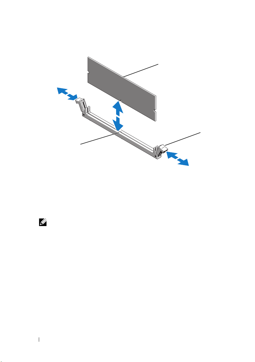
Figure 3-10. Installing and Removing a Memory Module
1
2
3
1 memory module 2 memory module socket ejectors (2)
3 alignment key
6
Align the memory module's edge connector with the alignment key of the
memory module socket, and insert the memory module in the socket.
NOTE: The memory module socket has an alignment key that allows you to
install the memory module in the socket in only one way.
7
Press down on the memory module with your thumbs to lock the memory
module into the socket.
When the memory module is properly seated in the socket, the ejectors on
the memory module socket align with the ejectors on the other sockets
that have memory modules installed.
8
Repeat step 5 through step 7 of this procedure to install the remaining
memory modules. See Table 3-2.
9
Replace the cooling shroud. See "Installing the Cooling Shroud" on
page 91.
10
Close the system. See "Closing the System" on page 79.
96 Installing System Components
Page 97
11
Reconnect the system to its electrical outlet and turn the system on,
including any attached peripherals.
12
If applicable, replace the front bezel. See "Installing the Front Bezel" on
page 77.
13
Power on the system, press <F2> to enter the System Setup program, and
check the
System Memory
setting on the main System Setup screen.
The system should have already changed the value to reflect the newly
installed memory.
14
If the value is incorrect, one or more of the memory modules may not be
installed properly. Repeat step 3 through step 13 of this procedure, checking to
ensure that the memory modules are firmly seated in their sockets.
15
Run the system memory test in the system diagnostics. See "Running the
Embedded System Diagnostics" on page 170.
Removing Memory Modules
WARNING: The memory modules are hot to touch for some time after the system
has been powered down. Allow time for the memory modules to cool before
handling them. Handle the memory modules by the card edges and avoid touching
the components on the memory module.
CAUTION: Many repairs may only be done by a certified service technician.
You should only perform troubleshooting and simple repairs as authorized in
your product documentation, or as directed by the online or telephone service
and support team. Damage due to servicing that is not authorized by Dell is
not covered by your warranty. Read and follow the safety instructions that
came with the product.
CAUTION: To ensure proper system cooling, memory-module blanks must be
installed in any memory socket that is not occupied. Remove memory-module
blanks only if you intend to install memory modules in those sockets.
1
Turn off the system, including any attached peripherals, and disconnect
the system from the electrical outlet.
2
If installed, remove the front bezel. See "Removing the Front Bezel" on
page 77.
3
Open the system. See "Opening the System" on page 78.
CAUTION: Handle each memory module only on either card edge, making sure
not to touch the memory module components or connectors.
Installing System Components 97
Page 98
4
Remove the cooling shroud. See "Removing the Cooling Shroud" on
page 90.
5
Press down and out on the ejectors on each end of the socket until the
memory module pops out of the socket. See Figure 3-10.
6
Lift out the memory module.
NOTE: If you are not replacing the memory module, insert a memory module
blank in the socket.
7
Close the system. See "Closing the System" on page 79.
8
If applicable, replace the front bezel. See "Installing the Front Bezel" on
page 77.
9
Reconnect the system to its electrical outlet and turn the system on,
including any attached peripherals.
Cooling Fans
Your system contains six hot-swappable fans mounted in a fan assembly and
provides cooling for the processors, expansion cards, and memory modules.
NOTE: In the event of a problem with a particular fan, the fan number is referenced
by the system’s management software, allowing you to easily identify and replace
the proper fan by noting the fan numbers on the cooling fan assembly.
Removing a Cooling Fan
WARNING: Opening or removing the system cover when the system is on may
expose you to a risk of electric shock. Exercise utmost care while removing or
installing cooling fans.
WARNING: Allow time for the fan to stop spinning after removing it from the system.
WARNING: Do not attempt to operate the system without the cooling fans.
CAUTION: Many repairs may only be done by a certified service technician.
You should only perform troubleshooting and simple repairs as authorized in
your product documentation, or as directed by the online or telephone service
and support team. Damage due to servicing that is not authorized by Dell is
not covered by your warranty. Read and follow the safety instructions that
came with the product.
NOTE: The procedure for removing each individual fan module is the same.
98 Installing System Components
Page 99
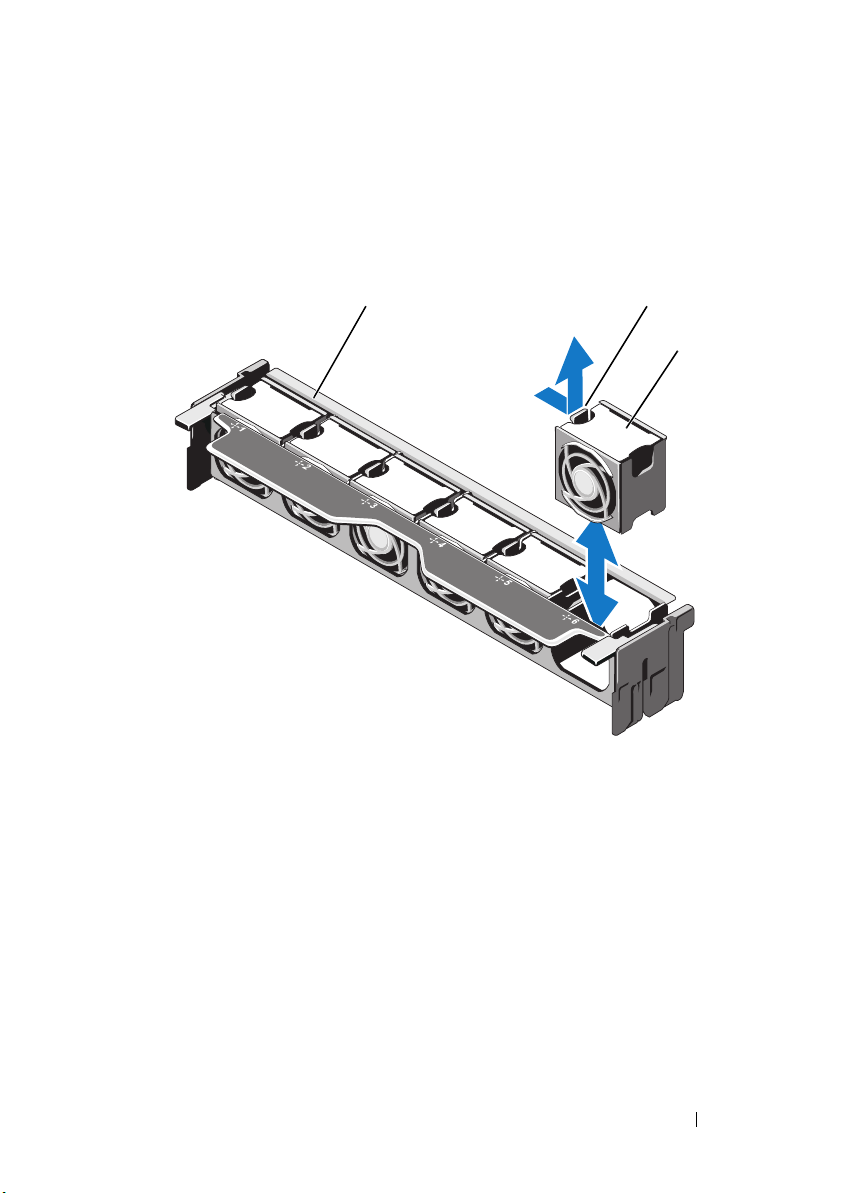
1
1
2
3
2
Open the system. See "Opening the System" on page 78.
2
Press the release tab and lift the fan out of the cooling fan assembly. See
Figure 3-11.
Figure 3-11. Removing and Installing a Cooling Fan
1 fan assembly 2 release tab
3 fan module
Installing System Components 99
Page 100

Installing a Cooling Fan
WARNING: Opening or removing the system cover when the system is on may
expose you to a risk of electric shock. Exercise utmost care while removing or
installing cooling fans.
CAUTION: Many repairs may only be done by a certified service technician.
You should only perform troubleshooting and simple repairs as authorized in
your product documentation, or as directed by the online or telephone service
and support team. Damage due to servicing that is not authorized by Dell is
not covered by your warranty. Read and follow the safety instructions that
came with the product.
1
Align the connector on the fan with the connector on the system board.
See Figure 6-1.
2
Lower the fan into the cooling fan assembly until the release tab snaps into
place. See Figure 3-11.
3
Close the system. See "Closing the System" on page 79.
Removing the Cooling Fan Assembly
CAUTION: Many repairs may only be done by a certified service technician.
You should only perform troubleshooting and simple repairs as authorized in
your product documentation, or as directed by the online or telephone service
and support team. Damage due to servicing that is not authorized by Dell is
not covered by your warranty. Read and follow the safety instructions that
came with the product.
1
Turn off the system, including any attached peripherals, and disconnect
the system from its electrical outlet.
2
Open the system. See "Opening the System" on page 78.
3
Lift the blue release levers to release the cooling fan assembly from the
chassis. See Figure 3-12.
4
Grasp the blue release levers and lift the cooling fan assembly out of the
system. See Figure 3-12.
100 Installing System Components
 Loading...