

Page 1

Dell EMC PowerEdge MX7000 Enclosure
Installation and Service Manual
Regulatory Model: E44S Series
Regulatory Type: E44S001
May 2020
Rev. A06
Page 2

Notes, cautions, and warnings
NOTE: A NOTE indicates important information that helps you make better use of your product.
CAUTION: A CAUTION indicates either potential damage to hardware or loss of data and tells you how to avoid the
problem.
WARNING: A WARNING indicates a potential for property damage, personal injury, or death.
© 2018 2020 Dell Inc. or its subsidiaries. All rights reserved. Dell, EMC, and other trademarks are trademarks of Dell Inc. or its
subsidiaries. Other trademarks may be trademarks of their respective owners.
Page 3

Contents
1 About this document.....................................................................................................................6
2 Next Generation Modular overview................................................................................................ 7
PowerEdge MX architecture overview.............................................................................................................................10
3 Enclosure overview......................................................................................................................11
Front view of the enclosure................................................................................................................................................12
Control panel...................................................................................................................................................................12
PSU indicators................................................................................................................................................................ 15
Fan module indicator codes.......................................................................................................................................... 15
Back view of the enclosure.................................................................................................................................................16
Management module indicator codes..........................................................................................................................17
Locating the information tag of your system................................................................................................................... 17
4 Initial system setup and configuration.......................................................................................... 19
Setting up your enclosure................................................................................................................................................... 19
Management module configuration...................................................................................................................................19
Options to set up the management module IP address............................................................................................19
Log in to the management module..............................................................................................................................20
Methods to download firmware and drivers....................................................................................................................20
Downloading drivers and firmware....................................................................................................................................20
LCD touch panel...................................................................................................................................................................21
LCD features...................................................................................................................................................................21
Assigning an IP address out-of-the-box...........................................................................................................................22
Configuring the Static IP address using the LCD......................................................................................................23
Configuring the DHCP IP address using the LCD..................................................................................................... 23
KVM features.......................................................................................................................................................................24
5 Installing and removing system components.................................................................................26
Safety instructions.............................................................................................................................................................. 26
Before working inside your enclosure...............................................................................................................................26
After working inside your enclosure..................................................................................................................................26
Hot plug and Non-hot plug devices...................................................................................................................................27
Storage and compute sleds................................................................................................................................................27
Removing a sled blank...................................................................................................................................................27
Installing a sled blank..................................................................................................................................................... 28
Removing a compute or storage sled from the enclosure....................................................................................... 29
Installing a compute or storage sled into the enclosure............................................................................................ 31
Cooling fan modules............................................................................................................................................................33
Removing a front fan module.......................................................................................................................................33
Installing a front fan module.........................................................................................................................................33
Removing a rear fan module........................................................................................................................................ 34
Installing a rear fan module...........................................................................................................................................35
Power supply units .............................................................................................................................................................35
Contents 3
Page 4

Removing a power supply unit.....................................................................................................................................35
Installing a power supply unit....................................................................................................................................... 36
Acoustic baffle..................................................................................................................................................................... 37
Removing the air baffle.................................................................................................................................................37
Installing the air baffle................................................................................................................................................... 38
Fabrics and modules............................................................................................................................................................39
Removing a blank from Fabric A or B slot..................................................................................................................39
Installing a blank in Fabric A or B slot..........................................................................................................................39
Removing a module from Fabric A or B slot.............................................................................................................. 40
Installing a module in Fabric A or B slot....................................................................................................................... 41
Removing a MX7000 blank from Fabric C slot..........................................................................................................42
Installing a MX7000 blank in Fabric C slot..................................................................................................................42
Removing a MX7000 module from Fabric C slot...................................................................................................... 43
Installing a MX7000 module into Fabric C slot.......................................................................................................... 44
Removing a management module blank.....................................................................................................................45
Installing a management module blank....................................................................................................................... 46
Removing a management module............................................................................................................................... 47
Installing a management module..................................................................................................................................48
Support information for GPU.............................................................................................................................................49
6 Technical specifications..............................................................................................................50
Component guidelines ....................................................................................................................................................... 50
Population rules............................................................................................................................................................. 50
PSU redundancy and population rules.........................................................................................................................51
Chassis dimensions..............................................................................................................................................................52
Chassis weight.....................................................................................................................................................................52
Fan specifications................................................................................................................................................................53
PSU specifications.............................................................................................................................................................. 53
Ports and connectors specifications.................................................................................................................................53
USB ports....................................................................................................................................................................... 53
Mini DisplayPort.............................................................................................................................................................53
PowerEdge MX modules ports and connectors..............................................................................................................54
PowerEdge MX740c.....................................................................................................................................................54
PowerEdge MX840c.....................................................................................................................................................54
MX7116n Fabric Expander Module.............................................................................................................................. 54
MX9116n Fabric Switching Engine.............................................................................................................................. 54
MX9002m Management Module................................................................................................................................ 55
MX5108n Ethernet Switch...........................................................................................................................................55
MXG610s Fibre Channel Switch..................................................................................................................................55
PowerEdge MX 10GBASE-T Ethernet Pass-Through Module............................................................................... 55
PowerEdge MX 25 Gb Ethernet Pass-Through Module..........................................................................................56
Video specifications............................................................................................................................................................ 56
Environmental specifications............................................................................................................................................. 56
Standard operating temperature................................................................................................................................. 57
Expanded operating temperature................................................................................................................................57
Particulate and gaseous contamination specifications ............................................................................................58
7 Getting help...............................................................................................................................60
Recycling or End-of-Life service information..................................................................................................................60
4
Contents
Page 5

Contacting Dell EMC.......................................................................................................................................................... 60
Documentation feedback....................................................................................................................................................61
Accessing system information by using QRL................................................................................................................... 61
Quick Resource Locator for PowerEdge MX7000 enclosure.................................................................................. 61
Receiving automated support with SupportAssist ......................................................................................................... 61
8 Documentation resources........................................................................................................... 62
Contents 5
Page 6

About this document
This document provides an overview about the PowerEdge MX7000, information about installing and replacing components, technical
specifications, and guidelines to follow while installing components.
1
6 About this document
Page 7
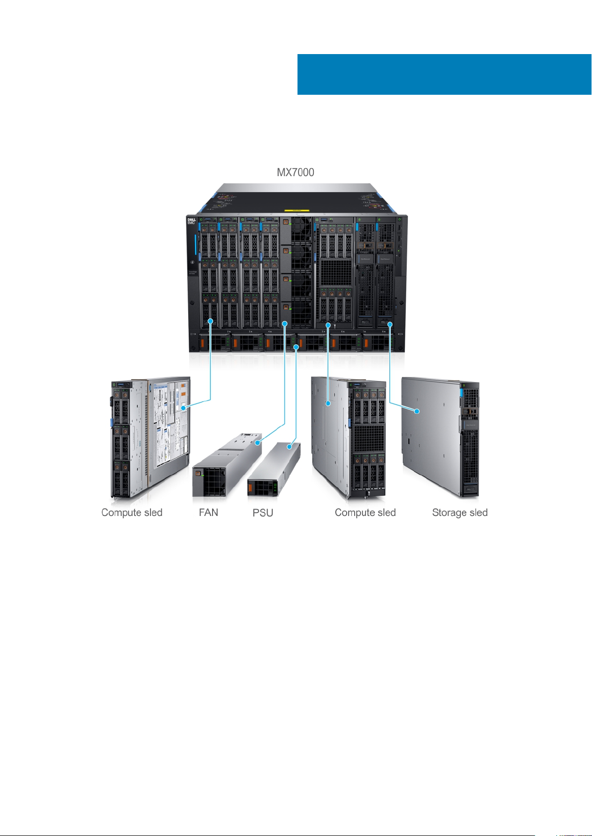
2
Next Generation Modular overview
Figure 1. Next Generation Modular - Front view
• Compute sleds - MX740c, and MX840c
• Storage sled - MX5016s
Next Generation Modular overview 7
Page 8
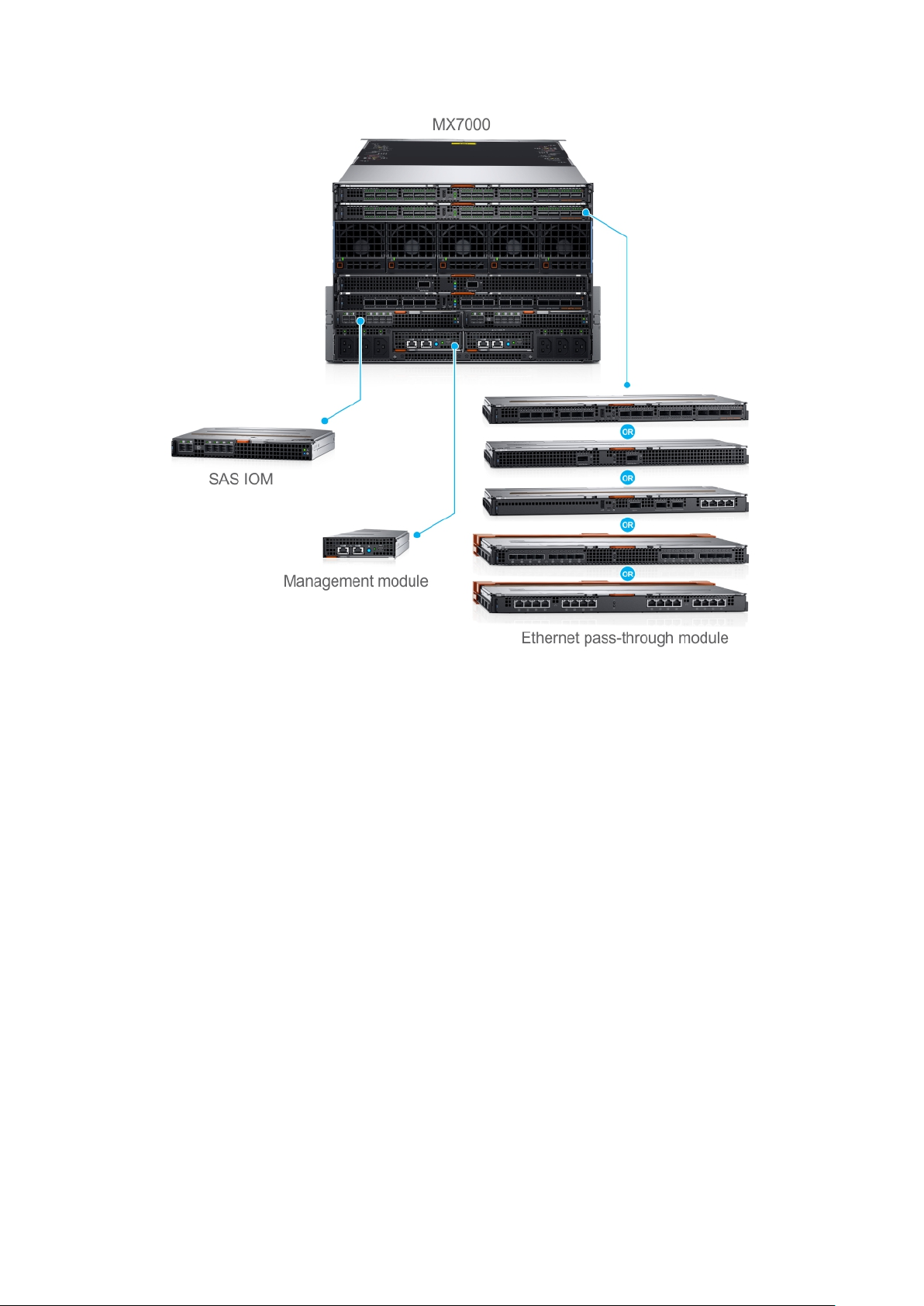
Figure 2. Next Generation Modular - Back view
The Dell EMC PowerEdge MX7000 enclosure supports the following sleds and I/O modules:
• I/O modules -
○ Dell EMC Networking MX7116n Fabric Expander Module
○ Dell EMC Networking MX9116n Fabric Switching Engine
○ Dell EMC Networking MX5108n Ethernet Switch
○ Dell EMC Networking MXG610s Fibre Channel Switch
○ Dell EMC M9002m Management Module
○ Dell EMC PowerEdge MX5000s SAS Switch
• Ethernet Pass-Through Module -
○ Dell EMC PowerEdge MX 10GBASE-T Ethernet Pass-Through Module
○ Dell EMC PowerEdge MX 25 Gb Ethernet Pass-Through Module
• MX740c
The PowerEdge MX740c is a single-width compute sled that supports:
○ Up to two Intel Xeon Scalable Processors
○ Up to 24 DIMM slots
○ Up to six 2.5-inch SAS, SATA, SSD, or NVMe drives
• MX840c
The PowerEdge MX840c is a double-width compute sled that supports:
○ Up to four Intel Xeon Scalable Processors
○ Up to 48 DIMM slots
○ Up to eight 2.5-inch SAS, SATA, SSD, or NVMe drives
• MX5016s
8
Next Generation Modular overview
Page 9

The PowerEdge MX5016s is a single-width storage sled that provides disk expansion for the PowerEdge MX series compute sleds that
support:
○ Up to 16 hot-swappable 2.5-inch SAS drives
○ Two hot-swappable expanders providing dual SAS paths for all drives
○ Dual x4 SAS links to the MX platform infrastructure
○ 12 Gb/s SAS
• Dell EMCManagement Module M9002m
The Dell EMC MX9002m Management Module controls the overall chassis power, cooling, and hosts the OpenManage EnterpriseModular (OME-M) console. Two external 1G-BaseT Ethernet ports are provided to enable management connectivity and to connect
more PowerEdge MX7000 chassis into a single logical chassis. The PowerEdge MX7000 chassis supports two PowerEdge MX9002m
management modules for redundancy. The Management module offers:
• Two x 1G-BaseT Ethernet ports
• One x Micro-B USB port
• Dell EMC Networking MX7116n Fabric Expander Module
The Dell EMC Networking MX7116n Fabric Expander Module operates as an unmanaged Ethernet repeater to connect servers to the
MX9116n Fabric Switching Engine using QSFP28-DD connections. The Expander Module offers:
○ Sixteen 25 GE server-facing ports
○ Two QSFP28-DD ports for connection to a Fabric Switching Engine
• Dell EMC Networking MX9116n Fabric Switching Engine
The Dell EMC Networking MX9116n Fabric Switching Engine is a scalable L2/L3 switch designed that provides high-bandwidth, lowlatency 25 GbE networking. This high-end switch offers:
○ Sixteen 25 GE server-facing ports
○ 12 QSFP28-DD ports that you can use to connect to Fabric Expanders or break out to: 8x10GE or 8x25GE ports for connection to
rack servers or other Ethernet devices, or 2x40GE/2x100GE ports for uplinks, connection to SAN storage, and switch
interconnects
○ Two QSFP28 uplink ports that can operate in 1x100GE, 1x40GE, 4x25GE, 2x50GE, or 4x10GE mode
○ Two QSFP28 unified ports that operate in Ethernet or Fibre Channel 1x100GE, 1x40GE, 4x25GE, 4x10GE, 2x50GE, or
8x8/16/32GFC mode
• Dell EMC Networking MX5108n Ethernet Switch
The Dell EMC Networking MX5108n Ethernet Switch is a basic L2/L3 switch that is designed to provide high-performance, lowlatency networking for the PowerEdge MX7000 installations. It provides FCoE transit, but no native Fibre Channel functionality, and
offers:
○ Eight 25 GE server-facing ports
○ Two 100 GE QSFP28 uplink ports
○ One 40 GE QSFP28 uplink port
○ Four 10GBASE-T uplink ports
• Dell EMC Networking MXG610s Fibre Channel Switch
The Dell EMC Networking MXG610s Fibre Channel Switch provides the following hardware features:
○ Up to 16 external FC ports to connect with external FC storage or an FC switch
○ Up to 16 internal backplane FC ports to connect with the FC controller on the sleds
○ A dual-core T1022E processor operating at 1.2 GHz delivers high performance, scalability, and advanced fabric vision functionality
○ Two 32 Gbps short wavelength (SWL) optical SFP+ transceivers in the entry-level 8-port model
○ Four 32 Gbps SWL optical SFP+ transceivers in the midlevel 16-port model
○ Eight 32 Gbps SWL optical SFP+ transceivers in the enterprise 16-port model
• Dell EMC PowerEdge MX5000s SAS Switch
The Dell EMC PowerEdge MX5000s SAS Switch IOM provides the following hardware features:
○ Up to 8 internal 12Gbit/sec x4 SAS connections
○ Internal SAS Fabric that enables the connectivity without any need for attached cables
• Dell EMC PowerEdge MX 10GBASE-T Ethernet Pass-Through Module
The Dell 10 Gb Ethernet pass-through module II supports 10 Gb connections. It provides a direct connection between the optional
internal Ethernet mezzanine card in the sled and an external Ethernet device. The Ethernet pass-through modules are hot-swappable.
Next Generation Modular overview
9
Page 10

The 10 Gb Ethernet pass-through module enables you to use optical SFP+ (short reach or long reach) and direct- attached copper
(DCA) SFP+ modules.
NOTE: The Ethernet pass-through module does not support 1G mezzanine cards in the sleds.
• Dell EMC PowerEdge MX 25 Gb Ethernet Pass-Through Module
To better address high-performance network and scalability requirements, we are increasingly implementing 25 GbE for their
customers. These implementations capitalize on the 25GbE specification of the 25 Gigabit Ethernet Consortium. The specification
uses a single-lane 25 Gbps Ethernet links and is based on the existing IEEE 100 GbE standard. The 25 GbE is an easier upgrade path
from 10 GbE as it fits into the existing model. It requires half the number of PCIe lanes that are compared to 40 GbE. It leads to better
PCIe bandwidth utilization, and lower power consumption. The 25GbE SFP28 physical interface specification also supports various
form factors, enabling flexible configuration options.
Benefits of deploying 25 GbE:
○ Maximize performance and scalability
○ Lower capital and operating expenses
○ Future upgrade path
For more information about these modules and sleds, see www.dell.com/poweredgemanuals.
Topics:
• PowerEdge MX architecture overview
PowerEdge MX architecture overview
The PowerEdge MX portfolio delivers a fully managed, high-performance system that frees up valuable IT resources and personnel so you
can focus on innovation. It enables you to work beyond silos and routine, daily, and time consuming operational management to realize
your IT and digital business transformations. With the kinetic architecture and Agile management, the MX portfolio dynamically configures
compute, storage, and fabric, increases team effectiveness and accelerates operations. The responsive design delivers the innovation and
longevity customers of all sizes need for their IT and digital business transformations.
The PowerEdge MX infrastructure provides:
Flexible architecture
• A flexible architecture – Nondisruptive provisioning, on-demand allocation of compute, storage, and networking resource pools
• A scalable fabric – Cost-effective multichassis architecture with a broad array of open networking options and upgrade simplicity for
future I/O flexibility
• Granular storage – Dense, highly flexible, hot swappable, scale-out Direct Attached Storage sled with front access bays
Agile management
• End-to-end life cycle management and single point authentication for all devices from a single interface
• Simplified set-up/updates with no specialized training needed, and with multiple at-the-box management options
• An operational template methodology and comprehensive Rest API
Responsive design
• An industry-leading fabric, system thermal architecture, mechanical design, and control algorithms for dense configurations with future
compatibility
• A hardened design to protect, detect, and recover underlying infrastructure from cyber attacks
For more information about these modules and sleds, see their documents which are available at www.dell.com/poweredgemanuals.
10
Next Generation Modular overview
Page 11

3
Enclosure overview
The Dell EMC PowerEdge MX7000 is the next-generation M1000e follow-on chassis and a revolutionary architecture set to be the future
foundation of modular architecture.
The PowerEdge MX7000 enclosure is a 7U chassis that supports:
• Up to eight standard height, single-width sleds, or four standard height, double-width sleds.
Up to seven Storage sleds can be populated in the enclosure.
NOTE: One compute node must be present and it must be mapped to a storage node.
• Up to six hot swappable power supply units.
• Up to two hot swappable management modules.
• Up to six I/O modules:
○ Four Fabric-A/B type IOMs
○ Two Fabric-C type IOMs
• Four front accessible hot swappable cooling fans.
• Five rear accessible hot swappable cooling fans.
For more information about dual management modules, see Technical specifications.
Topics:
• Front view of the enclosure
• Back view of the enclosure
• Locating the information tag of your system
Enclosure overview 11
Page 12
Front view of the enclosure
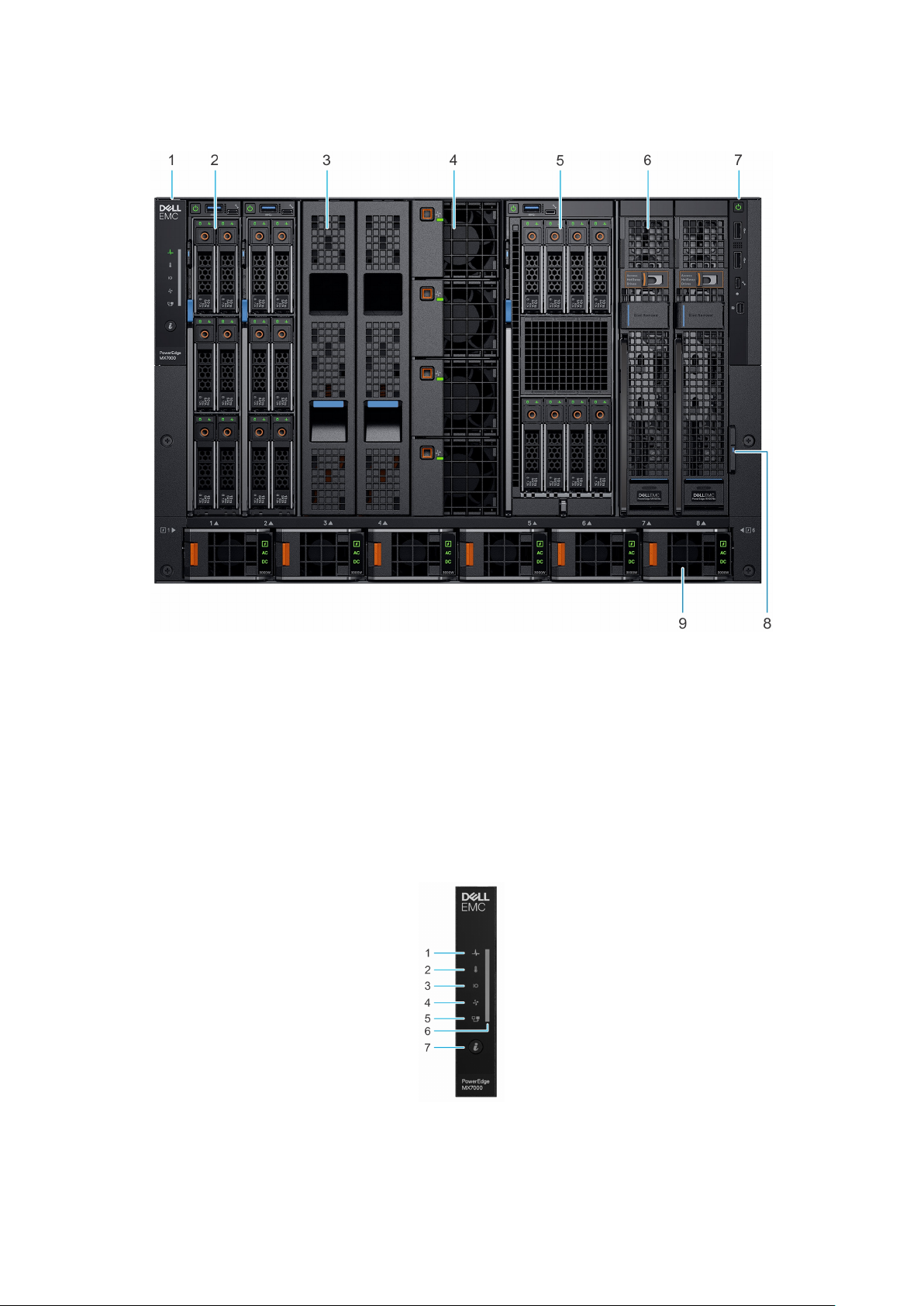
Figure 3. Front view of the enclosure
Left control panel 2. Single-width compute sled
1.
3. Sled blank 4. Front fan (4)
5. Double-width compute sled 6. Single-width storage sled
7. Right control panel 8. Information tag
9. Power supply unit (6)
Control panel
Left control panel
Figure 4. Left control panel - Status LED
12
Enclosure overview
Page 13
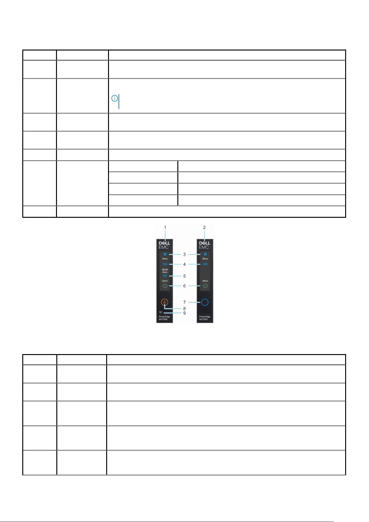
Table 1. Left control panel - LED indicator description
Indicator Description Status
1 System health Blinks amber for 2 seconds and is OFF for 1 second when the chassis health has degraded. By
default, the LED is unlit.
2 System
temperature
3 I/O module health Blinks amber for 2 seconds and is OFF for 1 second when an I/O module is faulty. By default the
4 Fan health Blinks amber for 2 seconds and is OFF for 1 second when a front or rear mounted fan fails or has a
5 Stack or group Indicates that the enclosure is a member of a group.
6 LED status bar Indicator status Description
7 System ID button Allows you to identify the system or the installed sleds.
Blinks amber for 2 seconds and is OFF for 1 second when a thermal fault exists on the enclosure. By
default, the LED is unlit.
NOTE: A thermal fault includes excessive ambient temp, I/O modules thermal status,
PSU thermal status, and fan status.
LED is unlit.
warning. By default, the LED is unlit.
Solid blue Indicates that the enclosure is healthy.
Blinking blue Indicates that the system ID mode is active.
Blinking amber Indicates that the system is experiencing a fault.
Figure 5. Left control panel - LCD options
Table 2. Left control panel - LCD panel description
Indicator Description Status
1 LCD with Quick
Sync
2 LCD without Quick
Sync
3 System ID
indicator on LCD
panel
4 Settings This option button provides access to the inventory and configuration data of the MX7000
5 Optional
QuickSync
indicator (Only for
LCD enabled with Quick Sync module
LCD without Quick Sync module
This option is a button/indicator on the LCD panel to identify the chassis, or choose specific sleds to
identify.
enclosure. It includes the Network Settings, System Information, (Model, Asset Tag, Service Tag),
and Language Settings.
Enables access to QuickSync related controls and connection information.
Enclosure overview 13
Page 14
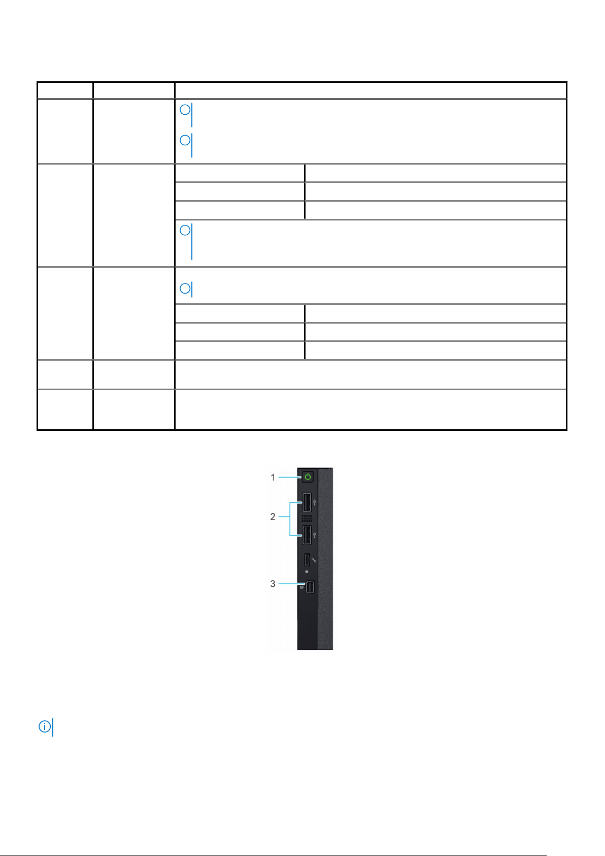
Table 2. Left control panel - LCD panel description(continued)
Indicator Description Status
LCD with
QuickSync 2.0)
6 System alerts
indicator
7
8 Error indicator The error indicator is displayed on the LCD when there are any critical/warning alerts on the
9 Optional Quick
LCD activation
button/
System ID
indicator/
Identification
indicator
Sync wireless
status indicator
NOTE: QuickSync feature allows you to manage your system using mobile devices.
This feature is only available on certain configurations.
NOTE: If not ordered at the time of purchase, the QuickSync module will not be
available on the enclosure.
System ID Indicator status Description
Solid green The chassis has no degraded or critical alerts.
Solid amber The chassis has critical or degraded health alerts.
NOTE: This option button/indicator shows an amber colored alert icon and a combined
critical and degraded alert count. Pressing the button takes the user to the alert
details menu.
Allows you to identify the enclosure.
NOTE: Press the button to activate the LCD.
System ID Indicator status Description
Blinking blue System ID is active.
Blinking amber Chassis alerts are present.
enclosure.
Displays the connection status of the enclosure with any QuickSync enabled device.
Right control panel
Figure 6. Right control panel
1. Power button
2. USB 2.0 port (2)
3. Mini DisplayPort
NOTE: For more information on the ports, see Technical specifications.
14 Enclosure overview
Page 15
PSU indicators
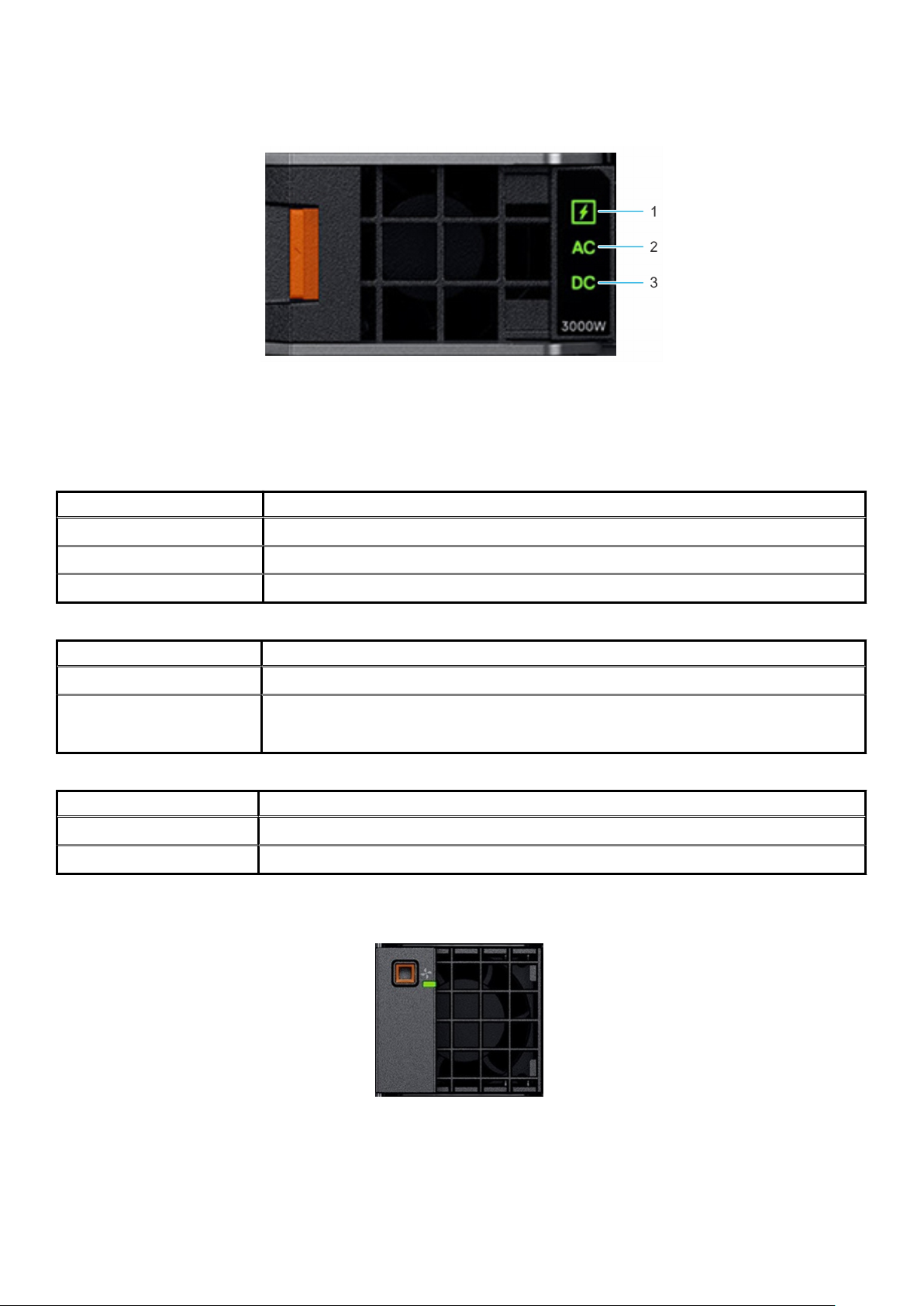
Figure 7. PSU indicators
1. PSU health indicator
2. AC supply status indicator
3. DC output status indicator
Table 3. PSU health indicator codes
PSU health indicator Indicator state
PSU functioning normally Green
PSU faulty Blinking amber
PSU mismatch ON for 1 second, and then 5 blinks and OFF (non-repeating cycle).
Table 4. AC indicator codes
AC indicator Indicator state
AC source available ON
AC source unavailable or
power cable unplugged
OFF
Table 5. DC indicator codes
DC indicator Indicator state
DC output available ON
DC output unavailable OFF
Fan module indicator codes
Figure 8. Front fan module
Enclosure overview
15
Page 16
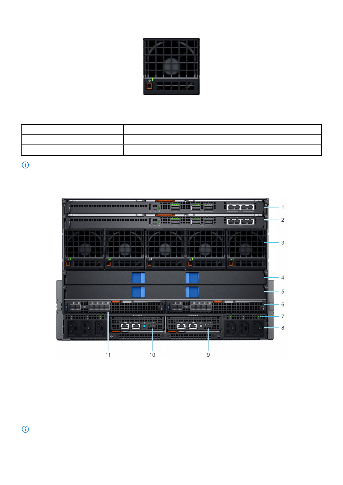
Figure 9. Rear fan module
Table 6. Fan module indicator codes
Fan indicators Indicator state
Fan functioning normally - Front/ Rear Solid green
Fan failure Blinks amber 2 seconds and 1 second OFF
NOTE: When the chassis is powered off with the AC connection that is powered on, only the rear fans are powered off.
Back view of the enclosure
Figure 10. Back view of the enclosure
1.
Slot for Fabric A1 2. Slot for Fabric A2
3. Rear fans (5) 4. Slot for Fabric B1
5. Slot for Fabric B2 6. Slot for Fabric C2
7. Power cable connection status LED 8. C22 Power inlet connectors (6)
9. Management Module 2 10. Management Module 1
11. Slot for Fabric C1
NOTE: For more information about the ports and connectors, see Technical specifications.
16 Enclosure overview
Page 17
Management module indicator codes
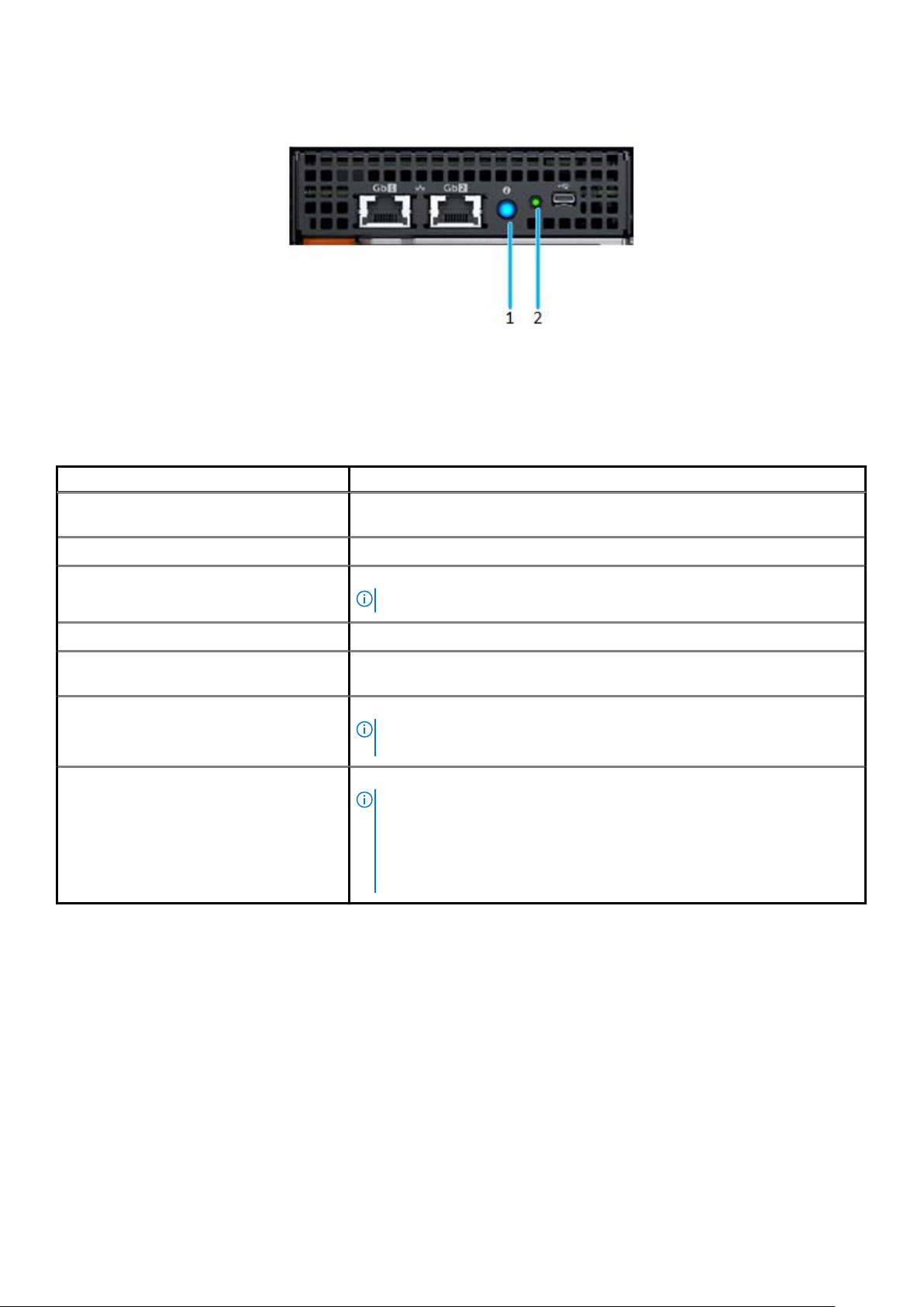
Figure 11. Management module indicators
1. Status indicator, Identification button/ Indicator Dual color: Blue and amber
2. Power indicator - Green
Table 7. Management module indicator behavior
Status Indicator combination
Healthy chassis/ Management module
(Standby)
Healthy chassis/ Management module (Active) Power indicator ON (green), status indicator blue ON
Healthy chassis/ Management module
(Identifying mode)
Faulty chassis/ Management module (Active) Power indicator ON (green), status indicator amber blinking
Faulty chassis/ Management module
(Identifying mode)
Failed chassis/ Management module: Mode 1 Power indicator OFF, status indicator OFF
Failed chassis/ Management module: Mode 2 Power indicator OFF, status indicator Amber-solid
Power indicator ON (green), status indicator OFF
Power indicator ON (green), status indicator blue blinking
NOTE: Available only when the management module is active.
Power indicator ON (green), status indicator blue blinking
NOTE: Hardware failure prevents the management module from
powering.
NOTE:
• The management module starts boot but is unable to boot to one or
more operating system partitions.
• The management module boots but detects a failure such as a network
switch failure, or a voltage regulator failure.
Locating the information tag of your system
You can identify your system using the unique express service code and Service Tag. Pull out the information tag in front of the system to
view the express service code and Service Tag. Alternatively, the information may be on a sticker on the back of the system chassis. The
mini Enterprise Service Tag (EST) is found on the back of the system chassis. Dell uses this information to route support calls to the
appropriate personnel.
Enclosure overview
17
Page 18
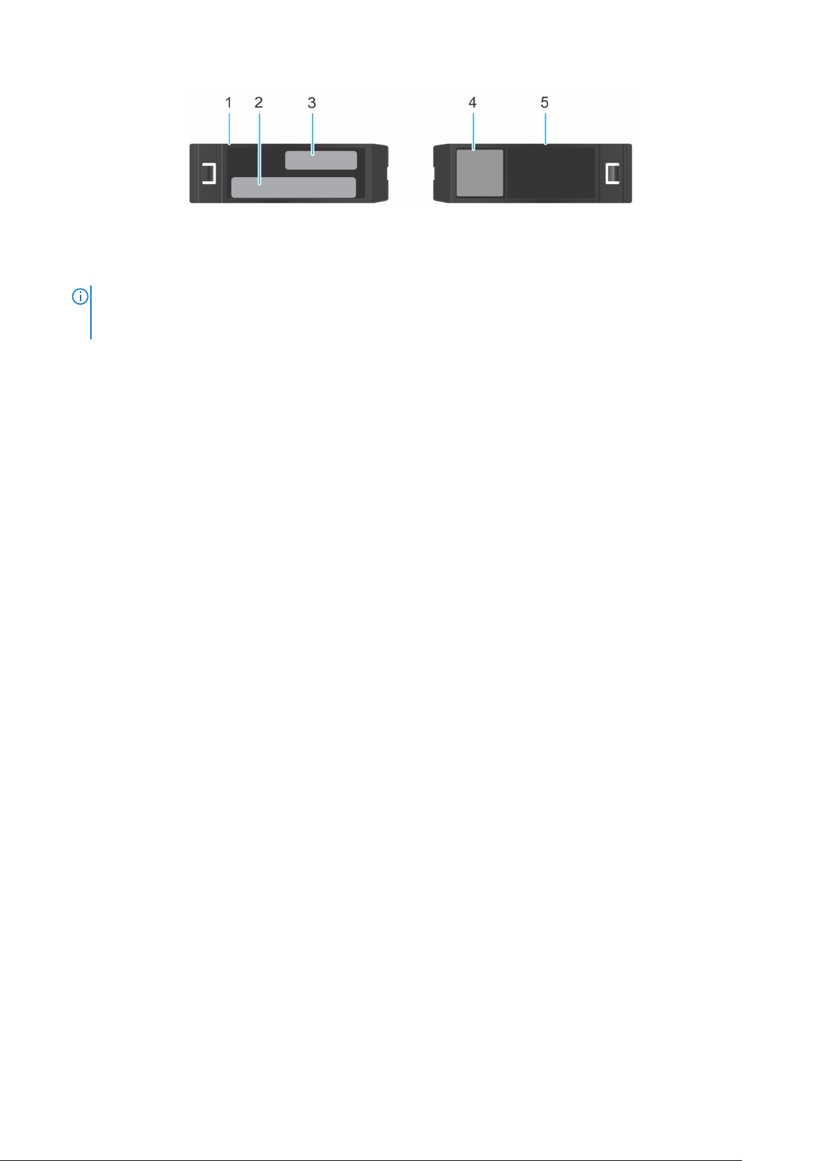
Figure 12. Locating the information tag of your system
1. Information tag (Top view)
2. MAC address and secure password label
NOTE: If you have opted for default access to the management module, the default password is available on the
Information tag. This label is blank, if you have not opted for secure default access, then the default username and
password are root and calvin.
3. Express Service Tag
4. Quick resource locator
5. Information tag (Bottom view)
18 Enclosure overview
Page 19

Initial system setup and configuration
Setting up your enclosure
Complete the following steps to set up your enclosure:
Steps
1. Unpack the enclosure.
2. Install the enclosure into the rack. For more information, see the Rail Installation Guide at www.dell.com/poweredgemanuals.
3. Connect the peripherals to the enclosure.
4. Connect the enclosure to its electrical outlet.
5. Power on the enclosure by pressing the power button.
NOTE: You can configure the static or DHCP IP address using the touch panel on the chassis.
6. Power on the attached peripherals.
For more information about setting up your enclosure, see the Getting Started Guide that shipped with your enclosure.
Management module configuration
4
Using the management module (MM), you can manage SAS storage subsystem, drive assignments, and monitor the health status for the
associated SAS devices. You can manage SAS fabric by using the OpenManage Enterprise-Modular user interface to view inventory,
storage event logs and manage drive or enclosure assignments. For more information about managing the SAS fabric using OpenManage
Enterprise-Modular, see OpenManage Enterprise-Modular User's Guide available at www.dell.com/openmanagemanuals > Chassis
Management Controllers.
Options to set up the management module IP address
Configure the initial network settings on your network infrastructure to enable the communication to and from the management module.
NOTE: For static IP configuration, you must request for it at the time of purchase.
Use the OpenManage Essentials Quick Deploy feature to assign a static or DHCP IP address.
Interfaces
Dell Deployment
Toolkit
Dell Lifecycle
Controller
OpenManage
Enterprise
Modular
Server LCD panel See the LCD touch-panel section.
Management
module and Quick
Sync 2 (optional)
Document/Section
See Dell Deployment Toolkit User’s Guide at www.dell.com/openmanagemanuals > OpenManage Deployment
Toolkit
See Dell Lifecycle Controller User’s Guide at www.dell.com/idracmanuals > Lifecycle Controller
See Dell OpenManage Enterprise-Modular User’s Guide at www.dell.com/openmanagemanuals > Chassis
Management Controllers
See Dell Integrated Dell Remote Access Controller User's Guide at www.dell.com/idracmanuals
NOTE: To access the management module, ensure that all the management modules are connected to the network. You
can also access the management module through the shared LOM mode, if you have opted for a system that has the
shared LOM mode enabled.
Initial system setup and configuration 19
Page 20

Log in to the management module
You can log in to management module as:
• Management module user
• Microsoft Active Directory user
• Lightweight Directory Access Protocol (LDAP) user
If you have opted for secure default access to management module, the management module secure default password is available on the
information tag available on the front of the enclosure. If you have not opted for secure default access to management module, then the
default user name and password are root and calvin. You can also log in by using Single Sign-On or Smart Card.
NOTE: You must have the management module credentials to log in to management module.
NOTE: Ensure that you change the default username and password after setting up the management module IP address.
For more information about logging in to the management module, see the Dell EMC OpenManage Enterprise Modular User's Guide at
www.dell.com/manuals.
Methods of setting up and configuring the IP address for the management module
You can configure management module IP using the following:
1. Management module web interface
2. Remote Access Controller ADMin (RACADM)
3. Remote Services that include Web Services Management (WS-Man)
Methods to download firmware and drivers
You can download the firmware and drivers by using any of the following methods:
Table 8. Firmware and drivers
Methods Location
From the Dell EMC support site www.dell.com/support/home
Using Dell Repository Manager (DRM) www.dell.com/openmanagemanuals > Repository Manager
Using Dell OpenManage Essentials www.dell.com/openmanagemanuals > OpenManage Essentials
Using Dell OpenManage Enterprise www.dell.com/openmanagemanuals > OpenManage Enterprise
Using Dell Server Update Utility (SUU) www.dell.com/openmanagemanuals > Server Update Utility
Using OpenManage Enterprise Modular www.dell.com/openmanagemanuals > OpenManage Enterprise
Modular
Downloading drivers and firmware
Dell EMC recommends that you download and install the latest BIOS, drivers, and systems management firmware on your system.
Prerequisites
Ensure that you clear the web browser cache before downloading the drivers and firmware.
Steps
1. Go to www.dell.com/support/home.
2. In the Drivers & Downloads section, type the Service Tag of your system in the Enter a Service Tag or product ID box, and then
click Submit.
20
Initial system setup and configuration
Page 21

NOTE: If you do not have the Service Tag, select Detect Product to allow the system to automatically detect the
Service Tag, or click View products, and navigate to your product.
3. Click Drivers & Downloads.
The drivers that are applicable to your system are displayed.
4. Download the drivers to a USB drive, CD, or DVD.
LCD touch panel
The LCD touch panel (optional) is on the left control panel of your enclosure.
The LCD touch panel displays the following options:
• System information
• System status
• Error messages
• QuickSync options - Available on the optional QuickSync LCD panel only.
NOTE: The LCD touch panel is not a hot swappable module. Before you replace the module, power off the enclosure and
disconnect the AC power from the chassis.
The LCD touch panel enables you to scroll or swipe on the screen. The options available on the LCD touch panel are:
• Welcome Screen - Enables you to select your native language and the default LCD home page.
• Main Menu - Enables you to access the LCD functionality such as Identify, Settings, QuickSync, Alerts, Help, and Powered off.
• QuickSync - Enables you to connect OpenManage Mobile to the enclosure.
• Alerts - Enables you to view a list of all the critical and warning alerts of the enclosure.
• Network Settings - View and configure the chassis management IP address.
• LCD Configuration - Enables you to configure the LCD options such as View and Modify, View only, Disabled, Present, and Not
present.
• Settings - Enables you to edit the Network settings, LCD Language, and Home screen.
• Service Interaction - Displays the impact on drive mapping when a server or sled is replaced in the enclosure.
• System Info - Displays the Model number, Asset tag, and Service tag of the enclosure.
• Chassis Power Off - Enables you to perform a Shutdown or Graceful shutdown.
LCD features
Multi-Chassis Management group
About this task
The PowerEdge MX7000 enclosures LCD allows you to manage the enclosures Multi-Chassis Management (MCM) group. In this
management feature, a lead enclosure will manage a subset of enclosures.
The MCM groups management feature allows you to perform the actions mentioned below:
• Viewing the group status
• Creating a group
• Joining a group
• Leaving a group
• Deleting a group
Viewing the group status
To view a group status
Steps
1. From the selected home screen, tap Settings.
2. Tap Manage Group.
Initial system setup and configuration
21
Page 22

Creating a group
To create a stand-alone chassis group
Steps
1. From the selected home screen, tap Settings.
2. Tap Manage Group.
3. To create a group, tap Select Group.
NOTE: A confirmation message is displayed.
NOTE: It may take several minutes to update the available group names.
Joining a group
To join a stand-alone chassis group
Steps
1. From the selected home screen, tap Settings.
2. Tap Manage Group.
3. To join a group, tap Join Group.
NOTE: If no available groups, an error message is displayed.
NOTE: If there are available groups, a list of available group names is displayed.
Leaving a group
To leave a member chassis group
Steps
1. From the selected home screen, tap Settings.
2. Tap Manage Group.
3. To exit a group, tap Leave Group.
NOTE: A confirmation message is displayed.
Deleting a group
To delete a lead chassis group
Steps
1. From the selected home screen, tap Settings.
2. Tap Manage Group.
3. To exit a group, tap Leave Group.
NOTE: A confirmation message is displayed.
Assigning an IP address out-of-the-box
About this task
The PowerEdge MX7000 enclosure offers out-of-the-box IP address assignment using the LCD touch panel. For more information about
the LCD, see LCD touch panel.
22
Initial system setup and configuration
Page 23

Steps
1. To set up the IP address out-of-the-box:
1. Select the Language, and tap Next.
The select Home Page screen is displayed.
2. Tap Preview, to view the default Home page view.
The available Home page views are:
• Main Menu
• IP Settings
• System Info
• Custom Text String
The Home Page Preview screen is displayed.
3. Tap Save to store the settings.
NOTE: You can tap Home Pages to view the selected Home Page screen.
Configuring the Static IP address using the LCD
Steps
1. The PowerEdge MX7000 enclosures LCD touch panel enables you to configure the Static or the DHCP IP address.
To configure the Static IP address:
1. From the selected home screen, tap Settings.
2. Tap Network Settings.
3. Select IPv4, and tap Edit.
The Change IP settings from DHCP to Static? screen is displayed.
4. Tap Yes.
5. Update the IPv4 octet, and tap Next.
6. Edit the Mask octet, and tap Next.
7. Edit the Gateway octet, and tap Save.
The Success screen is displayed.
NOTE: If the IP address is incorrect, an Error screen is displayed.
Configuring the DHCP IP address using the LCD
Steps
1. To configure the DHCP IP address:
1. From the selected home screen, tap Settings.
2. Tap Network Settings.
3. Select IPv6 and, tap Edit.
The Change IP settings from DHCP to Static? screen is displayed.
4. Tap Yes.
5. The network IP address is automatically updated in the enclosure.
The Success screen is displayed.
NOTE: If the IP address is incorrect an Error screen is displayed.
Initial system setup and configuration 23
Page 24

KVM features
The PowerEdge MX7000 supports Keyboard, Video, Mouse (KVM) which provides access to the servers via the management modules.
KVM functionality
The keyboard, video, mouse (KVM) solution from Dell includes an LED screen, a keyboard, and a touch pad mouse, all contained in a
space-saving 1U package. The KVM provides access to the servers via the management modules. The management module receives the
keyboard/mouse events and redirects the input to the virtual USB keyboard/mouse to the compute sled iDRAC. The management module
automatically redirects the chassis console output to the front panel display port.
The KVM accessibility keys are:
• Open the OSD menu - Press the PrintScreen key twice to enable the On Screen Display (OSD).
• Navigation - Use the Up or Down arrow keys to scroll through the list of available sled.
• Access a sled - Press the Enter key to select a sled.
• Exit a sled - Press the Escape key to exit the OSD/sled selection menu.
KVM supported ports
The KVM solution supported ports for the PowerEdge MX7000 enclosure are:
• Mini display port
• Mini display port to VGA adapters
• Mini display port to display port cables
Out of the box IP setup using the KVM
To setup the IP address out of the box using the KVM:
1. Connect the keyboard and mouse to the USB ports on the right control panel.
2. Connect the display port or the display port adapter to the display port on the right control panel.
The KVM selection menu is displayed.
3. Select OME Modular from the list.
The OME credentials page is displayed.
4. Enter the login credentials and login to the OME user interface.
The RACADM CLI screen is displayed.
KVM supported RACADM commands
Table 9. KVM supported RACADM commands
Command Description
help
help <subcommand>
?
? <subcommand>
arp
Displays a list of RACADM subcommands.
Displays the usage summary for a subcommand.
Displays a list of RACADM subcommands.
Displays the usage summary for a subcommand.
Displays the networking ARP table.
getmodinfo
chassisaction
chassislog
cmcchangeover
connect
24 Initial system setup and configuration
Displays the module configuration and status information.
Performs a chassis power on/off or power cycle/reset operation.
Displays the chassis log messages.
Toggles the redundant state of the CMC between active/standby.
Connects the switch or blade serial console.
Page 25

Table 9. KVM supported RACADM commands(continued)
Command Description
debug
Enables the debug authorization commands.
deploy
faultlist
getniccfg
getsensorinfo
getsysinfo
getpminfo
getpbinfo
racreset
racresetcfg
swinventory
serveraction
setniccfg
traceroute
traceroute6
ifconfig
ping
Deploys the blade or IOM with specified properties.
Displays the active messages in the chassis subsystem.
Displays the current network settings.
Displays the system sensor information.
Displays the general management module and system information.
Displays the power management status information.
Displays the power budget status information.
Performs a management module reset operation.
Performs a management module factory reset operation.
Displays the list of software's installed on the chassis.
Perform a server or storage power management operation.
Modify the network configuration properties.
Displays the route packets trace to network host.
Displays the IPv6 route packets trace to network host.
Displays the network interface information.
Sends ICMP echo packets on the network.
ping6
getconfig
config
chassisgroup
Sends IPv4 ICMP echo packets on the network.
Displays the management module configuration properties.
Modify the management module configuration properties.
Enables multiple chassis management.
KVM limitations
The KVM features are disabled in the following scenarios:
• If the iDRAC is undergoing a reset process.
• If the management module is undergoing a reset process or not active.
• The OSD is blank until the management module is active.
• DP - DVI and DP - HDMI are not supported by the PowerEdge MX7000 KVM solution.
• The maximum resolution that is supported by the PowerEdge MX7000 are:
○ 1920 x 1200, 32 bits per pixel @ 60 Hz
○ 1600 x 1200, 32 bits per pixel @ 75 Hz
For more information about the PowerEdge MX7000 at the box serial access feature of the chassis management firmware , see
PowerEdge MX7000 At-the-Box Serial Access to Management Firmware
For more information about the PowerEdge MX7000 supported RACADM Commands, see Dell EMC OpenManage Enterprise Modular
Edition Version 1.00.01 for PowerEdge MX7000 Chassis
Initial system setup and configuration
25
Page 26

Installing and removing system components
Safety instructions
WARNING: To avoid injury, do not attempt to lift the enclosure by yourself. Dell recommends that a minimum of two
people lift the enclosure.
WARNING: Opening or removing the cover while the enclosure is powered on may expose you to a risk of electric shock.
CAUTION: Many repairs may only be done by a certified service technician. You should only perform troubleshooting and
simple repairs as authorized in your product documentation, or as directed by the online or telephone service and
support team. Damage due to servicing that is not authorized by Dell is not covered by your warranty. Read and follow
the safety instructions that are shipped with your product.
NOTE: Dell recommends ESD protection while working on components inside the enclosure.
CAUTION: For proper operation and cooling for all the sleds, module bays, power supply units, and system fans must be
populated with a component or a blank.
5
Before working inside your enclosure
Prerequisites
Follow the safety guidelines listed in Safety instructions.
Steps
1. Power off the compute sleds, the storage sleds, and then the attached peripherals.
2. Disconnect the sleds, and the peripherals from the enclosure.
3. Power off the enclosure.
4. Disconnect the enclosure from the electrical outlet.
5. Remove the enclosure from the rack.
For more information, see the Rack Installation Guide at www.dell.com/poweredgemanuals.
After working inside your enclosure
Prerequisites
Follow the safety guidelines listed in Safety instructions.
Steps
1. Install the enclosure into the rack, if removed.
For more information, see the Rack Installation Guide at www.dell.com/poweredgemanuals.
2. Connect the enclosure to the electrical outlet.
3. Power on the enclosure.
4. Reconnect the sleds, and the peripherals into the enclosure.
5. Power on the attached peripherals, the storage sleds, and then the compute sleds.
26 Installing and removing system components
Page 27

Hot plug and Non-hot plug devices
Table 10. Hot plug devices
Hot plug devices Non-hot plug devices
Cooling fans Main distribution board
Power supply units Vertical power distribution board
Management services modules Rear fan board
Fabric A/ B/ C input output modules Left and right control panels
Sleds
NOTE: Ensure that the sled is powered off before
removing it from the enclosure.
Storage and compute sleds
Removing a sled blank
Prerequisites
1. Follow the safety guidelines listed in Safety instructions.
Steps
1. Press the release button to release the sled blank.
2. Pull the sled blank out of the enclosure.
CAUTION:
overheating.
Ensure to install a sled blank in all the empty bays. Operating the enclosure without a blank results in
Installing and removing system components 27
Page 28

Figure 13. Removing a sled blank
Next steps
1. Install a sled or sled blank.
Installing a sled blank
Prerequisites
1. Follow the safety guidelines listed in Safety instructions.
Steps
1. Align the sled blank with the bay in the enclosure.
2. Insert and push the sled blank, until it locks into place.
NOTE: Install two sled blanks when a double-width sled is removed.
28 Installing and removing system components
Page 29

Figure 14. Installing a sled blank
Removing a compute or storage sled from the enclosure
Prerequisites
1. Follow the safety guidelines listed in Safety instructions.
2. Power off the sled.
CAUTION: Ensure the compute sleds mapped to the storage sleds are powered off.
CAUTION: Remove the storage sled only when the hard drive LED is off.
NOTE: If the storage sled drive LED indicator is off, it indicates that all the compute sleds mapped to the storage
sled are powered off.
NOTE: If there are two Fabric C SAS IOMs in powered on state, the management module in the enclosure powers on
the storage sleds automatically.
Steps
1. To remove a storage or compute sled:
NOTE: The procedure to remove a single-width and double-width compute sled is the same.
For a storage sled,
a. Open the sled removal hatch on the front panel of the sled.
b. To release the sled release lever, push the blue release button to the unlock position.
For a compute sled,
a. To release the sled release lever, push the blue release button on the sled.
2. Hold the sled release lever, pull the sled out of the enclosure.
NOTE: Ensure that you install a sled blank if you are removing the sled permanently.
Installing and removing system components 29
Page 30

CAUTION: Operating the enclosure without a blank, for an extended time can result in overheating.
CAUTION: Ensure that the sled is supported with both hands while you are removing the sled.
Figure 15. Removing a storage sled from an enclosure
Figure 16. Removing a single-width compute sled from the enclosure
3. Install the I/O connector cover on the sled.
30
Installing and removing system components
Page 31

Next steps
1. Install a sled or a sled blank.
Installing a compute or storage sled into the enclosure
Prerequisites
1. Follow the safety guidelines listed in Safety instructions.
2. Ensure that the sled release lever is in the open position.
Steps
1. Remove the I/O connector cover from the sled.
Figure 17. Removing the I/O cover
2. Hold and align the sled with the bay in the enclosure.
3. Push the sled into the bay in the enclosure.
NOTE: The procedure to install a single-width and double-width sled is the same.
4. Close the release lever to lock the sled in place.
Installing and removing system components
31
Page 32

Figure 18. Installing a single-width compute sled into the enclosure
Figure 19. Installing a storage sled into the enclosure
Next steps
1. Power on the sled.
32
Installing and removing system components
Page 33

Cooling fan modules
NOTE: The system must be populated with the full set of fans to support the airflow requirements of the chassis.
Removing a front fan module
Steps
1. Press the release button to release the fan module.
2. Hold and pull the fan module out of the fan bay.
Figure 20. Removing a front fan module
Next steps
1. Install a front fan module.
Installing a front fan module
Steps
1. Insert the fan module into the fan bay.
2. Push the fan module into the fan bay, until it locks into place.
Ensure that the green LED on the fan module is illuminated, indicating that the module is functioning
NOTE:
properly.
Installing and removing system components 33
Page 34

Figure 21. Installing the front fan module
Removing a rear fan module
Steps
1. Press the release button to release the fan module.
2. Hold and pull the fan module out of the fan bay.
Figure 22. Removing a rear fan module
34
Installing and removing system components
Page 35

Next steps
1. Install the rear fan module.
Installing a rear fan module
Steps
1. Insert the fan module into the fan bay.
2. Push the fan module into the fan bay, until it locks into place.
NOTE: Ensure that the green LED on the fan module is illuminated, indicating that the module is functioning
properly.
Figure 23. Installing a rear fan module
Power supply units
Removing a power supply unit
Prerequisites
CAUTION: At least two power supply units (PSUs) must be installed for the enclosure to function properly.
1. Follow the safety guidelines listed in Safety instructions.
2. Disconnect the power cable from the power connector associated to the PSU you intend to remove.
Steps
1. Press the orange release button to open the PSU release lever.
2. Hold the release lever, pull the PSU out of the enclosure.
CAUTION: Ensure that you install a PSU blank if you are removing a PSU permanently.
Installing and removing system components 35
Page 36

Figure 24. Removing a power supply unit
Next steps
1. Install a PSU or a PSU blank.
Installing a power supply unit
Prerequisites
1. Follow the safety guidelines listed in Safety instructions.
Steps
1. Push the PSU into the enclosure until it is seated firmly.
2. Close the PSU release lever to secure the PSU in the bay.
36
Installing and removing system components
Page 37

Figure 25. Installing a power supply unit
Next steps
1. Connect the power cable to the corresponding PSU connector on the rear of the chassis.
NOTE:
When installing or hot swapping a PSU, wait for 15 seconds for the system to recognize the PSU and
determine its status. The PSU redundancy may not occur until discovery is complete. Wait until the new PSU is
discovered and enabled before you remove any PSU. The PSU status indicator turns green to indicate that the PSU
is functioning properly.
Acoustic baffle
NOTE: Ensure to install the air baffle to reduce the noise level of the enclosure.
Removing the air baffle
Steps
1. Press the release latch to detach the air baffle from the enclosure.
2. Pull the air baffle to remove it from the enclosure.
Installing and removing system components
37
Page 38

Figure 26. Removing the air baffle
Installing the air baffle
Steps
1. Align the air baffle with the enclosure.
2. Push the air baffle, until it locks into place.
Figure 27. Installing the air baffle
38
Installing and removing system components
Page 39

Fabrics and modules
There are several connections on the Main Distribution Board to enable communication between the IOMs. Between each pair of IOMs
(C1 and C2), there is a link for intermodule communication. This link is referred as Fabric-V in the schematics. This link supports a x1
connection with each lane operating up to 10 Gbps per direction. In addition to the Fabric-V, there are handshake signals between the two
modules to facilitate redundancy/failover or other module to module communication. The usage of these interconnects depends on the
IOM design and its particular requirements.
There are three fabrics connections available in MX7000 enclosure.
• General purpose (2) - Fabric A and B
• Storage (1) - Fabric C
• Fabric module A or B
• Fabric module C
• Management module
Removing a blank from Fabric A or B slot
Steps
1. Press the blue release button to release the blank.
2. Pull the blank out of the enclosure.
NOTE: To maintain proper airflow, ensure that the blanks are installed if the IOMs are not installed.
Figure 28. Removing a blank from Fabric A or B slot
Next steps
1. Install a module in the Fabric A or B slot or a blank.
Installing a blank in Fabric A or B slot
Prerequisites
1. Follow the safety guidelines listed in Safety instructions.
Installing and removing system components
39
Page 40

2. Remove the module from Fabric A or B slot.
Steps
1. Align and insert the blank in the empty slot.
2. Push the blank, until it locks into place.
Figure 29. Installing a blank in Fabric A or B slot
Removing a module from Fabric A or B slot
Prerequisites
1. Follow the safety guidelines listed in Safety instructions.
2. Disconnect the cables that are connected to the modules.
Steps
1. Press the orange release button on the module to open the release levers.
2. Hold the release levers, and pull the module out of the enclosure.
NOTE: Ensure that you install an IOM blank if you are removing a module permanently.
40 Installing and removing system components
Page 41

Figure 30. Removing a module from Fabric A or B slot
Next steps
1. Install a module into Fabric A or B slot or a blank.
Installing a module in Fabric A or B slot
Prerequisites
1. Follow the safety guidelines listed in Safety instructions.
Steps
1. Align and push the I/O module into the enclosure.
2. Close the release lever to lock the module in place.
Figure 31. Installing a module into Fabric A or B slot
Installing and removing system components
41
Page 42

Next steps
1. Connect the cables to the module.
Removing a MX7000 blank from Fabric C slot
Steps
1. Press the release button to release the blank.
2. Pull the blank out of the enclosure.
NOTE: To maintain proper airflow, ensure that the blanks are installed if the MX7000 IOMs is not installed.
Figure 32. Removing a blank from Fabric C slot
Next steps
1. Install the module in the Fabric C slot or a blank.
Installing a MX7000 blank in Fabric C slot
Prerequisites
1. Follow the safety guidelines listed in Safety instructions.
2. Remove the module from Fabric C slot.
Steps
1. Align and insert the blank in the empty slot.
2. Push the blank until it locks into place.
42
Installing and removing system components
Page 43

Figure 33. Installing a blank in Fabric C slot
Removing a MX7000 module from Fabric C slot
Prerequisites
1. Follow the safety guidelines listed in Safety instructions.
2. Disconnect the cables that are connected to the modules.
Steps
1. Press the orange release button on the module to open the release lever.
2. Hold the release lever, and pull the I/O module out of the enclosure.
NOTE: Ensure that you install MX7000 an IOM blank if you are removing a module permanently.
Installing and removing system components 43
Page 44

Figure 34. Removing a MX7000 module from Fabric C slot
Next steps
1. Install a module into Fabric C or Install a blank.
2. Connect the cables to the module.
Installing a MX7000 module into Fabric C slot
Prerequisites
1. Follow the safety guidelines listed in Safety instructions.
Steps
1. Align and push the I/O module into the enclosure.
2. Close the release lever to lock the module in place.
44
Installing and removing system components
Page 45

Figure 35. Installing a MX7000 module into Fabric C slot
Next steps
1. Connect the cables to the module.
NOTE:
Ensure that the SAS IOMs have the same firmware version. The OpenManage-Enterprise modular User interface
allows you to view the firmware details. For more information, see
OpenManage Enterprise-Modular User's Guide
Removing a management module blank
Steps
1. Press the release button to release the blank.
2. Pull the blank out of the enclosure.
NOTE: To maintain proper airflow, ensure that the blanks are installed if the management module is not installed.
.
Installing and removing system components 45
Page 46

Figure 36. Removing a management module blank
Next steps
1. Install the management module or Install a blank.
Installing a management module blank
Prerequisites
1. Follow the safety guidelines listed in Safety instructions.
2. Remove the management module.
Steps
1. Align and insert the blank in the empty slot.
2. Insert and push the blank until it locks into place.
Figure 37. Installing a management module blank
46
Installing and removing system components
Page 47

Removing a management module
Prerequisites
1. Follow the safety guidelines listed in Safety instructions.
2. Disconnect the cables that are connected to the modules.
Steps
1. Press the orange release button on the module to open the release lever.
2. Hold the release lever, and pull the management module out of the enclosure.
NOTE: Ensure that you install a IOM blank if you are removing a module permanently.
Figure 38. Removing a management module
Next steps
1. Install the management module or Install a blank.
2. Connect the network cables to the module.
Disabling a forgotten Management Module password
The software security feature of the system includes a Management Module password. The Management Module password jumper
enables or disables Management Module password features and clears any Management Module passwords in use.
Prerequisites
CAUTION:
simple repairs as authorized in your product documentation, or as directed by the online or telephone service and
support team. Damage due to servicing that is not authorized by Dell is not covered by your warranty. Read and follow
the safety instructions that are shipped with your product.
Steps
1. Power off the system, including any attached peripherals, and disconnect the system from the electrical outlet.
2. Remove the Management Module.
3. Move the jumper on the Management Module from pins 2 and 3 to pins 1 and 2.
Many repairs may only be done by a certified service technician. You should only perform troubleshooting and
Installing and removing system components
47
Page 48

Figure 39. Management Module jumper
4. Replace the Management Module.
The existing Management Module passwords are not disabled (erased) until the system boots with the jumper on pins 1 and 2.
However, before you assign a new system and/or setup Management Module password, you must move the jumper back to pins 2
and 3.
NOTE:
If you assign a new system and/or setup Management Module password with the jumper on pins 1 and 2, the
system disables the new Management Module password the next time that it boots.
5. Reconnect the system to its electrical outlet, and turn on the system, including any attached peripherals.
6. Power off the system, including any attached peripherals, and disconnect the system from the electrical outlet.
7. Remove the Management Module.
8. Move the jumper on the Management Module from pins 1 and 2 to pins 2 and 3.
9. Replace the Management Module.
10. Reconnect the system to its electrical outlet, and turn on the system, including any attached peripherals.
11. Assign a new system and/or setup Management Module password.
Installing a management module
Prerequisites
1. Follow the safety guidelines listed in Safety instructions.
Steps
1. Align and push the management module into the enclosure.
2. Close the release lever to lock the module in place.
48
Installing and removing system components
Page 49

Figure 40. Installing a management module
Next steps
1. Reconnect the network cables to the management module.
Support information for GPU
The MX7000 system can support up to 16 T4 GPUs through the vendor module, Amulet Hotkey CoreModule. If you choose to install the
Amulet Hotkey core modules, they could be installed in the Fabric B slots of the MX7000 chassis, however support for the vendor
modules from Amulet Hotkey comes from Amulet Hotkey. The following list shows the email addresses by region for Amulet Hotkey's
technical support:
• eurosupport@amulethotkey.com
• ussupport@amulethotkey.com
• latamsupport@amulethotkey.com
• apsupport@amulethotkey.com
Installing and removing system components
49
Page 50

Technical specifications
The technical and environmental specifications of your system are outlined in this section.
Topics:
• Component guidelines
• Chassis dimensions
• Chassis weight
• Fan specifications
• PSU specifications
• Ports and connectors specifications
• PowerEdge MX modules ports and connectors
• Video specifications
• Environmental specifications
Component guidelines
Population rules
6
System modules must be populated as described in the following table:
Table 11. MX7000 population rules
Category Maximum population
Blanks All the empty slots in the MX7000 enclosure must be populated with blanks (Sled, IOM, EC, and PSU). This is
required for proper cooling of the enclosure and components.
Fans All system fans must be populated in the enclosure.
Power supply
units
Power cable One C21/C20 power cable must be connected to the C22 plug corresponding to each populated PSU.
Management
module
Control panel The right control panel and one of the left control panel configurations (LCD or LED) must be present on the
Compute sled Up to eight single-width or four double-width sleds or a combination can be populated. The double-width sleds must
The number of power supply units that are required is dependent upon system configuration and redundancy mode,
and the minimum recommended quantity is two. The six PSUs are organized into two groups: Grid A consists of
PSUs 1, 2, 3, and Grid B consists of PSUs 4, 5, 6. It is recommended to populate the PSUs in the following order: 1,
4, 2, 5, 3, 6 where an equal number of PSUs on each grid is optimized for Grid Redundancy. PSU redundancy and No
Redundancy options do not have any PSU population requirements.
A Management module must be present to control and manage the enclosure.
NOTE: If a single Management module crashes, the system functions normally.
NOTE: The enclosure cannot be managed or controlled until the Management module is replaced.
MX7000 enclosure.
be in slots 1, 3, 5, 7 due to the enclosures design.
Storage Sled
I/O Module Only Brocade and SAS IOM are supported in Fabric-C.
50 Technical specifications
Up to seven Storage sleds can be populated in the enclosure.
NOTE: One compute node must be present and it must be mapped to a storage node.
One Fabric-C SAS IOM must be present and powered ON.
Page 51

Table 11. MX7000 population rules(continued)
Category Maximum population
Only one type of IOM can be offered in Fabric-C (Fibre Channel or SAS IOM, not mixed).
Only one type of switch can be offered in Fabric-B (HPCC or Ethernet).
Two Fabric-C SAS IOMs must be installed if the enclosure contains a Storage Node.
Mix Speed of pass-through in same fabric is not enabled.
Mezzanine cards If the enclosure contains a storage node, Fabric-C MiniMezzanine card (HBA330 or Jumbo PERC) must be installed
in one compute node.
Dual Port or quad port mezzanine cards must be installed for redundant IOM/Pass-through configurations.
The second processor must be installed on the compute node to support Fabric-B Mezzanine / IOM and Fabric-C
Mezzanine / IOM.
PSU redundancy and population rules
The number of PSUs required depends on the enclosure configuration and redundancy required. The minimum requirement is two PSUs.
The enclosure supports one of the following redundancy modes:
• No redundancy: This mode distributes the enclosure power load across all PSUs. There are no specific PSU population requirements
for No redundancy. The intent of this mode is to have the highest possible limit for power enablement of devices that are added to the
enclosure. If there are single or multiple PSU failures, then the enclosure limits performance to operate within the power capabilities of
the remaining PSUs.
• Grid redundancy: This mode distributes the enclosure power load across all PSUs. The six PSUs are organized into two groups: Grid
A consisting of PSUs 1, 2, 3, and Grid B consists of PSUs 4, 5, 6. For grid redundancy, PSUs should be populated in the following
order: 1, 4, 2, 5, 3, 6. The grid with the largest PSU capacity determines the limit for power enablement of devices that are added to
the enclosure. If there is a grid or PSU failure, then the enclosure power is distributed among the remaining PSUs with the intent that
a single healthy grid continues to provide power to the system without degraded performance.
• PSU redundancy: This mode distributes the enclosure power load across all PSUs. There are no specific PSU population
requirements for PSU redundancy. PSU redundancy is optimized for a population of six PSUs, and the enclosure limits the power
enablement of devices to fit within five PSUs. If there is a single PSU failure, then the enclosure power is distributed among the
remaining PSUs without degraded performance. If there are fewer than six PSUs, then the enclosure limits the power enablement of
devices to fit within all populated PSUs. If there is a single PSU failure, then the enclosure limits performance to operate within the
power capabilities of the remaining PSUs.
Table 12. PSU population rules
PSU count Population order
2 1, 4 (Optimized for Grid Redundancy 1+1, and Hot Spare)
3 1, 4, 2
4 1, 4, 2, 5 (Optimized for Grid Redundancy 2+2, and Hot Spare)
5 1, 4, 2, 5, 3
6 1, 4, 2, 5, 3, 6 (Optimized for Grid Redundancy 3+3, PSU
Redundancy 5+1, and Hot Spare)
Hot Spare:
PSU and one PSU in sleep mode while the enclosure power consumption is low, and the three PSU pairs meet all the power requirements
for the enclosure. This enables efficient power utilization when the overall enclosure power requirement is low. The partner PSU wakes
the paired PSU from sleep mode by sending a WAKE signal when the enclosure power requirement increases. The PSU pairs for MX7000
are—1 & 4, 2 & 5, and 3 & 6.
The MX7000 PSUs support the Hot Spare feature with three PSU pairs. This feature enables a PSU pair to have one active
Technical specifications
51
Page 52

Chassis dimensions
Figure 41. Dimensions of the PowerEdge MX7000
Table 13. Dimensions of the PowerEdge MX7000
Description Dimension
Xa 482 mm (18.98 inches)
Xb 445 mm (17.52 inches)
Y 307.4 mm (12.11 inches)
Zb 816.6 mm (32.15 inches)
Zc 811.6 mm (31.96 inches)
Chassis weight
Table 14. Chassis weight
Enclosure Minimum weight Maximum weight (fully populated)
PowerEdge MX7000 82 kg (180 lbs) 182 kg (400 lbs)
52 Technical specifications
Page 53

Fan specifications
The PowerEdge MX7000 enclosure supports four front accessible hot-swap cooling fans and five rear accessible hot-swap cooling fans.
The cooling fan assembly ensures that the key components of the server such as the sleds, Fabrics, and I/O modules get adequate air
circulation to keep them cool. A cooling fan failure can result in overheating and may lead to damage.
Table 15. Supported fans
Fan location Front Rear
Size 60 mm 80 mm
Number of fans 4 5
Redundancy 3+1 4+1
PSU specifications
The PowerEdge MX7000 enclosure supports up to six AC power supply units (PSUs).
Table 16. PSU specifications
Description Specification
PSU 6 x 3000 W AC
Class Platinum
Heat dissipation (maximum) 1205 BTU/hr
Frequency 50/60 Hz
Voltage 100–240 V AC, autoranging
Current 6 x 16 A
Inrush current Maximum 40 A per power supply for 10 ms or less
Maximum 50 A per power supply for 1.2 ms or less
Connector C22 AC power connector
CAUTION: Mixed high line and low line AC inputs in the same enclosure is not supported.
NOTE: Heat dissipation is calculated using the PSU wattage rating.
NOTE: In an ideal input voltage condition and over the entire enclosures ambient operating range, the inrush current
may reach 120 A per power supply for 10 ms or less.
NOTE: This enclosure is also designed to connect to the IT power enclosures with a phase-to-phase voltage not
exceeding 240 V.
Ports and connectors specifications
USB ports
The PowerEdge MX7000 enclosure supports two Type A, USB 2.0 ports on the front panel.
Mini DisplayPort
The PowerEdge MX7000 enclosure supports one Mini DisplayPort (mini DP) on the front panel.
Technical specifications
53
Page 54

NOTE: You must use a mini DP dongle to connect the enclosure to a VGA display.
PowerEdge MX modules ports and connectors
PowerEdge MX740c
Table 17. PowerEdge MX740c externally accessible connectors
Connector Description
USB ports
• One USB 3.0-compliant port on the front of the sled.
• One USB 3.0-compliant internal port.
• One micro USB 2.0-compliant port for iDRAC Direct on the front of the sled.
NOTE: The micro USB 2.0-compliant port on the front of the sled can only be used as an iDRAC Direct
port.
PowerEdge MX840c
Table 18. PowerEdge MX840c externally accessible connectors
Connector Description
USB ports
• One USB 3.0-compliant port on the front of the sled.
• One USB 3.0-compliant port internal port.
• One micro USB 2.0-compliant port for iDRAC Direct on the front of the sled.
NOTE: The micro USB 2.0-compliant port on the front of the sled can only be used as an iDRAC Direct
port.
MX7116n Fabric Expander Module
Table 19. MX7116n Fabric Expander Module externally accessible connectors
Connector Description
Externally accessible connectors
• 2 QSFP28-DD connections to the MX7116n
MX9116n Fabric Switching Engine
Table 20. MX9116n Fabric Switching Engine externally accessible connectors
Connector Description
Externally accessible connectors
• 12 QSFP28-DD ports that can be configured as:
○ 2 x 40 GbE or 2 x 100 GbE ports for uplinks
○ 8 x 10 GbE or 8 x 25 GbE ports for rack servers
• 2 QSFP28 uplink ports that can be configured as:
○ 1 x 40 GbE
○ 1 x 100 GbE
○ 2 x 50 GbE
○ 4 x 10 GbE
○ 4 x 25 GbE
• 2 QSFP28 unified ports that can be configured as:
54 Technical specifications
Page 55

Table 20. MX9116n Fabric Switching Engine externally accessible connectors
Connector Description
○ 1 x 40 GbE
○ 1 x 100 GbE
○ 2 x 50 GbE
○ 4 x 10 GbE
○ 4 x 25 GbE
○ 8 x 8/ 16/ 32 GbE Fibre Channel mode
MX9002m Management Module
Table 21. MX9002m Management Module externally accessible connectors
Connector Description
Externally accessible
connectors
• Two x 1G-BaseT Ethernet ports
• One x Micro-B USB port
MX5108n Ethernet Switch
Table 22. MX5108n Ethernet Switch externally accessible connectors
Connector Description
Externally accessible
connectors
• 2 x 100 GbE QSFP28 uplink ports
• 1 x 40 GbE QSFP+ uplink port
• 4 x 10GBASE-T uplink ports
• USB Serial and USB Flash ports
MXG610s Fibre Channel Switch
Table 23. MXG610s Fibre Channel Switch externally accessible connectors
Connector Description
USB port One micro USB 2.0-compliant port on the front of the sled.
Fibre Channel transceiver 16 external ports supporting 8/ 16/ 32 Gbps speeds using 8 SFPs and 2 QSFPs.
PowerEdge MX 10GBASE-T Ethernet Pass-Through Module
Table 24. PowerEdge MX 10GBASE-T Ethernet Pass-Through Module externally accessible connectors
Connector Description
Fibre Channel transceiver 16 external ports supporting 10 GbE connections
Technical specifications 55
Page 56

PowerEdge MX 25 Gb Ethernet Pass-Through Module
Table 25. PowerEdge MX 25 Gb Ethernet Pass-Through Module externally accessible connectors
Connector Description
Fibre Channel transceiver 16 external ports supporting 25 GbE connections
Video specifications
The management module supports an integrated Matrox G200eW3 graphics controller with a 16 MB video frame buffer.
Table 26. Supported video resolution options
Resolution Refresh rate Hz Color depth (bits)
1024 x 768 60 8, 16, 32
1280 x 800 60 8, 16, 32
1280 x 1024 60 8, 16, 32
1360 x 768 60 8, 16, 32
1440 x 900 60 8, 16, 32
1600 x 900 60 8, 16, 32
1600 x 1200 60 8, 16, 32
1680 x 1050 60 8, 16, 32
1920 x 1080 60 8, 16, 32
1920 x 1200 60 8, 16, 32
NOTE: 1920 x 1080 and 1920 x 1200 resolutions are only supported in reduced blanking mode.
Environmental specifications
NOTE:
For additional information about environmental measurements for specific system configurations, see
www.dell.com/poweredgemanuals.
Table 27. Temperature specifications
Temperature Specifications
Storage –40°C to 65°C (–40°F to 149°F)
Maximum temperature gradient
(Operating and storage)
Table 28. Relative humidity specifications
Relative humidity Specifications
Storage 5% to 95% RH with 33°C (91°F) maximum dew point. Atmosphere must be noncondensing always.
20°C/h (36°F/h)
Operating 10% to 80% RH with 29°C (84.2°F) maximum dew point.
Table 29. Maximum vibration specifications
Maximum vibration Specifications
Operating 0.26 G
56 Technical specifications
at 5 Hz to 350 Hz (all axis)
rms
Page 57

Table 29. Maximum vibration specifications(continued)
Maximum vibration Specifications
Storage 1.88 G
at 10 Hz to 500 Hz (vertical axis)
rms
Table 30. Maximum shock pulse specifications
Maximum shock pulse Specifications
Operating Shock pulses in the positive and negative x, y, and z axis of 6 G for up to 11 ms.
Storage
Shock pulses in the positive z axis of 71 G for up to 2 ms.
Shock pulses in the positive and negative x and y axis of 20 G for up to 7 ms.
Table 31. Maximum altitude specifications
Maximum altitude Specifications
Operating 3048 m (10,000 ft)
Storage 12,000 m (39,370 ft)
Table 32. Operating temperature derating specification
Operating temperature
derating
Up to 35°C (95°F) Maximum temperature reduces by 1°C/300 m (1°F/547 ft), above 950 m (3,117 ft).
35°C to 40°C (95°F to
104°F)
Specifications
Maximum temperature reduces by 1°C/175 m (1°F/319 ft), above 950 m (3,117 ft).
40°C to 45°C (104°F to
113°F)
Maximum temperature reduces by 1°C/125 m (1°F/228 ft), above 950 m (3,117 ft).
Standard operating temperature
Table 33. Standard operating temperature specifications
Standard operating temperature Specifications
Continuous operation
(For altitude less than 950 m or 3117 ft)
10°C to 35°C (50°F to 95°F)
with no direct sunlight on the equipment.
Expanded operating temperature
Table 34. Expanded operating temperature specifications
Expanded operating
temperature
Continuous operation 5°C to 40°C at 5% to 85% RH with 29°C dew point.
Specifications
NOTE: Outside the standard operating temperature (10°C to 35°C), the system can operate
continuously in temperatures as low as 5°C and as high as 40°C.
For temperatures 35°C to 40°C, derate maximum allowable temperature by 1°C per 175 m (1°F per 319
ft) above 950 m (3,1171 ft).
≤ 1% of annual operating
hours
–5°C to 45°C at 5% to 90% RH with 29°C dew point.
NOTE: Outside the standard operating temperature (10°C–35°C), the system can operate
down to –5°C or up to 45°C for a maximum of 1% of its annual operating hours.
Technical specifications 57
Page 58

Table 34. Expanded operating temperature specifications(continued)
Expanded operating
temperature
NOTE: When operating in the expanded temperature range, the performance of the system may be impacted.
NOTE: When operating in the expanded temperature range, ambient temperature warnings may be reported on the LCD
panel and in the System Event Log.
Specifications
For temperatures between 40°C and 45°C, derate maximum allowable temperature by 1°C per 125 m
(1°F per 228 ft) above 950 m (3.117 ft).
Expanded operating range
• The operating temperature is specified for a maximum altitude of 950 m for expanded operating range.
• Do not perform cold start at 5°C or lower, due to hard drive constraints.
• Redundant power supplies are required.
Expanded operating temperature restrictions
For more information about the expanded operating temperature restrictions, see the Installation and Service Manual for the PowerEdge
MX sleds at www.dell.com/poweredgemanuals.
Table 35. Expanded operating temperature restrictions
System C30 C35 C40E45
Dell EMC PowerEdge MX7000
including the fans, Management
Module, and PSUs
No restrictions No restrictions No restrictions
Fabrics A and B modules No restrictions No restrictions The MX9116n is not supported.
Fabric C I/O modules No restrictions No restrictions No restrictions
Particulate and gaseous contamination specifications
The following table defines the limitations that help avoid any damages to the IT equipment and/or failure from particulates and gaseous
contamination: If the levels of particulates or gaseous pollution exceed the specified limitations and result in equipment damage or failure,
you may need to rectify the environmental conditions. Remediation of environmental conditions is the responsibility of the customer.
Table 36. Particulate contamination specifications
Particulate
contamination
Air Filtration
Conductive dust Air must be free of conductive dust, zinc whiskers, or other conductive particles.
Specifications
Data center air filtration defines that, ISO Class 8 per ISO 14644-1 with a 95% upper confidence limit.
NOTE: This condition applies to data center environments only. Air filtration requirements do
not apply to IT equipment designed to be used outside a data center, in environments such as
an office or factory floor.
NOTE: Air entering the data center must have MERV11 or MERV13 filtration.
NOTE: This condition applies to data center and nondata center environments.
Corrosive dust • Air must be free of corrosive dust.
• Residual dust present in the air must have a deliquescent point less than 60% relative humidity.
NOTE: This condition applies to data center and nondata center environments.
58 Technical specifications
Page 59

Table 37. Gaseous contamination specifications
Gaseous
contamination
Copper Coupon
Corrosion
Silver Coupon
Corrosion
NOTE: Maximum corrosive contaminant levels measured at ≤50% relative humidity.
Specifications
<300 Å/month per Class G1 defines that, ANSI/ISA71.04-1985.
<200 Å/month defines that, AHSRAE TC9.9.
Technical specifications 59
Page 60

7
Getting help
Topics:
• Recycling or End-of-Life service information
• Contacting Dell EMC
• Documentation feedback
• Accessing system information by using QRL
• Receiving automated support with SupportAssist
Recycling or End-of-Life service information
Take back and recycling services are offered for this product in certain countries. If you want to dispose of system components, visit
www.dell.com/recyclingworldwide and select the relevant country.
Contacting Dell EMC
Dell EMC provides several online and telephone based support and service options. If you do not have an active internet connection, you
can find contact information about your purchase invoice, packing slip, bill, or Dell EMC product catalog. Availability varies by country and
product, and some services may not be available in your area. To contact Dell EMC for sales, technical assistance, or customer service
issues:
Steps
1. Go to www.dell.com/support/home.
2. Select your country from the drop-down menu on the lower right corner of the page.
3. For customized support:
a. Enter your system Service Tag in the Enter your Service Tag field.
b. Click Submit.
The support page that lists the various support categories is displayed.
4. For general support:
a. Select your product category.
b. Select your product segment.
c. Select your product.
The support page that lists the various support categories is displayed.
5. For contact details of Dell EMC Global Technical Support:
a. Click Global Technical Support.
b. The Contact Technical Support page is displayed with details to call, chat, or e-mail the Dell EMC Global Technical Support
team.
60 Getting help
Page 61

Documentation feedback
You can rate the documentation or write your feedback on any of our Dell EMC documentation pages and click Send Feedback to send
your feedback.
Accessing system information by using QRL
You can use the Quick Resource Locator (QRL) located on the information tag in the front of the PowerEdge R930, to access the
information about the PowerEdge R930.
Prerequisites
Ensure that your smartphone or tablet has the QR code scanner installed.
The QRL includes the following information about your system:
• How-to videos
• Reference materials, including the Installtion and Service Manual, and mechanical overview
• Your system service tag to quickly access your specific hardware configuration and warranty information
• A direct link to Dell to contact technical assistance and sales teams
Steps
1. Go to www.dell.com/qrl and navigate to your specific product or
2. Use your smartphone or tablet to scan the model-specific Quick Resource (QR) code on your system or in the Quick Resource
Locator section.
Quick Resource Locator for PowerEdge MX7000 enclosure
Figure 42. Quick Resource Locator for PowerEdge MX7000 enclosure
Receiving automated support with SupportAssist
Dell EMC SupportAssist is an optional Dell EMC Services offering that automates technical support for your Dell EMC server, storage, and
networking devices. By installing and setting up a SupportAssist application in your IT environment, you can receive the following benefits:
• Automated issue detection — SupportAssist monitors your Dell EMC devices and automatically detects hardware issues, both
proactively and predictively.
• Automated case creation — When an issue is detected, SupportAssist automatically opens a support case with Dell EMC Technical
Support.
• Automated diagnostic collection — SupportAssist automatically collects system state information from your devices and uploads it
securely to Dell EMC. This information is used by Dell EMC Technical Support to troubleshoot the issue.
• Proactive contact — A Dell EMC Technical Support agent contacts you about the support case and helps you resolve the issue.
The available benefits vary depending on the Dell EMC Service entitlement purchased for your device. For more information about
SupportAssist, go to www.dell.com/supportassist.
Getting help
61
Page 62

Documentation resources
This section provides information about the documentation resources for your system.
To view the document that is listed in the documentation resources table:
• From the Dell EMC support site:
1. Click the documentation link that is provided in the Location column in the table.
2. Click the required product or product version.
NOTE: To locate the product name and model, see the front of your system.
3. On the Product Support page, click Manuals & documents.
• Using search engines:
○ Type the name and version of the document in the search box.
Table 38. Additional documentation resources for your system
Task Document Location
8
Setting up your system
Configuring your system For information about the iDRAC features,
For more information about installing and securing
the system into a rack, see the Rail Installation
Guide included with your rack solution.
For information about setting up your system, see
the Getting Started Guide document that is
shipped with your system.
configuring and logging in to iDRAC, and managing
your system remotely, see the Integrated Dell
Remote Access Controller User's Guide.
For information about understanding Remote
Access Controller Admin (RACADM)
subcommands and supported RACADM
interfaces, see the RACADM CLI Guide for iDRAC.
For information about Redfish and its protocol,
supported schema, and Redfish Eventing are
implemented in iDRAC, see the Redfish API Guide.
For information about iDRAC property database
group and object descriptions, see the Attribute
Registry Guide.
For information about earlier versions of the
iDRAC documents, see the iDRAC documentation.
To identify the version of iDRAC available on your
system, on the iDRAC web interface, click ? >
About.
www.dell.com/poweredgemanuals
www.dell.com/poweredgemanuals
www.dell.com/idracmanuals
For information about installing the operating
system, see the operating system documentation.
Managing your system For information about systems management
software offered by Dell, see the Dell
OpenManage Systems Management Overview
Guide.
62 Documentation resources
www.dell.com/operatingsystemmanuals
www.dell.com/poweredgemanuals
Page 63

Table 38. Additional documentation resources for your system(continued)
Task Document Location
Working with the Dell
PowerEdge RAID controllers
Understanding event and error
messages
For information about setting up, using, and
troubleshooting OpenManage, see the Dell
OpenManage Server Administrator User’s Guide.
For information about installing, using, and
troubleshooting Dell OpenManage Essentials, see
the Dell OpenManage Essentials User’s Guide.
For information about installing, using, and
troubleshooting Dell OpenManage Enterprise, see
the Dell OpenManage Enterprise User’s Guide.
For information about installing and using Dell
SupportAssist, see the Dell EMC SupportAssist
Enterprise User’s Guide.
For information about partner programs enterprise
systems management, see the OpenManage
Connections Enterprise Systems Management
documents.
For information about understanding the features
of the Dell PowerEdge RAID controllers (PERC),
Software RAID controllers, or BOSS card and
deploying the cards, see the Storage controller
documentation.
For information about the event and error
messages that are generated by the system
firmware and agents that monitor system
components, see the Error Code Lookup.
www.dell.com/openmanagemanuals >
OpenManage Server Administrator
www.dell.com/openmanagemanuals >
OpenManage Essentials
www.dell.com/openmanagemanuals >
OpenManage Enterprise
https://www.dell.com/serviceabilitytools
www.dell.com/openmanagemanuals
www.dell.com/storagecontrollermanuals
www.dell.com/qrl
Troubleshooting your system For information about identifying and
troubleshooting the PowerEdge server issues, see
the Server Troubleshooting Guide.
www.dell.com/poweredgemanuals
Documentation resources 63
 Loading...