

Page 1

Dell EMC PowerEdge MX740c
Installation and Service Manual
Reg ula tor y M ode l: E04 B
Reg ula tor y T ype : E 04B 001
Dec emb er 202 0
Rev . A 10
Page 2

Notes, cautions, and warnings
NOTE: A NOTE indicates important information that helps you make better use of your product.
CAUTION: A CAUTION indicates either potential damage to hardware or loss of data and tells you how to avoid
the problem.
WARNING: A WARNING indicates a potential for property damage, personal injury, or death.
© 2019 - 2020 Dell Inc. or its subsidiaries. All rights reserved . D ell , E MC, and other trademarks are trademarks of Dell Inc. or its subsidi ari es.
Other trademarks may be trademarks of their respective owners.
Page 3

Contents
Chapter 1: About this document.................................................................................................... 6
Chapter 2: PowerEdge MX740c sled overview............................................................................... 7
Front view of the system...................................................................................................................................................8
Inside the system................................................................................................................................................................. 8
Locating the Service Tag of your system...................................................................................................................... 9
System information label..................................................................................................................................................10
Chapter 3: Initial system setup and configuration........................................................................ 13
Setting up your system.....................................................................................................................................................13
iDRAC configuration.......................................................................................................................................................... 13
Options to set up iDRAC IP address........................................................................................................................13
Log in to iDRAC............................................................................................................................................................ 14
Options to install the operating system........................................................................................................................14
Methods to download firmware and drivers..........................................................................................................15
Downloading drivers and firmware...........................................................................................................................15
Chapter 4: Installing and removing system components...............................................................16
Safety instructions.............................................................................................................................................................16
Before working inside your sled......................................................................................................................................17
After working inside your sled......................................................................................................................................... 17
Recommended tools.......................................................................................................................................................... 17
PowerEdge MX740c sled................................................................................................................................................. 17
Removing the sled from enclosure...........................................................................................................................17
Installing the sled into enclosure.............................................................................................................................. 19
System cover..................................................................................................................................................................... 20
Removing the system cover..................................................................................................................................... 20
Installing system cover................................................................................................................................................21
Air shroud............................................................................................................................................................................ 23
Removing air shroud................................................................................................................................................... 23
Installing air shroud..................................................................................................................................................... 23
Drives................................................................................................................................................................................... 24
Removing drive blank..................................................................................................................................................24
Installing drive blank....................................................................................................................................................25
Removing drive carrier............................................................................................................................................... 25
Installing drive carrier................................................................................................................................................. 26
Removing a drive from drive carrier........................................................................................................................27
Installing a drive into drive carrier........................................................................................................................... 28
Drive backplane..................................................................................................................................................................29
Removing drive backplane.........................................................................................................................................30
Installing drive backplane............................................................................................................................................31
Cable routing...................................................................................................................................................................... 32
Drive cage........................................................................................................................................................................... 36
Removing the drive cage........................................................................................................................................... 36
Contents 3
Page 4

Installing the drive cage............................................................................................................................................. 37
Battery backup unit ......................................................................................................................................................... 38
Removing the battery backup unit.......................................................................................................................... 38
Installing the battery backup unit............................................................................................................................ 39
Removing the BBU from the BBU cage.................................................................................................................40
Installing the BBU into the BBU cage..................................................................................................................... 41
Control panel...................................................................................................................................................................... 42
Removing the control panel...................................................................................................................................... 42
Installing the control panel ....................................................................................................................................... 43
System memory................................................................................................................................................................. 44
General memory module installation guidelines.................................................................................................... 46
NVDIMM-N memory module installation guidelines ...........................................................................................46
DCPMM installation guidelines ................................................................................................................................48
Mode-specific guidelines........................................................................................................................................... 50
Removing a memory module.....................................................................................................................................53
Installing a memory module.......................................................................................................................................54
Processors and heat sinks.............................................................................................................................................. 55
Removing the processor and heat sink module................................................................................................... 55
Removing the processor from the processor and heat sink module.............................................................. 56
Installing the processor into a processor and heat sink module.......................................................................57
Installing a processor and heat sink module......................................................................................................... 60
iDRAC card.......................................................................................................................................................................... 61
Removing the iDRAC card......................................................................................................................................... 61
Installing the iDRAC card...........................................................................................................................................62
PERC card...........................................................................................................................................................................63
Removing the PERC card..........................................................................................................................................64
Installing the PERC card............................................................................................................................................ 64
Removing the Jumbo PERC card............................................................................................................................ 65
Installing the Jumbo PERC card.............................................................................................................................. 66
Optional Internal dual SD module.................................................................................................................................. 67
Removing the IDSDM card........................................................................................................................................ 67
Installing the IDSDM card..........................................................................................................................................68
Removing a MicroSD card.........................................................................................................................................69
Installing a MicroSD card........................................................................................................................................... 70
M.2 BOSS module.............................................................................................................................................................. 71
Removing the M.2 BOSS module............................................................................................................................. 71
Installing the M.2 BOSS module...............................................................................................................................72
Removing the M.2 BOSS card..................................................................................................................................73
Installing the M.2 BOSS card....................................................................................................................................74
Mezzanine card..................................................................................................................................................................75
Removing the Mezzanine card................................................................................................................................. 75
Installing the Mezzanine card................................................................................................................................... 76
Removing the mini Mezzanine card........................................................................................................................ 77
Installing the mini Mezzanine card.......................................................................................................................... 78
Removing the mini Mezzanine card blank............................................................................................................. 79
Installing the mini Mezzanine card blank............................................................................................................... 80
Optional internal USB memory key................................................................................................................................ 81
Replacing the optional internal USB memory key................................................................................................ 81
System battery................................................................................................................................................................... 81
Replacing the system battery - Option A...............................................................................................................81
4
Contents
Page 5

Replacing the system battery - Option B.............................................................................................................. 83
System board..................................................................................................................................................................... 84
Removing the system board..................................................................................................................................... 84
Installing the system board....................................................................................................................................... 86
Trusted Platform Module................................................................................................................................................ 88
Upgrading the TPM.................................................................................................................................................... 89
Initializing TPM for BitLocker users........................................................................................................................ 90
Initializing the TPM 1.2 for TXT users.................................................................................................................... 90
Initializing the TPM 2.0 for TXT users................................................................................................................... 90
Chapter 5: Jumpers and connectors............................................................................................ 92
System board jumpers and connectors....................................................................................................................... 92
System board jumper settings....................................................................................................................................... 93
Disabling a forgotten password..................................................................................................................................... 94
Chapter 6: System diagnostics and indicator codes .................................................................... 95
Power button LED............................................................................................................................................................ 95
Drive indicator codes........................................................................................................................................................95
System health and system ID indicator codes........................................................................................................... 96
System diagnostics...........................................................................................................................................................96
Dell Embedded System Diagnostics........................................................................................................................ 97
Chapter 7: Getting help............................................................................................................... 98
Contacting Dell EMC........................................................................................................................................................ 98
Documentation feedback................................................................................................................................................ 98
Accessing system information by using QRL............................................................................................................. 98
Quick Resource Locator for PowerEdge MX740c system................................................................................99
Receiving automated support with SupportAssist .................................................................................................. 99
Recycling or End-of-Life service information............................................................................................................ 99
Chapter 8: Documentation resources......................................................................................... 100
Contents
5
Page 6

1
About this document
This document provides an overview about the PowerEdge MX740c system, information about installing and replacing
components, technical specifications, diagnostic tools, and guidelines to be followed while installing certain components.
The PowerEdge MX740c is compatible with the PowerEdge MX7000 enclosure. For more information about the enclosure, refer
to the Installation and Service Manual for the PowerEdge MX7000 at www.dell.com/poweredgemanuals.
6 About this document
Page 7

PowerEdge MX740c sled overview
The Dell EMCPowerEdge MX740c is a single width compute sled and supports:
● Up to two Intel Xeon Scalable processors.
● Up to 24 DIMM slots.
● Up to six 2.5-inch SAS, SATA (HDD/SSD), or NVMe drives.
NOTE: All instances of SAS, NVMe, SATA HDDs, and SSDs are referred to as drives in this document, unless specified
otherwise.
Topics:
• Front view of the system
• Inside the system
• Locating the Service Tag of your system
• System information label
2
PowerEdge MX740c sled overview 7
Page 8
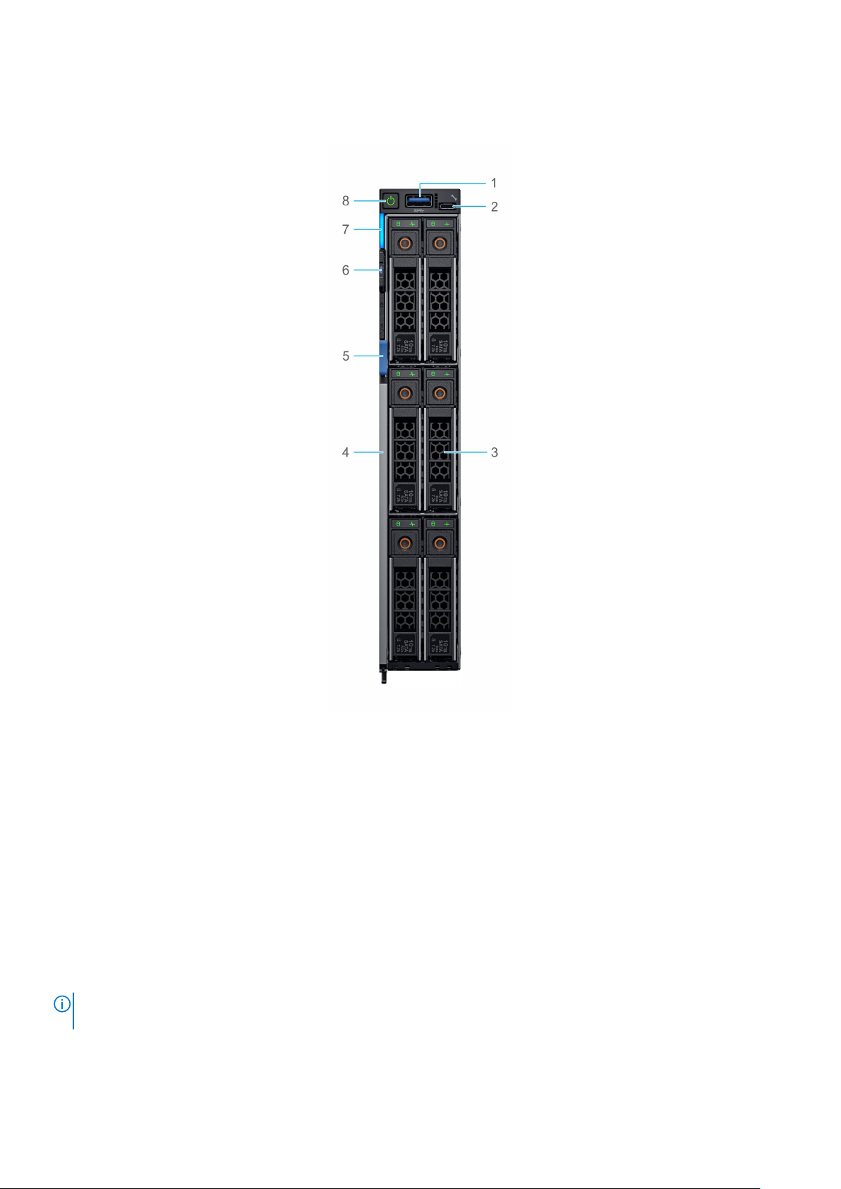
Front view of the system
Figure 1. Front view of the 6 drive configuration
1. USB 3.0 port
2. iDRAC direct port
3. Drives
4. Release handle
5. Release handle button
6. Information tag
7. System health and System ID indicator
8. Power button
For more information about the ports, see Technical Specifications.
Inside the system
Components that are hot swappable have orange touch points and the components that are not hot swappable
NOTE:
have blue touch points.
8 PowerEdge MX740c sled overview
Page 9
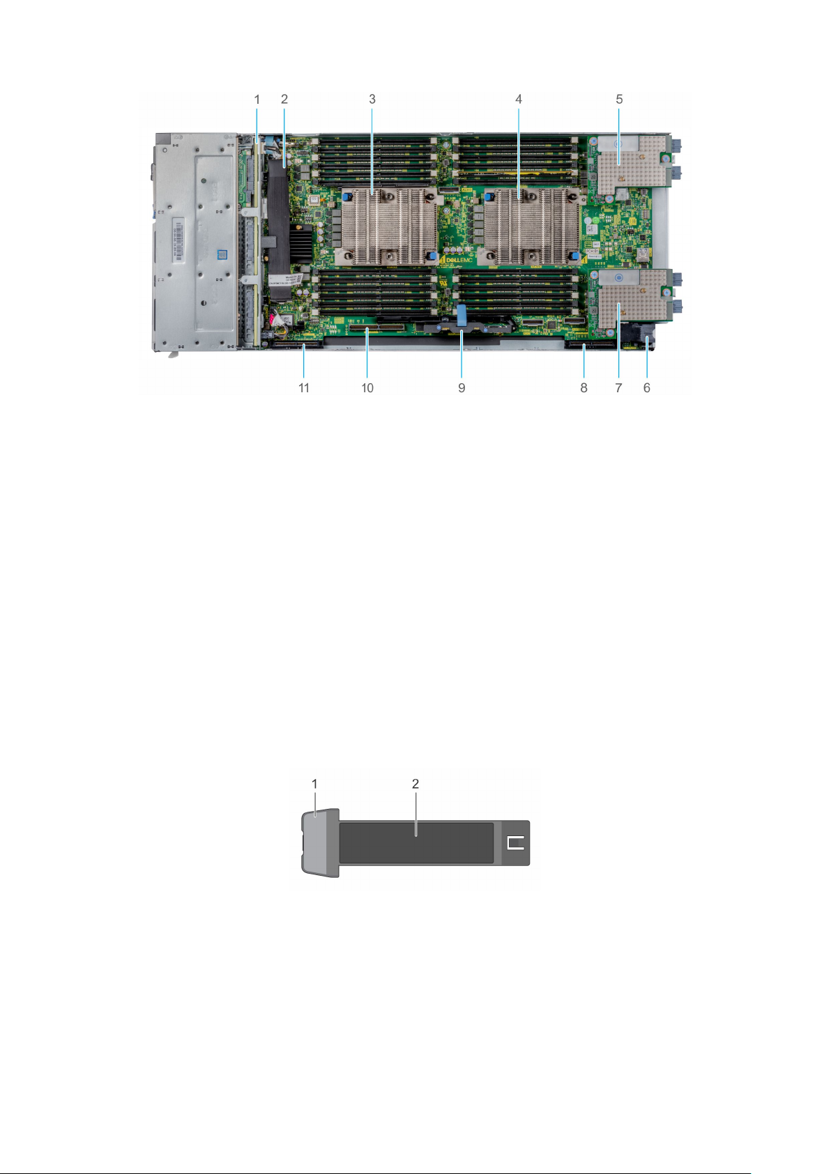
Figure 2. Inside the system
1. Backplane
2. Backplane cable
3. Processor 1 (heat sink)
4. Processor 2 (heat sink)
5. Mezzanine card A1
6. Power connector
7. Mezzanine card B1
8. Mini Mezzanine connector
9. iDRAC card
10. BOSS connector
11. PERC connector
Locating the Service Tag of your system
The System Information Tab contains the system's unique Express Service Code and Service Tag. This information is used by
Dell EMC to identify system configuration, warranty terms, and to route support calls to the appropriate personnel. A Quick
Resource Locator (QRL) label on the System Information Tab links to a web page that shows the exact factory configuration
and specific warranty purchased.
Figure 3. Locating Service Tag of your system
1. Information tag
2. Service tag
PowerEdge MX740c sled overview
9
Page 10
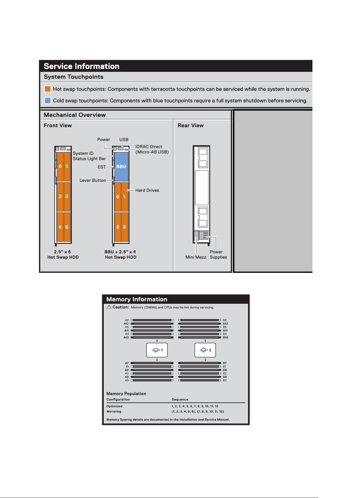
System information label
Figure 4. Mechanical overview
Figure 5. Memory information
10
PowerEdge MX740c sled overview
Page 11
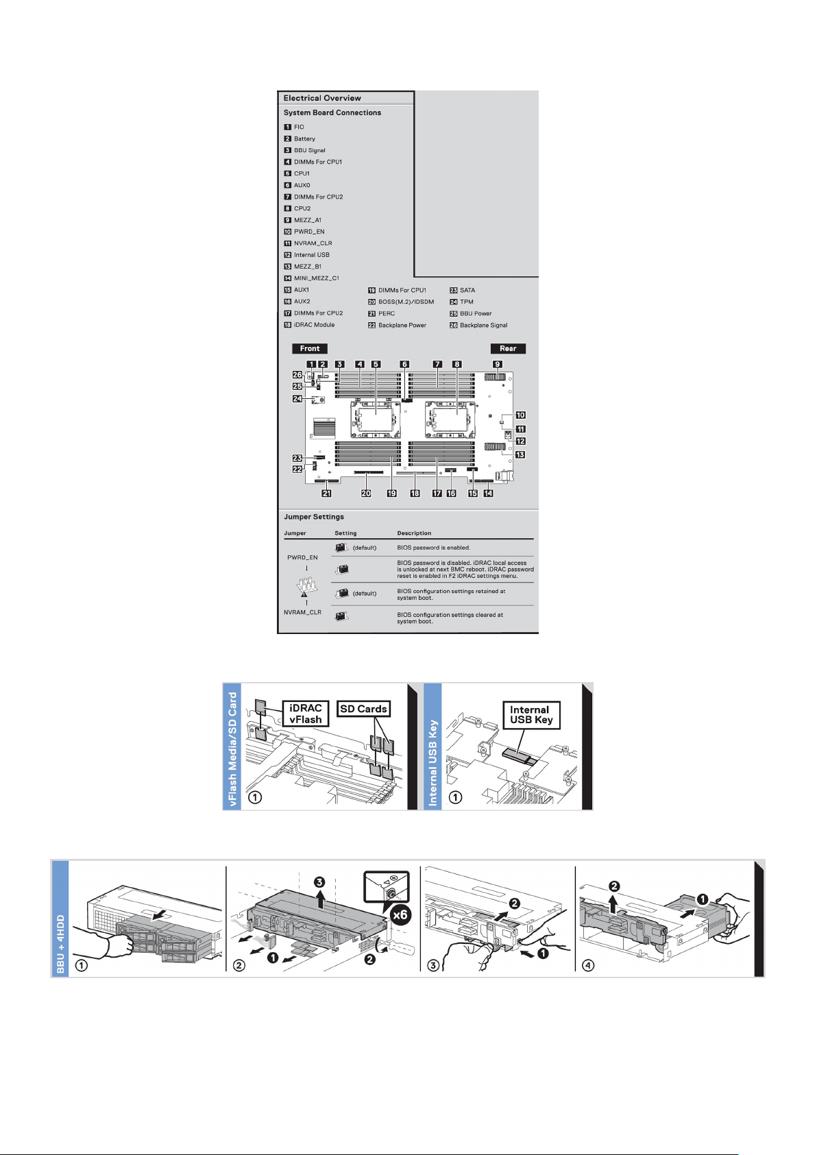
Figure 6. System board
Figure 7. Removal of IDSDM and Internal USB memory key(optional)
Figure 8. Removal of BBU module and drive cage
PowerEdge MX740c sled overview
11
Page 12
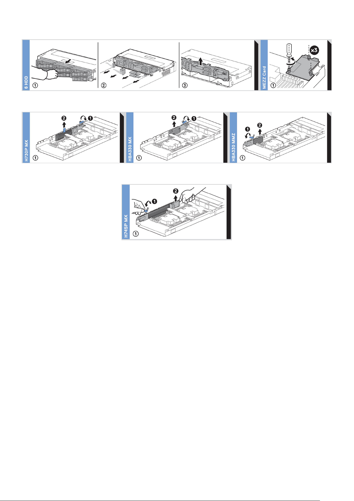
Figure 9. Removal of backplane and Mezzanine card
Figure 10. Removal of PERC cards and Mini Mezzanine card
Figure 11. Removal of Jumbo PERC card
12
PowerEdge MX740c sled overview
Page 13

Initial system setup and configuration
Topics:
• Setting up your system
iDRAC configuration
•
• Options to install the operating system
Setting up your system
Complete the following steps to set up your system:
Steps
1. Unpack the system.
2. Remove the I/O connector cover from the system connectors.
CAUTION: While installing the system, ensure that it is properly aligned with the slot on the enclosure to
prevent damage to the system connectors.
3
3. Install the system in the enclosure.
4. Turn on the enclosure.
NOTE: Wait for the enclosure to initialize before you press the power button.
5. Press the power button on the system.
Alternatively, you can also turn on the system by using iDRAC:
● For more information, see the Log in to iDRAC on page 14
● Open OpenManage Enterprise modular(OME modular), after the iDRAC is configured on the OME. For more information,
see the OME-modular User’s Guide at Dell.com/manuals.
iDRAC configuration
The Integrated Dell Remote Access Controller (iDRAC) is designed to make system administrators more productive and improve
the overall availability of Dell systems. iDRAC alerts administrators about system issues and enables them to perform remote
system management. This reduces the need for physical access to the system.
Options to set up iDRAC IP address
You must configure the initial network settings based on your network infrastructure to enable the communication to and from
iDRAC.
You can set up the IP address by using one of the following interfaces:
Interfaces
iDRAC Settings
utility
Dell Deployment
Toolkit
Document/Section
See Dell Integrated Dell Remote Access Controller User's Guide at www.dell.com/poweredgemanuals
See Dell Deployment Toolkit User’s Guide at www.dell.com/openmanagemanuals > OpenManage
Deployment Toolkit
Initial system setup and configuration 13
Page 14
Interfaces Document/Section
Dell Lifecycle
Controller
OME Modular See Dell OpenManagement Enterprise Modular User’s Guide at www.dell.com/openmanagemanuals
iDRAC Direct See Dell Integrated Dell Remote Access Controller User's Guide at www.dell.com/poweredgemanuals
See Dell Lifecycle Controller User’s Guide at www.dell.com/poweredgemanuals
Log in to iDRAC
You can log in to iDRAC as:
● iDRAC user
● Microsoft Active Directory user
● Lightweight Directory Access Protocol (LDAP) user
If you have opted for secure default access to iDRAC, you must use the iDRAC secure default password available on the system
Information tag. If you have not opted for secure default access to iDRAC, then use the default user name and password –root
and ca lvi n. You can also log in by using your Single Sign-On or Smart Card.
NOTE: You must have the iDRAC credentials to log in to iDRAC.
NOTE: Ensure that you change the default username and password after setting up the iDRAC IP address.
NOTE: The Intel Quick Assist Technology (QAT) on the Dell EMC PowerEdge MX740c is supported with chipset integration
and is enabled through an optional license. The license files are enabled on the sleds through iDRAC.
For more information about drivers, documentation, and white papers on the Intel QAT, see https://01.org/intel-quickassist-
technology.
For more information about logging in to the iDRAC and iDRAC licenses, see the latest Integrated Dell Remote Access Controller
User's Guide at www.dell.com/poweredgemanuals.
You can also access iDRAC by using RACADM. For more information, see the RACADM Command Line Interface Reference
Guide at www.dell.com/poweredgemanuals.
Options to install the operating system
If the system is shipped without an operating system, install the supported operating system by using one of the following
resources:
Table 1. Resources to install the operating system
Resources Location
iDRAC www.dell.com/idracmanuals
Lifecycle Controller www.dell.com/idracmanuals
OpenManage Deployment Toolkit www.dell.com/openmanagemanuals > OpenManage
Deployment Toolkit
Dell certified VMware ESXi www.dell.com/virtualizationsolutions
Installation and How-to videos for supported operating
systems on PowerEdge systems
NOTE: Virtual Media is optional for integrated Dell Remote Access Controllers (iDRAC) with an Enterprise license (iDRAC 7,
8 and 9) or module (iDRAC 6).It allows the usage of software image files (ISO-files), which can be used for installing
operating systems or updating servers.
Supported Operating Systems for Dell PowerEdge Systems
14 Initial system setup and configuration
Page 15
Methods to download firmware and drivers
You can download the firmware and drivers by using any of the following methods:
Table 2. Firmware and drivers
Methods Location
From the Dell EMC support site www.dell.com/support/home
Using Dell Remote Access Controller Lifecycle Controller
(iDRAC with LC)
Using Dell Repository Manager (DRM) www.dell.com/openmanagemanuals > Repository Manager
Using Dell OpenManage Essentials www.dell.com/openmanagemanuals > OpenManage Essentials
Using Dell OpenManage Enterprise www.dell.com/openmanagemanuals > OpenManage
Using Dell Server Update Utility (SUU) www.dell.com/openmanagemanuals > Server Update Utility
Using Dell OpenManage Deployment Toolkit (DTK) www.dell.com/openmanagemanuals > OpenManage
Using iDRAC virtual media www.dell.com/idracmanuals
www.dell.com/idracmanuals
Enterprise
Deployment Toolkit
Downloading drivers and firmware
Dell EMC recommends that you download and install the latest BIOS, drivers, and systems management firmware on your
system.
Prerequisites
Ensure that you clear the web browser cache before downloading the drivers and firmware.
Steps
1. Go to www.dell.com/support/home.
2. In the Drivers & Downloads section, type the Service Tag of your system in the Enter a Service Tag or product ID box,
and then click Submit.
NOTE:
If you do not have the Service Tag, select Detect Product to allow the system to automatically detect the
Service Tag, or click View products, and navigate to your product.
3. Click Drivers & Downloads.
The drivers that are applicable to your system are displayed.
4. Download the drivers to a USB drive, CD, or DVD.
Initial system setup and configuration
15
Page 16

Installing and removing system components
Topics:
• Safety instructions
Before working inside your sled
•
• After working inside your sled
• Recommended tools
• PowerEdge MX740c sled
• System cover
• Air shroud
• Drives
• Drive backplane
• Cable routing
• Drive cage
• Battery backup unit
• Control panel
• System memory
• Processors and heat sinks
• iDRAC card
• PERC card
• Optional Internal dual SD module
• M.2 BOSS module
• Mezzanine card
• Optional internal USB memory key
• System battery
• System board
• Trusted Platform Module
4
Safety instructions
NOTE:
Whenever you need to lift the system, get others to assist you. To avoid injury, do not attempt to lift the system by
yourself.
WARNING: Opening or removing the system cover while the system is powered on may expose you to a risk of
electric shock.
CAUTION: Do not operate the system without the cover for a duration exceeding five minutes. Operating the
system without the system cover can result in component damage.
CAUTION: Many repairs may only be done by a certified service technician. You should only perform
troubleshooting and simple repairs as authorized in your product documentation, or as directed by the online or
telephone service and support team. Damage due to servicing that is not authorized by Dell is not covered by
your warranty. Read and follow the safety instructions that are shipped with your product.
NOTE: It is recommended that you always use an antistatic mat and antistatic strap while working on components inside
the system.
CAUTION: To ensure proper operation and cooling, all bays in the system and system fans must be always
populated with a component or a blank.
16 Installing and removing system components
Page 17

Before working inside your sled
Prerequisites
Follow the safety guidelines listed in Safety instructions on page 16.
Steps
1. Power off the sled.
2. Remove the sled from the enclosure.
3. If applicable install the I/O connector cover.
CAUTION: To prevent damage to the I/O connectors on the system, ensure that you cover the connectors
when you remove the system from the enclosure.
4. Remove the system cover.
After working inside your sled
Prerequisites
Follow the safety guidelines listed in Safety instructions on page 16.
Steps
1. Install the system cover.
2. If installed, remove the I/O connector cover on the system.
CAUTION: To prevent damage to the I/O connectors, do not touch the connectors or the connector pins.
3. Install the sled in the enclosure.
4. Power on the sled.
NOTE: Ability to power on the sled requires iDRAC to fully initialize first.
Recommended tools
You need the following tools to perform the removal and installation procedures:
● Phillips #1 and Phillips #2 screwdrivers
● Torx T15 and T30 screwdrivers
● Wrist grounding strap
PowerEdge MX740c sled
The PowerEdge MX740c sled is a server unit that is installed into the PowerEdge MX7000 enclosure.
Removing the sled from enclosure
Prerequisites
1. Follow the safety guidelines listed in Safety Instructions.
2. Power off the sled.
Installing and removing system components
17
Page 18
Steps
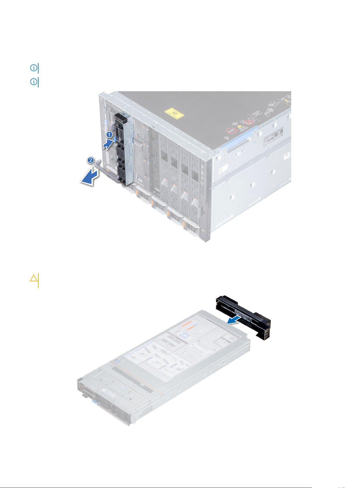
1. Press the blue release button on the sled to release the sled handle.
2. Holding the sled handle, slide the sled out of the enclosure.
NOTE: Support the system with both hands while sliding it out of the enclosure.
NOTE: Removing the sled with the enclosure powered on is supported if you shut down the sled before removal.
Figure 12. Removing the sled from enclosure
3. Install the I/O connector cover on the sled.
CAUTION:
from the enclosure.
To protect the I/O connector pins, install the I/O connector cover every time a sled is removed
Figure 13. Installing the I/O connector cover on sled
18
Installing and removing system components
Page 19
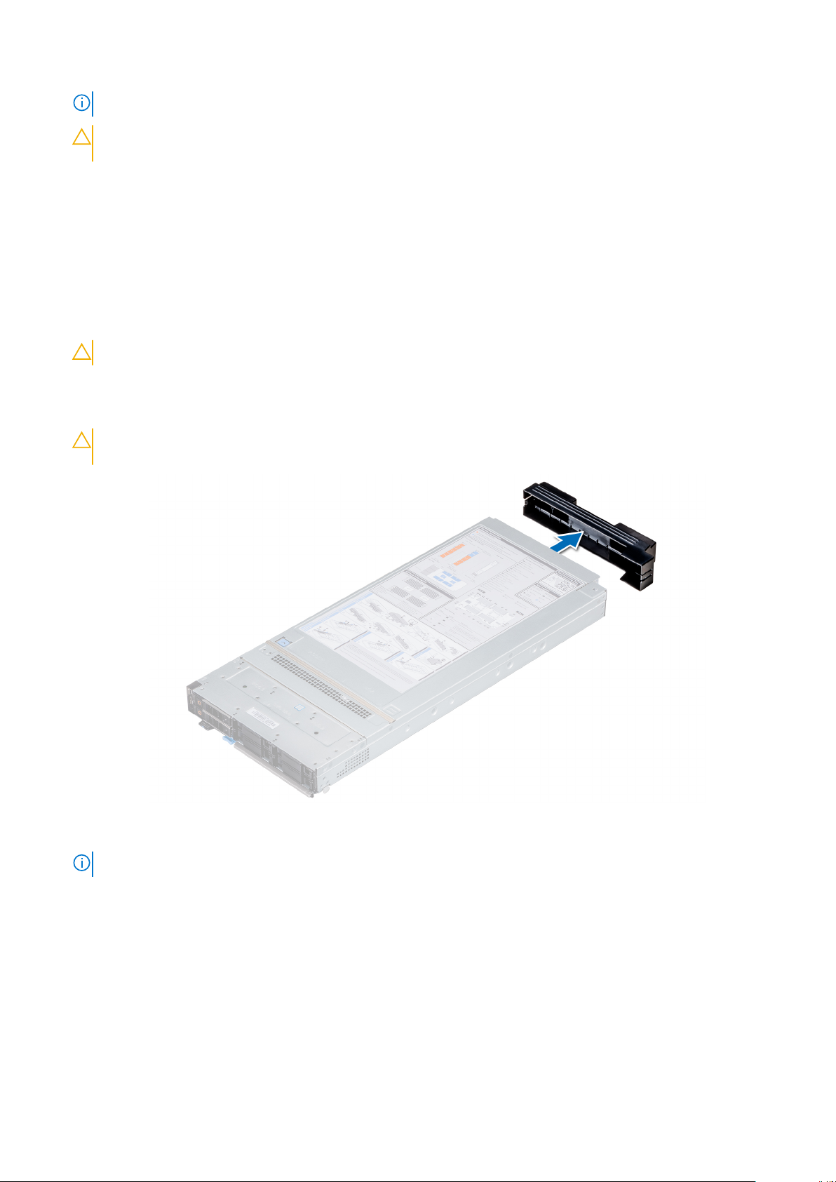
NOTE: The color of the I/O connector cover may differ.
CAUTION: If you are permanently removing the sled, install a sled blank promptly. Operating the enclosure
without a blank, for an extended time can result in overheating or performance loss.
Next steps
1. Install the sled or the sled blank into the enclosure.
Installing the sled into enclosure
Prerequisites
1. Follow the safety guidelines listed in Safety instructions on page 16.
CAUTION: To prevent damage to the I/O connectors, do not touch the connectors or the connector pins.
Steps
1. Remove the I/O connector cover from the I/O connector(s) and store for future use.
CAUTION: To protect the I/O connector pins, install the I/O connector cover every time a sled is removed
from the enclosure.
Figure 14. Removing the I/O connector cover from sled
NOTE: The color of the I/O connector cover may differ.
2. Press the blue release button on the sled to release the sled handle.
3. Holding the sled with both hands, align the sled with the compute sled-bay in the enclosure.
4. Slide the sled into the enclosure, until the sled handle is in the lock position.
5. Push the sled handle inwards so that it locks into place to secure the sled in the enclosure.
Installing and removing system components
19
Page 20
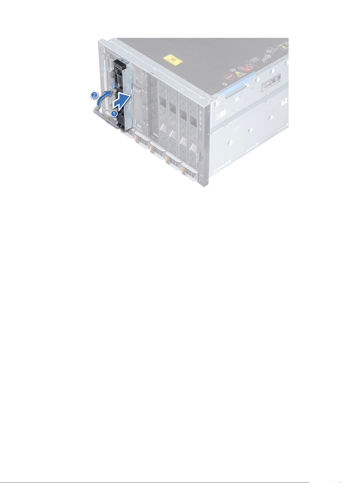
Figure 15. Installing the sled into enclosure
Next steps
1. Power on the sled.
System cover
The system cover protects the components inside the system and helps in maintaining air flow inside the system.
Removing the system cover
Prerequisites
1. Follow the safety guidelines listedin Safety instructions on page 16.
2. Power off the sled.
3. Remove the sled from the enclosure.
4. Place the sled on the flat surface with the top cover facing upwards.
Steps
1. Press the blue release tab on the system cover and slide the cover towards the rear of the system.
2. Hold the cover on both sides, and lift the cover away from the system.
20
Installing and removing system components
Page 21
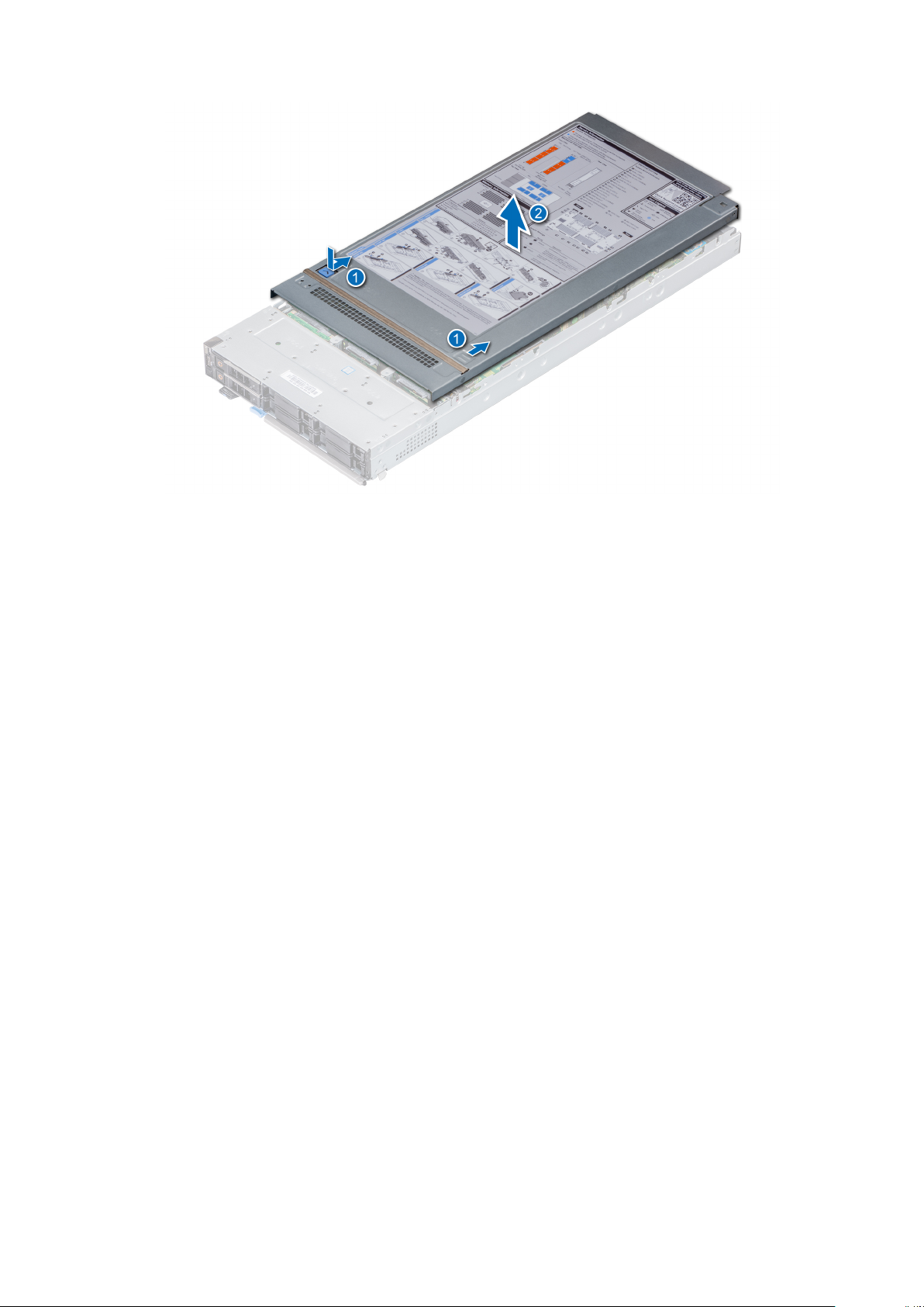
Figure 16. Removing system cover
Next steps
1. Replace the system cover.
Installing system cover
Prerequisites
1. Follow the safety guidelines listed in Safety instructions on page 16.
2. Ensure that all internal cables are routed correctly and connected, and no tools or extra parts are left inside the system.
Steps
1. Align the tabs on the system cover with the guide slots on the system.
2. Slide the cover towards the front of the system.
Installing and removing system components
21
Page 22

Figure 17. Installing system cover
Next steps
1. Install the sled into the enclosure.
2. Turn on the sled.
22
Installing and removing system components
Page 23
Air shroud
The air shroud aerodynamically directs the airflow across the entire system. The airflow passes air through all the critical parts
of the system thus allowing increased cooling preventing overheating.
Removing air shroud
Prerequisites
CAUTION: Never operate your system with the air shroud removed. The system may get overheated quickly,
resulting in shutdown of the system and loss of data.
1. Follow the safety guidelines listed in Safety Instructions.
2. Follow the procedure listed in Before working inside your sled on page 17.
Steps
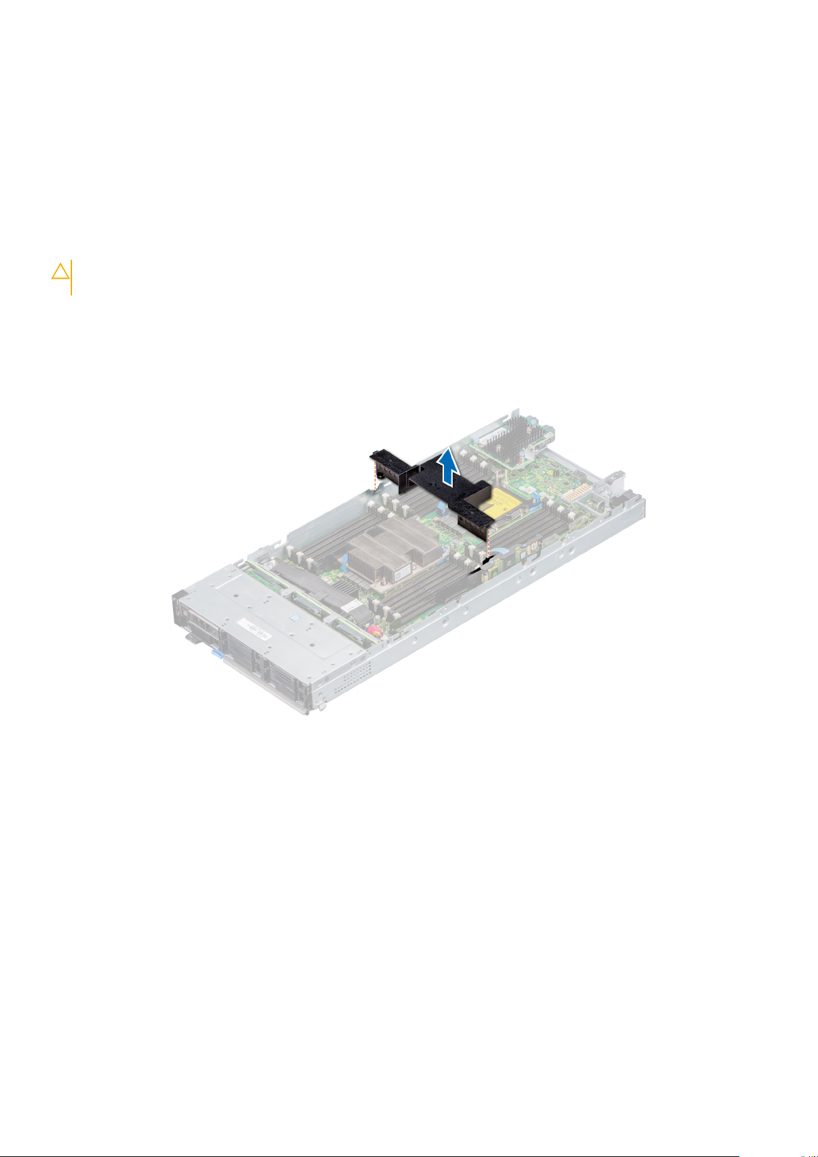
Hold both the edges of the air shroud and lift it out of the system.
Figure 18. Removing air shroud
Next steps
1. Install the air shroud.
Installing air shroud
Prerequisites
1. Follow the safety guidelines listed in Safety Instructions.
2. Follow the procedure listed in Before working inside your sled on page 17.
Steps
1. Align the air shroud with the guide slots on the system.
2. Lower the air shroud into the system until it is firmly seated.
Installing and removing system components
23
Page 24
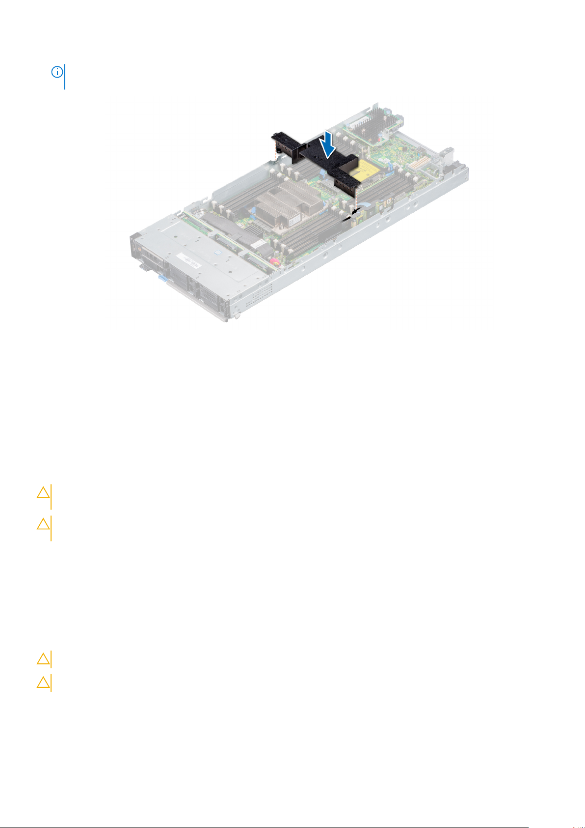
NOTE: When firmly seated, the memory socket and processor numbers marked on the air shroud aligns with the
respective memory socket and processor numbers marked on the system.
Figure 19. Installing air shroud
Next steps
1. Follow the procedure listed in After working inside the sled.
Drives
Your system supports 2.5-inch SAS/SATA SSD, NVMe drives and PCIe SSDs. The drives or SSDs are supplied in a hotswappable drive carriers that fit in the drive bays and these drives connect to the system board through the drive backplane.
CAUTION:
ensure that the host adapter is configured correctly to support hot-swap drive removal and insertion.
CAUTION: Do not turn off or restart your system while the drive is being formatted. Doing so can cause a drive
failure.
When you format a drive, allow enough time for the formatting to be complete. The high-capacity drives can take a long time to
format.
Removing drive blank
Prerequisites
1. Follow the safety guidelines listed in Safety instructions on page 16
CAUTION: Mixing drive blanks from previous generations of PowerEdge servers is not supported
Before attempting to remove or install a drive while the system is running, see the documentation to
CAUTION: To maintain proper system cooling, all empty drive slots must have drive blanks installed.
Steps
Press the release button and slide the drive blank out of the drive slot.
24
Installing and removing system components
Page 25
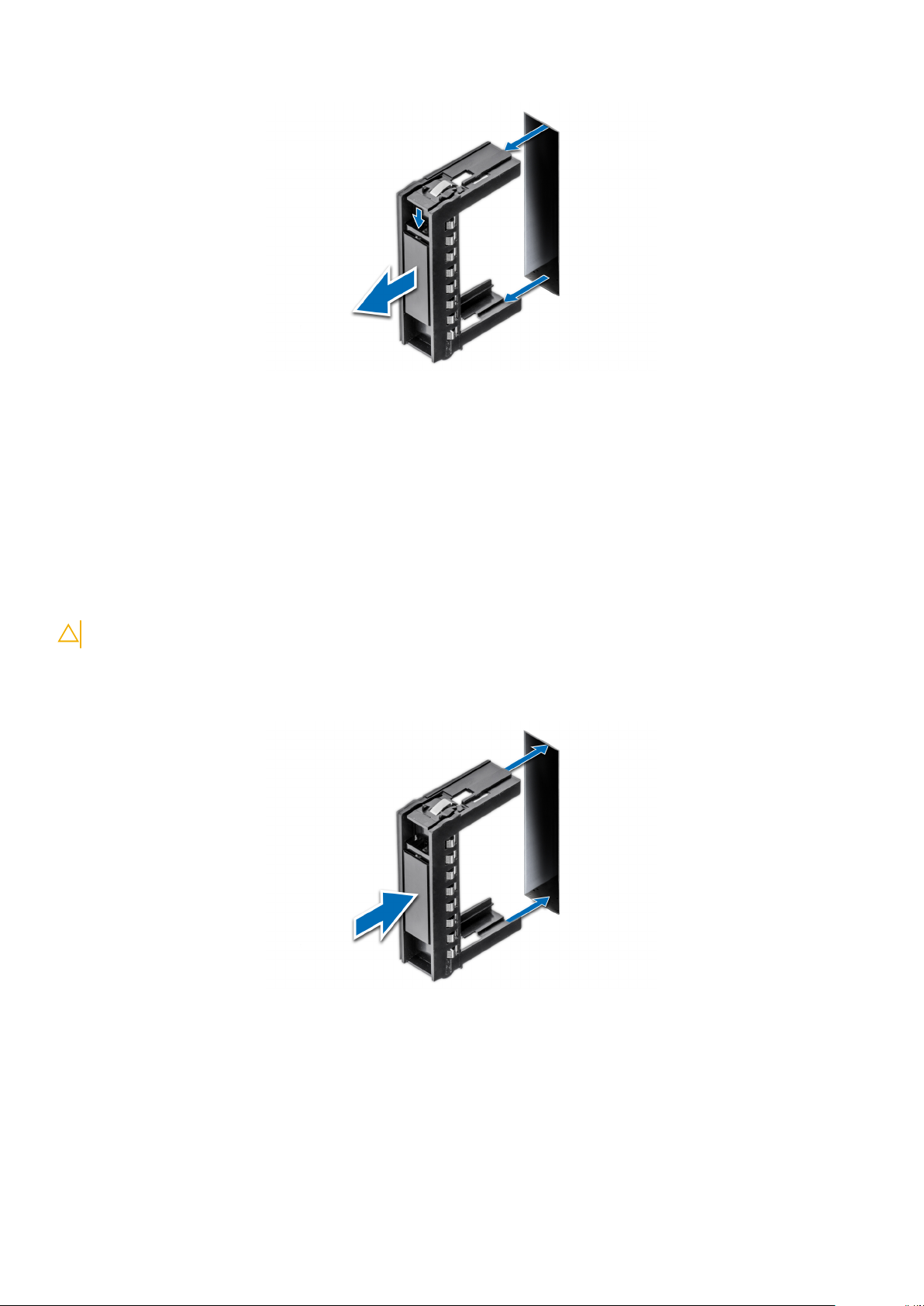
Figure 20. Removing drive blank
Next steps
1. Install a drive or a drive blank.
Installing drive blank
Prerequisites
1. Follow the safety guidelines listed in Safety instructions on page 16.
CAUTION: Mixing drive blanks from previous generations of PowerEdge servers is not supported.
Steps
Insert the drive blank into the drive slot and push the blank until the release button clicks into place.
Figure 21. Installing drive blank
Removing drive carrier
Prerequisites
1. Follow the safety guidelines listed in Safety instructions on page 16.
2. Using the management software, prepare the drive for removal.
Installing and removing system components
25
Page 26
If the drive is online, the green activity or fault indicator flashes while the drive is turning off. When the drive indicators are
off, the drive is ready for removal. For more information, see the documentation for the storage controller.
CAUTION: Before attempting to remove or install a drive while the system is running, see the documentation for
the storage controller card to ensure that the host adapter is configured correctly to support drive removal and
insertion.
CAUTION: Mixing drive carriers from previous generations or other platforms of PowerEdge servers is not
supported.
CAUTION: To prevent data loss, ensure that your operating system supports hot-swap drive installation. See the
documentation supplied with your operating system.
CAUTION: To maintain proper system cooling, all empty drive bays must have drive blanks installed.
WARNING: Ensure that you back up your data, before removing a drive. For more information about preparing
your drive for removal and supported RAID redundancy, see the Troubleshooting guide of your system at
www.dell.com/poweredgemanuals.
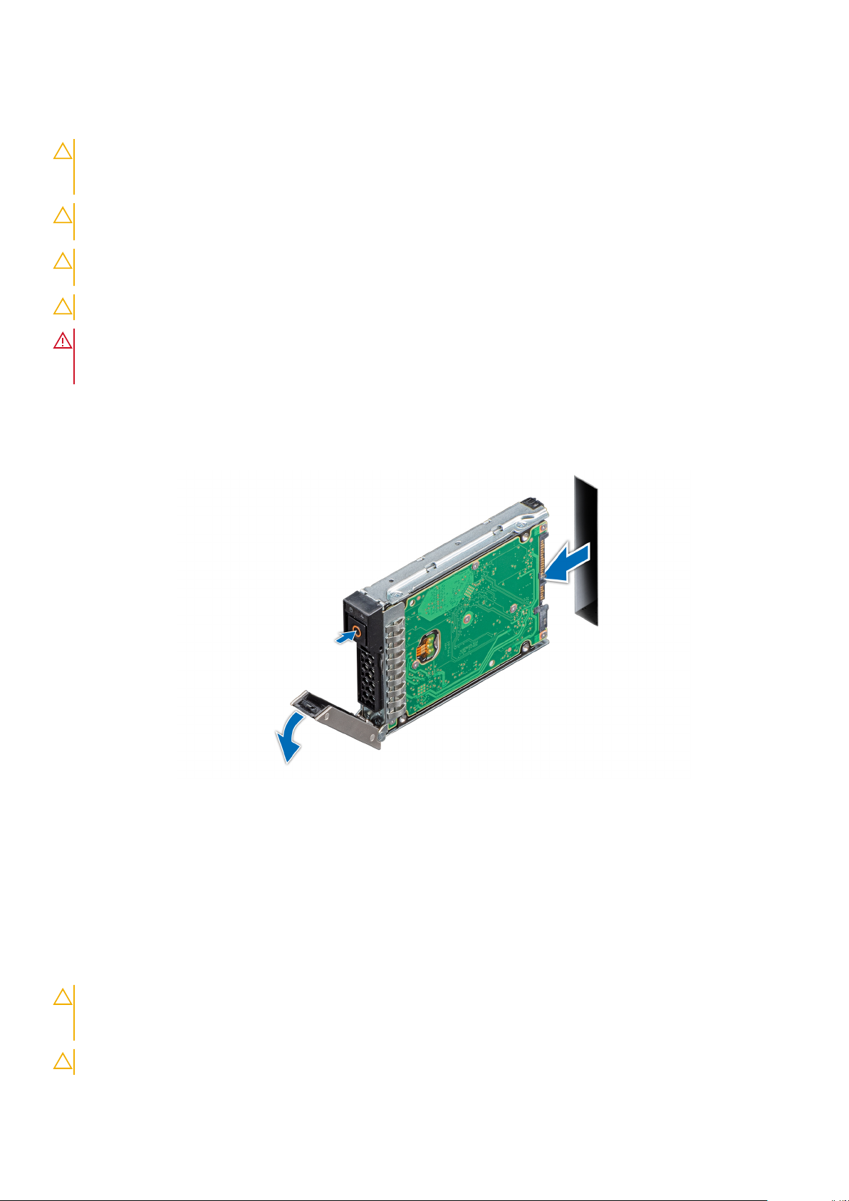
Steps
1. Press the release button to open the release handle.
2. Holding the handle, slide the drive carrier out of the drive slot.
Figure 22. Removing drive carrier
Next steps
1. Replace the drive carrier or a drive blank.
Installing drive carrier
Prerequisites
CAUTION:
the storage controller card to ensure that the host adapter is configured correctly to support drive removal and
insertion.
CAUTION: Mixing drive carriers from previous generations of PowerEdge servers is not supported.
26 Installing and removing system components
Before attempting to remove or install a drive while the system is running, see the documentation for
Page 27
CAUTION: Combining SAS and SATA drives in the same RAID volume is not supported.
CAUTION: When installing a drive carrier, ensure that the adjacent drives are fully installed. Inserting a drive
carrier and attempting to lock its handle next to a partially installed carrier can damage the partially installed
carrier's shield spring and make it unusable.
CAUTION: To prevent data loss, ensure that your operating system supports hot-swap drive installation. See the
documentation supplied with your operating system.
CAUTION: When a replacement hot swappable drive is installed and the system is powered on, the drive
automatically begins to rebuild. Ensure that the replacement drive is blank or contains data that you wish to
overwrite. Any data on the replacement drive is immediately lost after the drive is installed.
1. Follow the safety guidelines listed in the Safety instructions.
2. If installed, remove the drive blank.
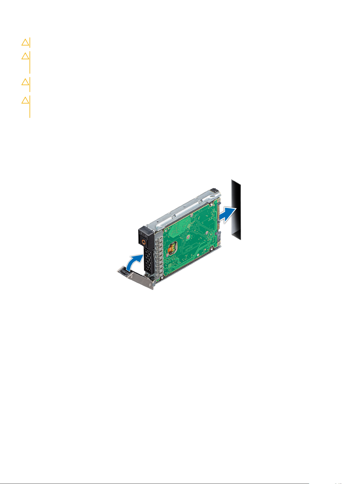
Steps
1. Press the release button on the front of the drive carrier to open the release handle.
2. Insert the drive carrier into the drive slot and slide until the drive carrier connects with the backplane.
3. Close the release handle of the drive carrier to lock the drive in place.
Figure 23. Installing drive carrier
Removing a drive from drive carrier
Prerequisites
1. Follow the safety guidelines listed in Safety instructions on page 16.
2. Remove the drive carrier.
Steps
1. Using the Phillips #1 screwdriver, remove the screws from the slide rails on the drive carrier.
2. Lift the drive out of the drive carrier.
Installing and removing system components
27
Page 28
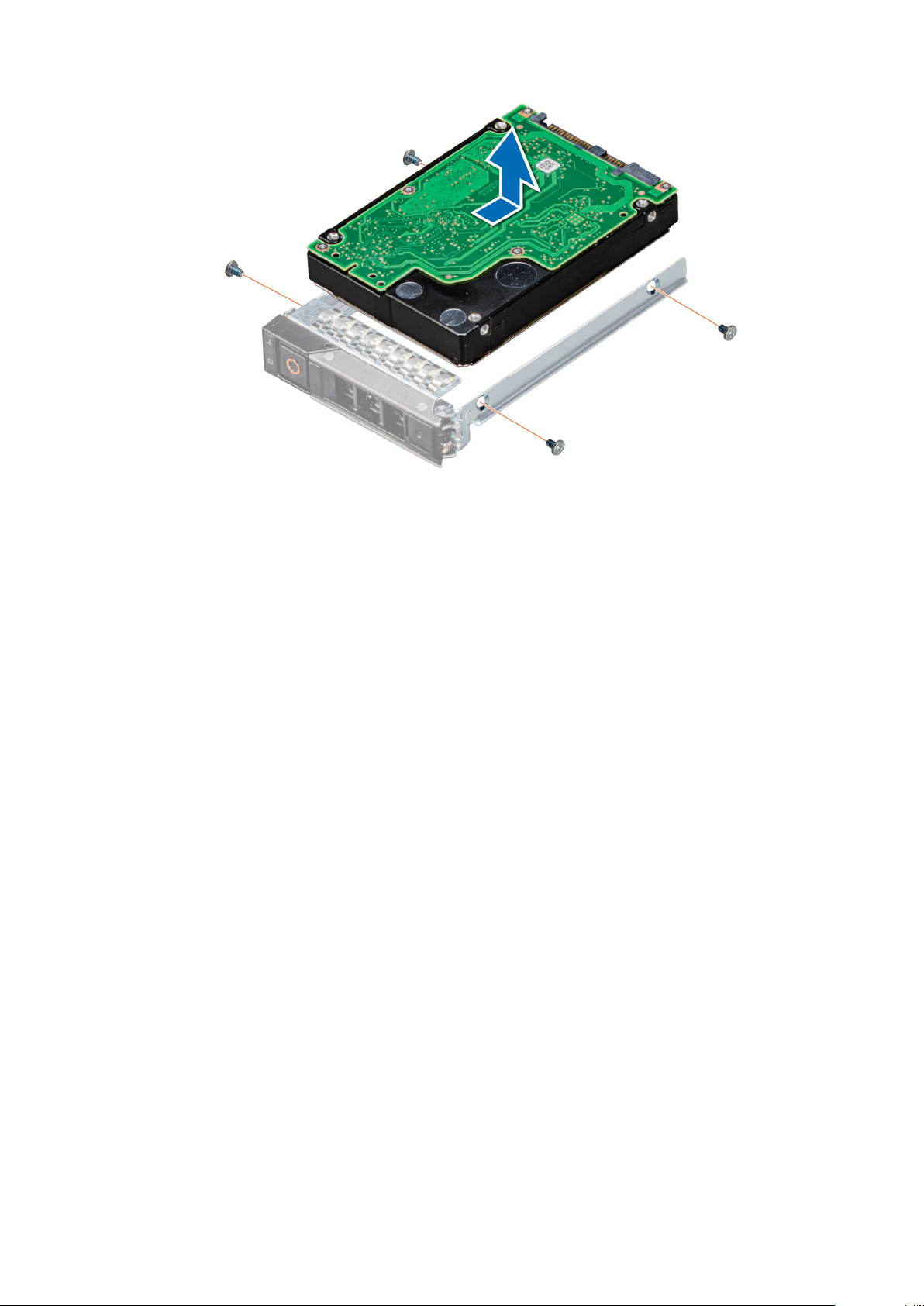
Figure 24. Removing a drive from drive carrier
Next steps
1. Replace the drive into the drive carrier.
Installing a drive into drive carrier
Prerequisites
1. Follow the safety guidelines listed in Safety instructions on page 16
Steps
1. Insert the drive into the drive carrier, with the connector end of the drive towards the back of the carrier.
2. Align the screw holes on the drive with the screw holes on the drive carrier.
3. Using the Phillips #1 screwdriver, replace the screws to secure the drive to the drive carrier.
28
Installing and removing system components
Page 29
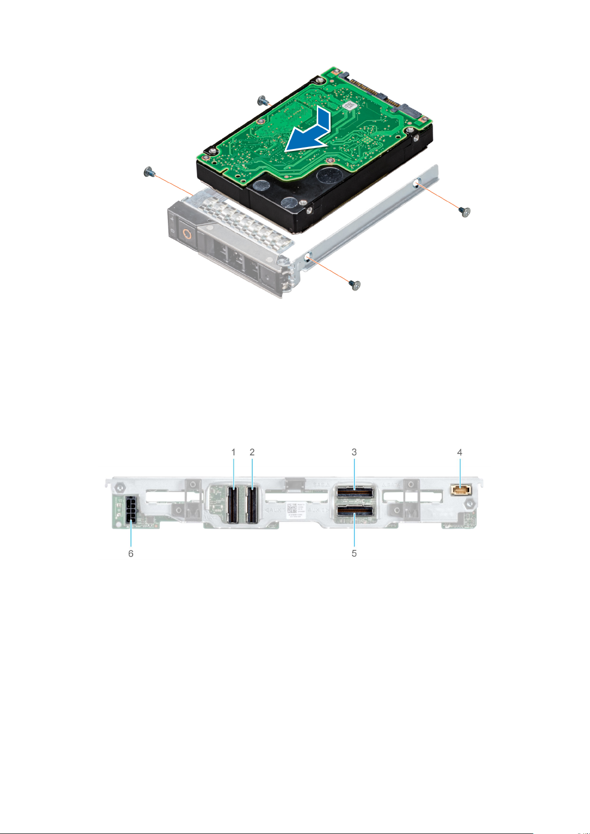
Figure 25. Installing a drive into drive carrier
Drive backplane
Depending on the configuration, your system supports:
● 2.5 inch (x6) Universal backplane
● 2.5 inch (x6) SAS/SATA backplane
● 2.5 inch (x4) Universal backplane
Figure 26. 6 x 2.5-inch universal backplane
1. AUX 2 cable connector
2. AUX 1 cable connector
3. SAS/SATA connector
4. Signal cable connector
5. AUX 0 cable connector
6. Power cable connector
Installing and removing system components
29
Page 30
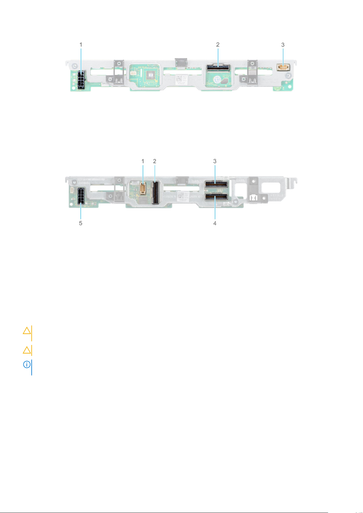
Figure 27. 6 x 2.5-inch SAS/SATA backplane
1. Power cable connector
2. SAS/SATA connector
3. Signal cable connector
Figure 28. 4 x 2.5-inch universal backplane
1. Signal cable connector
2. AUX 1 cable connector
3. SAS/SATA connector
4. AUX 0 cable connector
5. Power cable connector
Removing drive backplane
Prerequisites
CAUTION:
system before removing the drive backplane. For more information, see Removing a drive carrier.
CAUTION: Temporarily label drives before you remove the drive so that you can replace them in the same slots.
NOTE: Observe the routing of the cable as you remove it from the sled. Route the cable properly when you replace it, to
prevent the cable from being pinched or crimped.
1. Follow the safety guidelines listed in Safety Instructions.
2. Follow the procedure listed in Before working inside your sled.
3. Disconnect the cables connected to the backplane.
4. Remove the drives.
Steps
1. Hold the drive backplane by the edges and lift it upwards to disengage the backplane from the guide pins.
2. Lift the backplane out of the sled.
To prevent damage to the drives and the drive backplane, you must remove the drives from the
30
Installing and removing system components
Page 31

Figure 29. Removing drive backplane
Next steps
1. Replace the drive backplane.
Installing drive backplane
Prerequisites
1. Follow the safety guidelines listed in Safety instructions on page 16
2. Follow the procedure listed in Before working inside the sled.
Steps
1. Verify backplane connector pins are not bent and then connect the signal cable to the backplane.
2. Align the guide pins on the drive backplane with the sled.
3. Lower the drive backplane, until it is fully seated.
NOTE: To install the backplane, ensure the two pins on the backplane tab seat into the two slots on the system chassis.
Installing and removing system components 31
Page 32

Figure 30. Installing drive backplane
Next steps
1. Connect the incoming power cable to the backplane and then verify both power and signal cable connections are fully seated
to the backplane and system board.
2. Connect the integrated cable to the backplane and system board if there is no PERC card installed in the system.
3. Install the drives.
4. Follow the procedure listed in After working inside the sled.
Cable routing
Figure 31. Cable routing - 4 x 2.5-inch backplane BBU cabling.
32
Installing and removing system components
Page 33

Figure 32. Cable routing - 4 x 2.5-inch backplane with internal PERC card
Figure 33. Cable routing - 4 x 2.5 PCIe backplane with Jumbo PERC card
Installing and removing system components
33
Page 34

Figure 34. Cable routing - 6 x 2.5-inch SAS/SATA backplane with internal PERC card
Figure 35. Cable routing - 6 x 2.5-inch SAS/SATA backplane with Jumbo PERC card
34
Installing and removing system components
Page 35

Figure 36. Cable routing - 6 x 2.5-inch SAS/SATA backplane SATA cabling
Figure 37. Cable routing - 6 x 2.5-inch backplane with internal PERC card
Installing and removing system components
35
Page 36

Figure 38. Cable routing - 6 x 2.5-inch backplane with Jumbo PERC card
Figure 39. Cable routing - 6 x 2.5-inch backplane SATA cabling
Drive cage
The drive cage contains the drives and the battery backup unit module.
Removing the drive cage
Prerequisites
CAUTION:
removing the backplane.
CAUTION: Temporarily label drives before you remove the drives so that you can replace them in the same slots.
36 Installing and removing system components
To prevent damage to the drives and backplane, you must remove the drives from the system before
Page 37

NOTE: Observe the routing of the cables on the chassis as you remove them from the system. You must route these cables
properly when you replace them to prevent the cables from being pinched or crimped.
1. Follow the safety guidelines listed in Safety instructions on page 16.
2. Follow the procedure listed in Before working inside your sled on page 17.
3. Disconnect the cables connected to the backplane.
4. Remove the drives
5. Remove the drive backplane.
Steps
1. Using the Phillips #1 screwdriver, remove the screws that secure the drive cage to the sled.
2. Lift the drive cage away from the sled.
Figure 40. Removing the drive cage
Next steps
1. Replace the drive cage.
Installing the drive cage
Prerequisites
1. Follow the safety guidelines listed in Safety Instructions.
2. Follow the procedure listed in Before working inside the sled.
Steps
1. Place the drive cage into the system, aligning with the screw holes on the system.
2. Using the Phillips #1 screwdriver, secure the drive cage in place with screws.
Installing and removing system components
37
Page 38

Figure 41. Installing the drive cage
Next steps
1. Install the drive backplane.
2. Install the drives.
3. Follow the procedure listed in After working inside your sled on page 17.
Battery backup unit
Removing the battery backup unit
Prerequisites
1. Follow the safety guidelines listed in Safety Instructions.
2. Follow the procedure listed in Before working inside your sled on page 17.
3. Remove the drives.
4. Disconnect the battery backup unit (BBU) cable from the system board.
5. Disconnect the backplane cables.
6. Remove the drive cage.
7. Remove the drive backplane.
Steps
1. Press the latch on the side of the drive cage to release the BBU module.
2. Holding the BBU module by the edges, slide the BBU module out of the system.
38
Installing and removing system components
Page 39

Figure 42. Removing the BBU module
Next steps
1. Replace the BBU in the cage.
2. Replace the BBU module.
Installing the battery backup unit
Prerequisites
1. Follow the safety guidelines listed in Safety Instructions.
2. Follow the procedure listed in Before working inside your sled on page 17.
3. Install the BBU into the BBU cage.
4. Install the drive cage.
5. Install the backplane.
Steps
1. Route the cable on the battery backup unit (BBU) through the front end of the drive cage.
2. Align and slide the BBU until it firmly locks in place with the drive cage.
Installing and removing system components
39
Page 40

Figure 43. Installing the BBU
3. Connect the BBU cables to the connector on the system board.
Next steps
1. Follow the procedure listed in the After working inside your sled.
2. Replace the drive carrier or a drive blank.
Removing the BBU from the BBU cage
Prerequisites
1. Follow the safety guidelines listed in Safety Instructions.
2. Follow the procedure listed in the Before working inside your sled.
3. Remove the BBU module.
Steps
1. Using a Phillips #1 screwdriver, loosen the captive screw securing the BBU to the BBU cage.
2. Lift and slide the BBU out of the BBU cage.
40
Installing and removing system components
Page 41

Figure 44. Removing the BBU from the BBU cage
Next steps
1. Install the BBU into the BBU cage.
Installing the BBU into the BBU cage
Prerequisites
1. Follow the safety guidelines listed in Safety Instructions.
Steps
1. Align and slide the BBU into the BBU cage.
2. Using a Phillips #1 screwdriver, tighten the captive screw to secure the BBU to the BBU cage.
Installing and removing system components
41
Page 42

Figure 45. Installing the BBU into the BBU cage
Next steps
1. Install the BBU module.
Control panel
The control panel allows you to manually control the inputs to the sled.
Removing the control panel
Prerequisites
1. Follow the safety guidelines listed in Safety Instructions.
2. Follow the procedure listed in Before working inside the sled.
3. Remove the drives.
4. Remove the drive cage.
Steps
1. Pull the blue strap to disconnect the control panel cable connected to the system board.
2. Using a Phillips #1 screwdriver, remove the screws that secure the control panel to the system.
3. Slide the control panel out of the system.
42
Installing and removing system components
Page 43

Figure 46. Removing the control panel
Next steps
1. Install the control panel.
Installing the control panel
Prerequisites
1. Follow the safety guidelines listed in Safety Instructions.
2. Follow the procedure listed in Before working inside your sled.
Steps
1. Align control panel with the slots on the system and slide it in.
2. Connect the control panel cable to the connector on the system board.
3. Using a Phillips #1 screwdriver, secure the control panel to the system with the screws.
Installing and removing system components
43
Page 44

Figure 47. Installing the control panel
Next steps
1. Install the drive cage.
2. Install the drives.
3. Follow the procedure listed in the After working inside your sled.
System memory
The system supports DDR4 registered DIMMs (RDIMMs), load reduced DIMMs (LRDIMMs), Non-Volatile DIMMs (NVDIMMNs), and Intel Optane Data Center Persistent Memory Modules (DCPMMs). System memory holds the instructions that are
executed by the processor.
Your system contains 24 memory sockets split into two sets of 12 sockets, one set per processor. Each 12-socket set is
organized into six channels. Six memory channels are allocated to each processor. In each channel, the release tabs of the first
socket are marked white, and the second socket black.
44
Installing and removing system components
Page 45

Figure 48. System memory layout
Memory channels are organized as follows:
Table 3. Memory channels
Channel Processor 1 Processor 2
0 Slots A1 and A7 Slots B1 and B7
1 Slots A2 and A8 Slots B2 and B8
2 Slots A3 and A9 Slots B3 and B9
3 Slots A4 and A10 Slots B4 and B10
4 Slots A5 and A11 Slots B5 and B11
5 Slots A6 and A12 Slots B6 and B12
Table 4. Memory population
DIMM Type DIMM Ranking Voltage Operating Frequency (in MT/s)
RDIMM 1R / 2R 1.2 V 2933, 2666
LRDIMM 4R / 8R
1.2 V 2666
Installing and removing system components 45
Page 46

General memory module installation guidelines
To ensure optimal performance of your system, observe the following general guidelines when configuring your system memory.
If your system's memory configurations fail to observe these guidelines, your system might not boot, stop responding during
memory configuration, or operate with reduced memory.
The memory bus may operate at frequency can be 2933 MT/s, 2666 MT/s, 2400 MT/s, or 2133 MT/s depending on the
following factors:
● System profile selected (for example, Performance Optimized, or Custom [can be run at high speed or lower])
● Maximum supported DIMM speed of the processors. For memory frequency of 2933 MT/s, one DIMM per channel is
supported.
● Maximum supported DIMM speed of the processors.
● Maximum supported speed of the DIMMs
NOTE: MT/s indicates DIMM speed in MegaTransfers per second.
The system supports Flexible Memory Configuration, enabling the system to be configured and run in any valid chipset
architectural configuration. The following are the recommended guidelines for installing memory modules:
● All DIMMs must be DDR4.
● RDIMMs and LRDIMMs must not be mixed.
● 64 GB LRDIMMs that are DDP (Dual Die Package) LRDIMMs must not be mixed with 128 GB LRDIMMs that are TSV
(Through Silicon Via/3DS) LRDIMMs.
● x4 and x8 DRAM based memory modules can be mixed.
● Up to two RDIMMs can be populated per channel regardless of rank count.
● Up to two LRDIMMs can be populated per channel regardless of rank count.
● A maximum of two different ranked DIMMs can be populated in a channel regardless of rank count.
● If memory modules with different speeds are installed, they will operate at the speed of the slowest installed memory
module(s).
● Populate memory module sockets only if a processor is installed.
○ For single-processor systems, sockets A1 to A12 are available.
○ For dual-processor systems, sockets A1 to A12 and sockets B1 to B12 are available.
● Populate all the sockets with white release tabs first, followed by the black release tabs.
● When mixing memory modules with different capacities, populate the sockets with memory modules with the highest
capacity first.
NOTE:
For example, if you want to mix 8 GB and 16 GB memory modules, populate 16 GB memory modules in the
sockets with white release tabs and 8 GB memory modules in the sockets with black release tabs.
● Memory modules of different capacities can be mixed provided other memory population rules are followed.
NOTE: For example, 8 GB and 16 GB memory modules can be mixed.
● In a dual-processor configuration, the memory configuration for each processor must be identical.
NOTE: For example, if you populate socket A1 for processor 1, then populate socket B1 for processor 2, and so on.
● Mixing of more than two memory module capacities in a system is not supported.
● Unbalanced memory configurations will result in a performance loss so always populate memory channels identically with
identical DIMMs for best performance.
● Populate six identical memory modules per processor (one DIMM per channel) at a time to maximize performance.
DIMM population update for Performance Optimized mode with quantity of 4 and 8 DIMMs per processor.
● When the DIMM quantity is 4 per processor, the population is slot 1, 2, 4, 5.
● When the DIMM quantity is 8 per processor, the population is slot 1, 2, 4, 5, 7, 8, 10, 11.
NVDIMM-N memory module installation guidelines
The following are the recommended guidelines for installing NVDIMM-N memory modules:
● Each system supports memory configurations with 1, 2, 4, 6, or 12 NVDIMM-Ns.
● Supported configurations have dual processors and a minimum of 12x RDIMMs.
● Maximum of 12 NVDIMM-Ns can be installed in a system.
46
Installing and removing system components
Page 47

● NVDIMM-Ns or RDIMMs must not be mixed with LRDIMMs.
● DDR4 NVDIMM-Ns must be populated only on the black release tabs on processor 1 and 2.
● All slots on configurations 3, 6, 9, and 12 can be used, but a maximum of 12 NVDIMM-Ns can be installed in a system.
NOTE: NVDIMM-N memory slots are not hot-pluggable.
For more information about the supported NVDIMM-N configurations, see the NVDIMM-N User Guide at www.dell.com/
poweredgemanuals.
Table 5. Supported NVDIMM-N for dual processor configurations
Configuration Description Memory population rules
RDIMMs NVDIMM-N
Configuration 1 12x 16 GB RDIMMs, 1x
NVDIMM-N
Configuration 2 12x 32 GB RDIMMs, 1x
NVDIMM-N
Configuration 3 23x 32 GB RDIMMs, 1x
NVDIMM-N
Configuration 4 12x 16 GB RDIMMs, 2x
NVDIMM-Ns
Configuration 5 12x 32 GB RDIMMs, 2x
NVDIMM-Ns
Configuration 6 22x 32 GB RDIMMs, 2x
NVDIMM-Ns
Configuration 7 12x 16 GB RDIMMs, 4x
NVDIMM-Ns
Processor1 {A1, 2, 3, 4, 5, 6}
Processor2 {B1, 2, 3, 4, 5, 6}
Same for all 12x RDIMM
configurations. See
Configuration 1.
Processor1 {A1, 2, 3, 4, 5, 6, 7,
8, 9, 10, 11, 12}
Processor2 {B1, 2, 3, 4, 5, 6,
7, 8, 9, 10, 11}
Same for all 12x RDIMM
configurations. See
Configuration 1.
Same for all 12x RDIMM
configurations. See
Configuration 1.
Processor1 {A1, 2, 3, 4, 5, 6, 7,
8, 9, 10, 11}
Processor2 {B1, 2, 3, 4, 5, 6,
7, 8, 9, 10, 11}
Same for all 12x RDIMM
configurations. See
Configuration 1.
Processor1 {A7}
Processor1 {A7}
Processor2 {B12}
Processor1 {A7}
Processor2 {B7}
Processor1 {A7}
Processor2 {B7}
Processor1 {A12}
Processor2 {B12}
Processor1 {A7, A8}
Processor2 {B7, B8}
Configuration 8 22x 32 GB RDIMMs, 4x
NVDIMM-Ns
Configuration 9 20x 32 GB RDIMMs, 4x
NVDIMM-Ns
Configuration 10 12x 16 GB RDIMMs, 6x
NVDIMM-Ns
Configuration 11 12x 32 GB RDIMMs, 6x
NVDIMM-Ns
Same for all 12x RDIMM
configurations. See
Configuration 1.
Processor1 {A1, 2, 3, 4, 5, 6, 7,
8, 9, 10}
Processor2 {B1, 2, 3, 4, 5, 6,
7, 8, 9, 10}
Same for all 12x RDIMM
configurations. See
Configuration 1.
Same for all 12x RDIMM
configurations. See
Configuration 1.
Installing and removing system components 47
Processor1 {A7, A8}
Processor2 {B7, B8}
Processor1 {A11, 12}
Processor2 {B11, 12}
Processor1 {A7, 8, 9}
Processor2 {B7, 8, 9}
Processor1 {A7, 8, 9}
Processor2 {B7, 8, 9}
Page 48

Table 5. Supported NVDIMM-N for dual processor configurations (continued)
Configuration Description Memory population rules
RDIMMs NVDIMM-N
Configuration 12 18x 32 GB RDIMMs, 6x
NVDIMM-Ns
Configuration 13 12x 16 GB RDIMMs, 12x
NVDIMM-Ns
Configuration 14 12x 32 GB RDIMMs, 12x
NVDIMM-Ns
Processor1 {1, 2, 3, 4, 5, 6, 7,
8, 9}
Processor2 {1, 2, 3, 4, 5, 6, 7,
8, 9}
Same for all 12x RDIMM
configurations. See
Configuration 1.
Same for all 12x RDIMM
configurations. See
Configuration 1.
Processor1 {A10, 11, 12}
Processor2 {B10, 11, 12}
Processor1 {A7, 8, 9, 10, 11,
12}
Processor2 {B7, 8, 9, 10, 11,
12}
Processor1 {A7, 8, 9, 10, 11,
12}
Processor2 {B7, 8, 9, 10, 11,
12}
DCPMM installation guidelines
The following are the recommended guidelines for installing data center persistent memory module (DCPMM) memory modules:
● Each system supports maximum of one DCPMM memory module per channel.
NOTE:
If two different DCPMM capacities are mixed, an F1/F2 warning is displayed as the configuration is not
supported.
● DCPMM can be mixed with RDIMM, LRDIMM, and 3DS LRDIMM.
● Mixing of DDR4 DIMM types (RDIMM, LRDIMM, and 3DS LRDIMM), within channels, for Integrated Memory Controller
(iMC), or across sockets are not supported.
● Mixing of DCPMM operating modes (App Direct, Memory Mode) is not supported.
● If only one DIMM is populated on a channel, it should always go to the first slot in that channel (white slot).
● If a DCPMM and a DDR4 DIMM are populated on the same channel, always plug DCPMM on second slot (black slot).
● If the DCPMM is configured in Memory Mode, the recommended DDR4 to DCPMM capacity ratio is 1:4 to 1:16 per iMC.
● DCPMMs' cannot be mixed with other DCPMMs capacities or NVDIMMs.
● Mixing different capacities of RDIMMs and LRDIMMs are not allowed when DCPMM is installed.
● DCPMMs of different capacities are not allowed.
For more information about the supported DCPMM configurations, see the Dell EMC DCPMM User 's Guide at https://
www.dell.com/support/home/products/server_int/server_int_poweredge.
Table 6. 1 socket DCPMM configurations
No. of
CPUs
in the
Serve
r
1 128 GB
1 128 GB
1 128 GB
1 128 GB
1 128 GB
48 Installing and removing system components
DCPM
M
Populat
ion
x 2
x 1
x 2
x 4
x 6
DRAM
Populati
on
16 GB x 4 64 256 256 320 320 1 : 4 No Yes Yes
16 GB x 6 96 128 N/A 224 224 1 : 1.3 No Yes No
16 GB x 6 96 256 N/A 352 352 1 : 2.7 No Yes No
16 GB x 6 96 512 512 608 608 1 : 5.3 No Yes Yes
16 GB x 6 96 768 768 864 864 1 : 8 No Yes Yes
DRAM
Capaci
ty
(GB)
DCPM
M
Capaci
ty
(GB)
Operating
system
Memory in
Memory
Mode (GB)
Total
Memo
ry
(GB)
Total
Memory
per CPU
(GB)
Ratio
DRAM
to
Optane
Memory
Require
s an M
or L
CPU
Suppo
rted
in App
Direct
Mode
Suppor
ted in
Memor
y Mode
Page 49

Table 6. 1 socket DCPMM configurations (continued)
No. of
CPUs
in the
Serve
r
1 128 GB
1 128 GB
1 128 GB
1 128 GB
1 128 GB
DCPM
M
Populat
ion
x 1
x 2
x 4
x 6
x 1
DRAM
Populati
on
32 GB x 6 192 128 N/A 320 320 1 : 0.7 No Yes No
32 GB x 6 192 256 N/A 448 448 1 : 1.3 No Yes No
32 GB x 6 192 512 N/A 704 704 1 : 2.7 No Yes No
32 GB x 6 192 768 768 960 960 1 : 4 No Yes Yes
64 GB x 6 384 128 N/A 512 512 1 : 0.3 No Yes No
DRAM
Capaci
ty
(GB)
DCPM
M
Capaci
ty
(GB)
Operating
system
Memory in
Memory
Mode (GB)
Total
Memo
ry
(GB)
Total
Memory
per CPU
(GB)
Ratio
DRAM
to
Optane
Memory
Require
s an M
or L
CPU
Suppo
rted
in App
Direct
Mode
Table 7. 2 socket DCPMM configurations
No. of
CPUs
in the
Server
2 128 GB x116 GB x12192 128 N/A 320 160 1 : 0.7 No Yes No
DCPM
M
Populat
ion
DRAM
Populat
ion
DRAM
Capaci
ty
(GB)
DCPM
M
Capaci
ty
(GB)
Operating
system
Memory in
Memory
Mode (GB)
Total
Memory
(GB)
Total
Memor
y per
CPU
(GB)
Ratio
DRAM to
Optane
Memory
Requi
res
an M
or L
CPU
Suppor
ted in
App
Direct
Mode
Suppor
ted in
Memor
y Mode
Suppor
ted in
Memor
y Mode
2 128 GB x216 GB x12192 256 N/A 448 224 1 : 1.3 No Yes No
2 128 GB x416 GB x8128 512 512 640 320 1 : 4 No Yes Yes
2 128 GB x416 GB x12192 512 N/A 704 352 1 : 2.7 No Yes No
2 128 GB x816 GB x12192 1,024 1,024 1,216 608 1 : 5.3 No Yes Yes
2 128 GB x1216 GB x12192 1,536 1,536 1,728 864 1 : 8 No Yes Yes
2 128 GB x132 GB x12384 128 N/A 512 256 1 : 0.3 No Yes No
2 128 GB x232 GB x12384 256 N/A 640 320 1 : 0.7 No Yes No
2 128 GB x432 GB x12384 512 N/A 896 448 1 : 1.3 No Yes No
2 128 GB x832 GB x12384 1,024 N/A 1,408 704 1 : 2.7 No Yes No
2 128 GB x1232 GB x12384 1,536 1,536 1,920 960 1 : 4 No Yes Yes
2 128 GB x464 GB x12768 512 N/A 1,280 640 1 : 0.7 No Yes No
2 128 GB x864 GB x12768 1,024 N/A 1,792 896 1 : 1.3 No Yes No
2 128 GB x1264 GB x12768 1,536 N/A 2,304 1,152 1 : 2 L SKU Yes No
Installing and removing system components 49
Page 50

Table 7. 2 socket DCPMM configurations (continued)
No. of
CPUs
in the
Server
2 128 GB x12128 GB x121,536 1,536 N/A 3,072 1,536 1 : 1 L SKU Yes No
2 512 GB
2 512 GB
2 512 GB
2 512 GB
2 512 GB
2 256 GB
2 256 GB
2 256 GB
DCPM
M
Populat
ion
x 8
x 12
x 8
x 12
x 12
x 8
x 8
x 12
DRAM
Populat
ion
32 GB x12384 4,096 4,096 4,480 2,240 1 : 10.7 L SKU Yes Yes
32 GB x12384 6,144 6,144 6,528 3,264 1 : 16 L SKU Yes Yes
64 GB x12768 4,096 4,096 4,864 2,432 1 : 5.3 L SKU Yes Yes
64 GB x12768 6,144 6,144 6,912 3,456 1 : 8 L SKU Yes Yes
128 GB x121,536 6,144 6,144 7,680 3,840 1 : 4 L SKU Yes Yes
16 GB x12192 2,048 2,048 2,240 1,120 1 : 10.7 L SKU Yes Yes
32 GB x12384 2,048 2,048 2,432 1,216 1 : 5.3 L SKU Yes Yes
32 GB x12384 3,072 3,072 3,456 1,728 1 : 8 L SKU Yes Yes
DRAM
Capaci
ty
(GB)
DCPM
M
Capaci
ty
(GB)
Operating
system
Memory in
Memory
Mode (GB)
Total
Memory
(GB)
Total
Memor
y per
CPU
(GB)
Ratio
DRAM to
Optane
Memory
Requi
res
an M
or L
CPU
Suppor
ted in
App
Direct
Mode
Suppor
ted in
Memor
y Mode
2 256 GB
x 8
2 256 GB
x 12
2 256 GB
x 12
NOTE: There are limited configurations available for Dual Socket Servers with only one CPU populated.
64 GB x12768 2,048 N/A 2,816 1,408 1 : 2.7 L SKU Yes No
64 GB x12768 3,072 3,072 3,840 1,920 1 : 4 L SKU Yes Yes
128 GB x121,536 3,072 N/A 4,608 2,304 1 : 2 L SKU Yes No
Mode-specific guidelines
The configurations allowed depend on the memory mode selected in the System BIOS.
Table 8. Memory operating modes
Memory Operating Mode Description
Optimizer Mode The Optimizer Mode if enabled, the DRAM controllers
operate independently in the 64-bit mode and provide
optimized memory performance.
NOTE: DCPMM supports only Optimizer mode.
Mirror Mode The Mirror Mode if enabled, the system maintains two
identical copies of data in memory, and the total available
system memory is one half of the total installed physical
memory. Half of the installed memory is used to mirror the
active memory modules. This feature provides maximum
reliability and enables the system to continue running even
during a catastrophic memory failure by switching over to the
mirrored copy. The installation guidelines to enable Mirror
Mode require that the memory modules be identical in size,
50 Installing and removing system components
Page 51

Table 8. Memory operating modes (continued)
Memory Operating Mode Description
speed, and technology, and they must be populated in sets of
6 per processor.
Single Rank Spare Mode Single Rank Spare Mode allocates one rank per channel as a
spare. If excessive correctable errors occur in a rank or
channel, while the operating system is running, they are
moved to the spare area to prevent errors from causing an
uncorrectable failure. Requires two or more ranks to be
populated in each channel.
Multi Rank Spare Mode Multi Rank Spare Mode allocates two ranks per channel as a
spare. If excessive correctable errors occur in a rank or
channel, while the operating system is running, they are
moved to the spare area to prevent errors from causing an
uncorrectable failure. Requires three or more ranks to be
populated in each channel.
With single rank memory sparing enabled, the system
memory available to the operating system is reduced by one
rank per channel.
For example, in a
dual-processor configuration with 24x 16 GB dual-rank
memory
modules, the available system memory is: 3/4 (ranks/channel)
×
24 (memory modules) × 16 GB = 288 GB, and not 24 (memory
modules) × 16 GB = 384 GB. For multi rank sparing, the
multiplier changes to 1/2 (ranks/channel).
NOTE: To use memory sparing, this feature must be
enabled in the BIOS menu of System Setup.
NOTE: Memory sparing does not offer protection against
a multi-bit uncorrectable error.
Dell Fault Resilient Mode The Dell Fault Resilient Mode if enabled, the BIOS creates
an area of memory that is fault resilient. This mode can be
used by an OS that supports the feature to load critical
applications or enables the OS kernel to maximize system
availability.
NOTE: This feature is only supported in Gold and Platinum
Intel processors.
NOTE: Memory configuration has to be of same size
DIMM, speed, and rank.
Optimizer Mode
This mode supports Single Device Data Correction (SDDC) only for memory modules that use x4 device width. It does not
impose any specific slot population requirements.
● Dual processor: Populate the slots in round robin sequence starting with processor 1.
NOTE: Processor 1 and processor 2 population should match.
Installing and removing system components 51
Page 52

Table 9. Memory population rules
Processor Configuration Memory population Memory population information
Single processor Optimizer (Independent
channel) population order
Mirror population order {1, 2, 3, 4, 5, 6} {7, 8, 9,
Single rank sparing
population order
Multi rank sparing
population order
1, 2, 3, 4, 5, 6, 7, 8, 9, 10,
11, 12
10, 11, 12}
1, 2, 3, 4, 5, 6, 7, 8, 9, 10,
11, 12
1, 2, 3, 4, 5, 6, 7, 8, 9, 10,
11, 12
● DIMMs must be populated in the order
specified.
● Odd number of DIMM population is allowed
NOTE: Odd number of DIMMs will result
in unbalanced memory configurations,
which in turn will result in performance
loss. It is recommended to populate all
memory channels identically with
identical DIMMs for best performance.
● Optimizer population order is not traditional
for 4 and 8 DIMM installations of single
processor.
○ For 4 DIMMs: A1, A2, A4, A5
○ For 8 DIMMs: A1, A2, A4, A5, A7, A8,
A10, A11
Mirroring is supported with 6 or 12 DIMMs per
processor.
● DIMMs must be populated in the order
specified.
● Requires two ranks or more per channel.
● DIMMs must be populated in the order
specified.
● Requires three ranks or more per channel.
Dual processor (Start
with processor1.
processor1 and
processor 2
population should
match)
Fault resilient population
order
Optimized (Independent
channel) population order
Mirroring population
order
Single rank sparing
population order
{1, 2, 3, 4, 5, 6} {7, 8, 9,
10, 11, 12}
A{1}, B{1},
A{2}, B{2},
A{3}, B{3},
A{4}, B{4},
A{5}, B{5},
A{6}, B{6}
A{1, 2, 3, 4, 5, 6},
B{1, 2, 3, 4, 5, 6},
A{7, 8, 9, 10, 11, 12},
B{7, 8, 9, 10, 11, 12}
A{1}, B{1},
A{2}, B{2},
A{3}, B{3},
A{4}, B{4},
A{5}, B{5},
A{6}, B{6}
Supported with 6 or 12 DIMMs per processor.
Odd number of DIMM population per processor
is allowed.
NOTE: Odd number of DIMMs will result in
unbalanced memory configurations, which
in turn will result in performance loss. It is
recommended to populate all memory
channels identically with identical DIMMs
for best performance.
Optimizer population order is not traditional for
8 and 16 DIMMs installations for dual processor.
● For 8 DIMMs: A1, A2, A4, A5, B1, B2, B4, B5
● For 16 DIMMs:
A1, A2, A4, A5, A7, A8, A10, A11
B1, B2, B4, B5, B7, B8, B10, B11
Mirroring is supported with 6 or 12 DIMMs per
processor.
● DIMMs must be populated in the order
specified.
● Requires two ranks or more per channel.
52 Installing and removing system components
Page 53

Table 9. Memory population rules (continued)
Processor Configuration Memory population Memory population information
Multi rank sparing
population order
Fault resilient population
order
A{1}, B{1},
A{2}, B{2},
A{3}, B{3},
A{4}, B{4},
A{5}, B{5},
A{6}, B{6}
A{1, 2, 3, 4, 5, 6},
B{1, 2, 3, 4, 5, 6},
A{7, 8, 9, 10, 11, 12},
B{7, 8, 9, 10, 11, 12}
● DIMMs must be populated in the order
specified.
● Requires three ranks or more per channel.
Supported with 6 or 12 DIMMs per processor.
Removing a memory module
Prerequisites
1. Follow the safety guidelines listed in Safety instructions on page 16.
2. Follow the procedure listed in Before working inside your sled on page 17.
3. Remove the air shroud.
WARNING:
the card edges and avoid touching the components or metallic contacts on the memory module.
CAUTION: To ensure proper system cooling, memory module blanks must be installed in any memory socket that
is not occupied. Remove memory module blanks only if you intend to install memory modules in those sockets.
Allow the memory modules to cool after you power off the system. Handle the memory modules by
NOTE: You must follow the thermal restriction while using DIMM blank. For information about thermal restriction, see
Thermal restrictions in Technical specification guide.
Steps
1. Locate the appropriate memory module socket.
WARNING:
memory module or metallic contacts.
2. Push the ejectors outward on both ends of the memory module socket to release the memory module from the socket.
3. Lift the memory module from the system.
Figure 49. Removing a memory module
Handle each memory module only by the card edges, ensuring not to touch the middle of the
Next steps
1. Install the memory module.
Installing and removing system components
53
Page 54

2. If you are removing the memory module permanently, install a memory module blank. The procedure to install a memory
module blank is similar to that of the memory module.
NOTE: When operating your system with single processor, install DIMM blanks in CPU2 memory sockets.
Installing a memory module
Prerequisites
Follow the safety guidelines listed in Safety instructions on page 16.
CAUTION: To ensure proper system cooling, memory module blanks must be installed in any memory socket that
is not occupied. Remove memory module blanks only if you intend to install memory modules in those sockets.
NOTE: You must follow the thermal restriction while using DIMM blank. For information about thermal restriction, see
Thermal restrictions matrix in technical specification guide.
Steps
1. Locate the appropriate memory module socket.
CAUTION: Handle each memory module only by the card edges, ensuring not to touch the middle of the
memory module or metallic contacts.
CAUTION: To prevent damage to the memory module or the memory module socket during installation, do
not bend or flex the memory module. You must insert both ends of the memory module simultaneously.
2. Open the ejectors on the memory module socket to allow the memory module to be inserted into the socket.
3. Align the edge connector of the memory module with the alignment key of the memory module socket, and insert the
memory module in the socket.
CAUTION:
memory module evenly.
NOTE: The memory module socket has an alignment key that enables you to install the memory module in the socket in
only one orientation
4. Press the memory module with your thumbs until the socket levers firmly click into place.
Do not apply pressure at the center of the memory module; apply pressure at both ends of the
Figure 50. Installing a memory module
Next steps
1. Replace the air shroud.
54
Installing and removing system components
Page 55

2. Follow the procedure listed in After working inside your sled on page 17.
3. To verify if the memory module has been installed properly, press F2 and navigate to System Setup Main Menu > System
BIOS > Memory Settings. In the Memory Settings screen, the System Memory Size must reflect the updated capacity of
the installed memory.
NOTE: If memory size changes in anyway from the previous successful system boot, the system will prompt the end
user during POST that the memory configuration has changed.
4. If the value is incorrect, one or more of the memory modules may not be installed properly. Ensure that the memory module
is firmly seated in the memory module socket.
5. Run the system memory test in system diagnostics.
Processors and heat sinks
The processor controls memory, peripheral interfaces, and other components of the system. The system can have more than
one processor configurations.
The heat sink absorbs the heat generated by the processor, and helps the processor to maintain its optimal temperature level.
Removing the processor and heat sink module
Prerequisites
WARNING: The heat sink may be hot to touch for some time after the system has been powered down. Allow the
heat sink to cool before removing it.
1. Follow the safety guidelines listed in Safety instructions on page 16.
2. Follow the procedure listed in Before working inside your sled.
3. Remove the air shroud.
Steps
1. Using a Torx #T30 screwdriver, loosen the screws on the heat sink in the order below:
a. Loosen the first screw three turns.
b. Loosen the second screw completely.
c. Return to the first screw and loosen it completely.
NOTE:
It is normal for the heat sink to slip off the blue retention clips when the screws are partially loosened,
continue to loosen the screw(s).
2. Pushing both the blue retention clips simultaneously, lift the processor and heat sink module (PHM) out of the system.
3. Set the PHM aside with the processor side facing up.
Installing and removing system components
55
Page 56

Figure 51. Removing the processor and heat sink module ( PHM )
Next steps
1. Install the processor and heat sink module.
Removing the processor from the processor and heat sink module
Prerequisites
1. Follow the safety guidelines listed in Safety Instructions.
2. Follow the procedure listed in Before working inside your sled.
3. Remove the air shroud.
4. Remove the processor and heat sink module
WARNING:
the heat sink to cool before removing it.
.
NOTE:
board.
Steps
1. Place the heat sink with the processor side facing up.
2. Insert a flat blade screwdriver into the release slot marked with a yellow label. Twist (do not pry) the screwdriver to break
the thermal paste seal.
3. Push the retaining clips on the processor bracket to unlock the bracket from the heat sink.
The heat sink may be hot to touch for some time after the system has been powered down. Allow
This procedure is only needed when replacing a processor or heat sink. This is not needed when replacing system
56
Installing and removing system components
Page 57

Figure 52. Loosening the processor bracket
4. Lift the bracket and the processor away from the heat sink, and place the processor connector side down on the processor
tray.
5. Flex the outer edges of the bracket to release the bracket from the processor.
NOTE: Ensure that the processor and the bracket are placed in the tray after you remove the heat sink.
Figure 53. Removing the processor bracket
Next steps
1. Install the processor into the processor and heat sink module.
Installing the processor into a processor and heat sink module
Prerequisites
1. Follow the safety guidelines listed in Safety instructions on page 16.
Installing and removing system components
57
Page 58

2. Follow the procedure listed in the Before working inside the sled.
Steps
1. Place the processor in the processor tray.
NOTE: Ensure that the pin 1 indicator on the processor tray is aligned with the pin 1 indicator on the processor.
2. Flex the outer edges of the bracket around the processor ensuring that the processor is locked into the clips on the bracket.
NOTE: Ensure that the pin 1 indicator on the bracket is aligned with the pin 1 indicator on the processor before placing
the bracket on the processor.
NOTE: Ensure that the processor and the bracket are placed in the tray before you install the heat sink.
Figure 54. Installing the processor bracket
3. If you are using an existing heat sink, remove the thermal grease from the heat sink by using a clean lint-free cloth.
4. Use the thermal grease syringe included with your processor kit to apply the grease in a quadrilateral design on the top of
the processor.
CAUTION:
contaminating the processor socket.
NOTE: The thermal grease syringe is intended for single use only. Dispose the syringe after you use it.
Applying too much thermal grease can result in excess grease coming in contact with and
58 Installing and removing system components
Page 59

Figure 55. Applying thermal grease on top of the processor
5. Place the heat sink on the processor and push down on the base of the heat sink until the bracket locks onto the heat sink.
NOTE:
● Ensure that the two guide pin holes on the bracket match the guide holes on the heat sink.
● Do not press on the heat sink fins.
● Ensure that the pin 1 indicator on the heat sink is aligned with the pin 1 indicator on the bracket before placing the
heat sink onto the processor and bracket.
Installing and removing system components 59
Page 60

Figure 56. Installing the heat sink onto the processor
Next steps
1. Install the processor and heat sink module.
2. Install the air shroud.
3. Follow the procedure listed in After working inside your sled on page 17.
Installing a processor and heat sink module
Prerequisites
CAUTION:
sink is necessary to maintain proper thermal conditions.
1. Follow the safety guidelines listed in Safety instructions on page 16.
2. Follow the procedure listed in the Before working inside your sled.
3. If installed, remove the processor dust cover.
Steps
1. Align the pin 1 indicator of the heat sink to the system board and then place the processor and heat sink module (PHM) on
the processor socket.
CAUTION: To avoid damaging the fins on the heat sink, do not press down on the heat sink fins.
Never remove the heat sink from a processor unless you intend to replace the processor. The heat
NOTE: Ensure that the PHM is held parallel to the system board to prevent damaging the components.
2. Push the blue retention clips inward to allow the heat sink to drop into place.
3. Using the Torx #T30 screwdriver, tighten the screws on the heat sink in the order below:
a. Partially tighten the first screw (approximately three turns).
b. Tighten the second screw completely.
c. Return to the first screw and tighten it completely.
60
Installing and removing system components
Page 61

If the PHM slips off the blue retention clips when the screws are partially tightened, follow these steps to secure the PHM:
a. Loosen both the heat sink screws completely.
b. Lower the PHM on to the blue retention clips, following the procedure described in step 2.
c. Secure the PHM to the system board, following the replacement instructions listed in step 3 above.
NOTE: The processor and heat sink module retention screws should not be tightened to more than 0.11 kgf-m (1.13 N.m
or 10+/-0.2 in-lbf).
Figure 57. Installing a processor and heat sink module
Next steps
1. Install the air shroud.
2. Follow the procedure listed in After working inside your sled.
iDRAC card
In the PowerEdge MX740c, iDRAC is not embedded on the system board. The iDRAC is a separate card unlike other 14G
PowerEdge servers. The vFlash card for the PowerEdge MX740c is available on the iDRAC card.
Removing the iDRAC card
Prerequisites
1. Follow the safety guidelines listed in Safety Instructions.
2. Follow the procedure listed in Before working inside the sled.
3. Remove the air shroud.
CAUTION:
iDRAC card at the same time.
If either the system board or iDRAC card fails, it is required to replace both system board and
Steps
Hold the blue pull tag and lift the iDRAC card away from the system.
Installing and removing system components
61
Page 62

Figure 58. Removing the iDRAC
NOTE: The iDRAC module is not swappable with other MX series systems in the MX7000 enclosure.
NOTE: The procedure to remove vFlash card is similar to Removing the MIcroSD card.
Figure 59. Removing a vFlash card
Next steps
1. Install the iDRAC.
2. Follow the procedure listed in After working inside your sled on page 17.
Installing the iDRAC card
Prerequisites
CAUTION: To prevent damage to the iDRAC card, you must hold the card only by its edges.
1. Follow the safety guidelines listed in Safety Instructions.
2. Follow the procedure listed in Before working inside the sled.
62
Installing and removing system components
Page 63

CAUTION: If either the system board or iDRAC card fails, it is required to replace both system board and iDRAC
card at the same time.
Steps
1. Align the iDRAC card with the guide pin on the system board.
2. Lower the iDRAC card into place until the iDRAC connector is fully seated.
3. Press the blue touch points till the iDRAC card is firmly seated on the system board connector.
Figure 60. Installing the iDRAC card
Figure 61. Installing a vFlash card
Next steps
1. Follow the procedure listed in After working inside your sled on page 17.
PERC card
Your system includes dedicated slots on the system board for PERC cards.
Installing and removing system components
63
Page 64

Removing the PERC card
Prerequisites
1. Follow the safety guidelines listed in Safety Instructions.
2. Follow the procedure listed in Before working inside the sled.
3. Disconnect the cable connected to the PERC card.
Steps
1. Pull the blue pull tag to raise the lever up on the PERC card.
NOTE: For the H730P MX(non-RAID) card, pull the two blue pull tags to raise the lever up. Rest of the procedure to
remove the PERC card remains identical to HBA330 MX (non-RAID) card.
NOTE: The MX740c supports both HBA330 MX or H730P MX PERC card.
2. Holding the blue pull tag, lift the PERC card away from the system.
Figure 62. Removing the PERC card (HBA330)
Next steps
1. Follow the procedure listed in After working inside your sled on page 17.
Installing the PERC card
Prerequisites
1. Follow the safety guidelines listed in Safety Instructions.
2. Follow the procedure listed in Before working inside the sled.
Steps
1. Pull the blue pull tag to raise the lever up on the PERC card.
2. Align the connector on the PERC card with the connector on the system board.
NOTE: The procedure to install the HBA330 MX or a H730P MX PERC card is the same.
NOTE: The MX740c supports both HBA330 MX or H730P MX PERC card.
3. Align the guides on the PERC card with the slots on the system.
64
Installing and removing system components
Page 65

4. Press the PERC card to firmly seat in the system board connector.
Figure 63. Installing the PERC card
5. Close the lever on the PERC card.
Next steps
1. Connect the cable to the PERC card.
2. Follow the procedure listed in After working inside your sled on page 17.
Removing the Jumbo PERC card
Prerequisites
1. Follow the safety guidelines listed in the Safety instructions.
2. Follow the procedure listed in the Before working inside your sled.
3. Disconnect the cable connected to the Jumbo PERC card.
Steps
1. Pull the two blue pull tags to raise the lever up on the Jumbo PERC card.
2. Holding both the blue pull tags, lift the Jumbo PERC card away from the system.
3. Install the connector cap on the I/O connector of the Jumbo PERC card.
Installing and removing system components
65
Page 66

Figure 64. Removing the Jumbo PERC card
NOTE: When Jumbo PERC is installed in the mini Mezzanine slot, you cannot install any other controller cards in the
mini Mezzanine slot.
NOTE: The Jumbo PERC card controls the internal drives, and the storage sled drives mapped to the storage controller.
Next steps
1. Install the Jumbo PERC card.
Installing the Jumbo PERC card
Prerequisites
1. Follow the safety guidelines listed in the Safety instructions.
2. Follow the procedure listed in the Before working inside your sled.
3. Remove the iDRAC card before installing the Jumbo PERC card.
NOTE: A dual-processor configuration is required to support a Jumbo PERC card.
Steps
1. Remove the connector cap on the I/O connector from the Jumbo PERC card.
2. Pull the blue pull tag to raise the lever on the Jumbo PERC card.
3. Align the Jumbo PERC card with the slots on the system board.
4. Press the Jumbo PERC card until it is fully seated.
5. Close the lever on the Jumbo PERC card.
66
Installing and removing system components
Page 67

Figure 65. Installing the Jumbo PERC card
Next steps
1. Connect the cable on the Jumbo PERC card.
2. Follow the procedure listed in the After working inside your sled.
Optional Internal dual SD module
The IDSDM module combines the IDSDM features into a single module.
NOTE: The write-protect switch is on the IDSDM module.
Removing the IDSDM card
Prerequisites
1. Follow the safety guidelines listed in Safety Instructions.
2. Follow the procedure listed in Before working inside the sled.
3. Remove the air shroud.
Steps
1. Locate the IDSDM card connector on the system board. To locate IDSDM connector, see the system board jumpers and
connectors section.
2. Using the Phillips #2 screwdriver, loosen the retention screw that connects the internal dual SD card (IDSDM) to the system
board.
CAUTION:
board.
To prevent damage to the IDSDM card, you must not tilt the card while lifting it from the system
3. Lift the release tab that secures the IDSDM to the system board.
4. Holding both ends of the IDSDM, lift the IDSDM out of the BOSS connector on the system board.
Installing and removing system components
67
Page 68

Figure 66. Removing the IDSDM card
Next steps
Install the IDSDM card.
Installing the IDSDM card
Prerequisites
1. Follow the safety guidelines listed in Safety Instructions.
2. Follow the procedure listed in Before working inside your sled on page 17.
CAUTION: To prevent damage to the IDSDM card, you must hold the card only by its edges.
Steps
1. Locate the IDSDM card connector on the system board. To locate IDSDM connector, see the system board jumpers and
connectors section.
2. Align the IDSDM card with the connector on the system board.
3. Press the IDSDM card until it is firmly seated on the system board.
68
Installing and removing system components
Page 69

Figure 67. Installing the IDSDM card
Next steps
Follow the procedure listed in After working inside your sled.
Removing a MicroSD card
Prerequisites
1. Follow the safety guidelines listed in Safety Instructions.
2. Follow the procedure listed in Before working inside the sled.
3. Remove the IDSDM card.
Steps
1. Locate the MicroSD card slot on the IDSDM card.
NOTE: To locate IDSDM slot on the system board, see the system board jumpers and connectors.
2. Press the card to partially release from the slot.
3. Hold the MicroSD card and remove it from the slot.
NOTE: Temporarily label each MicroSD card with the corresponding slot number after removal.
Installing and removing system components 69
Page 70

Figure 68. Removing a MicroSD card
Next steps
1. Install a MicroSD card.
2. Follow the procedure listed in After working inside your sled
Installing a MicroSD card
Prerequisites
1. Follow the safety guidelines listed in Safety Instructions.
2. Follow the procedure listed in Before working inside the sled.
NOTE: To use an MicroSD card with your system, ensure that the Internal SD Card Port is enabled in System Setup.
NOTE: If reinstalling, ensure that you install the MicroSD cards into the same slots based on the labels you had marked
on the cards during removal.
Steps
1. Locate the MicroSD card slot on the IDSDM card. Orient the MicroSD card appropriately and place the contact-pin end of
the card into the slot.
NOTE: The slot is keyed to ensure correct installation of the card.
2. Press the card into the card slot to lock it into their original location.
70
Installing and removing system components
Page 71

Figure 69. Installing a MicroSD card
Next steps
1. Install the IDSDM card.
2. Follow the procedure listed in After working inside your sled
M.2 BOSS module
The BOSS card is a simple RAID solution card which supports upto 2 M.2 SATA drives. The BOSS adapter card has a x8
connector using PCIe gen 2.0 x2 lanes, available only in the low-profile and half-height form factor.
Removing the M.2 BOSS module
Prerequisites
1. Follow the safety guidelines listed in Safety instructions on page 16.
2. Follow the procedure listed in Before working inside your sled on page 17.
Steps
Holding the blue tag, lift the M.2 BOSS module away from the system.
Installing and removing system components
71
Page 72

Figure 70. Removing the M.2 BOSS module
Next steps
1. Install the M.2 BOSS module.
Installing the M.2 BOSS module
Prerequisites
1. Follow the safety guidelines listed in Safety instructions on page 16.
2. Follow the procedure listed in the Before working inside your sled on page 17.
Steps
1. Align the M.2 BOSS module connector with the connectors on the system board and the guide on the M.2 BOSS module
with the guiding slot on the system board.
2. Press the touch point on the M.2 BOSS module until it is firmly seated.
72
Installing and removing system components
Page 73

Figure 71. Installing the M.2 boss module
Next steps
Follow the procedure listed in After working inside your sled.
Removing the M.2 BOSS card
Prerequisites
1. Follow the safety guidelines listed in the Safety instructions.
2. Follow the procedure listed in the Before working inside your sled on page 17.
3. Remove the M.2 BOSS card.
Steps
1. Using the Phillips #1 screwdriver, remove the screw on the M.2 BOSS module.
2. Pull the card out of the connector, and lift the card away from the module.
Installing and removing system components
73
Page 74

Figure 72. Removing the M.2 BOSS card
Next steps
1. Install the M.2 BOSS card.
Installing the M.2 BOSS card
Prerequisites
1. Follow the safety guidelines listed in the Safety instructions.
2. Follow the procedure listed in the Before working inside your sled on page 17.
Steps
1. Align the M.2 BOSS card at angle of 45 degrees with the SATA connector on the M.2 BOSS module.
2. Press the M.2 BOSS card into the SATA connector until firmly seated in place.
3. Push down the M.2 BOSS card and using Phillips #1 screwdriver, secure the M.2 BOSS card to the module.
74
Installing and removing system components
Page 75

Figure 73. Installing the M.2 BOSS card
Next steps
1. Install the M.2 BOSS module.
2. Follow the procedure listed in the After working inside your sled.
Mezzanine card
Your system supports two mezzanine cards:
● PCIe mezzanine card slot A supports fabric A. This card must match the fabric type of I/O modules installed in I/O module
bays A1.
● PCIe mezzanine card slot B supports fabric B. This card must match the fabric type of I/O modules installed in I/O module
bays B1.
NOTE: The Mezzanine B1 card requires processor 2 to be installed.
Removing the Mezzanine card
Prerequisites
1. Follow the safety guidelines listed in Safety Instructions.
2. Follow the procedure listed in Before working inside the sled.
Steps
1. Use the Phillips #2 screwdriver, loosen the captive screws that secure the Mezzanine card to the system.
2. Lift the Mezzanine card out of the sled.
NOTE: To prevent damage to Mezzanine card, you must hold the card only by its edges.
Installing and removing system components 75
Page 76

Figure 74. Removing the Mezzanine card
Next steps
1. Install the Mezzanine card.
2. Follow the procedure listed in After working inside your sled on page 17.
Installing the Mezzanine card
Prerequisites
1. Follow the safety guidelines listed in Safety Instructions.
2. Follow the procedure listed in Before working inside the sled.
NOTE: A dual-processor configuration is required to support the Mezzanine B1 card.
Steps
1. Align the connector on the Mezzanine card with the connector on the system board.
2. Place the Mezzanine card on the connector and press the blue touch point until it is firmly seated.
3. Use the Phillips #2 screwdriver, tighten the captive screws on the Mezzanine card.
76
Installing and removing system components
Page 77

Figure 75. Installing the Mezzanine card
Next steps
1. Follow the procedure listed in After working inside your sled on page 17.
Removing the mini Mezzanine card
Prerequisites
CAUTION:
socket.
NOTE: The removal of the blank is recommended only if you intend to install a mini Mezzanine card in this socket.
1. Follow the safety guidelines listed in Safety Instructions.
2. Follow the procedure listed in Before working inside the sled.
NOTE: MX740c supports HBA330 MMZ and Fiber channel MMZ which is installed in mini Mezzanine slot.
Steps
1. Pull the blue pull tag to raise the lever up of the mini Mezzanine card.
2. Holding the lever and the edge of the mini Mezzanine card, lift the mini Mezzanine card from the system.
To ensure proper system cooling, mini Mezzanine blank must be installed in the mini Mezzanine
Installing and removing system components
77
Page 78

Figure 76. Removing the mini Mezzanine card
NOTE: Install the connector cap on the I/O connector of the mini Mezzanine card, when not installed on system board.
Next steps
1. Follow the procedure listed in After working inside your sled on page 17.
Installing the mini Mezzanine card
Prerequisites
1. Follow the safety guidelines listed in Safety Instructions.
2. Follow the procedure listed in Before working inside the sled.
NOTE: The mini Mezzanine card is supported only on systems with two processors.
Steps
1. Remove the connector cap on the I/O connector of the mini Mezzanine card.
2. Pull the blue pull tag to raise the lever on the mini Mezzanine card.
3. Align the mini Mezzanine card connector with the connector on the system board.
4. Lower the mini Mezzanine card into place, and push the lever down to lock the card in place.
78
Installing and removing system components
Page 79

Figure 77. Installing the mini Mezzanine card
5. Close the lever on the mini Mezzanine card.
Next steps
1. Follow the procedure listed in After working inside your sled on page 17.
Removing the mini Mezzanine card blank
Prerequisites
CAUTION:
socket.
NOTE: The removal of the blank is recommended only if you intend to install a mini Mezzanine card in the socket.
1. Follow the safety guidelines listed in Safety Instructions.
2. Follow the procedure listed in Before working inside the sled.
Steps
Lift the mini Mezzanine card blank from the slot to remove it from the system.
To ensure proper system cooling, the mini Mezzanine blank must be installed in the mini Mezzanine
Installing and removing system components
79
Page 80

Figure 78. Removing the mini Mezzanine card blank
Next steps
1. Follow the procedure listed in After working inside your sled on page 17.
Installing the mini Mezzanine card blank
Prerequisites
1. Follow the safety guidelines listed in Safety Instructions.
2. Follow the procedure listed in Before working inside the sled.
Steps
Align the guiding groove of the card on the slot and push down to insert the mini Mezzanine blank to the system board.
Figure 79. Installing the mini Mezzanine card blank
Next steps
Follow the procedure listed in After working inside your sled on page 17.
80
Installing and removing system components
Page 81

Optional internal USB memory key
An optional USB memory key installed inside your system can be used as a boot device, security key, or mass storage device. To
boot from the USB memory key, configure the USB memory key with a boot image and then specify the USB memory key in the
boot sequence in System Setup.
An optional USB memory key can be installed in the internal USB 3.0 port and can be used as a boot device, security key or
mass storage device.
The internal USB port is on the system board.
NOTE: To locate the internal USB port on the system board, see the System board jumpers and connectors.
Replacing the optional internal USB memory key
Prerequisites
CAUTION: To avoid interference with other components in the server module, the maximum permissible
dimensions of the USB memory key are 15.9 mm wide x 57.15 mm long x 7.9 mm high.
1. Follow the safety guidelines listed in Safety instructions on page 16.
2. Follow the procedure listed in Before working inside your sled on page 17.
Steps
1. Locate the USB port or USB memory key on the system board.
NOTE: To locate the USB port, see the System board jumpers and connectors section.
2. If installed, remove the USB memory key from the USB port.
3. Place the replacement USB memory key into the USB port.
Next steps
1. While booting, press F2 to enter System Setup and verify that the system detects the USB memory key.
2. Follow the procedure listed in After working inside your sled on page 17.
System battery
The system battery is used for low-level system functions such as powering the real-time and date settings of the system.
Replacing the system battery - Option A
Prerequisites
There is a danger of a new battery exploding if it is incorrectly installed. Replace the battery only with the same or
NOTE:
equivalent type recommended by the manufacturer. Discard used batteries according to the manufacturer's instructions.
See the safety instructions that came with your system for more information.
1. Follow the safety guidelines listed in Safety instructions on page 16.
2. Follow the procedure listed in Before working inside the sled.
Steps
1. Locate the system battery on the system.
2. To remove the battery:
a. Push the battery toward the positive side of the battery until the battery disengages from the connector.
b. Lift the battery away from the system.
Installing and removing system components
81
Page 82

Figure 80. Removing the system battery
3. To install a new system battery:
a. Hold the battery with the + sign facing the positive side of the battery connector.
b. Insert the battery down into the connector and push the positive side of the battery until the battery snaps into place.
Figure 81. Installing the system battery
Next steps
1. Follow the procedure listed in After working inside your sled on page 17.
2. Enter the System Setup to confirm that the battery is operating properly.
3. Enter the correct time and date in the System Setup's Time and Date fields.
4. Exit the System Setup.
5. To test the newly installed battery, remove the system from the enclosure, for at least an hour.
6. Reinstall the system into the enclosure, after an hour.
7. Enter the System Setup and if the time and date are still incorrect, see Getting help.
82
Installing and removing system components
Page 83

Replacing the system battery - Option B
Prerequisites
NOTE: There is a danger of a new battery exploding if it is incorrectly installed. Replace the battery only with the same or
equivalent type recommended by the manufacturer. Discard used batteries according to the manufacturer's instructions.
See the safety instructions that came with your system for more information.
1. Follow the safety guidelines listed in Safety Instructions.
2. Follow the procedure listed in Before working inside the sled.
Steps
1. Locate the system battery on the system.
2. To remove the battery:
a. Push the battery holder clip.
NOTE: Ensure that you do not push the battery holder clip more than 3.2 millimeters, It may damage the battery
holder.
b. Push the battery toward the positive side of the battery until the battery disengages from the connector.
c. Lift the battery away from the system.
Figure 82. Removing the system battery
3. To install a new system battery:
a. Push the battery lock slightly away.
Ensure that you do not push the battery holder more that 3.2 millimeters or you might risk damaging the
NOTE:
part.
b. Hold the battery with the + sign facing the positive side of the battery connector.
c. Insert the battery into the battery socket and push the positive side of the battery until the battery snaps into place.
Installing and removing system components
83
Page 84

Figure 83. Installing the system battery
Next steps
1. Follow the procedure listed in After working inside your sled on page 17.
2. Enter the System Setup to confirm that the battery is operating properly.
3. Enter the correct time and date in the System Setup's Time and Date fields.
4. Exit the System Setup.
5. To test the newly installed battery, remove the system from the enclosure, for at least an hour.
6. Reinstall the system into the enclosure, after an hour.
7. Enter the System Setup and if the time and date are still incorrect, see Getting help.
System board
A system board (also known as the motherboard) is the main printed circuit board in the system with different connectors used
to connect different components or peripherals of the system. A system board provides the electrical connections to the
components in the system to communicate.
Removing the system board
Prerequisites
CAUTION:
create a recovery key during program or System Setup. Be sure to create and safely store this recovery key. If
you replace this system board, you must supply the recovery key when you restart your system or program
before you can access the encrypted data on your drives.
CAUTION: You may find the CMOS battery loss or CMOS checksum error displayed during the first instance of
powering on the system after the processor or system board replacement which is expected. To fix this, go to
setup option to configure the system settings.
84 Installing and removing system components
If you are using the Trusted Platform Module (TPM) with an encryption key, you may be prompted to
Page 85

NOTE: It is required to reactivate the licenses after the system board replacement.
CAUTION: If either the system board or iDRAC card fails, it is required to replace the system board and iDRAC
card at the same time.
CAUTION: Do not attempt to remove the TPM plug-in module from the system board. After the TPM plug-in
module is installed, it is cryptographically bound to that specific system board. Any attempt to remove an
installed TPM plug-in module breaks the cryptographic binding, and it cannot be reinstalled or installed on
another system board.
1. Follow the safety guidelines listed in Safety instructions on page 16.
2. Follow the procedure listed in Before working inside your sled on page 17.
3. Remove the following:
a. Air shroud
b. Memory modules
c. Processor(s) and heat sink(s)
d. Drives
e. Drive backplane
f. Drive cage
g. PERC card
h. IDSDM
i. Mezzanine card
j. Mini Mezzanine card
k. iDRAC card
l. Internal USB key
WARNING:
cool before handling.
WARNING: The memory modules are hot to touch for some time after the system has been powered down. Allow
time for the memory modules to cool before handling them. Handle the memory modules by the card edges and
avoid touching the components.
CAUTION: Do not lift the system board by holding a memory module, processor, or other components.
CAUTION: Temporarily label the drives before removal so that you can replace them back in their respective
slots.
Steps
1. Disconnect all cables from the system board.
2. Using the Phillips #2 screwdriver, remove all the screws that secure the system board to the chassis.
3. Holding the edges, lift the system board out of the system.
The processor and heat sink can become hot. Be sure that the processor has had sufficient time to
Installing and removing system components
85
Page 86

Figure 84. Removing the system board
Next steps
1. Install the system board.
Installing the system board
Prerequisites
Follow the safety guidelines listed in Safety instructions on page 16.
CAUTION: Do not lift the system board by holding a memory module, processor, or other components.
CAUTION: Take care not to damage the system identification button while placing the system board into the
system.
Steps
1. Unpack the replacement system board assembly.
CAUTION:
chassis.
NOTE: It is required to reactivate the licenses after the system board replacement.
Take care not to damage the system identification button while placing the system board into the
2. Holding the system board by the edges, place the system board into the system.
3. Using the Phillips #2 screwdriver, secure the system board to the chassis with the screws.
86
Installing and removing system components
Page 87

Figure 85. Installing the system board
4. Lower the system board and install the screws to secure the system board to the system.
Next steps
1. Install the following:
a. Internal USB key
b. iDRAC card
c. IDSDM
d. Mini Mezzanine card
e. Mezzanine card(s)
f. PERC card
g. Drive cage
h. Drive backplane
i. Drives
NOTE: Ensure that you reinstall the drives in their original locations.
j. BBU module
k. Memory modules
l. Processor(s) and heat sink(s)
m. Air shroud
2. Remove the plastic I/O connector cover from the back of the system.
3. Install the sled in the enclosure.
4. Follow the procedure listed in After working inside your sled on page 17.
5. Ensure that you:
Installing and removing system components
87
Page 88

a. Use the Easy Restore feature to restore the Service Tag. For more information, see the Restoring the Service Tag by
using the Easy Restore feature section.
b. If the Service Tag is not backed up in the backup flash device, enter the Service Tag manually. For more information, see
the Entering the system Service Tag by using System Setup section.
c. Update the BIOS and iDRAC versions.
d. Re-enable the Trusted Platform Module (TPM). For more information, see the Upgrading the Trusted Platform Module
section.
6. Import your new or existing iDRAC Enterprise license.
For more information, see Integrated Dell Remote Access Controller User's Guide, at www.dell.com/idracmanuals.
Restoring the Service Tag by using the Easy Restore feature
By using the Easy Restore feature, you can restore your Service Tag, license, UEFI configuration, and the system configuration
data after replacing the system board. All data is automatically backed up in a backup flash device. If BIOS detects a new system
board and the Service Tag in the backup flash device, BIOS prompts the user to restore the backup information.
Steps
1. Turn on the system.
If BIOS detects a new system board, and if the Service Tag is present in the backup flash device, BIOS displays the Service
Tag, the status of the license, and the UEFI Diagnostics version.
2. Perform one of the following steps:
● Press Y to restore the Service Tag, license, and diagnostics information.
● Press N to navigate to the Dell Lifecycle Controller based restore options.
● Press F10 to restore data from a previously created Hardware Server Profile.
After the restore process is complete, BIOS prompts to restore the system configuration data.
3. Perform one of the following steps:
● Press Y to restore the system configuration data.
● Press N to use the default configuration settings.
After the restore process is complete, the system restarts.
Entering the system Service Tag by using System Setup
If Easy Restore fails to restore the Service Tag, use System Setup to enter the Service Tag.
Steps
1. Turn on the system.
2. Press F2 to enter System Setup.
3. Click Service Tag Settings.
4. Enter the Service Tag.
You can enter the Service Tag only when the Service Tag field is empty. Ensure that you enter the correct
NOTE:
Service Tag. After the Service Tag is entered, it cannot be updated or changed.
5. Click OK.
6. Import your new or existing iDRAC Enterprise license.
For more information, see the Integrated Dell Remote Access Controller User's Guide at www.dell.com/poweredgemanuals .
Trusted Platform Module
Trusted Platform Module (TPM) is a dedicated microprocessor designed to secure hardware by integrating cryptographic keys
into devices. Software can use a TPM to authenticate hardware devices. Because each TPM chip has a unique and secret RSA
key which is embedded during the manufacture of the TPM, it is capable of performing platform authentication operation.
88
Installing and removing system components
Page 89

Upgrading the TPM
Prerequisites
1. Follow the safety guidelines listed in Safety instructions on page 16.
2. Follow the procedure listed in Before working inside your sled on page 17.
3. Disconnect the cables.
4. Remove the drive backplane.
NOTE:
● Ensure that your operating system supports the version of the TPM module being installed.
● Ensure that you download and install the latest BIOS firmware on your system.
● Ensure that the BIOS is configured to enable UEFI boot mode.
About this task
CAUTION: If you are using the Trusted Platform Module (TPM) with an encryption key, you may be prompted to
create a recovery key during program or System Setup. Work with the customer to create and safely store this
recovery key. When replacing this system board, you must supply the recovery key when you restart your
system or program before you can access the encrypted data on your hard drives.
CAUTION: After the TPM plug-in module is installed, it is cryptographically bound to that specific system board.
Any attempt to remove an installed TPM plug-in module breaks the cryptographic binding, the removed TPM
cannot be reinstalled or installed on another system board.
Removing the TPM
Steps
1. Locate the TPM connector on the system board.
To locate the TPM connector, see System board jumpers and connectors.
2. Press to hold down the module and remove the screw using the security Torx 8-bit shipped with the TPM module.
3. Slide the TPM module out from its connector.
4. Push the plastic rivet away from the TPM connector and rotate it 90° counterclockwise to release it from the system board.
5. Pull the plastic rivet out of its slot on the system board.
Installing the TPM
Steps
1. To install the TPM, align the edge connectors on the TPM with the slot on the TPM connector.
2. Insert the TPM into the TPM connector such that the plastic rivet aligns with the slot on the system board.
3. Press the plastic rivet until the rivet snaps into place.
Installing and removing system components
89
Page 90

Figure 86. Installing the TPM
Next steps
1. Install the system board.
2. Install the drive backplane.
3. Follow the procedure listed in After working inside your sled on page 17.
Initializing TPM for BitLocker users
Steps
Initialize the TPM.
For more information, see https://technet.microsoft.com/library/cc753140.aspx.
The TPM Status changes to Enabled, Activated.
Initializing the TPM 1.2 for TXT users
Steps
1. While booting your system, press F2 to enter System Setup.
2. On the System Setup Main Menu screen, click System BIOS > System Security Settings.
3. From the TPM Security option, select On with Pre-boot Measurements.
4. From the TPM Command option, select Activate.
5. Save the settings.
6. Restart your system.
7. Enter System Setup again.
8. On the System Setup Main Menu screen, click System BIOS > System Security Settings.
9. From the Intel TXT option, select On.
Initializing the TPM 2.0 for TXT users
Steps
1. While booting your system, press F2 to enter System Setup.
2. On the System Setup Main Menu screen, click System BIOS > System Security Settings.
3. From the TPM Security option, select On.
4. Save the settings.
5. Restart your system.
6. Enter System Setup again.
90
Installing and removing system components
Page 91

7. On the System Setup Main Menu screen, click System BIOS > System Security Settings.
8. Select the TPM Advanced Settings option.
9. From the TPM2 Algorithm Selection option, select SHA256, then go back to System Security Settings screen.
10. On the System Security Settings screen, from the Intel TXT option, select On.
11. Save the settings.
12. Restart your system.
Installing and removing system components 91
Page 92

Jumpers and connectors
Topics:
• System board jumpers and connectors
System board jumper settings
•
• Disabling a forgotten password
System board jumpers and connectors
5
Figure 87. System board jumpers and connectors
Table 10. System board jumpers and connectors
Item Connector Description
1. PERC PERC card slot
92 Jumpers and connectors
Page 93

Table 10. System board jumpers and connectors (continued)
Item Connector Description
2. BP_PWR_CONN Backplane power connector
3. SATA_CONN SATA connector
4. A1, A2,, A3,, A7,, A8,, A9 DIMMS for CPU1
5. CPU1 Processor 1 (blank)
6. A4, A5,, A6,, A10,, A11,, A12 DIMMS For CPU1
7. TPM_MODULE Trusted Platform Module
8. BBU_PWR_CONN BBU power connector
9. BACKPLANE SIGNAL Backplane signal connector
10. FIO Control panel(FIO) connector
11. BATTERY System battery
12. BBU SIGNAL Battery backup unit signal slot
13. AUX 0 AUX 0 cable connector
14. B4, B5,, B6,, B10,, B11,, B12 DIMMS for CPU2
15. MEZZ_A1 Mezzanine card A1
16. CPU2 Processor 2 (blank)
17. PWRD_EN System configuration jumper (enabling or disabling the
password settings)
18. NVRAM_CLR System configuration jumper (retaining-/ configuration
settings)
19. INTERNAL USB Internal USB 3.0
20. MEZZ_B1 Mezzanine card B1
21. B1, B2,, B3,, B7,, B8,, B9 DIMMS for CPU2
22. AUX1 AUX1 cable connector
23. POWER CONNECTOR Power connector
24. MINI_MEZZ_C1 Mini Mezzanine card C1
25. AUX2 AUX 2 cable connector
26. iDRAC iDRAC module connector
27. BOSS (M.2)/IDSDM BOSS (M.2)/IDSDM card connector
System board jumper settings
For information on resetting the password jumper to disable a password, see Disabling a forgotten password on page 94 .
Table 11. System board jumper settings
Jumper Setting Description
NVRAM_CLR
(default)
The BIOS configuration settings are retained at system boot.
The BIOS configuration settings are cleared at system boot.
Jumpers and connectors 93
Page 94

Table 11. System board jumper settings (continued)
Jumper Setting Description
PWRD_EN
(default)
The BIOS password feature is enabled.
The BIOS password feature is disabled. iDRAC local access is
unlocked at next AC power cycle. iDRAC password reset is
enabled in F2 iDRAC settings menu.
Disabling a forgotten password
The system's software security features include a system password and a setup password. The password jumper enables these
password features or disables them and clears any password(s) currently in use.
Prerequisites
CAUTION: Many repairs may only be done by a certified service technician. You should only perform
troubleshooting and simple repairs as authorized in your product documentation, or as directed by the online or
telephone service and support team. Damage due to servicing that is not authorized by Dell is not covered by
your warranty. Read and follow the safety instructions that are shipped with your product.
Steps
1. Power off the compute sled.
2. Remove the compute sled from chassis.
3. Remove the system cover.
4. Move the jumper on the system board jumper from pins 2 and 4 to pins 4 and 6.
5. Install the system cover.
The existing passwords are not disabled (erased) until the system boots with the jumper on pins 4 and 6. However, before
you assign a new system and/or setup password, you must move the jumper back to pins 2 and 4.
NOTE:
If you assign a new system and/or setup password with the jumper on pins 4 and 6, the system disables the new
password(s) the next time it boots.
6. Insert compute sled into chassis and power on the compute sled.
7. Power off the compute sled, Remove the compute sled from chassis.
8. Remove the system cover.
9. Move the jumper on the system board jumper from pins 4 and 6 to pins 2 and 4.
10. Install the system cover.
11. Insert the compute sled into chassis and turn the compute sled on.
12. Assign a new system and/or setup password.
94
Jumpers and connectors
Page 95

System diagnostics and indicator codes
The diagnostic indicators on the system front panel display system status during system startup.
Topics:
• Power button LED
• Drive indicator codes
• System health and system ID indicator codes
• System diagnostics
Power button LED
The power button LED is located on the front panel of your system.
Figure 88. Power button LED
Table 12. Power button LED
Power button LED indicator code Condition
Off
On System is operating, one or more of the non-standby power
Slowly blinking System is performing powering on sequence and iDRAC is still
System is not operating, regardless of power supply available.
supplies are active.
booting.
6
Drive indicator codes
The LEDs on the drive carrier indicates the state of each drive. Each drive carrier in your system has two LEDs: an activity LED
(green) and a status LED (bicolor, green/amber). The activity LED flashes whenever the drive is accessed.
Figure 89. Drive indicators on the drive and the mid drive tray backplane
1. Drive activity LED indicator
System diagnostics and indicator codes 95
Page 96

2. Drive status LED indicator
3. Drive capacity label
NOTE: If the drive is in the Advanced Host Controller Interface (AHCI) mode, the status LED indicator does not turn on.
Table 13. Drive indicator codes
Drive status indicator code Condition
Flashes green twice per second Identifying drive or preparing for removal.
Off Drive ready for removal.
NOTE: The drive status indicator remains off until all drives
are initialized after the system is turned on. Drives are not
ready for removal during this time.
Flashes green, amber, and then turns off Predicted drive failure.
Flashes amber four times per second Drive failed.
Flashes green slowly Drive rebuilding.
Solid green Drive online.
Flashes green for three seconds, amber for three
seconds, and then turns off after six seconds
Rebuild stopped.
System health and system ID indicator codes
The system health and system ID indicator is located on the left control panel of your system.
Figure 90. System health and system ID indicators
Table 14. System health and system ID indicator codes
System health and system ID indicator code Condition
Solid blue
Blinking blue Indicates that the system ID mode is active. Press the system
Solid amber Indicates that the system is in fail-safe mode.
Blinking amber Indicates that the system is experiencing a fault. Check the
Indicates that the system is turned on, system is healthy, and
system ID mode is not active. Press the system health and
system ID button on left control panel of MX7000 to switch to
system ID mode.
health and system ID button on left control panel of MX7000 to
switch to system health mode.
System Event Log for specific error messages. For more
information about error messages, see the Dell Event and Error
Messages Reference Guide at www.dell.com/
openmanagemanuals.
System diagnostics
If you experience a problem with your system, run the system diagnostics before contacting Dell for technical assistance. The
purpose of running system diagnostics is to test your system hardware without using additional equipment or risking data loss. If
96
System diagnostics and indicator codes
Page 97

you are unable to fix the problem yourself, service and support personnel can use the diagnostics results to help you solve the
problem.
Dell Embedded System Diagnostics
NOTE: The Dell Embedded System Diagnostics is also known as Enhanced Pre-boot System Assessment (ePSA)
diagnostics.
The Embedded System Diagnostics provides a set of options for particular device groups or devices allowing you to:
● Run tests automatically or in an interactive mode
● Repeat tests
● Display or save test results
● Run thorough tests to introduce additional test options to provide extra information about the failed device(s)
● View status messages that inform you if tests are completed successfully
● View error messages that inform you of problems encountered during testing
Running the Embedded System Diagnostics from Boot Manager
Run the Embedded System Diagnostics (ePSA) if your system does not boot.
Steps
1. When the system is booting, press F11.
2. Use the up arrow and down arrow keys to select System Utilities > Launch Diagnostics.
3. Alternatively, when the system is booting, press F10, select Hardware Diagnostics > Run Hardware Diagnostics.
The ePSA Pre-boot System Assessment window is displayed, listing all devices detected in the system. The diagnostics
starts executing the tests on all the detected devices.
Results
Running the Embedded System Diagnostics from the Dell Lifecycle Controller
Steps
1. As the system boots, press F10.
2. Select Hardware Diagnostics → Run Hardware Diagnostics.
The ePSA Pre-boot System Assessment window is displayed, listing all devices detected in the system. The diagnostics
starts executing the tests on all the detected devices.
System diagnostic controls
Menu
Configuration Displays the configuration and status information of all detected devices.
Results Displays the results of all tests that are run.
System health Provides the current overview of the system performance.
Event log Displays a time-stamped log of the results of all tests run on the system. This is displayed if at least one
Description
event description is recorded.
System diagnostics and indicator codes 97
Page 98

Getting help
Topics:
• Contacting Dell EMC
Documentation feedback
•
• Accessing system information by using QRL
• Receiving automated support with SupportAssist
• Recycling or End-of-Life service information
Contacting Dell EMC
Dell EMC provides several online and telephone based support and service options. If you do not have an active internet
connection, you can find contact information about your purchase invoice, packing slip, bill, or Dell EMC product catalog.
Availability varies by country and product, and some services may not be available in your area. To contact Dell EMC for sales,
technical assistance, or customer service issues:
Steps
1. Go to www.dell.com/support/home.
2. Select your country from the drop-down menu on the lower right corner of the page.
3. For customized support:
a. Enter your system Service Tag in the Enter your Service Tag field.
b. Click Submit.
The support page that lists the various support categories is displayed.
4. For general support:
a. Select your product category.
b. Select your product segment.
c. Select your product.
The support page that lists the various support categories is displayed.
5. For contact details of Dell EMC Global Technical Support:
a. Click Global Technical Support.
b. Enter your system Service Tag in the Enter your Service Tag field on the Contact Us webpage.
7
Documentation feedback
You can rate the documentation or write your feedback on any of our Dell EMC documentation pages and click Send Feedback
to send your feedback.
Accessing system information by using QRL
You can use the Quick Resource Locator (QRL) located on the information tag in the front of the system, to access the
information about the PowerEdge system.
Prerequisites
Ensure that your smartphone or tablet has the QR code scanner installed.
The QRL includes the following information about your system:
● How-to videos
98 Getting help
Page 99

● Reference materials, including the Installtion and Service Manual, and mechanical overview
● Your system service tag to quickly access your specific hardware configuration and warranty information
● A direct link to Dell to contact technical assistance and sales teams
Steps
1. Go to www.dell.com/qrl and navigate to your specific product or
2. Use your smartphone or tablet to scan the model-specific Quick Resource (QR) code on your system or in the Quick
Resource Locator section.
Quick Resource Locator for PowerEdge MX740c system
Figure 91. Quick Resource Locator for PowerEdge MX740c system
Receiving automated support with SupportAssist
Dell EMC SupportAssist is an optional Dell EMC Services offering that automates technical support for your Dell EMC server,
storage, and networking devices. By installing and setting up a SupportAssist application in your IT environment, you can receive
the following benefits:
● Automated issue detection — SupportAssist monitors your Dell EMC devices and automatically detects hardware issues,
both proactively and predictively.
● Automated case creation — When an issue is detected, SupportAssist automatically opens a support case with Dell EMC
Technical Support.
● Automated diagnostic collection — SupportAssist automatically collects system state information from your devices and
uploads it securely to Dell EMC. This information is used by Dell EMC Technical Support to troubleshoot the issue.
● Proactive contact — A Dell EMC Technical Support agent contacts you about the support case and helps you resolve the
issue.
The available benefits vary depending on the Dell EMC Service entitlement purchased for your device. For more information
about SupportAssist, go to www.dell.com/supportassist.
Recycling or End-of-Life service information
Take back and recycling services are offered for this product in certain countries. If you want to dispose of system components,
visit www.dell.com/recyclingworldwide and select the relevant country.
Getting help
99
Page 100

Documentation resources
This section provides information about the documentation resources for your system.
To view the document that is listed in the documentation resources table:
● From the Dell EMC support site:
1. Click the documentation link that is provided in the Location column in the table.
2. Click the required product or product version.
NOTE: To locate the product name and model, see the front of your system.
3. On the Product Support page, click Manuals & documents.
● Using search engines:
○ Type the name and version of the document in the search box.
Table 15. Additional documentation resources for your system
Task Document Location
8
Setting up your
system
Configuring your
system
For more information about
installing and securing the system
into a rack, see the Rail Installation
Guide included with your rack
solution.
For information about setting up
your system, see the Getting
Started Guide document that is
shipped with your system.
For information about the iDRAC
features, configuring and logging
in to iDRAC, and managing your
system remotely, see the
Integrated Dell Remote Access
Controller User's Guide.
For information about
understanding Remote Access
Controller Admin (RACADM)
subcommands and supported
RACADM interfaces, see the
RACADM CLI Guide for iDRAC.
For information about Redfish and
its protocol, supported schema,
and Redfish Eventing are
implemented in iDRAC, see the
Redfish API Guide.
For information about iDRAC
property database group and
object descriptions, see the
Attribute Registry Guide.
For information about Intel
QuickAssist Technology, see the
Integrated Dell Remote Access
Controller User's Guide.
www.dell.com/poweredgemanuals
www.dell.com/poweredgemanuals
100 Documentation resources
 Loading...