

Page 1

Dell PowerEdge
Modular Systems
Hardware Owner’s
Manual
Page 2

Notes, Cautions, and Warnings
NOTE: A NOTE indicates important information that helps you make better use of
your computer.
CAUTION: A CAUTION indicates potential damage to hardware or loss of data if
instructions are not followed.
WARNING: A WARNING indicates a potential for property damage, personal
injury, or death.
____________________
Information in this publication is subject to change without notice.
© 2008–2011 Dell Inc. All rights reserved.
Reproduction of these materials in any manner whatsoever without the written permission of Dell Inc.
is strictly forbidden.
Trademarks used in this text: Dell™, the DELL logo, PowerEdge™, and PowerConnect™ are
trademarks of Dell Inc. AMD
Advanced Micro Devices, Inc. Intel
U.S. and other countries. Microsoft
trademarks of Microsoft Corporation in the United States and/or other countries. Cisco
trademark of Cisco Systems Inc.
Other trademarks and trade names may be used in this publication to refer to either the entities claiming
the marks and names or their products. Dell Inc. disclaims any proprietary interest in trademarks and
trade names other than its own.
March 2011 Rev. A06
®
and AMD Opteron® are either trademarks or registered trademarks of
®
and Xeon® are registered trademarks of Intel Corporation in the
®
, MS-DOS®, Windows®, and Windows Server® are registered
®
is a registered
Page 3

Contents
1 About Your System. . . . . . . . . . . . . . . . . . 13
Accessing System Features During Start-up . . . . . . 13
System Overview
. . . . . . . . . . . . . . . . . . . . . 14
System Control Panel Features . . . . . . . . . . . . . 16
LCD Module
Blade Features
Hard-Drive Features
Back-Panel Features
Identifying Midplane Version
. . . . . . . . . . . . . . . . . . . . . . . 18
LCD Module Features
Using the LCD Module Menus
. . . . . . . . . . . . . . . . . . . . . . 22
. . . . . . . . . . . . . . . . 19
. . . . . . . . . . . 19
Using USB Diskette or USB DVD/CD Drives
. . . . . . . . . . . . . . . . . . . 31
. . . . . . . . . . . . . . . . . . 34
Power Supply Indicator
Fan Module Indicators
. . . . . . . . . . . . . . . 36
. . . . . . . . . . . . . . . 37
. . . . . . . . . . . . . . 38
. . . . 31
iKVM Module . . . . . . . . . . . . . . . . . . . . . . 41
Tiering the Avocent iKVM Switch From
an Analog KVM Switch
. . . . . . . . . . . . . . . 44
Tiering the Avocent iKVM Switch From
a Digital KVM Switch
. . . . . . . . . . . . . . . . 46
CMC Module
. . . . . . . . . . . . . . . . . . . . . . . 48
I/O Connectivity
. . . . . . . . . . . . . . . . . . . . . 52
Contents 3
Page 4

Guidelines for Installing I/O Modules. . . . . . . . 52
Port Auto-Disablement in Quad-Port
Network Daughter Card
(PowerEdge M710HD Only) . . . . . . . . . . . . . 53
Mezzanine Cards . . . . . . . . . . . . . . . . . . 55
I/O Module Port Mapping
Dell PowerConnect-KR 8024-k Switch
. . . . . . . . . . . . . . 58
. . . . . . . 69
Dell M8428-k 10 Gb Converged
Network Switch. . . . . . . . . . . . . . . . . . . 71
Mellanox M3601Q QDR Infiniband
Switch I/O Module . . . . . . . . . . . . . . . . . 73
Mellanox M2401G Infiniband
Switch I/O Module
. . . . . . . . . . . . . . . . . 74
Cisco SFS M7000e Infiniband
Switch Module . . . . . . . . . . . . . . . . . . . 75
Cisco Ethernet Switch
. . . . . . . . . . . . . . . 77
PowerConnect M6348 1 Gb Ethernet
Switch I/O Module . . . . . . . . . . . . . . . . . 79
PowerConnect M8024 10 Gb Ethernet
Switch I/O Module . . . . . . . . . . . . . . . . . 81
PowerConnect M6220 Ethernet
Switch Module . . . . . . . . . . . . . . . . . . . 83
Dell 10 GbE KR Pass-Through I/O Module
. . . . . 85
Dell 8/4 Gbps Fibre Channel
Pass-Through I/O Module . . . . . . . . . . . . . 86
10 Gb Ethernet Pass-Through Module II
10 Gb Ethernet Pass-Through I/O Module
. . . . . . 88
. . . . . 90
4 Gbps Fibre Channel Pass-Through Module. . . . 92
Brocade M5424 FC8 I/O Module
Brocade M4424 SAN I/O Module
. . . . . . . . . . 95
. . . . . . . . . . 98
10/100/1000 Mb Ethernet
Pass-Through Module . . . . . . . . . . . . . . 101
4 Contents
LCD Status Messages
. . . . . . . . . . . . . . . . . 103
Viewing Status Messages
Removing LCD Status Messages
. . . . . . . . . . . . 103
. . . . . . . . . 103
Page 5

System Messages . . . . . . . . . . . . . . . . . . . . 115
Warning Messages
. . . . . . . . . . . . . . . . . 134
Diagnostics Messages
Alert Messages
. . . . . . . . . . . . . . . . . 135
. . . . . . . . . . . . . . . . . . . . . 135
2 Using the System Setup Program
and UEFI Boot Manager . . . . . . . . . . . . 137
Choosing the System Boot Mode . . . . . . . . . . . . 137
Entering the System Setup Program . . . . . . . . . . . 138
Responding to Error Messages
Using the System Setup Program
Navigation Keys. . . . . . . . . . . . . . . . . . . 138
System Setup Options
. . . . . . . . . . . . . . . . . . 139
Memory Settings Screen
Processor Settings Screen
SATA Settings Screen (PowerEdge
M610, M610x) . . . . . . . . . . . . . . . . . . . . 143
Boot Settings Screen
. . . . . . . . . . . . . . . . 143
Integrated Devices Screen . . . . . . . . . . . . . 144
PCI IRQ Assignments Screen
Serial Communication Screen
Power Management Screen (PowerEdge
M915, M910, M710, M710HD,
M610 and M610x Only) . . . . . . . . . . . . . . . 147
System Security Screen . . . . . . . . . . . . . . 148
Exit Screen
. . . . . . . . . . . . . . . . . . . . . 149
. . . . . . . . . . . 138
. . . . . . . . . . . . . . 140
. . . . . . . . . . . . . 141
. . . . . . . . . . . . 146
. . . . . . . . . . . 146
Entering the UEFI Boot Manager
UEFI Boot Manager Screen
UEFI Boot Settings Screen
System Utilities Screen
. . . . . . . . . . . . . . . 151
. . . . . . . . . . . . 150
. . . . . . . . . . . . 150
. . . . . . . . . . . . . 150
Contents 5
Page 6

System and Setup Password Features. . . . . . . . . 151
Using the System Password
. . . . . . . . . . . 151
Using the Setup Password . . . . . . . . . . . . 153
3 Installing Blade Components. . . . . . . . . 155
Recommended Tools . . . . . . . . . . . . . . . . . . 155
Removing and Installing a Blade
Removing a Blade
Installing a Blade
. . . . . . . . . . . . . . . . . 155
. . . . . . . . . . . . . . . . . 158
Removing and Installing a Blade Blank
Removing a Blade Blank
Installing a Blade Blank
Opening and Closing the Blade
Opening the Blade
Closing the Blade
Inside the System
System Memory
. . . . . . . . . . . . . . . . 159
. . . . . . . . . . . . . . . . . 161
. . . . . . . . . . . . . . . . . . . . 162
. . . . . . . . . . . . . . . . . . . . 171
System Memory – PowerEdge M915
System Memory – PowerEdge M910
System Memory – PowerEdge M905
System Memory – PowerEdge M805
System Memory – PowerEdge M710
. . . . . . . . . . . 155
. . . . . . . . 158
. . . . . . . . . . . . . 158
. . . . . . . . . . . . . . 159
. . . . . . . . . . . . 159
. . . . . . . 171
. . . . . . . 177
. . . . . . . 181
. . . . . . . 184
. . . . . . . 188
System Memory – PowerEdge M710HD . . . . . 194
System Memory – PowerEdge
M610/M610x
System Memory – PowerEdge M605
System Memory – PowerEdge M600
Installing Memory Modules
Removing Memory Modules
. . . . . . . . . . . . . . . . . . . . 199
. . . . . . . 204
. . . . . . . 210
. . . . . . . . . . . . 213
. . . . . . . . . . . 214
6 Contents
Page 7

Mezzanine Interface Card (PowerEdge
M610x Only)
. . . . . . . . . . . . . . . . . . . . . . . 215
Removing the Mezzanine Interface Card
Installing the Mezzanine Interface Card
. . . . . . 215
. . . . . . 217
I/O Module Mezzanine Cards
Installing a Mezzanine Card
Removing a Mezzanine Card
. . . . . . . . . . . . . . . . . . . . . . . . . . 223
SD Card
PowerEdge M905 and M805
. . . . . . . . . . . . . . 217
. . . . . . . . . . . . 219
. . . . . . . . . . . . 222
. . . . . . . . . . . . 223
PowerEdge M915, M910, M710, M710HD,
M610, and M610x
. . . . . . . . . . . . . . . . . . 224
SD vFlash Card (PowerEdge M915, M910, M710,
M710HD, M610, and M610x Only)
RAID Battery
. . . . . . . . . . . . . . . . . . . . . . . 226
Removing a RAID Battery
Installing the RAID Battery
Integrated NIC Hardware Key
. . . . . . . . . . . . 225
. . . . . . . . . . . . . . 226
. . . . . . . . . . . . . 231
. . . . . . . . . . . . . . 232
Internal USB Key (PowerEdge M915, M910,
M710, M710HD, M610, and M610x Only)
. . . . . . . . . 232
Network Daughter Card/LOM Riser Card
(PowerEdge M915 and M710HD Only)
Removing the LOM Riser Card
. . . . . . . . . . 233
. . . . . . . . . . . 233
Installing the LOM Riser Card . . . . . . . . . . . 234
Expansion Cards and Expansion-Card Riser
(PowerEdge M610x Only)
Expansion Card Installation Guidelines
Installing an Expansion Card
Removing an Expansion Card
. . . . . . . . . . . . . . . . 235
. . . . . . 235
. . . . . . . . . . . . 236
. . . . . . . . . . . 238
Expansion-Card Riser (PowerEdge M610x Only)
. . . . 239
Contents 7
Page 8

Removing the Expansion-Card Riser . . . . . . . 239
Installing the Expansion-Card Riser . . . . . . . 243
Processors . . . . . . . . . . . . . . . . . . . . . . . 243
Processor Installation Guidelines
. . . . . . . . 243
Removing a Processor . . . . . . . . . . . . . . 244
Installing a Processor
FlexMem Bridge (PowerEdge M910 Only)
. . . . . . . . . . . . . . . 259
. . . . 261
HT Bridge Card (PowerEdge M905 Only) . . . . . 262
Blade System Board NVRAM Backup Battery. . . . . 265
Hard Drives
. . . . . . . . . . . . . . . . . . . . . . . 267
Hard Drive Installation Guidelines
Installing a Hard Drive
. . . . . . . . . . . . . . 267
. . . . . . . . 267
Removing a Hard Drive . . . . . . . . . . . . . . 269
Configuring the Boot Drive
. . . . . . . . . . . . 269
Removing a Hard Drive From a
Hard-Drive Carrier . . . . . . . . . . . . . . . . 269
Installing a Hard Drive in a
Hard-Drive Carrier . . . . . . . . . . . . . . . . 270
Video Controller (PowerEdge M905, M805,
M605, and M600 Only)
. . . . . . . . . . . . . . . . . 272
Hard-Drive Backplane . . . . . . . . . . . . . . . . . 274
Blade System Board
Removing the System Board
Installing the System Board
Storage Controller Card
Removing the Storage Controller Board
Installing the Storage Controller Board
Midplane Interface Card (PowerEdge M610x)
Removing the Midplane Interface Card
. . . . . . . . . . . . . . . . . . 276
. . . . . . . . . . . 276
. . . . . . . . . . . . 280
. . . . . . . . . . . . . . . . 281
. . . . . 281
. . . . . 282
. . . . 283
. . . . . 283
8 Contents
Page 9

Installing the Midplane Interface Card. . . . . . . 285
4 Installing Enclosure Components . . . . . 287
Power Supply Modules . . . . . . . . . . . . . . . . . 287
System Power Guidelines
Power Supply Blanks
Removing a Power Supply Module. . . . . . . . . 288
Installing a Power Supply Module
. . . . . . . . . . . . . 287
. . . . . . . . . . . . . . . . 288
. . . . . . . . . 291
Fan Modules
Removing a Fan Module
Installing a Fan Module
CMC Module
Removing a CMC Module
Installing an SD Card in the CMC Module
Installing a CMC Module
iKVM Module
Removing an iKVM Module
. . . . . . . . . . . . . . . . . . . . . . . 291
. . . . . . . . . . . . . . 291
. . . . . . . . . . . . . . . 292
. . . . . . . . . . . . . . . . . . . . . . . 293
. . . . . . . . . . . . . . 293
. . . . . 294
. . . . . . . . . . . . . . 295
. . . . . . . . . . . . . . . . . . . . . . 296
. . . . . . . . . . . . . 296
Installing an iKVM Module . . . . . . . . . . . . . 296
I/O Modules . . . . . . . . . . . . . . . . . . . . . . . 296
Removing an I/O Module
. . . . . . . . . . . . . . 296
Installing an I/O Module . . . . . . . . . . . . . . 298
Enclosure Bezel . . . . . . . . . . . . . . . . . . . . . 298
Removing the Enclosure Bezel
. . . . . . . . . . . 298
Installing the Enclosure Bezel . . . . . . . . . . . 299
Enclosure Midplane
. . . . . . . . . . . . . . . . . . . 300
Installing the Midplane and Front
Module Cage Assembly
. . . . . . . . . . . . . . 302
Enclosure Control Panel Assembly
. . . . . . . . . . . 303
Contents 9
Page 10

Removing the Enclosure Control Panel. . . . . . 303
Installing the Enclosure Control Panel . . . . . . 305
LCD Module . . . . . . . . . . . . . . . . . . . . . . 305
Removing the LCD Module
. . . . . . . . . . . . 305
Installing the LCD Module . . . . . . . . . . . . 307
5 Troubleshooting Your System . . . . . . . . 309
Safety First—For You and Your System . . . . . . . . 309
Start-Up Routine
Checking the Equipment
. . . . . . . . . . . . . . . . . . . . 309
. . . . . . . . . . . . . . . . 310
Troubleshooting External Connections . . . . . . . . 310
Troubleshooting Video
. . . . . . . . . . . . . . 310
Troubleshooting the Keyboard . . . . . . . . . . 311
Troubleshooting the Mouse
Troubleshooting USB Devices
. . . . . . . . . . . . 311
. . . . . . . . . . 312
Responding to a Systems Management
Alert Message
. . . . . . . . . . . . . . . . . . . . . 312
Troubleshooting a Wet Enclosure . . . . . . . . . . . 312
Troubleshooting a Damaged Enclosure
Troubleshooting Enclosure Components
Troubleshooting Power Supply Modules
Troubleshooting Fan Modules
Troubleshooting the CMC Module
Troubleshooting the iKVM Module
. . . . . . . . 313
. . . . . . . 314
. . . . . 314
. . . . . . . . . . 315
. . . . . . . . 315
. . . . . . . . 317
Troubleshooting a Network
Switch Module
. . . . . . . . . . . . . . . . . . 318
10 Contents
Troubleshooting Blade Components
. . . . . . . . . . 319
Page 11

Troubleshooting Blade Memory . . . . . . . . . . 319
Troubleshooting Hard Drives . . . . . . . . . . . . 320
Troubleshooting Expansion Cards
Troubleshooting Processors
. . . . . . . . . 321
. . . . . . . . . . . . 322
Troubleshooting the Blade Board . . . . . . . . . 323
Troubleshooting the NVRAM
Backup Battery
. . . . . . . . . . . . . . . . . . . 324
6 Running System Diagnostics . . . . . . . . . 325
Dell PowerEdge Diagnostics . . . . . . . . . . . . . . 325
System Diagnostics Features
. . . . . . . . . . . . . . 325
When to Use the System Diagnostics . . . . . . . . . . 326
Running the System Diagnostics
Running the Embedded System Diagnostics
From a USB Flash Drive
System Diagnostics Testing Options
Using the Advanced Testing Options
Error Messages
. . . . . . . . . . . . . . . . . . . . . 329
. . . . . . . . . . . . 326
. . . . 326
. . . . . . . . . . . . . . . 327
. . . . . . . . . . 328
. . . . . . . . . . 329
7 System Board Information . . . . . . . . . . . 331
Blade System Board Jumper Settings. . . . . . . . . . 331
PowerEdge M915 Jumper Settings
PowerEdge M905 Jumper Settings. . . . . . . . . 332
PowerEdge M910 Jumper Settings
PowerEdge M805 Jumper Settings
PowerEdge M710 Jumper Settings
PowerEdge M710HD Jumper Settings
. . . . . . . . . 331
. . . . . . . . . 332
. . . . . . . . . 333
. . . . . . . . . 334
. . . . . . . 335
Contents 11
Page 12

PowerEdge M610/M610x Jumper Settings . . . . 336
PowerEdge M600 Jumper Settings . . . . . . . . 337
System Board Connectors . . . . . . . . . . . . . . . 338
PowerEdge M915 System Board
. . . . . . . . . 338
PowerEdge M910 System Board . . . . . . . . . 340
PowerEdge M905 System Board
PowerEdge M805 System Board
. . . . . . . . . 342
. . . . . . . . . 344
PowerEdge M710 System Board . . . . . . . . . 346
PowerEdge M710HD System Board
PowerEdge M610 System Board
. . . . . . . 348
. . . . . . . . . 349
PowerEdge M610x System Board . . . . . . . . 350
PowerEdge M610x Midplane
Interface Card
. . . . . . . . . . . . . . . . . . . 352
PowerEdge M610x Expansion-Card Riser . . . . 353
PowerEdge M610x Mezzanine
Interface Card
. . . . . . . . . . . . . . . . . . . 354
PowerEdge M605 System Board . . . . . . . . . 355
PowerEdge M600 System Board
. . . . . . . . . 357
8 Getting Help . . . . . . . . . . . . . . . . . . . . . . 361
Index . . . . . . . . . . . . . . . . . . . . . . . . . . . . . . 363
12 Contents
Disabling a Forgotten Password
. . . . . . . . . . . . 358
Contacting Dell. . . . . . . . . . . . . . . . . . . . . 361
Page 13

1
About Your System
Accessing System Features During Start-up
Keystroke Description
<F2> Enters the System Setup program. See "Using the System Setup
Program and UEFI Boot Manager" on page 137.
<F10> Enters System Services, which opens the Dell Unified Server
Configurator (USC). The Dell USC allows you to access utilities such
as embedded system diagnostics. For more information, see the
Unified Server Configurator documentation.
NOTE: Unified Server Configurator is supported on PowerEdge M610,
M610x, M710, M710HD, M910, and M915.
<F11> Boot Mode set to BIOS: Enters the BIOS Boot Manager, which allows
you to select a boot device.
Boot Mode set to UEFI: Enters the UEFI Boot Manager, which
enables you to manage your system’s boot options.
<F12> Enters PXE boot (if enabled in System Setup program).
<Ctrl><E> Enters the remote access utility, which allows access to the system
event log (SEL) and configuration of remote access to the system.
<Ctrl><C> Enters the SAS Configuration Utility. See your SAS adapter
documentation for more information.
<Ctrl><R> Enters the RAID configuration utility. For more information, see the
documentation for your RAID card.
<Ctrl><S> Enters the utility to configure NIC settings for PXE boot. For more
information, see the documentation for your integrated NIC.
About Your System 13
Page 14
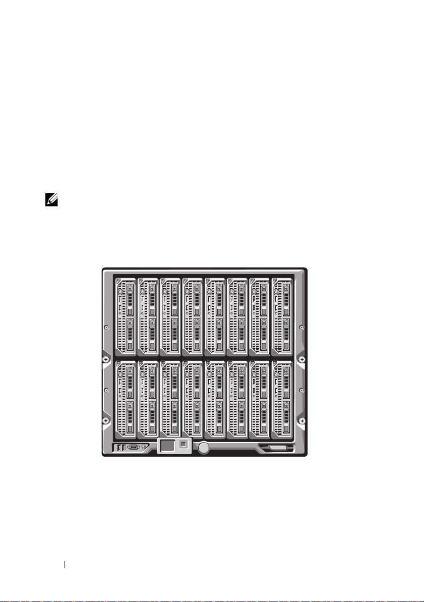
System Overview
12345678
910111213141516
Your system can include up to 16 half-height blades (server modules), eight
full-height blades, or a combination of the two blade types (see Figure 1-1,
Figure 1-2, and Figure 1-3). To function as a system, a blade is inserted into
an enclosure (chassis) that supports power supplies, fan modules, a Chassis
Management Controller (CMC) module, and at least one I/O module for
external network connectivity. The power supplies, fans, CMC, optional
iKVM module, and I/O modules are shared resources of the blades in the
PowerEdge M1000e enclosure.
NOTE: To ensure proper operation and cooling, all bays in the enclosure must be
populated at all times with either a module or with a blank.
Figure 1-1. Blade Numbering – Half-Height Blades
14 About Your System
Page 15
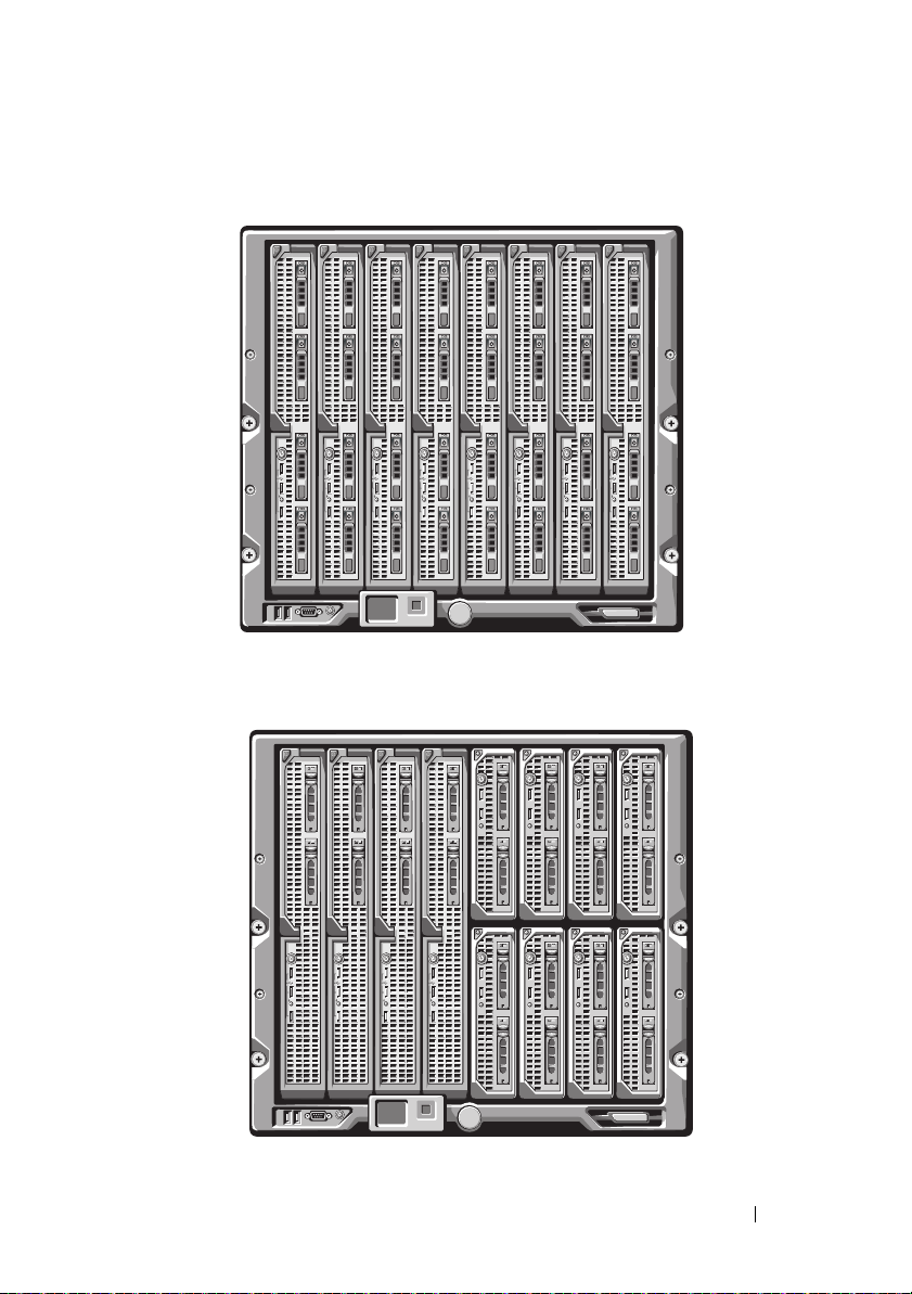
Figure 1-2. Blade Numbering – Full Height Blades
12345678
12345678
13 14 15 16
Figure 1-3. Blade Numbering – Mixed Full-Height and Half-Height Blades
About Your System 15
Page 16
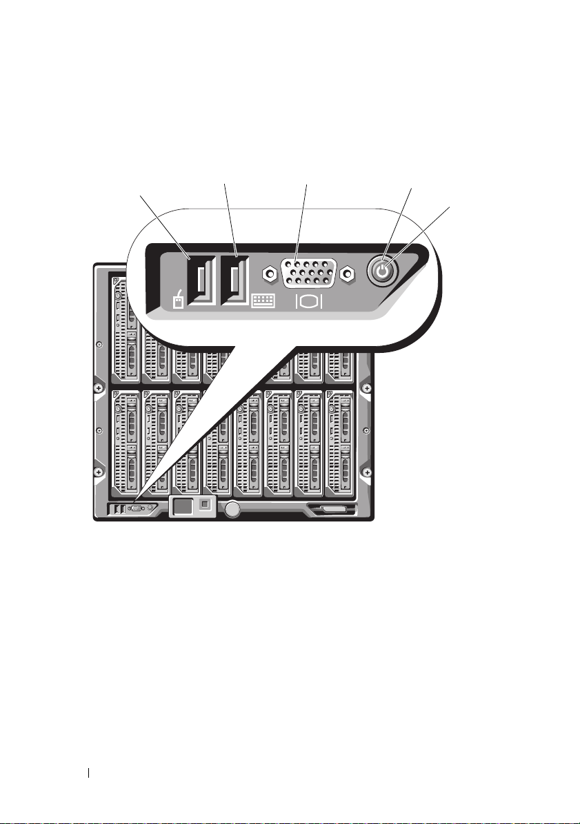
System Control Panel Features
1
2
3
4
5
Figure 1-4. Control Panel Features
1 USB port (mouse only) 2 USB port (keyboard only)
3 video connector 4 system power button
5 power indicator
16 About Your System
Page 17

Table 1-1. Control Panel Features
Item Indicator,
Button, or
Connector
System power
button
System power
indicator
USB ports for
keyboard and
mouse
Video
connector
N/A Turns the system on and off. Press to turn
Off Enclosure does not have power.
Green
N/A Functional if an optional iKVM module is
N/A Functional if an optional iKVM module is
Icon Description
on the system. Press and hold 10 seconds
to turn off the system.
NOTE: The system power button controls
power to all of the blades and I/O modules in
the enclosure.
System power is on.
installed and front panel ports are enabled
(default setting) in the CMC interface.
NOTE: These ports do not support USB
storage devices. Only connect USB storage
devices to the USB ports on the front panel
of the blade.
installed and front panel ports are enabled
(default setting) in the CMC interface.
About Your System 17
Page 18
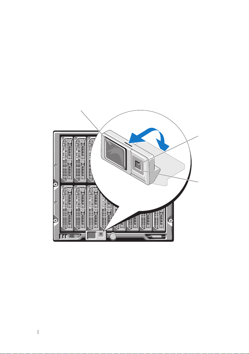
LCD Module
1
3
2
The LCD module provides an initial configuration/deployment wizard, as
well as easy access to infrastructure and blade information, and error
reporting. See Figure 1-5.
Figure 1-5. LCD Display
1 LCD screen 2 selection ("check") button
3 scroll buttons (4)
18 About Your System
Page 19

LCD Module Features
The primary function of the LCD module is to provide real-time information
on the health and status of the modules in the enclosure.
LCD module features include:
• A deployment setup wizard that allows you to configure the CMC
module’s network settings during initial system set up.
• Menus to configure the iDRAC in each blade.
• Status information screens for each blade.
• Status information screens for the modules installed in the back of the
enclosure, including the IO modules, fans, CMC, iKVM, and power
supplies.
• A network summary screen listing the IP addresses of all components in
the system.
• Real time power consumption statistics, including high and low values,
and average power consumption.
• Ambient temperature values.
• AC power information.
• Critical failure alerts and warnings.
Using the LCD Module Menus
Table 1-2. LCD Module Screen Navigation Keys
Keys Action
Left and right arrows Move between screens.
Up arrow or down arrow Move to the previous or next option on a screen.
Center button Select and save an item and move to the next
screen.
About Your System 19
Page 20

Configuration Wizard
The CMC is preset for DHCP. To use a static IP address, you must toggle the
CMC setting from DHCP to a static address by either running the LCD
Configuration Wizard, or by using a management station and CLI
commands. (For more information, see the PowerEdge M1000e Configuration
Guide or CMC documentation.)
NOTE: After you run the configuration wizard, this option is no longer available on
the LCD menus.
1
Choose a language from the options presented in the dialog box.
2
Start the configuration wizard.
3
Configure the CMC network settings for your network environment:
• Network speed
•Duplex mode
• Network mode (DHCP or static)
• Static IP address, subnet mask, and gateway values (if static mode was
selected)
• DNS settings
4
If desired, configure the iDRAC network settings.
See the CMC
NOTE: The configuration wizard automatically configures each blade’s iDRAC
internal network interface if you do not choose to manually configure the
iDRAC settings.
NOTE: You cannot set a static IP address for the iDRAC using the LCD
Configuration Wizard. To set a static IP address, use the CMC Web-based
interface or RACADM.
5
Review the settings on the
User’s Guide
for detailed information about the iDRAC.
Network Summary
screen.
• If the settings are correct, press the center button to close the
configuration wizard and return to the
Main Menu
.
• If the settings are not correct, use the left arrow key to return to the
screen for that setting and correct it.
After you complete the configuration wizard, the CMC is available on your
network.
20 About Your System
Page 21

Main Menu
The Main Menu options include links to the LCD Setup Menu, Server
Menu, and Enclosure Menu.
LCD Setup Menu
You can change the default language and start-up screen for the LCD menu
screens using this menu.
Server Menu
From the Server Menu dialog box, you can highlight each blade in the
enclosure using the arrow keys, and view its status.
• A blade that is powered off or booting is designated by a gray rectangle. An
active blade is indicated by a green rectangle. If a blade has errors, this
condition is indicated by an amber rectangle.
• To select a blade, highlight it and press the center button. A dialog box
displays the iDRAC IP address of the blade and any errors present.
Enclosure Menu
The Enclosure Menu includes options for Module Status, Enclosure Status,
and Network Summary.
•In the
Module Status
dialog box, you can highlight each component in the
enclosure and view its status.
– A module that is powered off or booting is designated by a gray
rectangle. An active module is indicated by a green rectangle. If a
module has errors, it is indicated by an amber rectangle.
– If a module is selected, a dialog box displays the current status of the
module and any errors present.
•In the
Enclosure Status
dialog box, you can view the enclosure status, any
error conditions, and power consumption statistics.
•The
Network
Summary
screen lists the IP addresses for the CMC, the
iDRAC in each blade, and other components in the enclosure.
About Your System 21
Page 22
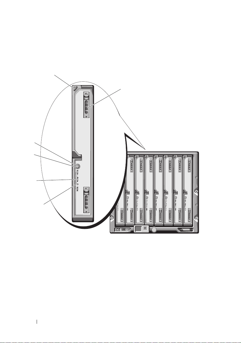
Blade Features
1
2
6
3
5
4
Figure 1-6. Front Panel Features – PowerEdge M915
1 blade handle release button 2 hard drives (2)
3 blade status/identification indicator 4 USB connectors (3)
5 blade power button 6 blade power indicator
22 About Your System
Page 23
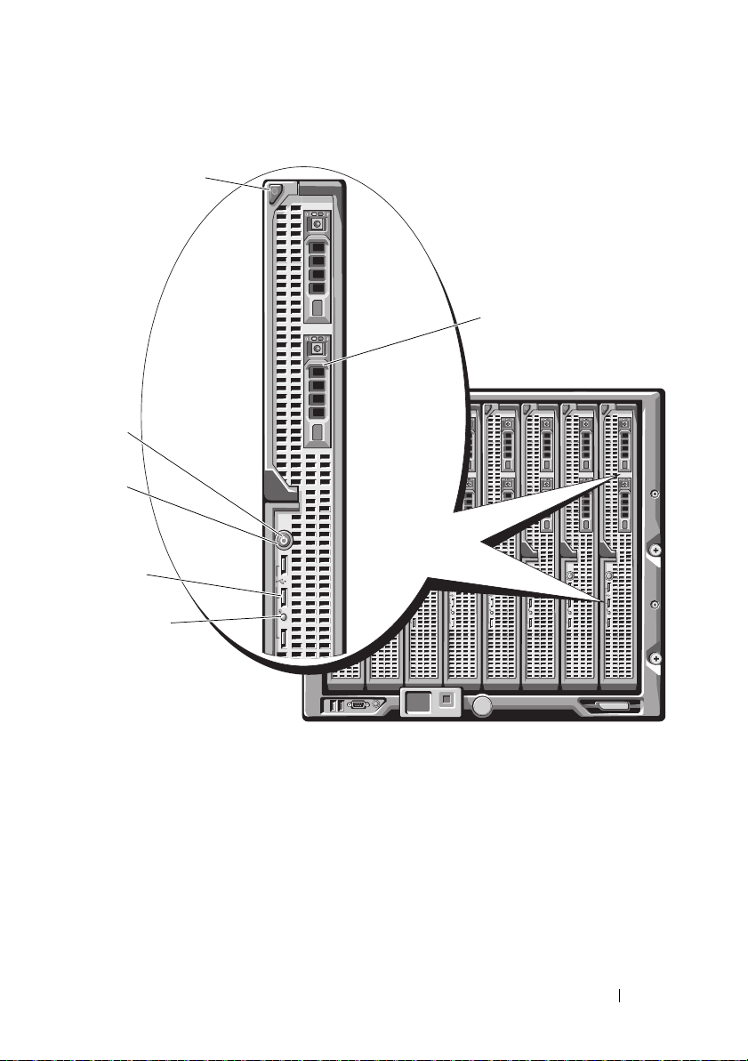
Figure 1-7. Front Panel Features – PowerEdge M910
1
2
4
6
3
5
1 blade handle release button 2 hard drives (2)
3 blade status/identification indicator 4 USB connectors (3)
5 blade power button 6 blade power indicator
About Your System 23
Page 24
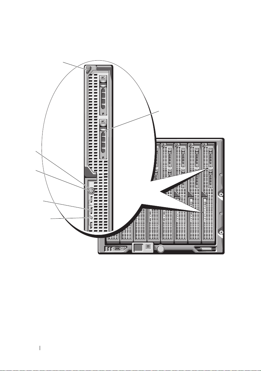
Figure 1-8. Front Panel Features – PowerEdge M905 and M805
1
2
4
6
3
5
1 blade handle release button 2 hard drives (2)
3 blade status/identification indicator 4 USB connectors (3)
5 blade power button 6 blade power indicator
24 About Your System
Page 25
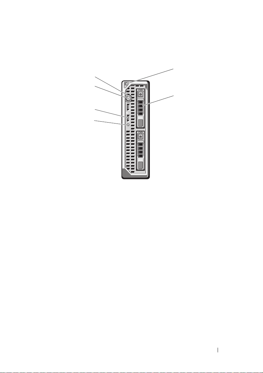
Figure 1-9. Front Panel Features – PowerEdge M710HD
1
2
6
5
4
3
1 blade handle release button 2 hard drives (2)
3 blade status/identification indicator 4 USB connectors (2)
5 blade power button 6 blade power indicator
About Your System 25
Page 26
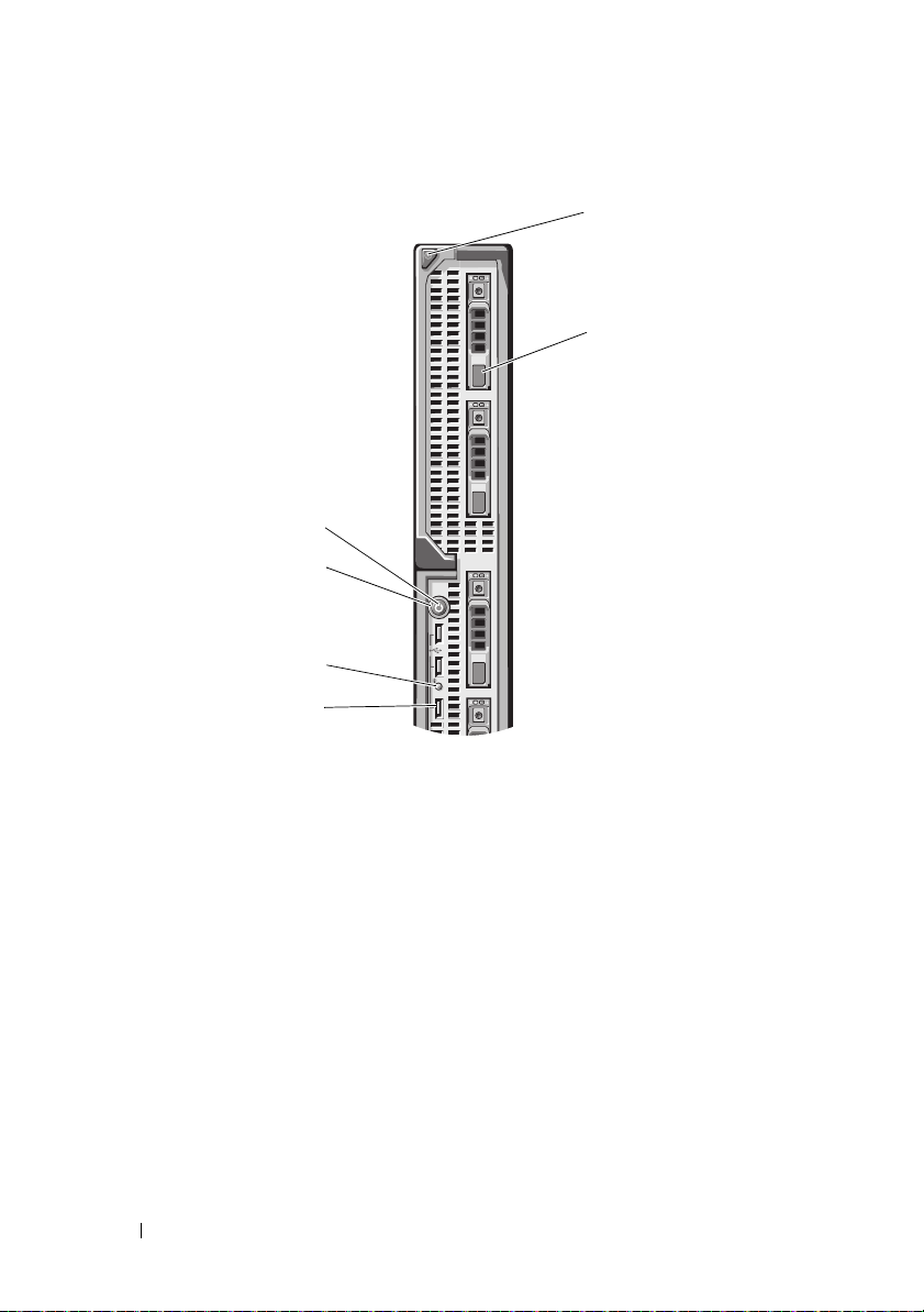
Figure 1-10. Front Panel Features – PowerEdge M710
1
2
4
6
3
5
1 blade handle release button 2 hard drives (4)
3 USB connectors (3) 4 blade status/identification indicator
5 blade power button 6 blade power indicator
26 About Your System
Page 27
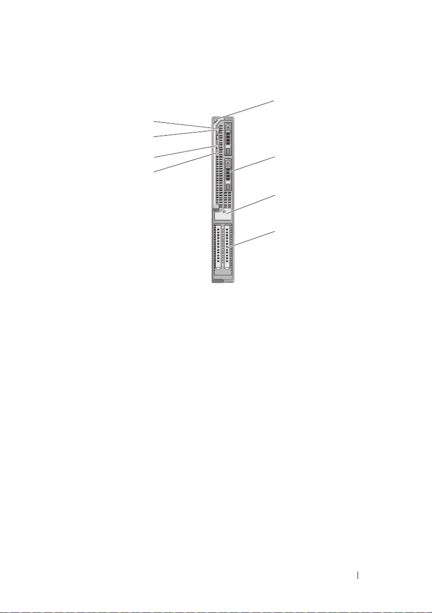
Figure 1-11. Front Panel Features – PowerEdge M610x
1
2
7
5
8
6
3
4
1 blade handle release button 2 hard drive (2)
3 expansion-card filler-bracket
retention latch with captive screw
5 blade status/identification indicator 6 USB connector (2)
7 blade power button 8 blade power indicator
4 expansion-card slot (2)
About Your System 27
Page 28
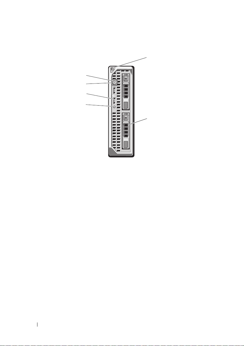
Figure 1-12. Front Panel Features – PowerEdge M610
1
2
4
3
6
5
1 blade handle release button 2 hard drives (2)
3 blade status/identification indicator 4 USB connectors (2)
5 blade power button 6 blade power indicator
28 About Your System
Page 29
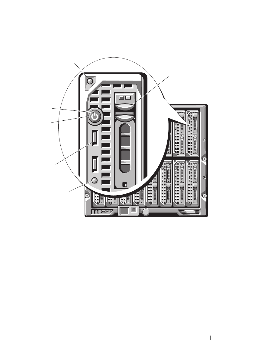
Figure 1-13. Front Panel Features – PowerEdge M605 and M600
1
2
4
5
6
3
1 blade handle release button 2 hard drives (2)
3 blade status/identification indicator 4 USB connectors (2)
5 blade power button 6 blade power indicator
About Your System 29
Page 30

Table 1-3. Blade Control Panel Features
Feature Icon Description
Blade power
indicator
Blade status/
identification
indicator
Blade power
button
USB connector Connects external USB 2.0 devices to the blade.
N/A Turns blade power off and on.
Off – Power is not available to the blade, the blade is
in standby mode, the blade is not turned on, or the
blade is installed incorrectly. For detailed information
on installing a blade, see "Installing a Blade" on
page 158.
Green increasing from low brightness to full
brightness – Blade power on request is pending.
Green on – The blade is turned on.
Off – The blade power is off.
Blue – Normal operating state.
Blue blinking – The blade is being remotely
identified using the CMC.
Amber blinking – Blade has either detected an
internal error, or the installed mezzanine card(s) does
not match the I/O modules installed in the M1000e
enclosure. Check the CMC for an I/O configuration
error message and correct the error.
• If you turn off the blade using the power button
and the blade is running an ACPI-compliant
operating system, the blade can perform an orderly
shutdown before the power is turned off.
• If the blade is not running an ACPI-compliant
operating system, power is turned off immediately
after the power button is pressed.
• Press and hold the button to turn off the blade
immediately.
The blade power button is enabled by default by the
System Setup program.(If the power button option is
disabled, you can only use the power button to turn
on the blade. The blade can then only be shut down
using system management software.)
30 About Your System
Page 31

Using USB Diskette or USB DVD/CD Drives
Each blade has USB ports on the front of the blade which allows you to
connect a USB diskette drive, USB flash drive, USB DVD/CD drive, keyboard,
or mouse. The USB drives can be used to configure the blade.
NOTE: These blades support only Dell-branded USB 2.0 drives. The drive must be
horizontal and level to operate properly. Use the optional external drive storage tray
to support the drive while in use.
NOTE: If the drive must be designated as the boot drive, connect the USB drive,
restart the system, then enter the System Setup Program and set the drive as first in
the boot sequence (see "Using the System Setup Program and UEFI Boot Manager"
on page 137). The USB device is displayed in the boot order setup screen only if it is
attached to the system before you run the System Setup program.
You can also select the boot device by pressing <F11> during system start-up and
selecting a boot device for the current boot sequence.
Hard-Drive Features
• PowerEdge M915 supports two
2.5-inch SAS
or solid-state disk (SSD)
hard drives.
• PowerEdge M910 supports up to two 2.5-inch SAS, SATA, or SSD hard
drives.
• PowerEdge M905 and M805 support one or two hot-swappable
2.5-inch SAS hard drives.
• PowerEdge M710HD supports up to two hot-swappable
2.5-inch SAS or SSD hard drives.
• PowerEdge M710 supports up to four hot-swappable 2.5-inch SAS hard
drives.
• PowerEdge M610, M610x, M600, and M605 support one or two 2.5-inch
SATA hard drives or one or two 2.5-inch SAS hard drives.
NOTE: SAS and SATA hard drives cannot be mixed within a blade.
NOTE: SATA hard drives are not hot swappable with the SATA repeater
daughter card.
NOTE: Hot-swap drive operation is supported if an optional RAID controller
card is installed in the blade.
About Your System 31
Page 32

The hard-disk drives plug into the internal storage backplane inside the blade.
1
2
On blades with a diskless configuration, all hard drive slots must be filled with
hard drive blanks, and the internal storage backplane must still be installed to
maintain proper airflow.
See
Figure 1-14
for information on the hard-drive indicators. Different
patterns are displayed as drive events occur in the system.
NOTE: The blade must have a hard drive or a hard-drive blank installed in each
hard-drive bay.
NOTE: The hard-drive status indicator is only functional for RAID hard drive
configurations. For non-RAID configurations, only the drive-activity indicator is
active. Refer to the RAID controller documentation to service a RAID volume,
rebuild an array, or swap RAID members.
Figure 1-14. Hard-Drive Indicators
1 drive-activity indicator (green) 2 drive-status indicator (green and
amber)
32 About Your System
Page 33

Table 1-4. Hard-Drive Indicators
Condition Drive-Status Indicator Pattern
Identifying drive/preparing
for removal
Drive ready for insertion or
removal
Drive predicted failure Blinks green, amber, and off.
Drive failed Blinks amber four times per second.
Drive rebuilding Blinks green slowly.
Drive online Steady green.
Rebuild halted Blinks green three seconds, amber three seconds, and
Blinks green two times per second
Off
NOTE: The drive status indicator remains off until all
hard drives are initialized after system power is applied.
Drives are not ready for insertion or removal during this
time.
off six seconds.
About Your System 33
Page 34

Back-Panel Features
2
6
1
3
4
5
Figure 1-15. Back-Panel Features
1 fan modules (9) 2 primary CMC module
3 I/O modules (6) 4 optional iKVM module
5 secondary CMC module 6 power supplies (6)
34 About Your System
Page 35

Figure 1-16. Back-Panel Module Bay Numbering
2
1
2
3
4
5
6
7
8
9
123456
A1 B1 C1
C2 B2 A2
CMC 1
CMC 2
iKVM
About Your System 35
Page 36

Power Supply Indicator
2
1
3
NOTE: The power supplies must be connected to a PDU, not directly to an
electrical outlet.
• The power supplies require a 200-240 V power source.
• A 2700 W power supply can be connected to a 110 V AC power source.
Figure 1-17. Power Supply Indicators
1 DC power output indicator 2 power supply fault indicator
3 AC power present indicator
36 About Your System
Page 37

Table 1-5. Power Supply Indicators
1
2
Indicator Icon Description
Power supply
status
Fault indicator Amber indicates a problem with the power supply, which
AC powe r source
present indicator
Green indicates that the power supply is operational and
providing DC power to the system.
can result from either a failed power supply or a failed fan
within the power supply. See "Power Supply Modules."
Green indicates that a valid AC source is connected to the
power supply and is operational.
Fan Module Indicators
Figure 1-18. Fan Module Indicators
1 fan power indicator 2 fan fault indicator
About Your System 37
Page 38

Table 1-6. Fan Indicators
Indicator Indicator
State
Power indicator Green The power supply is connected to an AC power source.
Off AC power not connected.
Fault indicator Amber The fan is in a fault condition.
Off Fan not faulty.
Description
Identifying Midplane Version
The version of the midplane installed in the enclosure is displayed in the
Midplane Revision field under the Summary tab of the CMC Web-based
interface.
You can also view the icons at the back of the enclosure to identify the version
of the midplane installed in the system. Table 1-7 describes the icons at the
back of the enclosure.
Table 1-7. Identifying Midplane Version
Marking Description Midplane Version
I/O module slots A1, A2 1.1
I/O module slots B1, B2, C1,
and C2
1.1
I/O module slots A1, A2 1.0
I/O module slots B1, B2, C1,
and C2
1.0
See Figure 1-19 and Figure 1-20 to locate the midplane identification labels
on the enclosure.
38 About Your System
Page 39

Figure 1-19. Identifying Midplane Version 1.1
1
1 midplane identification label (2)
About Your System 39
Page 40

Figure 1-20. Identifying Midplane Version 1.0
1
1 midplane identification label (2)
40 About Your System
Page 41

iKVM Module
The optional Avocent iKVM analogue switch module includes the following
features:
• Local iKVM access can be remotely disabled on a per blade basis, using the
blade’s iDRAC interface (access is enabled by default).
NOTE: By default (enabled), a console session to a given blade is available to
both the iDRAC interface and iKVM (users connected to a blade's console
using iDRAC and the iKVM sees the same video and is able to type
commands). If this sharing is not desired, this can be disabled using the iDRAC
console interface.
• The following connectors:
– One VGA connector. The iKVM supports a video display resolution
range from 640×480 at 60 Hz up to 1280×1024×65,000 colors
(noninterlaced) at 75 Hz.
– Two USB ports for keyboard and mouse.
NOTE: The iKVM USB ports do not support storage devices.
– RJ-45 ACI port for tiering with Dell and Avocent analog KVM and
KVM over IP switches with ARI ports.
NOTE: Although the ACI port is an RJ-45 connector and uses Cat5 (or better)
cabling, it is not an Ethernet network interface port. It is only used for
connection to external KVM switches with Analog Rack Interface (ARI) ports,
and does not support native KVM over IP.
• The iKVM can also be accessed from the front of the enclosure, providing
front or back panel KVM functionality, but not at the same time. For
enhanced security, front panel access can be disabled using the CMC’s
interface.
NOTE: Connecting a keyboard, video, and mouse to the enclosure front panel
disables video output to the iKVM back panel port. It does not interrupt iDRAC
video and console redirection.
• You can use the iKVM to access the CMC console directly, using
RACADM or using the Web-based interface. For more information, see
"Using the iKVM Module" in the CMC
User’s Guide.
Figure 1-21 shows the external features of the iKVM switch module.
About Your System 41
Page 42

Figure 1-21. Avocent iKVM Switch Module
2
34
1
5
1 identification indicator 2 status indicator
3 ACI port for tiering connection only
CAUTION: Do not connect the ACI port to
a LAN device such as a network hub.
Doing so may result in equipment damage.
5 video connector
4 USB connectors (2) for keyboard
and mouse
Table 1-8. Avocent Analog iKVM Switch Module Features
Feature Indicator Pattern Description
Power
indicator
Status/
identification
indicator
42 About Your System
Off iKVM switch does not have power.
Green iKVM switch has power.
Green flashing Firmware upgrade in progress
Blue blinking iKVM module is being identified.
Amber flashing System fault or error condition.
Page 43

Table 1-8. Avocent Analog iKVM Switch Module Features
Feature Indicator Pattern Description
USB
connectors
Video
connector
ACI port Allows connection of one or more servers to a
Link indicator Off The ACI is not connected to the external switch.
Green The ACI is connected to the external switch.
Activity
indicator
Off Data is not being sent or received.
Amber blinking Data is being sent or received.
Allows a keyboard and mouse to be connected to
the system.
Allows a monitor to be connected to the system.
Dell console switch with an Analog Rack
Interface (ARI) port, such as an external digital
or analog switch.
About Your System 43
Page 44

Tiering the Avocent iKVM Switch From an Analog KVM Switch
The Avocent iKVM switch can be tiered from analog KVM switches such as
the Dell 2160AS and 180AS, as well as many Avocent analog KVM switches.
Many switches may be tiered without the need for a Server Interface Pod
(SIP) (see Table 1-9).
Table 1-9. Cabling Requirements for External Analog KVM Switches
Switch Tiering Cabling Requirements
Dell PowerConnect 180AS, 2160AS
Avocent Autoview 1400, 1500, 2000,
2020, 2030, Ax000R
Avocent Autoview 200, 400, 416, 424
Avocent Outlook 140ES, 180ES,
160ES
Before connecting the iKVM switch to a supported analog switch, you must
set the iKVM switch to display in slot order, and set the Screen Delay Time to
1 or more seconds:
1
Press <Print Screen> to launch the iKVM Switch OSCAR.
The OSCAR dialog box appears on the monitor connected to the iKVM.
2
Click
SetupMenu
3
Select
Slot
to display servers numerically by slot number.
4
Enter a screen delay time of at least 1 second.
5
Click OK.
. The
Setting the Screen Delay Time to 1 second allows you to soft switch to a
server without launching OSCAR.
Seamless tiering using ACI port and Cat 5
cable
Dell USB SIP required with Cat 5 cable
Menu
dialog box appears.
NOTE: Soft switching allows you to switch servers using a hot key sequence. You
can soft switch to a server by pressing <Print Screen> and then typing the first few
characters of its name or number. If you have a Delay Time set and you press the
key sequences before that time has elapsed, OSCAR does not display.
44 About Your System
Page 45

To configure the analog switch:
1
Press <Print Screen> to open the OSCAR
2
Click
Setup DevicesDevice Modify
3
Select the 16-port option to match the number of blades in your system.
4
Click OK to exit OSCAR.
5
Press <Print Screen> to verify that the settings have taken effect. The slot
.
Main
dialog box.
number of the blade to which the iKVM switch is now attached should be
expanded to display each of the slot locations of the blades in the system.
For instance, if the iKVM switch is attached to slot 1, it would now be
displayed as 01-01 to 01-16.
To connect the Avocent iKVM switch to a supported analog switch:
1
If the switch does not require a SIP to connect to the iKVM (see Table 1-9)
connect a Cat5 (or newer) cable to the RJ-45 ACI port on the iKVM
module. See Figure 1-21.
Connect the other end of this cable to the ARI port on the external switch.
,
If the analog switch requires a USB SIP (see Table 1-9)
, connect a USB SIP
to the iKVM, then connect a Cat5 (or newer) cable to the SIP. Connect the
other end of this cable to the ARI port on the external switch.
2
Connect both the analog switch and the system to an appropriate power
source.
3
Turn on the system.
4
Tu r n o n t he
NOTE: If the external analog switch is turned on before the system, it may result in
only one blade displaying in the analog switch OSCAR, instead of 16. If this behavior
occurs, shut down and restart the switch so that the entire complement of blades is
recognized.
NOTE: In addition to the steps outlined above, some external analog switches may
require you to perform additional steps to ensure that the iKVM switch blades
appear in the external analog switch OSCAR. See the external analog switch
documentation for more information.
external
analog switch.
About Your System 45
Page 46

Tiering the Avocent iKVM Switch From a Digital KVM Switch
The iKVM switch may also be tiered from a digital KVM switch such as the
Dell 2161DS or 4161DS, or a supported Avocent digital KVM switch. Many
switches may be tiered without the need for a SIP (see Table 1-10).
Table 1-10. Cabling Requirements for External Digital KVM Switches
Switch Tiering Requirements
Dell PowerConnect 2161DS, 4161DS
Avocent DSR 800, x16x, x010, x031,
x030, x035,102x (except 1024)
Avocent DSR 1024 Dell USB SIP required with Cat 5 cable
To tier the iKVM switch module from a Dell 2161DS, 180AS, or 2160AS
console switch:
•
If the switch does not require a SIP to connect to the iKVM (see
connect a Cat5 (or newer) cable to the RJ-45 ACI port on the iKVM
module. See Figure 1-21.
Connect the other end of this cable to the ARI port on the external switch.
•
If the switch requires a USB SIP (see Table 1-9)
iKVM, then connect a Cat5 (or newer) cable to the SIP. Connect the other
end of this cable to the ARI port on the external switch.
Once the KVM switch is connected, the server modules appear in OSCAR.
Seamless tiering using ACI port and Cat 5
cable
Ta b l e 1 - 1 0),
, connect a USB SIP to the
NOTE: Once the local system is set up, you must also resynchronize the server list
from the Remote Console Switch software in order to see the list of blades. See
Resynchronizing the Server List at the Remote Client Workstation.
46 About Your System
Page 47

Resynchronizing the Server List at the Remote Client Workstation
Once the iKVM switch is connected, the blades appear in OSCAR. You now
need to resynchronize the servers on any remote workstation to ensure that
the blades are available to any remote users connected to the console switch
through the Remote Console Switch software.
NOTE: This procedure only resynchronizes one remote client workstation. With
multiple client workstations, save the resynchronized local database and load it into
the other client workstations to ensure consistency.
To resynchronize the server listing:
1
Click
Resync
in the
Server
category of the Management Panel (MP).
The Resync Wizard launches.
2
Click
Next
.
A warning message displays indicating that the database is updated to
match the current configuration of the console switch. Your current local
database names may be overridden with the switch names. To include
unpowered SIPs in the resynchronization, click to enable the
Offline SIPs
3
Click
A
Polling Remote Console Switch
Next
check-box.
.
message box appears with a progress
Include
bar indicating that the switch information is being retrieved.
4
If no changes were detected in the appliance, a completion dialog box
appears with this information.
If server changes were detected, then the
displayed. Click
Next
to update the database.
Detected Changes
dialog box is
5
If a cascade switch was detected, the
Enter Cascade Switch Information
dialog box appears. Select the type of switch connected to the appliance
from the drop-down list. If the type you are looking for is not available, you
can add it by clicking
6
Click
Next
. The completion dialog box appears.
7
Click
Finish
to exit.
8
Start up the analog switch and the system.
Add
.
About Your System 47
Page 48

CMC Module
4
2
3
1
5
8
9
10
6
7
Figure 1-22. CMC Module Features
1 Ethernet connector Gb1 2 link indicator (2)
3 Ethernet connector STK ("stack") -
used for daisy-chaining CMCs in
separate enclosures
5 DB-9 serial connector for local
configuration
7 primary CMC (CMC 1) 8 amber fault indicator
9 blue status/identification indicator 10 power indicator
4 activity indicator (2)
6 optional secondary CMC (CMC 2)
48 About Your System
Page 49

Table 1-11. CMC Module Features
Indicator Pattern Description
Network
interface
controller link
indicator
Network
interface
controller
activity
indicator
Power indicator Off CMC does not have power.
Status/
identification
indicator
Fault indicator Off The CMC is operating normally.
Serial
connector
Off LAN is not linked.
Green LAN is linked.
Off LAN is not active.
Amber
blinking
Green CMC has power.
Green
blinking
Off This CMC is the standby CMC.
Blue (solid) This CMC is the primary CMC.
Blue
(blinking)
Amber
blinking
None Used for local configuration (115200 baud, No parity,
Indicates that the system CMC and the LAN are
communicating.
Firmware update in progress.
The CMC is being identified by the systems
management software.
A fault has occurred.
8, 1)
The CMC provides multiple systems management functions for your
modular server:
• Enclosure-level real-time automatic power and thermal management.
– The CMC monitors system power requirements and supports the
optional Dynamic Power Supply Engagement mode so that the CMC
can enable or place power supplies in standby dynamically depending
on load and redundancy requirements to improve power efficiency.
– The CMC reports real-time power consumption, which includes
logging high and low points with a time stamp.
About Your System 49
Page 50

– The CMC supports setting an optional enclosure Maximum Power
Limit, which either alerts or takes actions, such as throttling server
modules and/or preventing the power up of new blades to keep the
enclosure under the defined maximum power limit.
– The CMC monitors and automatically controls cooling fans based on
actual ambient and internal temperature measurements.
– The CMC provides comprehensive enclosure inventory and
status/error reporting.
• The CMC provides a mechanism for centralized configuration of the
following:
– The M1000e enclosure’s network and security settings
– Power redundancy and power ceiling settings
– I/O switches and iDRAC network settings
– First boot device on the server blades
– The CMC checks I/O fabric consistency between the I/O modules and
blades and disables components if necessary to protect the system
hardware.
– User access security.
The CMC has two Ethernet ports: Gb1 is used to connect to the external
management network. The connector labeled STK ("stack") allows CMCs in
adjacent enclosures to be daisy-chained. A 24-port Ethernet switch provides
internal communication between the iDRAC on each blade, I/O modules,
optional KVM, and optional second, redundant CMC.
NOTE: The 24-port Ethernet switch is reserved for internal communication
between the iDRAC on the blades to the CMC and the external management
network. If two CMCs are installed, the heartbeat for CMC redundancy is also
present and CMC redundancy is supported over this internal network. This internal
network is outside the data path from host LOMs and the mezzanine cards in the
blades.
At least one CMC must be installed in the primary CMC bay (see
Figure 1-22) for the system to power up. If a second, optional CMC module is
installed, failover protection and hot-plug replacement is available.
See the latest Dell Chassis Management Controller User's Guide at
support.dell.com/manuals for complete instructions on how to set up and
operate the CMC module.
50 About Your System
Page 51

Figure 1-23. CMC Daisy-Chaining
1
2
3
1 management network 2 secondary CMC
3 primary CMC
About Your System 51
Page 52

I/O Connectivity
The M1000e enclosure
combinations of Ethernet, fibre-channel, and Infiniband modules. You can
install up to six hot-swappable I/O modules in the enclosure, including fibrechannel switches, fibre-channel pass-throughs, Infiniband switches, Ethernet
switches, and Ethernet pass-through modules
supports three layers of I/O fabric, selectable between
.
Guidelines for Installing I/O Modules
You must follow these guidelines when populating I/O modules. See
Figure 1-15 for the I/O bay locations.
General I/O Module Configuration Guidelines
• If an I/O module is installed in Fabric B or Fabric C, at least one blade
must have a matching mezzanine card installed to support data flow for
that I/O module.
• If a blade has an optional mezzanine card installed in a Fabric B or Fabric
C card slot, at least one corresponding I/O module must be installed to
support data flow for that fabric.
• Modules may be installed in Fabrics B and C independently (you do not
need to install modules in Fabric B before installing modules in the Fabric
C slots.)
• Slots A1 and A2 only support Ethernet I/O modules. This fabric type is
hard-set to Ethernet for these slots and cannot support Fibre Channel,
Infiniband, or other fabric type modules.
• Fabrics A, B, and C can support Ethernet fabric-type modules.
• To enable switch configuration prior to blade imaging, I/O modules are
allowed to power-up before a blade is inserted in the enclosure.
Fabric A
Fabric A is a redundant Gb Ethernet fabric, supporting I/O module slots A1
and A2. The integrated Ethernet controllers in each blade dictate Fabric A as
an Ethernet-only fabric.
NOTE: Fabric A supports KR (10 Gbps standard) if the midplane version in the
enclosure is 1.1 or later. To identify the midplane version, see "Identifying Midplane
Version" on page 38.
52 About Your System
Page 53

NOTE: Modules designed specifically for Fabric B or Fabric C cannot be installed in
slots A1 or A2, as indicated by the color-coded labeling on the faceplate of each
module.
Fabric B
Fabric B is a 1 to 40 Gb/sec redundant fabric, supporting I/O module slots B1
and B2. Fabric B currently supports 1 Gb or10 Gb Ethernet, DDR/QDR
Infiniband, and 4 Gbps or 8 Gbps Fibre Channel modules. Additional fabric
types may be supported in the future.
NOTE: If the midplane version in the enclosure is 1.1 or later, Fabric B supports up
to 16 Gbps Fibre Channel, Infiniband FDR (14 Gbps standard), and KR (10 Gbps
standard). To identify the midplane version, see "Identifying Midplane Version" on
page 38.
To communicate with an I/O module in the Fabric B slots, a blade must have
a matching mezzanine card installed in a Fabric B mezzanine card location.
Modules designed for Fabric A may also be installed in the Fabric B slots.
Fabric C
Fabric C is a 1 to 40 Gb/sec redundant fabric, supporting I/O module slots C1
and C2. Fabric C currently supports 1 Gb or10 Gb Ethernet, DDR/QDR
Infiniband, and 4 Gbps or 8 Gbps Fibre Channel modules. Additional fabric
types may be supported in the future.
NOTE: If the midplane version in the enclosure is 1.1 or later, Fabric C supports up
to 16 Gbps Fibre Channel, Infiniband FDR (14 Gbps standard), and KR (10 Gbps
standard). To identify the midplane version, see "Identifying Midplane Version" on
page 38.
To communicate with an I/O module in the Fabric C slots, a blade must have
a matching mezzanine card installed in a Fabric C mezzanine card location.
Modules designed for Fabric A may also be installed in the Fabric C slots.
Port Auto-Disablement in Quad-Port Network Daughter Card (PowerEdge M710HD Only)
Systems installed with quad-port Network Daughter Card support Port AutoDisablement feature. This feature disables the third (NIC3) and fourth
(NIC4) ports of a quad-port Network Daughter Card during system boot, if
the corresponding IO module installed in the chassis Fabric A slots do not
About Your System 53
Page 54

support quad-port mapping. This behavior is limited to Fabric A slots only
and is automatically enabled or disabled depending on the type of IO module
installed.
NOTE: A quad-port Network Daughter Card must be used with a 48-port switch
module (32 internal ports) for all the ports to be active.
NOTE: LOM firmware updates are applied only to the enabled ports on a quad-port
network daughter card.
Table 1-12 provides an overview of the configurations that enable/disable the
NIC3 and NIC4 ports of a quad-port Network Daughter Card.
Table 1-12. Port Auto-Disablement Decision Table
IOM Slot A1 IOM Slot A2 NIC3 and NIC4
(Enabled/Disabled)
Empty Empty Enabled Inactive
Empty Dual Port Disabled Active
Empty Quad or Greater
Port
Dual Port Empty Disabled Active
Dual Port Dual Port Disabled Active
Dual Port Quad or Greater
Port
Quad or Greater
Port
Quad or Greater
Port
Quad or Greater
Port
Empty Enabled Inactive
Dual Port Enabled Inactive
Quad or Greater
Port
Enabled Inactive
Enabled Inactive
Enabled Inactive
Port AutoDisablement
54 About Your System
Page 55

Mezzanine Cards
PowerEdge M610x Only
PowerEdge M610x supports two mezzanine cards. Mezzanine cards can be
installed in both the slots on the midplane interface card.
NOTE: PowerEdge M610x is a full-height blade but supports only two mezzanine
cards in the expansion bay. The two mezzanine slots on the M610x system board
(MEZZ2_FAB_B and MEZZ1_FAB_C) are reserved for the mezzanine interface card.
See "Mezzanine Interface Card (PowerEdge M610x Only)" on page 215.
Full-Height Blades
Full-height blades support four mezzanine cards:
• Slot Mezz1_Fabric_C and slot Mezz3_Fabric_C support Fabric C. They
must match the fabric type of the I/O modules installed in I/O module
slots C1 and C2.
• Slot Mezz2_Fabric_B and slot Mezz4_Fabric_B support Fabric B. They
must match the fabric type of the I/O modules installed in I/O module
slots B1 and B2.
Half-Height Blades
Half-height blades support two mezzanine cards:
• Mezzanine card slot C supports Fabric C. This card must match the fabric
type of I/O modules installed in I/O module slots C1 and C2.
• Mezzanine card slot B supports Fabric B. This card must match the fabric
type of I/O modules installed in I/O module slots B1 and B2.
See "I/O Module Mezzanine Cards" on page 217 for more information on
mezzanine cards.
Table 1-13 shows various supported combinations of mezzanine cards and I/O
modules.
About Your System 55
Page 56

Table 1-13. Supported I/O Module Configurations
Fabric A Fabric B
Mezzanine
Card
Standard
Integrated
LOM
Standard
Integrated
LOM
Standard
Integrated
LOM
Standard
Integrated
LOM
Standard
Integrated
LOM
none none Ethernet
Ethernet
mezzanine
card
none Infiniband
Ethernet
mezzanine
card
Fibre
Channel
mezzanine
card
Fabric C
Mezzanine
Card
none Ethernet
mezzanine
card
Ethernet
mezzanine
card
Infiniband
mezzanine
card
I/O Bay A1, A2I/O Bay B1, B2I/O Bay C1,
switch
module or
passthrough
module
switch
module or
passthrough
module
Ethernet
switch
module or
passthrough
module
Ethernet
switch
module or
passthrough
module
Ethernet
switch
module or
passthrough
module
C2
none none
Ethernet
switch
module or
passthrough
module
none Infiniband
Ethernet
switch
module or
passthrough
module
Fibre
Channel
switch or
passthrough
module
none
switch
module
Ethernet
switch
module or
passthrough
module
Infiniband
switch
module
56 About Your System
Page 57

Table 1-13. Supported I/O Module Configurations
(continued)
Fabric A Fabric B
Mezzanine
Card
Standard
Integrated
LOM
Standard
Integrated
LOM
Standard
Integrated
LOM
Standard
Integrated
LOM
Standard
Integrated
LOM
none Fibre
Fibre
Channel
mezzanine
card
Ethernet
mezzanine
card
Infiniband
mezzanine
card
Infiniband
mezzanine
card
Fabric C
Mezzanine
Card
Channel
mezzanine
card
Fibre
Channel
mezzanine
card
Fibre
Channel
mezzanine
card
Infiniband
mezzanine
card
Ethernet
mezzanine
card
I/O Bay A1, A2I/O Bay B1, B2I/O Bay C1,
C2
Ethernet
switch
module or
passthrough
module
Ethernet
switch
module or
passthrough
module
Ethernet
switch
module or
passthrough
module
Ethernet
switch
module or
passthrough
module
Ethernet
switch
module or
passthrough
module
none Fibre
Channel
switch
module or
passthrough
module
Fibre
Channel
switch or
passthrough
module
Ethernet
switch
module or
passthrough
module
Infiniband
switch
module
Infiniband
switch
module
Fibre
Channel
switch or
passthrough
module
Fibre
Channel
switch or
passthrough
module
Infiniband
switch
module
Ethernet
switch
module or
passthrough
module
About Your System 57
Page 58

Table 1-13. Supported I/O Module Configurations
(continued)
Fabric A Fabric B
Mezzanine
Card
Standard
Integrated
LOM
Fibre
Channel
mezzanine
card
Fabric C
Mezzanine
Card
Ethernet
mezzanine
card
I/O Bay A1, A2I/O Bay B1, B2I/O Bay C1,
C2
Ethernet
switch
module or
passthrough
module
Fibre
Channel
switch or
passthrough
module
Ethernet
switch
module or
passthrough
module
I/O Module Port Mapping
The LOM and optional mezzanine cards are mapped to the I/O module ports
based on the following rules.
NOTE: The I/O port mappings in the following sections are applicable only to the
I/O Pass-Through Modules.
Full-Height Blades
Standard LOM (Dual-Port) Mapping
Each LOM has two port connections. For a full-height blade in bay n:
• Integrated LOM1, connection 1 connects to I/O module A1, portn.
Integrated LOM1, connection 2 connects to I/O module A2, port
• Integrated LOM2, connection 1 connects to I/O module A1, port
Integrated LOM2, connection 2 connects to I/O module A2, port
For example, in a full-height blade in slot 5, integrated LOM1 connection 1
connects
module A2 port 5. LOM2 connection 1
and LOM2 connection 2
to
I/O module A1, port
5 and LOM1 connection 2
connects
connects
to I/O module A2, port 13.
connects
to
I/O module A1, port
n
.
n+8
n+8
to I/O
13
.
.
NOTE: Even though PowerEdge M610x is a full-height blade system, only one
network controller (LOM1) is available.
For PowerEdge M610x blade in bay n:
• The integrated NIC connects to I/O module A1, port n and I/O module
A2, port n
58 About Your System
Page 59

Dual-Port Mezzanine Cards
Each mezzanine card has two port connections. For a full-height blade in bay
n:
• Mezzanine card 1, connection 1 connects to I/O module C1, port n.
Mezzanine card 1, connection 2 connects to I/O module C2, port
• Mezzanine card 2, connection 1 connects to I/O module B1, port
Mezzanine card 2, connection 2 connects to I/O module B2 port
• Mezzanine card 3, connection 1 connects to I/O module C1, port
Mezzanine card 3, connection 2 connects to I/O module C2 port
• Mezzanine card 4, connection 1 connects to I/O module B1, port
Mezzanine card 4, connection 2 connects to I/O module B2 port
For example, in a full-height blade mezzanine card 3, connection 1
to I/O module C1, port
module C2 port
13
and
Mezzanine card 3, connection 2
13. Table 1-15 shows the port number assignments for the
n
.
n
.
n.
n+8
.
n+8.
n+8
.
n+8.
connects
connects to I/O
eight possible full height blade locations.
NOTE: Even though PowerEdge M610x is a full blade system, only two mezzanine
card slots (MEZZ1_Fab_C1 and MEZZ2_FAB_B1) in the expansion bay are available
for use. The other two slots on the system board (MEZZ1_FAB_C and
MEZZ2_FAB_B) are occupied by the mezzanine interface card which provides
connectivity between the PCIe expansion-card riser and the system board.
For PowerEdge M610x in bay n:
• Mezzanine card B (in the expansion bay) connects to I/O module B1, port
n+8 and I/O module B2, port n+8.
• Mezzanine card C (in the expansion bay) connects to I/O module C1, port
n+8 and I/O module C2, port n+8.
Table 1-14. Example of I/O Module Port Assignments - PowerEdge M610x in Slot 2
Blade 2 I/O Module
A1 B1 C1 C2 B2 A2
Mezzanine
Card C
Mezzanine
Card B
Port 10 Port 10
Port 10 Port 10
About Your System 59
Page 60

Figure 1-24. Example of PowerEdge M610x Port Mapping of – Blade 2
60 About Your System
Page 61

Table 1-15. I/O Module Port Assignments - Full-Height Blades (not applicable for
PowerEdge M610x)
Blade 1 I/O Module
B1 C1 C2 B2
Mezz1_Fab_C Port 1 Port 1
Mezz2_Fab_B Port 1 Port 1
Mezz3_Fab_C Port 9 Port 9
Mezz4_Fab_B Port 9 Port 9
Blade 2 I/O Module
B1 C1 C2 B2
Mezz1_Fab_C Port 2 Port 2
Mezz2_Fab_B Port 2 Port 2
Mezz3_Fab_C Port 10 Port 10
Mezz4_Fab_B Port 10 Port 10
Blade 3 I/O Module
B1C1C2B2
Mezz1_Fab_C Port 3 Port 3
Mezz2_Fab_B Port 3 Port 3
Mezz3_Fab_C Port 11 Port 11
Mezz4_Fab_B Port 11 Port 11
About Your System 61
Page 62

Blade 4 I/O Module
B1 C1 C2 B2
Mezz1_Fab_C Port 4 Port 4
Mezz2_Fab_B Port 4 Port 4
Mezz3_Fab_C Port 12 Port 12
Mezz4_Fab_B Port 12 Port 12
Blade 5 I/O Module
B1 C1 C2 B2
Mezz1_Fab_C Port 5 Port 5
Mezz2_Fab_B Port 5 Port 5
Mezz3_Fab_C Port 13 Port 13
Mezz4_Fab_B Port 13 Port 13
Blade 6 I/O Module
B1 C1 C2 B2
Mezz1_Fab_C Port 6 Port 6
Mezz2_Fab_B Port 6 Port 6
Mezz3_Fab_C Port 14 Port 14
Mezz4_Fab_B Port 14 Port 14
Blade 7 I/O Module
B1 C1 C2 B2
Mezz1_Fab_C Port 7 Port 7
Mezz2_Fab_B Port 7 Port 7
Mezz3_Fab_C Port 15 Port 15
Mezz4_Fab_B Port 15 Port 15
62 About Your System
Page 63

Blade 8 I/O Module V
B1 C1 C2 B2
Mezz1_Fab_C Port 8 Port 8
Mezz2_Fab_B Port 8 Port 8
Mezz3_Fab_C Port 16 Port 16
Mezz4_Fab_B Port 16 Port 16
Figure 1-25 shows the port connections for a full-height blade in bay 3 with
four mezzanine cards.
Figure 1-25. Example of Full-Height Blade Port Mapping – Blade 3 (not applicable for
PowerEdge M610x)
About Your System 63
Page 64

Quad-Port Mezzanine Cards
Table 1-16 illustrates the I/O module port mapping for full-height blades with
quad-port mezzanine cards.
NOTE: For a detailed mapping of each PowerEdge system, see the document
Quadport Capable Hardware for the M1000e Modular Chassis on
support.dell.com/manuals.
Table 1-16. I/O Module Port Assignments—Full-Height Blades (not applicable for
PowerEdge M610x)
n
and Blade (n + 8) I/O Module
Blade
NOTE: n denotes a variable
value from 1 to 8.
Mezz_FAB_B_Blade n_Port1 Port n
Mezz_FAB_B_Blade n_Port2 Port n
Mezz_FAB_B_Blade n_Port3 Port
Mezz_FAB_B_Blade n_Port4 Port
Mezz_FAB_C_Blade n_Port1 Port n
Mezz_FAB_C_Blade n_Port2 Port n
Mezz_FAB_C_Blade n_Port3 Port
Mezz_FAB_C_Blade n_Port4 Port
Mezz_FAB_B_Blade
n+8_Port1
Mezz_FAB_B_Blade
n+8_Port2
Mezz_FAB_B_Blade
n+8_Port3
Mezz_FAB_B_Blade
n+8_Port4
Mezz_FAB_C_Blade
n+8_Port1
B1 C1 C2 B2
(n+16)
(n+16)
(n+16)
(n+16)
Port
(n+8)
Port
(n+8)
Port
(n+24)
Port
(n+24)
Port
(n+8)
64 About Your System
Page 65

Table 1-16. I/O Module Port Assignments—Full-Height Blades
applicable for PowerEdge M610x)
n
and Blade (n + 8) I/O Module
Blade
NOTE: n denotes a variable
value from 1 to 8.
Mezz_FAB_C_Blade
n+8_Port2
Mezz_FAB_C_Blade
n+8_Port3
Mezz_FAB_C_Blade
n+8_Port4
NOTE: Even though PowerEdge M610x is a full blade system, only two mezzanine
card slots (MEZZ1_Fab_C1 and MEZZ2_FAB_B1) in the expansion bay are available
for use. The other two slots on the system board (MEZZ1_FAB_C and
MEZZ2_FAB_B) are occupied by the mezzanine interface card which provides
connectivity between the PCIe expansion-card riser and the system board.
B1 C1 C2 B2
Port
(n+8)
Port
(n+24)
Port
(n+24)
(continued)
(not
Table 1-17 illustrates the I/O module port mapping for PowerEdge M610x
in bay n.
Table 1-17. Example of I/O Module Port Assignments - PowerEdge M610x Blade 1
Blade 1 I/O Module
A1 B1 C1 C2 B2 A2
Mezzanine
Card C (port 1
and port 2)
Mezzanine
Card C (port
3and port 4)
Mezzanine
Card B (port 1
and port 2)
Mezzanine
Card B (port 1
and port 2)
Port 9 Port 9
Port 25 Port 25
Port 9 Port 9
Port 25 Port 25
About Your System 65
Page 66

Half-Height Blades
Standard LOM (Dual-Port) and Network Daughter Card (Quad-Port) Mapping
Each standard LOM has two port connections. For a half-height blade
in bay n:
• Integrated LOM, connection 1 connects to I/O module A1, portn.
Integrated LOM, connection 2 connects to I/O module A2, port
n
.
Half-height blades with Network Daughter Card (PowerEdge M710HD)
hosts two network controllers (LOM1 and LOM2), each with two port
connections. For a half-height blade in bay n:
• LOM1, connection 1 connects to I/O module A1, portn.
LOM1, connection 2 connects to I/O module A2, port
• LOM2, connection 1 connects to I/O module A1, port
LOM2, connection 2 connects to I/O module A2, port
NOTE: If the I/O modules A1 and A2 are not quad-port capable, then the LOM2
ports (NIC3 and NIC4) gets disabled during system boot. For more information, see
"Port Auto-Disablement in Quad-Port Network Daughter Card (PowerEdge M710HD
Only)" on page 53.
n
.
n+16
n+16
.
.
For example, in a half-height blade in slot 5, integrated LOM1 connection 1
connects
module A2, port 5. LOM2 connection 1
and LOM2 connection 2
to
I/O module A1, port
5 and LOM1 connection 2
connects
connects
to I/O module A2, port 21.
connects
to
I/O module A1, port
to I/O
21
Dual-Port Mezzanine Cards
For a half-height blade in bay n:
• The integrated NIC connects to I/O module A1, port n and I/O module
A2, port
n.
• Mezzanine card B connects to I/O module B1, port n and I/O module B2,
port
n.
• Mezzanine card C connects to I/O module C1, port n and I/O module C2,
port
n.
For example, in a blade in slot 12, the integrated NIC
A1, port
12 and I/O module A2, port 12.
connects
to
I/O module
66 About Your System
Page 67

Table 1-18. Example of I/O Module Port Assignments - Half-Height Blade 1
Blade 1 I/O Module
A1 B1 C1 C2 B2 A2
Integrated NIC Port 1 Port 1
Mezzanine
Card C
Mezzanine
Card B
Port 1 Port 1
Port 1 Port 1
Figure 1-26 shows the port connections for a half-height blade in bay 1 with
two mezzanine cards.
About Your System 67
Page 68

Figure 1-26. Example of Half-Height Blade Port Mapping
68 About Your System
Page 69

Quad-Port Mezzanine Cards
Table 1-19 illustrates the I/O module port mapping for a half-height blade
with the quad-port mezzanine card. In the following table, n denotes a
variable value from 1 to 16.
NOTE: For a detailed mapping of each PowerEdge system, see the document
Quadport Capable Hardware For the M1000e Modular Chassis on
support.dell.com/manuals.
Table 1-19. I/O Module Port Assignments—Half-Height Blades
n
Blade
A1 B1 C1 C2 B2 A2
Integrated LOM1 Port n
Integrated LOM2 Port n
Mezz_FAB_B_Blade n_Port1 Port n
Mezz_FAB_B_Blade n_Port2 Port n
Mezz_FAB_B_Blade n_Port3 Port
(n+16)
Mezz_FAB_B_Blade n_Port4 Port
Mezz_FAB_C_Blade n_Port1 Port n
Mezz_FAB_C_Blade n_Port2 Port n
Mezz_FAB_C_Blade n_Port3 Port
Mezz_FAB_C_Blade n_Port4 Port
I/O Module
(n+16)
(n+16)
(n+16)
Dell PowerConnect-KR 8024-k Switch
The PowerConnect M8024-k switch provides 16 internal 10 GbE ports, four
external 10 GbE SFP+ ports, and one 10 GbE expansion slot for 10 GbE
external uplinks. The expansion slot on the front panel can support:
• A 10 Gb Ethernet module with four optical SFP+ connectors
• A 10 Gb Ethernet module with three copper CX4 uplinks
About Your System 69
Page 70

• A 10 Gb Ethernet module with two copper 10GBASE-T uplinks
1
2
3
4
5
This module is hot-swappable and may be installed in Fabric A, B, or C.
Figure 1-27. Dell PowerConnect-KR 8024-k Switch
1 SFP+ ports (4) 2 console management connector
3 power indicator 4 status/identification indicator
5 expansion slot
70 About Your System
Page 71

Dell M8428-k 10 Gb Converged Network Switch
The Dell M8428-k 10 Gb Converged Network switch module supports FCoE
protocols and allows Fibre Channel traffic to travel over 10 Gbps Converged
Enhanced Ethernet (DCB) networks. This module consists of:
• Four 8 Gbps external autosensing Fibre Channel ports
• Eight 10 Gb Enhanced Ethernet (DCB) optical SFP+ port connectors
• Sixteen internal 10 Gb Enhanced Ethernet (DCB/FCoE) ports that link to
the blades in the enclosure
• One serial port with an RJ-45 connector.
This Fibre Channel switch may be installed in either Fabric B or Fabric C.
NOTE: This switch module includes Short Wave Small Form Factor Pluggable (SFP)
optical transceivers in the Fibre Channel ports. To ensure proper Fibre Channel
functionality, use only SFPs provided with this module.
About Your System 71
Page 72

Figure 1-28. Dell M8428-k 10 Gb Converged Network Switch
7
1
2
3
4
5
6
1 LED status indicators (12) 2 serial port (RJ-45 connector)
3 module status indicator 4 diagnostic status indicator
5 power indicator 6 8 Gb Fibre Channel ports
7 10 GbEE ports (ports 17–24)
(ports 25–27 and port 0)
72 About Your System
Page 73

Mellanox M3601Q QDR Infiniband Switch I/O Module
2
1
4
5
3
The Mellanox M3601 Infiniband switch I/O module includes 32 4x QDR
Infiniband ports. Of these, 16 ports are external uplink ports, while 16
internal ports provide connectivity to the blades in the enclosure. This
module occupies two I/O module slots. The M3610Q module plugs into I/O
module slot C1, but occupies both slots B1 and C1.
Figure 1-29. Mellanox M3601Q Infiniband Switch Module
1 Infiniband ports (16) 2 port link status indicators (16)
3 port activity indicators (16) 4 module diagnostic power indicator
5 module status indicator
About Your System 73
Page 74

Mellanox M2401G Infiniband Switch I/O Module
4
1
5
2
3
The Mellanox M2401G Infiniband switch I/O module includes 24 4x DDR
Infiniband ports. Eight ports are external uplink ports, while 16 internal ports
provide connectivity to the blades in the enclosure.
Figure 1-30. Mellanox M2401G Infiniband Switch Module
1 Infiniband ports (8) 2 port link status indicators (8)
3 port activity indicators (8) 4 diagnostic power indicator
5 status indicator
74 About Your System
Page 75

Table 1-20. Mellanox M2401G Infiniband Switch Indicators
Indicator Pattern Description
Link indicator Green, on Physical link established
Green, off No physical link present
Activity indicator Amber, on Valid logical link to Infiniband network
established
Amber, blinking Data transfer is in progress
Amber, off No logical link to Infiniband network
Cisco SFS M7000e Infiniband Switch Module
The Cisco SFS M7000e Infiniband switch module includes 24 4x DDR
Infiniband ports. Eight ports are external uplink ports, and 16 internal ports
provide connectivity to the blades in the enclosure. This switch module is
hot-swappable, and may be installed in Fabric B or Fabric C. For general
information on installing this module, see "I/O Modules" on page 296.
About Your System 75
Page 76

Figure 1-31. Cisco SFS M7000e Infiniband Switch Module Features
3
1
4
2
1 Infiniband ports (8) 2 port status indicator (8)
3 diagnostic status indicator 4 power indicator
Table 1-21. Cisco SFS M7000e Infiniband Switch Indicators
Indicator Type Pattern Description
Infiniband
port status
indicator
Off Link error or Subnet Manager not operating
Green flickering I/O activity on port
Green on Link established
76 About Your System
Page 77

Table 1-21. Cisco SFS M7000e Infiniband Switch Indicators
Indicator Type Pattern Description
Module status
indicator
Module power
indicator
Off Switch is not ready
Blue on Switch operating normally
Amber on or
blinking
Off Power to the module is off
Green Module has power
Fault condition in module
(continued)
Cisco Ethernet Switch
Your system supports three Cisco Catalyst Blade Switch (CBS) versions:
• The Cisco 3130G-S switch includes four
ports and two Stackwise Plus ports.
• The Cisco CBS 3130X-S switch includes four
uplink ports,
two 10 Gb uplink ports,
• The Cisco CBS 3032 switch includes four
uplink ports.
The two option bays support the following module options:
• Cisco X2 10 Gb transceiver modules (CBS 3130X-S only)
• Cisco TwinGig converter modules
All three switches include a RJ-45 console connector for switch management.
Sixteen internal Gb Ethernet connectors link to the blades in the enclosure.
See Figure 1-32.
For additional information about the Cisco CBS Ethernet switch modules,
see the documentation that shipped with the module. For general
information on installing this module, see "I/O Modules" on page 296.
10/100/1000 Mb Ethernet uplink
10/100/1000 Mb Ethernet
and two Stackwise Plus ports.
10/100/1000 Mb Ethernet
About Your System 77
Page 78

Figure 1-32. Cisco Ethernet Switch Module Features
6
1
8
5
7
2
3
4
1 Stackwise Plus connectors (not
enabled in CBS 3032)
3 option bays (2) 4 Cisco status indicators
5 mode button 6 console port for switch
7 status/identification indicator 8 power indicator
2 10/100/1000 Mb Ethernet
connectors (4)
management
78 About Your System
Page 79

PowerConnect M6348 1 Gb Ethernet Switch I/O Module
The PowerConnect M6348 is a hot-swappable 48-port 1 Gb Ethernet switch.
While 16 ports are external uplink ports, the remaining 32 internal ports
provide connectivity to the blades within the enclosure with a maximum
bandwidth of 1 Gbps each. The PowerConnect M6348 switch also supports:
• Two integrated 10 Gb Ethernet SFP+ connectors
• Two integrated CX4 stacking connectors
• One console management connector
It is recommended that you use the PowerConnect M6348 switch with
quad-port mezzanine cards for maximum functionality. The quad-port
mezzanine cards and the PowerConnect M6348 Ethernet switch enable an
increased bandwidth (two 1 Gbps lanes), higher port density, and server
module consolidation.
About Your System 79
Page 80

Figure 1-33. PowerConnect M6348 Switch Module
1
2
3
6
5
4
1 standard 10/100/1000 Mb
Ethernet connectors (16)
3 CX4 stacking connectors (2) 4 console management connector
5 status/identification indicator 6 power indicator
2 SFP+ connectors (2)
80 About Your System
Page 81

PowerConnect M8024 10 Gb Ethernet Switch I/O Module
The PowerConnect M8024 switch module incorporates two option bays that
support the following modules:
• A 10 Gb Ethernet module with four optical SFP+ connectors
• A 10 Gb Ethernet module with three copper CX4 uplinks
You can initially configure the switch using either of two methods:
• Connect an external management system to the switch using an USB typeA form factor serial cable, and configure the switch using a terminal
application.
• Use the iKVM CMC console (“17th blade”) and the
CMC CLI command. For more information, see the CMC user’s guide.
Once an IP address is assigned to the management VLAN or interface and the
switch is connected to a management network, both Telnet and http are
available through the network.
connect switch-n
About Your System 81
Page 82

Figure 1-34. PowerConnect M8024 Switch Module
4
1
5
2
3
1 optional module with four SFP+
ports
3 serial connector for optional USB
type-A form-factor cable
5 power indicator
82 About Your System
2 optional module with three CX4
ports
4 status/identification indicator
Page 83

PowerConnect M6220 Ethernet Switch Module
The PowerConnect M6220 Ethernet switch module includes four external
10/100/1000 Mbps Ethernet connectors and one USB type A form factor serial
connector. See Figure 1-35.
Two option bays support the following three module options:
• A resilient stacking module with 2 x 24 Gb stacking ports
• A 10 Gb Ethernet module with two 10 Gb optical XFP connectors
• A 10 Gb Ethernet module with two copper CX4 uplinks
Installing two optional modules provides additional stacking and redundancy
support. Sixteen internal Gb Ethernet connectors link to the blades in the
enclosure.
For additional information about the PowerConnect M6220 Ethernet switch
module, see the documentation that shipped with the module. For general
information on installing this module, see "I/O Modules" on page 296.
About Your System 83
Page 84

Figure 1-35. PowerConnect M6220 Ethernet Switch Module Features
3
1
4
2
5
1 optional module (2) (dual 10 Gb
Ethernet uplink module shown)
3 serial connector (USB type-A form
factor)
5 power indicator
84 About Your System
2 standard 10/100/1000 Mb Ethernet
connectors (4)
4 status/identification indicator
Page 85

Dell 10 GbE KR Pass-Through I/O Module
The 10 GbE KR pass-through module supports 10 Gb connections and
provides a direct connection between the optional internal Ethernet KR
mezzanine card or KR network daughter card in the blade and an external
Ethernet device. This module has 16 external SFP+ ports on the front panel
and sixteen 10 GbE KR internal ports through the backplane. This module
enables you to use optical SFP+ (short reach or long reach) and direct-attached
copper (DCA) SFP+ modules.
The Ethernet pass-through module is hot-swappable and may be installed in
Fabric A, B, or C. The pass-through module does not support 1G mezzanine
or network daughter cards in blades.
About Your System 85
Page 86

Figure 1-36. Dell 10 GbE KR Pass-Through I/O Module
1
2
3
4
1 SFP+ ports (16) 2 green/amber indicators (two per
port)
3 status/identification indicator 4 power indicator
Dell 8/4 Gbps Fibre Channel Pass-Through I/O Module
The 8G Fibre Channel pass-through module provides a bypass connection
between a Fibre Channel mezzanine card in the blade and optical
transceivers. The bypass connection enables a direct connection to a Fibre
Channel switch or a storage array. The 16 pass-through ports on this module
can negotiate speeds of 2,4, and 8 Gbps. The 8G Fibre Channel pass-through
module is hot-swappable and may be installed in Fabric B or Fabric C.
86 About Your System
Page 87

NOTE: To ensure proper functionality, use only the Short Wave Small Form Factor
1
2
3
4
Pluggable (SFP) transceivers provided with this module.
Figure 1-37. Dell 8/4 Gbps Fibre Channel Pass-Through I/O Module
1 Fibre Channel ports (16) 2 port status indicators
3 status/identification indicator 4 power indicator
About Your System 87
Page 88

10 Gb Ethernet Pass-Through Module II
The Dell 10 Gb Ethernet pass-through module II supports 10 Gb connections
and provides a direct connection between the optional internal Ethernet
mezzanine card in the blade and an external Ethernet device. The Ethernet
pass-through modules are hot-swappable and may be installed in Fabric B or
Fabric C.
The 10 Gb Ethernet pass-through module II enables you to use optical SFP+
and direct-attached copper (DCA) SFP+ modules. To operate at 10 Gbps,
you must use either optical SFP+ short reach (SR), long reach (LR), or DCA
SFP+ modules.
88 About Your System
Page 89

Figure 1-38. 10 Gb Ethernet Pass-Through Module II
1
3
2
4
1 SFP+ cages (16) 2 green/amber indicators (two per
port)
3 status/identification indicator 4 power indicator
About Your System 89
Page 90

10 Gb Ethernet Pass-Through I/O Module
The 10 Gb Ethernet pass-through module supports 1/10 Gb connections and
provides a direct connection between the optional internal Ethernet
mezzanine card in the blade and an external Ethernet device. The Ethernet
pass-through modules are hot-swappable and may be installed in Fabric B or
Fabric C.
The 10 Gb Ethernet pass-through I/O module enables you to use optical SFP,
SFP+, and direct-attached copper (DCA) SFP+ modules. The I/O module
and the SFP+ modules can operate at either 1 Gbps or 10 Gbps under the
following conditions:
• To operate at 10 Gbps, you must use either optical SFP+ short reach (SR),
long reach multimode (LRM), or DCA SFP+ modules.
• To operate at 1 Gbps, you must use optical SFP transceivers that support a
data rate of 1 Gbps. While connecting at 1 Gbps to an external switch, the
external switch must be set to the forced 1G mode and the autonegotiation option must be turned off.
90 About Your System
Page 91

Figure 1-39. 10 Gb Ethernet Pass-Through I/O Module Features
1
3
2
4
1 SFP+ cages (16) 2 green/amber indicators (two per
port)
3 status/identification indicator 4 power indicator
About Your System 91
Page 92

4 Gbps Fibre Channel Pass-Through Module
The 4 Gbps Fibre Channel pass-through module provides a bypass
connection between a Fibre Channel mezzanine card in the blade and optical
transceivers for direct connection into a Fibre Channel switch or a storage
array (see Figure 1-40). The 16 pass-through ports on this module can
negotiate speeds of 1-, 2-, or 4-Gbps. The 4 Gbps Fibre Channel pass-through
modules are hot-swappable, and may be installed in Fabric B or Fabric C.
Table 1-22 lists the functionality of the indicators on each individual Fibre
Channel connector. For general information on installing this module, see
"I/O Modules" on page 296.
NOTE: To ensure proper functionality, use only the Short Wave Small Form Factor
Pluggable (SFP) transceivers provided with this module.
92 About Your System
Page 93

Figure 1-40. 4 Gbps Fibre Channel Pass-Through Module Features
1
3
2
4
1 SFP Fibre Channel connector (16) 2 Fibre Channel green/amber
indicators (two per port)
3 status/identification indicator 4 power indicator
About Your System 93
Page 94

Table 1-22. Fibre Channel Pass-Through Indicators
Indicator Type Pattern Description
Power
indicator
Status/
identification
indicator
Fib re C han nel
port
indicators
with Emulex
mezzanine
card installed
Off Power to the module is off
Green Module has power
Blue on Primary module in a stack, if applicable
Blue off Secondary module in a stack
Amber flashing Fault condition in module
Green off, amber
off
Green off, amber
on or green off,
amber blinking
Green off, amber
flashing
irregularly
Green on, amber
off or green on,
amber on
Green on, one
fast amber blink
Green on, two
fast amber blinks
Green on, three
fast amber blinks
Slow green
blinking, amber
off
Slow green
blinking, slow
amber blinking
Mezzanine board failure before POST
Mezzanine board failure during POST
POST in progress
Mezzanine board failure during operation
1 Gb link established
2 Gb link established
4 Gb link established
No link established
Offline for firmware download
94 About Your System
Page 95

Table 1-22. Fibre Channel Pass-Through Indicators
Indicator Type Pattern Description
Fibre Channel
Port LEDs
with Qlogic
mezzanine
card Installed
Green off, amber
off
Green off, amber onOnline, 1 Gb or 2 Gb link
Green on, amber
off
Green off, amber
flashing
Green flashing,
amber off
Green flashing
and amber
flashing at same
time
Green flashing
and amber
flashing at
different intervals
Off/amber
flashing (twice
per second)
Power off
Online, 4 Gb link
I/O activity, 1 Gb or 2 Gb
I/O activity, 4 Gb
Loss of synchronization
Firmware error
Connection has lost synchronization.
(continued)
Brocade M5424 FC8 I/O Module
The Brocade M5424 I/O module includes eight external autosensing Fibre
Channel ports (four ports are enabled in the standard configuration and four
additional ports may be enabled as an optional upgrade), 16 internal ports,
and one serial port with an RJ-45 connector. The external Fibre Channel ports
operate at 8 Gb/sec, 4 Gb/sec, or 2 Gb/sec.
NOTE: CMC firmware version 1.3 is required to support FC8 mezzanine cards and
I/O modules.
NOTE: This Fibre Channel switch module includes Short Wave Small Form Factor
Pluggable (SFP) optical transceivers. To ensure proper functionality, use only SFPs
provided with this module.
About Your System 95
Page 96

Figure 1-41. Brocade M5424 FC8 I/O Module
2
4
3
5
7
6
1
1 Fibre Channel port (8) 2 Fibre Channel port status
indicator (8)
3 Fibre Channel port speed
indicator (8)
5 module status indicator 6 status/identification indicator
7 power indicator
4 serial port (RJ-45 connector)
96 About Your System
Page 97

Table 1-23. Brocade M5424 FC8 I/O Module indicators
Indicator Type Pattern Description
Fibre Channel
port status
indicator
Fibre Channel
port speed
indicator
Module status
indicator
Module power
indicator
Status/
identification
indicator
Off No signal carrier
Amber on Signal present but not online
Green on Online, but no activity
Green blinking
slowly
Green blinking
quickly
Green flickering I/O activity on port
Amber blinking
slowly
Amber blinking
rapidly
Off 2 Gb link established
Green on 4 Gb link established
Amber on 8 Gb link established
Off Module is off or enclosure power is off
Green on All ports are ready for use
Amber on Module is booting being reset, or ports are offline
Green/amber
blinking
Off Power to the module is off
Green Module has power
Blue on Primary module in a stack, if applicable
Blue off Secondary module in a stack
Amber flashing Fault condition in module
Online but segmented
Internal loopback
Port disabled
Error or fault with port
Diagnostic message is in error log, or
environmental range is exceeded
About Your System 97
Page 98

Brocade M4424 SAN I/O Module
The Brocade M4424 SAN I/O module includes eight external autosensing
Fibre Channel ports (four ports are enabled in the standard configuration and
four additional ports may be enabled as an optional upgrade), 16 internal
ports, and one serial port with an RJ-45 connector. The external Fibre
Channel ports operate at 1 Gb/sec, 2 Gb/sec, or 4 Gb/sec. The Fibre Channel
switch module is hot-swappable, and may be installed in Fabric B or Fabric C.
For general information on installing this module, see "I/O Modules" on
page 296.
NOTE: The Fibre Channel switch module includes Short Wave Small Form Factor
Pluggable (SFP) optical transceivers. To ensure proper functionality, use only SFPs
provided with this module.
98 About Your System
Page 99

Figure 1-42. Brocade M4424 SAN I/O Module Features
2
4
3
5
7
6
1
1 Fibre Channel port (8) 2 Fibre Channel port status
indicator (8)
3 Fibre Channel port speed
indicator (8)
5 module status indicator 6 status/identification indicator
7 power indicator
4 serial port (RJ-45 connector)
About Your System 99
Page 100

Table 1-24. Brocade M4424 SAN I/O Module Indicators
Indicator Type Pattern Description
Fib re C han nel
port status
indicator
Fib re C han nel
port speed
indicator
Module status
indicator
Module power
indicator
Status/
identification
indicator
Off No signal carrier
Amber on Signal present but not online
Green on Online, but no activity
Green blinking
slowly
Green blinking
quickly
Green flickering I/O activity on port
Amber blinking
slowly
Amber blinking
rapidly
Off 1 Gb link established
Green on 2 Gb link established
Amber on 4 Gb link established
Off Module is off or enclosure power is off
Green on All ports are ready for use
Amber on Module is booting being reset, or ports are offline
Green/amber
blinking
Off Power to the module is off
Green Module has power
Blue on Primary module in a stack, if applicable
Blue off Secondary module in a stack
Amber flashing Fault condition in module
Online but segmented
Internal loopback
Port disabled
Error or fault with port
Diagnostic message in error log, or environmental
range exceeded
100 About Your System
 Loading...