

Page 1

Dell™ PowerEdge™
M905, M805, M710, M610,
M605, and M600 Systems
Information Update
Page 2

Notes and Cautions
NOTE: A NOTE indicates important information that helps you make better use
of your computer.
CAUTION: A CAUTION indicates potential damage to hardware or loss of data
if instructions are not followed.
___________________
Information in this document is subject to change without notice.
© 2008–2009 Dell Inc. All rights reserved.
Reproduction of these materials in any manner whatsoever without the written permission of Dell Inc.
is strictly forbidden.
Trademarks used in this text: Dell, and DELL logo, PowerEdge, PowerConnect, and OpenManage are
trademarks of Dell Inc.; Microsoft, Windows, and Windows Server are either trademarks or registered
trademarks of Microsoft Corporation in the United States and/or other countries.
Other trademarks and trade names may be used in this document to refer to either the entities claiming
the marks and names or their products. Dell Inc. disclaims any proprietary interest in trademarks and
trade names other than its own.
August 2009 Rev A05
Page 3
Microsoft® Updates
The following issues are documented on the Microsoft Help and Support
website at support.microsoft.com:
• Systems running Microsoft® Windows Server® 2003 or Windows Server 2008
cannot be set into hibernation mode if they have more than 4 GB of
memory installed. For more information, see the knowledge base article
at
support.microsoft.com/kb/888575.
• Systems running Windows Server 2008 do not support iSCSI boot when
they have an SD card installed in the internal SD module. In addition,
iSCSI boot does not work when an external USB storage device is plugged
into the system. This is a known issue by Microsoft. For more information,
see the knowledge base article at
support.microsoft.com/kb/968410.
Dell Update Package Information
During the Dell Update Package (DUP) installation process you may
see messages related to the following:
NOTE: These messages are for information only.
• Windows hardware detection
• Windows hardware configuration problem
• Re-enumeration of VFlash and momentary drive letter changes in
Windows
CAUTION: It is recommended that no write operations take place (or performed)
during DUP installation on VFlash.
• Request for system reboot after the interface to the Unified Server
Configurator driver or the diagnostic repository closes
NOTE: Reboot the system only after the complete message is displayed.
Information Update 3
Page 4

Options for Memory Power and Performance Management
The options for memory power and performance management in the
Power Management screen are Maximum Performance, a specified
frequency, or Minimum Power.
System Memory — PowerEdge M710
The following table is an addition to Table 3-5 "Examples of PowerEdge
M710 Memory Configurations" in your Hardware Owner’s Manual.
Total
Physical
Memory
24 GB 12 2-GB
Memory
Modules
– Number
and Type
RDIMMs
Memory
Module
Locations
A2, A3, A5,
A6, A8, A9,
B2, B3, B5,
B6, B8, B9
Processors Memory
Mode
Two Advanced
ECC
Available
Memory
24 GB
System Specifications Update
Memory — Dell™ PowerEdge™ M905 and Dell PowerEdge M805
Architecture DDR2 memory modules, rated for 800–MHz
operation
4 Information Update
Page 5

PowerEdge Blades — I/O Module Port Mapping
(Quad-Port Mezzanine Cards)
The following table illustrates the I/O module port mapping for a half-height
blade with the quad-port mezzanine card. In the following table, n denotes a
variable value from 1 to 16.
NOTE: For a detailed mapping of each PowerEdge system, see the document
Quadport Capable Hardware For the M1000e Modular Chassis on
support.dell.com/manuals.
Table 1-1. I/O Module Port Assignments—Half-Height Blades
Blade n I/O Module
A1 B1 C1 C2 B2 A2
Integrated LOM1 Port n
Integrated LOM2 Port n
Mezz_FAB_B_Blade n_Port1 Port n
Mezz_FAB_B_Blade n_Port2 Port n
Mezz_FAB_B_Blade n_Port3 Port
(n+16)
Mezz_FAB_B_Blade n_Port4 Port
(n+16)
Mezz_FAB_C_Blade n_Port1 Port n
Mezz_FAB_C_Blade n_Port2 Port n
Mezz_FAB_C_Blade n_Port3 Port
(n+16)
Mezz_FAB_C_Blade n_Port4 Port
(n+16)
Information Update 5
Page 6

The following table illustrates the I/O module port mapping for full-height
blades with quad-port mezzanine cards. The following notations are used
in the table:
•n
denotes a variable value from 1 to 8
n
• LOM1 and LOM2 are the LOM ports of blade
are the LOM ports of blade (
NOTE: For a detailed mapping of each PowerEdge system, see the document
Quadport Capable Hardware For the M1000e Modular Chassis on
support.dell.com/manuals.
Table 1-2. I/O Module Port Assignments—Full-Height Blades
Blade n and Blade (n + 8) I/O Module
Integrated LOM1 Port n
Integrated LOM2 Port n
Integrated LOM3 Port
Integrated LOM4 Port
Mezz_FAB_B_Blade n_Port1 Port n
Mezz_FAB_B_Blade n_Port2 Port n
Mezz_FAB_B_Blade n_Port3 Port
Mezz_FAB_B_Blade n_Port4 Port
Mezz_FAB_C_Blade n_Port1 Port n
Mezz_FAB_C_Blade n_Port2 Port n
Mezz_FAB_C_Blade n_Port3 Port
Mezz_FAB_C_Blade n_Port4 Port
n
+8)
A1 B1 C1 C2 B2 A2
(n+8)
(n+16)
and LOM3 and LOM4
(n+8)
(n+16)
(n+16)
(n+16)
6 Information Update
Page 7

Table 1-2. I/O Module Port Assignments—Full-Height Blades (continued)
Blade n and Blade (n + 8) I/O Module
A1 B1 C1 C2 B2 A2
Mezz_FAB_B_Blade
n+8_Port1
Mezz_FAB_B_Blade
n+8_Port2
Mezz_FAB_B_Blade
n+8_Port3
Mezz_FAB_B_Blade
n+8_Port4
Mezz_FAB_C_Blade
n+8_Port1
Mezz_FAB_C_Blade
n+8_Port2
Mezz_FAB_C_Blade
n+8_Port3
Mezz_FAB_C_Blade
n+8_Port4
Port
(n+8)
Port
(n+8)
Port
(n+24)
Port
(n+24)
Port
(n+8)
Port
(n+8)
Port
(n+24)
Port
(n+24)
Information Update 7
Page 8

PowerEdge Blades — Compatibility Matrix
For the Quad-Port Mezzanine Cards
The following tables shows the compatibility of the PowerEdge blade systems
with the quad-port mezzanine card. The following notations are used in the
table.
•X
denotes that the mezzanine card ports are supported on the IOM fabric.
• A blank value denotes that the mezzanine card ports are not supported
on the IOM fabric.
• N/A denotes that the fabric does not exist for the corresponding
half
–
height blades.
Table 1-3. Configuration Matrix for Quad-Port Mezzanine Card
PowerEdge
Blade
M710 XXXXXXX
M905 X X X X
M805 X X X X
M605 X X N/A N/A N/A N/A
M610 X X X X N/A N/A N/A N/A
M600 X X X X N/A N/A N/A N/A
Fabric B1 Fabric C1 Fabric B2 Fabric C2
Port 1
and 2
Port 3
and 4
Port 1
and 2
Port 3
and 4
Port 1
and 2
Port 3
and 4
Port 1
and 2
Port 3
and 4
8 Information Update
Page 9

PowerEdge M905, M805, and M710 Blades —
I/O Module Port Mapping (Dual-Port Mezzanine
Cards)
The following tables correct portions of Table 1-12 in the "About Your System"
section of your Hardware Owner’s Manual.
Table 1-4. I/O Module Port Assignments—Full-Height Blades
Blade 1 I/O Module
A1 B1 C1 C2 B2 A2
Integrated LOM1 Port 1 Port 1
Integrated LOM2 Port 9 Port 9
Mezz1_Fab_C Port 1 Port 1
Mezz2_Fab_B Port 1 Port 1
Mezz3_Fab_C Port 9 Port 9
Mezz4_Fab_B Port 9 Port 9
Blade 4 I/O Module
A1 B1 C1 C2 B2 A2
Integrated LOM1 Port 4 Port 4
Integrated LOM2 Port 12 Port 12
Mezz1_Fab_C Port 4 Port 4
Mezz2_Fab_B Port 4 Port 4
Mezz3_Fab_C Port 12 Port 12
Mezz4_Fab_B Port 12 Port 12
Information Update 9
Page 10

Blade 8 I/O Module
A1 B1 C1 C2 B2 A2
Integrated LOM1 Port 8 Port 8
Integrated LOM2 Port 16 Port 16
Mezz1_Fab_C Port 8 Port 8
Mezz2_Fab_B Port 8 Port 8
Mezz3_Fab_C Port 16 Port 16
Mezz4_Fab_B Port 16 Port 16
Blade 6 I/O Module
A1 B1 C1 C2 B2 A2
Integrated LOM1 Port 6 Port 6
Integrated LOM2 Port 14 Port 14
Mezz1_Fab_C Port 6 Port 6
Mezz2_Fab_B Port 6 Port 6
Mezz3_Fab_C Port 14 Port 14
Mezz4_Fab_B Port 14 Port 14
PowerEdge™ Blades — Dell™ OpenManage™
Version Requirements
The PowerEdge M905 and M805 blades require OpenManage systems
management software version 5.4.3 or later.
NOTE: OpenManage version 5.4.3 does not support PowerEdge M600 or
M605 blades.
The PowerEdge M610 and M710 blades require OpenManage systems
management software version 6.0.1 or later.
NOTE: OpenManage version 6.0.1 does not support PowerEdge M600, M605, M805,
or M905 blades.
10 Information Update
Page 11

PowerEdge Blades — CMC Firmware
Requirements
PowerEdge M905 and M805 blades require CMC firmware version 1.2 or
later. PowerEdge M610 and M710 blades require CMC firmware version 2.0
or later. If you add these blades to an M1000e enclosure with an older CMC
firmware version, the new blades will not power on.
NOTE: See the latest Dell Chassis Management Controller User's Guide at
support.dell.com for complete instructions on how to configure and operate
the CMC module.
Updating the CMC Firmware
Downloading the CMC Firmware
Before beginning the firmware update, download the latest firmware version
from the support.dell.com website, and save it to your local system.
The following software components are included with your CMC firmware
package:
• Compiled CMC firmware code and data
• Web-based interface, JPEG, and other user interface data files
• Default configuration files
Use the Firmware Update page to update the CMC firmware to the latest
revision.
NOTE: See the latest Dell Chassis Management Controller User's Guide at
support.dell.com for complete instructions on how to configure and operate
the CMC module.
NOTE: The firmware update, by default, will retain the current CMC settings.
During the update process, you have the option to reset the CMC configuration
settings back to the factory default settings.
Information Update 11
Page 12

Updating Firmware in a Redundant CMC Configuration
CAUTION: In a redundant CMC configuration, you must update CMC firmware on
both modules. Failure to do so may cause unexpected behavior during a CMC
failover or failback. Use the following procedure for redundant CMC deployments.
1
Locate the secondary or standby CMC by using the RACADM
command, or by using the
interface
.
The status indicator will be solid blue on the primary or active
Chassis Summary
page in the
getsysinfo
Web-based
CMC module and off on the standby or secondary CMC.
2
Update the firmware on the standby CMC first. See "Updating the CMC
Firmware Using the Web-based Interface" or "Updating the CMC
Firmware Using RACADM."
3
Verify that the secondary or standby CMC’s firmware is at the requested
level with the
4
After the standby CMC has rebooted, update the firmware on the active
getsysinfo
command or through the
Web-based interface
or primary CMC. Allow 10 minutes for the standby CMC to boot.
See "Updating the CMC Firmware Using the Web-based Interface"
or "Updating the CMC Firmware Using RACADM."
5
Verify that the active or primary CMC firmware is at the requested level
using the
6
Once both CMCs are updated to the same firmware revision, use the
cmcchangeover
getsysinfo
command or through the
Web-based interface
command to reset the CMC in the left slot as primary.
.
.
Updating the CMC Firmware Using the Web-based Interface
1
Log in to the Web-based interface. See "Logging in to the CMC Using
the Web-Based Interface" in your M1000e
2
Click
3
Click the
4
On the
The
Chassis in the system tree
Update
tab. The
Updatable Components
Firmware Update
page appears.
.
Updatable Components
page, click the CMC name.
Configuration Guide
page appears.
12 Information Update
.
Page 13

5
In the
Va l u e
field, type the path on your management station or shared
network where the firmware image file resides, or click
to the file location.
NOTE: The default CMC firmware image name is firmimg.cmc and the filename
should not be changed. Keep different firmware revisions separated as the file
name will always be the same.
6
Click
Update
7
Click
Yes
status will display the message "Firmware Update in Progress." Once the
CMC update is complete, the CMC will be reset. Once the reset is
complete, you will need to refresh the
Updating the CMC Firmware Using RACADM
1
Open a CMC command line console and log in.
2
Ty p e :
racadm fwupdate -g -u -a <TFTP server IP address>
-d <filepath> -m <cmc-active|cmc-standby>
See the latest Dell Chassis Management Controller User's Guide at
support.dell.com for complete instructions on how to configure and operate
the CMC module.
. A dialog box appears asking you to confirm the action.
to continue. The firmware transfer process will begin and the
User Interface
Browse
to navigate
page to log in again.
PowerEdge M905 and M805 Blades —
Memory Sparing Requirements
The following information updates the memory sparing subsections in your
Hardware Owner’s Manual and these blades’ system information labels.
PowerEdge M905
Memory sparing is supported if 24 identical memory modules (DIMMs)
are installed.
PowerEdge M805
Memory sparing is supported if 16 identical memory modules are installed.
Information Update 13
Page 14

New Mezzanine Cards
Your blade now supports the following additional mezzanine cards:
•Intel® Gigabit ET Quad-Port Mezzanine Card. See "Configuration Matrix
for Quad-Port Mezzanine Card" on page 8 for the support matrix.
• Broadcom NetXExtreme II 5709 Quad Port Ethernet Mezzanine Card
for M-Series Blades. See "Configuration Matrix for Quad-Port Mezzanine
Card" on page 8 for the support matrix.
• Broadcom NetXtreme II 57711 Dual Port 10 Gb Ethernet Mezzanine Card
with TOE and iSCSI Offload for M-Series Blades
• Broadcom 57710 10 Gb Ethernet card
• Emulex LPe1205-M FC8 card
• ConnectX MDI QDR
NOTE: CMC firmware version 1.3 is required to support FC8 mezzanine cards
and I/O modules.
NOTE: CMC firmware version 2.0 is required to support link tuning in mezzanine
cards.
For information on installing a mezzanine card, see "Installing System
Components" in your Hardware Owner’s Manual. For detailed information
on configuring a particular card, see the card’s documentation on
support.dell.com.
New I/O Modules
Your system now supports the following additional I/O modules:
• Dell PowerConnect™ M8024 10 Gb Ethernet switch module
• Mellanox M2401G DDR Infiniband switch module
• Brocade M5424 FC8 switch module
• Mellanox M3601Q QDR Infiniband switch module
NOTE: CMC firmware version 1.3 is required to support FC8 mezzanine cards
and I/O modules.
14 Information Update
Page 15

These modules are hot-swappable, and may be installed in Fabric B
or Fabric C. Please note the following additional details:
• The M8024 Ethernet switch module may also be installed in Fabric A,
but will only operate at 1 Gb in this Fabric.
• Due the dual-wide nature of the M3601Q QDR switch and physical
constraints of the M1000e, this switch module when installed would span
both fabric B and C of the I/O module bank.
• For general information on installing I/O modules, see "I/O Modules"
in your
Hardware Owner’s Manual
.
PowerConnect M8024 10 Gb Ethernet Switch I/O Module
The PowerConnect M8024 switch module incorporates two option bays
that support the following modules:
• A 10 Gb Ethernet module with four optical SFP+ connectors
• A 10 Gb Ethernet module with three copper CX4 uplinks
The modules can be used in any combination and are sold separately.
You can initially configure the switch using either of two methods:
• Connect an external management system to the switch using an optional
USB type-A form factor serial cable, and configure the switch using a
terminal application.
• Use the iKVM CMC console (“17th blade”) and the
CMC CLI command. For more information, see the CMC user’s guide.
Once an IP address is assigned to the management VLAN or interface and
the switch is connected to a management network, both Telnet and http are
available through the network.
connect switch-n
Information Update 15
Page 16
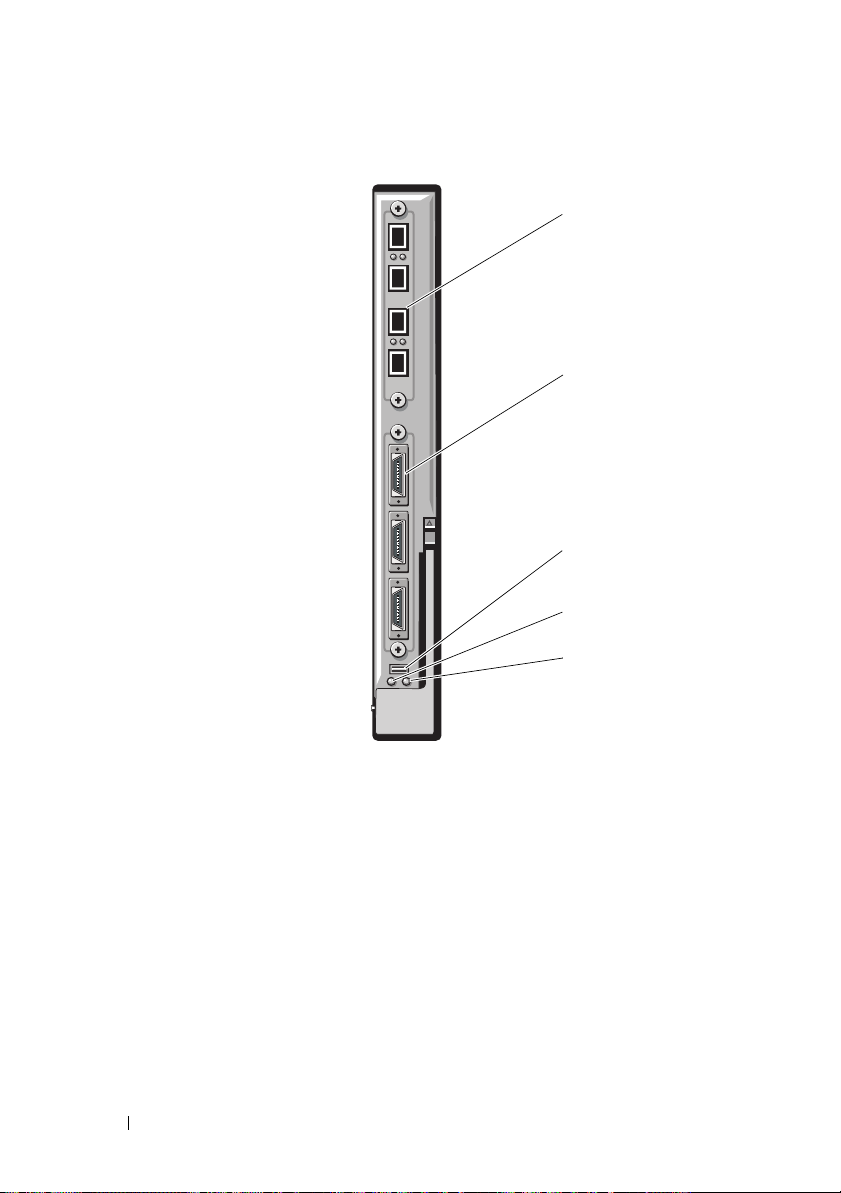
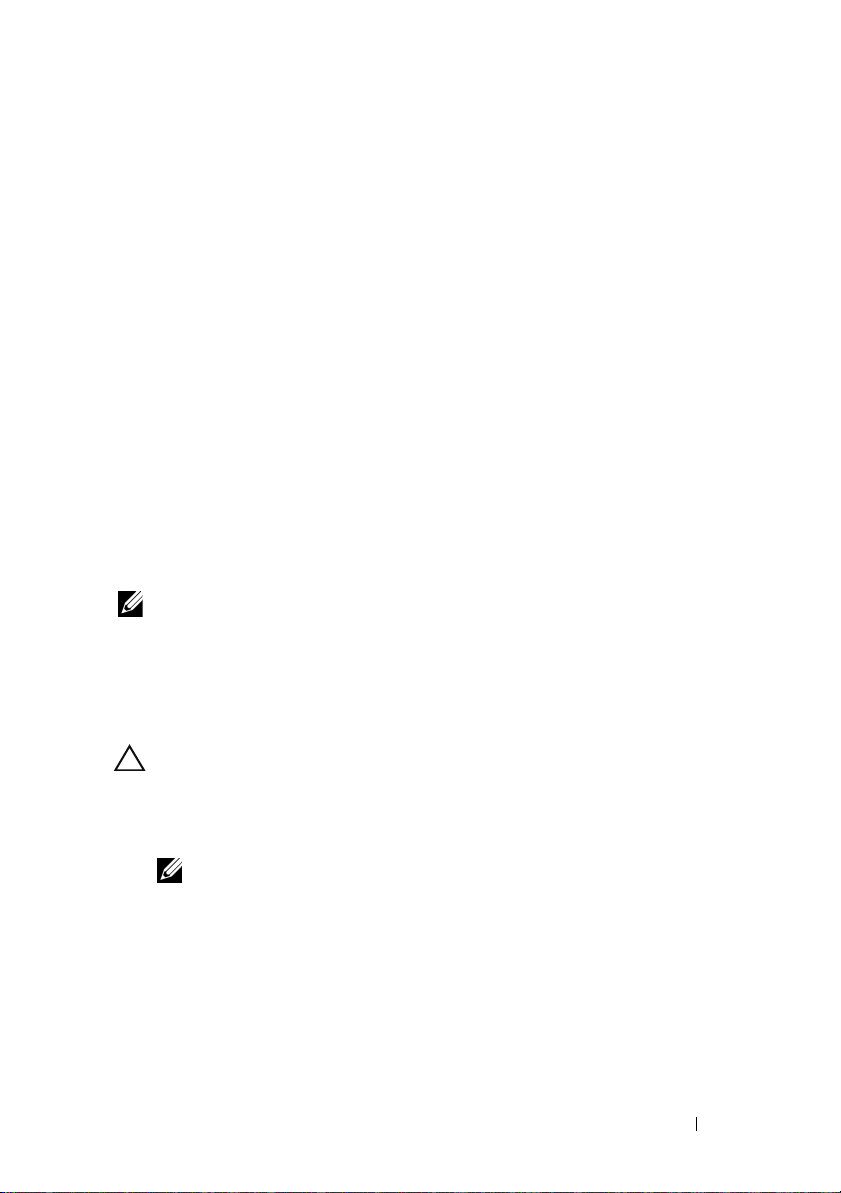
Figure 1-1. PowerConnect M8024 Switch Module
1
2
3
4
5
1 optional module with four SFP+
ports
3 serial connector for optional USB
type-A form-factor cable
5 status/identification indicator
16 Information Update
2 optional module with three CX4
ports
4 module power indicator
Page 17
Mellanox M2401G Infiniband Switch I/O Module
The Mellanox M2401G Infiniband switch I/O module includes 24 4x DDR
Infiniband ports. Eight ports are external uplink ports, while 16 internal ports
provide connectivity to the blades in the enclosure.
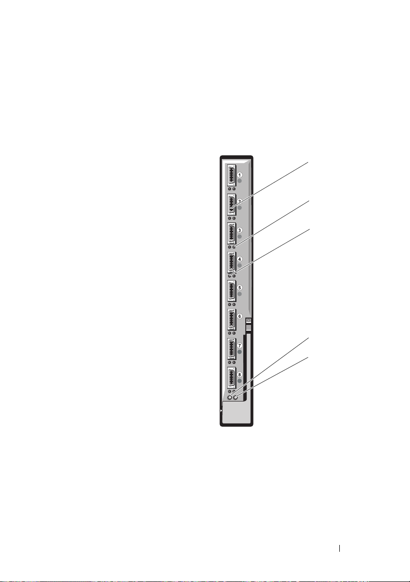
Figure 1-2. Mellanox M2401G Infiniband Switch Module
1
2
3
4
5
1 Infiniband ports (8) 2 port link status indicators (8)
3 port activity indicators (8) 4 module power indicator
5 status/identification indicator
Information Update 17
Page 18

Table 1-5. Mellanox M2401G Infiniband Switch Indicators
Indicator Pattern Description
Link indicator Green, on Physical link established
Green, off No physical link present
Activity
indicator
Amber, on Valid logical link to Infiniband network
established
Amber, blinking Data transfer is occurring
Amber, off No logical link to Infiniband network
Brocade M5424 FC8 I/O Module
The Brocade M5424 I/O module includes eight external autosensing Fibre
Channel ports (four ports are enabled in the standard configuration and four
additional ports may be enabled as an optional upgrade), 16 internal ports,
and one serial port with an RJ-45 connector. The external Fibre Channel ports
operate at 8 Gb/sec, 4 Gb/sec, or 2 Gb/sec.
NOTE: CMC firmware version 1.3 is required to support FC8 mezzanine cards
and I/O modules.
NOTE: This Fibre Channel switch module includes Short Wave Small Form Factor
Pluggable (SFP) optical transceivers. To ensure proper functionality, use only SFPs
provided with this module.
18 Information Update
Page 19
Figure 1-3. Brocade M5424 FC8 I/O Module
1
2
3
4
5
6
7
1 Fibre Channel port (8) 2 Fibre Channel port status
indicator (8)
3 Fibre Channel port speed
indicator (8)
5 status indicator 6 module power indicator
7 status/identification indicator
4 serial port (RJ-45 connector)
Information Update 19
Page 20

Table 1-6. Brocade M5424 FC8 I/O Module
Indicator Type Pattern Description
Fibre Channel
port status
indicator
Fibre Channel
port speed
indicator
Module status
indicator
Module power
indicator
Status/
identification
indicator
Off No signal carrier
Amber on Signal present but not online
Green on Online, but no activity
Green blinking
slowly
Green blinking
quickly
Green flickering I/O activity on port
Amber blinking
slowly
Amber blinking
rapidly
Off 2 Gb link established
Green on 4 Gb link established
Amber on 8 Gb link established
Off Module is off or enclosure power is off.
Green on All ports are ready for use.
Amber on Module is booting being reset, or ports are offline.
Green/amber
blinking
Off Power to the module is off.
Green Module has power.
Blue on Primary module in a stack, if applicable
Blue off Secondary module in a stack
Amber flashing Fault condition in module
Online but segmented
Internal loopback
Port disabled
Error or fault with port
Diagnostic message is in error log, or
environmental range is exceeded.
20 Information Update
Page 21
Updates on Hard Drive Installation
• The PowerEdge M805 and M905 blades support one or two
2.5-inch SAS
hard-disk drives.
• The PowerEdge M710 blade supports one to four 2.5 inch SAS hard drives.
• The PowerEdge M610, M600 and M605 blades support one or two 2.5inch SATA hard drives, one or two 2.5-inch SAS hard drives,
or one or two solid-state disk (SSD) hard drives.
NOTE: SAS and SATA hard drives cannot be mixed within a blade.
NOTE: Hot-plug operation is supported if an optional RAID controller card
is installed.
NOTE: SATA hard drives are not hot swappable with the SATA repeater
daughter card.
CAUTION: To ensure proper airflow for cooling of the blade, each hard drive bay
must contain either an active hard drive or a drive blank.
Hard-Drive Installation Guidelines
• If a RAID controller storage card is installed, the blade supports hot-plug
drive removal and installation.
• If less than the maximum number of hard drives are installed, hard drive
blanks must be installed to maintain proper cooling airflow.
Installing a Hard Drive
NOTE: When a replacement hot-swappable hard drive is installed and the blade
is powered on, the hard drive automatically begins to rebuild. Ensure that the
replacement hard drive is blank or contains data that you wish to have over-written.
Any data on the replacement hard drive is immediately lost after the hard drive is
installed.
NOTE: Not all operating systems support hot-plug drive installation.
See the documentation supplied with your operating system.
Information Update 21
Page 22
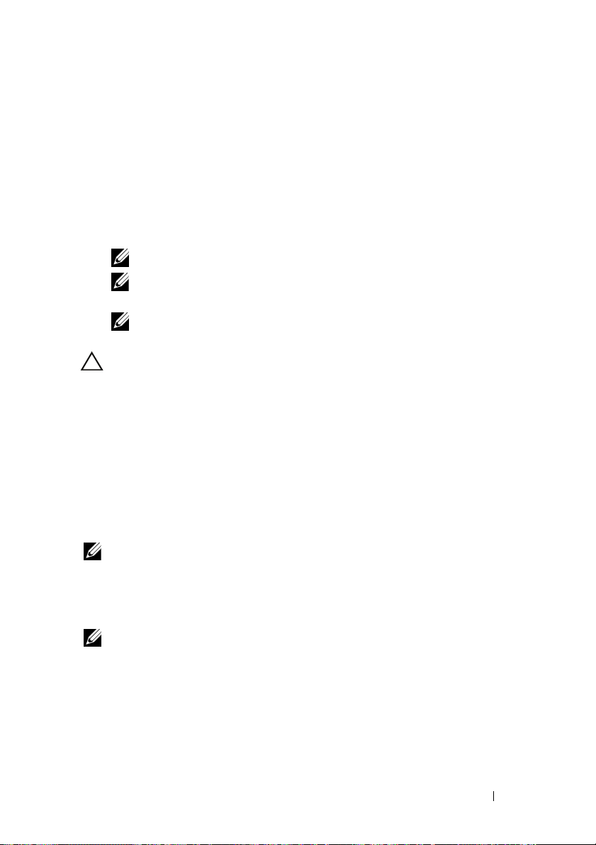
1
Open the hard-drive carrier handle. See Figure 1-4.
Figure 1-4. Installing a Hard Drive
3
2
1
1 hard drive 2 carrier handle
3 release button
2
Insert the hard-drive carrier into the drive bay. Carefully align the channel
on the hard drive carrier with the appropriate drive slot on the blade.
3
Push the drive carrier into the slot until the handle makes contact with
the blade.
4
Rotate the carrier handle to the closed position while pushing the carrier
into the slot until it locks into place.
The status LED indicator displays a steady green light if the drive is
installed correctly. The drive carrier LED green indicator flashes as the
drive rebuilds. If the drive carrier LED does not light, see "Troubleshooting
SAS and SATA Drives" in your
Hardware Owner’s Manual
.
22 Information Update
Page 23

Removing a Hard Drive
NOTE: Not all operating systems support hot-plug drive installation. See the
documentation supplied with your operating system.
1
Take the hard drive offline and wait until the hard-drive indicator codes
on the drive carrier signal that the drive may be removed safely.
When all indicators are off, the drive is ready for removal.
See your operating system documentation for more information on taking
the hard drive offline.
2
Open the hard-drive carrier handle to release the drive. See Figure 1-4.
3
Slide the hard drive out until it is free of the drive bay.
If you are permanently removing the hard drive, install a blank insert.
Shutdown Procedure for Servicing a Hard Drive
NOTE: This section applies only to situations where the blade must be powered
down to service a hard drive. In many situations, the hard drive can be serviced
while the blade is powered on.
If you need to power off the blade to service a hard drive, wait 30 seconds
after the blade’s power indicator turns off before removing the hard drive.
Otherwise, the hard drive may not be recognized after the hard drive is
reinstalled and the blade is powered on again.
Configuring the Boot Drive
The drive or device from which the system boots is determined by the boot
order specified in the System Setup program. See "Using the System Setup
Program and UEFI Boot Manager" in the Hardware Owner’s Manual.
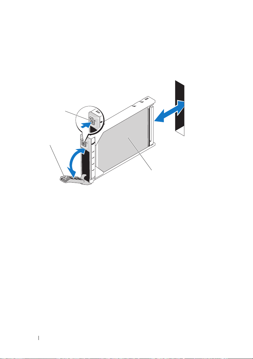
Removing a Hard Drive From a Hard-Drive Carrier
CAUTION: Always wear a wrist grounding strap when handling equipment
with static-sensitive components.
If you are replacing a drive in the carrier, remove the four screws from the slide
rails on the hard-drive carrier and separate the hard drive from the carrier.
See Figure 1-5.
Information Update 23
Page 24

Installing a Hard Drive In a Drive Carrier
1 Insert the hard drive into the hard-drive carrier with the drive’s
controller board’s connector end of the drive at the back of the carrier.
See Figure 1-5.
2 From the back of the carrier, slide the drive into the carrier until it
contacts the stop tab on the front of the carrier.
3
Align the screw holes on the hard drive with the holes on the hard-drive
carrier. For SATA drives, align the drive mounting holes with the carrier
mounting holes marked
4 Attach the four screws to secure the hard drive to the hard-drive carrier.
CAUTION: To avoid damaging the drive or the carrier, do not overtighten
the screws.
SATA
. See Figure 1-5.
24 Information Update
Page 25
Figure 1-5. Removing and Installing a Hard Drive In a Drive Carrier
1
2
3
1 hard drive 2 drive carrier
3 screws (4)
Information Update 25
Page 26

26 Information Update
Page 27

Dell™ PowerEdge™ M905
、
M805、M710、M610
M605
和
M600
系统
信息更新
、
Page 28

注和小心
注:“注”表示可以帮助您更好地使用计算机的重要信息。
小心:“小心”表示如果不遵循说明,就有可能损坏硬件
或导致数据丢失。
___________________
本说明文件中的信息如有更改,恕不另行通知。
© 2008-2009 Dell Inc.
未经
Dell Inc.
本文中使用的商标:
是
Dell Inc.
在美国和/或其它国家/地区的商标或注册商标。
本说明文件中述及的其它商标和产品名称是指拥有相应商标和产品名称的公司或其制造的
产品。
2009 年 8 月 Rev. A05
书面许可,严禁以任何形式复制这些材料。
的商标;
Dell Inc.
版权所有,翻印必究。
Dell、DELL
Microsoft、Windows 和 Windows Server 是 Microsoft Corporation
对本公司的商标和产品名称之外的其它商标和产品名称不拥有任何专有权。
徽标、
PowerEdge、PowerConnect 和 OpenManage
Page 29
Microsoft®
以下问题已记录到
•
运行
Microsoft® Windows Server® 2003 或 Windows Server 2008
果安装有
请参阅知识库文章:
•
运行
则不支持
iSCSI
请参阅知识库文章:
4 GB
Windows Server 2008
iSCSI
引导无法工作。这是
更新
Microsoft
以上的内存,则不能设置进入休眠模式。有关详情,
引导。此外,当外部
帮助和支持网站
support.microsoft.com/kb/888575
的系统如果在内部
Microsoft
support.microsoft.com/kb/968410
support.microsoft.com
模块中安装有
SD
存储设备插入系统时,
USB
已知的问题。有关详情,
的系统如
。
SD
。
:
卡,
Dell Update Package
在安装
相关的消息:
Dell Update Package (DUP)
注:这些消息仅供参考。
•
Windows hardware detection
•
Windows hardware configuration problem
•
Re-enumeration of VFlash and momentary drive letter changes in
Windows
小心:建议在
•
关闭与
需要重新引导系统
(
Windows 中 VFlash
上安装
VFlash
Unified Server Configurator
注:仅当完整消息显示后才能重新引导系统
信息
的过程中,您可能会看到与下列情况
(
Windows
重新枚举和驱动器号临时更改)
的过程中不要执行任何写操作。
DUP
硬件检测)
(
Windows
驱动程序或诊断存储库之后,
硬件配置问题)
信息更新 29
Page 30

内存电源和性能管理的选项
Power Management
Maximum Performance
(电源管理)屏幕中的内存电源和性能管理选项有
(最佳性能)、指定频率或
(最低性能)。
系统内存 —
PowerEdge M710
下表是《硬件用户手册》中表
物理
内存
总容量
24 GB
内存模块
数量和
—
类型
12 个 2-GB
RDIMM
内存模块位置处理器
A2、A3
A5、A6
A8、A9
B2、B3
B5、B6
B8、B9
系统规格更新
内存 —
Dell™ PowerEdge™ M905 和 Dell PowerEdge M805
体系结构
3-5“PowerEdge M710
两个 高级
、
、
、
、
、
内存模块,额定运行速率为
DDR2
Minimum Power
内存配置示例”的补充。
内存
模式
ECC
可用
内存
24 GB
800 MHz
30 信息更新
Page 31

PowerEdge
刀片 —
(四端口夹层卡)
模块端口映射
I/O
下表说明带有四端口夹层卡的半高刀片的
表示从
n
表
刀片
集成
集成
Mezz_FAB_B_Blade n_Port1
Mezz_FAB_B_Blade n_Port2
Mezz_FAB_B_Blade n_Port3
Mezz_FAB_B_Blade n_Port4
Mezz_FAB_C_Blade n_Port1
Mezz_FAB_C_Blade n_Port2
Mezz_FAB_C_Blade n_Port3
Mezz_FAB_C_Blade n_Port4
1 到 16
注:有关每个
上的文档
(《
M1000e
1-1. I/O
n I/O
LOM1
LOM2
的变量值。
PowerEdge
Quadport Capable Hardware For the M1000e Modular Chassis
模块化机箱所用的四端口硬件》)。
模块端口分配 — 半高刀片
系统映射的详情,请参阅
A1 B1 C1 C2 B2 A2
端口
n
端口
n
端口
(n+16)
模块端口映射。在下表中,
I/O
support.dell.com/manuals
模块
端口
端口
(n+16)
端口
n
端口
n
端口
(n+16)
端口
(n+16)
端口
n
n
信息更新 31
Page 32

下表说明带有四端口夹层卡的全高刀片的
下符号:
•n 表示从
•
LOM1
(
n
+8) 的 LOM
注:有关每个
上的文档
(《
M1000e
1 到的 8
和
LOM2
Quadport Capable Hardware For the M1000e Modular Chassis
的变量值
是刀片
n 的 LOM
端口,
端口
PowerEdge
模块化机箱所用的四端口硬件》)。
系统映射的详情,请参阅
模块端口映射。表中使用以
I/O
LOM3 和 LOM4
support.dell.com/manuals
是刀片
表
1-2. I/O
刀片
集成
集成
集成
集成
Mezz_FAB_B_Blade n_Port1
Mezz_FAB_B_Blade n_Port2
Mezz_FAB_B_Blade n_Port3
Mezz_FAB_B_Blade n_Port4
Mezz_FAB_C_Blade n_Port1
Mezz_FAB_C_Blade n_Port2
Mezz_FAB_C_Blade n_Port3
Mezz_FAB_C_Blade n_Port4
Mezz_FAB_B_Blade
n+8_Port1
模块端口分配 — 全高刀片
和刀片
n
LOM1
LOM2
LOM3
LOM4
(n + 8) I/O
模块
A1 B1 C1 C2 B2 A2
端口
n
端口
端口
(n+8)
端口
(n+8)
端口
n
端口
n
端口
(n+16)
端口
(n+16)
端口
n
端口
n
端口
(n+16)
端口
(n+16)
端口
(n+8)
n
32 信息更新
Page 33

表
1-2. I/O
刀片
Mezz_FAB_B_Blade
n+8_Port2
Mezz_FAB_B_Blade
n+8_Port3
Mezz_FAB_B_Blade
n+8_Port4
Mezz_FAB_C_Blade
n+8_Port1
Mezz_FAB_C_Blade
n+8_Port2
Mezz_FAB_C_Blade
n+8_Port3
Mezz_FAB_C_Blade
n+8_Port4
模块端口分配 — 全高刀片 (续)
和刀片
n
(n + 8) I/O
模块
A1 B1 C1 C2 B2 A2
端口
(n+8)
端口
(n+24)
端口
(n+24)
端口
(n+8)
端口
(n+8)
端口
(n+24)
端口
(n+24)
PowerEdge
刀片 — 四端口夹层卡的兼
容性值表
下表显示
PowerEdge
表中使用以下符号。
•X 表示
•
IOM
空白值表示
•"无"表示半高刀片所对应的结构不存在。
刀片系统与四端口夹层卡的兼容性。
结构上支持夹层卡端口。
结构上不支持夹层卡端口。
IOM
信息更新 33
Page 34

表
四端口夹层卡的配置值表
1-3.
PowerEdge
刀片
M710 XXXXXXX
M905 X X X X
M805 X X X X
M605 X X
M610 X X X X
M600 X X X X
PowerEdge M905、M805 和 M710
模块端口映射 (双端口夹层卡)
I/O
下表更正了《硬件用户手册》“关于系统”章节中表
表
1-4. I/O
刀片
1 I/O
集成
LOM1
集成
LOM2
Mezz1_Fab_C
Mezz2_Fab_B
Mezz3_Fab_C
Mezz4_Fab_B
结构
B1
端口
和
模块端口映射 — 全高刀片
端口
1
2
3
和
4
A1 B1 C1 C2 B2 A2
端口
端口
1
9
端口
和
2
端口
端口
结构
1
C1
端口
3
和
4
端口 1端口
1
端口 9端口
9
结构
B2
端口
和
无无无无
无无无无
无无无无
端口
1
2
和
3
4
端口
和
2
结构
1
刀片 —
的部分内容。
1-12
模块
端口
端口
1
端口
1
9
端口
9
C2
端口
和
1
9
3
4
34 信息更新
Page 35

刀片
4I/O
A1 B1 C1 C2 B2 A2
集成
集成
LOM1
LOM2
端口
端口
4
12
Mezz1_Fab_C
Mezz2_Fab_B
端口
Mezz3_Fab_C
Mezz4_Fab_B
端口
端口 4端口
4
端口
12
模块
12
端口
4
12
端口
端口
4
12
端口
端口
4
12
刀片
8 I/O
A1 B1 C1 C2 B2 A2
集成
集成
LOM1
LOM2
端口
端口
8
16
Mezz1_Fab_C
Mezz2_Fab_B
端口
Mezz3_Fab_C
Mezz4_Fab_B
刀片
6 I/O
端口
A1 B1 C1 C2 B2 A2
集成
集成
LOM1
LOM2
端口
端口
6
14
Mezz1_Fab_C
Mezz2_Fab_B
端口
Mezz3_Fab_C
Mezz4_Fab_B
端口
8
16
6
14
端口
端口
端口
端口
模块
8
16
模块
6
14
端口
端口
端口
端口
8
16
6
14
端口
端口
端口
端口
8
16
6
14
端口
端口
端口
端口
8
16
6
14
信息更新 35
Page 36

PowerEdge
版本要求
™ 刀片 —
Dell™OpenManage™
PowerEdge M905 和 M805
OpenManage
注:
PowerEdge M610 和 M710
件为
6.0.1
注:
M805 或 M905
PowerEdge
PowerEdge M905 和 M805
PowerEdge M610 和 M710
如果您将这些刀片装在
新刀片将无法通电。
注:请参阅
以了解有关如何配置和操作
更新
CMC
下载
CMC
在开始固件更新之前,从
件版本,并保存到您的本地系统。
固件包包含以下软件组件:
CMC
•
编译的
•
基于
•
默认配置文件
使用
Firmware Update
最新版本。
注:请参阅
以了解有关如何配置和操作
注:默认情况下,固件更新会保留当前的
可以选择将
系统管理软件。
OpenManage 5.4.3
版或更高版本。
OpenManage 6.0.1
刀片。
刀片 —
support.dell.com
固件
固件
固件代码和数据
CMC
的界面、
Web
support.dell.com
CMC
刀片要求使用
版不支持
刀片要求
版不支持
CMC
刀片要求
刀片要求
固件版本更低的
CMC
上的最新《
CMC
support.dell.com Web
和其它用户界面数据文件
JPEG
(固件更新)页面,将
上的最新《
CMC
配置设置重设为出厂默认设置。
版或更高版本的
5.4.3
PowerEdge M600 或 M605
OpenManage
PowerEdge M600、M605
系统管理软
固件要求
固件为
CMC
固件为
CMC
M1000e
机箱管理控制器用户指南》
Dell
模块的完整说明。
CMC
机箱管理控制器用户指南》
Dell
模块的完整说明。
CMC
版或更高版本。
1.2
版或更高版本。
2.0
站点下载最新的固
固件更新为
设置。更新过程中,
刀片。
、
机壳上,
36 信息更新
Page 37

更新冗余
小心:在冗余
致在
CMC
1
使用
页面(位于
备用
蓝色,备用
2
首先更新备用
CMC
3
使用
CMC
4
重新引导备用
请留出
请参阅“使用基于
更新
5
使用
配置中的固件
CMC
CMC
故障转移或故障回复期间出现意外行为。使用以下步骤进行冗余
CMC
部署。
RACADM
CMC
getsysinfo
Web-based interface [
。可以看到主
或次级
CMC
CMC
固件”或“使用
getsysinfo
命令或通过基于
的固件已达到所要求的水准。
CMC
分钟引导备用
10
Web
固件”。
CMC
getsysinfo
命令或通过基于
的固件已达到所要求的水准。
6
一旦两个
命令将左插槽中的
都更新为相同的固件修订版本,使用
CMC
CMC
配置中,必须更新两个模块的
命令或使用
CMC
CMC
Chassis Summary
基于
或活动
的界面] 中)查找次级或
Web
模块的状态指示灯呈纯
CMC
的指示灯不亮。
上的固件。请参阅“使用基于
RACADM
更新
的界面验证次级
Web
后,更新活动或主
。
CMC
的界面更新
重设为主
CMC
的界面验证活动
Web
CMC
固件”。
CMC
上的固件。
CMC
固件”或“使用
。
固件。否则可能会导
CMC
(机箱摘要)
的界面更新
Web
CMC
RACADM
CMC
cmcchangeover
或备用
或主
CMC
使用基于
1
登录到基于
中的“使用基于
2
单击系统树中的
3
单击
的界面更新
Web
Update
固件
CMC
的界面。请参阅
Web
的界面登录到
Web
Chassis
(机箱)。
M1000e《
(更新)选项卡。此时将会显示
(可更新组件)页。
4
在
Updatable Components
显示
Firmware Update
5
在
径,或单击
注:默认
名始终相同,所以必须分开保存不同的固件版本。
(值)字段中键入固件映像文件驻留的管理站或共享网络的路
Va l u e
CMC
(浏览)导航到文件位置。
Browse
固件映像名称为
(可更新组件)页面上,单击
(固件更新)页面。
firmimg.cmc
配置指南》
CMC”
。
Updatable Components
CMC
,且文件名不可更改。由于文件
信息更新 37
名称。
Page 38

6
单击
Update
7
单击
Yes
“
Firmware Update in Progress.
完成,将重设
(用户界面)页面以再次登录。
(更新)。显示一个对话框,要求您确认刚才的操作。
(是)继续。固件传输过程将开始,显示的状态消息为
。重设完成后,将需要刷新
CMC
”(正在更新固件。)
User Interface
CMC
更新一旦
使用
RACADM 更新 CMC
1
打开
2
键入:
racadm fwupdate -g -u -a <TFTP
-d <
请参阅
support.dell.com
解有关如何配置和操作
命令行控制台并登录。
CMC
文件路径
PowerEdge M905 和 M805
以下信息是对《硬件用户手册》中的内存备用小节以及这些刀片的系统信
息标签的更新。
固件
服务器
IP
> -m <cmc-active|cmc-standby>
上的最新《
模块的完整说明。
CMC
机箱管理控制器用户指南》以了
Dell
刀片—内存备用要求
地址
>
PowerEdge M905
如果已安装了
个完全相同的内存模块
24
(DIMM)
,则可支持内存备用。
PowerEdge M805
如果已安装了
个完全相同的内存模块,则可支持内存备用。
16
38 信息更新
Page 39

新夹层卡
您的刀片目前支持以下附加的夹层卡:
Intel
®
Gigabit ET
四端口夹层卡。请参阅第 第
页上的“四端口夹层
34
•
卡的配置值表”,以获取有关支持值表的信息。
•
系列刀片的
M
请参阅第 第
Broadcom NetXExtreme II 5709
页上的“四端口夹层卡的配置值表”,以获取有关支持
34
四端口以太网夹层卡。
值表的信息。
•
用于
II 57711
•
Broadcom 57710 10Gb
•
Emulex LPe1205-M FC8
•
ConnectX MDI QDR
注:需要
注:需要
系列刀片,且带有
M
双端口
10 Gb
固件版本
CMC
固件版本
CMC
TOE 和 iSCSI
卸载的
以太网夹层卡
以太网卡
卡
才能支持
1.3
才能支持夹层卡中的链接调节。
2.0
FC8
夹层卡和
Broadcom NetXtreme
模块。
I/O
有关夹层卡的信息,请参阅《硬件用户手册》中的“安装系统组件”。
有关配置特定卡的详情,请参阅
support.dell.com
上该卡的说明文件。
信息更新 39
Page 40

新
您的系统现在支持以下附加
•
•
•
•
这些模块可以热交换,并且可安装到结构
他详细信息:
•
•
•
模块
I/O
模块:
I/O
™
Dell PowerConnect
Mellanox M2401G DDR Infiniband
Brocade M5424 FC8
Mellanox M3601Q QDR Infiniband
注:需要
M8024
以
由于
安装此交换机模块时将跨越
有关安装
中的“
CMC
以太网交换机模块还可以安装到结构
的速度运转。
1 Gb
M3601Q QDR
模块的一般信息,请参阅《硬件用户手册》
I/O
模块”。
I/O
M8024 10 Gb
交换机模块
固件版本
才能支持
1.3
交换机的双宽特性以及
I/O
以太网交换机模块
交换机模块
交换机模块
FC8
模块组的结构
夹层卡和
或结构C 中。请注意以下其
B
M1000e
模块。
I/O
中,但在此结构中将仅
A
的物理限制,
B 和 C
。
PowerConnect M8024 10 Gb
PowerConnect M8024
•
带有四个光学
•
带有三个铜缆
这些模块可任意组合使用,并且单独销售。
可以使用以下两种方法中的任一种初始配置交换机:
•
使用可选的
机,然后使用终端应用程序配置该交换机。
•
使用
iKVM CMC
CMC CLI
(
一旦将
Telnet 和 http
40 信息更新
用户指南)。
CMC
地址分配给管理
IP
均通过该网络可用。
交换机模块整合了两个可选的托架支持以下模块:
SFP+
CX4
USB A
控制台(“第
命令。有关详情,请参阅
以太网交换机
连接器的
上行链路的
类外形尺寸串行电缆将外部管理系统连接至交换
VLAN
10 Gb
或接口并且交换机连接至管理网络后,
以太网模块
10 Gb
个刀片”)和
17
CMC user's guide
模块
I/O
以太网模块
connect switch-n
Page 41

图
1-1. PowerConnect M8024
交换机模块
1
2
3
4
5
1
带有四个
选模块
3
用于可选的
尺寸电缆的串行连接器
5
状态/标识指示灯
SFP+
端口的可
USB A
类外型
2
带有三个
4
模块电源指示灯
端口的可选模块
CX4
信息更新 41
Page 42

Mellanox M2401G Infiniband
Mellanox M2401G Infiniband
Infiniband
端口。其中
口可连接到机壳中的刀片。
个是外部上行链路端口,另外
8
交换机
交换机
I/O
I/O
模块
模块包括
24 个 4x DDR
个内部端
16
图
1-2. Mellanox M2401G Infiniband
交换机模块
1
2
3
4
5
1
Infiniband
3
端口活动指示灯(8 个)
5
状态/标识指示灯
42 信息更新
端口(8 个)
2
端口链路状态指示灯(8 个)
4
模块电源指示灯
Page 43

表
1-5. Mellanox M2401G Infiniband
指示灯 显示方式 说明
链接指示灯 绿色,亮起 已建立物理链接
绿色,不亮 没有建立物理链接
活动指示灯 琥珀色,亮起 已建立与
琥珀色、
正在闪烁
琥珀色,不亮 没有建立与
交换机指示灯
Infiniband
正在进行数据传输
Infiniband
网络有效的逻辑链接
网络的逻辑链接
Brocade M5424 FC8 I/O
Brocade M5424 I/O
模块
模块包括八个外部自动感应的光纤信道端口(标准配
置中启用四个端口,而另四个端口可作为可选的升级端口来启用)、
个内部端口以及一个使用
16
以
秒、
8 Gb/
注:需要
注:此光纤信道交换机模块包含短波小型可插拔
为了确保正常工作,请仅使用此模块附带的
4 Gb/
CMC
秒或
2 Gb/
固件版本
1.3
连接器的串行端口。外部光纤信道端口
RJ-45
秒的速度运转。
才能支持
FC8
夹层卡和
。
SFP
模块。
I/O
光学收发器。
(SFP)
信息更新 43
Page 44

图
1
1-3. Brocade M5424 FC8 I/O
模块
2
3
4
5
6
1
光纤信道端口(8 个)
3
光纤信道端口速度指示灯
(8 个)
5
状态指示灯
7
状态/标识指示灯
44 信息更新
2
光纤信道端口状态指示灯
(8 个)
4
串行端口(
6
模块电源指示灯
RJ-45
7
连接器)
Page 45

表
1-6. Brocade M5424 FC8 I/O
指示灯类型 显示方式 说明
光纤信道端口
状态指示灯
光纤信道端口
速度指示灯
模块状态
指示灯
模块电源
指示灯
状态
/
标识指
示灯
不亮 无信号载体
琥珀色亮起 信号出现但未联机
绿色亮起 联机,但无活动
绿色缓慢闪烁 联机但已分段
绿色快速闪烁 内部环回
绿色闪烁 端口上有
琥珀色缓慢闪烁 端口已禁用
琥珀色快速闪烁 端口错误或故障
不亮
绿色亮起
琥珀色亮起
不亮 模块关闭或机壳电源关闭。
绿色亮起 所有端口均已准备就绪。
琥珀色亮起 模块正在引导重设,或端口脱机。
绿色/琥珀
色闪烁
不亮 模块电源关闭。
绿色 模块已通电。
蓝色亮起 堆栈中的主要模块 (如果可用)
蓝色熄灭 堆栈中的备用模块
琥珀色闪烁 模块出现故障
模块
2 Gb
4 Gb
8 Gb
错误日志中的诊断消息,或超出环境范围。
活动
I/O
链接已建立
链接已建立
链接已建立
信息更新 45
Page 46

硬盘驱动器安装上的更新
•
PowerEdge M805
和
M905
刀片支持一个或两个
2.5
英寸
SAS
驱动器。
•
PowerEdge M710
•
PowerEdge M610
硬盘驱动器、一个或两个
态磁盘
(SSD)
注:不能在刀片内混合使用
注:如果安装了可选的
注:
SATA
小心:为了确保冷却刀片所需的良好通风,每个硬盘驱动器托架必须包含
活动硬盘驱动器或驱动器挡片。
刀片支持一到四个
、
M600 和 M605
2.5 英寸 SAS
硬盘驱动器。
RAID
硬盘驱动器不可与
2.5 英寸 SAS
刀片支持一个或两个
硬盘驱动器。
2.5 英寸 SATA
硬盘驱动器或者一个或两个固
SAS 和 SATA
控制器卡,则支持热插拔操作。
SATA
硬盘驱动器。
中继器子卡进行热交换。
硬盘驱动器安装原则
•
如果安装了
控制器存储卡,则刀片支持卸下和安装热插拔驱
RAID
动器。
•
如果安装的硬盘驱动器少于最大数目,则必须安装硬盘驱动器挡板以
保持良好的冷却通风。
安装硬盘驱动器
注:当安装更换的可热交换硬盘驱动器并接通刀片电源后,硬盘驱动器将
自动开始重建。确保更换的硬盘驱动器为空白或包含要覆盖的数据。
安装硬盘驱动器后,更换的硬盘驱动器上的任何数据均将立即丢失。
注:并非所有操作系统都支持热插拔驱动器的安装。请参阅操作系统附带
的说明文件。
硬盘
46 信息更新
Page 47

1
打开硬盘驱动器托盘手柄。请参阅图
1-4
。
图
安装硬盘驱动器
1-4.
3
2
1
3
2
将硬盘驱动器托盘插入到驱动器托架中。小心地将硬盘驱动器托盘上
硬盘驱动器
释放按钮
2
1
托盘手柄
的通道与刀片上相应的驱动器插槽对齐。
3
将驱动器托盘推入到插槽中,直至手柄触及刀片。
4
将托盘推入到插槽时,将托盘手柄转动至闭合位置,直至其锁
定到位。
如果正确安装了驱动器,则
重建驱动器时,驱动器托盘
未亮,请参阅《硬件用户手册》中的“
LED
状态指示灯会呈绿色稳定亮起。
LED
绿色指示灯将闪烁。若驱动器托盘
LED
SAS 和 SATA
故障排除”。
驱动器
信息更新 47
Page 48

卸下硬盘驱动器
注:并非所有操作系统都支持热插拔驱动器的安装。请参阅操作系统附带
的说明文件。
1
使硬盘驱动器脱机并等待,直至驱动器托盘信号中的硬盘驱动器指示
灯代码表示可以安全卸下该驱动器。
当所有指示灯均不亮时,便可以卸下驱动器。
有关使硬盘驱动器脱机的详情,请参阅操作系统说明文件。
2
打开硬盘驱动器托盘手柄以松开驱动器。请参阅图
3
向外滑动硬盘驱动器,直至其脱离驱动器托架。
1-4
。
如果要永久拆除硬盘驱动器,请安装挡板插件。
维修硬盘驱动器的关机程序
注:本节仅适用于必须关闭刀片电源才能维修硬盘驱动器的情况。
在许多情况下,可以在刀片通电时维修硬盘驱动器。
如果需要关闭刀片电源来维修硬盘驱动器,请在刀片的电源指示灯熄灭后
等待
秒,然后卸下硬盘驱动器。否则,硬盘驱动器重新安装并再次接
30
通刀片电源后,硬盘驱动器可能无法识别。
配置引导驱动器
系统从哪个驱动器或设备进行引导取决于在系统设置程序中指定的引导顺
序。请参阅《硬件用户手册》中的“使用系统设置程序和
理器”。
UEFI
引导管
从硬盘驱动器托盘卸下硬盘驱动器
小心:处理带有静电敏感组件的设备时,应始终佩戴接地腕带。
如果更换托盘中的驱动器,请从硬盘驱动器托盘上的滑轨卸下四个螺钉并
将硬盘驱动器与托盘分离。请参阅图
48 信息更新
1-5
。
Page 49

在驱动器托盘中安装硬盘驱动器
1 将硬盘驱动器插入到硬盘驱动器托盘中,使驱动器控制器板的连接
器端位于托盘后部。请参阅图
2 从托盘的后部将驱动器滑入托盘,直至其触及托盘前端的停止
卡舌。
将硬盘驱动器上的螺孔与硬盘驱动器托盘上的孔对齐。对于
3
驱动器,将驱动器固定孔与标记为
请参阅图
1-5
。
4 装上四颗螺钉以将硬盘驱动器固定到硬盘驱动器托盘中。
小心:为避免损坏托盘或驱动器,请不要过度拧紧螺钉。
1-5
。
的托盘固定孔对齐。
SATA
SATA
信息更新 49
Page 50

图
在驱动器托盘中卸下和安装硬盘驱动器
1-5.
1
2
3
1
3
50 信息更新
硬盘驱动器
螺钉(4 颗)
2
驱动器托盘
Page 51

Systèmes Dell™
PowerEdge™ M905, M805,
M710, M610, M605 et M600
Mise à jour des
informations
Page 52

Remarques et précautions
REMARQUE : Une REMARQUE indique des informations importantes qui peuvent
vous aider à mieux utiliser votre ordinateur.
PRÉCAUTION : Une PRÉCAUTION indique un risque de dommage matériel
ou de perte de données en cas de non-respect des instructions.
___________________
Les informations contenues dans ce document sont sujettes à modification sans préavis.
© 2008–2009 Dell Inc. Tous droits réservés.
La reproduction de ce document, de quelque manière que ce soit, sans l'autorisation écrite de Dell Inc.
est strictement interdite.
Marques mentionnées dans ce document : Dell, le logo DELL, PowerEdge, PowerConnect et
OpenManage sont des marques de Dell Inc.; Microsoft, Windows et Windows Server sont des marques
ou des marques déposées de Microsoft Corporation aux États-Unis et/ou dans d'autres pays.
D'autres marques commerciales et noms de marque peuvent être utilisés dans ce document pour faire
référence aux entités se réclamant de ces marques et de ces noms ou de leurs produits. Dell Inc. dénie
tout intérêt propriétaire vis-à-vis des marques commerciales et des noms de marque autres que les siens.
Août 2009 Rév. A05
Page 53

Mises à jour Microsoft
Les problèmes suivants sont documentés sur le site Web d'aide et de support
de Microsoft à l'adresse suivante : support.microsoft.com:
• Les systèmes fonctionnant sous Microsoft® Windows Server® 2003 ou
Windows Server 2008 ne peuvent pas passer en mode veille s'ils sont dotés
de plus de 4 Go de mémoire. Pour plus d'informations, consultez l'article
de la Base de connaissances concernant ce problème à l'adresse suivante :
support.microsoft.com/kb/888575
• Les systèmes fonctionnant sous Windows Server 2008 ne prennent pas en
charge l'amorçage iSCSI si une carte SD est installée dans leur module SD
interne. En outre, l'amorçage iSCSI ne fonctionne pas lorsqu'un
périphérique de stockage USB est inséré dans un port du système. Il s'agit
d'un problème connu par Microsoft. Pour plus d'informations, consultez
l'article de la Base de connaissances concernant ce problème à l'adresse
suivante :
support.microsoft.com/kb/968410
®
.
.
Informations sur le progiciel de mise à jour Dell
Au cours du processus d'installation du progiciel de mise à jour Dell (DUP),
il est possible que des messages concernant ce qui suit apparaissent :
REMARQUE : Ces messages apparaissent uniquement à titre d'indicatif.
• Détection de matériel dans Windows
• Problème de configuration du matériel dans Windows
• Ré-énumération des lettres relatives au support VFlash et aux lecteurs
dans Windows
PRÉCAUTION : Il est conseillé d'éviter l'exécution d'opérations de lecture
au cours de l'installation du progiciel de mise à jour sur VFlash.
• Demande de redémarrage du système après fermeture de l'interface
du pilote Unified Server Configurator ou du référentiel de diagnostics
REMARQUE : Redémarrez le système uniquement après l'affichage complet
du message.
Mise à jour des informations 53
Page 54

Options de la gestion de l'alimentation de la mémoire et des performances
Les options de gestion de l'alimentation de la mémoire et des performances
de l'écran Power Management (Gestion de l'alimentation) sont Maximum
Performance (Performances maximales), une valeur spécifiée ou Minimum
Power (Alimentation minimale).
Mémoire système - PowerEdge M710
Le tableau suivant est une annexe du tableau 3-5 du document Hardware
Owner’s Manual (Manuel du propriétaire). Il présente des exemples de
configurations mémoire du PowerEdge M710.
Total
Caractéristiques
physiques
Mémoire
24 Go 12 RDIMM de
Barrettes
de mémoire –
Nombre et type
2Go
Barrette
de mémoire
Emplacement
A2, A3, A5,
A6, A8, A9,
B2, B3, B5,
B6, B8, B9
Processeurs Mode
Mémoire
Deux Fonctions
ECC
avancées
Mémoire
Disponible
24 Go
Mise à jour des caractéristiques système
Mémoire — Dell™ PowerEdge™ M905 et Dell PowerEdge M805
Architecture Barrettes de mémoire DDR2, cadencées
un fonctionnement à 800 MHz
54 Mise à jour des informations
Page 55

Ensembles PowerEdge — Adressage des ports
du module d'E/S (cartes mezzanines
à quatre ports)
Le tableau ci-dessous illustre l'adressage des ports du module d'E/S d'un
ensemble mi-hauteur doté d'une carte mezzanine à quatre ports. Dans ce
tableau, la lettre n représente une valeur variable comprise entre 1 et 16.
REMARQUE : Pour l'adressage détaillé de chaque système PowerEdge,
voir le document Quadport Capable Hardware For the M1000e Modular Chassis
sur le site Web suivant : support.dell.com/manuals.
Tableau 1-1. Affectations des ports du module d'E/S - Ensembles mi-hauteur
Ensemble n Module d'E/S
A1 B1 C1 C2 B2 A2
Carte LOM1 intégrée Port n
Carte LOM2 intégrée Port n
Mezz_FAB_B_Blade n_Port1 Port n
Mezz_FAB_B_Blade n_Port2 Port n
Mezz_FAB_B_Blade n_Port3 Port
(n+16)
Mezz_FAB_B_Blade n_Port4 Port
(n+16)
Mezz_FAB_C_Blade n_Port1 Port n
Mezz_FAB_C_Blade n_Port2 Port n
Mezz_FAB_C_Blade n_Port3 Port
(n+16)
Mezz_FAB_C_Blade n_Port4 Port
(n+16)
Mise à jour des informations 55
Page 56

Le tableau ci-dessous illustre l'adressage des ports du module d'E/S
des ensembles pleine hauteur dotés de cartes mezzanines à quatre ports.
Les notations suivantes sont utilisées dans ce tableau :
•n
représente une valeur variable comprise entre 1 et 8
n
• LOM1 et LOM2 sont les ports LOM de l'ensemble
les ports LOM de l'ensemble (
REMARQUE : Pour l'adressage détaillé de chaque système PowerEdge,
voir le document Quadport Capable Hardware For the M1000e Modular Chassis
sur le site Web suivant : support.dell.com/manuals.
Tableau 1-2. Affectations des ports du module d'E/S - Ensembles pleine hauteur
Ensemble n et ensemble (n + 8) Module d'E/S
Carte LOM1 intégrée Port n
Carte LOM2 intégrée Port n
Carte LOM3 intégrée Port
Carte LOM4 intégrée Port
Mezz_FAB_B_Blade n_Port1 Port n
Mezz_FAB_B_Blade n_Port2 Port n
Mezz_FAB_B_Blade n_Port3 Port
Mezz_FAB_B_Blade n_Port4 Port
Mezz_FAB_C_Blade n_Port1 Port n
Mezz_FAB_C_Blade n_Port2 Port n
Mezz_FAB_C_Blade n_Port3 Port
Mezz_FAB_C_Blade n_Port4 Port
n
+8)
A1 B1 C1 C2 B2 A2
(n+8)
(n+16)
(n+16)
, et LOM3 et LOM4
(n+8)
(n+16)
(n+16)
56 Mise à jour des informations
Page 57

Tableau 1-2. Affectations des ports du module d'E/S - Ensembles pleine hauteur (suite)
Ensemble n et ensemble (n + 8) Module d'E/S
A1 B1 C1 C2 B2 A2
Mezz_FAB_B_Blade
n+8_Port1
Mezz_FAB_B_Blade
n+8_Port2
Mezz_FAB_B_Blade
n+8_Port3
Mezz_FAB_B_Blade
n+8_Port4
Mezz_FAB_C_Blade
n+8_Port1
Mezz_FAB_C_Blade
n+8_Port2
Mezz_FAB_C_Blade
n+8_Port3
Mezz_FAB_C_Blade
n+8_Port4
Port
(n+8)
Port
(n+8)
Port
(n+24)
Port
(n+24)
Port
(n+8)
Port
(n+8)
Port
(n+24)
Port
(n+24)
Mise à jour des informations 57
Page 58

Ensembles PowerEdge — Tableau de
compatibilité des cartes mezzanines
à quatre ports
Le tableau ci-dessous indique la compatibilité des ensembles PowerEdge
avec la carte mezzanine à quatre ports. Les notations suivantes sont utilisées
dans ce tableau :
•X
indique que les ports de carte mezzanine sont compatibles avec
la structure IOM.
• L'absence d'une valeur indique que les ports de carte mezzanine ne sont
pas pris en charge par la structure IOM.
• Les lettres N/A indiquent que la structure n'existe pas pour les ensembles
mi
–
hauteur correspondants.
Tableau 1-3. Tableau de configuration d'une carte mezzanine à quatre ports
Ensemble
PowerEdge
M710 XXXXXXX
M905 X X X X
M805 X X X X
M605 X X N/A N/A N/A N/A
M610 X X X X N/A N/A N/A N/A
M600 X X X X N/A N/A N/A N/A
Structure B1 Structure C1 Structure B2 Structure C2
Ports 1
et 2
Ports 3
et 4
Ports 1
et 2
Ports 3
et 4
Ports 1
et 2
Ports 3
et 4
Ports 1
et 2
58 Mise à jour des informations
Ports 3
et 4
Page 59

Affectations des ports du module d'E/S des systèmes PowerEdge M905, M805 et serveurs lames M710 (cartes mezzanines à deux ports)
Les tableaux suivants corrigent les parties du tableau 1-12 de la section
“À propos du système” du Manuel du propriétaire.
Tableau 1-4. Affectations des ports du module d'E/S - Serveurs lames pleine hauteur
Serveur lame 1 Module d'E/S
A1 B1 C1 C2 B2 A2
Carte LOM1 intégrée Port 1 Port 1
Carte LOM2 intégrée Port 9 Port 9
Carte Mezz1_circuit_C Port 1 Port 1
Carte Mezz2_circuit_B Port 1 Port 1
Carte Mezz3_circuit_C Port 9 Port 9
Carte Mezz4_circuit_B Port 9 Port 9
Serveur lame 4 Module d'E/S
A1 B1 C1 C2 B2 A2
Carte LOM1 intégrée Port 4 Port 4
Carte LOM2 intégrée Port 12 Port 12
Carte Mezz1_circuit_C Port 4 Port 4
Carte Mezz2_circuit_B Port 4 Port 4
Carte Mezz3_circuit_C Port 12 Port 12
Carte Mezz4_circuit_B Port 12 Port 12
Mise à jour des informations 59
Page 60

Serveur lame 8 Module d'E/S
A1 B1 C1 C2 B2 A2
Carte LOM1 intégrée Port 8 Port 8
Carte LOM2 intégrée Port 16 Port 16
Carte Mezz1_circuit_C Port 8 Port 8
Carte Mezz2_circuit_B Port 8 Port 8
Carte Mezz3_circuit_C Port 16 Port 16
Carte Mezz4_circuit_B Port 16 Port 16
Serveur lame 6 Module d'E/S
A1 B1 C1 C2 B2 A2
Carte LOM1 intégrée Port 6 Port 6
Carte LOM2 intégrée Port 14 Port 14
Carte Mezz1_circuit_C Port 6 Port 6
Carte Mezz2_circuit_B Port 6 Port 6
Carte Mezz3_circuit_C Port 14 Port 14
Carte Mezz4_circuit_B Port 14 Port 14
Versions de Dell™ OpenManage™ requises pour les serveurs lames PowerEdge™
Les serveurs lames PowerEdge M905 et M805 requièrent le logiciel de gestion
de systèmes OpenManage 5.4.3 ou version ultérieure.
REMARQUE : OpenManage version 5.4.3 ne prend pas en charge les serveurs
lames PowerEdge M600 et M605.
Les serveurs lames PowerEdge M610 et M710 requièrent le logiciel de gestion
de systèmes OpenManage 6.0.1 ou version ultérieure.
REMARQUE : OpenManage version 6.0.1 ne prend pas en charge les serveurs
lames PowerEdge M600, M605, M805 et M905.
60 Mise à jour des informations
Page 61

Micrologiciel CMC requis pour les serveurs lames PowerEdge
Les serveurs lames PowerEdge M905 et M805 requièrent le micrologiciel
CMC 1.2 ou version ultérieure. Les serveurs lames PowerEdge M610 et M710
requièrent le micrologiciel CMC 3.0 ou version ultérieure. Si vous ajoutez ces
serveurs lames à une baie M1000e exécutant une version plus ancienne du
micrologiciel CMC, ils ne se mettront pas sous tension.
REMARQUE : Pour des instructions complètes concernant la configuration et
l'utilisation du module CMC, reportez-vous au document Dell Chassis Management
Controller User's Guide (Contrôleur de gestion de la baie Dell - Guide d'utilisation)
le plus récent disponible sur le site support.dell.com.
Mise à jour du micrologiciel CMC
Téléchargement du micrologiciel CMC
Avant de procéder à la mise à jour du micrologiciel, téléchargez-en la dernière
version à partir du site support.dell.com et enregistrez-la sur le système local.
Le package du micrologiciel CMC se compose des éléments suivants :
• Code compilé et données du micrologiciel CMC
• Fichiers de données de l'interface Web, JPEG et des autres interfaces
utilisateur
• Fichiers de configuration par défaut
Pour installer la dernière version du micrologiciel CMC, accédez à la page
Firmware Update (Mise à jour du micrologiciel).
REMARQUE : Pour des instructions complètes concernant la configuration et
l'utilisation du module CMC, reportez-vous au document Dell Chassis Management
Controller User's Guide (Contrôleur de gestion de la baie Dell - Guide d'utilisation)
le plus récent disponible sur le site support.dell.com.
REMARQUE : Par défaut, la mise à jour du micrologiciel ne modifie pas les
paramètres courants du module CMC. Au cours de la mise à jour, vous pouvez
réinitialiser les paramètres de configuration du module CMC afin de rétablir
les valeurs par défaut définies en usine.
Mise à jour des informations 61
Page 62

Mise à jour du micrologiciel dans une configuration composée de modules CMC
redondants
PRÉCAUTION : Dans une configuration de modules CMC redondants, vous devez
mettre à jour le micrologiciel CMC des deux modules. Sinon, le système risque de
se comporter de façon imprévisible lors d'un basculement ou d'une restauration
impliquant les modules CMC. Pour les déploiements de modules CMC redondants,
procédez comme suit :
1
Identifiez le module CMC secondaire (de secours) à l'aide de la
commande RACADM
(Récapitulatif du châssis) de l'
getsysinfo
ou de la page
Chassis Summary
interface Web. Le voyant d'état du
module CMC principal ou actif est bleu fixe, tandis que celui du module
de secours ou d'attente est éteint.
2
Mettez d'abord le micrologiciel à jour sur le module CMC de secours.
Voir les sections “Mise à jour du micrologiciel du module CMC via
l'interface Web” ou “Mise à jour du micrologiciel du module CMC
via RACADM”.
3
Vérifiez que le module de secours exécute la version du micrologiciel
requise. Pour ce faire, vous pouvez utiliser la commande
l'
interface Web
4
Après le redémarrage du module CMC secondaire, mettez le micrologiciel
.
getsysinfo
ou
à jour sur le module CMC principal (actif). Patientez environ 10 minutes
pour que le démarrage du module CMC de secours soit entièrement
terminé.
Voir les sections “Mise à jour du micrologiciel du module CMC via
l'interface Web” ou “Mise à jour du micrologiciel du module CMC
via RACADM”.
5
Vérifiez que le module actif (principal) exécute la version du micrologiciel
requise. Pour ce faire, vous pouvez utiliser la commande
l'
interface Web
6
Une fois le micrologiciel des deux modules CMC à jour, utilisez la
commande
.
cmcchangeover
pour redéfinir le module CMC installé
getsysinfo
dans le logement de gauche en tant que module principal.
62 Mise à jour des informations
ou
Page 63

Mise à jour du micrologiciel du module CMC via l'interface Web
1
Ouvrez une session sur le module CMC par l'intermédiaire de l'interface
Web. Reportez-vous à la section “Logging in to the CMC Using the WebBased Interface” (Ouverture de session sur le module CMC à l'aide de
l'interface Web) du document
Configuration Guide
(Guide de configu-
ration) du M1000e.
2
Cliquez sur
3
Cliquez sur l'onglet
Components
4
Dans cette page, cliquez sur le nom du module CMC. La page
Update
5
Dans le champ
Chassis in the system tree
Update
(Mise à jour). La page
(Baies dans l'arborescence).
(Composants actualisables) s'affiche.
(Mise à jour du micrologiciel) s'affiche.
Va l u e
(Valeur), tapez le chemin d'accès de la station de
Updatable
gestion ou du réseau partagé contenant le fichier image du micrologiciel
ou cliquez sur
REMARQUE : Par défaut, le fichier contenant l'image du micrologiciel du
module CMC se nomme firmimg.cmc. Ce nom ne doit pas être modifié. Placez les
différentes révisions de micrologiciel dans des répertoires distincts étant donné
que le nom du fichier sera toujours le même.
6
Cliquez sur
Browse
(Parcourir) pour accéder à l'emplacement approprié.
Update
(Mise à jour). Une boîte de dialogue vous demande
de confirmer l'opération.
7
Cliquez sur
Yes
(Oui) pour continuer. La procédure de transmission du
micrologiciel démarre et le message “Firmware Update in Progress”
(Mise à niveau du micrologiciel en cours) est affiché. À l'issue de la mise
à jour du module CMC, celui-ci est automatiquement réinitialisé. À la fin
de la réinitialisation, actualisez la page de l'
interface utilisateur
puis rouvrez une session.
Firmware
,
Mise à jour des informations 63
Page 64

Mise à jour du micrologiciel du module CMC via RACADM
1
Ouvrez une console de ligne de commande sur le module CMC et ouvrez
une session.
2
Ta p e z :
racadm fwupdate -g -u -a <adresse IP du serveur
TFTP> -d <chemin du fichier> -m <cmc-active|cmc-
standby>
Pour des instructions complètes concernant la configuration et l'utilisation
du module CMC, reportez-vous au document Dell Chassis Management
Controller User's Guide (Contrôleur de gestion de baie Dell - Guide
d'utilisation) le plus récent disponible sur le site support.dell.com.
Configuration requise de la mémoire de réserve sur les serveurs lames PowerEdge M905 et M805
Les informations suivantes remplacent les sous-sections du Hardware Owner’s
Manual (Manuel du propriétaire) relatives à la mémoire de réserve sur les
systèmes PowerEdge M905 et M805 ainsi qu'à leur étiquette d'information
système.
PowerEdge M905
La mémoire de réserve est prise en charge si 24 barrettes de mémoire
(DIMM) identiques sont installées.
PowerEdge M805
La mémoire de réserve est prise en charge si 16 barrettes de mémoire
(DIMM) identiques sont installées.
64 Mise à jour des informations
Page 65

Prise en charge de nouvelles cartes mezzanines
L'ensemble PowerEdge prend désormais en charge les cartes mezzanines
suivantes :
•Intel® Gigabit ET (quatre ports). Pour le tableau de compatibilité,
voir “Tableau de configuration d'une carte mezzanine à quatre ports”,
page 58.
• Broadcom NetXExtreme II 5709 (carte Ethernet à quatre ports pour les
ensembles de la série M). Pour le tableau de compatibilité, voir “Tableau
de configuration d'une carte mezzanine à quatre ports”, page 58.
• Broadcom NetXtreme II 57711 (carte Ethernet 10 Gb à deux ports
avec décentralisation TOE et iSCSI pour les ensembles de la série M)
• Broadcom 57710 (carte Ethernet 10 Gb)
• Carte Emulex LPe1205-M pour réseau FC8
• ConnectX MDI QDR
REMARQUE : Les cartes mezzanines et les modules E/S pour réseau FC8 ne sont
pris en charge qu'avec la version 1.3 du micrologiciel CMC.
REMARQUE : Le micrologiciel CMC version 2.0 est nécessaire pour prendre
en charge la configuration des liaisons des cartes mezzanines.
Pour plus d'informations sur l'installation d'une carte mezzanine, reportezvous à la section “Installing System Components” (Installation des
composants du système) du document Hardware Owner’s Manual (Manuel
du propriétaire). Pour obtenir des informations détaillées sur la configuration
d'une carte particulière, reportez-vous à la documentation de la carte sur le
site support.dell.com.
Prise en charge de nouveaux modules d'E/S
Le système prend désormais en charge les modules d'E/S suivants :
• Module commutateur Ethernet 10 Gb Dell PowerConnect™ M8024
• Module commutateur Infiniband DDR Mellanox M2401G
• Module Brocade M5424 pour réseau FC8
• Module commutateur Infiniband QDR Mellanox M3601Q
REMARQUE : Les cartes mezzanines et les modules d'E/S pour réseau FC8 sont
uniquement pris en charge avec la version 1.3 du micrologiciel du module CMC.
Mise à jour des informations 65
Page 66

Ces modules sont échangeables à chaud. Vous pouvez les installer dans
la structure B ou C. Notez les informations supplémentaires suivantes :
• Le module commutateur Ethernet M8024 peut également être installé
dans la structure A, mais il fonctionnera uniquement à 1 Gb.
• Du fait de la double largeur du commutateur M3601Q QDR et des
contraintes physiques du système M1000e, ce module commutateur
couvre les structures B et C du banc de mémoire du module d'E/S
lorsqu'il est installé.
• Pour des informations générales sur l'installation des modules d'E/S,
voir la section “Modules d'E/S” du
Manuel du propriétaire
.
Module commutateur d'E/S Ethernet PowerConnect M8024 10 Gb
Ce module commutateur comporte deux baies optionnelles qui peuvent
accueillir les modules suivants :
• Un module Ethernet 10 Gb équipé de quatre connecteurs SFP+ optiques
• Un module Ethernet 10 Gb équipé de trois liaisons sortantes cuivre (CX4)
Ces modules sont vendus séparément et vous pouvez les utiliser dans
n'importe quelle combinaison.
Vous pouvez effectuer la configuration initiale du commutateur en procédant
de l'une des manières suivantes :
• En connectant un système de gestion externe à l'aide d'un câble série USB
de type A en option, puis en configurant le commutateur à l'aide d'une
application de terminal.
• En utilisant la console iKVM du module CMC (“17ème lame”) et la
commande CLI
d'informations, reportez-vous au guide de l'utilisateur du module CMC.
Une fois qu'une adresse IP est affectée au réseau VLAN de gestion ou que
l'interface et le commutateur sont connectés à un réseau de gestion, les
protocoles Telnet et http sont disponibles via le réseau.
connect switch-n du module CMC. Pour plus
66 Mise à jour des informations
Page 67

Figure 1-1. Module commutateur PowerConnect M8024
1
2
3
4
5
1 Module en option équipé
de quatre ports SFP+
3 Connecteur série destiné
au câble USB de type A
5 Voyant d'état/d'identification
2 Module en option équipé
de quatre ports CX4
4 Voyant d'alimentation du module
Mise à jour des informations 67
Page 68

Module commutateur d'E/S Mellanox Infiniband M2401G
Ce module est équipé de 24 ports 4x DDR Infiniband, soit huit ports sortants
externes et 16 ports internes assurant les connexions aux serveurs lames
présents dans le châssis.
Figure 1-2. Module commutateur Mellanox M2401G
1
2
3
4
5
1 Port Infiniband (8) 2 Voyant d'état de la liaison
du port (8)
3 Voyant d'activité des ports (8) 4 Voyant d'alimentation du module
5 Voyant d'état/d'identification
68 Mise à jour des informations
Page 69

Tableau 1-5. Voyants du module commutateur Mellanox M2401G
Voyant Code Description
Voyant de liaison Vert fixe Liaison physique établie
Vert, éteint Pas de liaison physique
Voyant d'activité Orange fixe Liaison logique valide vers réseau Infiniband
établie
Orange,
clignotant
Orange, éteint Pas de liaison logique vers le réseau Infiniband
Transfert des données en cours
Module d'E/S Brocade M5424 pour réseau FC8
Ce module comprend huit ports Fibre Channel externes à détection
automatique. Quatre ports sont activés dans la configuration standard ;
il est possible d'effectuer une mise à niveau pour activer quatre ports
supplémentaires. Ce module comprend également 16 ports internes et
un port série avec connecteur RJ-45. Les ports Fibre Channel fonctionnent
à 8 Gb/s, 4 Gb/s ou 2 Gb/s.
REMARQUE : Les cartes mezzanines et les modules E/S pour réseau FC8 ne sont
pris en charge qu'avec la version 1.3 du micrologiciel CMC.
REMARQUE : Ce module commutateur Fibre Channel comprend des émetteurs-
récepteurs optiques SFP (Short Wave Small Form Factor Pluggable, composant
enfichable compact à ondes courtes). Pour qu'il fonctionne correctement,
utilisez uniquement les composants SFP fournis avec ce dernier.
Mise à jour des informations 69
Page 70

Figure 1-3. Module d'E/S Brocade M5424 pour réseau FC8
1
2
3
4
5
6
1 Port Fibre Channel (8) 2 Voyant d'état des ports
Fibre Channel (8)
3 Voyant d'état des ports
Fibre Channel (8)
5 Voyant d'état 6 Voyant d'alimentation du module
7 Voyant d'état/d'identification
4 Port série (connecteur RJ-45)
70 Mise à jour des informations
7
Page 71

Tableau 1-6. Module d'E/S Brocade M5424 pour réseau FC8
Type de voyant Code Description
Voyant d'état
du port Fibre
Channel
Voyant de débit
du port Fibre
Channel
Éteint Aucun signal
Orange fixe Signal présent, mais pas en ligne
Vert fixe En ligne, mais inactif
Ve rt ,
clignotement lent
Ve rt ,
clignotement
rapide
Vert scintillant E/S en cours sur le port
Orange
clignotant
rapidement
Orange,
clignotement
rapide
Éteint Liaison à 2 Gb établie
Vert fixe Liaison à 4 Gb établie
Orange fixe Liaison à 8 Gb établie
En ligne, mais connexion fragmentée
Boucle de rappel interne
Port désactivé
Erreur ou panne du port
Mise à jour des informations 71
Page 72

Tableau 1-6. Module d'E/S Brocade M5424 pour réseau FC8 (suite)
Type de voyant Code Description
Voyant d'état
du module
Voyant
d'alimentation
du module
Voyant d'état/
d'identification
Éteint Module éteint ou châssis hors tension
Vert fixe Tous les ports sont prêts
Orange fixe Le module est en cours de démarrage ou de
réinitialisation, ou bien tous les ports sont hors
ligne
Vert/orange
clignotant
Éteint Module hors tension
Vert Module sous tension
Bleu fixe Le module principal est membre d'une pile,
Bleu éteint Le module secondaire est membre d'une pile
Orange
clignotant
Message de diagnostic dans le journal des erreurs
ou conditions environnementales non conformes
aux limites acceptables
le cas échéant
Panne détectée sur le module
Mises à jour relatives à l'installation du disque dur
• Les ensembles PowerEdge M805 et M905 prennent en charge un
ou
deux disques durs SAS de 2,5 pouces.
• L'ensemble PowerEdge M710 prend en charge un à quatre disques
durs SAS de 2,5 pouces.
72 Mise à jour des informations
Page 73

• Les ensembles de PowerEdge M610, M600 et M605 prennent en charge
un ou deux disques durs SATA de 2,5 pouces, un ou deux disques
durs SAS de 2,5 pouces ou un ou deux disques durs SSD.
REMARQUE : Un ensemble ne peut pas contenir à la fois des disques durs
de type SAS et SATA.
REMARQUE : L'ajout ou le retrait à chaud des disques est pris en charge
si une carte contrôleur RAID en option est installée.
REMARQUE : Il n'est pas possible d'enficher à chaud des disques durs SATA
avec la carte fille SATA sur port répéteur.
PRÉCAUTION : Pour une bonne ventilation et un bon refroidissement de
l'ensemble, chaque baie de disque dur doit contenir un disque dur actif
ou un cache de lecteur.
Consignes d'installation des disques durs
• Si un contrôleur de stockage RAID est installé, l'ensemble prend en charge
l'installation et le retrait à chaud de lecteurs.
• Si le nombre de disques durs installés est inférieur au nombre maximal,
il faut installer des caches de disques durs afin de maintenir des conditions
de ventilation adéquates du système.
Installation d'un disque dur
REMARQUE : Lorsqu'un disque dur échangeable à chaud est installé en
remplacement d'un autre dans un ensemble sous tension, sa reconstruction
commence automatiquement. Vérifiez que le disque de remplacement est vierge ou
qu'il contient des données que vous voulez écraser. Toutes les données présentes
sur le disque dur de remplacement seront irrémédiablement perdues après
l'installation de ce dernier.
REMARQUE : L'installation de disques durs enfichables à chaud n'est pas prise
en charge par tous les systèmes d'exploitation. Voir la documentation fournie avec
votre système d'exploitation.
Mise à jour des informations 73
Page 74

1
Ouvrez la poignée du support de disque dur. Voir la figure 1-4.
Figure 1-4. Installation d'un disque dur
3
2
1
1 disque dur 2 poignée du support
3 bouton d'éjection
2
Insérez le disque dur dans la baie de lecteur. Alignez avec précision le canal
du support de disque de dur sur le logement de lecteur adéquat de
l'ensemble.
3
Introduisez le support dans le logement jusqu'à ce que sa poignée touche
l'ensemble.
4
Verrouillez la poignée en la tournant, tout en insérant le support dans
le logement jusqu'à ce qu'il s'enclenche.
Le voyant d'état devient vert fixe lorsque le lecteur est correctement
installé. Le voyant vert du support de lecteur clignote pendant la
reconstruction du lecteur. Si ce voyant ne s'allume pas, voir la section
“Dépannage des lecteurs SAS et SATA” du
Manuel du propriétaire
74 Mise à jour des informations
.
Page 75

Retrait d'un disque dur
REMARQUE : L'installation de lecteur d'enfichage à chaud n'est pas prise en
charge par tous les systèmes d'exploitation. Voir la documentation fournie
avec votre système d'exploitation.
1
Mettez le disque dur hors ligne et attendez que les voyants du support
indiquent qu'il peut être retiré en toute sécurité.
Lorsque tous les voyants sont éteints, vous pouvez retirer le lecteur.
Pour plus d'informations sur la mise hors ligne d'un disque dur, voir la
documentation de votre système d'exploitation.
2
Ouvrez la poignée du support pour débloquer le disque. Voir la figure 1-4.
3
Extrayez le disque dur en le faisant glisser hors de la baie.
Si vous retirez le disque dur définitivement, installez un cache dans
le logement vacant.
Procédure d'arrêt pour le dépannage d'un disque dur
REMARQUE : Cette section concerne uniquement les situations dans lesquelles
l'ensemble doit être mis hors tension pour dépanner un disque dur. La plupart du
temps, la maintenance des disques durs peut être effectuée lorsque l'ensemble
est sous tension.
Si vous devez mettre l'ensemble hors tension pour dépanner un disque dur,
attendez 30 secondes après l'extinction du voyant d'alimentation de
l'ensemble avant de retirer le disque. Sinon, le disque réinstallé risque
de ne pas être reconnu à la mise sous tension de l'ensemble.
Configuration du lecteur d'amorçage
Le lecteur ou le périphérique utilisé par le système pour démarrer est indiqué
par la séquence d'amorçage spécifiée dans le programme de configuration
du système. Voir la section “Utilisation du programme de configuration
du système et d'UEFI Boot Manager” du Manuel du propriétaire.
Mise à jour des informations 75
Page 76

Retrait d'un disque dur installé dans un support
PRÉCAUTION : Portez toujours un bracelet anti-statique lorsque vous manipulez
un appareil comprenant des composants sensibles à l'électricité statique.
Pour remplacer le lecteur présent dans le support, retirez les quatre vis des
guides du support, puis détachez le disque dur du support. Voir la figure 1-5.
Installation d'un disque dur dans un support
1 Insérez le disque dur dans le support, connecteur de carte du contrôleur
vers l'arrière. Voir la figure 1-5.
2 Faites glisser le disque de l'arrière du support vers l'avant jusqu'à ce qu'il
touche la butée.
3
Alignez les trous de vis du disque dur avec ceux du support. Pour les
lecteurs SATA, alignez les trous de montage du lecteur sur ceux du support
marqués
4 Fixez le disque dur sur le support à l'aide des quatre vis.
PRÉCAUTION : Pour éviter d'endommager le lecteur ou le support, ne serrez pas
les vis trop fort.
SATA
. Voir à la figure 1-5.
76 Mise à jour des informations
Page 77

Figure 1-5. Retrait et installation d'un disque dur
1
2
3
1 disque dur 2 support de lecteur
3 vis (4)
Mise à jour des informations 77
Page 78

78 Mise à jour des informations
Page 79

Dell™ PowerEdge™-Systeme
M905, M805, M710, M610,
M605 und M600
Informationsaktualisierung
Page 80

Anmerkungen und Vorsichtshinweise
ANMERKUNG: Eine ANMERKUNG macht auf wichtige Informationen
aufmerksam, mit denen Sie das System besser einsetzen können.
VORSICHTSHINWEIS: Durch VORSICHTSHINWEISE werden Sie auf potenzielle
Gefahrenquellen hingewiesen, die Hardwareschäden oder Datenverlust zur Folge
haben könnten, wenn die Anweisungen nicht befolgt werden.
___________________
Irrtümer und technische Änderungen vorbehalten.
© 2008–2009 Dell Inc. Alle Rechte vorbehalten.
Die Vervielfältigung oder Wiedergabe dieser Materialien in jeglicher Weise ohne vorherige schriftliche
Genehmigung von Dell Inc. sind strengstens untersagt.
In diesem Text verwendete Marken: Dell und das DELL Logo, PowerEdge, PowerConnect und
OpenManage sind Marken von Dell Inc.; Microsoft, Windows und Windows Server sind Marken
oder eingetragene Marken von Microsoft Corporation in den USA und/oder anderen Ländern.
Alle anderen in dieser Dokumentation genannten Marken und Handelsbezeichnungen sind Eigentum
der entsprechenden Hersteller und Firmen. Dell Inc. erhebt keinen Anspruch auf Markenzeichen und
Handelsbezeichnungen mit Ausnahme der eigenen.
August 2009 Rev. A05
Page 81

Microsoft®-Updates
Die folgenden Probleme sind auf der Hilfe- und Support-Website von Microsoft
support.microsoft.com
unter
• Systeme mit Microsoft
lassen sich nicht in den Ruhezustand versetzen (Hibernation), wenn mehr
als 4 GB Speicher installiert sind. Weitere Informationen enthält der
Knowledge-Base-Artikel unter
• Systeme mit Windows Server 2008 unterstützen keinen iSCSIStartvorgang, wenn im internen SD-Modul eine SD-Karte installiert ist.
Außerdem funktioniert iSCSI nicht, wenn ein externes USB-Speichergerät
am System angeschlossen ist. Dies ist ein bekanntes Problem von
Microsoft. Weitere Informationen enthält der Knowledge-Base-Artikel
unter
support.microsoft.com/kb/968410
dokumentiert:
®
Windows Server® 2003 oder Windows Server 2008
support.microsoft.com/kb/888575
.
.
Hinweise zum Dell Update Package
Bei der Installation des Dell Update Package (DUP) werden möglicherweise
folgende Meldungen angezeigt:
ANMERKUNG: Diese Meldungen dienen nur zur Information.
• Windows-Hardwareerkennung
• Problem mit der Windows-Hardwarekonfiguration
• Neuauflistung von VFlash und vorübergehende Laufwerkbuchstabenänderungen in Windows
VORSICHTSHINWEIS: Es wird empfohlen, keine Schreibvorgänge während
der DUP-Installation auf VFlash zuzulassen (oder durchzuführen).
• Nach dem Schließen der Schnittstelle zum Unified Server ConfiguratorTreiber oder des Diagnosearchivs wird zum Systemneustart aufgefordert
ANMERKUNG: Starten Sie das System erst neu, nachdem die gesamte
Nachricht angezeigt wurde.
Informationsaktualisierung 81
Page 82

Optionen für Speicherleistung und Performancemanagement
Im Fenster
Power Management
(Energieverwaltung) kann zwischen folgenden
Optionen für Speicherleistung und Performancemanagement gewählt werden:
Maximum Performance
Minimum Power
(Minimale Leistung).
(Maximale Leistung), eine festgelegte Frequenz oder
Systemspeicher – PowerEdge M710
Die nachstehende Tabelle ist eine Ergänzung zu Tabelle 3-5 „Beispiele für
Speicherkonfigurationen beim PowerEdge M710“ im
Hardware-Benutzer-
handbuch.
Gesamt
Abmessungen
und Gewicht
Speicher
24 GB 12 RDIMMs
Speichermodule
– Anzahl
und Typ
mit je 2 GB
Speichermodul
Speicherort
A2, A3, A5,
A6, A8, A9,
B2, B3, B5,
B6, B8, B9
Prozessoren Speicher
Modus
Zwei Advanced
ECC
Verfügbar
Speicher
24 GB
Aktualisierung der Systemdaten
Speicher – Dell™ PowerEdge™ M905 und Dell PowerEdge M805
Architektur DDR2-Speichermodule, ausgelegt
für den Betrieb mit 800 MHz
82 Informationsaktualisierung
Page 83

PowerEdge-Blademodule – Port-Zuordnungen
der E/A-Module (Vier-Port-Zusatzkarten)
Die folgenden Tabelle zeigt die Port-Zuordnungen der E/A-Module
für ein Blademodul halber Bauhöhe mit Vier-Port-Zusatzkarte. In der
nachstehenden Tabelle steht
ANMERKUNG: Eine detaillierte Darstellung der Zuordnung für jedes PowerEdge-
System finden Sie im Dokument Quadport Capable Hardware For the M1000e
Modular Chassis (Vier-Port-fähige Hardware für das modulare Gehäuse M1000e)
unter support.dell.com/manuals.
Tabelle 1-1. Port-Zuordnungen der E/A-Module – Blades mit halber Bauhöhe
Blade n E/A-Modul
Integriertes LOM1 Port n
Integriertes LOM2 Port n
Mezz_FAB_B_Blade n_Port1 Port n
Mezz_FAB_B_Blade n_Port2 Port n
Mezz_FAB_B_Blade n_Port3 Port
Mezz_FAB_B_Blade n_Port4 Port
Mezz_FAB_C_Blade n_Port1 Port n
Mezz_FAB_C_Blade n_Port2 Port n
Mezz_FAB_C_Blade n_Port3 Port
Mezz_FAB_C_Blade n_Port4 Port
n
für einen variablen Wert zwischen 1 und 16.
A1 B1 C1 C2 B2 A2
(n+16)
(n+16)
(n+16)
(n+16)
Informationsaktualisierung 83
Page 84

Die folgenden Tabelle zeigt die Port-Zuordnungen der E/A-Module für ein
Blademodul voller Bauhöhe mit Vier-Port-Zusatzkarte. In der Tabelle werden
die folgenden Bezeichnungen verwendet:
•n
steht für einen variablen Wert zwischen 1 und 8
n
• LOM1 und LOM2 sind die LOM-Ports von Blademodul
und LOM4 sind die LOM-Ports von Blademodul (
ANMERKUNG: Eine detaillierte Darstellung der Zuordnung für jedes PowerEdge-
System finden Sie im Dokument Quadport Capable Hardware For the M1000e
Modular Chassis (Vier-Port-fähige Hardware für das modulare Gehäuse M1000e)
unter support.dell.com/manuals.
Tabelle 1-2. Port-Zuordnungen der E/A-Module – Blades mit voller Bauhöhe
Blade n und Blade (n + 8) E/A-Modul
A1 B1 C1 C2 B2 A2
Integriertes LOM1 Port n
Integriertes LOM2 Port n
Integriertes LOM3 Port
(n+8)
Integriertes LOM4 Port
Mezz_FAB_B_Blade n_Port1 Port n
Mezz_FAB_B_Blade n_Port2 Port n
Mezz_FAB_B_Blade n_Port3 Port
(n+16)
Mezz_FAB_B_Blade n_Port4 Port
Mezz_FAB_C_Blade n_Port1 Port n
Mezz_FAB_C_Blade n_Port2 Port n
Mezz_FAB_C_Blade n_Port3 Port
(n+16)
Mezz_FAB_C_Blade n_Port4 Port
n
(n+16)
, und LOM3
+8)
(n+8)
(n+16)
84 Informationsaktualisierung
Page 85

Tabelle 1-2. Port-Zuordnungen der E/A-Module – Blades mit voller Bauhöhe (fortgesetzt)
Blade n und Blade (n + 8) E/A-Modul
A1 B1 C1 C2 B2 A2
Mezz_FAB_B_Blade
n+8_Port1
Mezz_FAB_B_Blade
n+8_Port2
Mezz_FAB_B_Blade
n+8_Port3
Mezz_FAB_B_Blade
n+8_Port4
Mezz_FAB_C_Blade
n+8_Port1
Mezz_FAB_C_Blade
n+8_Port2
Mezz_FAB_C_Blade
n+8_Port3
Mezz_FAB_C_Blade
n+8_Port4
Port
(n+8)
Port
(n+8)
Port
(n+24)
Port
(n+24)
Port
(n+8)
Port
(n+8)
Port
(n+24)
Port
(n+24)
Informationsaktualisierung 85
Page 86

PowerEdge Blademodule – Kompatibilitätsmatrix
für die Vier-Port-Zusatzkarten
Die nachstehende Tabelle gibt Aufschluss über die Kompatibilität der
PowerEdge Bladesysteme mit den Vier-Port-Zusatzkarten. In der Tabelle
werden die folgenden Bezeichnungen verwendet.
• X zeigt an, dass die Ports der Zusatzkarte von der IOM-Architektur
unterstützt werden.
• Ein leerer Tabellenplatz zeigt an, dass die Ports der Zusatzkarte
von der IOM-Architektur nicht unterstützt werden.
• Ein Strich (-) besagt, dass die Architektur bei den betreffenden
Bladesystemen halber Bauhöhe nicht vorhanden ist.
Tabelle 1-3. Konfigurationsmatrix für Vier-Port-Zusatzkarten
PowerEdge
Blademodul
M710 XXXXXXX
M905 X X X X
M805 X X X X
M605 X X - - - -
M610 X X X X - - - -
M600 X X X X - - - -
Architektur B1 Architektur C1 Architektur B2 Architektur C2
Port 1
und 2
Port 3
und 4
Port 1
und 2
Port 3
und 4
Port 1
und 2
Port 3
und 4
Port 1
und 2
86 Informationsaktualisierung
Port 3
und 4
Page 87

PowerEdge Blades M905, M805 und M710 –
Port-Zuordnungen der E/A-Module
(Zwei-Port-Zusatzkarten)
Die folgenden Tabellen ersetzen Teile von Tabelle 1-12 im Abschnitt „Wissenswertes
zum System“ des
Tabelle 1-4. Port-Zuordnungen der E/A-Module – Blades mit voller Bauhöhe
Blade 1 E/A-Modul
Integriertes LOM1 Port 1 Port 1
Integriertes LOM2 Port 9 Port 9
Mezz1_Fab_C Port 1 Port 1
Mezz2_Fab_B Port 1 Port 1
Mezz3_Fab_C Port 9 Port 9
Mezz4_Fab_B Port 9 Port 9
Blade 4 E/A-Modul
Integriertes LOM1 Port 4 Port 4
Integriertes LOM2 Port 12 Port 12
Mezz1_Fab_C Port 4 Port 4
Mezz2_Fab_B Port 4 Port 4
Mezz3_Fab_C Port 12 Port 12
Mezz4_Fab_B Port 12 Port 12
Hardware-Benutzerhandbuchs
A1 B1 C1 C2 B2 A2
A1 B1 C1 C2 B2 A2
.
Informationsaktualisierung 87
Page 88

Blade 8 E/A-Modul
A1 B1 C1 C2 B2 A2
Integriertes
LOM1
Integriertes
LOM2
Mezz1_Fab_C Port 8 Port 8
Mezz2_Fab_B Port 8 Port 8
Mezz3_Fab_C Port 16 Port 16
Mezz4_Fab_B Port 16 Port 16
Blade 6 E/A-Modul
Integriertes
LOM1
Integriertes
LOM2
Mezz1_Fab_C Port 6 Port 6
Mezz2_Fab_B Port 6 Port 6
Mezz3_Fab_C Port 14 Port 14
Mezz4_Fab_B Port 14 Port 14
Port 8 Port 8
Port 16 Port 16
A1 B1 C1 C2 B2 A2
Port 6 Port 6
Port 14 Port 14
88 Informationsaktualisierung
Page 89

PowerEdge™-Blademodule – Versionsanforderungen für Dell™ OpenManage™
Die Blademodule PowerEdge M905 und M805 benötigen die Systemverwaltungssoftware OpenManage Version 5.4.3 oder höher.
ANMERKUNG: OpenManage Version 5.4.3 unterstützt keine Blades
vom Typ PowerEdge M600 oder M605.
Die Blademodule PowerEdge M610 und M710 benötigen die Systemverwaltungssoftware OpenManage Version 6.0.1 oder höher.
ANMERKUNG: OpenManage Version 6.0.1 unterstützt keine Blades
vom Typ PowerEdge M600, M605, M805 oder M905.
PowerEdge-Blademodule — Versionsanforderungen für CMC-Firmware
Die PowerEdge-Blademodule M905 und M805 benötigen die CMC-Firmwareversion 1.2 oder höher. Die PowerEdge-Blademodule M610 und M710
benötigen die CMC-Firmwareversion 2.0 oder höher. Wenn Sie ein solches
Blade in ein M1000e-Gehäuse mit einer älteren CMC-Firmwareversion
einsetzen, lässt sich das neue Blade nicht einschalten.
ANMERKUNG: Die vollständige Konfigurations- und Betriebsanleitung für das
CMC-Modul finden Sie im Benutzerhandbuch zum Dell Chassis Management
Controller auf support.dell.com.
CMC-Firmware aktualisieren
Herunterladen der CMC-Firmware
Bevor Sie mit der Firmwareaktualisierung beginnen, laden Sie die aktuelle
Firmwareversion von der Website
sie auf Ihrem lokalen System.
Die folgenden Software-Komponenten sind in Ihrem CMC-Firmware-Paket
enthalten:
• Kompilierte CMC-Firmware-Codes und -Daten
• Webbasierte Benutzerschnittstelle, JPEG und andere
Benutzeroberflächen-Datendateien
• Standardeinstellungskonfigurationsdateien
support.dell.com
Informationsaktualisierung 89
herunter und speichern
Page 90

Verwenden Sie die Seite
Firmware-Aktualisierung
, um die CMC-Firmware
auf die neueste Version zu aktualisieren.
ANMERKUNG: Die vollständige Konfigurations- und Betriebsanleitung für das
CMC-Modul finden Sie im Benutzerhandbuch zum Dell Chassis Management
Controller auf support.dell.com.
ANMERKUNG: Bei der Firmwareaktualisierung werden die aktuellen Einstellungen
des CMC-Moduls standardmäßig beibehalten. Während des Aktualisierungsvorgangs haben Sie die Möglichkeit, die CMC-Konfigurationseinstellungen auf
die werkseitigen Voreinstellungen zurückzusetzen.
Firmwareaktualisierung bei redundanten CMC-Konfigurationen
VORSICHTSHINWEIS: In einer redundanten CMC-Konfiguration müssen Sie
die CMC-Firmware auf beiden Modulen aktualisieren. Geschieht dies nicht,
so besteht die Gefahr, dass es bei einem CMC-Failover oder -Failback
zu unerwartetem Verhalten kommt. Gehen Sie wie folgt vor, um die Firmware
bei redundanten CMC-Installationen zu aktualisieren.
1
Machen Sie das sekundäre CMC-Modul (Standby-Modul) mithilfe des
Befehls RACADM
webbasierten Schnittstelle
getsysinfo
ausfindig. Optisch erkennen Sie es daran,
oder über die Seite
Chassis Summary
dass die Statusanzeige beim primären (aktiven) CMC-Modul stetig blau
leuchtet, während sie beim sekundären (Standby-)Modul ausgeschaltet ist.
2
Aktualisieren Sie als erstes die Firmware des Standby-Moduls. Siehe
„CMC-Firmware mittels der webbasierten Benutzerschnittstelle
aktualisieren“ oder „Aktualisieren der CMC-Firmware über RACADM“.
3
Überprüfen Sie mit dem Befehl
Benutzerschnittstelle
, dass sich die Firmware des sekundären (Standby)-
getsysinfo
oder über die
webbasierte
Moduls auf dem neuen Versionsstand befindet.
4
Nachdem das Standby-CMC-Modul neu gestartet ist, aktualisieren Sie die
Firmware des primären (aktiven) CMC-Moduls. Warten Sie 10 Minuten,
damit das Standby-CMC-Modul neu starten kann.
Siehe „CMC-Firmware mittels der webbasierten Benutzerschnittstelle
aktualisieren“ oder „Aktualisieren der CMC-Firmware über RACADM“.
der
90 Informationsaktualisierung
Page 91

5
Überprüfen Sie mit dem Befehl
Benutzerschnittstelle
, dass sich die Firmware des primären Moduls
getsysinfo
oder über die
webbasierte
auf dem neuen Versionsstand befindet.
6
Nachdem beide CMC-Module auf dieselbe Firmwareversion aktualisiert
wurden, setzen Sie das CMC-Modul im linken Schacht mit dem Befehl
cmcchangeover
CMC-Firmware mittels der webbasierten Benutzerschnittstelle aktualisieren
1
Melden Sie sich an der webbasierten CMC-Benutzerschnittstelle an.
zurück, damit es den Status als primäres Modul erhält.
Siehe „Logging in to the CMC Using the Web-Based Interface“
(Anmelden beim CMC über die webbasierte Schnittstelle) im M1000e
Configuration Guide
2
Klicken Sie in der Systemstruktur auf
3
Klicken Sie auf die Registerkarte
Updatable Components
4
Klicken Sie auf der Seite
CMC-Moduls. Die Seite
(Konfigurationshandbuch).
Chassis
Update
(Gehäuse).
(Aktualisieren). Die Seite
(Aktualisierbare Komponenten) wird angezeigt.
Updatable Components
Firmware Update
auf den Namen des
(Firmwareaktualisierung) wird
eingeblendet.
5
Geben Sie im Feld
Va l u e
(Wert) den Pfad zu dem Verzeichnis auf der
Verwaltungsstation oder gemeinsamen Netzwerkordner an, in dem sich
die Firmware-Imagedatei befindet, oder klicken Sie auf
Browse
(Durchsuchen), und navigieren Sie zum Speicherort der Datei.
ANMERKUNG: Der Name der CMC-Firmware-Imagedatei ist firmimg.cmc.
Dieser Name darf nicht geändert werden. Speichern Sie die verschiedenen
Firmwareversionen an verschiedenen Orten, da der Dateiname immer derselbe ist.
6
Klicken Sie auf
Update
(Aktualisieren). Daraufhin werden Sie über
Dialogfeld aufgefordert, die Aktion zu bestätigen.
7
Klicken Sie auf
Yes
(Ja), um fortzufahren. Die Übertragung der Firmware
beginnt, und es wird die Statusmeldung „Firmware Update in Progress“
(Firmware wird aktualisiert) angezeigt. Nach Abschluss der CMCAktualisierung wird das CMC-Modul zurückgesetzt. Nachdem das CMCModul zurückgesetzt wurde, müssen Sie die Seite
User Interface
(Benutzeroberfläche) aktualisieren und sich dann erneut anmelden.
Informationsaktualisierung 91
Page 92

Aktualisieren der CMC-Firmware über RACADM
1
Öffnen Sie die CMC-Befehlszeilenkonsole, und melden Sie sich an.
2
Geben Sie Folgendes ein:
racadm fwupdate -g -u -a <TFTP-Server-IP-Adresse>
-d<Dateipfad> -m <aktive-CMC|Standby-CMC>
Die vollständige Konfigurations- und Betriebsanleitung für das CMC-Modul
finden Sie im
support.dell.com
auf
Benutzerhandbuch zum Dell Chassis Management Controller
.
PowerEdge-Blademodule M905 und M805 –
Mindestanforderungen für die Speicherredundanz
Die folgenden Informationen aktualisieren die Teilabschnitte zur Speicherredundanz im
Etiketten dieser Blademodule.
PowerEdge M905
Speicherredundanz wird unterstützt, wenn 24 baugleiche Speichermodule
(DIMMs) installiert sind.
PowerEdge M805
Speicherredundanz wird unterstützt, wenn 16 baugleiche Speichermodule
installiert sind.
Hardware-Benutzerhandbuch
sowie die Systeminformations-
92 Informationsaktualisierung
Page 93

Neue Zusatzkarten
Das Blademodul unterstützt jetzt zusätzlich die folgenden Zusatzkarten:
®
•Intel
• Broadcom NetXExtreme II 5709 Ethernet-Zusatzkarte mit vier Ports für
• Broadcom NetXtreme II 57711 10-Gbit-Ethernet-Zusatzkarte mit
• Broadcom 57710 10-Gbit-Ethernet-Karte
• Emulex LPe1205-M FC8-Karte
• ConnectX MDI QDR
ANMERKUNG: Für die Unterstützung von FC8-Zusatzkarten und E/A-Modulen
Informationen zum Installieren einer Zusatzkarte finden Sie unter „Installieren
von Systemkomponenten“ im
Informationen zum Konfigurieren bestimmter Karten finden Sie in der
Dokumentation zur Karte unter
Gigabit ET Vier-Port-Zusatzkarte. Die Matrix für unterstützte
Konfigurationen finden Sie unter „Konfigurationsmatrix für Vier-PortZusatzkarten“ auf Seite 86.
Blademodule der M-Serie. Die Matrix für unterstützte Konfigurationen
finden Sie unter „Konfigurationsmatrix für Vier-Port-Zusatzkarten“
auf Seite 86.
zwei Ports mit TOE und iSCSI-Offload für Blademodule der M-Serie
ist die CMC-Firmwareversion 1.3 erforderlich.
ANMERKUNG: Für die Unterstützung von Link-Tuning bei Zusatzkarten
ist die CMC-Firmwareversion 2.0 erforderlich.
Hardware-Benutzerhandbuch
support.dell.com
.
. Ausführliche
Neue E/A-Module
Das System unterstützt jetzt zusätzlich die folgenden E/A-Module:
• Dell PowerConnect™ M8024 10-Gbit-Ethernet-Switchmodul
• Mellanox M2401G DDR-Infiniband-Switchmodul
• Brocade M5424 FC8-Switchmodul
• Mellanox M3601Q QDR Infiniband-Switchmodul
ANMERKUNG: Für die Unterstützung von FC8-Zusatzkarten und E/A-Modulen
ist die CMC-Firmwareversion 1.3 erforderlich.
Informationsaktualisierung 93
Page 94

Diese Module sind hot-swap-fähig und können in Architektur B oder
Architektur C installiert werden. Beachten Sie die folgenden zusätzlichen
Informationen:
• Das M8024 Ethernet-Switchmodul kann auch in Architektur A installiert
werden. Es kann in diesem Fall jedoch nur mit 1 Gbit betrieben werden.
• Aufgrund der doppelten Breite des Switches M3601Q DDR und der
physischen Beschränkungen des Moduls M1000e würde dieses
Switchmodul bei der Installation sowohl Architektur B als auch
Architektur C der E/A-Modulbank belegen.
• Allgemeine Informationen zur Installation von E/A-Modulen finden Sie
im
Hardware-Benutzerhandbuch
unter „E/A-Module“.
10-Gb-Ethernet-Switch-E/A-Modul PowerConnect M8024
Das PowerConnect M8024-Switch-Modul verfügt über zwei Erweiterungsschächte, in die die folgenden Module installiert werden können:
• Ein 10-Gb-Ethernet-Modul mit vier optischen SFP+-Anschlüssen
• Ein 10-Gb-Ethernetmodul mit drei CX4-Kupfer-Uplinks
Die Module können in beliebiger Kombination verwendet werden und
sind separat erhältlich.
Sie können eines der beiden folgenden Verfahren für die Erstkonfiguration
des Switchmoduls auswählen:
• Schließen Sie ein externes Verwaltungssystem über ein optionales serielles
USB-Kabel Typ A an das Switchmodul an, und konfigurieren Sie das
Switchmodul mit einer Terminal-Anwendung.
• Verwenden Sie die iKVM CMC-Konsole („17. Blade“) und den CMC
Befehlszeilen-Befehl
Sie im CMC-Benutzerhandbuch.
Nachdem dem Verwaltungs-VLAN oder der Schnittstelle eine IP-Adresse
zugewiesen wurde und das Switchmodul an ein Verwaltungsnetzwerk
angeschlossen sind, stehen Telnet und http über das Netzwerk zur Verfügung.
connect switch-n. Weitere Informationen finden
94 Informationsaktualisierung
Page 95

Abbildung 1-1. Switchmodul PowerConnect M8024
1
2
3
4
5
1 Optionales Modul
mit vier SFP+-Ports
3 Serieller Anschluss für ein
optionales USB-Kabel Typ A
5 Status-/Erkennungsanzeige
2 Optionales Modul
mit drei CX4-Ports
4 Modulbetriebsanzeige
Informationsaktualisierung 95
Page 96

Mellanox M2401G Infiniband Switch-E/A-Modul
Das Mellanox M2401G Infiniband-Switch-E/A-Modul verfügt über 24 4x DDR
Infiniband-Ports. 8 Ports sind externe Uplink-Ports, und 16 interne Ports
ermöglichen die Verbindung zu den Blademodulen im Gehäuse.
Abbildung 1-2. Infiniband-Switchmodul Mellanox M2401G
1
2
3
4
5
1 Infiniband-Ports (8) 2 Verbindungsstatusanzeige
der Ports (8)
3 Aktivitätsanzeige der Ports (8) 4 Modulbetriebsanzeige
5 Status-/Erkennungsanzeige
96 Informationsaktualisierung
Page 97

Tabelle 1-5. Mellanox M2401G Infiniband-Switch-Anzeigen
Anzeige Muster Beschreibung
Verbindungsanzeige
Aktivitätsanzeige Gelb, an Gültige logische Verbindung zum Infiniband-
Grün, an Physische Verbindung besteht
Grün, aus Keine physische Verbindung vorhanden
Netzwerk besteht
Gelb, blinkend Daten werden übertragen
Gelb, aus Keine logische Verbindung zum Infiniband-
Netzwerk
E/A-Modul Brocade M5424 FC8
Das E/A-Modul Brocade M5424 verfügt über acht externe Fibre-Channel-Ports
mit automatischer Erkennung (davon sind vier Ports in der Standardkonfiguration aktiviert, und vier weitere Ports können als optionales Upgrade aktiviert
werden), 16 interne Ports und einen seriellen Port mit RJ-45-Anschluss. Die
externen Fibre-Channel-Ports werden mit 8 Gb/s, 4 Gb/s oder 2 Gb/s betrieben.
ANMERKUNG: Für die Unterstützung von FC8-Zusatzkarten und E/A-Modulen
ist die CMC-Firmwareversion 1.3 erforderlich.
ANMERKUNG: Dieses Fibre-Channel-Switchmodul ist mit optischen SFP-
Transceivern (Short Wave Small Form Factor Pluggable) ausgestattet. Um eine
ordnungsgemäße Funktion zu gewährleisten, dürfen nur die mit diesem Modul
ausgelieferten SFPs verwendet werden.
Informationsaktualisierung 97
Page 98

Abbildung 1-3. E/A-Modul Brocade M5424 FC8
1
2
3
4
5
6
1 Fibre-Channel-Port (8) 2 Statusanzeige für Fibre-Channel-
Port (8)
3 Geschwindigkeitsanzeige
für Fibre-Channel-Port (8)
5 Statusanzeige 6 Modulbetriebsanzeige
7 Status-/Erkennungsanzeige
4 Serieller Port (RJ-45-Anschluss)
98 Informationsaktualisierung
7
Page 99

Tabelle 1-6. E/A-Modul Brocade M5424 FC8
Anzeigetyp Muster Beschreibung
Statusanzeige
für FibreChannel-Port
Anzeige für
Datenrate
am FibreChannel-Port
ModulStatusanzeige
Modul-Stromversorgungsanzeige
Status/
Erkennungsanzeige
Aus Kein Signalträger
Gelb stetig Signal vorhanden, aber nicht online
Grün stetig Online, aber keine Aktivität
Grün, langsam
blinkend
Grün, schnell
blinkend
Grün flackernd E/A-Aktivität am Port
Gelb, langsam
blinkend
Gelb, schnell
blinkend
Aus 2-Gb-Verbindung hergestellt
Grün stetig 4-Gb-Verbindung hergestellt
Gelb stetig 8-Gb-Verbindung hergestellt
Aus Modul ist ausgeschaltet, oder Gehäusestrom-
Grün stetig Alle Ports sind zur Verwendung bereit.
Gelb stetig Modul wird gestartet oder zurückgesetzt,
Grün/Gelb
blinkend
Aus Modul wird nicht mit Strom versorgt.
Grün Modul wird mit Strom versorgt.
Blau, stetig Primäres Modul in einem Stack, falls zutreffend
Blau, aus Sekundäres Modul in einem Stack
Gelb, blinkend Fehlerzustand im Modul
Online, aber segmentiert
Interner Loopback
Port deaktiviert
Fehler oder Defekt am Port
versorgung ist ausgeschaltet.
oder die Ports sind offline.
Diagnosemeldung im Fehlerprotokoll, oder Wert
für Umgebungsbedingung außerhalb des
zulässigen Bereichs
Informationsaktualisierung 99
Page 100

Aktuelle Hinweise zur Installation von Festplattenlaufwerken:
• Die Blade-Module PowerEdge M805 und M905 unterstützen ein oder
SAS-Festplattenlaufwerke (2,5 Zoll)
zwei
• Das Blade PowerEdge M710 unterstützt bis zu vier hot-plug-fähige SASFestplattenlaufwerke (2,5 Zoll).
• Die Blades PowerEdge M610, M600 und M605 unterstützen ein oder
zwei SATA-Festplattenlaufwerke (2,5 Zoll), oder ein oder zwei SAS-Festplattenlaufwerke (2,5 Zoll), oder ein oder zwei SSD-Festplattenlaufwerke.
ANMERKUNG: SAS- und SATA-Festplattenlaufwerke können in einem
Blade-Modul nicht kombiniert werden.
ANMERKUNG: Hot-Plug-Betrieb wird unterstützt, wenn eine optionale
RAID-Controllerkarte installiert ist.
ANMERKUNG: SATA-Festplatten sind bei der SATA-Repeater-Zusatzkarte
nicht hot-swap-fähig.
VORSICHTSHINWEIS: Um einen ausreichenden Luftstrom für die Kühlung des
Blademoduls zu gewährleisten, muss jeder Festplattenlaufwerkschacht entweder
ein aktives Festplattenlaufwerk oder einen Laufwerkplatzhalter enthalten.
Installationsrichtlinien für Festplattenlaufwerke
• Wenn eine RAID-Speichercontrollerkarte installiert ist, unterstützt das
Blade Hot-Plugging für das Entfernen und Einsetzen von Laufwerken.
• Wenn weniger Festplattenlaufwerke als maximal möglich installiert sind,
müssen Festplattenplatzhalter eingesetzt werden, um ausreichende
Luftzirkulation zu gewährleisten.
.
Festplattenlaufwerk installieren
ANMERKUNG: Wenn eine hot-swap-fähige Ersatzfestplatte bei eingeschaltetem
Blade installiert wird, beginnt automatisch der Wiederaufbauvorgang der Festplatte. Achten Sie darauf, dass das Ersatzlaufwerk keine Daten enthält, die erhalten
bleiben sollen. Sämtliche Daten auf der Ersatzfestplatte gehen unmittelbar nach
der Installation der Festplatte verloren.
ANMERKUNG: Die Installation von Hot-Plug-Laufwerken wird nicht von allen
Betriebssystemen unterstützt. Informationen hierzu finden Sie in der mit
dem Betriebssystem gelieferten Dokumentation.
100 Informationsaktualisierung
 Loading...