

Page 1

Dell™ PowerEdge™
M905, M805, M605, and M600
Getting Started
With Your System
Začínáme se systémem
Guide de mise en route
Handbuch zum Einstieg
Τα πρώτα βήµατα µε το σύστηµά σας
Rozpoczęcie pracy z systemem
Начало работы с системой
Procedimientos iniciales con el sistema
תכרעמה ע הדובעה תליחת
Page 2

Page 3

Dell™ PowerEdge™
M905, M805, M605, and M600
Getting Started
With Your System
Page 4

Notes, Notices, and Cautions
NOTE: A NOTE indicates important information that helps you make better use
of your computer.
NOTICE: A NOTICE indicates either potential damage to hardware or loss of data
and tells you how to avoid the problem.
CAUTION: A CAUTION indicates a potential for property damage, personal injury,
or death.
____________________
Information in this document is subject to change without notice.
© 2008 Dell Inc. All rights reserved.
Reproduction in any manner whatsoever without the written permission of Dell Inc. is strictly
forbidden.
Trademarks used in this text: Dell, the DELL logo, and Dell OpenManage are trademarks of Dell Inc.;
Microsoft, Windows, and Windows Server are either trademarks or registered trademarks of Microsoft
Corporation in the United States and/or other countries; AMD and AMD Opteron are trademarks of
Advanced Micro Devices, Inc.; Intel and Xeon are registered trademarks of Intel Corporation; SUSE
is a registered trademark of Novell, Inc.; Red Hat and Enterprise Linux are registered trademarks of
Red Hat, Inc.; VMware is a registered trademarks of VMware, Inc. in the United States and/or other
jurisdictions.
Other trademarks and trade names may be used in this document to refer to either the entities claiming
the marks and names or their products. Dell Inc. disclaims any proprietary interest in trademarks and
trade names other than its own.
Model BMX01
May 2008 P/N R431C Rev. A00
Page 5

System Features
This section describes the major hardware and software features of your
system. It also provides information about other documents you may need
when setting up your system and how to obtain technical assistance.
System Enclosure Features
The M1000e system enclosure (chassis) includes the following features:
Scalability Features
• Support for up to 16 half-height or 8 full-height blades (server modules).
• Support for three layers of I/O fabric, selectable between combinations
of Ethernet, Infiniband, and Fibre Channel modules.
Up to six I/O modules may be installed in the enclosure, chosen from Fibre
Channel switches, Fibre Channel passthroughs, Infiniband switches,
Ethernet switches, and Ethernet passthrough modules.
Reliability Features
• Nine redundant, hot-pluggable system fan modules.
• Three 2360-watt, hot-pluggable power supplies and three power supply
blanks, or six 2360-watt, hot-pluggable power supplies. (Three power
supplies provide power to the system; adding three additional power
supplies provides 3+3 redundancy.)
NOTICE: Power supplies can only connect to a power distribution unit (PDU).
They cannot connect directly to an electrical outlet.
NOTICE: The system enclosure requires a 200-240V power source.
Getting Started With Your System 3
Page 6

Systems Management Features
• A Chassis Management Controller (CMC), which provides several
essential systems management features:
– Enclosure-level power management and thermal management:
• The CMC monitors system power requirements and supports the
optional Dynamic Power Supply Engagement mode so that the
CMC can enable or place power supplies in standby dynamically,
depending on load and redundancy requirements, to improve
power efficiency.
• The CMC reports real-time power consumption.
• The CMC supports an optional power ceiling, which will either
trigger an alert or actions to keep the enclosure power
consumption under the predefined ceiling.
• The CMC monitors and controls cooling fans based on actual
ambient and internal temperature measurements.
– The CMC provides comprehensive enclosure inventory and
status/error reporting.
– The CMC allows centralized configuration of the following settings:
• The CMC’s network and security settings
• Power redundancy and power ceiling settings
• I/O switches and iDRAC network settings
• First boot device on the blades
– The CMC will check I/O fabric consistency between the I/O modules
and blades and will disable system components if necessary to protect
the system hardware.
– User access security.
– An SD card slot on the CMC card supports an optional persistent
WWN/MAC feature that allows slot-based WWN/MACs for the
blades, simplifying blade installation and replacement.
4 Getting Started With Your System
Page 7

The CMC has two Ethernet ports. "Gb1" is used to connect to the external
management network. "Stack" allows CMCs in adjacent enclosures to be
daisy-chained. A 24-port Ethernet switch provides internal 100-Mb
communication with the blades, I/O modules, optional iKVM, and
optional second, redundant CMC, and provides a 10/100/1000-Mb
connection to the external management network.
NOTE: The 24-port Ethernet switch is reserved for internal communication
between the iDRAC on the blades to the CMC, then to the external
management network.
A second, optional CMC can be installed for hot-plug failover redundancy.
• An enclosure control panel that includes an LCD display which provides
current infrastructure and blade information, and error reporting.
• An optional Avocent integrated Keyboard, Video and Mouse (iKVM)
module, which includes the following features:
– The iKVM maintains all blade connections as input is switched from
each blade.
– Local iKVM access can be remotely disabled on a per blade basis via
the iDRAC user interface.
– One VGA connector.
– Two USB ports for keyboard and mouse connections.
NOTE: USB functionality is contingent on the connection of a video interface,
such as a monitor cable.
– An RJ-45 ACI port for tiering with external Dell and Avocent analog
KVM and KVM over IP switches with ARI ports. The ACI connection
takes precedence over the rear panel KVM ports.
– The iKVM can also be accessed from the control panel in the front of
the enclosure. Either front or rear KVM functionality is supported
(simultaneous functionality is not supported).
NOTE: The front iKVM is enabled by default if contention exists between the
front and rear iKVM ports. Front iKVM access can be disabled via the CMC
user interface.
Getting Started With Your System 5
Page 8

Blade Features
Performance Features
PowerEdge M905
• Four AMD™ Opteron™ 8000 Series dual-core or quad-core processors.
• A minimum of 8 GB of 677 MHz DDR2 memory modules, upgradable to
a maximum of 192 GB by installing pairs of 1-GB, 2-GB, 4-GB, or 8-GB
modules in the 24 memory module sockets on the blade system board.
The blade also supports memory sparing if eight or sixteen memory
module sockets are populated with identical memory modules.
• An SD (Secure Digital) card slot for embedded Hyperviser support.
PowerEdge M805
• Two AMD Opteron 2000 Series dual-core or quad-core processors.
• A minimum of 4 GB of 677 MHz DDR2 memory modules, upgradable to
a maximum of 128 GB by installing pairs of 1-GB, 2-GB, 4-GB, or 8-GB
modules in the 16 memory module sockets on the blade system board.
The blade also supports memory sparing if eight or sixteen memory
module sockets are populated with identical memory modules.
• An SD card slot for embedded Hyperviser support.
PowerEdge M600
• One or two Intel® Xeon® dual-core or quad-core processors
• A minimum of 1 GB of 677-MHz FBD memory modules, upgradable to
a maximum of 64 GB by installing pairs of 512-MB, 1-GB, 2-GB, 4-GB,
or 8-GB modules in the eight memory module sockets on the blade system
board. The blade also supports memory sparing or memory mirroring if all
eight memory module sockets are populated with identical memory
modules.
6 Getting Started With Your System
Page 9

PowerEdge M605
• One or two AMD Opteron 2000 Series dual-core or quad-core processors.
• A minimum of 1 GB of 677-MHz or 800-MHz DDR2 memory modules,
upgradable to a maximum of 64 GB by installing pairs of 512-MB, 1-GB,
2-GB, 4-GB, or 8-GB modules in the eight memory module sockets on
the blade system board. The blade also supports memory sparing.
Common Features
• The PowerEdge M805 and M905 blades support one or two 2.5 inch SAS
hard drives.
• The PowerEdge M600 and M605 blades support one or two 2.5-inch SATA
hard drives,
NOTE: SAS and SATA hard drives cannot be mixed within a blade.
or
one or two 2.5 inch SAS hard drives.
Hot-plug drive operation is supported if an optional RAID controller card
is installed in the blade.
• Three USB 2.0-compliant ports (PowerEdge M805 and M905) or two USB
2.0-compliant ports (PowerEdge M605 and M600) support devices such as
a mouse, keyboard, flash drive, diskette drive, or an optical drive.
NOTE: Only Dell-supplied USB devices are supported.
• An integrated VGA-compatible video subsystem with an ATI RN50 video
controller. This video subsystem contains 32 MB of SDRAM video
memory (nonupgradable). Maximum resolution is 1280 x 1024 x 65,000
colors (noninterlaced).
• An Integrated Dell Remote Access Controller (iDRAC), which provides
remote system management, blade-level power management, virtual KVM
and virtual media support, remote alerting and event logging.
• Four 1-GB Ethernet ports supported by two integrated dual-port
Broadcom 5709S controllers (PowerEdge M805 and M905), or two 1-GB
Ethernet ports supported by two integrated Broadcom 5708S controllers
(PowerEdge M600 and M605). TCP/IP Offload Engine (TOE) and iSCSI
boot are supported.
For a complete list of system features, see "Technical Specifications" on
page 15.
Getting Started With Your System 7
Page 10

The following software is included with your system:
• A System Setup program for quickly viewing and changing system
configuration information. For more information on this program, see
"Using the System Setup Program" in your
• Enhanced security features, including a system password and a setup
password, available through the System Setup program.
• System diagnostics for evaluating system components and devices.
For information about the system diagnostics, see "Running the System
Diagnostics" in your
• Video drivers for displaying many popular application programs in highresolution modes.
• Systems management software and documentation. Systems management
software is used to manage and monitor each individual blade as well as
the system as a whole, including all of the blades, network switch modules,
power supplies, and fans. Systems management software manages the
system locally and remotely on a network. Dell recommends that you use
the systems management software provided with this system.
• Optional solutions software for Web hosting, caching, or load balancing.
See your solutions software documentation for more information.
Hardware Owner’s Manual
Hardware Owner’s Manual
.
.
Supported Operating Systems
• Microsoft® Windows Server™ 2003, Web, Standard and Enterprise
(32-bit x86) Editions with SP2
• Microsoft Windows Server 2003, Standard, Enterprise, and DataCenter
(x64) Editions SP1, SP2
• Microsoft Windows Server 2003 R2 Standard and Enterprise (32- bit x86)
Editions with SP1, SP2
• Microsoft Windows Server 2003 R2 Standard, Enterprise, and DataCenter
(x64) Editions with SP1, SP2
• Microsoft Windows Server 2008, Standard Edition with SP1, SP2,
DataCenter, and EM64T
•Red Hat
• Red Hat Enterprise Linux AS and ES (version 4) (ia32
®
Enterprise Linux® AS, ES, and WS (version 4) and EM64T
)
8 Getting Started With Your System
Page 11
• Red Hat Enterprise Linux Server AS and ES (version 5) (ia32)
• Red Hat Enterprise Linux Server AS, ES, and WS (version 5) and EM64T
•SUSE
®
Linux Enterprise Server 9 (x86_64) with SP3 and EM64T
• SUSE Linux Enterprise Server 10 (x86_64) and EM64T
®
•VMWare
ESX 3.1
• VMWare ESX 3.5
Other Information You May Need
CAUTION: See the safety and regulatory information that shipped with your
system. Warranty information may be included within this document or as a
separate document.
• The
• The
• The
• The
• CDs or DVDs included with your system provide documentation and tools
• Systems management software documentation describes the features,
• Operating system documentation describes how to install (if necessary),
• Documentation for any components you purchased separately provides
Configuration Guide
provides information on configuring the system
enclosure and the blades.
Rack Installation Guide
or
Rack Installation Instructions
included
with your rack solution describes how to install your system into a rack.
Hardware Owner’s Manual
provides information about system
features and describes how to troubleshoot the system and install or
replace system components. This document may be found on the CDs
that came with your system or at
Dell Chassis Management Controller User’s Guide
support.dell.com
.
provides detailed
information on using the remote management features of the system.
for configuring and managing your system.
requirements, installation, and basic operation of the software.
configure, and use the operating system software.
information to configure and install these options.
Getting Started With Your System 9
Page 12
• Updates are sometimes included with the system to describe changes
to the system, software, and/or documentation.
NOTE: Always check for updates on support.dell.com and read the updates
first because they often supersede information in other documents.
• Release notes or readme files may be included to provide last-minute
updates to the system or documentation or advanced technical reference
material intended for experienced users or technicians.
Obtaining Technical Assistance
If you do not understand a procedure in this guide or if the system does not
perform as expected, see your Hardware Owner’s Manual.
Dell Enterprise Training and Certification is available; see dell.com/training
for more information. This service may not be offered in all locations.
Installation and Configuration
CAUTION: Before performing the following procedure, read and follow the safety
instructions and important regulatory information that shipped with your system.
For additional safety best practices information, see
www.dell.com/regulatory_compliance.
This section describes the steps required to set up your system for the first
time.
Unpack the System
Unpack your system and identify each item. Keep all shipping materials in
case you need them later.
10 Getting Started With Your System
Page 13

Install the System in a Rack
Install the system in the rack once you have read the "Safety Instructions"
located in the rack installation documentation for your system.
See your rack installation documentation for instructions on installing your
system in a rack. For power and cooling guidelines, see the rack capacity
planner tool on www.dell.com.
Install the Blades
Beginning at the top, slide the modules into the enclosure from left to right.
When the blade is securely installed, the handle returns to the closed
position.
Getting Started With Your System 11
Page 14
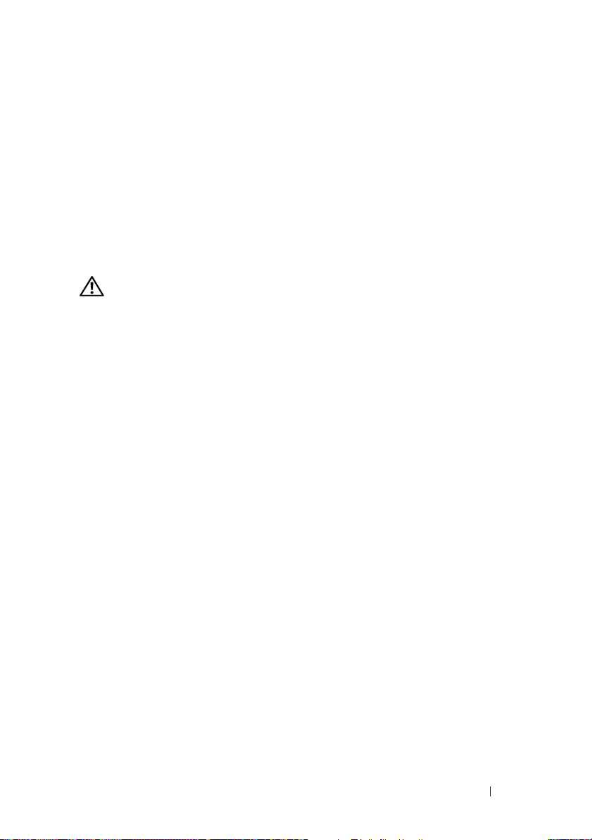
Connect the CMC and KVM Modules
Connect the serial cable and network cable from the management system to
the CMC module. If a second, optional CMC module is installed, connect it
as well. (If your chassis was shipped with M805 or M905 blades pre-installed,
the included CMC firmware will be version 1.2 or greater.)
Connect the keyboard, mouse, and monitor to the optional iKVM module.
Connect the System to Power
Connect the system’s power cables to the system power supplies.
NOTICE: To prevent the power cables from being disconnected accidentally,
use the plastic clip on each power supply to secure the power cable to the power
supply, and use the Velcro strap to secure the cable to the strain-relief bar.
Next, plug the other end of the power cables into a separate power source
such as an uninterruptible power supply (UPS) or a power distribution unit
(PDU).
12 Getting Started With Your System
Page 15

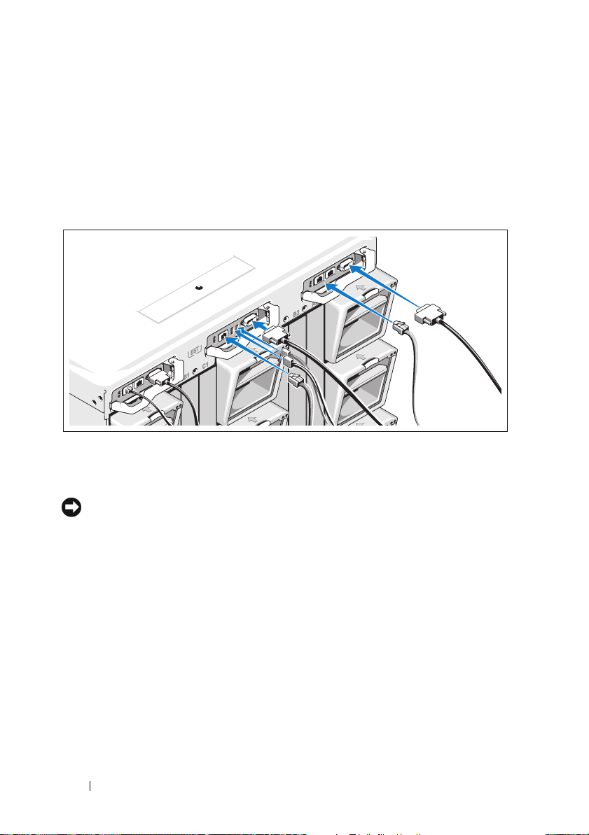
Turn on the System
Press the power button on the enclosure. The power indicator should light.
Getting Started With Your System 13
Page 16
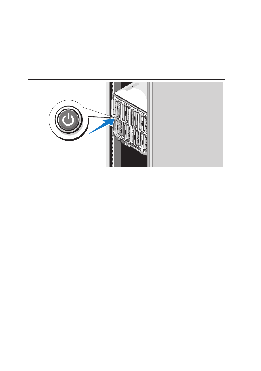
Turn on the Blades
Press the power button on each blade, or power on the blades using
the systems management software.
Complete the 0perating System Setup
If you purchased a preinstalled operating system, see the operating system
documentation that ships with your system. To install an operating system for
the first time, see the Quick Installation Guide. Be sure the operating system
is installed before installing hardware or software not purchased with the
system.
14 Getting Started With Your System
Page 17

Technical Specifications
Blade Specifications
Processor
Processor type
PowerEdge M905
PowerEdge M805
PowerEdge M600
PowerEdge M605
Memory
Architecture
PowerEdge M600
PowerEdge M905, M805, M605
Memory module sockets
PowerEdge M905
PowerEdge M805
PowerEdge M605, M600
Memory module capacities 512 MB (PowerEdge M605 and M600),
Minimum RAM Two memory modules per processor
PowerEdge M905
PowerEdge M805
PowerEdge M600, M605
Four dual-core or quad-core AMD
Opteron 8000 Series processors
Two dual-core or quad-core AMD
Opteron 2000 Series processors
One or two dual-core or quad-core Intel
Xeon processors
One or two dual-core or quad-core AMD
Opteron 2000 Series processors
FBD memory modules, rated for
677-MHz operation
DDR2 memory modules, rated for
677-MHz operation
24 240-pin sockets
16 240-pin sockets
Eight 240-pin sockets
1 GB, 2 GB, 4 GB, or 8 GB
8 GB (Eight 1-GB memory modules)
4 GB (Four 1-GB memory modules)
1 GB (two 512-MB memory modules)
Getting Started With Your System 15
Page 18

Memory
Maximum RAM
PowerEdge M905
PowerEdge M805
PowerEdge M600, M605
Drives
Hard Drives
PowerEdge M805, M905 One or two 2.5-inch SAS hard drives
PowerEdge M600, M605
SATA configuration
SAS configuration
192 GB
128 GB
64 GB
One or two 2.5-inch SATA hard drives
One or two 2.5-inch SAS hard drives
NOTE: SAS and SATA hard drives cannot
be mixed within a M600 or M605 blade.
Connectors
External
USB
PowerEdge M805, M905
PowerEdge M600, M605
Internal
SD Card (PowerEdge M805, M905) One SD card connector
Three 4-pin, USB 2.0 compliant
Two 4-pin, USB 2.0 compliant
Ethernet Controllers
Chipset
PowerEdge M805, M905
PowerEdge M600, M605
16 Getting Started With Your System
Four Ethernet ports with TOE and iSCSI
boot support, provided by two integrated
dual-port Broadcom 5709S Ethernet
controllers
Two Ethernet ports with TOE and iSCSI
boot support, provided by two integrated
Broadcom 5708S controllers
Page 19

Video Controller
Video type ATI RN50 video controller
Video memory 32 MB
Physical
PowerEdge M905, M805
Height
Width
Depth
Weight (maximum configuration)
PowerEdge M605, M600
Height
Width
Depth
Weight (maximum configuration)
Battery
Blade battery CR 2032 3.0-V lithium ion coin cell
38.5cm (15.2 in)
5 cm (2 in)
48.6 cm (19.2 in)
11.1 kg (24.5 lb)
18.9 cm (7.4 in)
5 cm (2 in)
48.6 cm (19.2 in)
5.2-6.4 kg (11.5-14.0 lb)
System Enclosure Specifications
Physical
Height 44.0 cm (17.3 in)
Width 44.7 cm (17.6 in)
Depth 75.5 cm (29.7 in)
Weight (maximum configuration) 178.3 kg (392.2 lb)
Weight (empty) 44.6 kg (98.1 lb)
Getting Started With Your System 17
Page 20

Power Supply Module
AC/DC power supply (per power supply)
Wa t ta g e
Connector
Heat dissipation
Maximum inrush current
System Voltage Requirements
Optional Avocent iKVM Module
Rear externally accessible connectors
USB
ACI port
Video
Chassis Management Controller Module
Externally accessible connectors
Remote management
Serial
Video
Battery CR 2032 3.0-V lithium ion coin cell
SD Card One dedicated internal SD (Secure
2360 W
NEMA C20 receptacle
1205 BTU/hr. maximum
Under typical line conditions and over the
entire system ambient operating range,
the inrush current may reach 55 A per
power supply for 10 ms or less.
200 - 240V, 16A, 3-Phase, 50 /60Hz
200 - 240V, 40.5A, Single Phase, 50 /60Hz
Two 4-pin, USB 2.0-compliant connectors
for keyboard and mouse support
RJ-45
15-pin VGA
Two dedicated 10/100/1000 Mb RJ-45
ports for integrated Ethernet remote
access controller.
9-pin, DTE, 16550-compatible
15-pin VGA
Digital) flash card memory slot for
FlexAddress support.
18 Getting Started With Your System
Page 21

Enclosure Control Panel
Externally accessible connectors
USB
PowerEdge M905, M805 Three 4-pin, USB 2.0-compliant
connectors for keyboard and mouse
support
PowerEdge M605, M600
Video
Navigation Panel
Fea tu re s
Two 4-pin, USB 2.0-compliant connectors
for keyboard and mouse support
15-pin VGA
Four cursor-control keys, one select key,
LCD screen
I/O Module Specifications
PowerConnect M6220 Ethernet Switch Module
Externally accessible connectors
10/100/1000 Mbps Ethernet
Serial
Optional Modules
Four autonegotiating RJ-45 ports
One 4-pin, USB 2.0 type A connector.
(Use provided USB type A to DB9 adapter
to connect to terminal)
Two option bays. Each bay supports a
module with two 24-Gb stacking ports,
two 10-Gb CX4 copper uplinks, or two
10-Gb optical XFPs.
Cisco M7000E Infiniband Switch Module
Externally accessible connectors Eight DDR Infiniband uplink ports
Gb Ethernet Pass-Through Module
Externally accessible connectors Sixteen RJ-45
Getting Started With Your System 19
Ethernet
ports
Page 22

Fibre Channel Pass-Through Module
Externally accessible connectors
Fibre Channel transceiver
Brocade Fibre Channel Switch Module
Externally accessible connectors
Fibre Channel
Serial Port
Environmental
Sixteen external SFP ports that support
1/2/4-Gbps FC speeds
Eight physical FC ports (four enabled by
default, upgradeable to eight) supporting
1/2/4-Gbps Fibre Channel connections
RJ-45
NOTE: For additional information about environmental measurements for specific
system configurations, see dell.com/environmental_datasheets. The system is not for
use in an office environment.
Temperature
Operating
10° to 35°C (50° to 95°F)
NOTE: Decrease the maximum
temperature by 1°C (1.8°F) per 300 m (985 ft)
above 900 m (2955 ft).
Storage
Relative humidity
Operating
Storage
Maximum vibration
Operating
Storage
–40° to 65°C (–40° to 149°F)
8% to 85% (noncondensing) with a
maximum humidity gradation of 10% per
hour
5% to 95% (noncondensing)
0.26 Grms at 10–350 Hz for 15 min
1.54 Grms at 10–250 Hz for 15 min
20 Getting Started With Your System
Page 23

Environmental (continued)
Maximum shock
Operating
Storage
PowerEdge M905, M805
PowerEdge M605, M600
Altitude
Operating
Storage
One shock pulse in the positive z axis of
31 G for up to 2.6 ms
Six consecutively-executed shock pulses
in the positive and negative x, y, and z axis
of 71 G up to 2 ms
Six consecutively-executed shock pulses
in the positive and negative x, y, and z axis
of 71 G up to 2 ms
–16 to 3048 m (–50 to 10,000 ft)
–16 to 10,600 m (–50 to 35,000 ft)
Getting Started With Your System 21
Page 24

22 Getting Started With Your System
Page 25

Dell™ PowerEdge™
M905, M805, M605 a M600
Začínáme se
systémem
Page 26

Poznámky a upozornění
POZNÁMKA: POZNÁMKA označuje důležitou informaci, s jejíž pomocí
lépe využijete svůj počítač.
UPOZORNĚNÍ: UPOZORNĚNÍ poukazuje na možnost poškození
hardwaru nebo ztráty dat a poskytuje návod, jak se danému problému
vyhnout.
POZOR: VÝSTRAHA označuje hrozící nebezpečí poškození majetku,
poranění nebo usmrcení osob.
____________________
Informace obsažené v tomto dokumentu podléhají změnám bez předchozího upozornění.
© 2008 Dell Inc. Všechna práva vyhrazena.
Reprodukce jakýmkoli způsobem bez písemného povolení společnosti Dell Inc. je přísně zakázána.
Ochranné známky použité v tomto textu: Dell, logo DELL a Dell OpenManage jsou ochranné známky
společnosti Dell Inc. Microsoft, Windows a Windows Server jsou ochranné známky nebo registrované
ochranné známky společnosti Microsoft Corporation v USA a dalších zemích. AMD a AMD Opteron
jsou ochranné známky společnosti Advanced Micro Devices, Inc. Intel a Xeon jsou registrované
ochranné známky společnosti Intel Corporation. SUSE je registrovaná ochranná známka společnosti
Novell, Inc. Red Hat a Enterprise Linux jsou registrované ochranné známky společnosti Red Hat, Inc.
VMware je registrovaná ochranná známka společnosti VMware, Inc. v USA a dalších zemích.
V tomto dokumentu mohou být použity další ochranné známky a obchodní názvy buď s odkazem na
právnické osoby a organizace, které uplatňují na dané ochranné známky a obchodní názvy nárok, nebo
s odkazem na jejich výrobky. Společnost Dell Inc. nemá vlastnické zájmy vůči ochranným známkám
a obchodním názvům jiným než svým vlastním.
Model BMX01
Květen 2008 Č. dílu R431C Rev. A00
Page 27

Systémové funkce
V této části jsou popsány hlavní hardwarové a softwarové funkce systému. Jsou
v ní obsaženy i informace o doplňujících dokumentech, které můžete potřebovat
při instalaci systému, a informace k odborné pomoci.
Funkce šasi systému
Šasi systému M1000e má následující funkce:
Rozšiřitelnost
•
Podpora až pro 16 modulů blade (serverových modulů) o poloviční výšce
nebo 8 modulů o plné výšce.
•
Podpora pro tři vrstvy vstupně-výstupních kabeláží, přičemž lze volit mezi
kombinacemi modulů Ethernet, Infiniband a Fibre Channel.
Do šasi lze nainstalovat až šest vstupně-výstupních modulů. Volit lze mezi
přepínači a průchozími moduly Fibre Channel, přepínači Infiniband a
přepínači a průchozími moduly Ethernet.
Spolehlivost
•
Devět záložních modulů systémových ventilátorů vyměnitelných za provozu.
•
Tři 2360wattové zdroje napájení vyměnitelné za provozu a tři záslepky
napájení nebo šest 2360wattových zdrojů napájení vyměnitelných za
provozu. (Tři zdroje napájení poskytují energii systému; další tři zdroje
napájení zajišt’ují redundanci 3+3.)
UPOZORNĚNÍ: Zdroje napájení lze připojit pouze k jednotce rozvaděče
(PDU). Nelze je připojit přímo k elektrické zásuvce.
UPOZORNĚNÍ: Šasi systému vyžaduje zdroj napájení 200–240 V.
Začínáme se systémem 25
Page 28

Funkce pro správu systému
•
Ovladač řízení šasi (CMC) poskytuje několik důležitých funkcí pro správu
systému:
–
Řízení napájení a chlazení na úrovni šasi:
•
Ovladač CMC sleduje požadavky na napájení systému a podporuje
volitelný režim dynamického zapojování zdrojů napájení (DPSE),
takže ovladač CMC může zdroje napájení dynamicky zapínat nebo
přepínat do pohotovostního režimu podle zatížení systému a
požadavků na redundanci. Tím se zvyšuje efektivita napájení.
•
Ovladač CMC hlásí spotřebu energie v reálném čase.
•
Ovladač CMC podporuje volitelnou stropní hodnotu napájení,
při jejímž dosažení se zobrazí výstraha nebo se spustí akce, které
spotřebu energie sníží pod nastavenou hodnotu.
•
Ovladač CMC sleduje a řídí ventilátory na základě skutečně
naměřených okolních a vnitřních teplot.
–
Ovladač CMC poskytuje široké spektrum funkcí pro inventarizaci šasi
a hlášení stavu a chyb.
–
Ovladač CMC umožňuje centralizovanou konfiguraci následujících
nastavení:
•
nastavení sítě a zabezpečení pro ovladač CMC,
•
nastavení redundance napájení a stropní hodnoty napájení,
•
nastavení sítě pro vstupně-výstupní přepínače a ovladač iDRAC,
•
nastavení prvního spouštěného zařízení v modulech blade.
–
Ovladač CMC kontroluje konzistenci vstupně-výstupní kabeláže u
vstupně-výstupních modulů a modulů blade a v případě potřeby některé
systémové komponenty deaktivuje, aby nedošlo k poškození hardwaru.
–
Zabezpečení uživatelského přístupu.
–
Slot pro karty SD na kartě ovladače CMC podporuje volitelnou funkci
stálých názvů WWN a adres MAC, která umožňuje použít pro moduly
blade názvy WWN a adresy MAC založené na slotu. Tím se
zjednodušuje instalování a nahrazování modulů blade.
26 Začínáme se systémem
Page 29

Ovladač CMC má dva porty Ethernet. Port Gb1 slouží k připojení k externí
síti správy. Port Stack umožňuje řetězové propojení s ovladači CMC v
sousedních šasi. Přepínač Ethernet s 24 porty zajišt’uje interní komunikaci
rychlostí 100 Mb/s s moduly blade, vstupně-výstupními moduly, volitelným
modulem iKVM a volitelným druhým (záložním) ovladačem CMC.
Poskytuje také připojení k externí síti správy rychlostí 10, 100 nebo
1000 Mb/s.
POZNÁMKA: Přepínač Ethernet s 24 porty je vyhrazen pro interní
komunikaci mezi ovladačem iDRAC v modulech blade a ovladačem
CMC a následnou komunikaci ovladače CMC s externí sítí správy.
V zájmu redundance je možné nainstalovat druhý, volitelný ovladač CMC,
který bude aktivován za provozu při selhání primárního ovladače.
•
Ovládací panel na šasi zahrnuje displej LCD, který poskytuje aktuální
informace o infrastruktuře a modulech blade a hlásí chyby.
•
Volitelný modul Avocent iKVM (integrated Keyboard, Video and Mouse) má
následující funkce:
–
Modul iKVM spravuje připojení ke všem modulům blade (přepíná
vstupy z jednotlivých modulů blade).
–
Lokální přístup prostřednictvím modulu iKVM lze pro jednotlivé
moduly blade vzdáleně zakázat pomocí uživatelského rozhraní ovladače
iDRAC.
–
Jeden konektor VGA.
–
Dva porty USB pro připojení klávesnice a myši.
POZNÁMKA: Funkčnost sběrnice USB je závislá na připojení
grafického rozhraní, například kabelu monitoru.
–
Port RJ-45 ACI pro vrstvení s externími analogovými moduly Dell a
Avocent KVM a KVM přes IP s porty ARI. Připojení ACI má přednost
před porty KVM na zadním panelu.
–
K modulu iKVM lze získat přístup také z ovládacího panelu v přední
části šasi. Podporováno je fungování buď předního, nebo zadního
modulu KVM (simultánní fungování podporováno není).
POZNÁMKA: Pokud existuje propojení mezi předními a zadními
porty iKVM, je ve výchozím nastavení povolen přední modul iKVM.
Přístup pomocí předního modulu iKVM lze zakázat v uživatelském
rozhraní ovladače CMC.
Začínáme se systémem 27
Page 30

Funkce modulů blade
Výkon
PowerEdge M905
•
Čtyři dvoujádrové nebo čtyřjádrové procesory řady AMD™ Opteron™ 8000.
•
Minimálně 8 GB paměti skládající se z pamět’ových modulů DDR2
pracujících s frekvencí 677 MHz. Pamět’ lze rozšířit až na 192 GB instalací
párů modulů o kapacitě 1 GB, 2 GB, 4 GB nebo 8 GB do 24 soketů pro
pamět’ové moduly na systémové desce modulu blade. Modul blade také
podporuje šetření paměti, pokud je osm nebo šestnáct soketů pro pamět’ové
moduly zaplněno totožnými pamět’ovými moduly.
•
Slot pro kartu SD (Secure Digital) pro podporu vestavěného hypervisoru.
PowerEdge M805
•
Dva dvoujádrové nebo čtyřjádrové procesory řady AMD Opteron 2000.
•
Minimálně 4 GB paměti skládající se z pamět’ových modulů DDR2
pracujících s frekvencí 677 MHz. Pamět’ lze rozšířit až na 128 GB instalací
párů modulů o kapacitě 1 GB, 2 GB, 4 GB nebo 8 GB do 16 soketů pro
pamět’ové moduly na systémové desce modulu blade. Modul blade také
podporuje šetření paměti, pokud je osm nebo šestnáct soketů pro pamět’ové
moduly zaplněno totožnými pamět’ovými moduly.
•
Slot pro kartu SD pro podporu vestavěného hypervisoru.
PowerEdge M600
•
Jeden nebo dva dvoujádrové nebo čtyřjádrové procesory Intel® Xeon®.
•
Minimálně 1 GB paměti skládající se z pamět’ových modulů FBD
pracujících s frekvencí 677 MHz. Pamět’ lze rozšířit až na 64 GB instalací
párů modulů o kapacitě 512 MB, 1 GB, 2 GB, 4 GB nebo 8 GB do osmi
soketů pro pamět’ové moduly na systémové desce modulu blade. Modul
blade také podporuje šetření paměti nebo zrcadlení paměti, pokud je všech
osm soketů pro pamět’ové moduly zaplněno totožnými pamět’ovými
moduly.
28 Začínáme se systémem
Page 31

PowerEdge M605
•
Jeden nebo dva dvoujádrové nebo čtyřjádrové procesory řady AMD
Opteron 2000.
•
Minimálně 1 GB paměti skládající se z pamět’ových modulů DDR2
pracujících s frekvencí 677 nebo 800 MHz. Pamět’ lze rozšířit až na 64 GB
instalací párů modulů o kapacitě 512 MB, 1 GB, 2 GB, 4 GB nebo 8 GB do
osmi soketů pro pamět’ové moduly na systémové desce modulu blade.
Modul blade také podporuje šetření paměti.
Spoleèné funkce
•
Moduly blade PowerEdge M805 a M905 podporují jeden nebo dva
2,5 palcové pevné disky SAS.
•
Moduly blade PowerEdge M600 a M605 podporují jeden nebo dva
2,5 palcové pevné disky SATA
nebo
jeden nebo dva 2,5palcové pevné
disky SAS.
POZNÁMKA: Pevné disky SAS a SATA nelze v rámci modulu blade
kombinovat.
Připojitelnost pevných disků za provozu je podporována, pokud je v modulu
blade nainstalována volitelná karta řadiče RAID.
•
Tři porty USB 2.0 (PowerEdge M805 a M905) nebo dva porty USB 2.0
(PowerEdge M605 a M600) podporují zařízení, jako jsou myš, klávesnice,
jednotka flash, disketová jednotka nebo optická jednotka.
POZNÁMKA: Podporována jsou pouze zařízení USB dodávaná
společností Dell.
•
Integrovaný grafický subsystém VGA s grafickou kartou ATI RN50.
Tento grafický subsystém disponuje 32 MB grafické paměti SDRAM
(bez možnosti rozšíření). Maximální rozlišení je 1280 x 1024 x 65 000 barev
(neprokládané).
•
Ovladač iDRAC (integrated Dell Remote Access Controller) poskytuje
vzdálenou správu systémů, řízení napájení modulů blade, podporu
virtuálních modulů KVM a virtuálních médií, vzdálené výstrahy a
protokolování událostí.
Začínáme se systémem 29
Page 32

•
Čtyři porty pro 1Gb sít’ Ethernet podporované dvěma integrovanými kartami
Broadcom 5709S se dvěma porty (PowerEdge M805 a M905) nebo dva
porty pro 1Gb sít’ Ethernet podporované dvěma integrovanými kartami
Broadcom 5708S (PowerEdge M600 a M605). Podpora funkce TOE (TCP/IP
Offload Engine) a spouštění prostřednictvím protokolu iSCSI.
Úplný seznam systémových funkcí najdete v části Technické specifikace na
stránce 37.
Systém obsahuje následující software:
•
Program nastavení systému pro rychlé zobrazení a změnu informací o
konfiguraci systému. Další informace o tomto programu naleznete v části
Používání programu nastavení systému v
•
Zlepšené bezpečnostní funkce včetně systémového hesla a hesla pro
Příručce majitele hardwaru
nastavení systému dostupné prostřednictvím programu nastavení systému.
•
Diagnostika systému pro hodnocení součástí systému a zařízení. Informace
o používání diagnostiky systému naleznete v části Spuštění diagnostiky
systému v
•
Ovladače videa pro zobrazování mnoha populárních aplikací v režimu
Příručce majitele hardwaru
.
vysokého rozlišení.
•
Software a dokumentace pro správu systémů. Software pro správu systémů
se používá ke správě a monitorování každého jednotlivého modulu blade i
systému jako celku včetně všech modulů blade, sít’ových přepínacích
modulů, zdrojů napájení a ventilátorů. Software pro správu systémů spravuje
systém místně i vzdáleně v síti. Společnost Dell doporučuje používat
software pro správu systémů dodávaný s tímto systémem.
•
Software volitelných řešení pro web-hosting, ukládání do mezipaměti nebo
vyvažování zátěže. Další informace naleznete v dokumentaci k softwaru
řešení.
.
30 Začínáme se systémem
Page 33

Podporované operační systémy
•
Microsoft® Windows Server™ 2003, verze Web, Standard a Enterprise
(32 bitové x86) s aktualizací SP2
•
Microsoft Windows Server 2003, verze Standard, Enterprise a DataCenter
(x64) s aktualizací SP1 nebo SP2
•
Microsoft Windows Server 2003 R2, verze Standard a Enterprise
(32 bitové x86) s aktualizací SP1 nebo SP2
•
Microsoft Windows Server 2003 R2, verze Standard, Enterprise
a DataCenter (x64) s aktualizací SP1 nebo SP2
•
Microsoft Windows Server 2008, verze Standard (s aktualizací SP1
nebo SP2), DataCenter a EM64T
•
Red Hat® Enterprise Linux® AS, ES a WS (verze 4) a EM64T
•
Red Hat Enterprise Linux AS a ES (verze 4) (ia32
•
Red Hat Enterprise Linux Server AS a ES (verze 5) (ia32)
•
Red Hat Enterprise Linux Server AS, ES a WS (verze 5) a EM64T
•
SUSE® Linux Enterprise Server 9 (x86_64) s aktualizací SP3 a EM64T
•
SUSE Linux Enterprise Server 10 (x86_64) a EM64T
•
VMWare® ESX 3.1
•
VMWare ESX 3.5
)
Další užitečné informace
POZOR: Prostudujte si informace o bezpečnosti a předpisech, které
byly dodány se systémem. Informace o záruce je součástí tohoto
dokumentu nebo je přiložena samostatně.
•
Příručka konfigurace
a modulů blade.
•
Návod pro instalaci do stojanu
se stojanovým systémem popisují instalaci systému do stojanu.
•
Příručka majitele hardwaru
popisuje řešení problémů se systémem a instalaci nebo výměnu komponent.
Tento dokument můžete nalézt na disku CD dodaném se systémem nebo na
adrese
support.dell.com
poskytuje informace o konfiguraci šasi systému
nebo
Pokyny pro instalaci do stojanu
obsahuje informace o funkcích systému a
.
Začínáme se systémem 31
dodané
Page 34

•
Příručka uživatele Dell Chassis Management Controller
informace o používání funkcí vzdálené správy systému.
•
Disky CD nebo DVD dodané se systémem obsahují dokumentaci a nástroje
pro konfiguraci a správu systému.
•
Dokumentace k softwaru pro správu systému popisuje funkce, požadavky,
instalaci a základní operace tohoto softwaru.
•
Dokumentace operačního systému popisuje proces instalace (v nezbytném
případě), konfigurace a používání softwaru operačního systému.
•
Dokumentace k jakýmkoli komponentám zakoupeným samostatně poskytuje
informace o konfiguraci a instalaci těchto komponent.
•
Se systémem jsou někdy dodány také aktualizace, které popisují změny v
systému, softwaru nebo dokumentaci.
POZNÁMKA: Vždy nejprve zkontrolujte a pročtěte aktualizace
uvedené na adrese support.dell.com, protože tyto aktualizace často
nahrazují informace v ostatních dokumentech.
•
Součástí dodávky mohou být také poznámky k verzi nebo soubory readme,
které obsahují poslední aktualizace k systému nebo dokumentaci, případně
rozšířené technické materiály určené zkušeným uživatelům a technikům.
poskytuje podrobné
Odborná pomoc
Nerozumíte-li některému z postupů popsaných v této příručce nebo nepracuje-li
systém podle očekávání, nahlédněte do
Společnosti Dell rovněž nabízí školení a certifikaci (Dell Enterprise Training and
Certification). Další informace najdete na adrese
nemusí být nabízena ve všech regionech.
Příručky majitele hardwaru
dell.com/training
.
. Tato služba
32 Začínáme se systémem
Page 35

Instalace a konfigurace
POZOR: Před provedením následujícího postupu si pročtěte
bezpečnostní pokyny a důležité informace o plnění norem, které byly
dodány se systémem, a postupujte podle těchto pokynů a informací.
Další informace o doporučených bezpečnostních opatřeních najdete
na adrese www.dell.com/regulatory_compliance.
V této části jsou popsány kroky, které je nutné provést při první instalaci systému.
Rozbalení systému
Rozbalte systém a identifikujte jeho jednotlivé součásti. Veškerý obalový materiál
uschovejte pro případ pozdější potřeby.
Instalace systému do stojanu
Nejprve si přečtěte Bezpečnostní pokyny uvedené v dokumentaci k instalaci do
stojanu a potom proveďte instalaci systému do stojanu.
Pokyny k instalaci systému do stojanu naleznete v dokumentaci k instalaci do
stojanu. Pokyny k napájení a chlazení najdete v nástroji pro plánování kapacity
stojanu na adrese
www.dell.com
.
Začínáme se systémem 33
Page 36

Instalace modulů blade
Postupujte zleva doprava a shora dolů a zasouvejte moduly do šasi. Jakmile bude
modul blade bezpečně nainstalován, držadlo se vrátí do zamčené pozice.
Připojení ovladače CMC a modulů KVM
Připojte sériový kabel a sít’ový kabel z řídícího systému k modulu ovladače CMC.
Připojte také druhý, volitelný modul ovladače CMC (pokud je nainstalován).
(Pokud bylo šasi dodáno s předinstalovanými moduly blade M805 nebo M905,
bude zahrnut firmware CMC verze 1.2 nebo vyšší.)
Připojte klávesnici, myš a monitor k volitelnému modulu iKVM.
34 Začínáme se systémem
Page 37

Připojení systému k napájení
Připojte napájecí kabely systému ke zdrojům napájení.
UPOZORNĚNÍ: Chcete-li zabránit nechtěnému odpojení napájecích
kabelů, připevněte zástrčky napájecích kabelů ke zdrojům napájení pomocí
plastových svorek na zdrojích napájení a pomocí pásky Velcro připevněte
kabel k protideformační tyči.
Poté zasuňte druhý konec napájecích kabelů do odděleného zdroje napájení,
například zdroje UPS (nepřerušitelný zdroj napájení) nebo do jednotky rozvaděče
(PDU).
Zapnutí systému
Stiskněte tlačítko napájení na šasi. Měl by se rozsvítit indikátor napájení.
Začínáme se systémem 35
Page 38

Zapnutí modulů blade
Stiskněte tlačítko napájení na každém modulu blade nebo spust’te napájení
modulů blade pomocí softwaru pro správu systémů.
Dokončení nastavení operačního systému
Pokud jste zakoupili předinstalovaný operační systém, prostudujte dokumentaci k
operačnímu systému dodanou se systémem. Pokyny k první instalaci operačního
systému naleznete v Příručce rychlé instalace. Než začnete s instalací hardwaru či
softwaru, který nebyl zakoupen společně se systémem, ujistěte se, že je
nainstalován operační systém.
36 Začínáme se systémem
Page 39

Technické specifikace
Specifikace modulù blade
Procesor
Typ procesoru
PowerEdge M905 Čtyři dvoujádrové nebo čtyřjádrové
procesory řady AMD Opteron 8000
PowerEdge M805 Dva dvoujádrové nebo čtyřjádrové
procesory řady AMD Opteron 2000
PowerEdge M600 Jeden nebo dva dvoujádrové nebo
čtyřjádrové procesory Intel Xeon
PowerEdge M605 Jeden nebo dva dvoujádrové nebo
čtyřjádrové procesory řady AMD
Opteron 2000
Pamět’
Architektura
PowerEdge M600 Pamět’ové moduly FBD s taktovací
frekvencí 677 MHz
PowerEdge M905, M805, M605 Pamět’ové moduly DDR2 s taktovací
frekvencí 677 MHz
Sokety pro pamět’ové moduly
PowerEdge M905 24 240kolíkových soketů
PowerEdge M805 16 240kolíkových soketů
PowerEdge M605, M600 Osm 240kolíkových soketů
Kapacity pamět’ových modulů 512 MB (PowerEdge M605 a M600), 1 GB,
2 GB, 4 GB nebo 8 GB
Minimum paměti RAM Dva pamět’ové moduly na každý procesor
PowerEdge M905 8 GB (osm pamět’ových modulů
s kapacitou 1 GB)
PowerEdge M805 4 GB (čtyři pamět’ové moduly
skapacitou1GB)
PowerEdge M600, M605 1 GB (dva pamět’ové moduly
s kapacitou 512 MB)
Začínáme se systémem 37
Page 40

Pamět’ (pokračování)
Maximum paměti RAM
PowerEdge M905 192 GB
PowerEdge M805 128 GB
PowerEdge M600, M605 64 GB
Jednotky
Pevné disky
PowerEdge M805, M905 Jeden nebo dva 2,5palcové pevné disky SAS
PowerEdge M600, M605
Konfigurace SATA Jeden nebo dva 2,5palcové pevné disky
SATA
Konfigurace SAS Jeden nebo dva 2,5palcové pevné disky SAS
POZNÁMKA: Pevné disky SAS a
SATA nelze v rámci modulu blade
M600 nebo M605 kombinovat.
Konektory
Externí
USB
PowerEdge M805, M905 Tři 4kolíkové, USB 2.0
PowerEdge M600, M605 Dva 4kolíkové, USB 2.0
Interní
Karta SD (PowerEdge M805, M905) Jeden konektor pro kartu SD
Sít’ové karty Ethernet
Čipová sada
PowerEdge M805, M905 Čtyři porty Ethernet s podporou funkce TOE
a spouštění prostřednictvím protokolu iSCSI
poskytované dvěma integrovanými kartami
Ethernet Broadcom 5709S se dvěma porty
PowerEdge M600, M605 Dva porty Ethernet s podporou funkce TOE
a spouštění prostřednictvím protokolu iSCSI
poskytované dvěma integrovanými kartami
Broadcom 5708S
38 Začínáme se systémem
Page 41

Grafická karta
Typ grafiky Grafická karta ATI RN50
Grafická pamět’ 32 MB
Rozměry
PowerEdge M905, M805
Výška 38,5 cm
Šířka 5 cm
Hloubka 48,6 cm
Hmotnost (maximální konfigurace) 11,1 kg
PowerEdge M605, M600
Výška 18,9 cm
Šířka 5 cm
Hloubka 48,6 cm
Hmotnost (maximální konfigurace) 5,2–6,4 kg
Baterie
Baterie modulu blade Lithium-iontová knoflíková baterie
CR 2032 3,0 V
Specifikace šasi systému
Rozměry
Výška 44,0 cm
Šířka 44,7 cm
Hloubka 75,5 cm
Hmotnost (maximální konfigurace) 178,3 kg
Hmotnost (prázdné) 44,6 kg
Začínáme se systémem 39
Page 42

Modul zdroje napájení
Střídavý/stejnosměrný proud (na jeden zdroj napájení)
Výkon 2360 W
Konektor Zásuvka NEMA C20
Odvod tepla 1205
Maximální nárazový proud V typických podmínkách napájení a v celém
Požadavky na napájení systému
Volitelný modul Avocent iKVM
Zadní externě přístupné konektory
USB Dva 4kolíkové konektory USB 2.0 pro
Port ACI RJ-45
Video 15kolíkový VGA
Modul ovladače CMC (Chassis Management Controller)
Externě přístupné konektory
Vzdálená správa
Sériový
Video
Baterie Lithium-iontová knoflíková baterie
Karta SD Jeden vyhrazený interní slot pro pamět’ovou
BTU/hod. (maximum)
provozním rozsahu systému může nárazový
proud dosáhnout 55 A na jeden napájecí
zdroj po dobu 10 ms nebo méně.
2
00–240 V, 16 A, třífázové napájení,
50/60 Hz
200–240 V, 40,5 A, jednofázové napájení,
50/60 Hz
klávesnici a myš
Dva vyhrazené porty RJ-45 s přenosovou
rychlostí 10/100/1000 Mb/s pro integrovaný
ovladač vzdáleného přístupu Ethernet
9kolíkový, DTE, kompatibilní
s normou 16550
15kolíkový VGA
CR 2032 3,0 V
kartu SD (Secure Digital) pro podporu
funkce FlexAddress
40 Začínáme se systémem
Page 43

Ovládací panel na šasi
Externě přístupné konektory
USB
PowerEdge M905, M805
PowerEdge M605, M600
Video 15kolíkový VGA
Navigační panel
Funkce
Tři 4kolíkové konektory USB 2.0 pro
klávesnici a myš
Dva 4kolíkové konektory USB 2.0 pro
klávesnici a myš
Čtyři kurzorové ovládací klávesy, jedna
klávesa pro výběr, obrazovka LCD
Specifikace vstupně-výstupního modulu
Modul přepínače Ethernet PowerConnect M6220
Externě přístupné konektory
Ethernet 10/100/1000 Mb/s Čtyři porty RJ-45 s automatickým
vyjednáváním
Sériový Jeden 4kolíkový konektor USB 2.0 typu A
(pro připojení k terminálu je třeba použít
dodaný adaptér z USB typu A na DB9)
Volitelné moduly Dvě pozice pro volitelné moduly. Každá
pozice podporuje modul se dvěma
stohovacími porty 24 Gb, dvěma měděnými
přenosovými porty CX4 10 Gb nebo dvěma
optickými vysílači XFP 10 Gb.
Modul přepínače Infiniband Cisco M7000E
Externě přístupné konektory
Osm přenosových portů Infiniband DDR
Začínáme se systémem 41
Page 44

Průchozí modul Gb Ethernet
Externě přístupné konektory
Průchozí modul Fibre Channel
Externě přístupné konektory
Vysílač Fibre Channel Šestnáct externích portů SFP podporujících
Modul přepínače Fibre Channel Brocade
Externě přístupné konektory
Fibre Channel Osm fyzických portů FC (ve výchozím
Sériový port RJ-45
Prostředí
Šestnáct portů RJ-45 pro sít’ Ethernet
rychlosti 1/2/4 Gb/s
nastavení jsou povoleny čtyři, lze rozšířit na
osm) podporujících připojení Fibre Channel
rychlostí 1/2/4 Gb/s
POZNÁMKA: Další informace o měřených údajích prostředí najdete pro
jednotlivé systémové konfigurace na adrese
dell.com/environmental_datasheets. Systém není určen pro použití v
kanceláři.
Teplota
Provozní 10 až 35 °C
POZNÁMKA: Snižte nejvyšší teplotu
o 1 °C na každých 300 m nad
nadmořskou výškou 900 m.
Skladovací -40 až 65 °C
Relativní vlhkost
Provozní 8 až 85 % (bez kondenzace) s maximálním
nárůstem vlhkosti o 10 % za hodinu
Skladovací 5 až 95 % (bez kondenzace)
Maximální vibrace
Provozní 0,26 g při 10–350 Hz po dobu 15 minut
Skladovací 1,54 g při 10–250 Hz po dobu 15 minut
42 Začínáme se systémem
Page 45

Prostředí (pokračování)
Maximální ráz
Provozní Jeden rázový impuls v kladné ose z o síle
31 G v délce do 2,6 ms
Skladovací
PowerEdge M905, M805
PowerEdge M605, M600
Nadmořská výška
Provozní -16 až 3 048 m
Skladovací -16 až 10 600 m
Šest po sobě jdoucích rázových impulsů v
kladné i záporné ose x, y, a z o síle 71 G v
délce do 2 ms
Šest po sobě jdoucích rázových impulsů v
kladné i záporné ose x, y, a z o síle 71 G v
délce do 2 ms
Začínáme se systémem 43
Page 46

44 Začínáme se systémem
Page 47

Systèmes Dell™ PowerEdge™
M905, M805, M605 et M600
Guide de mise en route
Page 48

Remarques, avis et précautions
REMARQUE : Une REMARQUE indique des informations importantes qui peuvent
vous aider à mieux utiliser votre ordinateur.
AVIS : Un AVIS vous avertit d'un risque de dommage matériel ou de perte
de données et vous indique comment éviter le problème.
PRÉCAUTION : Une PRÉCAUTION indique un risque potentiel d'endommagement
du matériel, de blessure corporelle ou de mort.
____________________
Les informations contenues dans ce document peuvent être modifiées sans préavis.
© 2008 Dell Inc. Tous droits réservés.
La reproduction de ce document de quelque manière que ce soit sans l'autorisation écrite de Dell Inc.
est strictement interdite.
Marques mentionnées dans ce document : Dell, le logo DELL et Dell OpenManage sont des marques
déposées de Dell Inc. ; Microsoft, Windows et Windows Server sont des marques ou des marques
déposées de Microsoft Corporation aux États-Unis et/ou dans d'autres pays ; AMD et AMD Opteron
sont des marques déposées d'Advanced Micro Devices, Inc. ; Intel et Xeon sont des marques déposées
d'Intel Corporation ; SUSE est une marque déposée de Novell, Inc. ; Red Hat et Enterprise Linux sont
des marques déposées de Red Hat, Inc. ; VMware est une marque déposée de VMware, Inc. aux ÉtatsUnis et/ou dans d'autres pays.
Tous les autres noms de marques et marques commerciales utilisés dans ce document se rapportent
aux sociétés propriétaires des marques et des noms de ces produits. Dell Inc. dénie tout intérêt
propriétaire vis-à-vis des marques et des noms de marque autres que les siens.
Modèle BMX01
Mai 2008 N/P R431C Rév. A00
Page 49

Caractéristiques du système
Cette section décrit les principales caractéristiques matérielles et logicielles
du système. Elle contient également des informations relatives à d'autres
documents pouvant être utiles à la configuration du système et indique
comment obtenir une assistance technique.
Caractéristiques du châssis
Le châssis du système M1000e présente les caractéristiques suivantes :
Evolutivité
• Prise en charge d'un maximum de 16 lames de mi-hauteur ou de 8 lames
de hauteur normale (modules du serveur).
• Prise en charge de trois couches d'E/S pouvant comprendre diverses
combinaisons de modules Ethernet, Infiniband et Fibre Channel.
Le châssis peut accueillir jusqu'à six modules d'E/S (commutateurs ou
modules d'intercommunication Fibre Channel ou Ethernet, et
commutateurs Infiniband).
Fiabilité
• Neuf modules de ventilation redondants et enfichables à chaud.
• Trois blocs d'alimentation enfichables à chaud de 2360 watts et trois
caches d'alimentation ou six blocs d'alimentation enfichables à chaud
de 2360 watts. Les trois premiers blocs alimentent le système et les trois
blocs supplémentaires sont redondants.
AVIS : Les blocs d'alimentation ne peuvent être reliés qu'à une unité de distribution
de l'alimentation (PDU). Ils ne peuvent pas être branchés directement sur une prise
secteur.
AVIS : Le châssis nécessite une source d'alimentation de 200-240 V.
Guide de mise en route 47
Page 50

Gestion des systèmes
• Contrôleur CMC (Chassis Management Controller) fournissant plusieurs
fonctions essentielles de gestion des systèmes :
– Gestion de l'alimentation et des températures au niveau du châssis :
• Le contrôleur CMC surveille les besoins en alimentation du
système et prend en charge l'utilisation du mode DPSE (Dynamic
Power Supply Engagement) fourni en option. Il peut ainsi
améliorer la gestion de l'alimentation en activant les blocs
d'alimentation ou en les mettant en veille en fonction des besoins
constatés en termes de charge de travail et de redondance.
• Le contrôleur CMC fournit des informations en temps réel sur
la consommation électrique.
• Le contrôleur CMC prend en charge la définition d'un seuil
d'alimentation (en option) qui permet de générer une alerte ou de
déclencher certaines actions visant à maintenir la consommation
en dessous d'un niveau donné.
• Le contrôleur CMC surveille le fonctionnement des ventilateurs
en se basant sur la mesure en temps réel des températures
ambiante et interne.
– Le contrôleur CMC permet de bénéficier de fonctions complètes
d'inventaire et de consignation des erreurs ou des états.
– Le contrôleur CMC permet de centraliser la configuration des
paramètres suivants :
• Paramètres réseau et de sécurité du contrôleur CMC
• Redondance de l'alimentation et définition de seuils
• Paramètres réseau des E/S pour les commutateurs et les
contrôleurs DRAC intégrés
• Définition du premier périphérique d'amorçage sur les lames
– Le contrôleur CMC vérifie la cohérence des infrastructures d'E/S
entre les modules d'E/S et les lames. Si nécessaire, il désactive
des composants afin de protéger le matériel du système.
– Sécurité des accès utilisateur.
48 Guide de mise en route
Page 51

– Un emplacement carte mémoire Secure Digital sur la carte CMC
prend en charge une fonction permanente WWN/MAC (en option)
qui permet d'utiliser des WWN/MAC à emplacement pour les lames,
ce qui simplifie leur installation et leur remplacement.
Le contrôleur CMC comprend deux ports Ethernet. Le port “Gb1” est
utilisé pour la connexion au réseau de gestion externe. Le port “Stack”
permet de relier en série les contrôleurs CMC installés dans des châssis
adjacents. Un commutateur Ethernet comprenant 24 ports gère les
communications internes (débit de 100 Mbps) avec les lames, les modules
d'E/S, le module KVM intégré en option et un second contrôleur CMC
redondant disponible en option. Il fournit également une connexion à
10/100/1000 Mbps avec le réseau de gestion externe.
REMARQUE : Le commutateur Ethernet 24 ports est réservé prioritairement
aux communications internes entre le module DRAC intégré aux lames et
le contrôleur CMC, puis au réseau de gestion externe.
Un second contrôleur CMC en option et enfichable à chaud peut être
installé pour fournir une redondance en cas de basculement.
• Le panneau de commande du châssis comprend un écran LCD qui affiche
des informations sur l'infrastructure en cours, les lames et les erreurs
rencontrées.
• Un module KVM intégré (iKVM) en option de marque Avocent offre
les fonctionnalités suivantes :
– Le module iKVM maintient actives les connexions à toutes les lames
tandis que les entrées sont envoyées uniquement à la lame choisie.
– L'accès local au module iKVM peut être désactivé à distance, lame
par lame, via l'interface utilisateur du module DRAC intégré.
– Un connecteur VGA.
– Deux ports USB pour la connexion d'un clavier et d'une souris.
REMARQUE : Les fonctionnalités USB ne peuvent être utilisées que si
une interface vidéo est connectée (câble de moniteur, par exemple).
– Un port RJ-45 ACI permet le couplage avec des commutateurs KVM
analogiques et KVM sur IP de marque Dell et Avocent dotés de ports
ARI. La connexion ACI est prioritaire sur les ports situés sur le
panneau arrière du KVM.
Guide de mise en route 49
Page 52

– Le module KVM intégré est également accessible à partir du panneau
de commande situé à l'avant du châssis. Il est possible d'utiliser le
module KVM situé à l'avant ou à l'arrière, mais pas les deux
simultanément.
REMARQUE : Le module frontal est activé par défaut en cas de conflit entre
les ports situés à l'avant et à l'arrière du module iKVM. L'accès au module
iKVM frontal peut être désactivé via l'interface utilisateur du contrôleur CMC.
Caractéristiques des lames
Performances
PowerEdge M905
• Quatre processeurs AMD™ Opteron™ 8000 Series double cœur ou
quadruple cœur.
• Un minimum de 8 Go constitué de barrettes de mémoire de 677 MHz,
extensible à 192 Go au maximum par l'installation de paires de barrettes
de 1, 2, 4 ou 8 Go dans les 24 emplacements prévus à cet effet sur la carte
système de la lame. Cette lame prend également en charge l'utilisation de
mémoire de réserve si des barrettes de mémoire identiques sont utilisées
dans huit ou seize des emplacements de module de mémoire.
• Un emplacement pour carte mémoire Secure Digital en vue de la prise
en charge de l'Hyperviser intégré.
PowerEdge M805
• Deux processeurs double cœur ou quadruple cœur AMD Opteron
2000 Series.
• Un minimum de 4 Go constitué de barrettes de mémoire DDR2 de
677 MHz, extensible à 128 Go au maximum par l'installation de paires
de barrettes de 1, 2, 4 ou 8 Go dans les 16 emplacements prévus à cet effet
sur la carte système de la lame. Cette lame prend également en charge
l'utilisation de mémoire de réserve si des barrettes de mémoire identiques
sont utilisées dans huit ou seize des sockets prévus à cet effet.
• Un emplacement pour carte mémoire Secure Digital en vue de la prise
en charge de l'Hyperviser intégré.
50 Guide de mise en route
Page 53

PowerEdge M600
• Un ou deux processeurs Intel® Xeon® double cœur ou quadruple cœur
• Un minimum de 1 Go constitué de barrettes de mémoire FBD de
677 MHz, extensible à 64 Go au maximum par l'installion de paires de
barrettes de 512 Mo ou de 1, 2, 4 ou 8 Go dans les huit sockets prévus à cet
effet sur la carte système de la lame. Si les huit emplacements mémoire
contiennent des modules identiques, il est possible d'utiliser une mémoire
de réserve ou une mise en miroir.
PowerEdge M605
• Un ou deux processeurs AMD Opteron 2000 Series double cœur ou
quadruple cœur.
• Un minimum de 1 Go constitué de barrettes de mémoire DDR2 de
677 MHz ou de 800 MHz, extensible à 64 Go au maximum par
l'installation de paires de barrettes de 512 Mo ou de 1, 2, 4 ou 8 Go dans
les huit sockets prévus à cet effet sur la carte système de la lame. Le serveur
lame prend également en charge l'utilisation d'une mémoire de réserve.
Fonctionnalités communes
• Les lames PowerEdge M805 et M905 prennent en charge un ou deux
disques durs SAS de 2,5 pouces.
• Les lames PowerEdge M600 et M605 prennent en charge un ou deux
disques durs SATA de 2,5 pouces
ou
un ou deux disques durs SAS de
2,5 pouces.
REMARQUE : Une lame ne peut pas contenir à la fois des disques durs
de type SAS et SATA.
L'ajout ou le retrait à chaud des disques est pris en charge si une carte
contrôleur RAID en option est installée dans la lame.
• Trois ports compatibles USB 2.0 (PowerEdge M805 et M905) ou deux
ports compatibles USB 2.0 (PowerEdge M605 et M600) assurent la prise
en charge des périphériques suivants : souris, clavier, lecteur flash, lecteur
de disquette et lecteur optique.
REMARQUE : Seuls les périphériques USB fournis par Dell sont pris
en charge.
Guide de mise en route 51
Page 54

• Sous-système vidéo intégré compatible VGA comprenant un contrôleur
vidéo ATI RN50. Ce sous-système vidéo contient 32 Mo de mémoire
vidéo SDRAM (non extensible). La résolution maximale est de
1280x1024x 65000 couleurs (non-entrelacé).
• Contrôleur DRAC intégré (iDRAC, Integrated Dell Remote Access
Controller) fournissant différentes capacités : gestion de systèmes à
distance, gestion de l'alimentation au niveau des lames, prise en charge
des modules KVM et des médias virtuels, déclenchement d'alertes et
consignation d'événements à distance.
• Quatre ports Ethernet de 1 Go pris en charge par deux contrôleurs
Broadcom 5709S intégrés à double port (PowerEdge M805 et M905),
ou deux ports Ethernet de 1 Go pris en charge par deux contrôleurs
Broadcom 5708S intégrés (PowerEdge M600 et M605). Le protocole TOE
(TCP/IP Offload Engine) et l'amorçage iSCSI sont pris en charge.
Pour une liste complète des caractéristiques du système, reportez-vous au
“Spécifications techniques”, page 60.
Les logiciels suivants sont livrés avec le système :
• Programme de configuration du système permettant de consulter et
de modifier rapidement les informations sur la configuration du système.
Pour plus d'informations sur ce programme, voir “Using the System Setup
Program” (Utilisation du programme de configuration du système), dans
le document
Hardware Owner's Manual
(Manuel du propriétaire).
• Fonctions de sécurité avancées (disponibles dans le programme de
configuration du système) permettant de définir un mot de passe système
et un mot de passe de configuration.
• Diagnostics permettant de tester les composants et les périphériques
du système. Pour plus d'informations sur les diagnostics du système,
voir “Running the System Diagnostics” (Exécution des diagnostics
du système), dans le document
Hardware Owner's Manual
(Manuel
du propriétaire).
• Pilotes vidéo permettant d'afficher un grand nombre d'applications très
répandues dans les modes à haute résolution.
52 Guide de mise en route
Page 55

• Logiciel de gestion des systèmes et documentation associée. Les logiciels
de gestion des systèmes permettent de gérer et de surveiller chaque lame
de façon individuelle, mais aussi le système dans son ensemble, en
incluant les lames, les modules de commutation réseau, les blocs d'alimentation et les ventilateurs. Ces logiciels peuvent être utilisés pour gérer le
système localement ou à distance via le réseau. Dell recommande l'utilisation du logiciel de gestion des systèmes fourni avec le système.
• Solutions en option pour l'hébergement Web, la mise en cache ou
l'équilibrage de charge. Pour plus d'informations, consultez la
documentation accompagnant les logiciels.
Systèmes d'exploitation pris en charge
• Microsoft® Windows Server™ 2003 éditions Web, Standard et Enterprise
(32 bits, x86) avec SP2
• Microsoft Windows Server 2003, éditions Standard, Enterprise et
Datacenter (x64) avec SP1 ou SP2
• Microsoft Windows Server 2003 R2 éditions Standard et Enterprise
(32 bits, x86) avec SP1 ou SP2
• Microsoft Windows Server 2003 R2, éditions Standard, Enterprise et
Datacenter (x64) avec SP1 ou SP2
• Microsoft Windows Server 2008, éditions Standard avec SP1 ou SP2,
DataCenter et EM64T
•Red Hat
• Red Hat Enterprise Linux AS et ES (version 4) (ia32
• Red Hat Enterprise Linux Server AS et ES (version 5) (ia32)
• Red Hat Enterprise Linux Server AS, ES et WS (version 5) et EM64T
•SUSE
• SUSE Linux Enterprise Server 10 (x86_64) et EM64T
•VMWare
• VMWare ESX 3.5
®
Enterprise Linux® AS, ES et WS (version 4) et EM64T
)
®
Linux Enterprise Server 9 (x86_64) avec SP3 et EM64T
®
ESX 3.1
Guide de mise en route 53
Page 56

Autres informations utiles
PRÉCAUTION ! Consultez les informations de sécurité et de garantie fournies
avec votre système. Les informations sur la garantie se trouvent soit dans ce
document, soit à part.
•Le
Configuration Guide
sur la configuration du châssis du système et des lames.
• Les documents
Rack Installation Instructions
avec la solution rack décrivent l'installation du système.
• Le document
contient des informations sur les caractéristiques du système, ainsi que des
instructions relatives au dépannage et à l'installation ou au remplacement
de composants. Il se trouve sur les CD fournis avec le système et sur le site
support.dell.com
• Le document
(Contrôleur de gestion de châssis Dell) contient des informations
détaillées sur l'utilisation des fonctions de gestion à distance du système.
• Les CD ou les DVD fournis avec le système contiennent des documents et
des outils relatifs à la configuration et à la gestion du système.
• La documentation relative aux logiciels de gestion du système contient
des informations sur les fonctionnalités, l'installation et l'utilisation
de base de ces logiciels, ainsi que sur la configuration requise.
• La documentation du système d'exploitation indique comment installer
(au besoin), configurer et utiliser le système d'exploitation.
• La documentation fournie avec les composants achetés séparément
indique comment installer et configurer ces options.
• Des mises à jour sont parfois fournies avec le système. Elles décrivent les
modifications apportées au système, aux logiciels ou à la documentation.
Rack Installation Guide
Hardware Owner's Manual
Dell Chassis Management Controller User’s Guide
(Guide de configuration) fournit des informations
(Guide d'installation du rack) et
(Instructions d'installation du rack) fournis
(Manuel du propriétaire)
.
REMARQUE : Vérifiez toujours si des mises à jour sont disponibles sur le site
support.dell.com et lisez-les en premier, car elles remplacent souvent
les informations contenues dans les autres documents.
• Si des notes d'édition ou des fichiers lisez-moi (readme) sont fournis,
ils contiennent des mises à jour de dernière minute apportées au système
ou à la documentation, ou bien des informations techniques destinées aux
utilisateurs expérimentés ou aux techniciens.
54 Guide de mise en route
Page 57

Obtention d'une assistance technique
Si vous ne comprenez pas une procédure décrite dans ce guide ou si le
système ne réagit pas comme prévu, reportez-vous au document Hardware
Owner's Manual (Manuel du propriétaire).
Des formations et certifications Dell Enterprise sont disponibles. Pour plus
d'informations, consultez le site dell.com/training. Ce service n'est disponible
que dans certains pays.
Installation et configuration
PRÉCAUTION ! Avant de commencer la procédure suivante, lisez et respectez
les consignes de sécurité et les informations importantes sur les réglementations
fournies avec le système. Pour plus d'informations sur les meilleures pratiques en
matière de sécurité, voir le site www.dell.com/regulatory_compliance.
Cette section décrit les étapes devant être exécutées lors de la configuration
initiale du système.
Déballage du système
Sortez le système de son emballage et identifiez chaque élément. Conservez
les matériaux d'emballage au cas où vous en auriez besoin ultérieurement.
Installation du système dans un rack
Commencez par lire les consignes de sécurité qui se trouvent dans la
documentation d'installation du rack, puis installez le système dans le rack.
Consultez la documentation d'installation du rack pour obtenir les instructions appropriées. Pour obtenir des directives concernant l'alimentation et
le refroidissement, reportez-vous à l'outil de planification de capacité des
racks disponible sur le site www.dell.com.
Guide de mise en route 55
Page 58

Installation des lames
Insérez les modules dans le châssis en commençant par le haut et en
procédant de gauche à droite. Lorsqu'une lame est correctement installée,
la poignée revient en position fermée.
56 Guide de mise en route
Page 59

Connexion du contrôleur CMC et des modules KVM
Connectez les câbles série et réseau du système de gestion au module CMC.
Si un second module CMC en option est installé, connectez-le également.
Si votre châssis a été fourni avec des lames M805 ou M905 préinstallées,
le micrologiciel CMC inclus est de version 1.2 ou ultérieure.
Connectez le clavier, la souris et le moniteur au module iKVM en option.
Branchement du système sur le secteur
Enfichez les câbles d'alimentation du système dans les blocs d'alimentation.
AVIS : Pour éviter que les câbles d'alimentation ne soient débranchés
accidentellement, utilisez le clip en plastique situé sur chaque bloc d'alimentation
pour fixer le câble. Utilisez également la bande Velcro pour maintenir le câble sur
la barre de retenue.
Branchez ensuite l'autre extrémité des cordons d'alimentation sur une source
d'alimentation autonome, comme un onduleur ou une unité de distribution
de l'alimentation.
Guide de mise en route 57
Page 60

Mise sous tension du système
Appuyez sur le bouton d'alimentation du châssis. Le voyant d'alimentation
doit s'allumer.
58 Guide de mise en route
Page 61

Mise sous tension des lames
Mettez chaque lame sous tension en appuyant sur son bouton d'alimentation
ou en utilisant le logiciel de gestion des systèmes.
Finalisation de l'installation du système d'exploitation
Si vous avez acheté un système d'exploitation préinstallé, consultez tout
d'abord la documentation associée, qui a été fournie avec l'ordinateur. Si vous
installez un système d'exploitation pour la première fois, consultez le
document Quick Installation Guide (Guide d'installation rapide). Veillez à
installer le système d'exploitation avant tout élément matériel ou logiciel
acheté séparément.
Guide de mise en route 59
Page 62

Spécifications techniques
Spécifications des lames
Processeur
Type de processeur
PowerEdge M905
PowerEdge M805
PowerEdge M600
PowerEdge M605
Mémoire
Architecture
PowerEdge M600
PowerEdge M905, M805, M605
Connecteurs mémoire
PowerEdge M905
PowerEdge M805
PowerEdge M605, M600
Capacité des barrettes de mémoire 512 Mo (PowerEdge M605 et M600),
RAM minimale Deux barrettes de mémoire par
PowerEdge M905
PowerEdge M805
PowerEdge M600, M605
Quatre processeurs AMD Opteron 8000
Series double cœur ou quadruple cœur
Deux processeurs AMD Opteron 2000
Series double cœur ou quadruple cœur
Un ou deux processeurs Intel Xeon
double cœur ou quadruple cœur.
Un ou deux processeurs AMD
Opteron 2000 Series double cœur
ou quadruple cœur
Barrettes de mémoire FBD, cadencées
à677MHz
Barrettes de mémoire DDR2, cadencées
à677MHz
24 sockets à 240 broches
16 sockets à 240 broches
Huit sockets à 240 broches
1Go, 2Go, 4Go ou 8Go
processeur
8 Go (huit barrettes de mémoire de 1 Go)
4 Go (quatre barrettes de mémoire
de 1 Go)
1 Go (deux barrettes de 512 Mo)
60 Guide de mise en route
Page 63

Mémoire
RAM maximale
PowerEdge M905
PowerEdge M805
PowerEdge M600, M605
Lecteurs
Disques durs
PowerEdge M805, M905 Un ou deux disques durs SAS enfichables
PowerEdge M600, M605
Configuration SATA
Configuration SAS
192 Go
128 Go
64 Go
à chaud de 2,5 pouces
Un ou deux disques durs SATA
de 2,5 pouces
Un ou deux disques durs SAS
de 2,5 pouces
REMARQUE : Une lame M600 ou M605 ne
peut pas contenir à la fois des disques durs
de type SAS et SATA.
Connecteurs
Externes
USB
PowerEdge M805, M905
PowerEdge M600, M605
Interne
Carte mémoire Secure Digital
(PowerEdge M805, M905)
Trois connecteurs à 4 broches,
compatibles USB 2.0
Deux connecteurs à 4 broches,
compatibles USB 2.0
Un connecteur pour carte mémoire
Secure Digital
Guide de mise en route 61
Page 64

Contrôleurs Ethernet
Circuit microprogrammé
PowerEdge M805, M905
PowerEdge M600, M605
Contrôleur vidéo
Type de vidéo Contrôleur vidéo ATI RN50
Mémoire vidéo 32 Mo
Caractéristiques physiques
PowerEdge M905, M805
Hauteur
Largeur
Profondeur
Poids (configuration maximale)
PowerEdge M605, M600
Hauteur
Largeur
Profondeur
Poids (configuration maximale)
Quatre ports Ethernet avec prise en
charge TOE et amorçage iSCSI, assurée
par deux contrôleurs Ethernet Broadcom
5709S à double port
Deux ports Ethernet avec prise en charge
TOE et amorçage iSCSI, assurée par deux
contrôleurs Broadcom 5708S intégrés
38,5 cm (15,2 pouce)
5 cm (2 pouces)
48,6 cm (19,2 pouces)
11,1 kg (24,5 livres)
18,9 cm (7,4 pouces)
5 cm (2 pouces)
48,6 cm (19,2 pouces)
5,2 à 6,4 kg (11,5 à 14 livres)
Batterie
Pile pour serveur lame Pile bouton au lithium-ion CR2032 (3 V)
62 Guide de mise en route
Page 65

Spécifications du châssis
Caractéristiques physiques
Hauteur 44,0 cm (17,3 pouces)
Largeur 44,7 cm (17,6 pouces)
Profondeur 75,5 cm (29,7 pouces)
Poids (configuration maximale) 178,3 kg (392,2 livres)
Poids (à vide) 44,6 kg (98,1 livres)
Bloc d'alimentation
Bloc d'alimentation en CA/CC (selon la tension en vigueur)
Puissance
Connecteur
Dissipation thermique
Appel de courant maximal
Tension requise pour le système
2360 W
Connecteur C20 NEMA
1205 BTU/h. maximum
Dans des conditions de ligne typiques
et dans toute la gamme ambiante de
fonctionnement du système, l'appel
de courant peut atteindre 55 A par bloc
d'alimentation pendant un maximum
de 10 ms.
200 - 240 V, 16A, triphasé, 50/60Hz
200 - 240 V, 40,5A, monophasé, 50/60Hz
Module Avocent iKVM en option
Connecteurs arrière accessibles de l'extérieur
USB
Port ACI
Vidéo
Deux connecteurs USB 2.0 à 4 broches
pour le branchement d'un clavier et
d'une souris
RJ-45
VGA, 15 broches
Guide de mise en route 63
Page 66

Module contrôleur de gestion du châssis (CMC)
Connecteurs accessibles de l'extérieur
Gestion à distance
Série
Vidéo
Batterie Pile bouton au lithium-ion CR2032 (3 V)
Carte Secure Digital Un emplacement pour carte Secure
Panneau de commande du châssis
Connecteurs accessibles de l'extérieur
USB
PowerEdge M905, M805 Trois connecteurs USB 2.0 à 4 broches
PowerEdge M605, M600
Vidéo
Panneau de navigation
Fonctionnalités
Deux connecteurs RJ-45
10/100/1000 Mbps dédiés pour le
contrôleur d'accès à distance Ethernet
intégré.
Connecteur DTE à 9 broches,
compatible 16550
VGA, 15 broches
Digital dédié à la prise en charge de
FlexAddress.
pour le branchement d'un clavier et
d'une souris
Deux connecteurs USB 2.0 à 4 broches
pour le branchement d'un clavier et d'une
souris
VGA, 15 broches
Quatre touches de commande du curseur,
une touche de sélection, un écran LCD
64 Guide de mise en route
Page 67

Spécifications des modules d'E/S
Module commutateur Ethernet PowerConnect M6220
Connecteurs accessibles de l'extérieur
Ethernet - 10/100/1000 Mbps
Série
Modules en option
Module commutateur Cisco M7000E Infiniband
Connecteurs accessibles de l'extérieur Huit liaisons montantes DDR Infiniband
Module d'intercommunication Ethernet Gigabit
Connecteurs accessibles de l'extérieur Seize ports
Quatre ports RJ-45 à négociation
automatique
Un connecteur USB 2.0 de type A à
quatre broches. Pour la connexion à la
console, utilisez l'adaptateur USB fourni
(type A vers DB9).
Deux baies d'option. Chaque baie prend
en charge un module équipé de deux
ports d'empilage de 24 Go, de deux
liaisons montantes CX4 de 10 Go ou
de deux ports XFP de 10 Go sur fibre
optique.
Ethernet
RJ-45
Module d'intercommunication Fibre Channel
Connecteurs accessibles de l'extérieur
Émetteur-récepteur Fibre Channel
Module commutateur Fibre Channel Brocade
Connecteurs accessibles de l'extérieur
Connexions Fibre Channel
Port série
Seize ports SFP externes qui prennent en
charge des vitesses FC de 1/2/4 Gbps
Huit ports physiques Fibre Channel dont
quatre sont activés par défaut, prenant en
charge les connexions Fibre Channel à
1/2/4 Gbps
RJ-45
Guide de mise en route 65
Page 68

Environnement
REMARQUE : Pour plus d'informations concernant les mesures d'exploitation liées à
différentes configurations spécifiques, rendez-vous à l'adresse
dell.com/environmental_datasheets. Le système n'est pas conçu pour être utilisé dans
un bureau.
Température
Fonctionnement
De 10° à 35°C (50 à 95°F)
REMARQUE : Au-dessus de 900 m
(2955 pieds), la température maximale doit
être diminuée de 1°C (1,8°F) tous les 300 m
(985 pieds).
Stockage
Humidité relative
Fonctionnement
Stockage
Tolérance maximale aux vibrations
Fonctionnement
Stockage
Choc maximal
Fonctionnement
Stockage
PowerEdge M905, M805
PowerEdge M605, M600
Altitude
Fonctionnement
Stockage
De -40° à 65°C (-40° à 149°F)
De 8% à 85% (sans condensation) avec
une gradation d'humidité maximale
de 10% par heure.
De 5% à 95% (sans condensation)
0,26 Grms avec un balayage de 10
à 350 Hz pendant 15 min
1,54 Grms avec un balayage de 10
à 250 Hz pendant 15 minutes
Une impulsion de choc de 31 G pendant
un maximum de 2,6 ms sur l'axe z positif
Six chocs consécutifs de 71 G pendant un
maximum de 2 ms en positif et négatif
sur les axes x, y et z
Six chocs consécutifs de 71 G pendant un
maximum de 2 ms en positif et négatif
sur les axes x, y et z
De -16 à 3 048 m (-50 à 10 000 pieds)
De -16 à 10 600 m (-50 à 35 000 pieds)
66 Guide de mise en route
Page 69

Dell™ PowerEdge™
M905, M805, M605 und M600
Handbuch zum Einstieg
Page 70

Anmerkungen, Hinweise und Vorsichtshinweise
ANMERKUNG: Eine ANMERKUNG macht auf wichtige Informationen
aufmerksam, mit denen Sie das System besser einsetzen können.
HINWEIS: Ein HINWEIS warnt vor möglichen Beschädigungen der Hardware oder
vor Datenverlust und zeigt auf, wie derartige Probleme vermieden werden können.
VORSICHT: Hiermit werden Sie auf eine potenziell gefährliche Situation
hingewiesen, die zu Sachschäden, Verletzungen oder zum Tod führen könnte.
____________________
Irrtümer und technische Änderungen vorbehalten.
© 2008 Dell Inc. Alle Rechte vorbehalten.
Nachdrucke jeglicher Art ohne die vorherige schriftliche Genehmigung von Dell Inc. sind strengstens
untersagt.
In diesem Text verwendete Marken: Dell, das DELL Logo und Dell OpenManage sind Marken von
Dell Inc.; Microsoft, Windows und Windows Server sind Marken oder eingetragene Marken von
Microsoft Corporation in den USA und/oder anderen Ländern; AMD und AMD Opteron sind Marken
von Advanced Micro Devices, Inc.; Intel und Xeon sind eingetragene Marken von Intel Corporation;
SUSE ist eine eingetragene Marke von Novell, Inc.; Red Hat und Enterprise Linux sind eingetragene
Marken von Red Hat, Inc.; VMware ist eine eingetragene Marke von VMware, Inc. in den USA und
anderen Gerichtsbarkeiten.
Alle anderen in dieser Dokumentation genannten Marken und Handelsbezeichnungen sind Eigentum
der entsprechenden Hersteller und Firmen. Dell Inc. erhebt keinen Anspruch auf Besitzrechte an
Marken und Handelsbezeichnungen mit Ausnahme der eigenen.
Modell BMX01
Mai 2008 Teilenr. R431C Rev. A00
Page 71

Systemmerkmale
In diesem Kapitel sind die wesentlichen Hardware- und Softwaremerkmale
des Systems beschrieben. Ferner erhalten Sie Informationen über weitere
nützliche Dokumente, die zur Einrichtung des Systems benötigt werden.
Hier erfahren Sie auch, wie Sie technische Unterstützung erhalten können.
Merkmale des Systemgehäuses
Das Systemgehäuse M1000e umfasst die folgenden Merkmale:
Skalierbarkeit
• Unterstützung für bis zu 16 Blades (Servermodule) halber Bauhöhe oder
bis zu 8 Blades (Servermodule) voller Bauhöhe.
• Unterstützung für drei E/A-Strukturebenen. Dabei kann zwischen
Kombinationen von Ethernet-, Infiniband- und Fibre-Channel-Modulen
ausgewählt werden.
Es lassen sich bis zu sechs E/A-Module im Gehäuse installieren. Dabei
kann zwischen folgenden Modulen gewählt werden: Fibre ChannelSwitches, Fibre-Channel-Passthrough-Module, Infiniband-Switches,
Ethernet-Switches und Ethernet-Passthrough-Module.
Zuverlässigkeit
• Neun redundante, hot-plug-fähige Systemlüftermodule.
• Drei hot-plug-fähige 2360-Watt-Netzteile und drei Netzteilplatzhalter,
oder sechs hot-plug-fähige 2360-Watt-Netzteile. (Drei Netzteile versorgen
das System; mit drei zusätzlichen Netzteilen wird 3+3-Redundanz
erreicht.)
HINWEIS: Die Netzteile können nur an eine Leistungsverteilungseinheit
(PDU = Power Distribution Unit) angeschlossen werden. Sie lassen sich nicht
direkt an einer Steckdose anschließen.
HINWEIS: Das Systemgehäuse benötigt eine Stromquelle mit 200-240 V.
Handbuch zum Einstieg 69
Page 72

Systemverwaltung
• Ein Gehäuseverwaltungscontroller (CMC = Chassis Management
Controller), der eine Reihe wichtiger Systemverwaltungsfunktionen bereit
stellt:
– Energie- und Temperaturenüberwachung auf Gehäuseebene:
• Der CMC überwacht den Energiebedarf des Systems und
unterstützt den optionalen Betrieb mit „Dynamic Power Supply
Engagement“. In diesem Betriebsmodus kann der CMC Netzteile
abhängig von Last- und Redundanzanforderungen dynamisch
aktivieren oder in Standby versetzen. Dies verbessert die
Energieeffizienz.
• Der CMC informiert in Echtzeit über den Stromverbrauch.
• Mit dem CMC kann eine optionale Obergrenze für den
Stromverbrauch festgelegt werden. Beim Überschreiten des
Grenzwerts wird entweder eine Warnmeldung ausgelöst, oder es
werden Maßnahmen ergriffen, um den Stromverbrauch des
Gehäuses unter der definierten Grenze zu halten.
• Der CMC überwacht und steuert die Lüfter auf Grundlage
tatsächlicher Messwerte von Umgebungs- und internen
Temperaturwerten.
– Der CMC stellt umfassende Informationen zu den Komponenten im
Gehäuseinneren sowie Status- und Fehlerberichte bereit.
– Der CMC ermöglicht die zentrale Konfiguration der folgenden
Einstellungen:
• Netzwerk und Sicherheitseinstellungen des CMC
• Einstellungen für die Stromversorgungsredundanz und eine
Obergrenzendefinition für den Stromverbrauch
• E/A-Switches und iDRAC-Netzwerkeinstellungen
• Erstes Startgerät bei den Blades
– Der CMC überprüft die Konsistenz der E/A-Struktur zwischen
den E/A-Modulen und Blades. Falls notwendig, werden Systemkomponenten deaktiviert, um die Systemhardware zu schützen.
– Sicherheitsmerkmale für den Benutzerzugriff.
70 Handbuch zum Einstieg
Page 73

– Über einen SD-Karteneinschub auf der CMC-Karte können optional
permanente WWNs/MAC-Adressen zugeteilt werden. Das ermöglicht
die Vergabe steckplatzgebundener WWNs/MAC-Adressen für Blades,
sodass sie leichter installiert und ausgetauscht werden können.
Der CMC ist mit zwei Ethernet-Ports ausgestattet. „Gb1“ dient zur
Verbindung mit dem externen Verwaltungsnetzwerk. Über „Stack“ lassen
sich CMCs in benachbarten Gehäusen hintereinander schalten.
Ein Ethernet-Switch mit 24 Ports sorgt für die interne Datenkommunikation mit den Blades und E/A-Modulen, dem optionalen iKVM und dem
optionalen zweiten, redundanten CMC. Zudem stellt der Switch eine
10/100/1000-MB-Verbindung zu einem externen Verwaltungsnetzwerk
bereit.
ANMERKUNG: Der Ethernet-Switch mit 24 Ports ist reserviert für die interne
Kommunikation der iDRAC-Schnittstellen der Blades mit dem CMC und
anschließend mit dem externen Verwaltungsnetzwerk.
Um Failover-Redundanz bei laufendem Betrieb zu gewährleisten, kann ein
zweiter, optionaler CMC installiert werden.
• Ein Gehäuse-Bedienfeld mit LCD-Display, auf dem aktuelle
Informationen zur Infrastruktur und den Blades sowie Fehlerberichte
angezeigt werden.
• Ein optionales Avocent iKVM-Modul (integriertes Tastatur-/Bildschirm-/
Maus-Modul) mit den folgenden Funktionen:
– Das iKVM-Modul verwaltet alle Blade-Verbindungen, während die
Eingaben zwischen den Blades umgeschaltet werden.
– Der lokale Zugriff auf das iKVM-Modul kann über die iDRAC-
Benutzeroberfläche per Fernverbindung für einzelne Blades
deaktiviert werden.
– Ein VGA-Anschluss.
– Zwei USB-Anschlüsse für Tastatur und Maus.
ANMERKUNG: Die USB-Funktionalität hängt vom Anschluss einer
Grafikschnittstelle, z. B. eines Monitorkabels, ab.
– ACI-Port (RJ-45) zur Verbindung mit externen KVM-Switches von
Dell und Avocent (analog und KVM over IP) mit ARI-Ports. Die ACI-
Verbindung hat Vorrang vor den KVM-Ports auf der rückseitigen
Abdeckung.
Handbuch zum Einstieg 71
Page 74

– Der Zugriff auf das iKVM-Modul kann auch über das Bedienfeld auf
der Gehäusevorderseite erfolgen. Die KVM-Funktionalität wird
entweder auf der Vorderseite oder auf der Rückseite unterstützt
(ein simultaner KVM-Betrieb ist nicht möglich).
ANMERKUNG: Wenn ein Konflikt zwischen den iKVM-Anschlüssen auf der
Vorder- und Rückseite auftritt, wird standardmäßig der vordere iKVMAnschluss aktiviert. Der iKVM-Zugang auf der Vorderseite kann über die
Benutzerschnittstelle des CMC deaktiviert werden.
Blade-Funktionen
Leistung
PowerEdge M905
• Vier Dual-Core- oder Quad-Core-Prozessoren der Serie AMD™
Opteron™ 8000.
• Mindestens 8 GB Arbeitsspeicher in Form von DDR2-Speichermodulen
mit 677 MHz, erweiterbar auf maximal 192 GB, durch paarweise
Installation von 1-GB-, 2-GB-, 4-GB- oder 8-GB-Modulen in den
24 Speichermodulsockeln der Blade-Systemplatine. Das Blade-Modul
unterstützt außerdem die Speicherfunktion „Sparing“ (Redundanz),
wenn alle acht oder sechzehn Speichermodulsockel mit identischen
Speichermodulen belegt sind.
• Ein SD (Secure Digital)-Kartensteckplatz für integrierten HyperviserSupport.
PowerEdge M805
• Zwei Dual-Core- oder Quad-Core-Prozessoren der Serie AMD
Opteron 2000.
• Mindestens 4 GB Arbeitsspeicher in Form von DDR2-Speichermodulen
mit 677 MHz, erweiterbar auf maximal 128 GB, durch paarweise
Installation von 1-GB-, 2-GB-, 4-GB- oder 8-GB-Modulen in den
16 Speichermodulsockeln der Blade-Systemplatine. Das Blade-Modul
unterstützt außerdem die Speicherfunktion „Sparing“ (Redundanz),
wenn alle acht oder sechzehn Speichermodulsockel mit identischen
Speichermodulen belegt sind.
• Ein SD-Kartensteckplatz für integrierten Hyperviser-Support.
72 Handbuch zum Einstieg
Page 75

PowerEdge M600
• Ein oder zwei Dual-Core- oder Quad-Core-Prozessoren des Typs
®
Intel
Xeon®
• Mindestens 1 GB Arbeitsspeicher in Form von FBD-Speichermodulen mit
677 MHz, erweiterbar auf maximal 64 GB, durch paarweise Installation
von 512-MB-, 1-GB-, 2-GB-, 4-GB- oder 8-GB-Modulen in den
acht Speichermodulsockeln der Blade-Systemplatine. Das Blade-Modul
unterstützt außerdem die Speicherfunktionen „Sparing“ (Redundanz)
oder „Mirroring“ (Spiegelung), wenn alle acht Speichermodulsockel mit
identischen Speichermodulen belegt sind.
PowerEdge M605
• Ein oder zwei Dual-Core- oder Quad-Core-Prozessoren der Serie AMD
Opteron 2000.
• Mindestens 1 GB Arbeitsspeicher in Form von DDR2-Speichermodulen
mit 677 MHz oder 800 MHz, erweiterbar auf maximal 64 GB, durch
paarweise Installation von 512-MB-, 1-GB-, 2-GB-, 4-GB- oder 8-GBModulen in den acht Speichermodulsockeln der Blade-Systemplatine.
Das Blade-Modul unterstützt außerdem die Speicherfunktion „Sparing“
(Redundanz).
Gemeinsame Merkmale
• Die Blade-Module PowerEdge M805 und M905 unterstützen ein oder
zwei 2,5-Zoll-SAS-Festplattenlaufwerke.
• Die Blade-Module PowerEdge M600 und M605 unterstützen ein oder
zwei 2,5-Zoll-SATA-Festplattenlaufwerke,
oder
ein oder zwei 2,5-Zoll-SAS-
Festplattenlaufwerke.
ANMERKUNG: SAS- und SATA-Festplattenlaufwerke können in einem
Blade-Modul nicht kombiniert werden.
Der Hot-Plug-Betrieb von Festplattenlaufwerken wird unterstützt,
wenn eine optionale RAID-Controllerkarte im Blade-Modul installiert ist.
• Drei USB 2.0-kompatible Anschlüsse (PowerEdge M805 und M905) oder
zwei USB 2.0-kompatible Anschlüsse (PowerEdge M605 und M600) für
Maus, Tastatur, Flashlaufwerk, Diskettenlaufwerk, optisches Laufwerk
oder andere Geräte.
ANMERKUNG: Es werden nur USB-Geräte von Dell unterstützt.
Handbuch zum Einstieg 73
Page 76

• Integriertes VGA-kompatibles Grafiksubsystem mit einem ATI RN50Grafikcontroller. Dieses Grafiksubsystem verfügt über einen
Grafikspeicher mit 32 MB SDRAM (nicht aufrüstbar). Die maximale
Auflösung beträgt 1280 x 1024 bei 65 000 Farben (non-interlaced).
• Ein integrierter Dell Remote Access Controller (iDRAC) bietet
Funktionen zur Fernverwaltung und zur Energieverwaltung auf BladeEbene, Unterstützung für virtuelle KVM-Module und virtuelle Medien,
Remote-Warnmeldungen und Ereignisprotokollierung.
• Vier 1-Gb-Ethernet-Ports, unterstützt durch zwei integrierte Broadcom
5709S Dual-Port-Controller (PowerEdge M805 und M905) oder zwei
1-Gb-Ethernet-Ports, unterstützt durch zwei integrierte Broadcom 5708S
Controller (PowerEdge M600 und M605). Das Booten wird sowohl über
TCP/IP Offload Engine (TOE) als auch über iSCSI unterstützt.
Eine vollständige Liste der Systemmerkmale finden Sie unter „Technische
Daten“ auf Seite 82.
Ihr System ist mit folgender Software ausgestattet:
• System-Setup-Programm zum Anzeigen und Ändern der Systemkonfigurationseinstellungen. Weitere Informationen zu diesem Programm finden
Sie unter „Verwenden des System-Setup-Programms“ im
Benutzerhandbuch
.
Hardware-
• Verbesserte Sicherheitsfunktionen, einschließlich eines Systemkennworts
und eines Setup-Kennworts, die im System-Setup-Programm festgelegt
werden
• Diagnose zum Testen der Systemkomponenten und Geräte.
Informationen über den Einsatz der Systemdiagnose finden Sie unter
„Ausführen der Systemdiagnose“ im
Hardware-Benutzerhandbuch
.
• Grafiktreiber zur Darstellung vieler gängiger Anwendungsprogramme
in hoher Auflösung
74 Handbuch zum Einstieg
Page 77

• Systemverwaltungssoftware und Dokumentation. Mit der Systemverwaltungssoftware werden sowohl die einzelnen Blades verwaltet und
überwacht als auch das System als Ganzes, einschließlich aller BladeModule, Netzwerk-Switchmodule, Netzteile und Lüfter. Die Systemverwaltung ist lokal und per Fernzugriff im Netzwerk möglich. Dell empfiehlt
den Einsatz der mit diesem System gelieferten Systemverwaltungssoftware.
• Optionale Softwarelösungen für Web-Hosting, Caching oder
Lastausgleich. Nähere Informationen finden Sie in der
Softwaredokumentation.
Unterstützte Betriebssysteme
• Microsoft® Windows Server™ 2003, Web, Standard und Enterprise
(32-Bit x86) Edition mit SP2
• Microsoft Windows Server 2003 Standard-, Enterprise- und DataCenter
(x64)-Editionen mit SP1, SP2
• Microsoft Windows Server 2003 R2 Standard und Enterprise (32-Bit x86)
Editionen mit SP1, SP2
• Microsoft Windows Server 2003 R2 Standard-, Enterprise- und
DataCenter (x64)-Editionen mit SP1, SP2
• Microsoft Windows Server 2008, Standard Edition mit SP1, SP2,
DataCenter und EM64T
•Red Hat
• Red Hat Enterprise Linux AS und ES (Version 4) (ia32
• Red Hat Enterprise Linux Server AS und ES (Version 5) (ia32)
• Red Hat Enterprise Linux Server AS, ES und WS (Version 5) und EM64T
•SUSE
• SUSE Linux Enterprise Server 10 (x86_64) und EM64T
•VMWare
• VMWare ESX 3.5
®
Enterprise Linux® AS, ES und WS, (Version 4) und EM64T
)
®
Linux Enterprise Server 9 (x86_64) mit SP3 und EM64T
®
ESX 3.1
Handbuch zum Einstieg 75
Page 78

Weitere nützliche Informationen
VORSICHT: Beachten Sie die Sicherheits- und Betriebsbestimmungen, die mit
Ihrem Computer geliefert wurden. Garantiebestimmungen können als separates
Dokument beigelegt sein.
• Die
• Im zusammen mit der Rack-Lösung gelieferten
•Im
•Das
• Mitgelieferte CDs oder DVDs enthalten Dokumentation und Dienstpro-
• In der Dokumentation zur Systemverwaltungssoftware sind die Merkmale,
• In der Dokumentation zum Betriebssystem ist beschrieben, wie das
• Dokumentationen für alle separat erworbenen Komponenten enthalten
• Möglicherweise sind auch aktualisierte Dokumente beigelegt, in denen
Konfigurationsanleitung
des Systemgehäuses und der Blades.
handbuch
wie das System in einem Rack installiert wird.
Systemfunktionen, zur Fehlerbehebung am System und zum Installieren
oder Austauschen von Systemkomponenten. Dieses Dokument befindet
sich auf den zusammen mit dem System gelieferten CDs und kann unter
support.dell.com
ausführliche Informationen zum Einsatz der Fernverwaltungsfunktionen
des Systems.
gramme zur Konfiguration und Verwaltung des Systems.
die Anforderungen, die Installation und der grundlegende Einsatz der
Software beschrieben.
Betriebssystem installiert (sofern erforderlich), konfiguriert und verwendet
wird.
Informationen zur Konfiguration und zur Installation dieser Zusatzgeräte.
Änderungen am System, an der Software oder an der Dokumentation
beschrieben sind.
bzw. in der
Hardware-Benutzerhandbuch
heruntergeladen werden.
Benutzerhandbuch zum Dell Gehäuseverwaltungscontroller
enthält Informationen zur Konfiguration
Rack-Installations-
Rack-Installationsanleitung
erhalten Sie Informationen über
ist beschrieben,
enthält
ANMERKUNG: Wenn auf der Website support.dell.com aktualisierte
Dokumente vorliegen, lesen Sie diese immer zuerst, denn frühere
Informationen werden damit gegebenenfalls ungültig.
76 Handbuch zum Einstieg
Page 79

• Anmerkungen zur Version oder Infodateien sind eventuell eingeschlossen,
um Aktualisierungen am System oder der Dokumentation in letzter
Minute zu bieten, oder fortgeschrittenes technisches Referenzmaterial,
das für erfahrene Benutzer oder Techniker beabsichtigt ist.
Wie Sie technische Unterstützung erhalten
Falls Sie einen Vorgang in diesem Handbuch nicht nachvollziehen können
oder das System sich nicht wie erwartet verhält, nehmen Sie das Hardware-
Benutzerhandbuch zur Hand.
Dell bietet Unternehmenstraining und Zertifizierung an. Weitere
Informationen finden Sie unter www.dell.com/training. Diese Dienstlei-
stungen stehen unter Umständen nicht an allen Standorten zur Verfügung.
Installation und Konfiguration
VORSICHT: Bevor Sie mit dem folgenden Verfahren beginnen, lesen Sie zunächst
die Sicherheitshinweise und wichtigen Vorschriften durch, die Sie zusammen mit
Ihrem System erhalten haben. Weitere Informationen zu empfohlenen Sicherheitsmaßnahmen finden Sie unter www.dell.com/regulatory_compliance.
In diesem Abschnitt ist die erstmalige Einrichtung des Systems beschrieben.
Auspacken des Systems
Entnehmen Sie das System der Verpackung, und identifizieren Sie die
einzelnen Komponenten. Bewahren Sie das Verpackungsmaterial für
möglichen späteren Gebrauch auf.
Installation des Systems in einem Rack
Lesen Sie die Sicherheitshinweise in der Dokumentation zur RackInstallation für das System, und installieren Sie dann das System im Rack.
Wie Sie das System in einem Rack installieren, erfahren Sie in der
Dokumentation zur Rack-Installation. Richtlinien zur Stromversorgung und
Kühlung finden Sie in der Kapazitäts-Planungshilfe für Rack-Installationen
unter www.dell.com.
Handbuch zum Einstieg 77
Page 80

Installieren der Blades
Beginnen Sie oben mit dem Einsetzen der Module, und schieben Sie sie von
links nach rechts in das Gehäuse. Wenn das Blade-Modul sicher im Gehäuse
sitzt, springt der Griff wieder in die geschlossene Position.
78 Handbuch zum Einstieg
Page 81

Anschließen des CMC- und des KVM-Moduls
Verbinden Sie das Verwaltungssystem über das serielle Kabel und das
Netzwerkkabel mit dem DRAC/MC-Modul. Wenn ein optionales zweites
CMC-Modul installiert ist, schließen Sie es ebenfalls an. (Wenn Ihr Gehäuse
mit vorinstallierten Blade-Modulen des Typs M805 oder M905 geliefert
wurde, ist es mit der Firmwareversion 1.2 oder einer höheren Version
ausgerüstet.)
Schließen Sie Tastatur, Maus und Monitor an das optionale iKVM-Modul an.
Anschließen des Systems an die Stromversorgung
Verbinden Sie die Netzstromkabel mit den Systemnetzteilen.
HINWEIS: Befestigen Sie jedes Netzstromkabel in der Plastikklammer am Netzteil
und mit dem Klettstreifen am Zugentlastungsbügel damit sich das Kabel nicht
versehentlich lösen kann.
Verbinden Sie anschließend das andere Ende jedes Netzstromkabels jeweils
mit einer separaten Stromquelle wie etwa einer unterbrechungsfreien
Stromversorgung (USV) oder einem Stromverteiler (PDU).
Handbuch zum Einstieg 79
Page 82

Einschalten des Systems
Drücken Sie den Einschaltknopf am Gehäuse. Daraufhin sollte die Betriebsanzeige aufleuchten.
80 Handbuch zum Einstieg
Page 83

Einschalten der Blades
Drücken Sie an jedem Blade-Modul den Netzschalter, oder schalten Sie
die Module über die Systemverwaltungssoftware ein.
Abschließen des Betriebssystem-Setups
Wenn das Betriebssystem vorinstalliert ist, lesen Sie die zusammen mit
dem System gelieferte Dokumentation zum Betriebssystem. Wie Sie ein
Betriebssystem erstmalig installieren, erfahren Sie in der Kurz-Installationsanleitung. Das Betriebssystem muss installiert sein, bevor Sie andere, nicht
zusammen mit dem System erworbene Hardware oder Software installieren.
Handbuch zum Einstieg 81
Page 84

Technische Daten
Technische Daten der Blade-Module
Prozessor
Prozessortyp
PowerEdge M905
PowerEdge M805
PowerEdge M600
PowerEdge M605
Speicher
Architektur
PowerEdge M600
PowerEdge M905, M805, M605
Speichermodulsockel
PowerEdge M905
PowerEdge M805
PowerEdge M605, M600
Speichermodulkapazitäten 512 MB (PowerEdge M605 und M600),
RAM (Minimum) Zwei Speichermodule je Prozessor
PowerEdge M905
PowerEdge M805
PowerEdge M600, M605
Vier Dual-Core- oder Quad-CoreProzessoren der Reihe AMD
Opteron 8000
Zwei Dual-Core- oder Quad-CoreProzessoren der Reihe AMD
Opteron 2000
Ein oder zwei Dual-Core- oder QuadCore-Prozessoren des Typs Intel Xeon
Ein oder zwei Dual-Core- oder QuadCore-Prozessoren der Reihe AMD
Opteron 2000
FBD-Speichermodule, ausgelegt für
den Betrieb mit 677 MHz
DDR2-Speichermodule, ausgelegt für
den Betrieb mit 677 MHz
24 240-polige Sockel
16 240-polige Sockel
Acht 240-polige Sockel
1 GB, 2 GB, 4 GB oder 8 GB
8 GB (acht 1-GB-Speichermodule)
4 GB (vier 1-GB-Speichermodule)
1 GB (zwei 512-MB-Speichermodule)
82 Handbuch zum Einstieg
Page 85

Speicher (fortgesetzt)
RAM (Maximum)
PowerEdge M905
PowerEdge M805
PowerEdge M600, M605
Laufwerke
Festplattenlaufwerke
PowerEdge M805, M905 Ein oder zwei SAS-Festplattenlaufwerke
PowerEdge M600, M605
SATA-Konfiguration
SAS-Konfiguration
192 GB
128 GB
64 GB
(2,5 Zoll)
Ein oder zwei SATA-Festplattenlaufwerke
(2,5 Zoll)
Ein oder zwei SAS-Festplattenlaufwerke
(2,5 Zoll)
ANMERKUNG: SAS- und SATA-
Festplattenlaufwerke können in BladeModulen des Typs M600 oder M605 nicht
kombiniert werden.
Anschlüsse
Extern
USB
PowerEdge M805, M905
PowerEdge M600, M605
Intern
SD-Karte (PowerEdge M805, M905) Ein Anschluss für SD-Karten
Drei 4-polige Anschlüsse, USB 2.0
Zwei 4-polige Anschlüsse, USB 2.0
Handbuch zum Einstieg 83
Page 86

Ethernet-Controller
Chipsatz
PowerEdge M805, M905
PowerEdge M600, M605
Grafik-Controller
Grafiktyp ATI RN50-Grafikcontroller
Videospeicher 32 MB
Abmessungen und Gewicht
PowerEdge M905, M805
Höhe
Breite
Tiefe
Gewicht (maximale Konfiguration)
PowerEdge M605, M600
Höhe
Breite
Tiefe
Gewicht (maximale Konfiguration)
Vier Ethernet-Ports mit Unterstützung
für das Booten über TOE und iSCSI,
bereit gestellt durch zwei integrierte
Broadcom 5709S Ethernet-Controller mit
je zwei Anschlüssen
Zwei Ethernet-Ports mit Unterstützung
für das Booten über TOE und iSCSI,
bereit gestellt durch zwei integrierte
Broadcom 5708S Controller
38,5 cm
5 cm
48,6 cm
11,1 kg
18,9 cm
5 cm
48,6 cm
5,2-6,4 kg
Batterie
Blade-Batterie CR 2032, 3,0-V-Lithium-Ionen-
Knopfzelle
84 Handbuch zum Einstieg
Page 87

Technische Daten des Systemgehäuses
Abmessungen und Gewicht
Höhe 44,0 cm
Breite 44,7 cm
Tiefe 75,5 cm
Gewicht (maximale Konfiguration) 178,3 kg
Gewicht (leer) 44,6 kg
Netzteilmodul
AC-Netzstromversorgung (je Netzteil)
Leistung
Konnektor
Wärmeabgabe
Maximaler Einschaltstrom
Spannungsanforderungen des Systems
2360 W
NEMA C20-Anschluss
1205 BTU/h. max.
Unter typischen Leitungsbedingungen
und über den gesamten Umgebungsbetriebsbereich des Systems kann der
Einschaltstrom pro Netzteil (über einen
Zeitraum von 10 ms oder weniger) 55 A
erreichen.
200 - 240 V, 16 A, dreiphasig, 50/60 Hz
200 - 240 V, 40,5 A, einphasig, 50/60 Hz
Optionales Avocent iKVM-Modul
Extern zugängliche Anschlüsse auf der Rückseite
USB
ACI-Port
Bildschirm
Zwei 4-polige, USB-2.0-konforme
Anschlüsse für Tastatur und Maus
RJ-45
VGA, 15-polig
Handbuch zum Einstieg 85
Page 88

Gehäuseverwaltungscontroller-Modul
Extern zugängliche Anschlüsse
Remote-Verwaltung
Seriell
Bildschirm
Batterie CR 2032, 3,0-V-Lithium-Ionen-
SD-Karte Ein Steckplatz für eine dedizierte interne
Gehäuse-Systemsteuerung
Extern zugängliche Anschlüsse
USB
PowerEdge M905, M805 Drei 4-polige, USB-2.0-konforme
PowerEdge M605, M600
Bildschirm
Navigationsfeld
Funktionen
Zwei reservierte 10/100/1000 Mbit/s-RJ45-Anschlüsse (für integrierten EthernetRemote-Access-Controller.
9-polig, DTE, 16550-kompatibel
VGA, 15-polig
Knopfzelle
SD (Secure Digital)-Flashspeicherkarte
zur FlexAddress-Unterstützung.
Anschlüsse für Tastatur und Maus
Zwei 4-polige, USB-2.0-konforme
Anschlüsse für Tastatur und Maus
VGA, 15-polig
Vier Cursorsteuertasten, eine
Auswahltaste, LCD-Bildschirm
86 Handbuch zum Einstieg
Page 89

Technische Daten des E/A-Moduls
PowerConnect M6220 Ethernet-Switchmodul
Extern zugängliche Anschlüsse
10/100/1000-Mbit/s-Ethernet
Seriell
Optionale Module
Cisco M7000E Infiniband Switch-Modul
Extern zugängliche Anschlüsse Acht DDR-Infiniband-Uplink-Ports
Gb-Ethernet-Passthrough-Modul
Extern zugängliche Anschlüsse Sechzehn RJ-45
Vier RJ-45-Ports mit automatischer
Aushandlung
Ein 4-poliger USB 2.0-Anschluss Typ A.
(Um Geräte mit serieller Schnittstelle mit
dem Terminal zu verbinden, verwenden
Sie den beigelegten USB-Typ-A-zu-DB9Adapter)
Zwei Schächte für optionale Module.
Jeder Schacht unterstützt ein Modul mit
zwei Stack-Ports (24-Gbit/s), zwei CX4Kupfer-Uplinks (10-Gbit/s) oder zwei
optische XFP-Anschlüsse (10-Gbit/s).
Ethernet
-Ports
Fibre-Channel-Passthrough-Modul
Extern zugängliche Anschlüsse
Fibre-Channel-Transceiver
Brocade Fibre-Channel-Switchmodul
Extern zugängliche Anschlüsse
Fibre-Channel
Serielle Schnittstelle
Sechzehn externe SFP-Anschlüsse mit
Unterstützung für FC-Geschwindigkeiten
von 1/2/4 Gbit/s
Acht physische FC-Ports (vier standardmäßig aktiviert, erweiterbar auf acht) mit
Unterstützung für Fibre-Channel-Verbindungen mit 1/2/4 Gbit/s
RJ-45
Handbuch zum Einstieg 87
Page 90

Umgebungsbedingungen
ANMERKUNG: Weitere Informationen zu Umgebungsbedingungen für bestimmte
Systemkonfigurationen finden Sie unter dell.com/environmental_datasheets.
Das System ist nicht zur Verwendung in Büroumgebungen vorgesehen.
Temperatur
Während des Betriebs
10 bis 35 °C
ANMERKUNG: Oberhalb von 900 m muss
von der maximalen Temperatur 1 °C pro
300 m abgezogen werden.
Lagerung
Relative Luftfeuchtigkeit
Während des Betriebs
Lagerung
Zulässige Erschütterung
Während des Betriebs
Lagerung
Zulässige Stoßeinwirkung
Während des Betriebs
Lagerung
PowerEdge M905, M805
PowerEdge M605, M600
Höhe über NN
Während des Betriebs
Lagerung
-40 bis 65 °C
8 % bis 85 % (nicht-kondensierend) mit
einem Anstieg der Luftfeuchtigkeit von
10 % pro Stunde
5 bis 95 % (nicht kondensierend)
0,26 g Effektivbeschleunigung (GRMS)
bei 10-350 Hz, 15 min lang
1,54 g Effektivbeschleunigung (GRMS)
bei 10-250 Hz, 15 min lang
Ein Stoß von 31 G in der positiven
z-Achse über einen Zeitraum von bis
zu 2,6 ms.
Sechs hintereinander ausgeführte Stöße
mit 71 G von bis zu 2 ms Dauer in
positiver und negativer X-, Y- und
Z-Richtung.
Sechs hintereinander ausgeführte Stöße
mit 71 G von bis zu 2 ms Dauer in
positiver und negativer X-, Y- und
Z-Richtung.
-16 bis 3 048 m
-16 bis 10 600 m
88 Handbuch zum Einstieg
Page 91

Dell™ PowerEdge™
M905, M805, M605 και M600
Τα πρώτα βήµατα
µε το σύστηµά σας
Page 92

Σηµειώσεις, ειδοποιήσεις και προσοχές
ΣΗΜΕΙΩΣΗ: Η ένδειξη ΣΗΜΕΙΩΣΗ υποδεικνύει σηµαντικές πληροφορίες
που σας βοηθούν να χρησιµοποιήσετε πιο σωστά τον υπολογιστή σας.
ΕΙ∆ΟΠΟΙΗΣΗ: Η ένδειξη ΕΙ∆ΟΠΟΙΗΣΗ υποδεικνύει είτε πιθανή βλάβη του
υλικού είτε απώλεια δεδοµένων και σας πληροφορεί πώς να αποφύγετε το
πρόβληµα.
ΠΡΟΣΟΧΗ: Η ένδειξη ΠΡΟΣΟΧΗ υποδεικνύει την πιθανότητα υλικής
ζηµιάς, προσωπικού τραυµατισµού ή θανάτου.
____________________
Οι πληροφορίες που περιέχονται στο παρόν έγγραφο ενδέχεται να αλλάξουν χωρίς προηγούµενη
ειδοποίηση.
© 2008 Dell Inc. Με επιφύλαξη όλων των δικαιωµάτων.
Απαγορεύεται αυστηρώς η αναπαραγωγή µε οποιονδήποτε τρόπο χωρίς την έγγραφη άδεια της
Dell Inc.
Εµπορικά σήµατα που χρησιµοποιούνται σε αυτό το κείµενο: Η ονοµασία Dell, το λογότυπο DELL
και η ονοµασία Dell OpenManage είναι εµπορικά σήµατα της Dell Inc. Οι ονοµασίες Microsoft,
Windows και Windows Server είναι είτε εµπορικά σήµατα είτε σήµατα κατατεθέντα της Microsoft
Corporation στις Ηνωµένες Πολιτείες ή/και σε άλλες χώρες. Οι ονοµασίες AMD και AMD Opteron
είναι εµπορικά σήµατα της Advanced Micro Devices, Inc. Οι ονοµασίες Intel και Xeon είναι σήµατα
κατατεθέντα της Intel Corporation. Η ονοµασία SUSE είναι σήµα κατατεθέν της Novell, Inc. Οι
ονοµασίες Red Hat και Enterprise Linux είναι σήµατα κατατεθέντα της Red Hat, Inc. Η ονοµασία
VMware είναι σήµα κατατεθέν της VMware, Inc. στις Ηνωµένες Πολιτείες και σε άλλες περιοχές
δικαιοδοσίας.
Στο παρόν έγγραφο ενδέχεται να χρησιµοποιούνται άλλα εµπορικά σήµατα και εµπορικές ονοµασίες
για αναφορά στις οντότητες που διεκδικούν τα σήµατα και τις ονοµασίες ή για αναφορά στα προϊόντα
τους. Η Dell Inc. αποποιείται οποιοδήποτε πιθανό συµφέρον ιδιοκτησίας από εµπορικά σήµατα και
εµπορικές ονοµασίες εκτός από αυτά που έχει στην κατοχή της.
Πρότυπο BMX01
Μάιος 2008 P/N R431C Αναθ. A00
Page 93

Χαρακτηριστικά συστήµατος
Η ενότητα αυτή περιγράφει τα κύρια χαρακτηριστικά λογισµικού και υλικού του
συστήµατός σας. Παρέχει επίσης πληροφορίες σχετικά µε άλλα έγγραφα που
ενδέχεται να χρειαστείτε για τη ρύθµιση του συστήµατός σας και σχετικά µε τον
τρόπο λήψης τεχνικής βοήθειας.
∆υνατότητες καλύµµατος συστήµατος
Το κάλυµµα του συστήµατος M1000e (πλαίσιο) περιλαµβάνει τις ακόλουθες
δυνατότητες:
∆υνατότητες προσαρµογής
•
Υποστήριξη για έως και 16 µονάδες µισού ύψους ή 8 µονάδες πλήρους
ύψους (µονάδες διακοµιστή).
•
Υποστήριξη για 3 επίπεδα κατασκευής I/O, που µπορούν να επιλεγούν
µεταξύ συνδυασµών µονάδων Ethernet, Infiniband και Καναλιού ινών.
Στο πλαίσιο µπορούν εγκατασταθούν έως 6 µονάδες I/O, οι οποίες µπορούν
να επιλεγούν από τους µεταγωγείς του Καναλιού ινών, τις διελεύσεις µέσω
του Καναλιού ινών, τους µεταγωγείς Infiniband, τους µεταγωγείς Ethernet
και τις µονάδες διέλευσης Ethernet.
Χαρακτηριστικά αξιοπιστίας
•
Εννέα εφεδρικές, θερµής σύνδεσης, µονάδες ανεµιστήρα συστήµατος.
•
Τρεις παροχές τροφοδοσίας των 2.360 Watt, θερµής σύνδεσης και τρεις
κενές παροχές τροφοδοσίας ή έξι παροχές τροφοδοσίας των 2.360 Watt,
θερµής σύνδεσης. (Τρεις παροχές τροφοδοσίας παρέχουν ρεύµα στο
σύστηµα. Η προσθήκη τριών πρόσθετων παροχών τροφοδοσίας παρέχει
δυνατότητα εφεδρείας 3+3.)
ΕΙ∆ΟΠΟΙΗΣΗ: Οι παροχές τροφοδοσίας µπορούν να συνδεθούν µόνο σε
µονάδα διανοµής ρεύµατος (PDU). ∆εν είναι δυνατό να συνδεθούν
απευθείας σε ηλεκτρική πρίζα.
ΕΙ∆ΟΠΟΙΗΣΗ: Το πλαίσιο του συστήµατος απαιτελι τροφοδοσία 200-240 V.
Τα πρώτα βήµατα µε το σύστηµά σας 91
Page 94

∆υνατότητες διαχείρισης συστηµάτων
•
Ελεγκτής διαχείρισης πλαισίου (CMC), ο οποίος παρέχει αρκετές βασικές
δυνατότητες διαχείρισης συστηµάτων:
–
Ενεργειακή διαχείριση και διαχείριση θερµότητας σε επίπεδο
καλύµµατος:
•
Ο ελεγκτής CMC παρακολουθεί τις ενεργειακές απαιτήσεις του
συστήµατος και υποστηρίζει την προαιρετική λειτουργία δυναµικής
δέσµευσης τροφοδοσίας (Dynamic Power Supply Engagement),
ούτως ώστε ο ελεγκτής CMC να µπορεί να ενεργοποιήσει
τροφοδοσίες ή να τις θέσει σε κατάσταση αναµονής, ανάλογα µε τις
απαιτήσεις φορτίου και εφεδρείας, προκειµένου να βελτιωθεί η
ενεργειακή αποδοτικότητα.
•
Ο ελεγκτής CMC αναφέρει την κατανάλωση ρεύµατος σε
πραγµατικό χρόνο.
•
Ο ελεγκτής CMC υποστηρίζει ένα προαιρετικό ανώτερο όριο,
στο οποίο είτε θα ενεργοποιηθεί ένας συναγερµός είτε θα
πραγµατοποιοηθούν ορισµένες ενέργειες προκειµένου να
διατηρηθεί η κατανάλωση ρεύµατος κάτω από το προκαθορισµένο
ανώτερο όριο.
•
Ο ελεγκτής CMC παρακολουθεί και ελέγχει τους ανεµιστήρες
ψύξης µε βάση τις µετρήσεις της τρέχουσας θερµοκρασίας
περιβάλλοντος και της εσωτερικής θερµοκρασίας.
–
Ο ελεγκτής CMC παρέχει αναλυτικό κατάλογο καλύµµατος και
αναφορά κατάστασης/σφαλµάτων.
–
Ο ελεγκτής CMC επιτρέπει την κεντροποιηµένη διαµόρφωση των
επόµενων ρυθµίσεων:
•
Ρυθµίσεις δικτύου και ασφαλείας του ελεγκτή CMC
•
Ρυθµίσεις εφεδρείας ρεύµατος και ανώτερου ορίου ρεύµατος
•
Ρυθµίσεις διακοπτων I/O και δικτύου iDRAC
•
Πρώτη συσκευή εκκίνησης στις µονάδες
–
Ο ελεγκτής CMC θα ελέγχει την ακρίβεια κατασκευής του I/O µεταξύ
των υποµονάδων I/O και των µονάδων και, εάν είναι απαραίτητο,
θα απενεργοποιεί εξαρτήµατα του συστήµατος για να προστατέψει
το υλικό του συστήµατος.
92 Τα πρώτα βήµατα µε το σύστηµά σας
Page 95

–
Ασφάλεια πρόσβασης χρήστη.
–
Μια υποδοχή κάρτας SD στην κάρτα του ελεγκτή CMC υποστηρίζει την
προαιρετική δυνατότητα διατηρούµενου WWN/MAC που επιτρέπει τα
WWN/MAC, βασιζόµενα στην υποδοχή, για τις µονάδες, απλοποιώντας
την εγκατάσταση και αντικατάσταση των µονάδων.
Ο ελεγκτής CMC διαθέτει δύο θύρες Ethernet. Το "Gb1" χρησιµοποιείται για
τη σύνδεση στο εξωτερικό δίκτυο διαχείρισης. Η "στοίβα" επιτρέπει την
αλυσιδωτή σύνδεση CMC σε γειτονικά καλύµµατα. Ένας µεταγωγέας
Ethernet µε 24 θύρες παρέχει εσωτερική επικοινωνία στα 100 Mb µε τις
µονάδες, τις υποµονάδες I/O, το προαιρετικό iKVM και τον προαιρετικό
δεύτερο, εφεδρικό ελεγκτή CMC, ενώ προσφέρει σύνδεση 10/100/1000 Mb
µε το εξωτερικό δίκτυο διαχείρισης.
ΣΗΜΕΙΩΣΗ: Ο µεταγωγέας Ethernet µε τις 24 θύρες διατηρείται για
την εσωτερική επικοινωνία ανάµεσα στο iDRAC των µονάδων και τον
ελεγκτή CMC, και στη συνέχεια, µε το εξωτερικό δίκτυο διαχείρισης.
Ένας δεύτερος, προαιρετικός ελεγκτής CMC µπορεί να εγκατασταθεί για
εφεδρεία θερµής σύνδεσης σε περίπτωση αστοχίας.
•
Ένας πίνακας ελέγχου καλύµµατος που περιλαµβάνει οθόνη LCD και
παρέχει πληροφορίες για την τρέχουσα υποδοµή και τη µονάδα, καθώς και
αναφορά σφαλµάτων.
•
Προαιρετική ενσωµατωµένη υποµονάδα Avocent µε πληκτρολόγιο, οθόνη
και ποντίκι (iKVM), η οποία διαθέτει τις παρακάτω δυνατότητες:
–
Η υποµονάδα iKVM διατηρεί όλες τις συνδέσεις της µονάδας καθώς η
είσδος εναλλάσσεται από κάθε µονάδα.
–
Η τοπική πρόσβαση στην υποµονάδα iKVM µπορεί να απενεργοποιηθεί
από απόσταση για οποιαδήποτε µονάδα µέσω της διασύνδεσης χρήστη
iDRAC.
–
Ένας συνδετήρας VGA.
–
∆ύο θύρες USB για τις συνδέσεις πληκτρολογίου και ποντικιού.
ΣΗΜΕΙΩΣΗ: Η λειτουργικότητα του USB εξαρτάται από τη σύνδεση
µιας διασύνδεσης βίντεο, όπως για παράδειγµα ένα καλώδιο οθόνης.
–
Μία θύρα RJ-45 ACI για σύνδεση µε εξωτερικούς µεταγωγείς Dell και
αναλογικούς µεταγωγείς Avocent KVM και KVM µέσω IP µε θύρες
ARI. Η σύνδεση ACI έχει προτεραιότητα ως προς τις θύρες KVM του
πίσω πίνακα.
Τα πρώτα βήµατα µε το σύστηµά σας 93
Page 96

–
Επίσης, η υποµονάδα iKVM µπορεί να προσπελαστεί από τον πίνακα
χειρισµού που βρίσκεται στο µπροστινό τµήµα του καλύµµατος.
Υποστηρίζεται είτε η µπροστινή είτε η πίσω λειτουργία KVM
(η ταυτόχρονη λειτουργία δεν υποστηρίζεται).
ΣΗΜΕΙΩΣΗ: Η µπροστινή υποµονάδα iKVM είναι ενεργοποιηµένη
από προεπιλογή εάν υφίσταται διένεξη µεταξύ των µπροστινών και
των οπίσθιων θυρών iKVM. Η πρόσβαση από τις µπροστινές θύρες
iKVM µπορεί να απενεργοποιηθεί µέσω της διασύνδεσης χρήστη
CMC.
∆υνατότητες µονάδας
Χαρακτηριστικά απόδοσης
PowerEdge M905
•
Τέσσερις επεξργαστές AMD™ Opteron™ σειράς 8000 διπλού ή τετραπλού
πυρήνα.
•
Τουλάχιστον 8 GB µονάδων µνήµης στα 677 MHz DDR2, µε δυνατότητα
αναβάθµισης σε 192 GB το µέγιστο, µε εγκατάσταση ζευγών µονάδων
των 1 GB, 2 GB, 4 GB ή 8 GB στις 24 υποδοχές µονάδων µνήµης επάνω
στην πλακέτα του συστήµατος της µονάδας. Η µονάδα υποστηρίζει επίσης
πλεόνασµα µνήµης, εφόσον οι 8 ή οι 18 υποδοχές µονάδων µνήµης
κατέχονται από όµοιες µονάδες µνήµης.
•
Υποδοχή κάρτας SD (Secure Digital) για ενσωµατωµένη υποστήριξη
Hyperviser.
PowerEdge M805
•
∆ύο επεξεργαστές AMD Opteron σειράς 2000 διπλού ή τετραπλού πυρήνα.
•
Τουλάχιστον 4 GB µονάδων µνήµης στα 677 MHz DDR2, µε δυνατότητα
αναβάθµισης σε 128 GB το µέγιστο, µε εγκατάσταση ζευγών µονάδων
των 1 GB, 2 GB, 4 GB ή 8 GB στις 16 υποδοχές µονάδων µνήµης επάνω
στην πλακέτα του συστήµατος της µονάδας. Η µονάδα υποστηρίζει επίσης
πλεόνασµα µνήµης, εφόσον οι 8 ή οι 18 υποδοχές µονάδων µνήµης
κατέχονται από όµοιες µονάδες µνήµης.
•
Υποδοχή κάρτας SD για ενσωµατωµένη υποστήριξη Hyperviser.
94 Τα πρώτα βήµατα µε το σύστηµά σας
Page 97

PowerEdge M600
•
Ένας ή δύο επεξεργαστές Intel® Xeon® διπλού ή τετραπλού πυρήνα
•
Τουλάχιστον 1 GB µονάδων µνήµης στα 677 MHz FBD, µε δυνατότητα
αναβάθµισης σε 64 GB το µέγιστο, µε εγκατάσταση ζευγών µονάδων των
512 MB, 1 GB, 2 GB, 4 GB ή 8 GB στις 8 υποδοχές µονάδων µνήµης επάνω
στην πλακέτα του συστήµατος της µονάδας. Η µονάδα υποστηρίζει επίσης
πλεόνασµα ή κατοπτρικό είδωλο µνήµης, αν και οι οκτώ υποδοχές µονάδων
µνήµης κατέχονται από όµοιες µονάδες µνήµης.
PowerEdge M605
•
Ένας ή δύο επεξεργαστές AMD Opteron σειράς 2000, διπλού ή τετραπλού
πυρήνα.
•
Τουλάχιστον 1 GB µονάδων µνήµης στα 677 MHz ή 800 MHz DDR2,
µε δυνατότητα αναβάθµισης σε 64 GB το µέγιστο, µε εγκατάσταση ζευγών
µονάδων των 512 MB, 1 GB, 2 GB, 4 GB ή 8 GB στις 8 υποδοχές µονάδων
µνήµης επάνω στην πλακέτα του συστήµατος της µονάδας. Η µονάδα
υποστηρίζει επίσης πλεόνασµα µνήµης.
Κοινές δυνατότητες
•
Οι µονάδες PowerEdge M805 και M905 υποστηρίζουν έναν ή δύο σκληρούς
δίσκους SAS των 2,5 ιντσών.
•
Οι µονάδες PowerEdge M600 και M605 υποστηρίζουν από έναν ή δύο
δίσκους SATA των 2,5 ιντσών
ή
έναν ή δύο δίσκους SAS των 2,5 ιντσών.
ΣΗΜΕΙΩΣΗ: Μέσα στην ίδια µονάδα δεν είναι δυνατό να αναµιχθούν
σκληροί δίσκοι SAS και SATA.
Υποστηρίζεται η λειτουργία συσκευής θερµής σύνδεσης εάν στη µονάδα
υπάρχει εγκατεστηµένη προαιρετική κάρτα ελεγκτή RAID.
•
Οι τρεις θύρες συµβατές µε USB 2.0 (PowerEdge M805 και M905) ή οι δύο
θύρες συµβατές µε USB 2.0 (PowerEdge M605 και M600) υποστηρίζουν
συσκευές όπως ποντίκι, πληκτρολόγιο, µονάδα flash, µονάδα δισκέτας ή
µονάδα οπτικών δίσκων.
ΣΗΜΕΙΩΣΗ: Υποστηρίζονται µόνο οι συσκευές USB που µπορείτε να
προµηθευτείτε από την Dell.
Τα πρώτα βήµατα µε το σύστηµά σας 95
Page 98

•
Ένα ενσωµατωµένο υποσύστηµα οθόνης συµβατό µε VGA µε ελεγκτή
οθόνης ATI RN50. Αυτό το υποσύστηµα οθόνης περιέχει 32 MB µνήµης
οθόνης SDRAM (χωρίς δυνατότητα αναβάθµισης). Η µέγιστη ανάλυση είναι
1280 x 1024 x 65.000 χρώµατα (χωρίς διεµπλοκή).
•
Ενσωµατωµένος ελεγκτής αποµακρυσµένης πρόσβασης της Dell (iDRAC),
ο οποίος παρέχει αποµακρυσµένη διαχείριση συστηµάτων, ενεργειακή
διαχείριση σε επίπεδο µονάδας, εικονικό KVM και υποστήριξη εικονικών
µέσων, αποµακρυσµένης ειδοποίησης και καταγραφή συµβάντων.
•
Τέσσερις θύρες Ethernet 1 GB που υποστηρίζονται από δύο
ενσωµατωµένους ελεγκτές διπλής θύρας Broadcom 5709S
(PowerEdge M805 και M905) ή δύο θύρες Ethernet 1 GB που
υποστηρίζονται από δύο ενσωµατωµένους ελεγκτές Broadcom 5708S
(PowerEdge M600 και M605). Υποστηρίζεται η η µηχανή εκφόρτωσης
TCP/IP (TOE) και η λειτουργία εκκίνησης iSCSI.
Για µια ολοκληρωµένη λίστα των δυνατοτήτων του συστήµατος, δείτε "Τεχνικές
προδιαγραφές" στη σελίδα 104.
Με το σύστηµά σας περιλαµβάνεται το παρακάτω λογισµικό:
•
Ένα πρόγραµµα Εγκατάστασης συστήµατος για γρήγορη προβολή και
αλλαγή των πληροφοριών διαµόρφωσης του συστήµατος. Για περισσότερες
πληροφορίες σχετικά µε αυτό το πρόγραµµα, ανατρέξτε στη "Χρήση του
Προγράµµατος εγκατάστασης συστήµατος" στο
•
Βελτιωµένα χαρακτηριστικά ασφάλειας, συµπεριλαµβανοµένου ενός
Εγχειρίδιο κατόχου υλικού
κωδικού πρόσβασης στο σύστηµα και ενός κωδικού για την εγκατάσταση, τα
οποία είναι διαθέσιµα µέσω του προγράµµατος Εγκατάστασης συστήµατος.
•
∆ιαγνωστικά προγράµµατα συστήµατος για την αξιολόγηση συστατικών
στοιχείων και συσκευών του συστήµατος. Για περισσότερες πληροφορίες
σχετικά µε τα διαγνωστικά προγράµµατα, ανατρέξτε στην ενότητα
"Εκτέλεση των διαγνωστικών προγραµµάτων του συστήµατος" στο
Εγχειρίδιο κατόχου υλικού
•
Προγράµµατα οδήγησης οθόνης για την εµφάνιση πολλών δηµοφιλών
.
προγραµµάτων εφαρµογών σε λειτουργίες υψηλής ανάλυσης.
.
96 Τα πρώτα βήµατα µε το σύστηµά σας
Page 99

•
Λογισµικό και τεκµηρίωση για τη διαχείριση συστηµάτων. Το λογισµικό
διαχείρισης συστηµάτων χρησιµοποιείται για τη διαχείριση και την
παρακολούθηση κάθε ξεχωριστής µονάδας, καθώς και του συστήµατος ως
σύνολο, συµπεριλαµβανοµένων των µονάδων, των µονάδων µεταγωγέα
δικτύου, των τροφοδοσιών και των ανεµιστήρων. Το λογισµικό διαχείρισης
συστηµάτων διαχειρίζεται το σύστηµα τοπικά και αποµακρυσµένα σε ένα
δίκτυο. Η Dell συνιστά να χρησιµοποιείτε το λογισµικό διαχείρισης
συστηµάτων που παρέχεται µε αυτό το σύστηµα.
•
Προαιρετικό λογισµικό λύσεων για φιλοξενία στο Web, ενεργοποίηση
κρυφής µνήµης ή ισοστάθµιση φορτίου. Ανατρέξτε στην τεκµηρίωση του
λογισµικού λύσεών σας για περισσότερες πληροφορίες.
Λειτουργικά συστήµατα που υποστηρίζονται
•
Microsoft® Windows Server™ 2003, εκδόσεις Web, Standard και Enterprise
(32 bit x86) µε SP2
•
Microsoft Windows Server 2003, εκδόσεις Standard, Enterprise και
DataCenter (x64) µε SP1, SP2
•
Microsoft Windows Server 2003 R2, εκδόσεις Standard και Enterprise
(32 bit x86) µε SP1, SP2
•
Microsoft Windows Server 2003 R2, εκδόσεις Standard, Enterprise και
DataCenter (x64) µε SP1, SP2
•
Microsoft Windows Server 2008, έκδοση Standard µε SP1, SP2, DataCenter
και EM64T
•
Red Hat® Enterprise Linux® AS, ES και WS (έκδοση 4) και EM64T
•
Red Hat Enterprise Linux AS και ES (έκδοση 4) (ia32
•
Red Hat Enterprise Linux Server AS και ES (έκδοση 5) (ia32)
•
Red Hat Enterprise Linux Server AS, ES και WS (έκδοση 5) και EM64T
•
SUSE® Linux Enterprise Server 9 (x86_64) µε SP3 και EM64T
•
SUSE Linux Enterprise Server 10 (x86_64) και EM64T
•
VMWare® ESX 3.1
•
VMWare ESX 3.5
)
Τα πρώτα βήµατα µε το σύστηµά σας 97
Page 100

Άλλες πληροφορίες που ενδέχεται να χρειαστείτε
ΠΡΟΣΟΧΗ: Ανατρέξτε στις πληροφορίες ασφαλείας και τις
πληροφορίες σχετικά µε τους ρυθµιστικούς κανόνες που
αποστέλλεται µαζί µε το σύστηµά σας. Οι πληροφορίες για την
εγγύηση ενδέχεται να συµπεριλαµβάνονται µέσα σε αυτό το έγγραφο
ή ως ξεχωριστό έγγραφο.
•
Ο
Οδηγός διαµόρφωσης
καλύµµατος και των µονάδων του συστήµατος.
•
Ο
Οδηγός εγκατάστασης σε ράφι
συνοδεύουν τη δική σας λύση σε ράφι περιγράφουν τον τρόπο εγκατάστασης
του συστήµατός σας σε ράφι.
•
Το
Εγχειρίδιο κατόχου υλικού
χαρακτηριστικά του συστήµατος και περιγράφει την αντιµετώπιση
προβληµάτων του συστήµατός σας και την εγκατάσταση ή την
αντικατάσταση συστατικών στοιχείων του συστήµατος. Το έγγραφο αυτό
µπορεί να εντοπιστεί στα CD που συνοδεύουν το σύστηµά σας ή στη
διεύθυνση
•
Ο
Οδηγός χρήστη ελεγκτή διαχείρισης πλαισίου της Dell
πληροφορίες σχετικά µε τη χρήση των χαρακτηριστικών αποµακρυσµένης
διαχείρισης του συστήµατος.
•
Οι δίσκοι CD ή DVD που συνοδεύουν το σύστηµά σας παρέχουν
τεκµηρίωση και εργαλεία για τη ρύθµιση παραµέτρων και τη διαχείριση του
συστήµατός σας.
•
Η τεκµηρίωση του λογισµικού διαχείρισης συστηµάτων περιγράφει τα
χαρακτηριστικά, τις απαιτήσεις, την εγκατάσταση και τη βασική λειτουργία
του λογισµικού.
•
Η τεκµηρίωση του λειτουργικού συστήµατος περιγράφει τον τρόπο
εγκατάστασης (εάν είναι απαραίτητο), διαµόρφωσης και χρήσης του
λογισµικού του λειτουργικού συστήµατος.
•
Η τεκµηρίωση για συστατικά στοιχεία που τυχόν αγοράσατε ξεχωριστά
παρέχει πληροφορίες για τη ρύθµιση παραµέτρων και την εγκατάσταση
αυτών των επιλογών.
support.dell.com
παρέχει πληροφορίες για τη διαµόρφωση του
ή οι
Οδηγίες εγκατάστασης σε ράφι
παρέχει πληροφορίες σχετικά µε τα
.
παρέχει λεπτοµερείς
που
98 Τα πρώτα βήµατα µε το σύστηµά σας
 Loading...