

Page 1
MHWKY A01
15 October 2010
Dell M8428-k
Getting Started Guide
53-1002029-01 Rev. B
*53-1002029-01*
Page 2

Information in this document is subject to change without notice.
© 2010 Dell Inc. All rights reserved.
Reproduction of these materials in any manner whatsoever without the written permission of Dell Inc. is strictly forbidden.
Trademarks used in this text: Dell, the DELL logo, Inspiron, Dell Precision, Dimension, OptiPlex, Latitude, PowerEdge, PowerVault, PowerApp,
PowerConnect, and Dell OpenManage are trademarks of Dell Inc.; Intel, Pentium, and Celeron are registered trademarks of Intel Corporation in
the U.S. and other countries; Microsoft, Windows, Windows Server, MS-DOS and Windows Vista are either trademarks or registered trademarks of
Microsoft Corporation in the United States and/or other countries.
Other trademarks and trade names may be used in this document to refer to either the entities claiming the marks and names or their products.
Dell Inc. disclaims any proprietary interest in trademarks and trade names other than its own.
Regulatory Model Codes: M8428-k
2 of 192 Dell M8428-k Getting Started Guide
MHWKY A01
Page 3
Overview
NOTE
This Getting Started Guide is intended as an overview to help experienced installers unpack, install, and configure
the Dell M8428-k quickly. For detailed installation and configuration instructions, see the Dell M8424-k Hardware
Reference Manual.
Throughout this document, the Dell M8428-k is referred to as the converged network switch or the switch module.
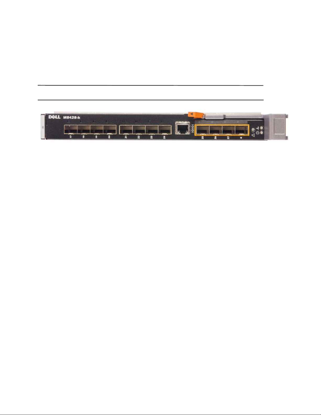
FIGURE 1
Port Side of M8428-k
Unpacking and installing the converged network switch
If the converged network switch is installed in the blade server enclosure that is shipped to you, skip this section.
This section applies when installing a new module in an empty I/O module slot or when replacing an existing
converged network switch.
Perform the following steps to remove the switch module from its shipping package.
1. Open the shipping box and inspect the contents, making sure that nothing is missing or damaged.
Do not insert a damaged converged network switch into the blade server enclosure. If the switch module
appears to be damaged, contact your sales representative before proceeding.
2. Remove the Getting Started Guide containing regulatory statements from on top of the switch module.
3. Remove the switch module from the box.
4. Be sure that you have taken the necessary precautions for electrostatic sensitivity; then break the warning seal.
5. Slide the switch module out of the antistatic sleeve and inspect it carefully for any obvious defects or shipping
damage.
6. Remove the orange colored protective connector cover from the back of the switch module (pull).
7. Install the I/O module in the M1000e enclosure.
a. Lift the handle release latch and open the I/O module handle.
b. Slide the module into the appropriate I/O slot of the M1000e enclosure.
c. Close the handle until it snaps securely into place and the module is fully seated.
Dell M8428-k Getting Started Guide 3 of 192
MHWKY A01
Page 4
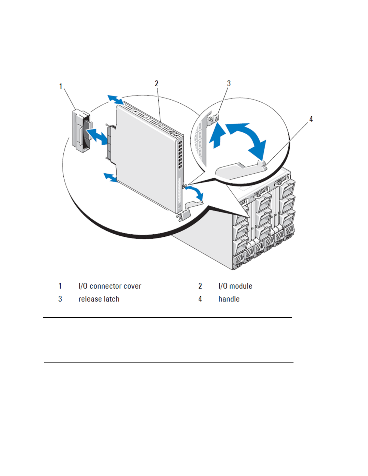
FIGURE 2
NOTE
Installing an I/O module into a Dell PowerEdge M1000e enclosure
The switch module should be installed into the I/O slot that corresponds to the I/O fabric (A, B, or C) that the
10GE Converged Network Adapter (CNA), within the blade server, is appropriately installed. The Chassis
Management Controller (CMC) GUI can be used to view the location of network adapters installed in the Blade
servers. Browse to the CMC IP address and login, then under "Server Overview" click on the servers (under
Server Overview) to determine which I/O slots contain the 10GE CNA's.
8. For complete instructions for installing a switch module into the blade server enclosure, refer to the section on
installing an I/O module in the Dell PowerEdge Modular Systems Hardware Owner’s Manual.
4 of 192 Dell M8428-k Getting Started Guide
MHWKY A01
Page 5

Configuring the converged network switch
NOTE
NOTE
Use procedures in this section to configure the converged network switch to operate on a network and fabric.
Provided are steps to assign an IP address for the Ethnert Management Network, and how to change the module’s
Fiber Channel operating mode.
Although the converged network switch is configured at the factory for NPIV mode, NPIV mode can be disabled to use
full fabric mode as needed. Refer to procedures under the section titled “Changing from NPIV aggregator mode to full
fabric mode” on page 13.
This publication provides procedures that use the Chassis Management Controller (CMC) browser-based GUI
application and the switch Command Line Interface (CLI) to configure the switch module. Other methods exist for
managing I/O modules and can also be used.
Items required
The following items are required for configuring and connecting the converged network switch for use in a network
and fabric:
•
The converged network switch installed in a blade server enclosure.
•
A management workstation (computer) that has a terminal emulator (such as HyperTerminal) connected to the
Chassis Management Controller (CMC) GUI or CLI via Ethernet or Seial port, or connected to the CMC or
converged network switch CLI through the keyboard, video, and mouse (KVM) device of the blade server
enclosure.
•
An unused IP address and corresponding subnet mask and gateway address unless DHCP is used.
•
If required, a serial cable to connect to the switch module serial console port. Note that this is not required if
changing the converged network switch IP address through the Chassis Management Controller (CMC) or KVM
of the blade server enclosure using the CMC GUI or CLI.
•
SFP transceivers and compatible fibre cables, as required. The switch module can also use active twin-ax
copper cables on the 10G Enhanced Ethernet ports.
Use only Dell-approved SFPs or active twin-ax copper cables on the external ports of this module.
TABLE 1
330-7596 (FI) 7YMX4 PCT B-8000 10GbE TWINAX 3 METER 8PACK
330-7611 (APOS) Y938W
330-7595 (FI) M7W74 PCT B-8000 10GbE TWINAX 5 METER 1PACK
330-7609 (APOS) 1GH9D
330-7597 (FI) P4G6K PCT B-8000 10GbE TWINAX 5 METER 8PACK
330-7614 (APOS) 8Y9H3
330-7593 (FI) 13HFP PCT B-8000 10GbE TWINAX 1 METER 1PACK
330-7610 (APOS) FDPWD
330-7594 (FI) KRDN3 PCT B-8000 10GbE TWINAX 1 METER 8PACK
330-7615 (APOS) YFCMW
Dell M8428-k Getting Started Guide 5 of 192
MHWKY A01
10GbE Optical Transceivers & TWINAZ Connectors+Cables
Page 6
NOTE
TABLE 1
330-7598 (FI) Y4NV0 PCT B-8000 10GbE TWINAX 3 METER 1PACK
330-7612 (APOS) T40FD
430-3684 (FI) TNCYY PCT B-8000 10GbE, SFP+, LW, 10KM
330-7603 (APOS) G3C42
430-3685 (FI) DW85K PCT B-8000 10GbE SFP+, LW, 10KM, 8PACK
330-7606 (APOS) MYNX0
430-3686 (FI) SHPYV PCT B-8000 10GbE, SFP+, SW, 2KM
330-7605 (APOS) TGNV7
430-3687 (FI) K0FP0 PCT B-8000 10GbE, SFP+, SW, 8PACK
330-7608 (APOS) 3RX9C
10GbE Optical Transceivers & TWINAZ Connectors+Cables
TABLE 2
330-7602 (APOS) 54HC1 PCT B-8000 8GB 10KM LW SFP
330-7604 (APOS) 3D1YG PCT B-8000 8GB SFP+, SW, 2KM
330-7607 (APOS) 2F2KF PCT B-8000 8GB SFP+, SW, 2KM, 8PACK
•
Access to an FTP server on the Ethernet management network, for backing up the converged network switch
configuration.
•
Access to these publications:
•
•
•
•
•
•
•
•
•
•
FC 8Gbps SFP+ Optical Transceivers (spares/replacements for factory installed SWL Optics)
Dell PowerEdge Modular Systems Hardware Blade Server Enclosure Hardware Owner's Manual
Dell PowerEdge M1000e Blade Server Enclosure Configuration Guide
53-1001980 Dell M8428-k Hardware Reference Manual
53-1002116 Dell Converged Enhanced Ethernet Administrators Guide
53-1002115 Dell Converged Enhanced Ethernet Command Reference
53-1001345 Access Gateway Administrators Guide
53-1001343 Web Tools Administrators Guide
53-1001336 Fabric OS Administrators Guide
53-1001754 Fabric OS Command Reference Manual
Dell Chassis Management Controller (CMC) Users Guide
These guides can be found at support.dell.com/support under PowerEdge M1000E, manuals and documentation.
6 of 192 Dell M8428-k Getting Started Guide
MHWKY A01
Page 7
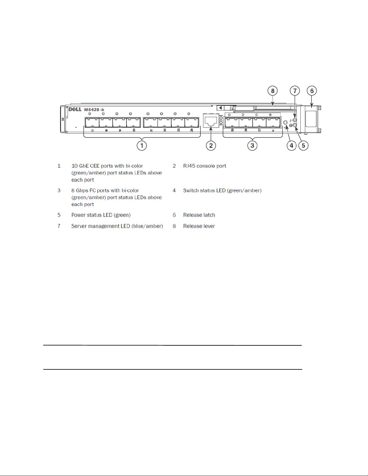
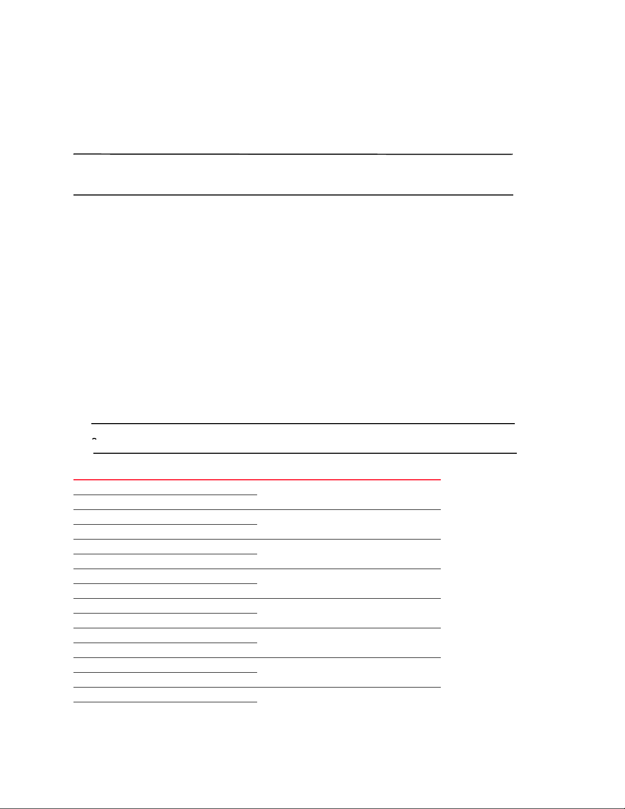
FIGURE 3
NOTE
Description of the M8428-k external ports, status LED’s and release latch.
Modify the converged network switch Ethernet management IP address
By default, the Ethernet management IP address for the converged network switch is configured as 10.77.77.77 with
a default Ethernet subnet mask of 255.255.255.0. The default gateway is 0.0.0.0.
Reset the IP address using one of the available methods, which store the IP address values on the switch module:
•
Blade server enclosure CMC graphical user interface (GUI).
•
Blade server enclosure CMC CLI.
•
Dell M8428-k command line interface (CLI).
After modifying the switch module’s IP address and domain name (if the switch module is in full fabric mode), we
recommend that you cable all external ports to fabric connections before bringing the switch module online.
It is recommended that you set the IP address using the blade server enclosure CMC GUI application because this
enables centralized management of the converged network switch.
Using the CMC GUI to set the IP address
Browse to the Chassis Management Controller (CMSC) IP address and login.
To change the IP address, use the following steps:
Dell M8428-k Getting Started Guide 7 of 192
MHWKY A01
Page 8
1. Click the I/O Module Overview in the navigation panel of the CMC menu.
ATTENTION
NOTE
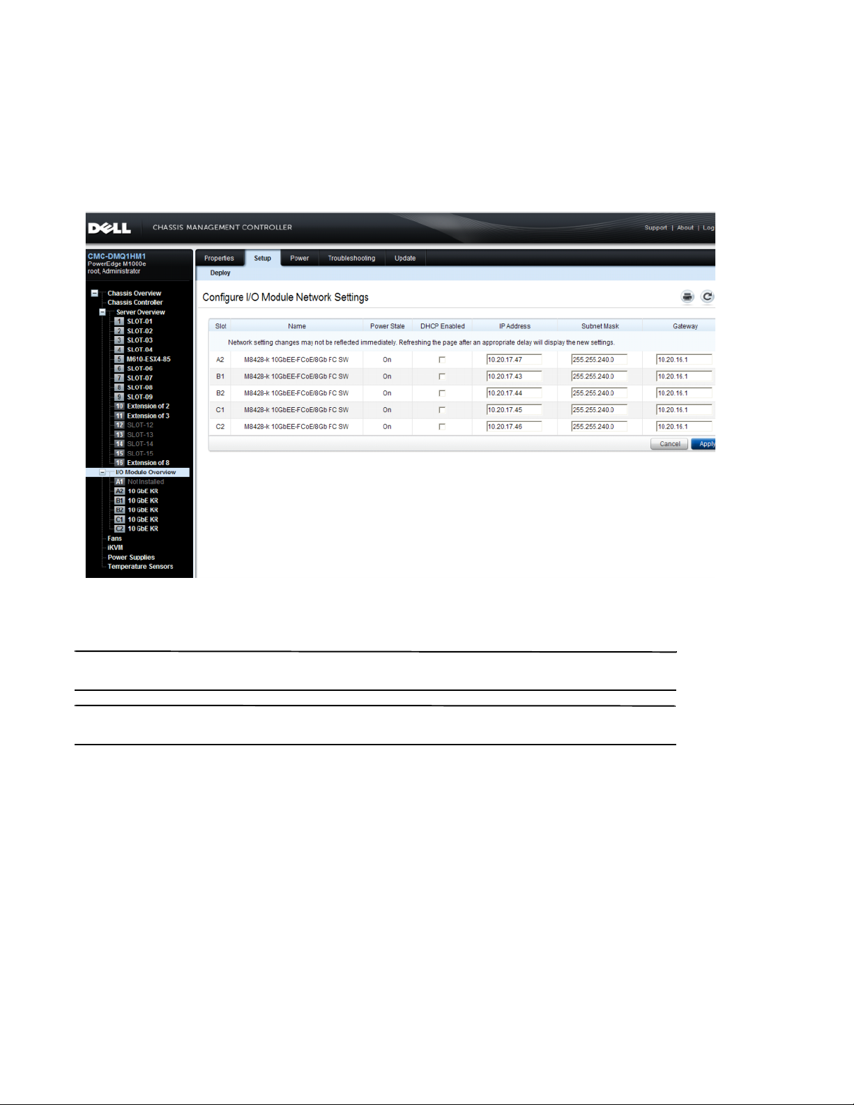
2. Open the CMC application’s Setup tab.
FIGURE 4
CMC Setup Tab
3. Enter the new information in the IP Address for the correct I/O slot, Subnet Mask, and Gateway fields, or enable
DHCP, as appropriate and click Apply.
In order to see the applied settings click the “Refresh” icon.
TRefer to the documentation for the Dell Chassis Management Controller (CMC) for additional GUI detail.
Using the CMC CLI to set the IP address
Use the following steps to connect and modify the converged network switch IP address through the CMC CLI.
1. Establish a Telnet session to the CMC CLI.
•
At the CMC login prompt, enter the CMC username and password.
2. At the command prompt, type the setniccfg command with the correct IP information as shown in the following
example:
•
$ racadm setniccfg -m switch-x -s 10.32.53.47 255.255.240.0 10.32.48.1
Static IP address modified succesfully
3. Substitute the correct value for switch-x where x is the bay where the switch module is installed. For example,
switch-x can be:
8 of 192 Dell M8428-k Getting Started Guide
MHWKY A01
Page 9

•
NOTE
NOTE
switch-1 for switch module installed in bay A1.
•
switch-2 for switch module installed in bay A2.
•
switch-3 for switch module installed in bay B1.
•
switch-4 for switch module installed in bay B2.
•
switch-5 for switch module installed in bay C1.
•
switch-6 for switch module installed in bay C2.
4. Enter racadm getniccfg -m switch-x at the prompt to verify that the address was correctly set.
Refer to the documentation for the Dell Chassis Management Controller (CMC) for additional racadm command
details.
Using the Dell M8428-k CLI to set the IP address
To set the IP address of the switch module using the switch CLI via Serial port (rather than through the CMC), refer to
the Dell M8428-k Hardware Reference Manual under the section with this same section name.
Connecting to the converged network switch management interface
After succesfully setting the IP address of the switch module, a terminal emulator (Telnet, SSH) CLI connection can
be established to the converged switch module, from a remote management workstation, through the Chassis
Management Controller (CMC) Ethernet port. The management interface can be used for any additional
configuration of the switch module.
The default switch module login/password the Admin account is: admin/password
Dell M8428-k Getting Started Guide 9 of 192
MHWKY A01
Page 10
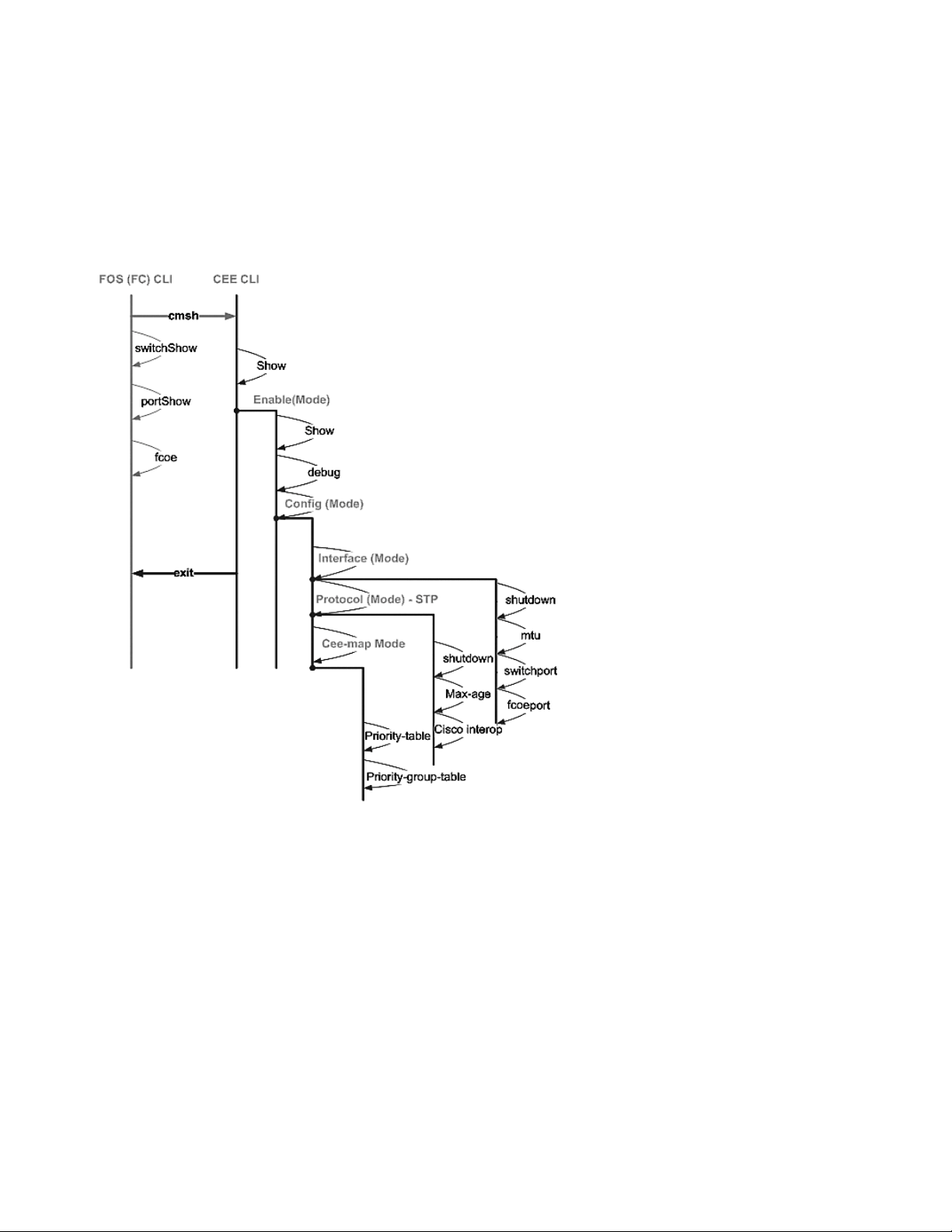
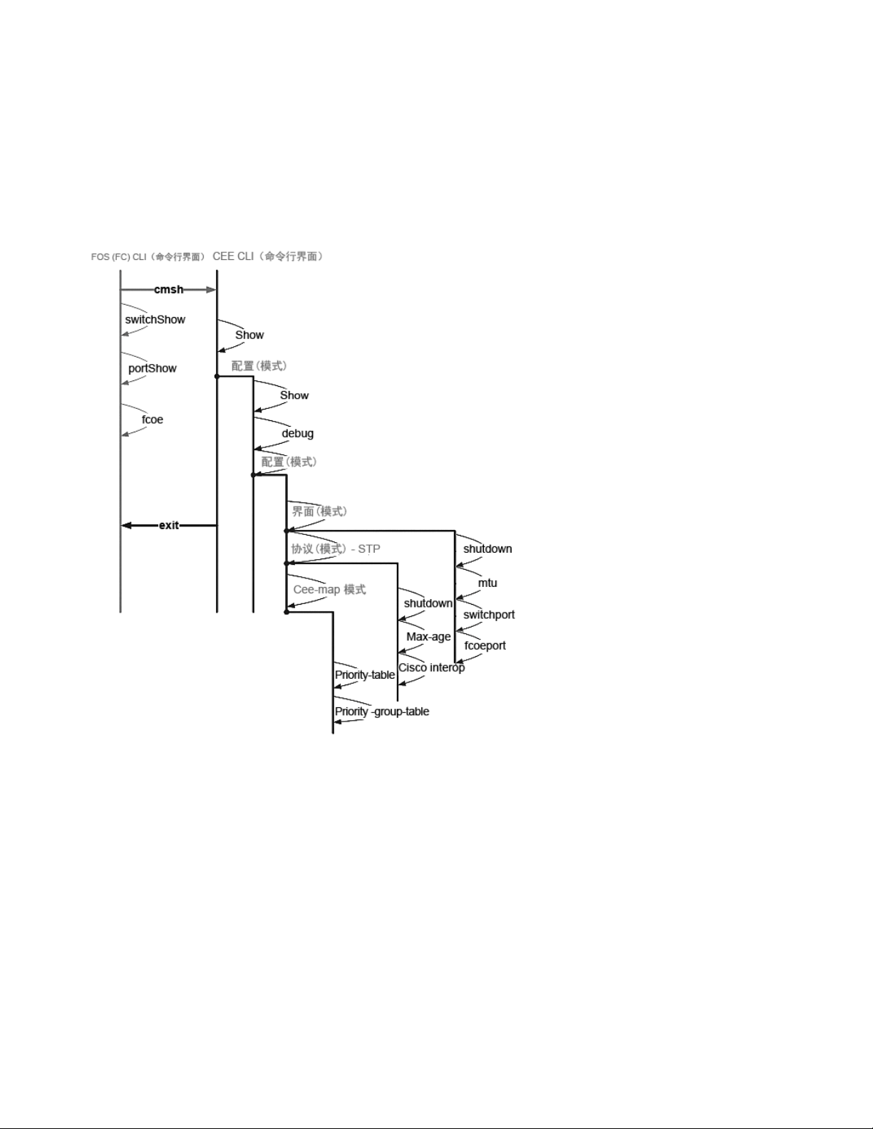
The diagram below shows the separation spaces for common FOS commands and CEE commands which are
navigated using the CLI mode commands (cmsh, enable, configure, and interface). Within the CEE CLI use "?" for
help with commands and tab for auto complete. Within the FOS CLI use help for command syntax.
FIGURE 5
Converged switch module CLI mode hierarchy for FOS and CEE commands
Additionally, a browser based GUI connection to the switch module is available (WebTools - requires JRE) which can
be used for the common commands needed to configure the switch module. See the Fabric OS Administrators
Guide for details on GUI interface use.
Configuring internal ports for FCoE
The internal midplane ports of the converged switch module need to be configured for use with the Converged
Network Adapter (CNA), in the blade servers, in order for FCoE connectivity to occur.
Once you have logged into the switch, use the cmsh command to access the CEE command shell. Use the following
steps to configure the CEE ports.
1. Login to the switch. with the Admin account. Default Admin password = password.
2. Enter the following command:
10 of 192 Dell M8428-k Getting Started Guide
MHWKY A01
Page 11

M8428-k:Admin> cmsh
NOTE
NOTE
NOTE
M8428-k#
3. Once in the command shell, enter the following command:
enable
4. Then Enter the following command to enter configure mode:
configure terminal
5. Enter the following commands:
interface intengigabitethernet 0/x
a.
, where x is the internal port you wish to change, which is the Slot
position of the server blade with the Converged Network Adapter being connected to.
The internal ports are numbered 1 through 16 corresponding to the server blade slot positions. The external
ports would be configured with the command interface exttengigabitethernet 0/x, but the external ports would
only be set to FCoE mode when connected to an external Host Server with a CNA. The external ports should not
be connected to another FCoE Switch.
6. Once in the interface for the port, enter the following commands in the order shown:
fcoeport
exit
The interface command fcoeport applies the following to the interface to enable FCoE traffic:
The corresponding FCoE VLAN is applied to the interface (VLAN 1002)
The corresponding CEE map is applied to the interface (“default”)
The FCoE/FIP VLAN classifiers are applied to the interface
See the Dell Converged Enhanced Ethernet administrators guide for more details of this command.
7. Repeat steps 5-6 for any other ports for additional server blade slots you wish to configure. Additionally as
needed, configure the internal ports for converged mode with a VLAN for untagged frames for non FC traffic, and
configure FC trunks or LACP LAG’s on external ports.
To view the CEE port configuration type: do show running-config
To view FCoE device connectivity type: do fos switchshow and do fos fcoe --loginshow
8. Once finished with all of the blade ports, type exit and press Enter (you should still be in the CMSH at this point).
9. Enter the following command to save the running config as the startup config:
write memory
Answer yes to overwrite the startup file.
See the Converged Enhanced Ethernet Administrator’s Guide for information about CEE CLI interface and
configuring switches for FCoE operation and the Converged Enhanced Ethernet Command Reference for more
details on the commands.
Dell M8428-k Getting Started Guide 11 of 192
MHWKY A01
Page 12

Connecting the converged network switch to the fabric
NOTE
ATTENTION
NOTE
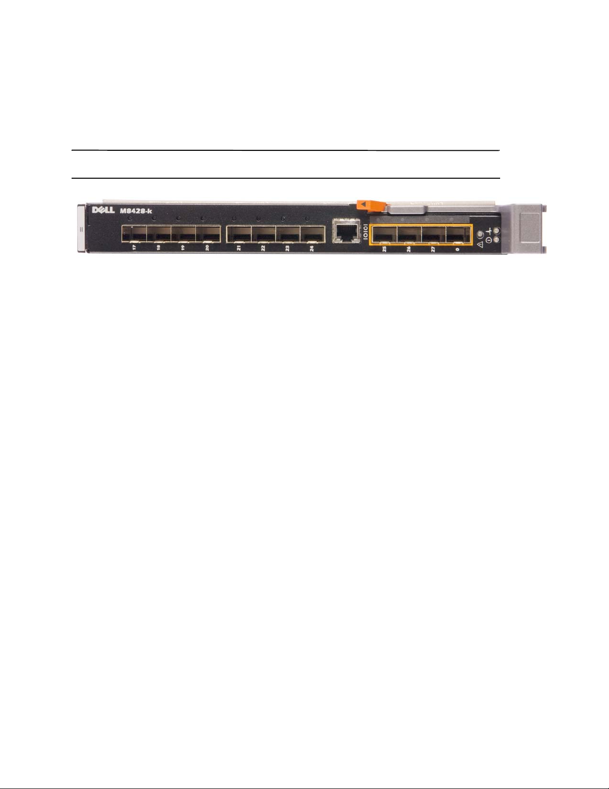
1. The switch module is delivered with FC 8G SFP transceivers installed in the four fibre channel ports.
2. If you need to connect the Ethernet ports, install 10GE SFP+ transceivers or twin-ax cables in the external ports
as required. Be sure you have all the necessary SFP transceivers as well as either optical or active twin-ax
copper cables.
a. If necessary, remove the end caps from the SFP.
b. Orient the transceiver correctly and insert it into a port until it is firmly seated and the latching mechanism
clicks.
For instructions specific to the type of transceiver, refer to the transceiver manufacturer’s documentation.
c. Repeat substeps a, b, and c for the remaining ports, as required.
Use only Dell-approved SFPs or active twin-ax copper cables in the appropriate external optical ports of this
module. The FC 8G SFP transceivers included in the 4 Fibre Channel ports (25, 26, 27, and 0) of the switch
module are not compatible with the Ethernet ports (17 through 24). The Ethernet ports should be populated
with Dell-Approved 10GE SFP+ transceivers, or active twin-ax copper cables (not included).
A cable should not be bent to a radius less than 5.08 cm (2 inches) under full tensile load and 3.048 cm (1.2
inches) with no tensile load. Tie wraps are not recommended for optical cables because they are easily over
tightened.
d. Orient a cable connector so that the key (the ridge on one side of connector) aligns with the slot in the
transceiver
e. Insert the cable into the transceiver until the latching mechanism clicks. For instructions specific to cable
type, refer to the cable manufacturer's documentation.
f. Repeat for the remaining transceivers as required.
3. Connect the cables to the transceivers.
The transceivers are keyed to ensure correct orientation. If a transceiver does not install easily, ensure that it is
correctly oriented and that the end caps have been removed.
4. Check the LEDs to verify that all components are functional.
For information about LED patterns, see the “Operating the converged network switch” chapter in the Dell
M8428-k Hardware Reference Manual.
Commands below are run from the FOS CLI, as needed exit the CEE CLI, or login to the Switch with a terminal
emulator session and gain access the FOS prompt
5. Once the switch module FC port is connected to an FC SAN switch, the ports need to be enabled. From the
switch module FOS CLI enter the following command for the ports being used (this can also be enabled from the
switch GUI):
M8428-k:admin> portcfgpersistentenable <port#>, where the port# is 25, 26, 27 or 0.
M8428-k:Admin>
6. Verify the correct operation of the converged network switch by typing the switchShow command from the
workstation. This command provides information about the switch module and port status.
12 of 192 Dell M8428-k Getting Started Guide
MHWKY A01
Page 13

7. Verify the correct operation of the converged network switch in the fabric by typing the fabricShow command
NOTE
from the workstation.
8. Back up the switch module configuration to an FTP server by typing the configUpload command and following
the prompts.
These commands upload the converged network switch configuration to the server, making it available for
downloading to a replacement converged network switch if necessary. Additionally the CEE configuration should
be backed up on a regular basis to ensure that a complete configuration is available for downloading to a
replacement switch module. See “Backing up the configuration” on page 15 for complete details.
Fibre Channel SwitchMode (NPIV aggregator vs. full fabric)
The following points summarize the differences between a Fabric OS switch functioning in Native Operating mode
(full fabric mode) and a Fabric OS switch functioning in AG operating mode (NPIV aggregator):
•
The Fabric OS switch in Native mode is a part of the fabric; it requires two to four times as many physical
ports, consumes fabric resources, and can connect to a Fabric OS fabric only.
•
A switch in AG mode is outside of the fabric; it reduces the number of switches in the fabric and the number
of required physical ports. You can connect an AG switch to either a Fabric OS, M-EOS, or Cisco-based fabric.
Determine whether the Fibre Channel portion of the switch module is in NPIV or full fabric mode. This setting affects
the configuration process for the FOS portion of the switch module.
In NPIV aggregator mode, only a limited subset of the fabric operating system commands are available and all
fabric-related service requests are forwarded to the fabric switches.
When the switch mode is set to Access Gateway mode enabled, the F_Ports connect to the Enterprise fabric as
N_Ports rather than as E_Ports. Therefore at least one of the external FC ports must be connected to an external
FC switch fabric in order for the internal ports connected to Converged Network Adapter’s (CNA’s) to be able to
login to the FCoE ports on the switch
Using the converged network switch CLI, verify the desired switch operating mode (The switch module is shipped
with Access Gateway Mode enabled):
Log onto the switch module through an SSH or Telnet connection, using the admin account (default password:
password).
You can enter the ag ––modeShow command to ensure that the module is in NPIV mode.
ag --modeShow
The factory default response will say:
Access Gateway mode is enabled.
module.
Changing from NPIV aggregator mode to full fabric mode
If your converged network switch is currently configured in NPIV mode (the factory default setting), you can enable
the module for full fabric mode by disabling Access Gateway mode. When you do this, the module automatically
reboots in full fabric mode.
Disabling NPIV mode is disruptive because the switch is disabled and rebooted. Always back up the current
configuration before enabling or disabling NPIV mode. Enabling NPIV mode clears the security and zone databases.
Disabling NPIV mode clears the F_Port to N_Port mapping.
Dell M8428-k Getting Started Guide 13 of 192
MHWKY A01
Page 14

Changing to full fabric mode using the Command Line Interface
Complete the following steps to enable NPIV mode using the CLI (The switch GUI also provides a method to change
NPIV mode in the advanced menu, see the Dell M8428-k hardware Reference Manual for details).
1. Log in using the default administrative account.
Login: admin
Password: password
2. Enter the following command to disable the switch.
switchDisable
3. Back up the switch configurations. See “Backing up the configuration” on page 15 for specifics.
4. Enter the following command to enable full fabric mode:
ag ––modeDisable
The switch module automatically reboots and comes back online in full fabric mode. The NPIV parameters, such
as port mapping and failover and failback, are automatically removed.
You can enter the ag ––modeShow command to ensure that the module is in NPIV mode.
ag ––modeShow
The response should be:
Access Gateway mode is NOT enabled.
Changing to NPIV mode using the Command Line Interface
If your converged network switch is currently configured in full fabric mode you canenable NPIV mode using the
following instructions (The switch GUI also provides a method to change NPIV mode in the advanced menu, see the
Dell M8428-k Hardware Reference Manual for details):
1. Log in using the default administrative account.
Login: admin
Password: password
2. Enter the following command to disable full fabric mode.
switchDisable
3. Back up the switch configurations. See “Backing up the configuration” on page 15 for specifics.
4. Enter the following command to enable NPIV mode:
ag ––modeEnable
The switch module automatically reboots and comes back online in NPIV mode using a factory default F_Port to
N_Port mapping.
5. You can enter the ag ––modeShow command to ensure that the module is in NPIV mode.
ag --modeShow
The response should be:
Access Gateway mode is enabled.
14 of 192 Dell M8428-k Getting Started Guide
MHWKY A01
Page 15

You can also enter the ag ––mapshow command to display the F_Port to N_Port mapping. Enter ag ––help
command to display a list of all NPIV actions.
Verify FCOE connectivity in NPIV aggregator mode
When the switch mode is set to Access Gateway mode enabled, the F_Ports connect to the Enterprise fabric as
N_Ports rather than as E_Ports. Therefore at least one of the external FC ports must be connected to an external FC
switch fabric in order for the internal ports connected to Converged Network Adapter's (CNA's) to be able to login to
the FCoE ports on the switch module.
The connectivity of the switch module with the CNA's can be verified using the FOS commands switchshow and fcoe
--loginshow. The internal ports should show "online" State, with connectivity of internal FCoE VF-ports to the CNA
VN-ports shown by the session MAC address. See "AccessGateway_AG_v630" admin guide for details on the NPIV
aggregator mode.
Once the switch module FC port is connected to an FC SAN switch, the ports may need to be enabled. From the
switch module FOS CLI enter the following command for the ports being used (this can also be enabled from the
switch GUI):
M8428-k:admin> portcfgpersistentenable <port#>, where the port# is 25, 26, 27 or 0.
Backing up the configuration
Perform these steps to back up the switch module configuration to an FTP server.
1. Open a Telnet or SSH session to the switch module.
2. Enter the following command to upload the basic configuration of the switch module:
configUpload
You are then presented with a series of prompts.
3. Follow the prompts to upload the configuration.
4. When the upload completes, enter the following command to access the CEE CLI:
cmsh
5. Enter the following command to upload the current CEE configuration:
copy running-config ftp://[username@server/path]
You are then prompted for a password. When you enter the ftp password, the copy procedure begins.
These commands upload the switch module configurations to the server, making it available for downloading to a
replacement switch module if necessary. Dell recommends backing up the configuration on a regular basis to
ensure that a complete configuration is available for downloading to a replacement switch module.
Dell M8428-k Getting Started Guide 15 of 192
MHWKY A01
Page 16

16 of 192 Dell M8428-k Getting Started Guide
MHWKY A01
Page 17

MHWKY A01
2010 年 10 月 15 日
Dell M8428-k
使用入门指南
53-1002029-01 Rev. B
*53-1002029-01*
Page 18

本说明文件中的信息如有更改,恕不另行通知。
©2010DellInc. 版权所有,翻印必究。
未经 Dell Inc. 书面许可,严禁以任何形式复制这些材料。
本文中使用的商标:Dell、 DELL 徽标、 Inspiron、 Dell Precision、 Dimension、 OptiPlex、 Latitude、 PowerEdge、 PowerVault、 PowerApp、
PowerConnect、和 Dell OpenManage 是 Dell Inc. 的商标; Intel、 Pentium、和 Celeron 是 Intel Corporation 在美国和其他国家或地区的注册商
标; Microsoft、Windows、Windows Server、MS-DOS 和 Windows Vista 是 Microsoft Corporation 在美国和 / 或其他国家或地区的商标或注册
商标。
本说明文件中述及的其它商标和产品名称是指拥有相应商标和产品名称的公司或其制造的产品。
Dell Inc. 对不属于自己的商标和商品名称不拥有任何所有权。
管制型号代码:M8428-k
18/192 Dell M8428-k 使用入门指南
MHWKY A01
Page 19
概览
注
本 《使用入门指南》旨在作为一份概览,帮助有经验的安装者快速地拆封、安装和配置 Dell M8428-k。有关详
细的安装和配置说明,请参阅 《Dell M8424-k 硬件参考手册》。
在本说明文件中,将 Dell M8428-k 称为 汇聚网络交换机 或 交换机模块。
图 1
M8428-k 的端口侧
拆封并安装 汇聚网络交换机
如果汇聚网络交换机已安装在运送给您的刀片服务器机柜上,请跳过本节。本节适用于在空 I/O 模块插槽中安
装新模块或更换现有的汇聚网络交换机。
执行以下步骤,将交换机模块从其运输包装中取出。
1. 打开包装箱,检查其是否有配件损坏或丢失。
切勿将损坏的汇聚网络交换机插入刀片服务器机柜。如怀疑 交换机模块已损坏,请在进行下一步操作前,
联系您的销售代表。
2. 从交换机模块的上方取出包含管制声明的 《使用入门指南》。
3. 将 交换机模块从包装箱中取出。
4. 确保您针对静电感应采取了必要的预防措施;然后打开警告密封条。
5. 将 交换机模块从防静电护套中滑出并仔细检查是否有明显的缺陷或运输损伤。
6. 从交换机模块的背面卸下橙色接头保护罩 (拉)。
7. 在 M1000e 机壳中安装 I/O 模块。
a. 提起手柄释放闩锁并打开 I/O 模块手柄。
b. 将模块滑入 M1000e 机柜相应的 I/O 插槽。
c. 关闭手柄,直至其稳固地卡入到位并且模块完全就位。
Dell M8428-k 使用入门指南 19/192
MHWKY A01
Page 20
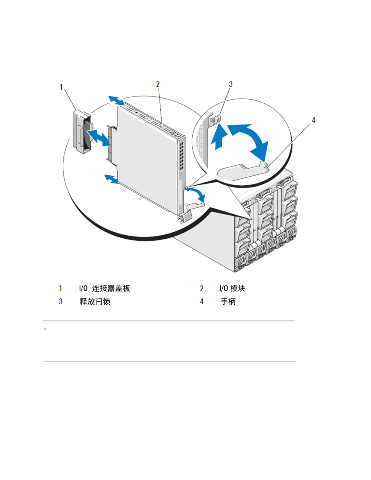
图 2
注
将 I/O 模块安装到 Dell PowerEdge M1000e 机柜中
交换机模块应该安装到对应于 I/O 组构(A、 B 或 C),且已相应地安装到刀片服务器内的 10GE 汇聚网络适
配器 (CNA) 的 I/O 插槽。机箱管理控制器 (CMC) GUI 可用于查看刀片服务器内安装的网络适配器的位置。浏
览到 CMC IP 地址并登录,然后在 “ 服务器概览 ” 下,单击服务器 (在 “ 服务器概览 ” 下),以确定包
含 10GE CNA 的 I/O 插槽。
8. 有关将交换机模块安装到刀片服务器机柜的完整说明,请参阅 《Dell PowerEdge Modular Systems 硬件用户
手册》中有关安装 I/O 模块的章节。
20/192 Dell M8428-k 使用入门指南
MHWKY A01
Page 21
配置 汇聚网络交换机
注
注
按照本节中的步骤配置 汇聚网络交换机 ,使其运行于网络和组构上。提供的是为以太网管理网络指派 IP 地
址,以及如何更改模块光纤信道操作模式的步骤。
尽管汇聚网络交换机在出厂时已配置为 NPIV 模式,但可以根据需要禁用 NPIV 模式以使用完全组构模式。请参
阅第 31 页上的 “ 备份配置 ” 一节中的步骤。
本出版物提供使用 基于浏览器的机箱管理控制器 (CMC) GUI 应用程序和交换机命令行界面 (CLI) 配置交换机模
块的步骤。也可以使用其他已有的用于管理 I/O 模块的方法。
设备要求
要配置和连接 汇聚网络交换机用于网络和组构中,需满足以下要求:
•
汇聚网络交换机已安装在刀片服务器机柜中。
•
一个管理工作站 (计算机),其终端仿真器(如 HyperTerminal)已通过以太网或串行端口连接到机箱管理
控制器 (CMC) GUI 或 CLI,或已通过刀片服务器机柜的键盘、视频和鼠标 (KVM) 设备连接到 CMC 或汇聚网络
交换机 CLI。
•
未使用的 IP 地址及相应的子网掩码和网关地址,除非使用了 DHCP。
•
用于连接 交换机模块 串行控制台端口的串行电缆,视需求而定。请注意,如果通过机箱管理控制器 (CMC)
或刀片服务器机柜的 KVM,并使用 CMC GUI 或 CLI 来 更改汇聚网络交换机 IP 地址,则不需要此电缆。
•
SFP 收发机及与之兼容的光缆,视需求而定。交换机模块 还可在 10G 增强型以太网端口上使用有源双轴铜
缆。
请仅在此模块的外部端口上使用 Dell 认可的 SFP 或有源双轴铜缆。
表 1
330-7596 (FI) 7YMX4
330-7611 (APOS) Y938W
330-7595 (FI) M7W74
330-7609 (APOS) 1GH9D
330-7597 (FI) P4G6K
330-7614 (APOS) 8Y9H3
330-7593 (FI) 13HFP
330-7610 (APOS) FDPWD
330-7594 (FI) KRDN3
330-7615 (APOS) YFCMW
330-7598 (FI) Y4NV0
330-7612 (APOS) T40FD
430-3684 (FI) TNCYY
330-7603 (APOS) G3C42
430-3685 (FI) DW85K
330-7606 (APOS) MYNX0
10GbE 光纤收发机和 TWINAZ 接头 + 光缆
PCT B-8000 10GbE TWINAX 3 米 8 包
PCT B-8000 10GbE TWINAX 5 米 1 包
PCT B-8000 10GbE TWINAX 5 米 8 包
PCT B-8000 10GbE TWINAX 1 米 1 包
PCT B-8000 10GbE TWINAX 1 米 8 包
PCT B-8000 10GbE TWINAX 3 米 1 包
PCT B-8000 10GbE, SFP+, LW, 10
PCT B-8000 10GbE SFP+, LW, 10 千米 , 8 包
装
装
装
装
装
装
千米
装
Dell M8428-k 使用入门指南 21/192
MHWKY A01
Page 22

注
表 1
430-3686 (FI) SHPYV
330-7605 (APOS) TGNV7
430-3687 (FI) K0FP0
330-7608 (APOS) 3RX9C
10GbE 光纤收发机和 TWINAZ 接头 + 光缆
PCT B-8000 10GbE, SFP+, SW, 2 千米
PCT B-8000 10GbE, SFP+, SW, 8 包
装
表 2
330-7602 (APOS) 54HC1
330-7604 (APOS) 3D1YG
330-7607 (APOS) 2F2KF
•
访问以太网管理网络中的 FTP 服务器,以备份汇聚网络交换机配置。
•
有权使用以下出版物:
•
•
•
•
•
•
•
•
•
•
FC 8Gbps SFP+ 光纤收发机 (适用于出厂安装的 SWL 光学器件的备件 / 更换件)
千米
PCT B-8000 8GB 10
PCT B-8000 8GB SFP+, SW, 2 千米
PCT B-8000 8GB SFP+, SW, 2 千米, 8 包
LW SFP
装
Dell PowerEdge 模块化系统硬件刀片服务器机柜硬件用户手册
Dell PowerEdge M1000e 刀片服务器机柜配置指南
53-1001980 Dell M8428-k 硬件参考手册
53-1002116 Dell 汇聚增强型以太网管理员指南
53-1002115 Dell 汇聚增强型以太网命令参考
53-1001345 Access Gateway 管理员指南
53-1001343 Web 工具管理员指南
53-1001336 Fabric OS 管理员指南
53-1001754 Fabric OS 命令参考手册
Dell 机箱管理控制器 (CMC) 用户指南
这些指南在 support.dell.com/support 上的 PowerEdge M1000E、手册和说明文件中提供。
22/192 Dell M8428-k 使用入门指南
MHWKY A01
Page 23
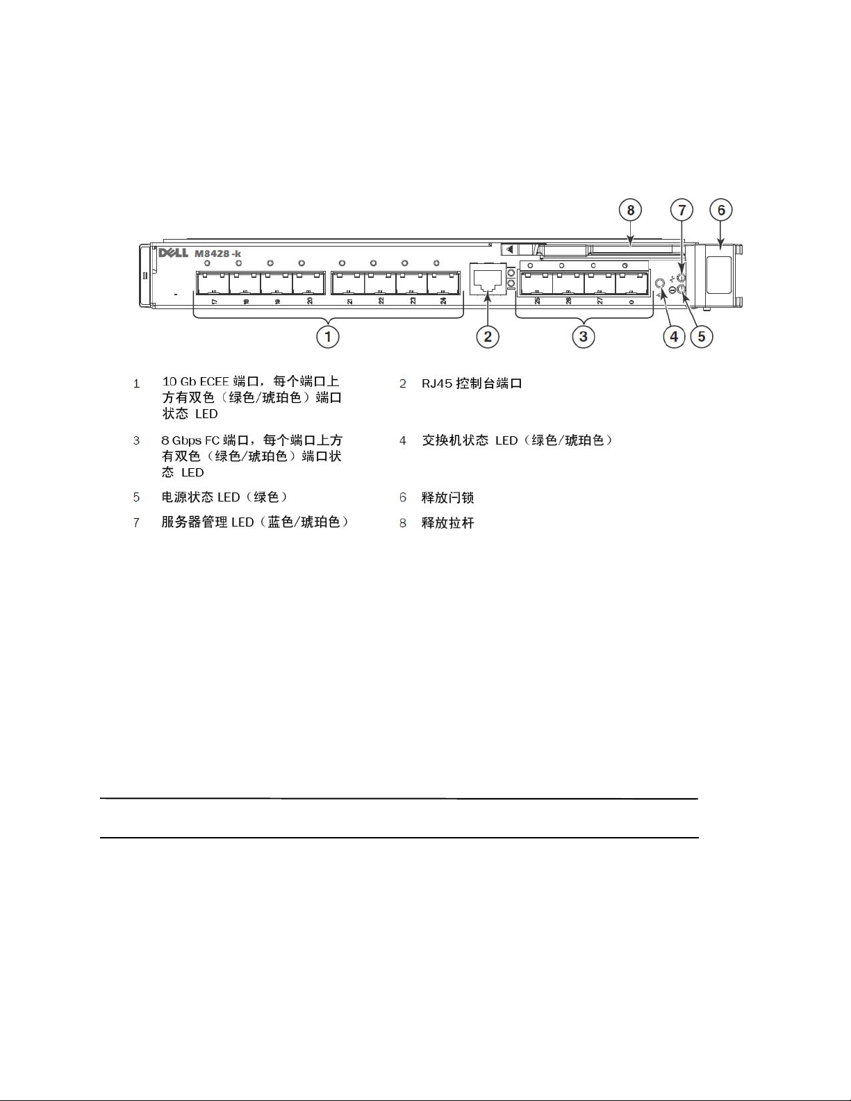
图 3
注
M8428-k 外部端口、状态 LED 指示灯及释放闩锁的描述
修改汇聚网络交换机以太网管理 IP 地址
默认情况下,汇聚网络交换机的以太网管理 IP 地址配置为 10.77.77.77,默认以太网子网掩码为
255.255.255.0。默认网关为 0.0.0.0。
使用一种可用的方法重置 IP 地址,这会将 IP 地址值存储在交换机模块上:
•
刀片服务器机柜 CMC 图形用户界面 (GUI)。
•
刀片服务器机柜 CMC CLI。
•
Dell M8428-k 命令行界面 (CLI)。
修改 交换机模块 的 IP 地址和域名 (如果 交换机模块 处于完全组构模式)之后,我们建议您在将 交换机模块
联机之前,对所有外部端口布线至组构连接。
推荐使用刀片服务器机柜 CMC GUI 应用程序来设置 IP 地址,因为这可以对 汇聚网络交换机启用集中化管理。
Dell M8428-k 使用入门指南 23/192
MHWKY A01
Page 24
利用 CMC GUI 设置 IP 地址
注意
注
浏览到机箱管理控制器 (CMSC) IP 地址并登录。
要更改 IP 地址,使用以下步骤:
1. 单击 CMC 菜单导航面板中的 I/O Module Overview (I/O 模块概览)。
2. 打开 CMC 应用程序的 Setup (设置)选择卡。
图 4
CMC 设置选项卡
3. 在正确 I/O 插槽的 IP Address (IP 地址)、 Subnet Mask (子网掩码)和 Gateway (网关)适用字段中输入
新信息,然后单击 Apply (应用)。
要查看应用的设置,请单击 “Refresh”(刷新)图标。
请参阅 Dell 机箱管理控制器 (CMC) 说明文件以了解更多的 GUI 详细信息。
24/192 Dell M8428-k 使用入门指南
MHWKY A01
Page 25

利用 CMC CLI 设置 IP 地址
注
注
利用以下步骤,通过 CMC CLI 来连接和修改汇聚网络交换机 IP 地址。
1. 建立到 CMC CLI 远程登录会话。
•
在 CMC 登录提示符下,输入 CMC 用户名和密码。
2. 在命令提示符下,键入具有正确 IP 信息的 setniccfg 命令,如以下示例中所示:
•
$ racadm setniccfg -m switch-x -s 10.32.53.47 255.255.240.0 10.32.48.1
静态 IP 地址已成功修改。
3. 将 switch-x 替换成正确值,其中 x 是安装交换机模块的托架。例如, switch-x 可以是:
•
switch-1,代表交换机模块安装在托架 A1 中。
•
switch-2,代表交换机模块安装在托架 A2 中。
•
switch-3,代表交换机模块安装在托架 B1 中。
•
switch-4,代表交换机模块安装在托架 B2 中。
•
switch-5,代表交换机模块安装在托架 C1 中。
•
switch-6,代表交换机模块安装在托架 C2 中。
4. 在提示符下输入 racadm getniccfg -m switch-x,以验证地址设置正确。
请参阅 Dell 机箱管理控制器 (CMC) 说明文件以了解更多 racadm 命令的详细信息。
利用 Dell M8428-k CLI 设置 IP 地址
要利用交换机 CLI 通过串行端口 (而不是通过 CMC)设置交换机的 IP 地址,请参阅与本节同名的章节下的
《Dell M8428-k 硬件参考手册》。
连接到汇聚网络交换机管理界面
在成功设置交换机模块的 IP 地址后,可以建立从远程管理工作站,通过机箱管理控制器 (CMC) 以太网端口到
汇聚交换机模块的终端仿真器(Telnet、 SSH ) CLI 连接。此管理界面可用于交换机模块的任何其它配置。
Admin (管理员)帐户默认的交换机模块登录名 / 密码是:admin/password
Dell M8428-k 使用入门指南 25/192
MHWKY A01
Page 26
下图显示利用 CLI 模式命令(cmsh、enable、configure 和 interface)导航的常用 FOS 命令与 CEE 命令的间隔空
格。在 CEE CLI 内,利用“?”可获得相关命令的帮助,利用制表键 (TAB) 可自动填充。在 FOS CLI 内,利用
help 可了解命令语法。
图 5
FOS 和 CEE 命令的汇聚交换机模块 CLI 模式等级分层
此外,提供到交换机模块的基于浏览器的 GUI 连接 (WebTools - 需要 JRE), 此连接可用于需要配置交换机
模块的常用命令。请参阅 《Fabric OS 管理员指南》以了解有关 GUI 界面使用的详细信息。
配置 FCoE 的内部端口
需要配置汇聚交换机模块的内部中间板端口,以便在刀片服务器中配合汇聚网络适配器 (CNA) 使用以获得
FCoE 连通。
一旦您登录到交换机,即可使用 cmsh 命令访问 CEE 命令外壳程序。利用以下步骤配置 CEE 端口。
1. 登录到交换机 . 使用 Admin 帐户。默认 Admin 密码 = password。
2. 输入以下命令:
M8428-k:Admin> cmsh
M8428-k#
26/192 Dell M8428-k 使用入门指南
MHWKY A01
Page 27

3. 进入命令外壳程序之后,输入以下命令:
注
注
注
enable
4. 然后输入以下命令以进入配置模式:
configure terminal
5. 输入以下命令:
interface intengigabitethernet 0/x
a.
,其中 x 是所要更改的内部端口,它是汇聚网络适配器连接到
刀片服务器的插槽位置。
内部端口具有 1 到 16 的编号,对应于服务器刀片插槽的位置。外部端口应该使用命令 interface
exttengigabitethernet 0/x 来配置,但外部端口只能在使用 CNA 连接到外部主机服务器时设置为 FCoE 模式。
外部端口不应连接到其它 FCoE 交换机。
6. 进入端口的界面之后,按所示的顺序输入以下命令:
fcoeport
exit
界面命令 fcoeport 将以下项目应用于界面,以便启用 FCoE 流量:
将对应的 FCoE VLAN 应用于界面 (VLAN 1002)
将对应的 CEE 映射应用于界面 (“ 默认 ”)
将 FCoE/FIP VLAN 分类器应用于界面
请参阅 《Dell 汇聚增强型以太网管理员指南》以了解此命令的更多详细信息。
7. 对于要配置的其它服务器刀片插槽的任何其它端口,请重复步骤 5-6。此外根据需要,使用针对非 FC 流量
的无标记帧 VLAN 配置汇聚模式的内部端口,并在外部端口上配置 FC Trunk 或 LACP LAG。
要查看 CEE 端口配置类型:do show running-config
要查看 FCoE 设备连通类型:do fos switchshow 和 do fos fcoe --loginshow
8. 完成所有刀片端口之后,键入 exit 并按 Enter 键 (此时您应该仍处于 CMSH 中)。
9. 输入以下命令以在启动配置时保存运行中的配置:
write memory
回答 yes ( 是)以覆盖启动文件。
有关 CEE CLI 界面和针对 FCoE 操作配置交换机的信息,请参阅 《融合增强型以太网管理员指南 》,有关命
令的详细信息,请参阅 《融合增强型以太网命令参考》。
Dell M8428-k 使用入门指南 27/192
MHWKY A01
Page 28

将汇聚网络交换机连接至组构
注
注意
注
1. 交换机模块在交付时已经在四个光纤信道端口中安装了 FC 8G SFP 收发机。
2. 如果需要连接以太网端口,请根据需要在外部端口中安装 10GE SFP+ 收发机或双轴电缆。请确保您具有所
有必要的 SFP 收发机以及光缆或有源双轴铜电缆。
a. 如需要,移除 SFP 的端盖。
b. 正确调整收发机的方向,并将其牢固插入到端口上并使闩锁机件卡入到位。
有关特定类型收发机的说明,请参阅收发机制造商说明文件。
c. 根据需要,在剩余端口上重复子步骤 a、 b、 c。
请仅在此模块的适当外部光纤端口上使用 Dell 认可的 SFP 或有源双轴铜缆。交换机模块 4 个光纤信道端口
(25、 26、 27 和 0)中附带的 FC 8G SFP 收发机与以太网端口 (17 到 24)不兼容。以太网端口应使用
Dell 认可的 10GE SFP+ 收发机或有源双轴铜缆 (未附带)填充。
缆线弯曲的半径不得小于 5.08 厘米 / 2 英寸 (满拉伸负荷)或 3.048 厘米 / 1.2 英寸 (无拉伸负荷)。 由
于光纤易于过紧,因此推荐不要对光纤进行缠绕。
d. 调整缆线连接头的方向,使其齿式插匙 (连接器一边上的突起)与收发机上的插槽对齐。
e. 将缆线插入收发机,直至闩锁机件卡入到位。有关特定缆线类型的说明,请参阅缆线制造商说明文件。
f. 根据需要,为余下的收发机重复此操作。
3. 将缆线连接至收发机。
该收发机采用锁定式设计,以确保正确定位。如安装收发机过程中遇到困难,确保其方向正确且已移除
端盖。
4. 检查 LED 指示灯状态,以验证所有组件功能是否正常。
有关 LED 指示灯模组的信息,请参阅 《Dell M8428-k 硬件参考手册》中的 “ 操作 汇聚网络交换机 ” 一
章。
以下命令通过 FOS CLI 运行,用于退出 CEE CLI,或利用终端仿真器会话登录到交换机并进入 FOS 提示符
M8428-k:Admin>
5. 在交换机模块 FC 端口连接到 FC SAN 交换机时,需要启用这些端口。 通过交换机模块 FOS CLI,为正在使用
的端口输入以下命令 (也可以通过交换机 GUI 启用):
M8428-k:admin> portcfgpersistentenable <port#>,其中 port# 是 25、 26、 27 或 0。
6. 在工作站中输入 switchShow 命令,以验证 汇聚网络交换机是否正常运行。此命令提供关于 交换机模块和
端口状态的信息。
7. 通过从工作站键入 fabricShow 命令,验证 汇聚网络交换机在组构中是否正确运行。
8. 输入 configUpload 命令,并按照提示将 交换机模块配置备份至 FTP 服务器。
。
这些命令会将
外,应该定期备份 CEE 配置,确保可提供完整配置以下载至替换 交换机模块。请参阅第 31 页上的 “ 备份
配置 ” 以了解全部详细信息。
28/192 Dell M8428-k 使用入门指南
汇聚网络交换机配置上传至服务器,使其在需要的时候可被下载至替换汇聚网络交换机。另
MHWKY A01
Page 29

光纤信道交换机模式 (NPIV 聚合器与 完全组构的比较)
注
以下两点总结了 Fabric OS 交换机在本机操作模式 (完全组构模式)中操作与在 AG 操作模式 (NPIV 聚合
器)中操作的区别:
•
本机模式中的 Fabric OS 交换机是组构的一部分;它需要两至四倍的物理端口,占用组构资源,并且只
可连接至 Fabric OS 组构。
•
AG 模式中的交换机不在组构内,它减少组构中的交换机数量和所需的物理端口数量。您可以将 AG 交换
机连接到 Fabric OS、 M-EOS 或基于 Cisco 的组构。
确定交换机模块的光纤信道部分是处于 NPIV 模式还是完全组构模式。此设置影响交换机模块的 FOS 部分的配
置过程。
在 NPIV 聚合器模式中,仅组构操作系统命令的一个有限子集可用,并且所有与组构相关的服务请求都将转
发至组构交换机。
将交换机模式设为已启用 Access Gateway 模式时, F_Ports 作为 N_Ports 而不是 E_Ports 连接到企业组构。
因此,至少一个外部 FC 端口必须连接到外部 FC 交换机组构,这样才可让连接到汇聚网络适配器 (CNA) 的
内部端口能够登录到交换机块上的 FCoE 端口。
使用汇聚网络交换机 CLI 验证希望的交换机操作模式 (交换机模块在出厂时已启用 Access Gateway 模式):
使用 Admin (管理员)帐户(默认密码:password), 并 通过 SSH 或 Telnet 连接登录到交换机模块。
您可以输入 ag ––modeShow 命令以确保模块处于 NPIV 模式中。
ag --modeShow
出厂默认的响应将表示:
Access Gateway mode is enabled.
(Access Gateway 模式已启用)。
从 NPIV 聚合器模式更改至完全组构模式
如果您的 汇聚网络交换机 当前配置为 NPIV 模式 (出厂默认设置),您可以通过禁用 Access Gateway 模式以
启用该模块来采用完全组构模式。当您执行此操作时,模块会自动以完全组构模式重新引导。
禁用 NPIV 模式是破坏性的,因为交换机会被禁用并重新引导。在启用或禁用 NPIV 模式之前,请始终备份当前
配置。启用 NPIV 模式会清除安全和区域数据库。禁用 NPIV 模式会清除 F_Port 至 N_Port 的映射。
利用命令行界面更改为完全组构模式
完成以下步骤以使用 CLI 启用 NPIV 模式 (交换机 GUI 还提供在高级菜单中更改 NPIV 模式的方法,请参阅
《Dell M8428-k 硬件参考手册》以了解详细信息)。
1. 利用默认的管理员帐户登录。
Login (登录名):admin
Password (密码):password
2. 输入以下命令以禁用交换机。
switchDisable
3. 备份交换机配置。有关具体步骤,请参阅第 31 页上的 “ 备份配置 ”。
Dell M8428-k 使用入门指南 29/192
MHWKY A01
Page 30

4. 输入以下命令以启用完全组构模式:
ag ––modeDisable
交换机模块 会自动以完全组构模式重新引导并恢复联机。 NPIV 参数 (例如端口映射、故障转移和故障恢
复)会被自动移除。
您可以输入 ag ––modeShow 命令以确保模块处于 NPIV 模式。
ag ––modeShow
响应应为:
Access Gateway mode is NOT enabled. (Access Gateway 模式未启用。)
利用命令行界面更改为 NPIV 模式
如果汇聚网络交换机当前已配置成完全组构模式,则可根据以下说明启用 NPIV 模式 (交换机 GUI 还提供在高
级菜单中更改 NPIV 模式的方法,请参阅 《Dell M8428-k 硬件参考手册》以了解详细信息):
1. 利用默认的管理员帐户登录。
Login (登录名):admin
Password (密码):password
2. 输入以下命令以禁用完全组构模式。
switchDisable
3. 备份交换机配置。有关具体步骤,请参阅第 31 页上的 “ 备份配置 ”。
4. 输入以下命令以启用 NPIV 模式:
ag ––modeEnable
交换机模块 利用出厂默认的 F_Port 至 N_Port 的映射,以 NPIV 模式自动重新引导并恢复联机。
5. 您可以输入 ag ––modeShow 命令以确保模块处于 NPIV 模式。
ag --modeShow
响应应为:
Access Gateway mode is enabled. (Access Gateway 模式已启用)。
您也可以输入 ag ––mapshow 命令以显示 F_Port 至 N_Port 的映射。输 入 ag ––help 命令可显示所有 NPIV 操
作的列表。
验证 NPIV 聚合器模式中 FCOE 的连通
将交换机模式设为已启用 Access Gateway 模式时, F_Ports 作为 N_Ports 而不是 E_Ports 连接到企业组构。
因此,至少一个外部 FC 端口必须连接到外部 FC 交换机组构,这样才可让连接到汇聚网络适配器 (CNA) 的内
部端口能够登录到交换机模块上的 FCoE 端口。
交换机模块与 CNA 的连通可以利用 FOS 命令 switchshow 和 fcoe --loginshow 来验证。内部端口应显示
“联机”状态,内部 FCoE VF 端口与 CNA VN 端口的连接情况通过会话 MAC 地址显示。请参阅
《AccessGateway_AG_v630 管理员指南》以了解有关 NPIV 聚合器模式的详细信息。
30/192 Dell M8428-k 使用入门指南
MHWKY A01
Page 31

在交换机模块 FC 端口连接到 FC SAN 交换机时,可能需要启用这些端口。 通过交换机模块 FOS CLI 为正在使
用的端口输入以下命令 (也可以通过交换机 GUI 输入):
M8428-k:admin> portcfgpersistentenable <port#>,其中 port# 是 25、 26、 27 或 0。
备份配置
执行以下步骤以将交换机模块配置备份至 FTP 服务器。
1. 打开到交换机模块的 Telnet 或 SSH 会话。
2. 输入以下命令以上传交换机模块的基本配置:
configUpload
随后即为您呈现一系列提示。
3. 按照提示操作以上传配置。
4. 完成上传后,输入以下命令以访问 CEE CLI:
cmsh
5. 输入以下命令以上传当前的 CEE 配置:
copy running-config ftp://[username@server/path]
随后会提示您输入密码。当您输入 FTP 密码后,复制过程即会开始。
这些命令会将交换机模块配置上传至服务器,使其在需要时可供下载以替代交换机模块。 Dell 建议您定期备份
配置,以确保有完整的配置可供下载以替代交换机模块。
Dell M8428-k 使用入门指南 31/192
MHWKY A01
Page 32

32/192 Dell M8428-k 使用入门指南
MHWKY A01
Page 33

MHWKY A01
2010 年 10 月 15 日
Dell M8428-k
入門指南
53-1002029-01 修訂版 B
*53-1002029-01*
Page 34

本文件中的資訊如有變更,恕不另行通知。
© 2010 Dell Inc. 版權所有,翻印必究。
未經 Dell Inc. 的書面許可,嚴格禁止以任何形式複製這些內容。
本文中使用的商標:Dell、DELL 徽標、Inspiron、Dell Precision、Dimension、OptiPlex、Latitude、PowerEdge、PowerVault、PowerApp、
PowerConnect 和 Dell OpenManage 是 Dell Inc. 的商標;Intel、Pentium 和 Celeron 是 Intel Corporation
在美國及其他國家或地區的註冊商標;Microsoft、Windows、Windows Server、MS-DOS 和 Windows Vista 是
Microsoft Corporation 在美國及/或其他國家或地區的商標或註冊商標。
本文件中述及的其他商標和商業名稱可能指擁有相應商標和名稱的公司實體或其產品。
Dell Inc. 對本公司之外的商標和產品名稱不擁有任何所有權。
管制型號:M8428-k
第 34 頁,共 192 頁 Dell M8428-k 使用說明指南
MHWKY A01
Page 35

概觀
註
此使用說明指南以概觀的方式,協助有經驗的安裝人員迅速開封、安裝及組態 Dell M8428-k。如需詳細的安裝
與組態說明,請參閱 《Dell M8424-k 硬體參考手冊》。
整份文件將 Dell M8428-k 通稱為聚合網路交換機或交換機模組。
圖 1
M8428-k 側面連接埠
開封與安裝聚合網路交換機
如果聚合網路交換機安裝於出廠的刀鋒伺服器機箱,跳過此章節。在空的 I/O 模組插槽安裝新模組或更換現有
的聚合網路交換機時適用本章內容。
執行下列步驟從外包裝取出交換機模組。
1. 打開包裝箱檢查內容物,確定沒有任何東西缺少或受損。
請勿將受損的聚合網路交換機插入刀鋒伺服器機箱。如果交換機模組似乎受損,請先聯絡銷售代表再繼續。
2. 取下交換機模組上方含有法規聲明的 「快速入門指南」。
3. 從箱中取出交換機模組。
4. 請先確定您已經針對靜電感應採取必要的預防措施,然後撕開警告封條。
5. 將交換機模組推出防靜電套筒,並且小心檢查是否有任何明顯故障或運送造成的損壞。
6. 取出交換機模組背面的橘色連接器保護套 ( 拉出 )。
7. 在 M1000e 機箱中安裝 I/O 模組。
a. 提起手把釋放閂鎖並打開 I/O 模組把手。
b. 將模組滑入 M1000e 機箱的適當 I/O 插槽中。
c. 關上把手直到其卡入定位,且模組已完全就定位。
Dell M8428-k 使用說明指南 第 35 頁,共 192 頁
MHWKY A01
Page 36

圖 2
註
將 I/O 模組裝入 Dell PowerEdge M1000e 機箱
交換機模組應適當安裝於刀鋒伺服器內對應
(CMC)
機櫃管理控制器
圖形使用者介面可用來檢視安裝於刀鋒伺服器內的網路介面卡位置。瀏覽並登入
位址,然後在 「伺服器概觀」下按一下伺服器 (在伺服器概觀下) 以判斷哪個
10GE
聚合網路介面卡
(CNA) 之 I/O 光纖 (A、B 或 C) 的 I/O
I/O
插槽含有
10GE CNA
插槽中。
CMC IP
。
8. 如需在刀鋒伺服器機箱中安裝交換器模組的完整說明,請參閱 Dell PowerEdge Modular Systems 硬體擁有者
手冊中安裝 I/O 模組的章節內容。
第 36 頁,共 192 頁 Dell M8428-k 使用說明指南
MHWKY A01
Page 37

組態聚合網路交換機
註
註
使用本章節中的程序,將聚合網路交換機組態為透過網路與光纖運作。提供為乙太網路管理網路指定 IP 位址的
步驟,以及如何變更模組的光纖通道作業模式。
僅管聚合網路交換機出廠時的組態為 NPIV,如有需要,可停用 NPIV 模式,改用全光纖模式。
參閱本章標題為第 47 頁的 「」的程序。
本出版品提供使用機櫃管理控制器
其他現有的
I/O
模組管理方法也可以使用。
(CMC)
瀏覽器型
GUI
應用程式和交換器命令列介面
(CLI)
配置交換器模組的程序。
需要的項目
針對在網路與光纖使用聚合網路交換機進行組態與連線時,需要下列項目:
•
安裝在刀鋒伺服器機箱中的聚合網路交換機。
•
透過乙太網路或序列連接埠連接機櫃管理控制器 (CMC) GUI 或 CLI 且具備終端模擬器 ( 如超級終端機) 的管理
工作站 ( 電腦 ),或透過刀鋒伺服器機箱的鍵盤、視訊和滑鼠裝置 (KVM) 連接 CMC 或聚合網路交換機 CLI 的
的管理工作站 ( 電腦 )。
•
未使用的 IP 位址與相應的子網路遮罩,而且除非使用 DHCP,否則需要閘道位址。
•
如有需要,連接至交換機模組序列主控台連接埠的序列纜線。請注意,若透過使用 CMC GUI 或 CLI 的機櫃
管理控制器 (CMC) 或刀鋒伺服器的 KVM 變更聚合網路交換機 IP 位址,便不需要此纜線。
•
如有需要,SFP 收發器與相容的光纖纜線。交換機模組的 10G 進階乙太網路連接埠也可以使用活性雙軸銅
纜線。
本模組的外部連接埠僅可使用 Dell 核准的 SFP 或活性雙軸銅纜線。
表 1
330-7596 (FI) 7YMX4
330-7611 (APOS) Y938W
330-7595 (FI) M7W74
330-7609 (APOS) 1GH9D
330-7597 (FI) P4G6K
330-7614 (APOS) 8Y9H3
330-7593 (FI) 13HFP
330-7610 (APOS) FDPWD
330-7594 (FI) KRDN3
330-7615 (APOS) YFCMW
330-7598 (FI) Y4NV0
330-7612 (APOS) T40FD
430-3684 (FI) TNCYY
330-7603 (APOS) G3C42
10GbE 光纖收發器和 TWINAZ 連接器 + 纜線
PCT B-8000 10GbE TWINAX 3 公尺 8 包
PCT B-8000 10GbE TWINAX 5 公尺 1 包
PCT B-8000 10GbE TWINAX 5 公尺 8 包
PCT B-8000 10GbE TWINAX 1 公尺 1 包
PCT B-8000 10GbE TWINAX 1 公尺 8 包
PCT B-8000 10GbE TWINAX 3 公尺 1 包
PCT B-8000 10GbE、SFP+、LW、10KM
Dell M8428-k 使用說明指南 第 37 頁,共 192 頁
MHWKY A01
Page 38

註
表 1
430-3685 (FI) DW85K
330-7606 (APOS) MYNX0
430-3686 (FI) SHPYV
330-7605 (APOS) TGNV7
430-3687 (FI) K0FP0
330-7608 (APOS) 3RX9C
10GbE 光纖收發器和 TWINAZ 連接器 + 纜線
PCT B-8000 10GbE SFP+、LW、10KM、8 包
PCT B-8000 10GbE、SFP+、SW、2KM
PCT B-8000 10GbE、SFP+、SW、8 包
表 2
330-7602 (APOS) 54HC1 PCT B-8000 8GB 10KM LW SFP
330-7604 (APOS) 3D1YG
330-7607 (APOS) 2F2KF
•
存取乙太網路上的 FTP 伺服器,取得備份聚合網路交換機組態的說明。
•
使用這些文件:
•
•
•
•
•
•
•
•
•
•
您可在 support.dell.com/support 的 owerEdge M1000E 下找到這些指南、手冊和說明文件。
FC 8Gbps SFP+ 光纖收發器 ( 出廠安裝 SWL 光纖的零件 / 替換品 )
PCT B-8000 8GB SFP+、SW、2KM
PCT B-8000 8GB SFP+、SW、2KM、8 包
Dell PowerEdge Modular Systems 硬體刀鋒伺服器機箱硬體擁有者手冊
Dell PowerEdge M1000e 刀鋒伺服機箱組態指南
53-1001980 Dell M8428-k 硬體參考手冊
53-1002116 Dell 聚合進階乙太網路管理員指南
53-1002115 Dell 聚合進階乙太網路命令參考手冊
53-1001345 存取閘道管理員指南
53-1001343 網路工具管理員指南
53-1001336 Fabric OS 管理員指南
53-1001754 Fabric OS 命令參考手冊
Dell 機櫃管理控制器 (CMC) 使用手冊
第 38 頁,共 192 頁 Dell M8428-k 使用說明指南
MHWKY A01
Page 39

圖 3
註
M8428-k 外接式連接埠、LED 狀態指示燈和釋放閂鎖的說明。
修改聚合網路交換機乙太網路管理 IP 位址
聚合網路交換機預設的乙太網路管理 IP 位址配置為 10.77.77.77,預設的乙太網路子網路遮罩為
255.255.255.0。預設閘道是 0.0.0.0。
使用下列其中一種方法重設 IP 位址,以下方法會將 IP 位址值儲存在交換機模組中:
•
刀鋒伺服器機箱 CMC 圖形使用者介面 (GUI)。
•
刀鋒伺服器機箱 CMC CLI。
•
Dell M8428-k 命令列介面 (CLI)。
修改交換機模組的 IP 位址和網域名稱 ( 如果交換機模組處於全光纖模式 ) 後,建議您先將所有外部連接埠佈線
至光纖連線再讓交換機模組上線。
建議您使用刀鋒伺服器機箱 CMC GUI 應用程式設定 IP 位址,這樣一來即可集中管理聚合網路交換機。
Dell M8428-k 使用說明指南 第 39 頁,共 192 頁
MHWKY A01
Page 40

使用 CMC GUI 設定 IP 位址
警示
註
瀏覽並登入機櫃管理控制器 (CMSC) IP 位址。
若要變更 IP 位址,使用下列步驟:
1. 在 CMC 功能表的瀏覽面板按一下 I/O Module Overview (I/O 模組概觀 )。
2. 開啟 CMC 應用程式的 Setup ( 設定 ) 標籤。
圖 4
CMC 設定標籤
3. 在 I/O 插槽、子網路遮罩和閘道欄位適當輸入正確的 IP 位址並按一下套用。
若要查看套用的設定,按一下「Refresh ( 重新整理 )」。
請參閱 Dell 機櫃管理控制器 (CMC) 說明文件了解其他 GUI 詳細資料。
第 40 頁,共 192 頁 Dell M8428-k 使用說明指南
MHWKY A01
Page 41

使用 CMC CLI 設定 IP 位址
註
註
使用下列步驟,透過 CMC CLI 連線與修改聚合網路交換機 IP 位址。
1. 建立與 CMC CLIE 的 Telnet 工作階段。
•
在 CMC 登入提示中,輸入 CMC 使用者名稱和密碼。
2. 在命令提示中,輸入 setniccfg 命令與正確的 IP 資訊 ( 如下所示 ):
•
$ racadm setniccfg -m switch-x -s 10.32.53.47 255.255.240.0 10.32.48.1
成功修改靜態 IP 位址
3. 正確替換 switch-x 的值,其中的 x 代表安裝交換機模組支架。例如,switch-x 可以是:
•
switch-1 用於安裝在支架 A1 的交換機模組。
•
switch-2 用於安裝在支架 A2 的交換機模組。
•
switch-3 用於安裝在支架 B1 的交換機模組。
•
switch-4 用於安裝在支架 B2 的交換機模組。
•
switch-5 用於安裝在支架 C1 的交換機模組。
•
switch-6 用於安裝在支架 C2 的交換機模組。
4. 在提示中輸入 racadm getniccfg -m switch-x 可驗證是否該位址正確設定。
請參閱 Dell 管理控制器 (CMC) 說明文件了解其他 racadm 命令的詳細資料。
使用 Dell M8428-k CLI 設定 IP 位址
若要透過序列連接埠 ( 而不是 CMC) 使用交換機 CLI 設定交換機模組的 IP 位址,請參閱本章下章節名稱為
Dell M8428-k 硬體參考手冊的內容。
連接聚合網路交換機管理介面
成功設定交換機模組的 IP 位址後,就可透過機櫃管理控制器 (CMC) 乙太網路連接埠從遠端管理工作站建立聚合
交換機模組與終端模擬器 (Telnet、SSH) CLI 的連接。此管理介面可供其他交換機模組組態使用。
登入交換機模組的預設 Admin 帳戶 / 密碼為:admin/password
Dell M8428-k 使用說明指南 第 41 頁,共 192 頁
MHWKY A01
Page 42

下圖顯示使用 CLI 模式命令 (cmsh、enable、configure 和 interface) 瀏覽常見的 FOS 命令和 CEE 命令時的分隔空
間。在 CEE CLI 中使用 "?" 命令可取得說明,使用 TAB 可自動完整。在 FOS CLI 中,使用 help 可取得命令語法。
圖 5
FOS 和 CEE 命令適用的聚合交換機模組 CLI 模式階層圖
此外,您也可以將瀏覽器 GUI 連接交換機模組 ( 網路工具 - 需要 JRE),此 GUI 可用來配置交換機模組所需的常見
命令。請參閱 《Fabric OS 管理員指南》了解使用 GUI 介面的詳細資料。
第 42 頁,共 192 頁 Dell M8428-k 使用說明指南
MHWKY A01
Page 43

配置 FCoE 內部連接埠
註
註
註
聚合交換機模組內部的中板連接埠需要配置為可供刀鋒伺服器中的聚合網路介面卡
(CNA)
使用,才能連接
登入交換機後,使用 cmsh 命令存取 CEE 命令殼層。使用下列步驟組態 CEE 連接埠。
1. 登入交換機。使用 Admin 帳戶。預設的 Admin 密碼 = password。
2. 輸入下列命令:
M8428-k:Admin> cmsh
M8428-k#
3. 進入命令殼層後,輸入下列命令:
enable
4. 然後輸入下列命令以進入配置模式:
configure terminal
5. 輸入下列命令:
a.
interface intengigabitethernet 0/x
,其中 x 代表您想變更的內部連接埠,也就是連接聚合網路介
面卡的刀鋒伺服器插槽位置。
對應刀鋒伺服器插槽位置的內部連接埠編號為 1 到 16。外部連接埠可使用 interface exttengigabitethernet
0/x 命令配置,但當您以 CNA 連接外部主機伺服器時,外部連接埠只能設定為 FCoE 模式。外部連接埠不得
再連接到另一個 FCoE 交換機。
6. 進入連接埠的介面後,以顯示的順序輸入下列命令:
fcoeport
exit
FCoE
。
介面命令 fcoeport 會將以下內容套用到介面上以啟用 FCoE 流量:
將對應的 FCoE VLAN 套用到介面 (VLAN 1002)
將對應的 CEE 地圖套用到介面 ( 「預設」 )
將 FCoE/FIP VLAN 分類器套用到介面
請參閱 Dell 聚合進階乙太網路管理員指南,了解更多有關此命令的詳細資訊。
7. 如想配置其他刀鋒伺服器插槽連接埠,請重複步驟 5-6。此外,請依需要為非 FC 流量的未標記框架配置使
用 VLAN 的聚合模式內部連接埠,並在外部連接埠上配置 FC 主幹或 LACP LGA。
若要檢視 CEE 連接埠組態請輸入:do show running-config
若要檢視 FCoE 裝置連接請輸入:do fos switchshow 和 do fos fcoe --loginshow
8. 所有刀鋒連接埠都完成後,輸入 exit 並按下 Enter ( 此時應該還是在 CMSH)。
9. 輸入以下命令將執行的組態儲存為啟動組態:
write memory
回覆 yes,覆寫啟動檔案。
如需有關
CEE CLI
介面以及為
FCoE
作業組態交換機的資訊,請參閱 《聚合式增強的乙太網路系統管理員指南》,
如需命令的更多詳細資料,請參閱 《聚合式增強的乙太網路命令參考》。
Dell M8428-k 使用說明指南 第 43 頁,共 192 頁
MHWKY A01
Page 44

將聚合網路交換機連接到光纖
註
警示
註
1. 交換機模組是以安裝在四個光纖通道連接埠的 FC 8G SFP 收發器傳遞。
2. 如果您需要連接乙太網路連接埠,請依需求在外部連接埠上安裝 10GE SFP+ 收發器或雙軸銅纜線。請確定
您有全部必要的 SFP 收發器,以及光纖或活性雙軸銅纜線。
a. 如有必要,從 SFP 取下端蓋。
b. 正確調整收發器的方向,並且穩固插入連接埠,直到閂鎖卡入定位。
如需特定收發器類型的說明,請參閱收發器製造廠商的說明文件。
c. 視需要,為其餘連接埠重複子步驟 a、b 與 c。
本模組的外部光纖連接埠僅可使用 Dell 核准的 SFP 或活性雙軸銅纜線。交換機模組中四個光纖通道連接埠
(25、26、27 和 0) 所含的 FC 8G SFP 收發器與乙太網路連接埠 (17 到 24) 不相容。乙太網路連接埠應採用
Dell 核准的 10GE SFP+ 收發器或活性雙軸銅纜線 ( 未內含 )。
纜線不得在完全引張荷重時折彎成半徑小於 5.08 公分 (2 吋 ),也不得在沒有引張荷重時折彎成半徑小於
3.048 公分 (1.2 吋 )。光纖纜線不建議使用綁帶,因為容易過緊。
d. 調整纜線連接器的方向,讓楔 ( 連接器一側的脊 ) 對準收發器內的插槽。
e.
將連接線插入收發器,直到閂鎖卡入定位。如需特定纜線類型的說明,請參閱纜線製造廠商的說明文件。
f. 視需要,為其餘收發器重複這些步驟。
3. 將纜線連接至收發器。
收發器採用鎖定式以確保方向正確。如果收發器無法輕鬆安裝,確定其方向正確無誤,而且端蓋已經取下。
4. 檢查 LED 指示燈,確定所有元件都可正常工作。
如需有關
一章。
透過 FOS CLI 執行下面命令,如有需要請結束 CEE CLI 或以終端模擬器工作階段登入交換機並存取 FOS 提示
M8428-k:Admin>
5. 一旦將交換機模組 FC 連接埠連接 FC SAN 交換機,就需要啟動該連接埠。從交換機模組 FOS CLI 輸入以下使
用連接埠的命令 ( 也可從交換機 GUI 啟用 ):
M8428-k:admin> portcfgpersistentenable <port#>,其中 port# 為 25、26、27 或 0。
6. 從工作站輸入 switchShow 命令,確定聚合網路交換機操作正確無誤。此命令會提供交換機模組與連接埠狀
態的相關資訊。
7. 從工作站輸入 fabricShow 命令,確定光纖中的聚合網路交換機操作正確無誤。
8. 輸入 configUpload 命令並遵循下列提示,將交換機模組 組態備份至 FTP 伺服器。
此命令會將聚合網路交換機組態上傳至伺服器,如有必要,可供下載至替換的聚合網路交換機。此外,
組態應定期備份,以確保在下載替換的交換機模組時,可取得完整組態。請參閱第
取得完整的詳細資料。
LED
指示燈顯示方式的資訊,請參閱 《
Dell M8428-k 硬體參考手冊
》中的 「操作聚合網路交換機」
CEE
47
頁的
「備份組態」
第 44 頁,共 192 頁 Dell M8428-k 使用說明指南
MHWKY A01
Page 45

光纖通道交換機模式 (NPIV 彙總工具 vs 全光纖 )
註
以下提供幾點原生作業模式 ( 全光纖模式 ) 下 Fabric OS 交換功能與 AG 作業模式 (NPIV 彙總工具 ) 下 Fabric OS 交
換功能的差異摘要:
•
在原生模式下,Fabric OS 交換為光纖的一部份;它需要消耗兩到四倍 ( 視實體連接埠多寡而定 ) 的光纖
資源,且只能連接 Fabric OS 光纖。
•
在 AG 模式下,交換不屬於光纖的一部份;它降低了光纖中的交換次數及所需的實體連接埠數量。您可
採用 Fabric OS、M-EOS 或 Cisco 光纖連接 AG 交換機。
判斷交換機模組的光纖通道部份屬於 NPIV 模式或全光纖模式。此設定影響配置交換機模組 FOS 部分的流程。
在 NPIV 彙總工具模式下,可用的光纖作業系統命令有限,而且所有光纖相關要求都會轉送至光纖交換機。
當交換機模式設定為存取閘道模式已啟用時,F_Ports 會以 N_Ports 而不是 E_Ports 連接企業光纖。因此,
至少要有一個外接式 FC 連接埠與外接式 FC 交換機光纖連接,才能讓內部連接埠連接交換機模組上的聚合
網路介面卡
使用聚合網路交換機 CLI 驗證想要的交換機作業模式 ( 交換機模組出貨時設定為存取閘道模式已啟用 ):
透過 SSH 或 Telnet 連接使用 admin 帳戶登入交換機模組 ( 預設密碼:password)。
您可輸入 ag ––modeShow 命令,確定模組是處於 NPIV 模式。
ag --modeShow
出廠預設的回應應為:
Access Gateway mode is enabled.
(CNA) 以登入 FCoE 連接埠。
從 NPIV 彙總工具模式變更為全光纖模式
如果聚合網路交換機目前是以 NPIV 模式 ( 出廠預設值 ) 配置,您可停用存取閘道模式來啟用全光纖模式的模
組。這樣一來,模組便會自動以全光纖模式重新啟動。
停用 NPIV 模式會中斷作業,因為會停用並重新啟動交換機。啟用或停用 NPIV 模式前,一律先備份目前的組態。
啟用 NPIV 模式會清除安全與區域資料庫。停用 NPIV 模式會清除 F_Port 至 N_Port 對應。
使用命令列介面變更為全光纖模式
使用 CLI 執行以下步驟啟用 NPIV 模式 ( 交換機 GUI 也提供在進階功能表中變更 NPIG 模式的方法,請參閱
《Dell M8428-k 硬體參考手冊》取得詳細資料 )。
1. 使用預設的管理帳戶登入。
Login: admin
Password: password
2. 輸入下列命令來停用交換機。
switchDisable
3. 備份交換機組態。細節請參閱第 47 頁的 「備份組態」。
4. 輸入下列命令來啟用全光纖模式:
ag ––modeDisable
交換機模組隨即自動重新啟動,然後以全光纖模式重新上線。連接埠對應以及故障移轉和容錯回復這類
NPIV 參數會自動移除。
您可輸入 ag ––modeShow 命令,確定模組是處於 NPIV 模式。
ag ––modeShow
回應應為:
Dell M8428-k 使用說明指南 第 45 頁,共 192 頁
MHWKY A01
Page 46

Access Gateway mode is NOT enabled.
使用命令列介面變更為 NPIV 模式
如果您的聚合網路交換機目前配置為全光纖模式,您可使用以下說明啟用 NPIV 模式 ( 交換機 GUI 也提供在進階
功能表中變更 NPIG 模式的方法,請參閱 《Dell M8428-k 硬體參考手冊》取得詳細資料。
1. 使用預設的管理帳戶登入。
Login: admin
Password: password
2. 輸入下列命令來停用全光纖模式。
switchDisable
3. 備份交換機組態。細節請參閱第 47 頁的 「備份組態」。
4. 輸入下列命令來啟用 NPIV 模式:
ag ––modeEnable
交換機模組 隨即自動重新啟動,然後使用出廠預設的 F_Port 至 N_Port 對應,以 NPIV 模式重新上線。
5. 您可輸入 ag ––modeShow 命令,確定模組是處於 NPIV 模式。
ag --modeShow
回應應為:
Access Gateway mode is enabled.
您也可輸入 ag ––mapshow 命令來顯示 F_Port 至 N_Port 對應。輸入 ag ––help 命令來顯示所有 NPIV 動作的
清單。
在 NPIV 彙總工具模式下驗證 FCOE 連接
當交換機模式設定為存取閘道模式已啟用時,F_Ports 會以 N_Ports 而不是 E_Ports 連接企業光纖。因此,至少
要有一個外接式 FC 連接埠與外接式 FC 交換機光纖連接,才能讓內部連接埠連接交換機模組上的聚合網路介面
卡 (CNA) 以登入 FCoE 連接埠。
交換機模組與 CNA 的連接可使用 FOS 的 switchshow 和 fcoe --loginshow 等命令驗證。內部連接埠應顯示
「上線」狀態,且該工作階段 MAC 位址會顯示內部 FCoE VF 連接埠與 CNA VN 連接埠的連接。請參閱
"AccessGateway_AG_v630" 管理員指南了解有關 NPIV 彙總工具模式的詳細資料。
一旦將交換機模組 FC 連接埠連接 FC SAN 交換機,就可能需要啟動該連接埠。從交換機模組 FOS CLI 輸入以下
使用連接埠的命令
M8428-k:admin> portcfgpersistentenable <port#>,其中 port# 為 25、26、27 或 0。
( 也可從交換機 GUI 啟用 ):
第 46 頁,共 192 頁 Dell M8428-k 使用說明指南
MHWKY A01
Page 47

備份組態
執行這些步驟,將交換機模組組態備份至 FTP 伺服器。
1. 開啟與交換機模組的 Telnet 或 SSH 工作階段。
2. 輸入下列命令來上傳交換機模組的基本組態:
configUpload
然後會顯示一連串提示。
3. 請遵循提示上傳組態。
4. 上傳完成時,輸入下列命令來存取 CEE CLI:
cmsh
5. 輸入下列命令來上傳目前的 CEE 組態:
copy running-config ftp://[username@server/path]
然後會出現要求密碼的提示。輸入 ftp 密碼時,複製程序隨即開始。
這些命令會將交換機模組組態上傳至伺服器,必要時可供下載至替換的交換機模組。
確定有完整組態可供下載至替換的交換機模組。
Dell
建議您定期備份組態,
Dell M8428-k 使用說明指南 第 47 頁,共 192 頁
MHWKY A01
Page 48

第 48 頁,共 192 頁 Dell M8428-k 使用說明指南
MHWKY A01
Page 49

MHWKY A01
15 Octobre 2010
Dell M8428-k
Guide de mise en route
53-1002029-01Rév. B
*53-1002029-01*
Page 50

Les informations que contient ce document sont sujettes à modification sans préavis.
©2010DellInc.Tousdroitsréservés.
La reproduction de ce document, de quelque manière que ce soit, sans l'autorisation écrite de Dell Inc. est strictement interdite.
Marques utilisées dans ce document : Dell, le logo DELL, Inspiron, Dell Precision, Dimension, OptiPlex, Latitude, PowerEdge, PowerVault,
PowerApp, PowerConnect et Dell OpenManage sont des marques de Dell Inc. ; Intel, Pentium et Celeron sont des marques déposées d'Intel
Corporation aux États-Unis et dans d'autres pays ; Microsoft, Windows, Windows Server, MS-DOS et Windows Vista sont des marques ou des
marques déposées de Microsoft Corporation aux États-Unis et/ou dans d'autres pays.
D'autres marques commerciales et noms de marque peuvent être utilisés dans ce document pour faire référence aux entités se réclamant
de ces marques et de ces noms ou de leurs produits. Dell Inc. rejette tout intérêt propriétaire dans les marques et les noms commerciaux autres
que les siens.
Codes de modèle réglementaire M8428-k
50 sur 192 Dell M8428-k Guide de mise en route
MHWKY A01
Page 51

Présentation
REMARQUE
Ce Guide de mise en route est conçu pour servir de présentation générale afin d'aider les installateurs expérimentés à
rapidement déballer, installer et configurer le Dell M8428-k. Pour obtenir des instructions détaillées d'installation et de
configuration, voir le
Dans la totalité ce de document, il est fait référence au Dell M8428-k comme au converged network switch ou au
module commutateur.
Dell M8424-k Hardware Reference Manual
(Manuel de référence du matériel Dell M8424-k).
FIGURE 1
Face latérale du port du M8428-k
Déballage et installation du converged network switch
Si le converged network switch est installé dans le boîtier de serveur lame qui vous est livré, ignorez cette section.
Cette section s'applique au cours de l'installation d'un nouveau module dans un logement de module E/S vide ou au
cours du remplacement d'un converged network switch existant.
Effectuez les étapes suivantes pour retirer le module commutateur de son emballage.
1. Ouvrez la boîte de livraison et inspectez-en le contenu, en vous assurant qu'il ne manque rien ou que rien n'est
endommagé.
N'insérez pas un converged network switch endommagé dans le boîtier Serveur Lame. Si le module
commutateur semble être endommagé, contactez votre représentant commercial avant de continuer.
2. Retirez le Guide de démarrage qui explique les règles du haut du module commutateur.
3. Retirez le module commutateur de la boîte.
4. Assurez-vous d'avoir pris les précautions nécessaires par rapport à la sensibilité électrostatique, puis brisez le
sceau d'avertissement.
5. Glissez le module commutateur hors de sa pochette antistatique et inspectez-le attentivement pour trouver tout
éventuel défaut évident ou dommage survenu lors de la livraison.
6. Retirez le cache protecteur orange du commutateur de l'arrière du module commutateur (tirez).
7. Retirez le moduleE/S du châssis du M1000e.
a. Soulevez le loquet d'éjection de la poignée et ouvrez la poignée du module d'E/S.
b. Glissez le module dans le logement E/S approprié du châssis M1000e.
c. Fermez la poignée jusqu'à ce qu'elle s'enclenche en place et que le module soit correctement installé.
Dell M8428-k Guide de mise en route 51 sur 192
MHWKY A01
Page 52

FIGURE 2
REMARQUE
Installation d'un module E/S dans un châssis Dell PowerEdge M1000e
8. Pour obtenir toutes les instructions sur l'installation d'un module commutateur dans un châssis de serveur
52 sur 192 Dell M8428-k Guide de mise en route
L'installation du module commutateur devrait se faire dans le logement E/S qui correspond à la matrice E/S
(A, B ou C) dans laquelle le 10GE Converged Network Adapter (CNA) (Adaptateur de réseaux convergés), au sein du
serveur lame, est correctement installé. Utilisez l'interface utilisateur graphique du CMC (Chassis Management
Controller - Contrôleur de gestion du châssis) pour afficher l'emplacement des adaptateurs de réseau installés
dans les serveurs Lame. Recherchez l'adresse IP CMC et connectez-vous, puis, sous « Server Overview »
(Présentation du serveur), cliquez sur les serveurs pour savoir quels logements E/S contiennent les CNA 10GE.
lame, reportez-vous à la section qui traite de l'installation d'un module E/S dans le Manuel du Propriétaire du
Matériel des systèmes modulaires Dell PowerEdge.
MHWKY A01
Page 53

Configuration du converged network switch
REMARQUE
REMARQUE
Utilisez les procédures de cette section pour configurer le converged network switch de sorte qu'il fonctionne sur un
réseau et une matrice. La description des étapes à suivre pour assigner une adresse IP au Réseau de gestion
Ethernet et pour changer le mode de fonctionnement Fibre Channel du module vous est fournie.
Quoique le mode NPIV du converged network switch se configure en usine, on peut le désactiver afin d'utiliser le mode
full fabric (matrice complète) selon les besoins. Reportez-vous aux procédures sous la section intitulée «Passage du
mode Agrégateur NPIV au mode matrice complète » à la page 62.
Cette publication contient les procédures qui se servent de l'application GUI à base de navigateur du CMC (Chassis
Management Controller) et de l'interface de ligne de commande du commutateur pour configurer le module
commutateur. On peut faire appel à d'autres méthodes de gestion des modules E/S.
Éléments requis
Les éléments suivants sont requis pour la configuration et la connexion du converged network switch pour une
utilisation dans un réseau et une matrice :
•
Le converged network switch installé dans un châssis de serveur lame.
•
Une station de travail de gestion (ordinateur) possédant un émulateur de terminal (tel que HyperTerminal)
connectée à l'interface utilisateur graphique du Chassis Management Controller (CMC) ou à l'interface de ligne de
commande via Ethernet ou un port série, ou connectée au CMC ou à la ligne de commande du commutateur de
réseaux convergés par l'intermédiaire du périphérique CVS (clavier, vidéo et souris) du châssis du serveur lame.
•
Une adresse IP non utilisée et un masque de sous-réseau et une adresse de passerelle correspondants, à
moins que DHCP soit utilisé.
•
Le cas échéant, un câble série pour établir une connexion au port console série du module commutateur.
Remarquez que cela n'est pas nécessaire si vous changez l'adresse IP du commutateur de réseaux convergés
au moyen du Chassis Management Controller (CMC) ou du CVS du châssis du serveur lame en utilisant le
GUI CMC ou du CLI.
•
Les émetteurs-récepteurs SFP et câbles fibre optique, au besoin. Le module commutateur peut également
fonctionner avec des câbles en cuivre twin-ax actifs sur les ports Ethernet optimisés 10G.
N'utilisez que des SFP que Dell a approuvés ou des câbles en cuivre twin-ax actifs sur les ports externes
de ce module.
TABLE AU 1
330-7596 (FI) 7YMX4 PCT B-8000 10GbE TWINAX 3 MÈTRES EN PAQUET DE 8
330-7611 (APOS) Y938W
330-7595 (FI) M7W74 PCT B-8000 10GbE TWINAX 5 MÈTRES EN PAQUET DE 1
330-7609 (APOS) 1GH9D
330-7597 (FI) P4G6K PCT B-8000 10GbE TWINAX 5 MÈTRES EN PAQUET DE 8
330-7614 (APOS) 8Y9H3
330-7593 (FI) 13HFP PCT B-8000 10GbE TWINAX 1 MÈTRE EN PAQUET DE 1
330-7610 (APOS) FDPWD
Dell M8428-k Guide de mise en route 53 sur 192
MHWKY A01
Émetteurs-récepteurs optiques 10GbE & Connecteurs+Câbles TWINAZ
Page 54

REMARQUE
TABLEAU 1
330-7594 (FI) KRDN3 PCT B-8000 10GbE TWINAX 1 MÈTRE EN PAQUET DE 8
330-7615 (APOS) YFCMW
330-7598 (FI) Y4NV0 PCT B-8000 10GbE TWINAX 3 MÈTRES EN PAQUET DE 1
330-7612 (APOS) T40FD
430-3684 (FI) TNCYY PCT B-8000 10GbE, SFP+, LW, 10KM
330-7603 (APOS) G3C42
430-3685 (FI) DW85K PCT B-8000 10GbE, SFP+, LW, 10KM EN PAQUET DE 8
330-7606 (APOS) MYNX0
430-3686 (FI) SHPYV PCT B-8000 10GbE, SFP+, SW, 2KM
330-7605 (APOS) TGNV7
430-3687 (FI) K0FP0 PCT B-8000 10GbE, SFP+, SW, 8PACK EN PAQUET DE 8
330-7608 (APOS) 3RX9C
Émetteurs-récepteurs optiques 10GbE & Connecteurs+Câbles TWINAZ
TABLEAU 2
Émetteurs-récepteurs optiques SFP+ FC 8Gbits/s (pièces détachées/de rechange pour les modules
optiques SWL installés en usine)
330-7602 (APOS) 54HC1 PCT B-8000 8GB, 10KM+, LW, SFP
330-7604 (APOS) 3D1YG PCT B-8000 8Go, SFP+, SW, 2KM
330-7607 (APOS) 2F2KF PCT B-8000 8GB, SFP+, SW, 2KM
•
Accès à un serveur FTP sur le réseau de gestion Ethernet pour la sauvegarde de la configuration du converged
network switch.
•
L'accès aux publications suivantes :
•
53-1002116 Dell Converged Enhanced Ethernet Administrators Guide (Manuel du propriétaire du matériel
de châssis du serveur lame du matériel des systèmes modulaires Dell PowerEdge)
•
Dell PowerEdge M1000e Blade Server Enclosure Configuration Guide (Guide de configuration du châssis du
serveur lame Dell PowerEdge M1000e)
•
53-1001980 Dell M8428-k Hardware Reference Manual (Manuel de référence du matériel 53-1001980
Dell M8428-k)
•
53-1002116 Dell Converged Enhanced Ethernet Administrators Guide (Guide de l'administrateur
53-1002116 Dell Converged Enhanced Ethernet)
•
53-1002115 Dell Converged Enhanced Ethernet Command Reference (Référence des commandes
Dell Converged Enhanced Ethernet)
•
53-1001345 Access Gateway Administrators Guide (Guide de l'administrateur de passerelles d'accès
53-1001345)
•
53-1001343 Web Tools Administrators Guide (Guide de l'administrateurs d'outils Web 53-1001343)
•
53-1001336 Fabric OS Administrators Guide (Guide de l'administrateur Fabric OS 53-1001336)
•
53-1001754 Fabric OS Command Reference Manual (Manuel de référence des commandes Fabric OS
53-1001754)
•
Dell Chassis Management Controller (CMC) Users Guide (Guide d'utilisation du Chassis Management
Controller (CMC) Dell)
Vous trouverez ces guides sur support.dell.com/support sous la rubrique Manuels et documentation
PowerEdge M1000E.
54 sur 192 Dell M8428-k Guide de mise en route
MHWKY A01
Page 55

FIGURE 3
REMARQUE
Description des ports externes M8428-k, voyants d'état et loquet de dégagement.
Modification de l'adresse IP de gestion Ethernet du converged network switch
Par défaut, l'adresse IP de gestion du converged network switch est configurée comme 10.77.77.77 avec un masque
de sous-réseau Ethernet par défaut de 255.255.255.0. La passerelle par défaut est 0.0.0.0.
Réinitialisez l'adresse IP en utilisant l'une des méthodes disponibles qui stockent les valeurs des adresses IP sur le
module commutateur :
•
Interface utilisateur graphique (GUI) CMC du boîtier de serveur lame.
•
Interface CLI CMC du boîtier de serveur lame.
•
interface de ligne de commande (CLI) Dell M8428-k.
Après avoir modifié l'adresse IP et le nom de domaine du module commutateur (si le module commutateur en en
mode matrice totale), nous vous recommandons de câbler tous les ports externes à des connexions de matrice
avant de mettre le module commutateur en ligne.
Nous vous recommandons de définir l'adresse IP à l'aide de l'application GUI CMC du boîtier de serveur lame car elle
permet la gestion centralisée du converged network switch.
Utilisation de l'interface GUI du module CMC pour définir l'adresse IP
Recherchez l'adresse IP du Chassis Management Controller (CMSC) et connectez-vous.
Pour modifier l'adresse IP, effectuez les étapes suivantes :
Dell M8428-k Guide de mise en route 55 sur 192
MHWKY A01
Page 56

1. Cliquez sur la Présentation du module E/S dans le panneau de navigation du menu CMC.
ATTENTION
REMARQUE
2. Ouvrez l'onglet Setup (Configuration) de l'application CMC.
FIGURE 4
Onglet de configuration du CMC
3. Entrez les nouvelles informations dans l'adresse IP du logement E/S correct, le masque de sous-réseau, et
champs de passerelle, ou activez le DHCP, le cas échéant, et cliquez sur Appliquer.
Vous verrez vos paramètres appliqués en cliquant sur l'icône « Rafraîchir ».
Reportez-vous à la documentation du Chassis Management Controller (CMC) Dell pour plus de détails sur
l'interface GUI.
56 sur 192 Dell M8428-k Guide de mise en route
MHWKY A01
Page 57

Utilisation de l'interface CLI du module CMC pour définir l'adresse IP
REMARQUE
REMARQUE
Utilisez les étapes suivantes pour modifier l'adresse IP du converged network switch via l'interface CLI de CMC.
1. Établissez la connexion à l'interface CLI de CMC via une session Telnet.
•
En réponse à l'invite de connexion CMC s'ouvre, entrez votre identifiant et votre mot de passe CMC.
2. À l'invite de commande, entrez la commande setniccfg en spécifiant les données IP correctes selon
l'exemple suivant :
•
$ racadm setniccfg -m switch-x -s 10.32.53.47 255.255.240.0 10.32.48.1
Modification de l'adresse IP statique réussie
3. Substituez la valeur correcte pour switch-x où x correspond à la baie dans laquelle le module commutateur est
installé. Par exemple, switch-x peut être :
•
commutateur-1 pour le module commutateur installé dans la baie A1.
•
commutateur-2 pour le module commutateur installé dans la baie A2.
•
commutateur-3 pour le module commutateur installé dans la baie B1.
•
commutateur-4 pour le module commutateur installé dans la baie B2.
•
commutateur-5 pour le module commutateur installé dans la baie C1.
•
commutateur-6 pour le module commutateur installé dans la baie C2.
4. Entrez racadm getniccfg -m switch-x à l'invite pour vérifier que l'adresse a été définie correctement.
Reportez-vous à la documentation du Chassis Management Controller (CMC) Dell pour plus d'informations sur la
commande racadm.
Utilisation de l'interface CLI du Dell M8428-k pour définir l'adresse IP
Pour définir l'adresse IP du module commutateur en utilisant le commutateur CLI via le port série (plutôt que par le
CMC), reportez-vous au Dell M8428-k Hardware Reference Manual (Manuel de référence du matériel Dell M8428-k)
à la section qui porte ce même nom de section.
Connexion à l'interface de gestion du commutateur de réseaux convergés
Après avoir défini l'adresse IP du module commutateur, vous pouvez établir la connexion CLI d'un émulateur de
terminal (Telnet, SSH) au module commutateur de réseaux convergés, à partir d'une station de travail de gestion à
distance, au moyen du port Ethernet du Chassis Management Controller (CMC). Vous pouvez utiliser l'interface de
gestion pour toute autre configuration du module de commutateur.
Par défaut, les données d'accès/mot de passe du module de commutateur du compte Admin sont :
admin/mot de passe.
Le diagramme plus bas indique les espaces qui séparent les commandes FOS et les commandes CEE les plus
utilisées et auxquelles on accède en utilisant les commandes mode CLI (cmsh, enable, configure et interface).
Au sein de la CLI CEE, utilisez un « ? » pour trouver des réponses au niveau des commandes et une tabulation pour
la fermeture automatique. Au sein de la CLI FOS utilisez help (aide) pour connaitre la syntaxe des commandes.
Dell M8428-k Guide de mise en route 57 sur 192
MHWKY A01
Page 58

FIGURE 5
Hiérarchie du mode CLI du module de commutateur convergé pour les commandes FOS et CEE
De plus, une connexion GUI?au module commutateur basée sur le navigateur (WebTools exige JRE) pour les
commandes de configuration du module commutateur les plus fréquemment utilisées est possible. Voir le
Administrators Guide
(Guide de l'administrateur Fabric OS) pour des détails concernant l'utilisation de l'interface GUI.
Fabric OS
Configuration des ports internes pour FCoE
La configuration des ports de fond de panier central internes du module commutateur de réseaux convergés doit être
configuré pour permettre l'utilisation des CNA (Converged Network Adapter - adaptateurs de réseaux convergés) dans
les serveurs lames afin d'établir la connectivité FCoE.
Une fois connecté au commutateur, utilisez la commande cmsh pour accéder au shell de commandes CEE.
Effectuez les étapes suivantes pour configurer les ports CEE.
1. Connectez-vous au commutateur. en utilisant le compte Admin. Mot de passe Admin par défaut = password.
2. Entrez la commande suivante:
M8428-k:Admin> cmsh
M8428-k#
58 sur 192 Dell M8428-k Guide de mise en route
MHWKY A01
Page 59

3. À partir du shell de commandes, entrez la commande suivante :
REMARQUE
REMARQUE
REMARQUE
enable
4. Ensuite, entrez les commandes d'accès au mode Configurer suivantes :
configure terminal
5. Entrez les commandes suivantes :
a.
interface intengigabitethernet 0/x
, où x représente le port interne à changer, c'est-à-dire la position
du logement du serveur lame à laquelle l'adaptateur du réseau convergé est connecté.
Les ports internes sont numérotés de 1 à 16 en correspondance avec les positions des logements du serveur
lame. Les ports externes doivent être configurés au moyen de la commande
interface exttengigabitethernet 0/x
mais les ports externes ne seraient définis que sur le mode FCoE quand ils sont connectés à un serveur hôte
externe avec un CNA. Les ports externes ne doivent pas être connectés à un autre commutateur FCoE.
6. À partir de l'interface du port, entrez les commandes suivantes dans l'ordre indiqué :
fcoeport
exit
La commande d'interface fcoeport applique ce qui suit à l'interface pour activer le trafic FCoE :
Le VLAN FCoE correspondant est appliqué à l'interface (VLAN 1002)
Le mappage CEE correspondant est appliqué à l'interface (« par défaut »)
Les classifieurs VLAN FCoE/FIP sont appliqués à l'interface
Voir le Dell Converged Enhanced Ethernet administrators guide (Guide de l'administrateur Dell Converged
Enhanced Ethernet) pour plus d'informations sur cette commande.
,
7. Répétez les étapes 5 et 6 pour tout autre port afin de configurer des logements supplémentaires de serveurs
lames. De plus, le cas échéant, configurez les ports internes pour le mode convergé au moyen d'un VLAN
pour les trames non marquées pour le trafic non FC, et configurez les faisceaux FC ou les LAG LACP sur des
ports externes.
Pour afficher la configuration de port CEE, entrez : do show running-config
Pour afficher la connectivité du périphérique FCoE, entrez : do fos switchshow et do fos fcoe --loginshow
8. Lorsque vous avez terminé la configuration de tous les ports de serveur lame, saisissez exit, puis appuyez sur
Entrée (le CMSH devrait encore être activé à ce point).
9. Entrez la commande suivante pour enregistrer la configuration en cours comme configuration de démarrage :
write memory
Répondez yes (oui) pour écraser le fichier de démarrage.
Voir le Converged Enhanced Ethernet Administrator’s Guide (Guide de l'administrateur Converged Enhance
Ethernet) pour des informations sur l'interface CLI CEE et la configuration des commutateurs pour un
fonctionnement FCoE et le Converged Enhanced Ethernet Command Reference (Guide de référence des
commandes Converged Enhanced Ethernet) pour en savoir plus sur les commandes.
Dell M8428-k Guide de mise en route 59 sur 192
MHWKY A01
Page 60

Connexion du converged network switch à la matrice
REMARQUE
ATTENTION
REMARQUE
1. Le module commutateur est livré avec des émetteurs-récepteurs SFP FC 8G préinstallés dans les quatre ports
fibre channel.
2. Si vous devez connecter les ports Ethernet, installez des émetteurs-récepteurs SFP+ 10GE ou des câbles
twin-ax dans les ports externes, selon les besoins. Assurez-vous de disposer de tous les émetteurs-récepteurs
SFP nécessaires ainsi que de câbles optiques ou bi-ax actifs en cuivre.
a. Le cas échéant, retirez les caches du SFP.
b. Orientez correctement l'émetteur - récepteur et insérez-le dans un port jusqu'à ce que le mécanisme de
loquet s'enclenche.
Pour des instructions spécifiques au type d'émetteur-récepteur, voir la documentation de celui-ci.
c. Répétez les sous-étapes a, b, et c pour les ports restants, au besoin.
N'utilisez que des SFP approuvés par Dell ou des câbles en cuivre twin-ax actifs dans les ports externes de ce
module. Les émetteurs-récepteurs SFP FC 8G inclus dans les 4 ports Fibre Channel (25, 26, 27 et 0) du module
commutateur ne sont pas compatibles avec les ports Ethernet (17 à 24). Les ports Ethernet devraient héberger
des émetteurs-récepteurs SFP+ 10GE homologués par Dell ou des câbles en cuivre twin-ax actifs (non compris).
Ne pliez pas un câble à un rayon de moins de 5,08 cm (2 pouces) sous une pleine charge de tension et
3,048 cm (1,2 pouces) sans charge de tension. Les attaches autobloquantes sont peu recommandées
pour les câbles à fibre optique car il est facile de trop les serrer.
d. Orientez un connecteur de câble pour que la clé (la saillie d'un côté du connecteur) s'aligne avec le
logement de l'émetteur - récepteur.
e. Insérez le câble dans l'émetteur-récepteur jusqu'à ce que le mécanisme de loquet s'enclenche. Pour des
instructions spécifiques au type de câble, reportez-vous à la documentation du fabricant du câble.
f. Répétez ce processus pour les émetteurs-récepteurs restants, le cas échéant.
3. Branchez les câbles aux émetteurs-récepteurs.
Les émetteurs-récepteurs sont munis de détrompeurs qui assurent une orientation correcte. Si un
émetteur-récepteur ne s'installe pas facilement, assurez-vous qu'il est bien orienté et que les capuchons
ont été retirés.
4. Contrôlez les voyants pour vérifier que tous les composants sont fonctionnels.
Pour obtenir des informations sur les séquences de voyants, voir le chapitre « Fonctionnement du converged
network switch » dans le Manuel de référence du matériel M8428-k.
Les commandes plus bas s'exécutent à partir d'une interface CLI FOS, selon les besoins, sortez de la CLI CEE,
ou connectez-vous au commutateur au moyen d'une session d'émulateur de terminal et accédez à l'invite FOS
M8428-k:Admin>
5. Il est nécessaire d'activer les ports, dès que le port FC du module commutateur est connecté à un commutateur
SAN FC. Entrez la commande suivante à partir de l'interface CLI FOS du module commutateur pour les ports que
vous utilisez (cette fonctionnalité peut également être activée à partir de l'interface GUI du commutateur) :
60 sur 192 Dell M8428-k Guide de mise en route
M8428-k:admin> portcfgpersistentenable <port#>, où le port# est 25, 26, 27 ou 0.
MHWKY A01
Page 61

6. Contrôlez le fonctionnement correct du converged network switch en saisissant la commande switchShow
depuis la station de travail. Cette commande fournit des informations sur l'état du module commutateur
et des ports.
7. Contrôlez le fonctionnement correct du converged network switch dans la matrice en saisissant la commande
CLI fabricShow depuis la station de travail.
8. Sauvegardez la configuration du module commutateur sur un serveur FTP en saisissant la commande
configUpload et en suivant les invites.
Cette commande charge la configuration du converged network switch sur le serveur, la rendant disponible
pour téléchargement vers un converged network switch de rechange, le cas échéant. Il est recommandé de
sauvegarder de manière régulière la configuration afin de s'assurer de la disponibilité d'une configuration
complète pour téléchargement sur un module commutateur de rechange. Voir
à la page 64 pour des informations détaillées.
« Sauvegarde de la configuration »
SwitchMode fibre channel (agrégateur NPIV vs. matrice complète)
Les points suivants résument les différences entre un commutateur Fabric OS qui fonctionne en mode natif
(mode matrice complète) et un commutateur Fabric OS qui fonctionne en mode AG (agrégateur NPIV) :
•
Le commutateur Fabric OS en mode natif fait partie de la matrice ; il nécessite deux à quatre fois plus de
ports physiques, consomme les ressources matricielles et ne peut être connecté qu'à une matrice Fabric OS.
•
Un commutateur en mode AG est externe à la matrice ; il réduit le nombre de commutateurs dans la
matrice et le nombre de ports physiques nécessaires. Le commutateur AG peut se connecter à une matrice
Fabric OS, M-EOS, ou Cisco.
Déterminez si la partie Fibre Channel du module commutateur est en mode NPIV ou matrice complète. Ce paramètre
affecte le processus de configuration de la partie FOS du module commutateur.
En mode Agrégateur NPIV, seul un sous-ensemble limité des commandes du système d'exploitation de la
matrice est disponible et toutes les demandes de service associées à la matrice sont transmises aux
commutateurs de la matrice.
Quand le mode de commutation est réglé sur Access Gateway mode enabled (mode de passerelle d'accès
activé), les F_Ports se connectent à la matrice Enterprise en tant que N_Ports plutôt qu'en tant que E_Ports.
C'est pourquoi au moins un des ports FC externes doit être connecté à une matrice de commutateur FC externe
pour permettre aux ports internes connectés aux CNA?(Adaptateurs de réseaux convergés) de se connecter aux
ports FCoE sur le module
Au moyen de l'interface CLI de commutateur de réseaux convergés, assurez-vous que vous utilisez bien le mode
d'opération de commutateur voulu (Le mode de passerelle d'accès est activé sur le module commutateur livré) :
Connectez-vous au module commutateur au moyen d'une connexion SSH ou Telnet, en utilisant le compte admin
(mot de passe par défaut : password).
Entrez la commande ag ––modeShow pour vous assurer que le module est en mode NPIV.
ag --modeShow
La réponse par défaut configuré à l'usine sera :
Access Gateway mode is NOT enabled (Le mode Passerelle d'accès n'est PAS activé).
commutateur.
Dell M8428-k Guide de mise en route 61 sur 192
MHWKY A01
Page 62

Passage du mode Agrégateur NPIV au mode matrice complète
REMARQUE
Si votre converged network switch est actuellement configuré en mode NPIV (le paramètre d'usine par défaut), vous
pouvez activer le mode matrice complète en désactivant le mode Passerelle d'accès. Lorsque vous le faites, le module
redémarre automatiquement en mode matrice complète.
La désactivation du mode NPIV est perturbatrice car le commutateur est désactivé puis redémarré. Assurez-vous de
sauvegarder la configuration actuelle avant d'activer ou de désactiver le mode NPIV. L'activation du mode NPIV
entraîne l'effacement des bases de données de sécurité et de zone. La désactivation du mode NPIV entraîne
l'effacement du mappage F_Port à N_Port.
Passage au mode de matrice complète à l'aide de l'interface de ligne de commande
Complétez les étapes suivantes pour activer le mode NPIV en utilisant la CLI (L'interface GUI du commutateur offre
également une méthode de changement du mode NPIV dans le menu d'options avancées, voir le
hardware Reference Manual
(Manuel de référence du matériel Dell M8428-k) pour des informations plus détaillées).
1. Connectez-vous à l'aide du compte administratif par défaut.
Login: admin
Password: mot de passe
2. Entrez la commande suivante pour désactiver le commutateur.
switchDisable
Dell M8428-k
3. Sauvegardez les configurations du commutateur. Voir « Sauvegarde de la configuration » à la page 64 pour
obtenir des informations particulières.
4. Entrez la commande suivante pour activer le mode matrice complète :
ag ––modeDisable
Le module commutateur redémarre automatiquement et revient en ligne en mode matrice complète.
Les paramètres NPIV, tels que le mappage de port et le basculement sont supprimés automatiquement.
Entrez la commande ag ––modeShow pour vous assurer que le module est en mode NPIV.
ag ––modeShow
La réponse devrait être :
Access Gateway mode is NOT enabled (Le mode Passerelle d'accès n'est PAS activé).
62 sur 192 Dell M8428-k Guide de mise en route
MHWKY A01
Page 63

Passage au mode NPIV à l'aide de l'interface de ligne de commande
Si votre commutateur de réseaux convergés est actuellement configuré sur le mode de matrice complète, vous
pouvez activer le mode NPIV à l'aide des instructions suivantes (L'interface utilisateur graphique du commutateur
offre également une méthode de changement du mode NPIV, que vous trouverez dans le menu avancé ; pour en
savoir plus, voir le Dell M8428-k Hardware Reference Manual (Manuel de référence du matériel Dell M8428-kl) :
1. Connectez-vous à l'aide du compte administratif par défaut.
Login: admin
Password: mot de passe
2. Entrez la commande suivante pour désactiver le mode matrice complète :
switchDisable
3. Sauvegardez les configurations du commutateur. Voir « Sauvegarde de la configuration » à la page 64 pour
obtenir des informations particulières.
4. Entrez la commande suivante pour activer le mode NPIV :
ag ––modeEnable
Le module commutateur redémarre automatiquement et revient en ligne en mode NPIV utilisant un mappage
par défaut F_Port à N_Port.
5. Entrez la commande ag ––modeShow pour vous assurer que le module est en mode NPIV.
ag --modeShow
La réponse devrait être :
Access Gateway mode is NOT?enabled (Le mode Passerelle d'accès n'est pas activé).
Entrez également la commande ag ––mapshow pour afficher le mappage F_Port à N_Port. Entrez la commande
ag ––help pour afficher la liste de toutes les opérations NPIV.
Vérifiez la connectivité FCOE en mode Agrégateur NPIV
Quand le mode de commutation est réglé sur Access Gateway mode enabled (mode de passerelle d'accès activé),
les F_Ports se connectent à la matrice Enterprise en tant que N_Ports plutôt qu'en tant que E_Ports. C'est pourquoi
au moins un des ports FC externes doit être connecté à une matrice de commutateur FC externe pour permettre aux
ports internes connectés aux CNA (Adaptateurs de réseaux convergés) de se connecter aux ports FCoE sur le
module commutateur.
La connectivité du module commutateur avec les CNA peut se vérifier à l'aide des commandes FOS switchshow
et fcoe --loginshow. Les ports internes devraient afficher un état « en ligne », avec connectivité des ports
VF FCoE internes aux ports VN CNA indiqué par l'adresse MAC de la session. Voir le guide de l'administrateur
« AccessGateway_AG_v630 » pour des informations détaillées sur le mode Aggrégateur NPIV.
Il peut être nécessaire d'activer les ports, dès que le port FC du module commutateur est connecté à un commutateur
SAN FC. Entrez la commande suivante à partir de l'interface CLI FOS du module commutateur pour les ports en cours
d'utilisation (cette fonctionnalité peut également être activée à partir de l'interface GUI du commutateur) :
M8428-k:admin> portcfgpersistentenable <port#>, où le port# est 25, 26, 27 ou 0.
Dell M8428-k Guide de mise en route 63 sur 192
MHWKY A01
Page 64

Sauvegarde de la configuration
Effectuez ces étapes pour sauvegarder la configuration du module commutateur sur un serveur FTP.
1. Ouvrez une session Telnet ou SSH sur le module commutateur.
2. Entrez la commande suivante pour charger la configuration de base du module commutateur :
configUpload
Une série d'invites apparaissent alors.
3. Suivez les invites pour charger la configuration.
4. Une fois le chargement terminé, entrez la commande suivante pour accéder à la CLI CEE :
cmsh
5. Entrez la commande suivante pour charger la configuration CEE actuelle :
copy running-config ftp://[username@server/path]
Vous êtes alors invité à entrer un mot de passe. Une fois le mot de passe entré, la procédure de copie démarre.
Ces commandes permettent de charger les configurations du module commutateur, ce qui le rend disponible pour
téléchargement sur un module commutateur de rechange, le cas échéant. Dell vous recommande de sauvegarder
régulièrement la configuration afin d'assurer la disponibilité d'une configuration complète pour téléchargement sur
un module commutateur de rechange.
64 sur 192 Dell M8428-k Guide de mise en route
MHWKY A01
Page 65

MHWKY A01
15. Oktober 2010
Dell M8428-k
Handbuch zum Einstieg
53-1002029-01Rev. B
*53-1002029-01*
Page 66

Irrtümer und technische Änderungen vorbehalten.
©2010DellInc.AlleRechtevorbehalten.
Die Vervielfältigung oder Wiedergabe dieser Materialien in jeglicher Weise ohne vorherige schriftliche Genehmigung von DellInc. ist strengstens
untersagt.
In diesem Text verwendete Marken: Dell, das DELL Logo, Inspiron, Dell Precision, Dimension, OptiPlex, Latitude, PowerEdge, PowerVault,
PowerApp, PowerConnect und Dell OpenManage sind Marken von Dell Inc.; Intel, Pentium und Celeron sind eingetragene Marken der Intel
Corporation in den USA und anderen Ländern; Microsoft, Windows, Windows Server, MS-DOS und Windows Vista sind Marken oder eingetragene
Marken der Microsoft Corporation in den USA und/oder anderen Ländern.
Alle anderen in dieser Dokumentation genannten Marken und Handelsbezeichnungen sind Eigentum der entsprechenden Hersteller und Firmen.
Dell Inc. erhebt keinen Anspruch auf Markenzeichen und Handelsbezeichnungen mit Ausnahme der eigenen.
Codes für Zulassungsmodell: M8428-k
66 von 192 Dell M8428-k - Handbuch zum Einstieg
MHWKY A01
Page 67

Übersicht
ANMERKUNG
Diese Handbuch zum Einstieg bietet einen Überblick für erfahrene Benutzer, um sie dabei zu unterstützen,
Dell M8428-k schnell zu entpacken, zu installieren und zu konfigurieren. Detaillierte Installations- und
Konfigurationsanweisungen finden Sie im Dell M8424-k-Hardware-Referenzhandbuch.
In diesem Dokument wird Dell M8428-k als konvergierter Network-Switch oder Switch-Modul bezeichnet.
ABBILDUNG 1
Portseite des M8428-k
Auspacken und Installieren des konvergierten Netzwerk-Switchs
Wenn der konvergierte Netzwerk-Switch in dem an Sie gelieferten Blade Server-Gehäuse installiert ist, können Sie
diesen Abschnitt überspringen. Dieser Abschnitt ist lediglich für die Installation eines neuen Moduls in einen leeren
E/A-Modul-Steckplatz oder für den Austausch eines vorhandenen konvergierten Netzwerk-Switchs relevant.
Führen Sie die folgenden Schritte aus, um das Switch-Modul aus dem Versandpaket zu entnehmen.
1. Öffnen Sie das Versandpaket und überprüfen Sie den Inhalt, wobei Sie sicherstellen sollten, dass nichts fehlt
oder beschädigt ist.
Setzen Sie keinen beschädigten konvergierten Netzwerk-Switch in das Blade-Server-Gehäuse ein. Wenn das
Switch-Modul beschädigt wurde, dann kontaktieren Sie Ihren Verkaufsberater, ehe Sie fortfahren.
2. Entfernen Sie das auf dem Switch-Modulbefindliche Handbuch zum Einstieg mit den Konformitätserklärungen.
3. Entnehmen Sie das Switch-Modul aus der Schachtel.
4. Stellen Sie sicher, dass Sie die notwendigen Vorsichtsmaßnahmen für Empfindlichkeit gegenüber Elektrostatik
getroffen haben; brechen Sie anschließend das Garantiesiegel.
5. Schieben Sie das Switch-Modul aus der antistatischen Schutzhülle und überprüfen Sie es sorgfältig auf offen-
kundige Defekte oder Beschädigungen durch den Versand.
6. Entfernen Sie die orangefarbene Schutzabdeckung des Steckers auf der Rückseite des Switch-Moduls
(abziehen).
7. Installieren Sie das E/A-Modul im M1000e-Gehäuse.
a. Heben Sie die Sperrklinke des Griffs an und öffnen Sie den Griff des E/A-Moduls.
b. Schieben Sie das Modul in den entsprechenden E/A-Steckplatz des Gehäuses M1000e.
c. Schließen Sie den Griff, bis er sicher einrastet und das Modul vollständig eingebaut ist.
Dell M8428-k - Handbuch zum Einstieg 67 von 192
MHWKY A01
Page 68

ABBILDUNG 2
ANMERKUNG
Installation eines E/A-Moduls in ein Dell PowerEdge-Gehäuse M1000e
8. Eine vollständige Anleitung zur Installation eines Switch-Moduls in das Blade Server-Gehäuse finden Sie im
68 von 192 Dell M8428-k - Handbuch zum Einstieg
Das Switch-Modul sollte in dem E/A-Steckplatz installiert werden, der der E/A-Fabric entspricht (A, B oder C),
damit der konvergente 10GE-Netzwerkadapter (CNA) im Blade-Server ordnungsgemäß installiert ist. Mit der
grafischen Benutzeroberfläche (GUI) des Chassis Management Controller (CMC) kann der Standort von in den
Blade-Servern installierten Netzwerkadaptern bestimmt werden. Gehen Sie zur IP-Adresse des CMC und melden
Sie sich an. Klicken Sie anschließend unter „Server Overview“ (Serverübersicht) auf die Sever, um festzustellen,
in welchen E/A-Steckplätzen sich die 10GE-CNAs befinden.
Abschnitt über die Installation eines E/A-Moduls im Hardware-Benutzerhandbuch zu den Dell PowerEdge
Modular Systems.
MHWKY A01
Page 69

Konfigurieren des konvergierten Netzwerk-Switchs
ANMERKUNG
ANMERKUNG
Richten Sie sich nach den Vorgehensweisen in diesem Abschnitt, um den konvergierten Netzwerk-Switch für den
Netzwerk- und Fabric-Betrieb zu konfigurieren. Er enthält eine schrittweise Anleitung für die Zuweisung einer
IP-Adresse für das Ethernet-Verwaltungsnetzwerk und für die Änderung des Fibre-Channel-Betriebsmodus
des Moduls.
Obwohl der konvergierte Netzwerk-Switch werksseiteig für den NPIV-Modus konfiguriert ist, kann der NPIV-Modus
deaktiviert und bei Bedarf der Full-Fabric-Modus verwendet werden. Die hierzu erforderlichen Vorgehensweisen
finden Sie im Abschnitt „Wechseln vom NPIV-Aggregator-Modus in den Full-Fabric-Modus“ auf Seite 78.
In dieser Veröffentlichung werden die Vorgehensweisen zur Konfiguration des Switch-Moduls unter Verwendung der
browsergestützten GUI des Chassis Management Controller (CMC) und der Befehlszeilenschnittstelle (Command
Line Interface CLI) des Switchs beschrieben. Zur Verwaltung von E/A-Modulen existieren weitere Verfahren, die
ebenfalls verwendet werden können.
Erforderliche Objekte
Es werden für die Konfiguration und Verbindung des konvergierten Netzwerk-Switchs für die Verwendung in einem
Netzwerk und einer Architektur die folgenden Objekte benötigt:
•
In einem Blade Server-Gehäuse installierter konvergierter Netzwerk-Switch.
•
Eine Verwaltungsworkstation (Computer) mit einem Terminal-Emulator (wie beispielsweise HyperTerminal), der
über Ethernet oder seriellen Port mit der GUI oder der CLI des Chassis Management Controller (CMC) verbunden
ist, oder der über die KVM-Einrichtung (Tastatur, Bildschirm und Maus) des Blade Server-Gehäuses mit dem
CMC oder der CLI des konvergenten Netzwerkswitch verbunden ist.
•
Eine nicht verwendete IP-Adresse und zugehörige Subnetzmaske und Gateway-Adresse, wenn kein DHCP
verwendet wird.
•
Verwenden Sie, falls erforderlich, ein serielles Kabel für die Verbindung mit dem seriellen Konsolenanschluss
von Switch-Modul. Bitte beachten Sie, dass dies nicht erforderlich ist, wenn die IP-Adresse des konvergenten
Netzwerkswitch über den Chassis Management Controller (CMC) oder die KVM-Einrichtung des Blade
Server-Gehäuses mithilfe der GUI oder der CLI des CMC geändert wird.
•
SFP-Transceiver (Sender-Empfänger) und kompatible Glasfaserkabel wie erforderlich. Bei den 10G Enhanced
Ethernet Ports des Switch-Modul können auch aktive Twinax-Kupferkabel verwendet werden.
Verwenden Sie für die externen Ports dieses Moduls nur von Dell zugelassene SFPs oder aktive
Twinax-Kupferkabel.
TABELLE 1
330-7596 (FI) 7YMX4 PCT B-8000 10GbE TWINAX 3 METER 8er-PACK
330-7611 (APOS) Y938W
330-7595 (FI) M7W74 PCT B-8000 10GbE TWINAX 5 METER 1er-PACK
330-7609 (APOS) 1GH9D
330-7597 (FI) P4G6K PCT B-8000 10GbE TWINAX 5 METER 8er-PACK
330-7614 (APOS) 8Y9H3
Dell M8428-k - Handbuch zum Einstieg 69 von 192
MHWKY A01
Optische 10GbE-Transceiver & TWINAX-Stecker und -Kabel
Page 70

ANMERKUNG
TABELLE 1
330-7593 (FI) 13HFP PCT B-8000 10GbE TWINAX 1 METER 1er-PACK
330-7610 (APOS) FDPWD
330-7594 (FI) KRDN3 PCT B-8000 10GbE TWINAX 1 METER 8er-PACK
330-7615 (APOS) YFCMW
330-7598 (FI) Y4NV0 PCT B-8000 10GbE TWINAX 3 METER 1er-PACK
330-7612 (APOS) T40FD
430-3684 (FI) TNCYY PCT B-8000 10GbE, SFP+, LW, 10KM
330-7603 (APOS) G3C42
430-3685 (FI) DW85K PCT B-8000 10GbE, SFP+, LW, 10KM, 8er-Pack
330-7606 (APOS) MYNX0
430-3686 (FI) SHPYV PCT B-8000 10GbE, SFP+, SW, 2KM
330-7605 (APOS) TGNV7
430-3687 (FI) K0FP0 PCT B-8000 10GbE, SFP+, SW, 8er-PACK
330-7608 (APOS) 3RX9C
Optische 10GbE-Transceiver & TWINAX-Stecker und -Kabel
TABELLE 2
330-7602 (APOS) 54HC1 PCT B-8000 8GB 10KM LW SFP
330-7604 (APOS) 3D1YG PCT B-8000 8GB, SFP+, SW, 2KM
330-7607 (APOS) 2F2KF PCT B-8000 8GB, SFP+, SW, 2KM, 8er-PACK
•
Zugang zu einem FTP-Server auf dem Ethernet-Verwaltungsnetzwerk zur Sicherung der Konfiguration des
Optische FC 8Gbit/s SFP+ Transceiver (Ersatzgeräte/Austausch von werksseitig eingebauter SWL-Optik)
konvergierter Network-Switch.
•
Zugang zu diesen Veröffentlichungen:
•
Hardware-Benutzerhandbuch Dell PowerEdge Modular Systems Hardware Blade Server-Gehäuse
•
Konfigurationshandbuch Dell PowerEdge M1000e Blade Server-Gehäuse
•
Hardware-Referenzhandbuch Dell M8428-k 53-1001980
•
Administratorhandbuch Dell Converged Enhanced Ethernet 53-1002116
•
Befehlsreferenzhandbuch Dell Converged Enhanced Ethernet 53-1002115
•
Administratorhandbuch Access-Gateway 53-1001345
•
Administratorhandbuch Web Tools 53-1001343
•
Administratorhandbuch Fabric OS 53-1001336
•
Befehlsreferenzhandbuch Fabric OS 53-1001754
•
Benutzerhandbuch Dell Chassis Management Controller (CMC)
Diese Handbücher finden Sie auf support.dell.com/support unter PowerEdge M1000E, Manuals and Documentation.
70 von 192 Dell M8428-k - Handbuch zum Einstieg
MHWKY A01
Page 71

ABBILDUNG 3
ANMERKUNG
Beschreibung der externen Ports, Status-LEDs und Entriegelungsvorrichtung des M8428-k.
Ändern der IP-Adresse des konvergierten Netzwerk-Switches für die Ethernet-Verwaltung
In der Standardeinstellung lautet die IP-Adresse für den konvergierten Netzwerk-Switch 10.77.77.77 mit der
Standard-Ethernet-Subnetzmaske 255.255.255.0. Die Standard-Gateway-Adresse lautet 0.0.0.0.
Geben Sie die IP-Adresse mit einem der verfügbaren Verfahren neu ein, bei denen die Werte für IP-Adressen auf
dem Switch-Modul gespeichert werden:
•
Grafische Benutzeroberfläche (GUI) des CMC des Blade Server-Gehäuses.
•
CLI des CMC des Blade Server-Gehäuses.
•
Dell M8428-k-Befehlszeilenschnittstelle (CLI).
Nach Änderung der IP-Adresse und des Domänennamens des Switch-Moduls (falls Switch-Modul sich im
Full-Fabric-Modus befindet) empfehlen wir, dass Sie zunächst alle externen Ports mit Fabric-Anschlüssen verkabeln,
bevor Sie das Switch-Modul online stellen.
Es wird empfohlen, die IP-Adresse unter Verwendung der GUI des CMC des Blade Server-Gehäuses einzustellen, da
dies eine zentrale Verwaltung des konvergierten Netzwerk-Switchs ermöglicht.
Dell M8428-k - Handbuch zum Einstieg 71 von 192
MHWKY A01
Page 72

Verwenden der CMC GUI zum Einstellen der IP-Adresse
ACHTUNG
ANMERKUNG
Gehen Sie zur IP-Adresse des Chassis Management Controller (CMSC) und melden Sie sich an.
Verwenden Sie zum Ändern der IP-Adresse die folgenden Schritte:
1. Klicken Sie auf die E/A-Modulübersicht im Navigationsbereich des CMC-Menüs.
2. Öffnen Sie die Registerkarte Setup der CMC-Anwendung.
ABBILDUNG 4
Registerkarte „CMC Setup“
3. Geben Sie die neuen Angaben korrekt in die Felder für die IP-Adresse für E/A-Steckplatz, Subnetzmaske und
Gateway ein oder aktivieren Sie DHCP und klicken Sie auf Übernehmen.
Um die übernommenen Einstellungen anzusehen, klicken Sie auf das Symbol „Aktualisieren“.
Weitere Informationen zur GUI finden Sie in der Dokumentation des Dell Chassis Management Controller (CMC).
72 von 192 Dell M8428-k - Handbuch zum Einstieg
MHWKY A01
Page 73

Verwenden der CMC CLI zum Einstellen der IP-Adresse
ANMERKUNG
ANMERKUNG
Durch die folgenden Schritte können Sie die konvergierter Network-Switch-IP-Adresse über die CMC-Befehlszeilenschnittstelle anbinden und verändern.
1. Richten Sie eine Telnet-Sitzung mit der CMC CLI ein.
•
Geben Sie in der Anmeldeaufforderung des CMC den CMC-Benutzernamen und das Kennwort ein.
2. Geben Sie wie im folgenden Beispiel bei der Befehlseingabe setniccfg mit den korrekten IP-Angaben ein:
•
$ racadm setniccfg -m switch-x -s 10.32.53.47 255.255.240.0 10.32.48.1
Statische IP-Adresse erfolgreich gerändert
3. Vervollständigen Sie die Angabe für switch-x, wobei x der Schacht ist, in dem das Switch-Modul installiert ist.
Switch-x kann beispielsweise sein:
•
switch-1, wenn das Switch-Modul in Schacht A1 installiert ist.
•
switch-2, wenn das Switch-Modul in Schacht A2 installiert ist.
•
switch-3, wenn das Switch-Modul in Schacht B1 installiert ist.
•
Switch-4, wenn das Switch-Modul in Schacht B2 installiert ist.
•
Switch-5, wenn das Switch-Modul in Schacht C1 installiert ist.
•
Switch-6, wenn das Switch-Modul in Schacht C2 installiert ist.
4. Geben Sie bei der Eingabeaufforderung racadm getniccfg -m switch-x ein, um zu überprüfen, ob die Adresse
korrekt übernommen wurde.
Zusätzliche Informationen zum Befehl racadm finden Sie in der Dokumentation des Dell Chassis Management
Controller (CMC).
Verwenden der Dell M8428-k-Befehlszeilenschnittstelle zum Einstellen der IP-Adresse
Um die IP-Adresse des Switch-Moduls mithilfe der CLI des Switch über einen seriellen Port (anstatt über den CMC)
festzulegen, schlagen Sie bitte das gleichnamige Kapitel im Hardware-Referenzhandbuch nach.
Anschluss der Verwaltungsschnittstelle des konvergenten Netzwerkswitch
Nach erfolgreicher Einstellung der IP-Adressse des Switch-Moduls kann von einer entfernten Verwaltungsworkstation aus über den Ethernet-Port des Chassis Management Controller (CMC) eine Verbindung der TerminalEmulator-CLI (Telnet, SSH) mit dem konvergenten Switch-Modul hergestellt werden. Die Verwaltungsschnittstelle
kann auch für jede weitere Konfiguration des Switch-Moduls verwendet werden.
Standardmäßig lautet das Login/Kennwort für das Admin-Konto: admin/password
Das nachfolgende Diagramm zeigt die Trennungspunkte für gebräuchliche FOS-Befehle und CEE-Befehle, die mit
den CLI-Modusbefehlen („cmsh“, „enable“, „configure“ und „interface“) gesteuert werden. Innerhalb der CEE-CLI
erhalten Sie über „?“ Hilfe zu den Befehlen und der Registerkarte zur automatischen Fertigstellung. Innerhalb der
FOS-CLI erhalten Sie mit help (Hilfe) zur Befehlssyntax.
Dell M8428-k - Handbuch zum Einstieg 73 von 192
MHWKY A01
Page 74

ABBILDUNG 5
Modushierarchie der CLI des Switch-Moduls für FOS- und CEE-Befehle.
Darüber hinaus ist eine browsergestützte GUI-Verbindung mit dem Switch-Modul verfügbar (WebTools - erfordert
JRE), die für die üblichen Befehle zur Konfiguration des Switch-Moduls verwendet werden kann. Nähere Informationen zur Verwendung der GUI finden Sie im Fabric OS Administratorhandbuch.
Konfigurieren interner Ports für FCoE
Die internen Midplane-Ports des konvergenten Netzwerkmoduls müssen für die Verwendung mit dem konvergenten
Netzwerkadapter (CNA) in den Blade-Servern konfiguriert werden, damit eine FCoE-Verbindung möglich ist.
Sobald Sie sich am Switch angemeldet haben, verwenden Sie den Befehl cmsh, um auf die CEE-Befehlsshell
zuzugreifen. Gehen Sie wie folgt vor, um die CEE-Ports zu konfigurieren.
1. Melden Sie sich mit dem Admin-Konto beim Switch an. Das Standard-Admin-Kennwort lautet „password“.
2. Geben Sie folgenden Befehl ein:
M8428-k:Admin> cmsh
M8428-k#
3. Sobald Sie die Befehlsshell aufgerufen haben, geben Sie den folgenden Befehl ein:
enable
74 von 192 Dell M8428-k - Handbuch zum Einstieg
MHWKY A01
Page 75

4. Geben Sie dann den folgenden Befehl ein, um den Konfigurationsmodus aufzurufen:
ANMERKUNG
ANMERKUNG
ANMERKUNG
configure terminal
5. Geben Sie die folgenden Befehle ein:
interface intengigabitethernet 0/x
a.
, wobei x der interne Port ist, den Sie ändern möchten. Dies
entspricht der Position des Steckplatzes des Server-Blades, an dem der konvergente Netzwerkadapter
angeschlossen ist.
Die internen Ports sind entsprechend der Positionen der Server-Blade-Steckplätze von 1 bis 16 durchnummeriert.
Die externen Ports werden üblicherweise über
interface exttengigabitethernet 0/x
konfiguriert. Sie werden jedoch
nur auf in den FCoE-Modus umgestellt, wenn sie an einem externen Hostserver mit einem CNA angeschlosen sind.
Die externen Ports sollten nicht mit einem weiteren FCoE-Switch verbunden werden.
6. Sobald Sie sich auf der Schnittstelle für den Port befinden, geben Sie die folgenden Befehle in der angezeigten
Reihenfolge ein:
fcoeport
Beenden
Der Schnittstellenbefehl fcoeport zur Ermöglichung von FCoE-Datenverkehr bewirkt Folgendes bei der Schnittstelle:
Das entsprechende FCoE-VLAN wird auf die Schnittstelle (VLAN 1002) übertragen
Die entsprechende CEE-Map wird auf die Schnittstelle übertragen („Standard“)
Die FCoE/FIP VLAN Classifier werden auf die Schnittstelle übertragen
Nähere Informationen zu diesem Befehl finden Sie im Administratorhandbuch zum Dell Converged Enhanced
Ethernet.
7. Wiederholen Sie für zusätzliche Server-Blade-Steckplätze, die sie konfigurieren möchten, die Schritte 5-6 mit
beliebigen weiteren Ports. Zusätzlich können Sie bei Bedarf die internen Ports für den konvergenten Modus mit
einem VLAN für untagged Frames für Nicht-FC-Datenverkehr ebenso wie FC-Trunks oder LACP-LAGs auf externen
Ports konfigurieren.
Um die CEE-Portkonfiguration anzuzeigen, geben Sie Folgendes ein: do show running-config
Um die Art der FCoE-Geräteanbindung anzuzeigen, geben Sie Folgendes ein: do fos switchshow and do fos
fcoe --loginshow
8. Sobald Sie alle Blade-Ports bearbeitet haben, geben Sie den Befehl exit (beenden) ein, und drücken Sie auf die
Eingabetaste (Sie müssen sich zu diesem Zeitpunkt weiterhin in der CMSH befinden).
9. Geben Sie folgenden Befehl ein, um die laufende Konfiguration als Startkonfiguration zu speichern:
write memory
Antworten Sie mit yes (Ja), um die Startdatei zu überschreiben.
Weitere Informationen zur CEE-CLI-Schnittstelle und zur Konfiguration von Switches für den FCoE-Betrieb finden Sie
im Converged Enhanced Ethernet-Administratorhandbuch. In der Converged Enhanced Ethernet-Befehlsreferenz
finden Sie weitere Details zu den Befehlen.
Dell M8428-k - Handbuch zum Einstieg 75 von 192
MHWKY A01
Page 76

Verbinden des konvergierten Netzwerk-Switchs mit der Fabric
ANMERKUNG
ACHTUNG
ANMERKUNG
1. Das Switch-Modul wird mit vorinstallierten FC 8G SFP Transceivern in den vier Fibre-Channel-Ports geliefert.
2. Wenn Sie die Ethernet-Ports anschließen möchten. installieren Sie 10GE SFP+ Transceiver oder Twinax-Kabel in
den externen Ports. Stellen Sie dabei sicher, dass alle erforderlichen SFP-Empfänger sowie die optischen oder
aktiven Doppelaxialkabel vorhanden sind.
a. Entfernen Sie die Abschlusskappen vom SFP, falls erforderlich.
b. Richten Sie den Sender-Empfänger ordnungsgemäß aus und stecken Sie ihn in einen Port ein, bis er fest
sitzt und der Verriegelungsmechanismus klickt.
Beziehen Sie sich für spezifische Anweisungen für den Sender-Empfängertyp auf die Dokumentation des
Sender-Empfängerherstellers.
c. Wiederholen Sie für die verbleibenden Ports die Unterschritte a, b und c wie erforderlich.
Verwenden Sie für die entsprechenden externen optischen Ports dieses Moduls nur von Dell zugelassene SFPs
oder aktive Twinax-Kupferkabel. Die in den 4 Fibre-Channel-Ports (25, 26, 27, und 0) des Switch-Moduls
enthaltenen FC 8G SFP Transceiver sind mit den Ethernet-Ports (17 bis 24) nicht kompatibel. Die Ethernet-Ports
sollten mit von Dell zugelassenen 10GE SFP+ Transceivern oder aktiven Twinax-Kupferkabeln ausgestattet
werden (nicht im Lieferumfang enthalten).
Ein Kabel sollte unter voller Zugbelastung nicht in einem Radius von unter 5,08 cm und 3,048 cm ohne
Zugbelastung gebogen werden. Kabelbinder werden für optische Kabel nicht empfohlen, weil sie leicht zu stark
angezogen werden können.
d. Richten Sie den Stecker des Kabels so aus, dass die Verzahnung (die Erhöhung auf einer Seite des
Steckers) auf den Schlitz im Sender-Empfänger ausgerichtet ist.
e. Stecken Sie das Kabel bis zum Klicken des Verriegelungsmechanismus in den Sender-Empfänger ein.
Spezifische Informationen zu einem bestimmten Kabeltyp finden Sie in der Dokumentation des Kabelherstellers.
f. Wiederholen Sie dies für die verbleibenden Sender-Empfänger, wie erforderlich.
3. Verbinden Sie die Kabel mit den Sender-Empfängern.
Die Sender-Empfängers sind codiert, um die richtige Ausrichtung sicherzustellen. Wenn sich ein SenderEmpfänger nicht einfach installieren lässt, dann stellen Sie sicher, dass er ordnungsgemäß ausgerichtet ist und
dass die Abschlusskappen entfernt wurden.
4. Überprüfen Sie die LEDs, um die Funktionstüchtigkeit aller Komponenten zu bestätigen.
Weitere Informationen zu LED-Mustern finden Sie im Kapitel „Betrieb des konvergierten Netzwerk-Switchs“ im
Dell M8428-k-Hardware-Referenzhandbuch.
Die folgenden Befehle werden von der FOS-CLI gestartet. Verlassen Sie gegebenenfalls die CEE-CLI oder melden
Sie sich mit einer Terminal-Emulator-Sitzung am Switch an und verschaffen Sie sich Zugang durch Eingabe von
M8428-k:Admin>
in der FOS-Eingabeaufforderung.
76 von 192 Dell M8428-k - Handbuch zum Einstieg
MHWKY A01
Page 77

5. Sobald der FC-Port des Switch-Moduls mit dem FC-SAN-Switch verbunden ist, müssen die Ports aktiviert wer-
den. Geben Sie in der FOS-CLI des Switch-Moduls für die verwendeten Ports den folgenden Befehl ein (dies
kann auch von der GUI des Switch aus geschehen):
M8428-k:admin> portcfgpersistentenable <port#>, wobei port# für 25, 26, 27 oder 0 steht.
6. Überprüfen Sie die ordnungsgemäße Funktionsweise des konvergierten Netzwerk-Switchs, indem Sie von der
Workstation aus den Befehl switchShow eintippen. Durch diesen Befehl erhalten Sie Informationen zum
Switch-Modul und zum Port-Status.
7. Überprüfen Sie die ordnungsgemäße Funktionsweise des konvergierten Netzwerk-Switchs in der Fabric, indem
Sie den Befehl fabricShow über die Workstation eingeben.
8. Sichern Sie die Switch-Modul-Konfiguration auf einem FTP- Server, indem Sie den Befehl configUpload eintippen
und befolgen Sie die Eingabeaufforderungen.
Dieser Befehl lädt die konvergierter Network-Switch-Konfiguration auf den Server hoch, wodurch diese für das
Herunterladen auf ein konvergierter Ersatz-Netzwerk-Switch zur Verfügung steht, falls benötigt. Es wird empfohlen, die CEE-Konfiguration regelmäßig zu sichern, um zu gewährleisten, dass eine vollständige Konfiguration
auf ein Austausch-Switch-Modul heruntergeladen werden kann. Vollständige Informationen finden Sie unter
„Sichern der Konfiguration“ auf Seite 79.
Fibre-Channel-Switch-Modus (Vergleich von NPIV-Aggregator und Full Fabric)
Im Folgenden werden die Unterschiede zwischen einem Fabric-OS-Switch im Native Operating Mode
(Full-Fabric-Modus) und einem Fabric-OS-Switch im AG-Betriebsmodus (NPIV-Aggregator) erläutert:
•
Der Fabric-OS-Switch im Native-Modus ist Bestandteil der Fabric; er benötigt zwei- bis viermal soviele
physischen Ports und kann nicht nur an eine Fabric-OS-Fabric angeschlossen werden.
•
Ein Switch im AG-Modus befindet sich außerhalb der Fabric; er verringert die Zahl der Switches in der Fabric
und die Zahl benötigter physischer Ports. Sie können einen AG-Switch entweder an eine Fabric-OS-, M-EOSoder Cisco-gestützte Fabric anschließen.
Finden Sie heraus, ob sich der Fibre-Channel-Bereich des Switch-Moduls im NPIV- oder im Full-Fabric-Modus
befindet. Diese Einstellung hat Auswirkungen auf den Konfigurationsprozess des FOS-Bereichs des Switch-Moduls.
Im NPIV-Aggregator-Modus ist nur ein begrenzter Teilbereich der Fabric-Betriebssystembefehle verfügbar, und
alle Fabric-bezogenen Dienstanfragen werden auf die Fabric-Switches weitergeleitet.
Wenn beim Switch-Modus der Access-Gateway-Modus aktiviert ist, sind die F_Ports eher als N_Ports denn als
E_Ports mit der Enterprise Fabric verbunden. Daher muss mindestens einer der externen FC-Ports an eine
externe FC-Switch-Fabric angeschlossen werden, damit sich die an konvergente Netzwerkadapter (CNAs)
angeschlossenen internen Ports bei den FCoE-Ports auf dem Switch-Modul anmelden können.
Prüfen Sie mit der CLI des konvergenten Netzwerkswitch, ob der gewünschte Betriebsmodus des Switchs vorliegt (im
Auslieferzustand des Switch-Moduls ist der Access-Gateway-Modus aktiviert):
Melden Sie sich über eine SSH- oder Telnet-Verbindung mit dem Admin-Konto beim Switch-Modul an (Kennwort in
der Werkseinstellung: „password“).
Sie können den Befehl ag --modeShow eingeben, um sicherzustellen, dass sich das Modul im NPIV-Modus befindet.
ag --modeShow
In der Werkseinstellung lautet die Antwort:
Access Gateway mode is enabled (Access-Gateway ist aktiviert).
Dell M8428-k - Handbuch zum Einstieg 77 von 192
MHWKY A01
Page 78

Wechseln vom NPIV-Aggregator-Modus in den Full-Fabric-Modus
ANMERKUNG
Wenn der konvergierte Netzwerk-Switch derzeit für den NPIV-Modus konfiguriert ist (Werkseinstellung), können Sie
das Modul durch das Deaktivieren des Access-Gateway-Modus in den Full-Fabric-Modus überführen. Damit wird das
Modul automatisch im Full-Fabric-Modus neu gestartet.
Das Deaktivieren des NPIV-Modus wirkt sich unterbrechend aus, da der Switch deaktiviert und neu gestartet wird.
Sichern Sie daher stets die aktuelle Konfiguration, bevor Sie den NPIV-Modus aktivieren oder deaktivieren. Durch das
Aktivieren des NPIV-Modus werden die Sicherheit und die Zonendatenbanken gelöscht. Durch das Deaktivieren des
NPIV-Modus wird die F_Port-zu-N_Port-Zuordnung gelöscht.
Wechseln des Full-Fabric-Modus über die Befehlszeilenschnittstelle
Führen Sie die folgenden Schritte aus, um den NPIV-Modus mithilfe der CLI zu aktivieren (Die GUI des Switchs bietet
im Menü „Erweitert“ ebenfalls die Möglichkeit, den NPIV-Modus zu ändern. Nähere Informationen finden Sie im
Hardware-Referenzhandbuch des Dell M8428-k).
1. Melden Sie über das Standardadministratorkonto an.
Login: admin
Password: password
2. Geben Sie den folgenden Befehl ein, um den Switch zu deaktivieren.
switchDisable
3. Sichern Sie die Switch-Konfigurationen. Detaillierte Informationen finden Sie unter „Sichern der Konfiguration“
auf Seite 79.
4. Geben Sie den folgenden Befehl ein, um den Full-Fabric-Modus zu aktivieren:
ag ––modeDisable
Der Switch-Modul wird automatisch neu gestartet und ist anschließend im Online-Full-Fabric-Modus verfügbar.
Die NPIV-Parameter, wie z. B. die Port-Zuweisung sowie Failover und Failback, werden automatisch entfernt.
Sie können den Befehl ag ––modeShow eingeben, um sicherzustellen, dass sich das Modul im NPIV-Modus
befindet.
ag ––modeShow
Die Antwort sollte lauten:
Access Gateway mode is NOT enabled (Access-Gateway ist NICHT aktiviert).
Umschalten des NPIV-Modus über die Befehlszeilenschnittstelle
Wenn Ihr konvergenter Netzwerkswitch momentan für den Full-Fabric-Modus konfiguriert ist, können Sie den
NPIV-Modus folgendermaßen aktivieren (Die GUI des Switch bietet im Menü „Erweitert“ ebenfalls die Möglichkeit,
den NPIV-Modus zu ändern. Nähere Informationen finden Sie im Hardware-Referenzhandbuch des Dell M8428-k):
1. Melden Sie über das Standardadministratorkonto an.
Login: admin
Password: password
2. Geben Sie den folgenden Befehl ein, um den Full-Fabric-Modus zu deaktivieren:
switchDisable
78 von 192 Dell M8428-k - Handbuch zum Einstieg
MHWKY A01
Page 79

3. Sichern Sie die Switch-Konfigurationen. Detaillierte Informationen finden Sie unter „Sichern der Konfiguration“
auf Seite 79.
4. Geben Sie den folgenden Befehl ein, um den NPIV-Modus zu aktivieren:
ag ––modeEnable
Das Switch-Modul wird automatisch neu gestartet und ist nach dem Neustart auf der Basis einer werkseitigen
F_Port-zu-N_Port-Standardzuweisung im NPIV-Modus verfügbar.
5. Sie können den Befehl ag ––modeShow eingeben, um sicherzustellen, dass sich das Modul im NPIV-Modus
befindet.
ag --modeShow
Die Antwort sollte lauten:
Access Gateway mode is enabled (Access-Gateway ist aktiviert).
Sie können auch den Befehl ag ––mapshow eingeben, um die F_Port-zu-N_Port-Zuweisung anzuzeigen. Geben
Sie den Befehl ag ––help ein, um eine Liste aller NPIV-Aktionen anzuzeigen.
Prüfen Sie die FCOE-Anbindung im NPIV-Aggregator-Modus
Wenn beim Switch-Modus der Access-Gateway-Modus aktiviert ist, sind die F_Ports eher als N_Ports denn als
E_Ports mit der Enterprise Fabric verbunden. Daher muss mindestens einer der externen FC-Ports an eine externe
FC-Switch-Fabric angeschlossen werden, damit sich die an konvergente Netzwerkadapter (CNAs) angeschlossenen
internen Ports bei den FCoE-Ports auf dem Switch-Modul anmelden können.
Die Anbindung des Switch-Moduls an die CNAs kann mit den FOS-Befehlen switchshow und fcoe --loginshow
überprüft werden. Die internen Ports sollten den Status „online“ mit Anbindung der internen FCoE VF-Ports an die
durch die MAC-Adresse der Sitzung angezeigten CNA VN-Ports aufweisen. Nähere Informationen zum
NPIV-Aggregator-Modus finden Sie im Administratorhandbuch „AccessGateway_AG_v630“.
Sobald der FC-Port des Switch-Moduls mit dem FC-SAN-Switch verbunden ist, müssen die Ports aktiviert werden.
Geben Sie in der FOS-CLI des Switch-Moduls für die verwendeten Ports den folgenden Befehl ein (dies kann auch
von der GUI des Switch aus geschehen):
M8428-k:admin> portcfgpersistentenable <port#>, wobei port# für 25, 26, 27 oder 0 steht.
Sichern der Konfiguration
Führen Sie diese Schritte aus, um die Switch-Modulkonfiguration auf einen FTP-Server zu sichern.
1. Öffnen Sie eine Telnet- oder SSH-Sitzung zum Switch-Modul.
2. Geben Sie den folgenden Befehl ein, um die Basiskonfiguration des Switch-Moduls hochzuladen:
configUpload
Sie werden daraufhin aufgefordert, eine Reihe von Fragen zu beantworten bzw. Angaben zu machen.
3. Bearbeiten Sie die Fragen/Angaben, um die Konfiguration hochzuladen.
4. Sobald der Upload abgeschlossen ist, geben Sie den folgenden Befehl ein, um auf die CEE-CLI zuzugreifen:
cmsh
Dell M8428-k - Handbuch zum Einstieg 79 von 192
MHWKY A01
Page 80

5. Geben Sie den folgenden Befehl ein, um die aktuelle CEE-Konfiguration hochzuladen:
copy running-config ftp://[username@server/path]
Sie werden nun dazu aufgefordert, das Kennwort einzugeben. Nach der Eingabe des ftp-Kennworts beginnt das
Kopierverfahren.
Mit diesen Befehlen wird die Switch-Modul-Konfiguration auf den Server hochgeladen. Sie kann damit bei Bedarf
auf ein Ersatz-Switch-Modul heruntergeladen werden. Dell empfiehlt, dass Sie die Konfiguration regelmäßig sichern,
um zu gewährleisten, dass eine vollständige Konfiguration auf ein Austausch-Switch-Modul heruntergeladen werden
kann.
80 von 192 Dell M8428-k - Handbuch zum Einstieg
MHWKY A01
Page 81

MHWKY A01
15 Oktober 2010
Dell M8428-k
Panduan Pengaktifan
53-1002029-01 Rev. B
*53-1002029-01*
Page 82

Informasi di dalam dokumen ini dapat diubah tanpa pemberitahuan sebelumnya.
© 2010 Dell Inc. Semua hak dilindungi undang-undang.
Dilarang keras memperbanyak materi ini dengan cara apa pun tanpa izin tertulis dari Dell Inc.
Merek dagang yang digunakan di dalam panduan ini: Dell, logo DELL, Inspiron, Dell Precision, Dimension, OptiPlex, Latitude, PowerEdge,
PowerVault, PowerApp, PowerConnect, dan Dell OpenManage merupakan merek dagang dari Dell Inc.; Intel, Pentium, dan Celeron merupakan
merek dagang terdaftar dari Intel Corporation di Amerika Serikat dan negara-negara lain; Microsoft, Windows, Windows Server, MS-DOS dan
Windows Vista merupakan merek dagang atau merek dagang terdaftar dari Microsoft Corporation di Amerika Serikat dan/atau negara-negara lain.
Merek dagang dan nama dagang lain mungkin digunakan dalam dokumen ini untuk merujuk ke pihak lain yang memiliki hak atas merek dan
nama produk mereka.
Dell Inc. menyangkal kepentingan kepemilikan apa pun atas merek dagang dan nama dagang selain miliknya sendiri.
Kode Model Resmi: M8428-k
82 dari 192 Panduan Pengaktifan Dell M8428-k
MHWKY A01
Page 83

Ikhtisar
CATATAN
Panduan Pengaktifan ini dimaksudkan sebagai ikhtisar untuk membantu pemasang berpengalaman untuk
membuka, memasang, dan mengonfigurasikan Dell M8428-k dengan cepat. Untuk petunjuk lengkap tentang
penginstalan dan konfigurasi, lihat Manual Referensi Perangkat Keras Dell M8424-k.
Di sepanjang dokumen ini, Dell M8428-k disebut sebagai switch jaringan konvergensi atau modul switch.
GAMBAR 1
Sisi Port M8428-k
Membuka dan memasang switch jaringan konvergensi
Jika switch jaringan konvergensi dipasang dalam blade server enclosure yang dikirimkan pada Anda, lewatilah
bagian ini. Bagian ini berlaku saat memasang modul baru dalam slot modul I/O kosong atau saat mengganti switch
jaringan konvergensi yang sudah ada.
Lakukan langkah-langkah berikut ini untuk mengambil modul switch dari kemasan pengirimannya.
1. Buka kotak pengiriman dan periksalah isinya, pastikan semuanya sudah lengkap tidak ada yang hilang
atau rusak.
Jangan masukkan switch jaringan konvergensi yang rusak ke dalam blade server enclosure. Jika modul switch
terlihat rusak, hubungi perwakilan penjualan Anda sebelum melanjutkan.
2. Ambil Panduan Pengaktifan yang berisi pernyataan resmi dari atas modul switch.
3. Keluarkan modul switch dari kotak.
4. Pastikan Anda telah berhati-hati terhadap efek elektrostatis; berikutnya buka segel peringatan.
5. Geser keluar modul switch dari pelapis antistatis dan periksa dengan seksama segala cacat atau
kerusakan pengiriman.
6. Lepaskan penutup konektor berwarna oranye dari belakang modul switch (tarik).
7. Pasang modul I/O di dalam enclosure M1000e.
a. Angkat kait pelepas pegangan dan buka pegangan modul I/O.
b. Geser modul ke dalam slot I/O enclosure M1000e yang tepat.
c. Tutup pegangan hingga terkunci rapat ke tempatnya dan modul terpasang sepenuhnya.
Panduan Pengaktifan Dell M8428-k 83 dari 192
MHWKY A01
Page 84

GAMBAR 2
CATATAN
Memasang modul I/O ke dalam enclosure Dell PowerEdge M1000e
Modul switch seharusnya dipasang ke slot I/O yang sesuai untuk rangka I/O (A, B, atau C) sehingga Converged
Network Adapter (CNA) 10GE, di dalam blade server, terpasang dengan benar. GUI Chassis Management Controller
(CMC) bisa digunakan untuk melihat lokasi adaptor jaringan yang dipasang dalam server Blade. Masuklah ke login
dan CMC IP, lalu pada "Server Overview (Tinjauan Server)" klik server (di bawah Server Overview) untuk menentukan
slot I/O mana yang berisi CNA 10GE.
8. Untuk instruksi lengkap pemasangan modul switch ke dalam blade server enclosure, lihat bagian pemasangan
modul I/O dalam Dell PowerEdge Modular Systems Hardware Owner’s Manual (Panduan Pemilik Perangkat
Keras Sistem Modular Dell PowerEdge).
84 dari 192 Panduan Pengaktifan Dell M8428-k
MHWKY A01
Page 85

Mengonfigurasikan switch jaringan konvergensi
CATATAN
CATATAN
Gunakan prosedur di dalam bagian ini untuk mengonfigurasikan switch jaringan konvergensi agar dapat beroperasi
pada jaringan dan rangka. Berikut dijelaskan langkah untuk menetapkan alamat IP untuk Jaringan Manajemen
Ethernet, dan cara mengubah mode operasi Fiber Channel.
Meskipun switch jaringan konvergensi dikonfigurasikan di pabrik untuk mode NPIV, mode NPIV bisa dinonaktifkan
untuk menggunakan mode rangka utuh seperti diinginkan. Lihat prosedur di bawah bagian berjudul "Mengubah dari
mode NPIV aggregator ke mode rangka utuh" di halaman 94.
Publikasi ini menyajikan prosedur yang menggunakan aplikasi GUI berbasis browser Chassis Management
Controller (CMC) dan switch Command Line Interface (CLI) untuk mengonfigurasikan modul switch. Metode lain
untuk mengelola modul I/O juga tersedia dan juga bisa digunakan.
Item yang diperlukan
Item berikut ini diperlukan untuk mengonfigurasikan dan menyambungkan switch jaringan konvergensi untuk
digunakan di dalam jaringan dan rangka:
•
switch jaringan konvergensi dipasang di blade server enclosure.
•
Workstation manajemen (komputer) yang memiliki emulator terminal (seperti HyperTerminal) yang terhubung
ke CLI atau GUI Chassis Management Controller (CMC) via port Ethernet atau Serial, atau terhubung ke
CMC atau CLI switch jaringan konvergensi melalui perangkat keyboard, video, dan mouse (KVM) pada blade
server enclosure.
•
Alamat IP yang tidak digunakan dan subnet mask terkait serta alamat gateway jika DHCP tidak digunakan.
•
Jika diperlukan, kabel serial untuk menyambung ke port konsol serial modul switch. Perhatikan bahwa ini tidak
diperlukan jika Anda mengubah alamat IP switch jaringan konvergensi melalui Chassis Management Controller
(CMC) atau KVM blade server enclosure dengan menggunakan CMC GUI atau CLI.
•
Transceiver SFP dan kabel serat yang cocok, sesuai keperluan. Modul switch juga bisa menggunakan kabel
tembaga twin ax pada port Enhanced Ethernet 10G.
Gunakan hanya kabel tembaga twin ax aktif atau SFP yang telah disetujui oleh Dell pada port eksternal
modul ini.
TABEL 1
330-7596 (FI) 7YMX4 PCT B-8000 10GbE TWINAX 3 METER 8PACK
330-7611 (APOS) Y938W
330-7595 (FI) M7W74 PCT B-8000 10GbE TWINAX 5 METER 1PACK
330-7609 (APOS) 1GH9D
330-7597 (FI) P4G6K PCT B-8000 10GbE TWINAX 5 METER 8PACK
330-7614 (APOS) 8Y9H3
330-7593 (FI) 13HFP PCT B-8000 10GbE TWINAX 1 METER 1PACK
330-7610 (APOS) FDPWD
Panduan Pengaktifan Dell M8428-k 85 dari 192
MHWKY A01
Transceiver Optik 10GbE & Konektor +Kabel TWINAZ
Page 86

CATATAN
TABEL 1
330-7594 (FI) KRDN3 PCT B-8000 10GbE TWINAX 1 METER 8PACK
330-7615 (APOS) YFCMW
330-7598 (FI) Y4NV0 PCT B-8000 10GbE TWINAX 3 METER 1PACK
330-7612 (APOS) T40FD
430-3684 (FI) TNCYY PCT B-8000 10GbE, SFP+, LW, 10KM
330-7603 (APOS) G3C42
430-3685 (FI) DW85K PCT B-8000 10GbE SFP+, LW, 10KM, 8PACK
330-7606 (APOS) MYNX0
430-3686 (FI) SHPYV PCT B-8000 10GbE, SFP+, SW, 2KM
330-7605 (APOS) TGNV7
430-3687 (FI) K0FP0 PCT B-8000 10GbE, SFP+, SW, 8PACK
330-7608 (APOS) 3RX9C
Transceiver Optik 10GbE & Konektor +Kabel TWINAZ
TABEL 2
330-7602 (APOS) 54HC1 PCT B-8000 8GB 10KM LW SFP
330-7604 (APOS) 3D1YG PCT B-8000 8GB SFP+, SW, 2KM
330-7607 (APOS) 2F2KF PCT B-8000 8GB SFP+, SW, 2KM, 8PACK
•
Akses server FTP di jaringan manajemen Ethernet, untuk mencadangkan konfigurasi switch jaringan konvergensi.
•
Akseslah publikasi berikut:
•
•
•
•
•
•
•
•
•
•
Transceiver Optik FC 8Gbps SFP+ (suku cadang/pengganti untuk Optik SWL yang dipasang oleh pabrik)
Manual Pengguna Perangkat Keras Blade Server Enclosure Perangkat Keras Sistem Modular Dell PowerEdge
Panduan Konfigurasi Dell PowerEdge M1000e Blade Server Enclosure
53-1001980 Manual Referensi Perangkat Keras Dell M8428-k
53-1002116 Panduan Administrator Dell Converged Enhanced Ethernet
53-1002115 Referensi Perintah Dell Converged Enhanced Ethernet
53-1001345 Panduan Administrator Access Gateway
53-1001343 Panduan Administrator Peralatan Web
53-1001336 Panduan Administrator Fabric OS
53-1001754 Manual Referensi Perintah Fabric OS
Panduan Pengguna Dell Chassis Management Controller (CMC)
Panduan ini dapat ditemukan di support.dell.com/support di dalam manual dan dokumentasi
PowerEdge M1000E.
86 dari 192 Panduan Pengaktifan Dell M8428-k
MHWKY A01
Page 87

GAMBAR 3
CATATAN
Deskripsi port eksternal M8428-k, kait pelepas dan LED status.
Ubah alamat IP manajemen Ethernet switch jaringan konvergensi
Secara standar, konfigurasi alamat IP manajemen Ethernet untuk switch jaringan konvergensi adalah 10.77.77.77
dengan mask subnet Ethernet standar 255.255.255.0. Gateway standar adalah 0.0.0.0.
Reset alamat IP dengan menggunakan salah satu metode yang tersedia, yang menyimpan nilai alamat IP pada
modul switch:
•
Antarmuka pengguna grafis (GUI) CMC blade server enclosure.
•
CLI CMC Blade server enclosure.
•
Command line interface (CLI) Dell M4828-k.
Setelah mengubah nama domain dan alamat IP modul switch (jika modul switch berada dalam mode rangka utuh),
kami menganjurkan agar Anda menghubungkan semua port eksternal dengan kabel pada koneksi rangka sebelum
modul switch online.
Anda dianjurkan mengatur alamat IP dengan menggunakan aplikasi blade server enclosure CMC GUI karena cara ini
akan mengaktifkan manajemen terpusat dari switch jaringan konvergensi.
Panduan Pengaktifan Dell M8428-k 87 dari 192
MHWKY A01
Page 88

Menggunakan CMC GUI untuk mengatur alamat IP
PERHATIKAN
CATATAN
Masuk ke login dan alamat IP Chassis Management Controller (CMSC).
Untuk mengubah alamat IP, gunakan langkah-langkah berikut ini:
1. Klik I/O Module Overview (Ikhtisar Modul I/O) di dalam panel navigasi menu CMC.
2. Buka tab Setup (Pengaturan) aplikasi CMC.
GAMBAR 4
Tab CMC Setup (Pengaturan CMC)
3. Masukkan informasi baru dalam kolom IP Address (Alamat IP) untuk slot I/O yang tepat, Subnet Mask
(Mask Subnet), dan Gateway atau aktifkan DHCP, sesuai keperluan dan klik Apply (Terapkan).
Untuk melihat pengaturan yang telah diterapkan, klik ikon "Refresh".
Bacalah dokumentasi Dell Chassis Management Controller (CMC) untuk perincian GUI lainnya.
88 dari 192 Panduan Pengaktifan Dell M8428-k
MHWKY A01
Page 89

Menggunakan CMC CLI untuk mengatur alamat IP
CATATAN
CATATAN
Gunakan langkah-langkah berikut untuk menyambungkan dan mengubah alamat IP switch jaringan konvergensi
melalui CMC CLI.
1. Buat sesi Telnet pada CMC CLI.
•
Pada instruksi login CMC, masukkan nama pengguna dan password CMC.
2. Pada instruksi perintah, ketikkan perintah setniccfg dengan IP yang benar seperti ditunjukkan dalam contoh
berikut ini:
•
$ racadm setniccfg -m switch-x -s 10.32.53.47 255.255.240.0 10.32.48.1
Alamat IP Statis berhasil diubah
3. Ganti nilai yang benar untuk switch-x di mana x adalah ruang tempat modul switch dipasang. Misalnya, switch-x
bisa berupa:
•
switch-1 untuk modul switch dipasang di ruang A1.
•
switch-2 untuk modul switch dipasang di ruang A2.
•
switch-3 untuk modul switch dipasang di ruang B1.
•
switch-4 untuk modul switch yang dipasang di ruang B2.
•
switch-5 untuk modul switch yang dipasang di ruang C1.
•
switch-6 untuk modul switch yang dipasang di ruang C2.
4. Masukkan racadm getniccfg -m switch-x pada instruksi untuk memverifikasi bahwa alamat telah diatur
dengan benar.
Bacalah dokumentasi Dell Chassis Management Controller (CMC) untuk perincian perintah racadm yang lain.
Menggunakan Dell M8428-k untuk mengatur alamat IP
Untuk menetapkan alamat IP modul switch dengan menggunakan CLI switch via port Serial (bukan melalui CMC),
bacalah Manual Referensi Perangkat Keras Dell M8428-k di bawah bagian tersebut dengan nama bagian yang sama.
Menghubungkan ke antarmuka manajemen switch jaringan konvergensi
Setelah berhasil mengatur alamat IP modul switch, suatu emulator terminal koneksi CLI (Telnet, SSH) bisa dibuat ke
modul switch konvergensi, dari workstation manajemen jarak jauh, melalui port Ethernet Chassis Management
Controller (CMC). Antarmuka manajemen bisa digunakan untuk konfigurasi tambahan modul switch.
Login/kata sandi modul switch standar akun Admin adalah: admin/password
Panduan Pengaktifan Dell M8428-k 89 dari 192
MHWKY A01
Page 90

Diagram di bawah ini menunjukkan ruang pemisahan untuk perintah FOS dan perintah CEE umum yang dinavigasi
dengan menggunakan perintah mode CLI (cmsh, enable, configure, dan interface). Dalam CEE CLI gunakan "?"
untuk bantuan dengan perintah dan tab untuk penyelesaian otomatis. Dalam FOS CLI gunakan help (bantuan)
untuk sintaks perintah.
GAMBAR 5
Hierarki mode CLI modul switch konvergensi untuk perintah FOS dan CEE
Selain itu, koneksi GUI berbasis browser ke modul switch sudah tersedia (WebTools memerlukan JRE)
yang bisa digunakan untuk perintah biasa yang digunakan untuk mengonfigurasikan modul switch. Lihat
Panduan Administrator Fabric OS untuk perincian tentang penggunaan antarmuka GUI.
90 dari 192 Panduan Pengaktifan Dell M8428-k
MHWKY A01
Page 91

Mengonfigurasikan port internal untuk FCoE
CATATAN
CATATAN
CATATAN
Port midplane internal dari modul switch konvergensi perlu dikonfigurasikan untuk digunakan dengan Converged
Network Adapter (CNA), dalam blade server, agar konektivitas FCoE dapat dibuat.
Setelah Anda masuk ke dalam switch, gunakan perintah cmsh untuk mengakses command shell CEE. Gunakan
langkah-langkah berikut untuk mengonfigurasikan port-port CEE.
1. Masuk ke switch. dengan akun Admin. Kata sandi Admin Standar = password.
2. Masukkan perintah berikut:
M8428-k:Admin> cmsh
M8428-k#
3. Setelah masuk ke command shell, masukkan perintah berikut:
enable
4. Lalu masukkan perintah berikut ini untuk memasukkan mode konfigurasi:
configure terminal
5. Masukkan perintah berikut ini:
(aktifkan)
interface intengigabitethernet 0/x
a.
, di mana x adalah port internal yang ingin Anda ubah, yang
adalah posisi Slot server blade dengan Adaptor Jaringan Konvergensi yang telah dihubungkan ke sana.
Port internal diberi angka 1 sampai 16 yang terkait dengan posisi slot server blade. Port eksternal akan
dikonfigurasikan dengan perintah interface exttengigabitethernet 0/x, tetapi port eksternal hanya akan diatur
ke mode FCoE ketika terhubung ke Server Host Eksternal dengan CNA. Port eksternal harus dihubungkan ke
Switch FCoE yang lain.
6. Setelah masuk ke antarmuka port, masukkan perintah berikut ini dengan urutan seperti yang ditampilkan:
fcoeport
exit
Perintah antarmuka fcoeport menerapkan hal berikut ini pada antarmuka untuk mengaktifkan trafik FCoE:
FCoE VLAN yang terkait diterapkan ke antarmuka (VLAN 1002)
Peta CEE yang terkait diterapkan pada antarmuka ("default")
Pengklasifikasi FCoE/FIP VLAN diterapkan pada antarmuka
Lihat panduan administrator Dell Converged Enhanced Ethernet untuk perincian lebih lanjut mengenai
perintah ini.
7. Ulangi langkah 5-6 untuk setiap port lain untuk slot server blade tambahan yang ingin Anda konfigurasikan.
Di samping itu, sesuai kebutuhan konfigurasikan port internal untuk mode konvergensi dengan VLAN untuk
rangka yang tak bertanda untuk trafik non-FC, dan konfigurasikan trunk FC atau LACP LAG di port eksternal.
Untuk melihat jenis konfigurasi port CEE, ketikkan: do show running-config
Untuk melihat jenis konektivitas perangkat FCoE, ketikkan: do fos switchshow dan do fos fcoe --loginshow
Panduan Pengaktifan Dell M8428-k 91 dari 192
MHWKY A01
Page 92

8. Setelah menyelesaikan konfigurasi semua port blade, ketikkan exit (keluar) dan tekan Enter (Anda harus tetap
CATATAN
PERHATIKAN
di CMSH pada tahap ini).
9. Masukkan perintah berikut ini untuk menyimpan konfigurasi yang berjalan sebagai konfigurasi pengaktifan:
write memory
Jawab yes (ya) untuk menimpa file startup.
Lihat Panduan Administrator untuk Ethernet Konvergensi yang Ditingkatkan untuk informasi tentang antarmuka
CEE CLI dan mengonfigurasikan switch untuk operasi FCoE dan Referensi Perintah Ethernet Konvergensi yang
Ditingkatkan untuk perincian lebih lanjut tentang perintah-perintahnya.
Menyambungkan switch jaringan konvergensi ke rangka
1. Modul switch disertai dengan transceiver FC 8G SFP yang dipasang di dalam empat port fiber channel.
2. Jika Anda perlu menghubungkan port Ethernet, pasang transceiver atau kabel twin-ax SFP+ 10GE di dalam port
eksternal sesuai kebutuhan. Pastikan Anda memiliki semua transceiver SFP yang diperlukan serta kabel
tembaga twin-ax aktif ataupun optik.
a. Jika perlu, lepaskan tutup ujung dari SFP.
b. Arahkan transceiver dengan benar dan masukkan ke dalam port hingga terpasang dengan kuat dan
mekanisme pengikat sudah berbunyi klik.
Untuk petunjuk yang spesifik tentang tipe penerima, lihatlah dokumentasi produsen transceiver.
c. Ulangi sublangkah a, b, dan c untuk port-port yang lain, sesuai keperluan.
Gunakan hanya kabel tembaga twin ax aktif atau SFP yang telah disetujui oleh Dell pada port optik eksternal
yang tepat di modul ini. Transceiver FC 8G SFP yang disertakan dalam 4 port Fiber Channel (25, 26, 27, dan 0)
dari modul switch tidak kompatibel dengan port Ethernet (17 sampai 24). Port Ethernet harus diisi dengan
transceiver SFP+ 10GE yang telah disetujui oleh Dell, atau kabel tembaga twin ax aktif (tidak disertakan).
Kabel seharusnya tidak tertekuk di radius kurang dari 5,08 cm (2 inci) pada beban rentangan penuh dan
3,048 cm (1,2 inci) tanpa beban rentangan. Bungkus ikatan tidak dianjurkan untuk kabel optik karena mudah
terikat dengan kencang.
d. Arahkan konektor kabel sehingga kuncinya (buku di salah satu sisi konektor) sejajar dengan slot di
dalam transceiver.
e. Masukkan kabel ke dalam transceiver hingga mekanisme pengikat berbunyi klik. Untuk instruksi yang
spesifik tentang tipe kabel, bacalah dokumentasi produsen kabel.
f. Ulangi untuk transceiver lain sesuai keperluan.
3. Sambungkan kabel-kabel pada transceiver.
Transceiver dilengkapi kunci untuk memastikan orientasi yang benar. Jika transceiver tidak terpasang dengan
mudah, pastikan sudah diarahkan dengan benar dan tutup ujung telah dilepaskan.
92 dari 192 Panduan Pengaktifan Dell M8428-k
MHWKY A01
Page 93

4. Periksa LED untuk memastikan bahwa semua komponen telah berfungsi.
CATATAN
Untuk informasi tentang pola LED, bacalah bab "Mengoperasikan switch jaringan konvergensi" pada Manual
Referensi Dell M8428-k.
Perintah di bawah ini dijalankan dari FOS CLI, sesuai kebutuhan keluarlah dari CEE CLI, atau login ke Switch
dengan sesi emulator terminal dan dapatkan akses instruksi FOS
5. Setelah port FC modul switch terhubung ke switch FC SAN, port perlu diaktifkan. Dari FOS CLI modul switch
masukkan perintah berikut ini untuk port yang sedang digunakan (ini juga bisa diaktifkan dari GUI switch):
M8428-k:admin> portcfgpersistentenable <port#>, di mana port# is 25, 26, 27 or 0.
6. Pastikan pengoperasian switch jaringan konvergensi sudah benar dengan mengetikkan perintah switchShow
dari workstation. Perintah ini memberikan informasi tentang status port dan modul switch.
7. Pastikan pengoperasian switch jaringan konvergensi sudah benar dalam rangka tersebut dengan mengetikkan
perintah fabricShow dari workstation.
8. Cadangkan data konfigurasi modul switch pada server FTP dengan mengetikkan perintah configUpload dan
mengikuti arahan.
Perintah ini mengunggah konfigurasi switch jaringan konvergensi ke server, yang membuatnya siap diunduh untuk
switch jaringan konvergensi pengganti bila diperlukan. Sebagai tambahan, Anda dianjurkan membuat cadangan
konfigurasi CEE secara teratur untuk memastikan adanya konfigurasi yang lengkap untuk diunduh ke modul
switch pengganti. Lihat
"Membuat cadangan data konfigurasi"
M8428-k:Admin>
di halaman 96 untuk perincian lebih lengkap.
Mode Switch Fiber Channel (NPIV aggregator vs. rangka utuh)
Fabric OS yang berfungsi dalam mode Native Operating (mode rangka utuh) dan switch Fabric OS yang berfungsi
dalam mode AG operating (NPIV aggregator):
•
Switch Fabric OS dalam mode Native adalah bagian dari rangka, switch ini memerlukan dua hingga empat
kali banyaknya port fisik, mengonsumsi sumber daya rangka, dan dapat terhubung ke rangka Fabric OS saja.
•
Switch dalam mode AG berada di luar rangka, switch dapat mengurangi jumlah switch dalam rangka dan
jumlah port fisik yang diperlukan. Anda dapat menghubungkan switch AG ke rangka yang berbasis Fabric
OS, M-EOS, atau Cisco.
Tentukan apakah bagian Fiber Channel modul switch berada dalam mode rangka utuh atau NPIV. Pengaturan ini
memengaruhi proses konfigurasi untuk bagian FOS dari modul switch.
Dalam mode NPIV aggregator, hanya tersedia subset perintah sistem operasi rangka yang terbatas, dan semua
permintaan layanan terkait rangka akan diteruskan ke switch rangka.
Ketika mode switch diatur ke Access Gateway mode enabled, F_Ports terhubung ke rangka Enterprise sebagai
N_Ports bukan E_Ports. Oleh sebab itu, setidaknya salah satu port FC eksternal harus terhubung ke rangka
switch FC eksternal agar port internal yang terhubung ke Converged Network Adapter (CNA) dapat login ke port
FCoE di modul switch.
Dengan menggunakan CLI switch jaringan konvergensi, pastikan mode pengoperasian switch yang diinginkan
(Modul switch disertai dengan Access Gateway Mode yang diaktifkan):
Panduan Pengaktifan Dell M8428-k 93 dari 192
MHWKY A01
Page 94

Login ke modul switch melalui koneksi Telnet atau SSH, dengan menggunakan akun admin (kata sandi standar:
CATATAN
password).
Anda dapat memasukkan perintah ag ––modeShow untuk memastikan modul berada di mode NPIV.
ag --modeShow
Respons standar pabrik akan terbaca:
Access Gateway mode is enabled
(mode Acces Gateway diaktifkan).
Mengubah dari mode NPIV aggregator ke mode rangka utuh
Jika switch jaringan konvergensi Anda saat ini dikonfigurasikan dalam mode NPIV (pengaturan standar pabrik),
Anda dapat mengaktifkan modul pada mode rangka utuh dengan menonaktifkan mode Access Gateway. Saat Anda
melakukan hal ini, modul otomatis melakukan booting ulang dalam mode rangka utuh.
Menonaktifkan mode NPIV akan mengganggu karena switch dinonaktifkan dan dilakukan booting ulang. Selalu
cadangkan data konfigurasi saat ini sebelum mengaktifkan atau menonaktifkan mode NPIV. Mengaktifkan mode NPIV
akan menghapus database zona dan keamanan. Menonaktifkan mode NPIV menghapus pemetaan F_Port ke N_Port.
Mengubah ke mode rangka utuh dengan menggunakan Command Line Interface
Selesaikan langkah berikut ini untuk mengaktifkan mode NPIV dengan menggunakan CLI (GUI switch juga
menyediakan metode untuk mengubah modul NPIV dalam menu lanjutan, untuk perincian lihat Manual Referensi
Perangkat Keras Dell M8428-k ).
1. Masuklah dengan menggunakan akun administrasi standar.
Login: admin
(sandi)
Password
2. Masukkan perintah berikut untuk menonaktifkan switch.
: password
switchDisable
3. Cadangkan data konfigurasi switch. Lihat "Membuat cadangan data konfigurasi" di halaman 96 untuk detilnya.
4. Masukkan perintah berikut untuk mengaktifkan mode rangka utuh:
ag ––modeDisable
Modul switch otomatis melakukan booting ulang dan kembali ke model online dalam mode rangka utuh.
Parameter NPIV, seperti pemetaan serta failover dan failback, otomatis dihilangkan.
Anda dapat memasukkan perintah
ag ––modeShow
ag ––modeShow
untuk memastikan bahwa modul berada dalam mode NPIV.
Respons seharusnya adalah:
Access Gateway mode is NOT enabled
94 dari 192 Panduan Pengaktifan Dell M8428-k
(
mode Acces Gateway TIDAK diaktifkan)
.
MHWKY A01
Page 95

Mengubah ke mode NPIV dengan menggunakan Command Line Interface
Jika switch jaringan konvergensi Anda dikonfigurasikan dalam mode rangka utuh, Anda bisa mengaktifkan mode
NPIV dengan menggunakan instruksi berikut ini (GUI switch juga menyediakan metode untuk mengubah mode NPIV
dalam menu lanjutan, untuk perincian lihat Manual Referensi Perangkat Keras Dell M8428-k):
1. Masuklah dengan menggunakan akun administrasi standar.
Login: admin
Password
(sandi)
2. Masukkan perintah berikut untuk menonaktifkan mode rangka utuh:
switchDisable
3. Cadangkan data konfigurasi switch. Lihat "Membuat cadangan data konfigurasi" di halaman 96 untuk detilnya.
4. Masukkan perintah berikut untuk mengaktifkan mode NPIV:
ag ––modeEnable
modul switch otomatis melakukan booting ulang dan kembali online dalam mode NPIV dengan menggunakan
standar pabrik pemetaan F_Port ke N_Port.
: password
5. Anda dapat memasukkan perintah
ag --modeShow
ag ––modeShow
untuk memastikan bahwa modul berada dalam mode NPIV.
Respons seharusnya adalah:
Access Gateway mode is enabled
(mode
Acces Gateway
diaktifkan).
Anda juga dapat memasukkan perintah ag ––mapshow untuk menampilkan pemetaan F_Port ke N_Port.
Masukkan perintah ag ––help untuk menampilkan semua daftar tindakan NPIV.
Verifikasi konektivitas FCOE dalam mode NPIV aggregator
Ketika mode switch diatur ke Access Gateway mode enabled, F_Ports terhubung ke rangka Enterprise sebagai
N_Ports, bukan E_Ports. Karena itu, setidaknya salah satu port FC eksternal harus dihubungkan ke rangka switch
FC eksternal agar port internal yang terhubung ke Converged Network Adapter (CNA) dapat login ke port FCoE di
modul switch.
Konektivitas modul switch dengan CNA ini bisa diverifikasi dengan menggunakan perintah FOS switchshow dan
fcoe --loginshow. Port internal seharusnya menunjukkan Status "online", dengan konektivitas port FCoE VF internal
ke port CN VN yang ditunjukkan oleh alamat MAC sesi. Lihat panduan admin "AccessGateway_AG_v630" untuk
perincian tentang mode NPIV.
Setelah port FC modul switch terhubung ke switch FC SAN, port mungkin perlu diaktifkan. Dari FOS CLI modul switch
masukkan perintah berikut ini untuk port yang sedang digunakan (ini juga bisa diaktifkan dari GUI switch):
M8428-k:admin> portcfgpersistentenable <port#>, di mana port# is 25, 26, 27 or 0.
Panduan Pengaktifan Dell M8428-k 95 dari 192
MHWKY A01
Page 96

Membuat cadangan data konfigurasi
Lakukan langkah-langkah berikut untuk membuat cadangan data konfigurasi modul pada server FTP.
1. Buka sesi Telnet atau SSH pada modul switch.
2. Masukkan perintah berikut untuk mengunggah konfigurasi dasar modul switch:
configUpload
Kepada Anda akan ditampilkan serangkaian arahan.
3. Ikuti arahan untuk mengunggah konfigurasi.
4. Ketika selesai mengunggah, masukkan perintah berikut untuk mengakses CEE CLI:
cmsh
5. Masukkan perintah berikut untuk mengunggah konfigurasi CEE:
copy running-config ftp://[username@server/path]
Kemudian Anda diarahkan untuk memasukkan kata sandi. Ketika Anda memasukkan kata sandi, prosedur
penyalinan akan dimulai.
Perintah ini mengunggah konfigurasi modul ke server, membuatnya siap diunduh pada modul switch pengganti jika
perlu. Dell merekomendasikan pembuatan cadangan data konfigurasi secara teratur untuk memastikan konfigurasi
yang lengkap siap diunduh untuk modul switch pengganti.
96 dari 192 Panduan Pengaktifan Dell M8428-k
MHWKY A01
Page 97

MHWKY A01
2010 年 10 月 15 日
Dell M8428-k
はじめに
53-1002029-01 Rev.B
*53-1002029-01*
Page 98

本書の内容は予告なく変更されることがあります。
© 2010 すべての著作権は Dell Inc. にあります。
Dell Inc. の書面による許可のない複製は、いかなる形態においても厳重に禁じられています。
本書で使用されている商標: Dell、DELL ロゴ、Inspiron、Dell Precision、Dimension、OptiPlex、Latitude、PowerEdge、PowerVault、PowerApp、
Dell OpenManage は Dell Inc.
および
Microsoft、Windows、Windows Server、MS-DOS
です。
商標または製品の権利を主張する事業体を表すためにその他の商標および社名が使用されていることがあります。
それらの商標や会社名は、一切 Dell Inc. に帰属するものではありません。
規制適合モデルコード:M8428-k
の商標です。
Intel、Pentium
および
Windows Vista
、および
は、米国および
Celeron
は米国およびその他の国における
/
またはその他の国における
Intel Corporation の
Microsoft Corporation
登録商標です。
の商標または登録商標
PowerConnect
、
98 の 192 Dell M8428-k はじめに
MHWKY A01
Page 99

概要
メモ
『はじめに』は、経験のある設置担当者が Dell M8428-k の開梱、取り付け、設定を迅速に行うために役立つ概要を説明し
ています。取り付けおよび設定の詳細に関しては、『Dell M8424-k ハードウェアリファレンスマニュアル』を参照してく
ださい。
本書では、Dell M8428-k を集合ネットワークスイッチまたはスイッチモジュールと表記します。
図 1
M8428-k のポート側
集合ネットワークスイッチの開封および取り付け
お届けしたブレードサーバーエンクロージャに
ださい。本項は、新しいモジュールを空の
を交換する時に適用されます。
イッチ
次の手順を実行して、梱包からスイッチモジュールを取り出します。
1. 梱包箱を開いて、内容に不足や損傷がないか確認します。
損傷した集合ネットワークスイッチをブレードサーバー エンクロージャに挿入しないでください。スイッチモ
ジュール が損傷している場合、先に進む前に営業担当者にお問い合わせください。
2.
スイッチモジュールの上部から、『はじめに』を取り出します。この文書には規制に関する記述が収録されています。
3. ボックスからスイッチモジュールを取り出します。
4. 静電気感度に対する必要な予防措置を確実行ってください。その後、警告シールを破ります。
5. 静電気防止スリーブから スイッチモジュール を引き出して、目に見える欠陥や輸送中の損傷がないか慎重に確認し
ます。
6. スイッチモジュールの背部からオレンジ色のコネクタ保護カバーを引いて外します。
7. M1000e エンクロージャに I/O モジュールを取り付けます。
a. ハンドルのリリースラッチを引き上げて、I/O モジュールハンドルを開きます。
b. M1000e エンクロージャの適切な I/O スロットにモジュールをスライドさせます。
c. 所定の位置にしっかり収まり、モジュールが完全に固定されるまで、ハンドルを閉じます。
集合ネットワークスイッチ
I/O
モジュールスロットに取り付ける時、または既存の
が取り付けられている場合、本項は省略してく
集合ネットワークス
Dell M8428-k はじめに 99 の 192
MHWKY A01
Page 100

図 2
メモ
Dell PowerEdge M1000e エンクロージャへの I/O モジュールの取り付け
スイッチモジュールは、ブレードサーバー内で 10GE 集合ネットワークアダプタ(CNA)が適切に取り付けられてい
る I/O ファブリック(A、B または C)に対応する I/O スロット内に取り付ける必要があります。ブレードサーバー内
に取り付けられているネットワークアダプタの位置を確認するためには、シャーシ管理コントローラ(CMC)GUI を
使用することができます。CMC の IP アドレスにブラウズしてログインし、「Server Overview」(サーバー概要)で
サーバーをクリックして、どの I/O スロットに 10GE CNA があるかを判断します。
8.
ブレードサーバーエンクロージャへのスイッチモジュールの取り付けにおける完全な手順については、『
Modular Systems
100 の 192 Dell M8428-k はじめに
ハードウェアオーナーズマニュアル』で、
I/O
モジュールの取り付けの項を参照してください。
Dell PowerEdge
MHWKY A01
 Loading...