

Dell PowerEdge 2420, PowerEdge 4220, PowerEdge 4820, PowerEdge 4220W, PowerEdge 4220D Technical Manual
...Page 1
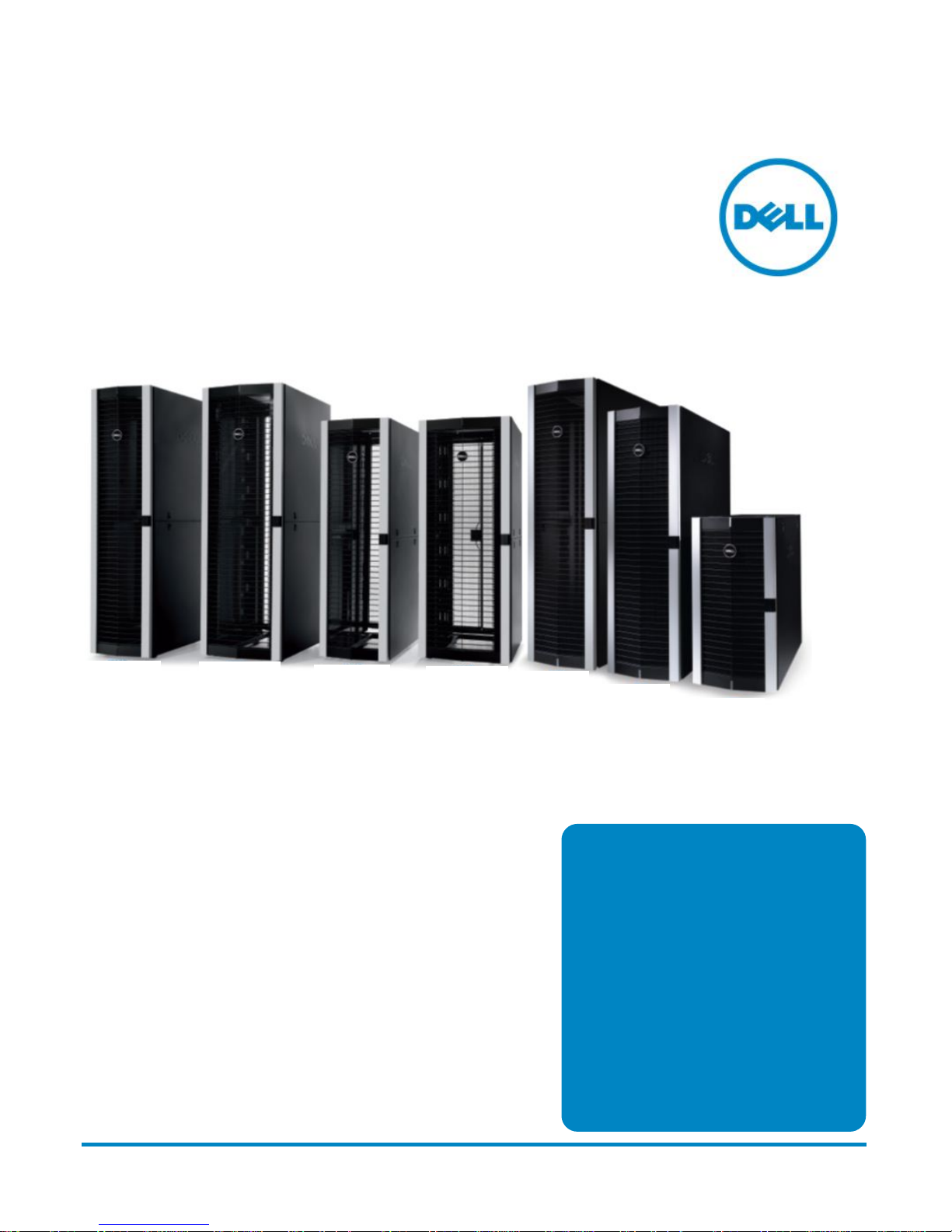
Rack Enclosures
Technical Guide
4820D
4820W
4220D
4220W
4820
4220
2420
Dell PowerEdge
2420, 4220, and 4820
An expanded
portfolio of rack
enclosures designed
to meet the
requirements of your
data center today
and tomorrow.
Page 2

This document is for informational purposes only and may contain typographical errors and technical
inaccuracies. The content is provided as is, without express or implied warranties of any kind.
Dell, the DELL logo, the DELL badge, EqualLogic, PowerEdge, PowerVault, PowerConnect, and ReadyRails are
trademarks of Dell, Inc. Other trademarks and trade names may be used in this document to refer to either the
entities claiming the marks and names or their products. Dell disclaims proprietary interest in the marks and
names of others.
©Copyright 2012 Dell Inc. All rights reserved. Reproduction or translation of any part of this work beyond that
permitted by U.S. copyright laws without the written permission of Dell Inc. is unlawful and strictly forbidden.
September 2012 | Version 2.0
ii PowerEdge Rack Enclosures Technical Guide
Page 3

Table of contents
1 System overview ..................................................................................................................................................................5
Introduction .........................................................................................................................................................................5
Benefits .................................................................................................................................................................................5
2 Rack enclosure features ..................................................................................................................................................... 7
Enclosure specifications .................................................................................................................................................... 7
Comparison of PowerEdge rack enclosures ................................................................................................................ 8
3 Rack enclosure views and features ................................................................................................................................. 9
PowerEdge 2420 rack enclosures .................................................................................................................................. 9
PowerEdge 4220 and 4820 rack enclosures ............................................................................................................. 10
Rack interior features ....................................................................................................................................................... 15
4 Thermal and airflow considerations ..............................................................................................................................18
Thermal and airflow features ..........................................................................................................................................18
5 Installing rack enclosures ................................................................................................................................................ 19
Adjustable mounting posts ............................................................................................................................................. 19
Dell ReadyRails and ReadyRails II ................................................................................................................................... 19
Cable management arm (CMA) ..................................................................................................................................... 21
6 Rack kit accessories ......................................................................................................................................................... 22
Thermal solutions ............................................................................................................................................................ 22
Power solutions ............................................................................................................................................................... 23
Management solutions ................................................................................................................................................... 24
Additional accessories .................................................................................................................................................... 26
Accessory compatibility table ........................................................................................................................................ 27
7 Rack packaging options .................................................................................................................................................. 28
8 Mechanical drawings ....................................................................................................................................................... 29
Appendix A. Regulatory certifications .......................................................................................................................... 36
Appendix B. Documentation and resources .............................................................................................................. 37
Tables
Table 1. Benefits....................................................................................................................................................................5
Table 2. Basic rack specifications ...................................................................................................................................... 7
Table 3. Rack features and specifications ........................................................................................................................ 7
Table 4. Comparison of PowerEdge rack enclosures ................................................................................................... 8
Table 5. Blanking panel options ...................................................................................................................................... 22
Table 6. Rack accessories for Dell rack enclosures ..................................................................................................... 27
Table 7. Packaging options for Dell rack enclosures .................................................................................................. 28
Table 8. Additional resources .......................................................................................................................................... 37
Figures
Figure 1. Front, rear, and frame views of the 2420 rack enclosure ............................................................................. 9
Figure 2. Top view of the 2420 rack enclosure ............................................................................................................. 10
Figure 3. Front view and features ..................................................................................................................................... 10
Figure 4. Back view of the 4220 rack enclosures .......................................................................................................... 11
Figure 5. Back view of the 4820 rack enclosures .......................................................................................................... 12
Figure 6. Side view of the 4220 rack enclosures ............................................................................................................ 12
Figure 7. Side view of the 4820 rack enclosures ........................................................................................................... 13
Figure 8. Top view of the rack enclosures ......................................................................................................................14
Figure 9. Tail bar access for cables ................................................................................................................................... 15
iii PowerEdge Rack Enclosures Technical Guide
Page 4

Figure 10. Vertical- mount power distribution unit trays ................................................................................................. 16
Figure 11. Casters and leveling feet .................................................................................................................................... 16
Figure 12. Stabilizer feet ........................................................................................................................................................ 17
Figure 13. Front, side, and rear latches and locks ............................................................................................................ 17
Figure 14. Adjustable vertical mounting posts .................................................................................................................. 19
Figure 15. ReadyRails II and ReadyRails mounting kits................................................................................................... 20
Figure 16. Cable management arm .................................................................................................................................... 21
Figure 17. External dimensions – 4820 rack enclosure ................................................................................................. 29
Figure 18. External dimensions – 4220 rack enclosure ................................................................................................. 29
Figure 19. External dimensions – 2420 rack enclosure ................................................................................................. 30
Figure 20. Internal dimensions – 2420, 4220, 4820 (top and bottom views) ........................................................... 30
Figure 21. Internal dimensions – 2420, 4220, 4820 (leveling foot/minimum clearance) ........................................ 31
Figure 22. External dimensions – 4820D rack enclosure ............................................................................................... 31
Figure 23. External dimensions – 4220D rack enclosure .............................................................................................. 32
Figure 24. Internal dimensions – 4220D and 4820D (top and bottom views) .......................................................... 32
Figure 25. Internal dimensions – 4220D and 4820D (leveling foot/minimum clearance) ..................................... 33
Figure 26. External dimensions – 4820W rack enclosure ............................................................................................. 33
Figure 27. External dimensions – 4220W rack enclosure ............................................................................................. 34
Figure 28. Internal dimensions – 4220W and 4820W (top and bottom views)......................................................... 34
Figure 29. Internal dimensions – 4220W and 4820W (leveling foot/minimum clearance) .................................... 35
iv PowerEdge Rack Enclosures Technical Guide
Page 5

1 System overview
Introduction
The Dell™ PowerEdge™ rack enclosures are designed to hold and protect server, network and data
storage equipment. The Dell rack is a sturdy, practical design and solidly built, delivered with
Enterprise service, support and reliability. The Dell PowerEdge rack enclosures are offered in three
height options: 24U (2420), 42U (4220), and 48U (4820); each of these racks is available in the
standard 600mm x 1070mm dimensions, to fit within a two-tile floor plan layout.
Dell has introduced both wide and deep versions of the PowerEdge rack enclosures to address
specific market requirements for additional space for power and cable management. The 42U and
48U heights are available in the wide form factor, 750mm wide x 1070mm deep, and the deep form
factor, 600mm wide x 1200mm deep. The Dell racks are complemented with a range of products
that include basic, metered, and managed power distribution units (PDUs), rack- mount
uninterruptible power supplies (UPSs), digital keyboard/video/monitors (KVMs), and other
accessories.
All of these form factors adhere to the EIA- 310- E standard for rack mounting of electronics,
ensuring that the mounting posts for installing components are configured for 19- inch equipment,
while the exterior of the rack is set to the specified dimensions. This ensures compatibility with
existing equipment while providing more options for cable and power cord routing. Not only do Dell
PowerEdge servers fit in these 19-inch racks, but other Enterprise equipment fit as well, including
Dell PowerVault™ and Dell EqualLogic™ storage, and Dell PowerConnect™ networking switches,
plus routers, hubs, and telephony equipment. Built with adjustable vertical mounting posts within
the rack, Dell racks are designed for use in almost any environment, such as an Enterprise data
center, a high-performance computing center, a remote office, a wiring closet, or a factory floor.
Benefits
Table 1 lists the benefits of the rack enclosures.
Table 1. Benefits
Benefits Detailed descriptions
Height options Dell PowerEdge rack enclosures offer three height options: 24U, 42U, and 48U
Form factors 42U and 48U are available in standard, wide, and deep form factors
Door design Excellent airflow with 80% perforated doors
Cabling and PDUs Superb design facilitates more cabling and power distribution options
With a static load rating of 2,500 lbs and three form factors to choose from, the PowerEdge 42U
and 48U rack enclosures can provide the capacity you need to hold a full complement of data
center equipment. These sizes are available in three form factors:
• Standard: 600mm wide x 1070mm deep
• Wide: 750mm wide x 1070mm deep
• Deep: 600mm wide x 1200mm deep
5 PowerEdge Rack Enclosures Technical Guide
Page 6

Wide (750mm) racks in both 42U and 48U heights have three inches more space on each side for
cables and PDUs for networking, blade server and other installations that need to route cables along
the sides. The wide design of the 4820W and 4220W also moves the PDU trays even farther away
from the rack mounting posts, allowing more room for cables in the sides and back, helping reduce
contention between power cords, cables and installed equipment.
Deep (1200mm) racks offer more space in the back for cables and PDUs for high- density
installations. The 4820D and 4220D racks have extended PDU trays in the back of the rack, which
can hold up to four vertical- mount full-height PDUs on each side. This extra space can be used for
additional power management or for routing cables. PDUs can also be mounted with a 90-degree
rotation so that the power cords point toward the back of the rack rather than toward the middle.
6 PowerEdge Rack Enclosures Technical Guide
Page 7

2 Rack enclosure features
Table 2 contains the basic specifications for the rack dimensions and weights, while Table 3 provides
more details on features and specifications for the rack enclosures.
Enclosure specifications
Table 2. Basic rack specifications
Dimensions
Standard rack
enclosure
Deep rack
enclosure
Wide rack
enclosure
PowerEdge 4820
48U rack enclosure
Height 89.5" (2273mm)
Width 23.8" (605mm)
Depth 42.1" (1070mm)
Weight 315 lbs (143 kg)
Height 89.5" (2273mm)
Width 23.8" (605mm)
Depth 47.2" (1200mm)
Weight 342 lbs (155 kg)
Height 89.5" (2273mm)
Width 29.8" (755mm)
Depth 42.1" (1070mm)
Weight 351 lbs (159 kg)
PowerEdge 4220
42U rack enclosure
Height 78.7" (1999mm)
Width 23.8" (605mm)
Depth 42.1" (1070mm)
Weight 298 lbs (135 kg)
Height 78.7" (1999mm)
Width 23.8" (605mm)
Depth 47.2" (1200mm)
Weight 318 lbs (144 kg)
Height 78.7" (1999mm)
Width 29.8" (755mm)
Depth 42.1" (1070mm)
Weight 335 lbs (152 kg)
Table 3. Rack features and specifications
Features Rack technical specifications
• Static load rating of 2,500 lbs for 48U/42U and 1,500 lbs for 24U
• Large open base for cable entry and exit
• Rack- top cable exits with adjustable, sliding door and removable tail bar
• Reversible front door can be configured to open from left or right, with lock
• Dual rear doors with lock (same key as front door)
• Split side panels, with locks (same key as doors)
• Removable front and rear doors have an 80% open perforation pattern to aid
Rack form factor
in thermal management
• Reinforced frame for stability
• Adjustable square- hole EIA mounting posts can be positioned forward or
backward within the rack
• U-space numerical markings on both front and rear mounting posts
• Rear- mount vertical PDU trays
• Rotating rear casters to easily position rack
• Easily accessible leveling feet
PowerEdge 2420
24U rack enclosure
Height 47.3" (1202mm)
Width 23.8" (605mm)
Depth 42.1" (1070mm)
Weight 209 lbs (95 kg)
Rack color Black with aluminum accents
Products supported
7 PowerEdge Rack Enclosures Technical Guide
All Dell and third- party rack- mount equipment compliant to the EIA-310- E
standard
Page 8

Features Rack technical specifications
Shipping options
Standard ground shipping pallet
Air freight container
Comparison of PowerEdge rack enclosures
Table 4 compares the basic specifications of the rack enclosure portfolio.
Table 4. Comparison of PowerEdge rack enclosures
Features Dell 2420 Dell 4220/4820 Dell 4220W/4820W Dell 4220D/4820D
U Spaces 24U 42U/48U 42U/48U 42U/48U
Height (mm) 1202 1999/2273 1999/2273 1999/2273
Width (mm) 605 605 755 605
Depth (mm) 1070 1070 1070 1200
Static load
capacity
Vertical PDU
capacity
1500 pounds 2500 pounds 2500 pounds 2500 pounds
Up to 4 HH
1
Up to 4 FH
2
Up to 8 HH
Up to 4 FH
Up to 8 HH
Up to 8 FH
Up to 16 HH
0U access Limited Limited Improved Limited
1
Half- height
2
Full- height
8 PowerEdge Rack Enclosures Technical Guide
Page 9
3 Rack enclosure views and features
The Dell PowerEdge rack enclosures provide important power distribution, cooling and cabling
options for a range of Enterprise environments, including high density installations such as HPC and
newer/reconfigured data centers where the facilities are equipped to support higher thermal and
power loads per rack.
All Dell racks offer enhanced power management, efficient cooling, and simplified component
mounting and storage for a wide range of IT equipment. The PowerEdge 4820 rack enclosure is
designed for high-density data centers where floor space is at a premium. The PowerEdge 4220
rack enclosure is designed to provide Enterprise efficiency for all sizes of data centers, while the
PowerEdge 2420 rack enclosure provides a compact option.
PowerEdge 2420 rack enclosures
The PowerEdge 2420 rack enclosure is very similar to its larger family members, but does have
some specific differences.
• Most noticeably, the rack is 24U high, providing a compact enclosure for smaller data rooms.
• The static load capacity of the 24U rack is 1,500 pounds.
• The top canopy is not perforated, thereby providing a solid surface on the top of the rack.
• The lower height accommodates up to four of the half- height vertical PDU offerings.
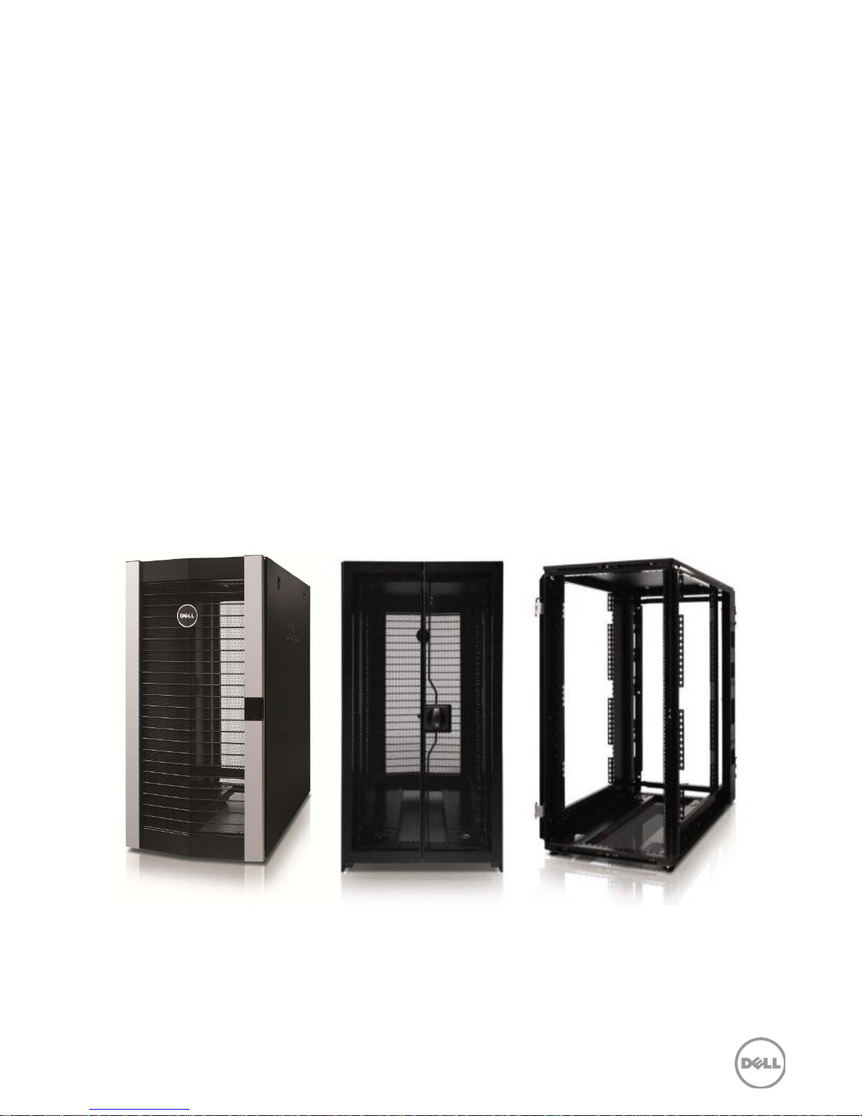
Figure 1 and Figure 2 show the various external views specific to the 2420 rack enclosure.
Front Rear Frame
Figure 1. Front, rear, and frame views of the 2420 rack enclosure
9 PowerEdge Rack Enclosures Technical Guide
Page 10
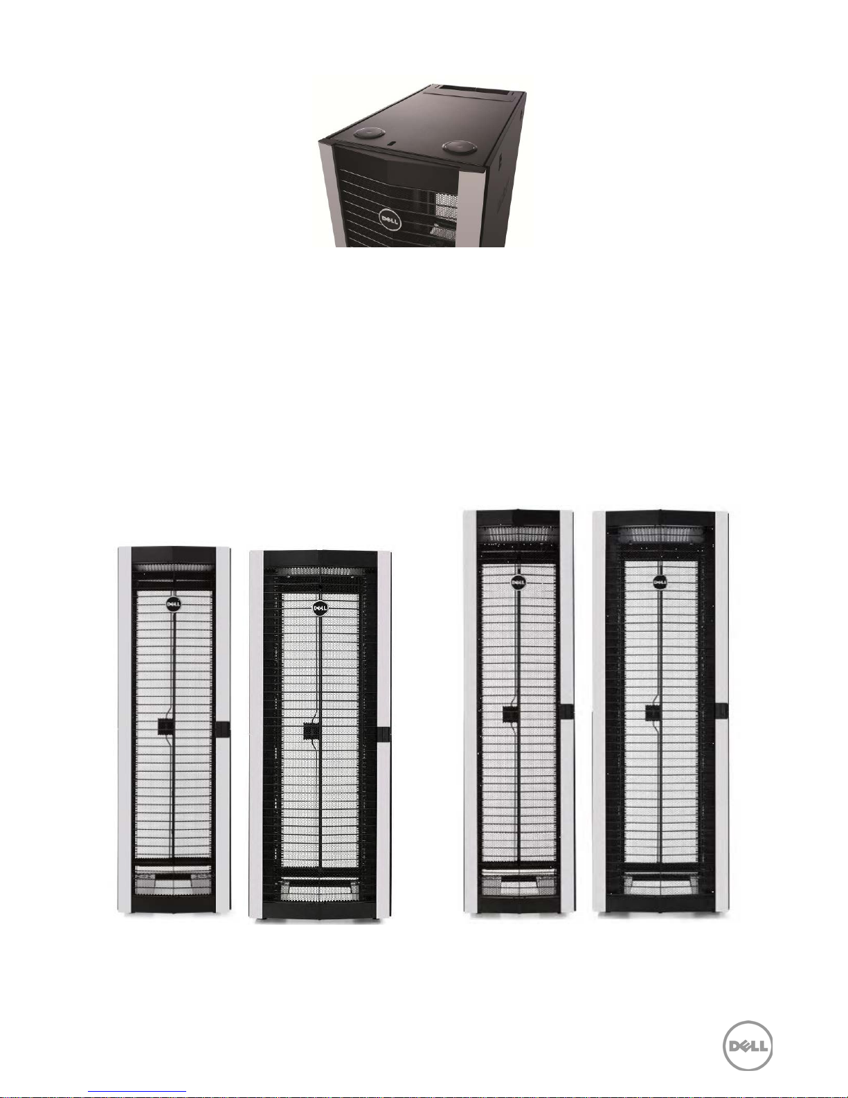
Figure 2. Top view of the 2420 rack enclosure
PowerEdge 4220 and 4820 rack enclosures
The PowerEdge 4220 and 4820 rack enclosures have identical features except the 4820 rack
enclosure adds 6U of height.
• 42U and 48U heights are available in standard (600mm x 1070mm), wide (750mm x
1070mm) and deep (600mm x 1200mm) form factors.
• Static load capacity of the 42U and 48U racks is 2,500 pounds.
• Top canopy is perforated, providing a path for airflow through the top of the rack.
The following sections and figures show the various external views specific to the 4220 and 4820
rack enclosure options.
4220, 4220D 4220W 4820, 4820D 4820W
Figure 3. Front view and features
10 PowerEdge Rack Enclosures Technical Guide
Page 11
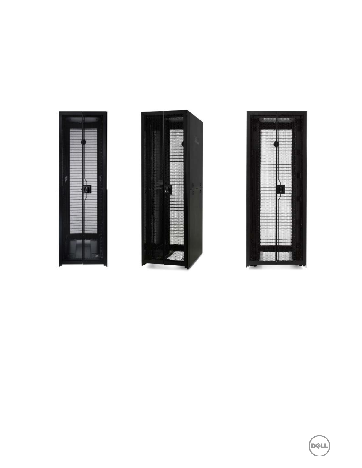
The wide and deep racks have the same design style as the standard 4220 and 4820 racks. In fact,
the deep racks look the same as the standard racks in a straight- on front or back exterior view, but
the extended depth can be seen in a side view. The additional 3 inches added on each side of the
wide rack are noticeable in the front and rear view of the rack, but from the side, the wide racks look
the same as the standard racks.
Dell rack enclosures have faster and easier access to the rear of rack with a single latch for both
doors. All of the 42U and 48U racks have two-piece side panels for easier removal and access to the
sides of the IT equipment and cables, as well as a split rear door design that includes a single latch
mechanism.
4220 4220D 4220W
Figure 4. Back view of the 4220 rack enclosures
11 PowerEdge Rack Enclosures Technical Guide
Page 12
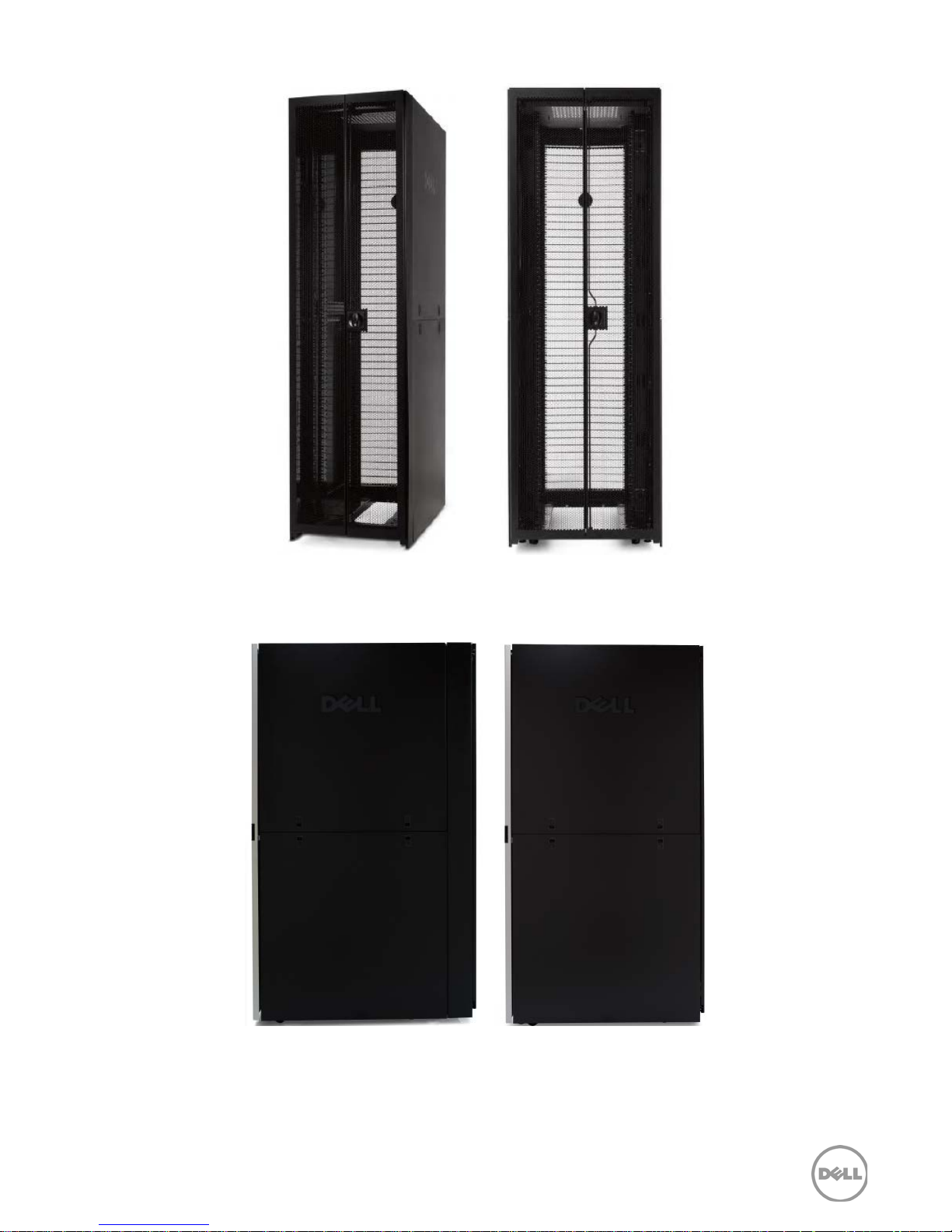
4820D 4820W
Figure 5. Back view of the 4820 rack enclosures
4220D 4220, 4220W
Figure 6. Side view of the 4220 rack enclosures
12 PowerEdge Rack Enclosures Technical Guide
Page 13
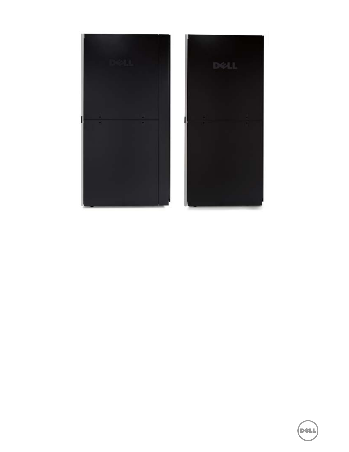
Figure 7. Side view of the 4820 rack enclosures
4820D 4820, 4820W
13 PowerEdge Rack Enclosures Technical Guide
Page 14
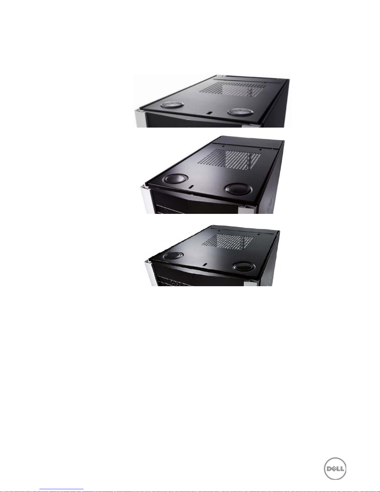
Top canopy knock- outs and adjustable rear- of-rack sliding cable exit door enable cabling from
above. The rack’s large open base and removable side panels offer more options for cable access.
The basic design of the canopy is similar between the three form factors, as shown in Figure 8.
Standard
Deep
Wide
Figure 8. Top view of the rack enclosures
14 PowerEdge Rack Enclosures Technical Guide
Page 15
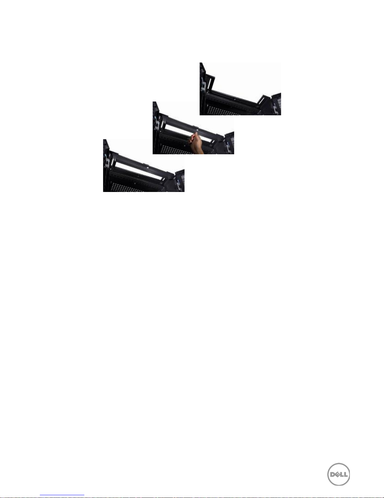
Removable “tail- bars” at both top and bottom of the rear of the rack, shown in Figure 9, make
cabling the IT equipment easier, especially in highly dense environments with three-phase power
cables deployed. The bars can be re-attached after the cables are in place.
Figure 9. Tail bar access for cables
Rack interior features
Each of the PowerEdge rack enclosure form factors accommodates servers with deep chassis
dimensions while allowing space for power and cable management.
PDU trays
In addition to U- space PDU mounting, the PowerEdge rack enclosures have specially designed trays
inside the rear doors to easily mount vertical PDUs, without using any tools, so they won't interfere
with air circulation. These trays are positioned as far back and out from the rear of the equipment as
possible, to reduce contention with cable management arms and equipment with removable
components. The PDU tray design provides more options for mounting various PDU types, and
provides access to the square holes in the rear frame posts for additional cable management
options. Dell vertical mount PDUs are available in a number of sizes and can be combined within a
rack. For more information, see the Rack kit accessories section.
Deep racks have expanded PDU trays in the back of the rack, which can be used for additional
power management or for routing cables. Wide racks have extra distance between the mounting
posts and the sides of the racks, moving the PDU trays even farther away from the rack’s mounting
posts and the equipment installed in the rack, which reduces interference between installed
equipment and cables. The trays in the standard and wide racks can hold up to four full-height or
eight half- height units while the deep rack trays can accommodate twice as many.
Note the clearly labeled U markings on the mounting posts for easier installation and service;
markings are provided on both the front and rear mounting posts.
Cable management clips are available for routing cables along the rear mounting posts.
15 PowerEdge Rack Enclosures Technical Guide
Page 16
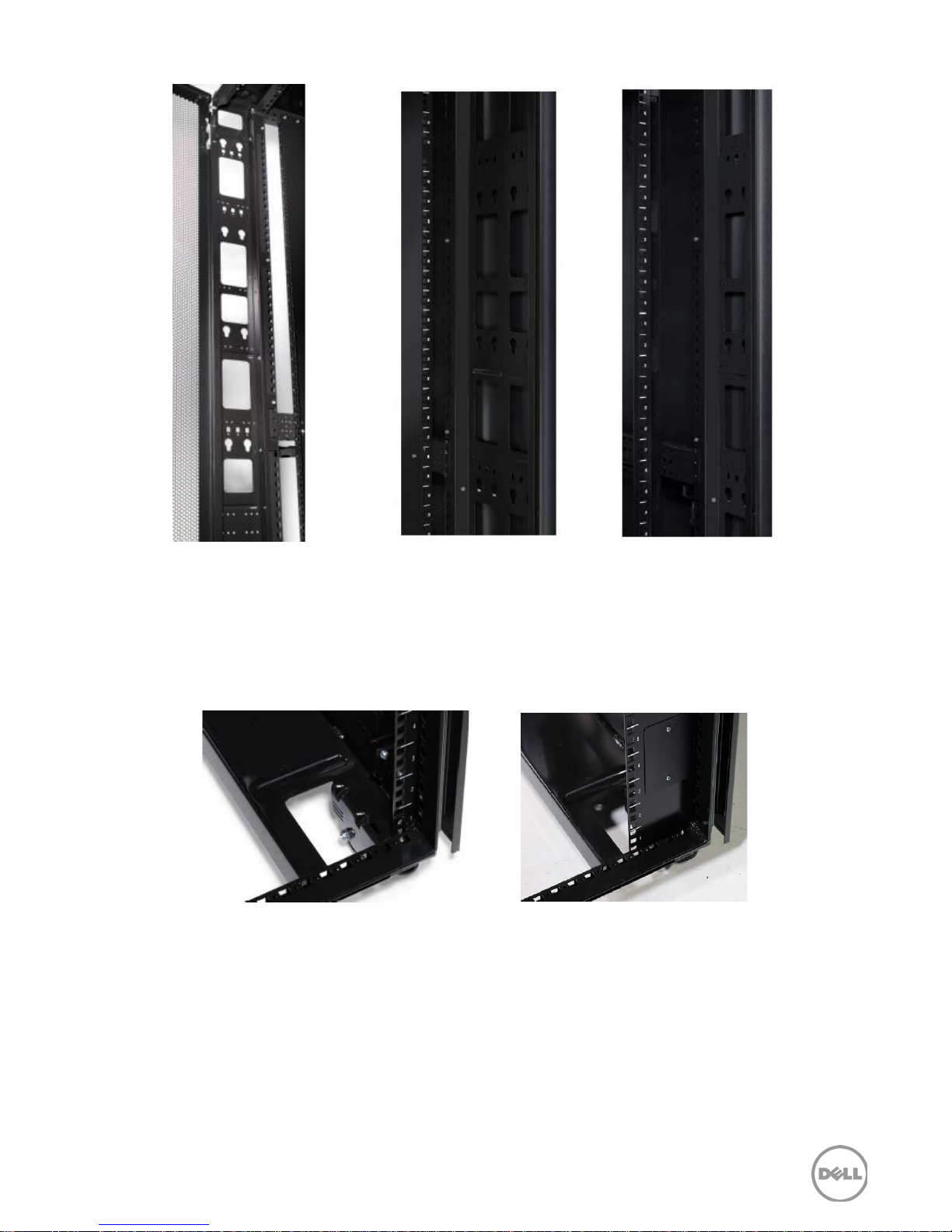
Standard Deep Wide
Figure 10. Vertical-mount power distribution unit trays
Rack stability and security
Each rack includes rotating rear casters for better maneuverability when positioning the rack in the
data center. The leveling feet are easily accessible to facilitate firm placement.
Standard / Deep Wide
Figure 11. Casters and leveling feet
Stabilizer feet, included with the rack, attach to the front and sides of each rack enclosure for
increased stability. Stabilizer feet have an “open face” to allow cold air to pass through and also have
holes to attach the stabilizer feet to the floor. Stabilizer feet should be attached to the front and both
sides of a stand-alone rack. Interconnect kits are available to link adjacent rack enclosures for
increased stability.
16 PowerEdge Rack Enclosures Technical Guide
Page 17
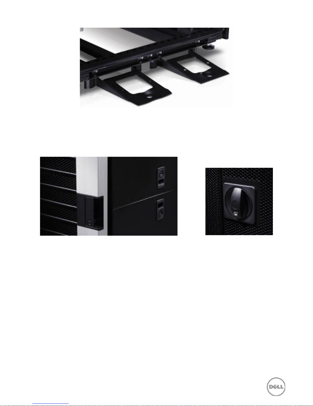
Figure 12. Stabilizer feet
Lockable side panels and front and rear doors provide security for data centers, remote offices,
wiring closets, factory floors and other server environments. Front and rear door locks and side
panel locks are keyed alike for easier opening; different lock sets can be provided through Dell S&P
if needed.
Figure 13. Front, side, and rear latches and locks
17 PowerEdge Rack Enclosures Technical Guide
Page 18

4 Thermal and airflow considerations
Dell rack enclosures are designed for maximum airflow and the reduction of thermal issues, which
means greater efficiency and power savings for your data center.
Thermal and airflow features
The front and rear doors have 80% perforation to allow air to move through the rack with minimal
resistance, and flexible air dams help keep hot air from recirculating from the back to the front,
alleviating a problem common in many racks. Dell’s wide rack enclosure employs extended air dams
across the front to ensure proper airflow containment. Available blanking panels can further manage
airflow by filling unused U- space in the rack; see the Rack kit accessories section for information on
thermal accessories.
For hot- aisle/cold-aisle thermally- efficient data center topologies, the standard rack enclosure fits
within two standard floor tiles, in a space approximately 2 feet wide x 3.5 feet deep. The 750mm
wide rack is slightly wider and the 1200mm deep rack is slightly deeper. Space planners can select
the form factor that best meets data center needs.
18 PowerEdge Rack Enclosures Technical Guide
Page 19
5 Installing rack enclosures
Dell rack enclosures are compliant to EIA/ECA-310- E and IEC 60297-3- 100 design specifications.
Dell racks use the square-hole design and are compatible with Dell and third-party rack-mount
systems.
Adjustable mounting posts
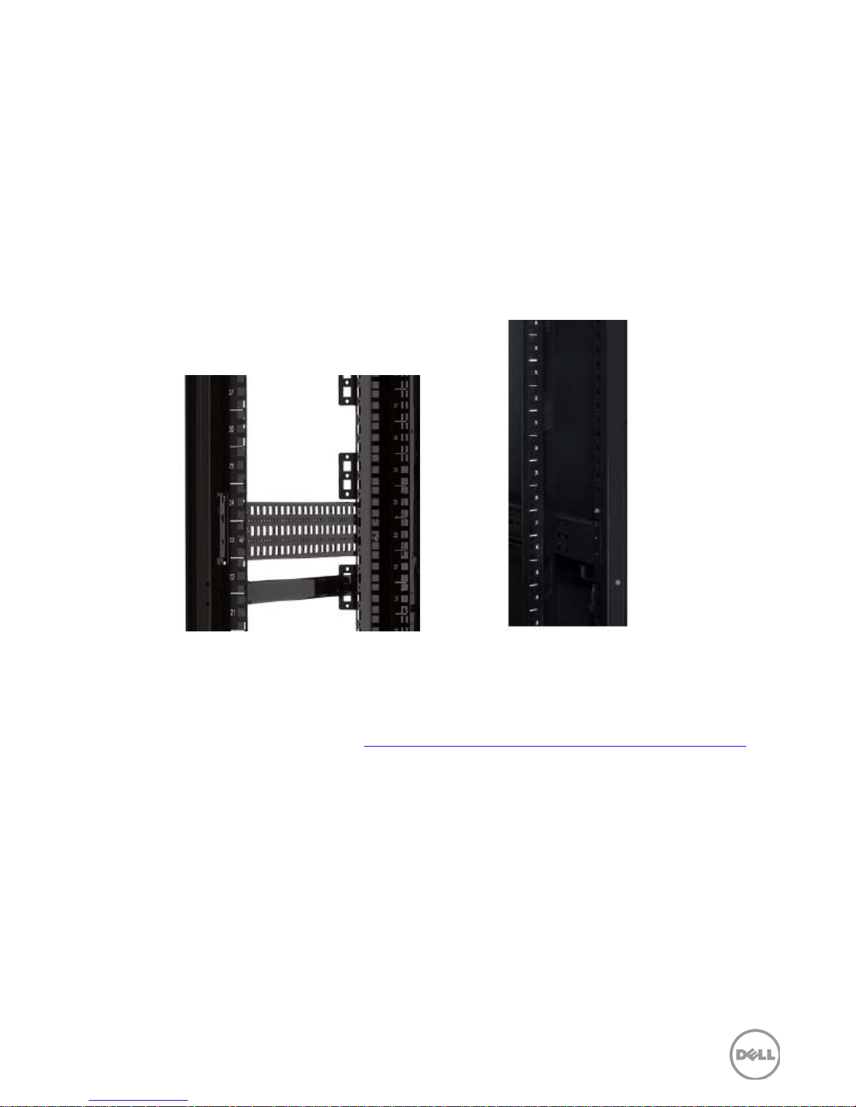
Dell racks have four adjustable vertical mounting posts to enable flexibility of the location of IT
equipment within the rack; this allows devices to be positioned closer to the front door or to the
rear door. These posts are positioned at 29 inches apart, but can be adjusted from 24 to 30 inches.
The front air dam seal can be maintained within 2 inches of adjustment.
Figure 14. Adjustable vertical mounting posts
For information regarding proper installation and cabling techniques for the Dell racks and servers,
please refer to
Cabling Best Practices
related documentation may be found at: http://support.dell.com/support/edocs/systems/racks/
the Rack Installation and Cable Management Arm Installation Instructions and
for the appropriate server model. Additionally, rack installation guides and
.
Dell ReadyRails and ReadyRails II
The rails and cable management solutions for Dell 11th and 12th generation server platforms have
slam
been designed to enable the user- friendly
automatically) on the chassis, to expand third-party rack compatibility and to improve the overall
customer experience. The efficient design makes the release latch visible and accessible from the
front of the rack, with no special tools or empty U- spaces above or below required to disengage,
making the rails equally easy to remove.
th
Dell 11
tool- less mounting in EIA-310- E compliant square hole and unthreaded round-hole 4- post racks.
Dell’s server, storage, and networking systems can be easily installed into the Dell PowerEdge 4820,
4220, and 2420 rack enclosures using the Dell ReadyRails static and sliding rail kits. Static rail kits
can be mounted, with a minor conversion using tools, into 4- post threaded hole racks and 2- post
generation server rails include the simple and intuitive ReadyRails™ rack/rail interface for
latches (spring- loaded latches that engage
19 PowerEdge Rack Enclosures Technical Guide
Page 20
racks. Sliding rails require an adapter bracket for installation in threaded-hole racks. Other products
including rack-mount UPS systems, KVMs, and the 1U equipment shelf also use the ReadyRails
interface.
th
With the 12
generation servers, the rack/rail interface for the sliding rails has been updated to the
ReadyRails™ II design, which provides native support (with simple conversion) for threaded-hole
racks. ReadyRails and ReadyRails II rail kits are extremely fast and easy to deploy and are as easy to
remove from the rack as they are to install.
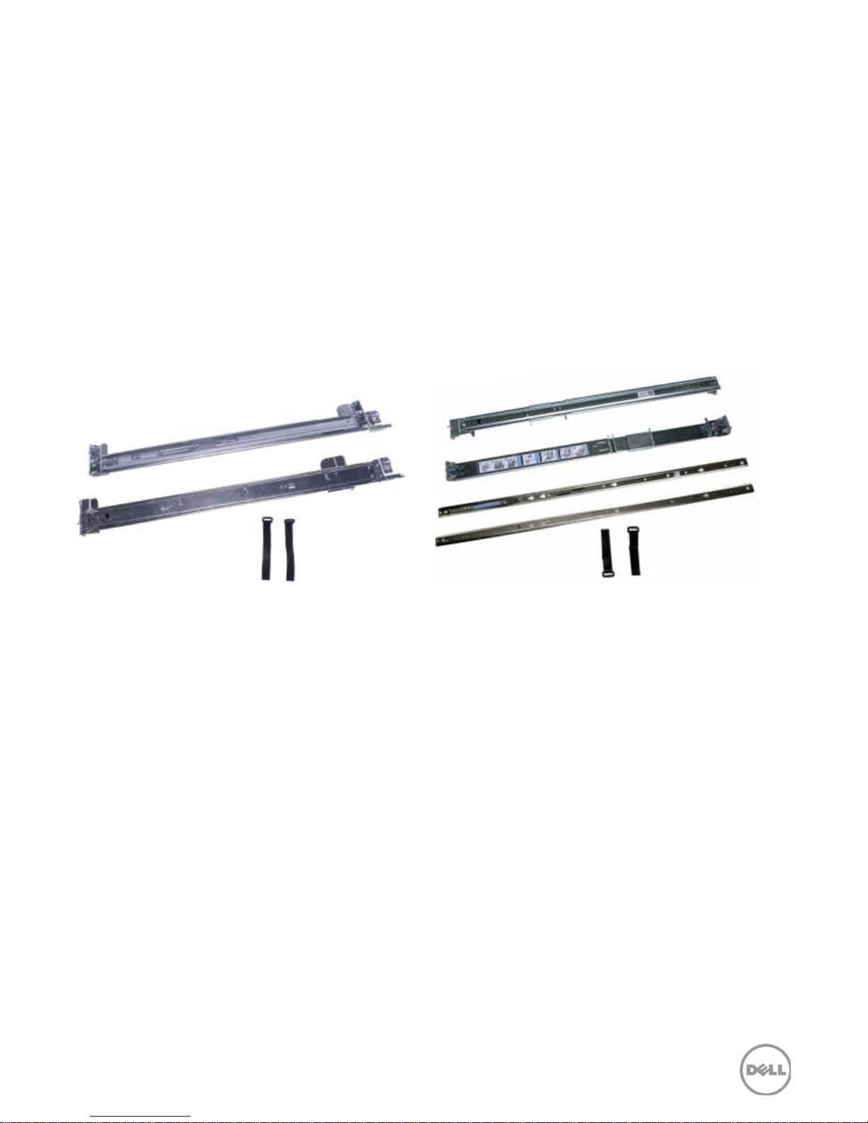
The rail kits are available in either sliding or static style, based on the system specifications and the
customer’s needs. Sliding rails allow the system to be fully extended out of the rack for service and
have an optional cable management arm (CMA) that provides a guide for component cable routing
to the rear of the rack. Static rails support a wider variety of racks than the sliding rails but do not
support serviceability in the rack. Due to their reduced complexity and lack of need for CMA
support, the static rails offer a smaller footprint than the sliding rails.
Sliding Static
Figure 15. ReadyRails II and ReadyRails mounting kits
20 PowerEdge Rack Enclosures Technical Guide
Page 21
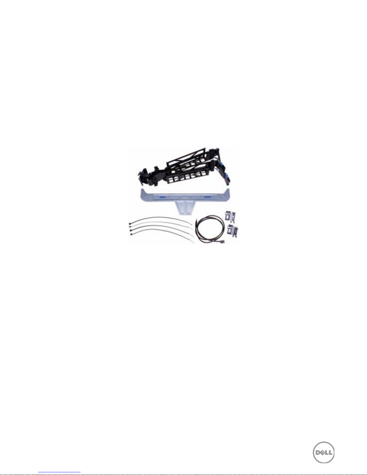
Cable management arm (CMA)
The optional cable management arm (CMA) for the sliding rails organizes and secures the cords and
cables exiting the back of the server and unfolds to allow the server to extend out of the rack for
service without having to detach the cables. Key features of the CMA shown in Figure 16 include:
• Large U- shaped baskets to support dense cable loads
• Open vent pattern for optimal airflow
• Fully reversible (can be mounted on either side) with no conversion required
• Uses hook- and- loop straps rather than plastic tie wraps to eliminate the risk of cable damage
during cycling
• Includes a low profile fixed tray to both support and retain the CMA in its fully closed position
• Both the CMA and the tray mount without the use of tools with intuitive snap-in designs
Figure 16. Cable management arm
21 PowerEdge Rack Enclosures Technical Guide
Page 22

6 Rack kit accessories
Dell offers thermal, power, and management rack solutions as well as optional rack accessories
designed for maximum compatibility with a wide array of rack enclosure configurations.
Thermal solutions
In order to help with proper air flow in the rack and improve cooling efficiency, Dell offers optional
rack fan kits and blanking panels.
Blanking panels
Dell offers closeout filler panels in a variety of sizes and materials to fit in the Dell PowerEdge racks.
Closeout filler panels, also called blanking panels, provide a way to fill unused rack space in the front
of a rack, resulting in improved air flow to the installed equipment, and reducing hot air recirculation
to the front of the rack. Using closeout filler panels helps to implement data center best practices,
which lead to a common goal: creating the coldest possible intake temperature with the highest
possible volume of chilled-air delivery and the warmest possible exhaust temperature.
Plastic closeout filler panels are tool-less, and provide easy and quick snap-in installation for squarehole racks. These are available in 1U and 2U sizes.
Steel closeout filler panels provide support for more types of racks, with tooled installation for
square, round, or threaded holes. Multiple sizes are available for optimizing coverage in 1U, 2U, 3U,
or 6U increments, as listed in Table 5. Hardware with #10- 32 threads is provided to support
installation in threaded hole racks.
Table 5. Blanking panel options
Panel options Plastic Steel
Single- pack 1U, 2U 1U, 2U, 3U, 6U
10-pack 1U, 2U 1U, 2U
100- pack 1U
Square- hole
Round- hole
Threaded- hole
–
–
–
Fans
Dell offers three rack fans that can be installed in the top of the 42U and 48U racks to facilitate the
movement of air through the upper canopy. The options are 120V, 208V, and 230V to handle
different voltage requirements. The package includes the rack fan, power cable, grounding cable
and cover.
22 PowerEdge Rack Enclosures Technical Guide
Page 23

Power solutions
Dell provides the ideal PDU and UPS systems to protect and support Enterprise applications. With
three- year warranties and Dell’s world class support and reliability, the extensive portfolio of Dell
PDUs and UPSs can be mixed and matched to create the right combination for your data center
needs.
Power distribution unit
A PDU (power distribution unit) distributes power from a single input to multiple outlet receptacles.
Reliable power distribution is a key component of every data center. The Dell PDU portfolio
provides reliable power distribution in a rack enclosure from low amperage single phase circuits to
higher- power 3- phase solutions. The Dell power distribution portfolio includes basic, metered, and
managed functions, input voltages from 100 volts to 415 volts, input currents from 16 amps to 60
amps, and varying quantities of outlet types, up to 48 receptacles. In addition to the amperage
rating, Dell specifies the true measure of power consumption for the PDU in kilowatt- hours (kWH).
The Dell family of PDUs combines worldwide standard IEC power outlet connections with
regionalized input options allowing flexibility across a variety of global power infrastructures.
Detachable inlet cords on some models facilitate a wide selection of deployment options.
Dell PDUs come in several form factors. One and zero rack unit (1U/0U) PDU models can be placed
in a 1U rack space with other rack- mount equipment or in the side of some racks. Dell also offers
vertical PDUs in half-height length for all Dell racks, full- height for 42U/48U racks, and extendedheight for 48U racks, providing the flexibility to select the right PDU for the equipment in the rack.
The vertical PDUs can be installed without tools utilizing button mounting in the rear trays of the
Dell racks, with the outlets facing toward the center of the rack, or turned 90 degrees to direct the
outlets toward the back of the rack to help with cord management.
The 42U and 48U high-density vertical PDUs include a greater number of highly packed outlet
receptacles, in both basic and metered versions. These are ideal for larger deployments that will
maximize the amount of equipment installed in a rack. For example, one high- density PDU could
handle all of the power supplies in multiple blade server systems installed in one rack.
Dell Metered and Managed PDUs simplify the deployment of advanced power metering and
environmental monitoring in the data center. Real-time remote monitoring of connected loads
prevents potential overloads. User- defined alarms can warn of potential circuit overloads before
critical IT failures occur. Data logging can provide load metering and report power utilization trends,
enabling data center managers to make informed decisions on right-sizing IT environments to lower
the total cost of ownership. Users can access and configure the Dell Metered or Managed PDU with
embedded firmware through secure Web, SNMP, or Telnet interfaces, and also leverage the Dell
Management Console (DMC), which provides IT administrators a consolidated view of their
infrastructure.
Optional cord retention kits help to manage the power cords plugged into the PDU. Other
accessories for the Dell Metered and Managed PDUs include temperature, temperature/humidity,
and dry contact sensors. The dry contact port can be used for user-defined sensors, such as rack
door position, motion, light detector, and proximity sensors.
Dell PDUs are specified for a higher operating temperature of 50° Celsius (122° Fahrenheit), which is
especially important for the warmer environment in the back of the rack. The PDUs also come with
a full three- year warranty.
23 PowerEdge Rack Enclosures Technical Guide
Page 24

Uninterruptible power supply
Also available with a three- year warranty, including batteries, Dell UPS (uninterruptible power supply)
backup systems are available in line-interactive and online models in tower and rack- mount styles.
The Dell UPS protects equipment from downtime, damage and data loss due to power problems.
During a power outage, the Dell UPS backup power supplies allow you to maintain power long
enough to save data and shut down equipment properly. As an added benefit, the systems also
protect against power surges and disruptive line noise.
Each Dell UPS is rated for maximum output power expressed in Watts (W), which describes the total
load that can be managed across all receptacles. All models are built to run at up to a 97% efficiency
rating.
Dell’s line-interactive (LI) tower and rack- mount UPSs provides reliable, vital power backup of IT
equipment ranging from 500W to 5600W. LI models regulate voltage by boosting input utility
voltage up or moderating (bucking) it down as necessary before allowing it to pass to the protected
equipment— or resort to battery power.
Dell’s online (OL) high- efficiency rack- mount UPSs offer the best combination of power protection
and reliability for backup of critical IT equipment covering 2700W to 5600W by isolating equipment
from raw utility power. These models combine power back- up and power conditioning for
continuous cleaner power and protection against all power disturbances.
The internal batteries in Dell UPSs can run protected equipment for five to ten minutes (depending
on the model) at full load during a power outage, or up to triple that time if the UPS is at half load. In
that time, system administrators can gracefully shut down connected systems or transfer to
generator power. In high reliability environments where it is important to keep systems running
rather than shut them down, an optional external battery module (EBM) can extend battery runtime
three or four times for all but the smaller (500W) Tower UPS and (1000W) Rack UPS models.
Dell UPS systems come with installed management software, an advanced graphical LCD, and toolless rack mounting using the Dell ReadyRails interface. The large backlit display, available in nine
languages, allows you to easily view system status and configure UPS parameters and options,
providing a comprehensive view of the UPS status and easy navigation among functions. Remote
monitoring and DMC integration are enabled with the optional network management card, which
supports secure access from anywhere over the company LAN or the Internet, with no additional
software required. With this configuration, you can manage multiple UPSs, control multiple servers
connected to a UPS, and conduct orderly, unattended power shutdown of connected equipment.
Management solutions
Dell rack solutions include Dell keyboard, video, mouse (KVM) console switches and Dell keyboard,
monitor, mouse (KMM) consoles.
Keyboard, video, mouse switches
The Dell KVM console switches enable users to need only one keyboard, mouse, and monitor to
simultaneously access multiple servers. Similar to the Dell servers and UPS, the KVM can be easily
mounted into a 1U space in the front or back of a Dell rack using a tool-less ReadyRails kit. Dell
offers both analog and remote switches, all of which are Trade Agreement Act (TAA)- compliant.
The Dell KVM 1081AD and 2161AD server console switches (SCS) provide KVM functions at the rack
for 8 or 16 devices through one or two local ports. These analog switches offer an optional remote
access key as an upgrade. The SCS easily enables control of multiple servers from a single console.
24 PowerEdge Rack Enclosures Technical Guide
Page 25

SCS’s Virtual Media support allows servers to access storage media attached to the KVM, enabling
out- of- band file transfers and OS patch deployments. You can also:
• Connect devices with four USB 2.0 ports, and up to 16 Analog Rack Interface (ARI) ports to
access servers.
• Manage your Enterprise with two local paths (video head and Analog Console Interface (ACI))
• Quickly mount the SCS in the rack without tools thanks to the Dell ReadyRails mounting
interface
• Enforce multi- factor authentication over USB and Ethernet with the Common Access Card
capability for smart cards.
The Dell KVM 1082DS, 2162DS and 4322DS remote console switches (RCS), also called KVM over IP
switches, perform management in a heterogeneous environment for Dell and third-party servers,
serial devices, and PDUs. In addition, they help simplify server management with integrated
firmware and provide access locally in the data center and also remotely, with enhanced features
including CAC (Common Access Card) capability, true serial support, and multiple USB ports.
Users can manage Dell KVM switches and perform all KVM functions on LAN or WAN with the easyto-use client software and remote/local on-board web interface (OBWI), and easily update and
install firmware, applications, and operating systems either locally or remotely by using virtual media
(VM) or local USB.
Features and enhancements to the Dell KVM over IP switches include:
• Security: You can use CAC over USB as a general identification card and an identification
device for authorized personnel and for authentication. You can also set passwords for local
and remote access, as well as the management port. You can encrypt keyboard, mouse,
video, and VM using one of these methods: Advanced Encryption Standard (AES), 128- bit
Secure Sockets Layer (SSL), Data Encryption Standard (DES), and 3DES. Using local security,
you can set access rights and permissions for users and administrators.
• Availability: With dual Gigabit Ethernet ports and dual power supplies, Dell KVMs offer
failover redundancy for high availability environments that need to ensure that data centers
aren’t adversely affected by partial network or power outages. An external modem port
provides another means of accessing the switch if the network is compromised.
• Performance: Remote console switches provide superior remote video performance
because of the improved video compression and flexibility in configuration, even over larger
distances between console switches and server interface pods (SIPs).
• Options: The new USB 2.0 SIP provides support for full- speed VM and CAC data transfer.
The new serial SIP connects serial devices to the KVM without emulation, using the same
console. KVM functions work with all existing Dell CAT5-based PS/2, USB 1.1/2.0, and serial
SIPs.
Dell KVM over IP console switches offer a greater level of monitoring and preventive maintenance,
providing the benefits of remote server and heterogeneous datacenter management.
Keyboard, monitor, mouse console
The Dell KMM console can be connected to the KVM console switch, to provide at- the- rack visibility
to the devices connected to the KVM. This console, with a flat panel screen and an integrated
touchpad- keyboard, can be installed without tools into a 1U space in a Dell rack.
25 PowerEdge Rack Enclosures Technical Guide
Page 26

Additional accessories
Equipment shelf
For components that do not come with rails for rack-mounting installation, Dell offers the 1U fixed
equipment shelf that installs tool- lessly into square-hole or unthreaded round-hole racks using the
ReadyRails mounting interface. The rail design for the shelf also supports tooled installation in fourpost and two- post threaded- hole racks for added versatility. This steel shelf can hold up to 200
pounds of weight, and comes with a pair of hook- and- loop straps to secure cables to the shelf.
Side panels
All form factors of the 42U racks share the same two-piece side panel kit, and all form factors of the
48U racks also share a two-piece side panel kit. The deep racks also have a third side panel placed
vertically over the rear extension.
Interconnect kit
Dell provides an interconnect kit, also called a baying kit or ganging kit, that connects any two xx20
racks of the same height together. 4220 racks may also be connected to a 4210 rack using the kit.
Side panels must be removed to install the interconnect kit.
26 PowerEdge Rack Enclosures Technical Guide
Page 27

Accessory compatibility table
Table 6 provides a reference table to show which Dell rack accessories are compatible with the
various rack enclosures. The power and management accessories noted in the previous sections are
compatible with all of the offerings in this generation of racks.
Table 6. Rack accessories for Dell rack enclosures
Description 2420 4220 4220D 4220W 4820 4820D 4820W Comments
Rack Side Panel Kit for 42U racks
Deep Rack Rear Side Cover for 42U
Rack Side Panel Kit for 48U rack
Deep Rack Rear Side Cover for 48U
Rack Door Kit for 42U standard &
deep rack
deep racks
Rack Interconnect Kit
1U Static Equipment Shelf
1U Rack Blanking Panel
2U Rack Blank ing Panel
1U Rack Blanking Panel
2U Rack Blank ing Panel
3U Rack Blanking Panel
6U Rack Blanking Panel
Use with 42U rack side panel kit
4220D also requires 42U deep
rack rear side cover
4820D requires 48U deep rack
rear side cover
Use with 48U rack side panel kit
Front and Rear Doors for
600MM Rack
Not for Wide Rack
Use to attach Racks of the same
height to each other
200- lb capacity fixed shelf with
Square, Round or Threaded
Hole Support for
4- Post and 2- Post Racks
Plastic Tool- less (Snap- in)
Plastic Tool- less (Snap- in)
Steel Pack
Steel Pack
Steel Pack
Steel Pack
42U/48U Rack Mount Fan - 120V
42U/48U Rack Mount Fan - 208V
42U/48U Rack Mount Fan - 230V
Side Stabilizer Kit
27 PowerEdge Rack Enclosures Technical Guide
NOTE: Not for 24U Racks
NOTE: Not for 24U Racks
NOTE: Not for 24U Racks
Now Included with all racks
Page 28

7 Rack packaging options
Dell rack enclosures are available for ground or air shipment. Dimensions and weights for each
option are shown in Table 7.
All Dell racks can be shipped in full configuration with frame, doors, and sides, or in reduced
configuration with frame and doors. The 2420 and 4220 standard racks are also available as frame
only.
Table 7. Packaging options for Dell rack enclosures
Item
4820 Frame, Doors, Sides 143 Kg
4820 Frame, Doors 110 Kg
4820D Frame, Doors, Sides 155 Kg
4820D Frame, Doors 122 Kg
4820W Frame, Doors, Sides 159 Kg
4820W Frame, Doors 126 Kg
4220 Frame, Doors, Sides 135 Kg
4220 Frame, Doors 106 Kg
4220 Frame Only 86 Kg
4220D Frame, Doors, Sides 144 Kg
4220D Frame, Doors 116 Kg
4220W Frame, Doors, Sides 152 Kg
4220W Frame, Doors 124 Kg
2420 Frame, Doors, Sides 95 Kg
Product
weight
Weight/dimensions
ground shipment
173 Kg
2430 x 770 x 1185 (MM)
140 Kg
2430 x 770 x 1185 (MM)
188 Kg
2430 x 770 x 1315 (MM)
155 Kg
2430 x 770 x 1315 (MM)
190 Kg
2430 x 920 x 1185 (MM)
157 Kg
2430 x 920 x 1185 (MM)
164 Kg
2160 x 770 x 1185 (MM)
135 Kg
2160 x 770 x 1185 (MM)
114 Kg
2160 x 770 x 1185 (MM)
176 Kg
2160 x 770 x 1315 (MM)
148 Kg
2160 x 770 x 1315 (MM)
200 Kg
2160 x 920 x 1185 (MM)
167 Kg
2160 x 920 x 1185 (MM)
120 Kg
1362 x 770 x 1185 (MM)
Weight/dimensions
air shipment
254 Kg
2372 x 791 x 1226 (MM)
221 Kg
2372 x 791 x 1226 (MM)
317 Kg
2372 x 791 x 1356 (MM)
284 Kg
2372 x 791 x 1356 (MM)
326 Kg
2372 x 941 x 1226 (MM)
293 Kg
2372 x 941 x 1226 (MM)
225 Kg
2102 x 791 x 1226 (MM)
196 Kg
2102 x 791 x 1226 (MM)
176 Kg
2102 x 791 x 1226 (MM)
296 Kg
2102 x 791 x 1356 (MM)
268 Kg
2102 x 791 x 1356 (MM)
309 Kg
2102 x 941 x 1226 (MM)
281 Kg
2102 x 941 x 1226 (MM)
163 Kg
1304 x 791 x 1226 (MM)
28 PowerEdge Rack Enclosures Technical Guide
Page 29
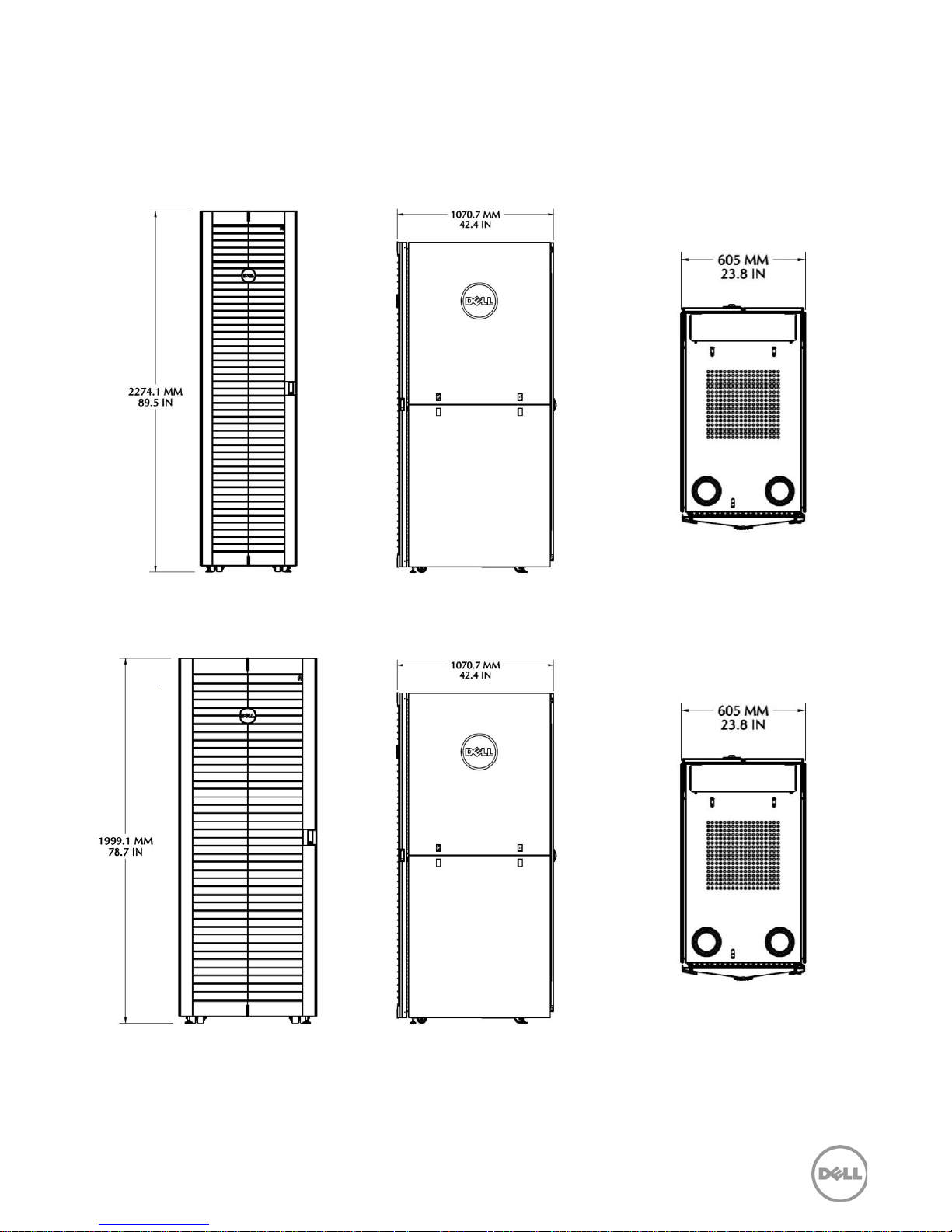
8 Mechanical drawings
This section contains the basic external and internal drawings for each of the rack form factors.
Figure 17. External dimensions – 4820 rack enclosure
Figure 18. External dimensions – 4220 rack enclosure
29 PowerEdge Rack Enclosures Technical Guide
Page 30
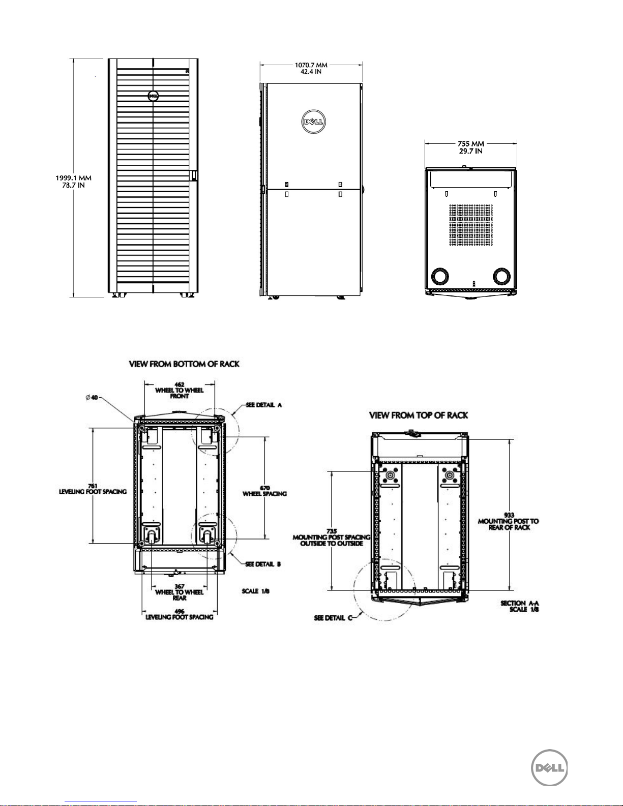
Figure 19. External dimensions – 2420 rack enclosure
Note: For Detail A, Detail B, and Detail C views, see Figure 21.
Figure 20. Internal dimensions – 2420, 4220, 4820 (top and bottom views)
30 PowerEdge Rack Enclosures Technical Guide
Page 31
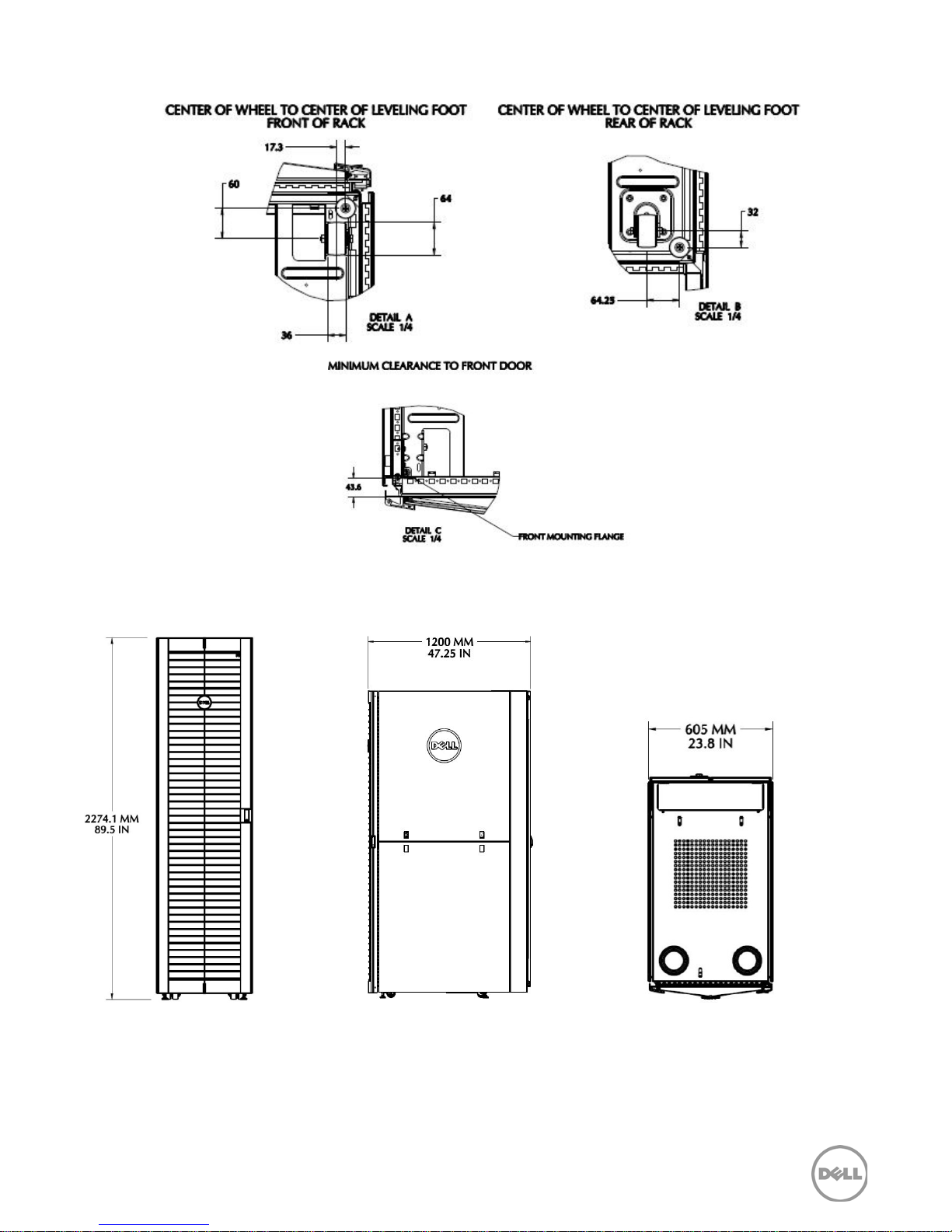
Figure 21. Internal dimensions – 2420, 4220, 4820 (leveling foot/minimum clearance)
Figure 22. External dimensions – 4820D rack enclosure
31 PowerEdge Rack Enclosures Technical Guide
Page 32
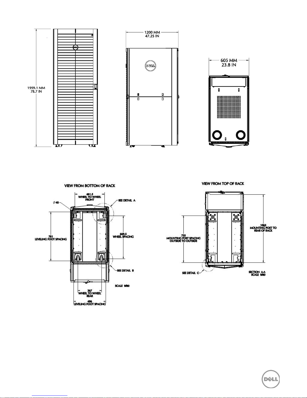
Figure 23. External dimensions – 4220D rack enclosure
Note: For Detail A, Detail B, and Detail C views, see Figure 25.
Figure 24. Internal dimensions – 4220D and 4820D (top and bottom views)
32 PowerEdge Rack Enclosures Technical Guide
Page 33
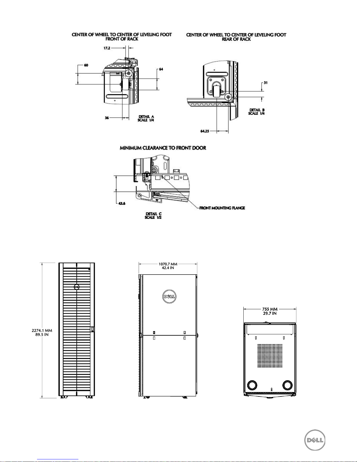
Figure 25. Internal dimensions – 4220D and 4820D (leveling foot/minimum clearance)
Figure 26. External dimensions – 4820W rack enclosure
33 PowerEdge Rack Enclosures Technical Guide
Page 34
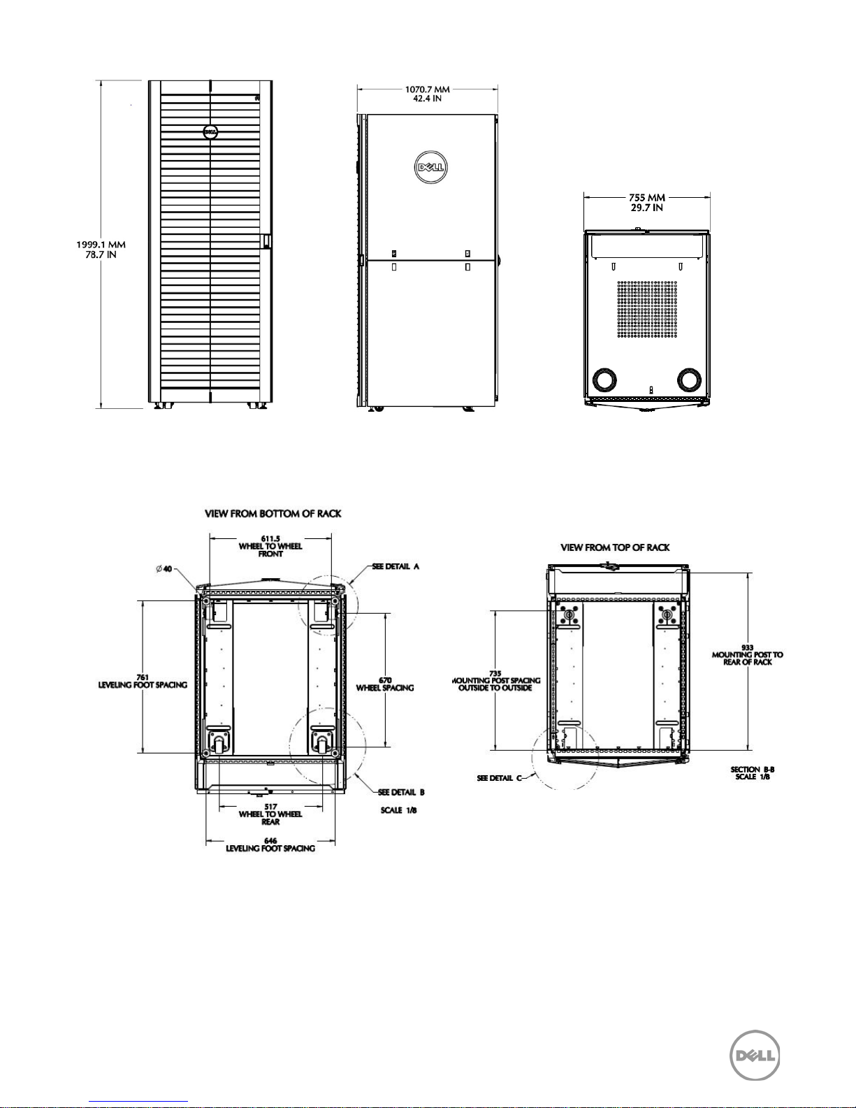
Figure 27. External dimensions – 4220W rack enclosure
Note: For Detail A, Detail B, and Detail C views, see Figure 29.
Figure 28. Internal dimensions – 4220W and 4820W (top and bottom views)
34 PowerEdge Rack Enclosures Technical Guide
Page 35
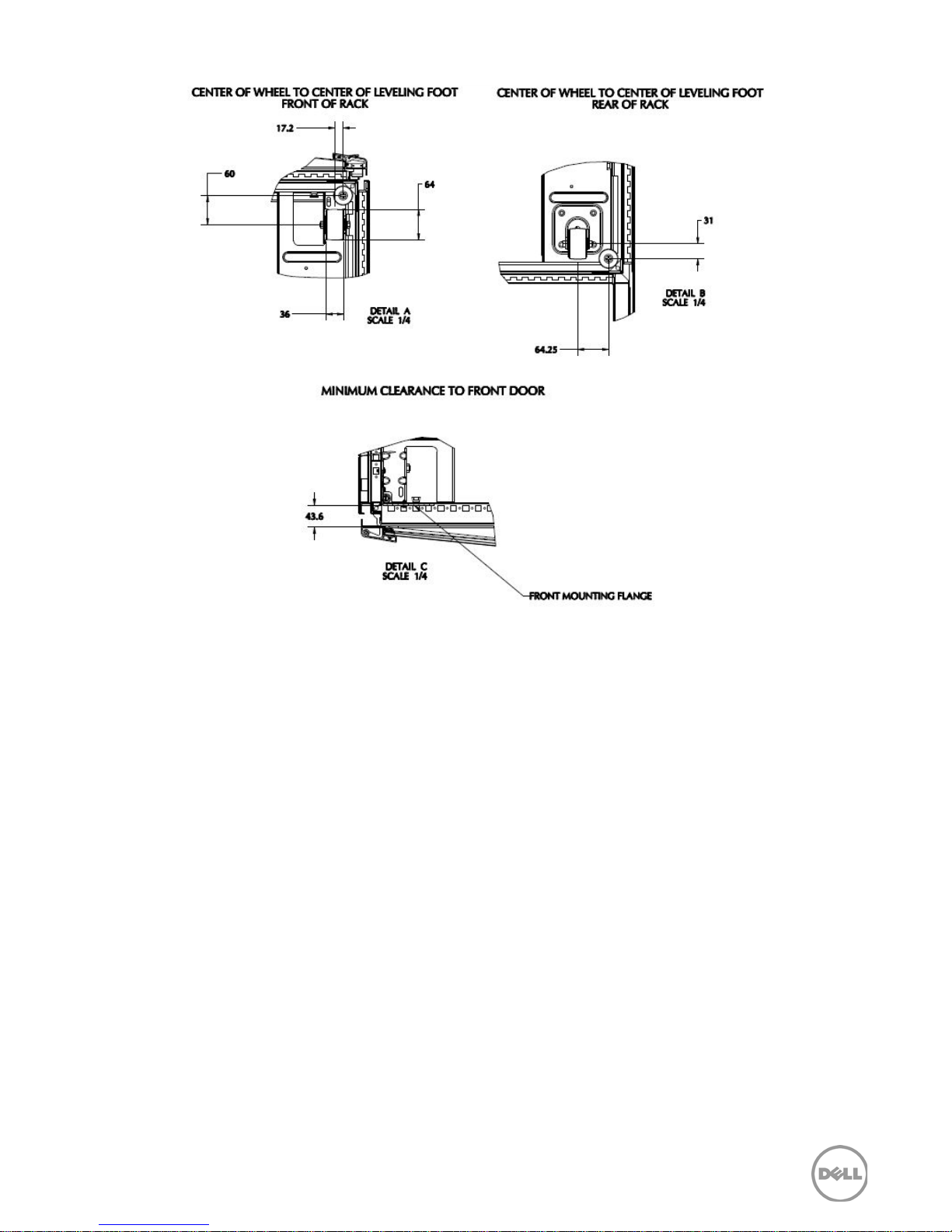
Figure 29. Internal dimensions – 4220W and 4820W (leveling foot/minimum clearance)
35 PowerEdge Rack Enclosures Technical Guide
Page 36

Appendix A. Regulatory certifications
The Dell rack enclosure meets the requirements of the Underwriters Laboratories (UL) Standard
60950-1 when properly installed according to the instructions provided in the
Guide
component is pulled out of the rack with the slide assemblies fully extended. Before installing
systems in a rack, install front and side stabilizers on stand- alone racks or the front stabilizer on
racks joined to other racks using the interconnect kit. Failure to install stabilizers accordingly before
installing systems in a rack could cause the rack to tip over, potentially resulting in bodily injury
under certain circumstances. Therefore, always install the stabilizers before installing components in
the rack.
Dell racks meet the specifications of American National Standards Institute (ANSI), Electronic
Component Association (ECA) Standard EIA/CEA- 310- E, International Electrotechnical Commission
(IEC) 60297- 3-100, and Deutsche Industrie Norm (DIN) 41494 for rack- mounting of equipment.
. The stabilizer feet help prevent the rack from tipping over when a system or other
Rack Installation
36 PowerEdge Rack Enclosures Technical Guide
Page 37

Appendix B. Documentation and resources
Installing the Optional Fan Kit in a Dell PowerEdge
A single
Rack Installation Guide
is provided in the packaging for all Dell rack enclosures. Please refer
to this document for details on removing and replacing the doors and side panels.
You can also find rack installation guides and helpful white papers at the following
location: http://support.dell.com/support/edocs/systems/racks/en/index.htm. Table 8
comprehensive list of rack enclosure documentation.
Table 8. Additional resources
Resource Description of contents Location
Dell Energy
Smart Solution
Advisor (ESSA)
Dell online
configurator
Dell PowerEdge
rack enclosure
documentation
This website helps IT professionals plan and tune their
compute and infrastructure equipment for maximum
efficiency. Offering a wide range of configuration
flexibility and environmental inputs, the tool can help
right- size your IT environment.
With the help of the Dell online configurator, it is easy
to select the best model from the Dell UPS family.
There are three rack enclosure installation guides
available:
Dell PowerEdge Energy Smart Rack Installation
•
http://www.dell.com/calc
http://www.dellups.com
Guide 4020S/4620S
•
Dell PowerEdge Rack Installation Guide
4220/4820
•
Dell rack
enclosure
accessories
Legacy Dell
PowerEdge rack
documentation
Engineering
Briefs
Dell PowerEdge 2420 Rack Installation Guide
Placing the Service Tag (Service Label) on Your
•
Rack
•
Coupling Two Dell PowerEdge 4220 Racks
•
Installing Rack Stabilizer Feet
•
Rack Mounting Equipment Shelf
Dell PowerEdge 2410/4210 Installation Guide
•
•
4210 Rack
Best Practices Guide for Rack Enclosures
•
•
Site Planning Guide
• Cabling PowerEdge racks (listed by server model)
http://support.dell.com/support/e
docs/systems/racks/en/index.htm
provides a
37 PowerEdge Rack Enclosures Technical Guide
 Loading...