

Page 1

Dell™ PowerEdge™
1950 Systems
Information Update
Page 2

Notes, Cautions, and Warnings
NOTE: A NOTE indicates important information that helps you make better use
of your computer.
CAUTION: A CAUTION indicates potential damage to hardware or loss of data
if instructions are not followed.
WARNING: A WARNING indicates a potential for property damage,
personal injury, or death.
____________________
Information in this document is subject to change without notice.
©2006–2009 Dell Inc. All rights reserved.
Reproduction of these materials in any manner whatsoever without the written permission of Dell Inc.
is strictly forbidden.
Trademarks used in this text: Dell, the DELL logo, and PowerEdge are trademarks of Dell Inc.; Intel
and Xeon are registered trademarks of Intel Corporation; Microsoft, Windows, and Windows Server
are either trademarks or registered trademarks of Microsoft Corporation in the United States and/or
other countries; Red Hat and Red Hat Enterprise Linux are registered trademarks of Red Hat, Inc.;
SUSE is a registered trademark of Novell Inc.
Other trademarks and trade names may be used in this document to refer to either the entities claiming
the marks and names or their products. Dell Inc. disclaims any proprietary interest in trademarks and
trade names other than its own.
November 2009 Rev. A09
Page 3

Contents
Non-Optimal Memory Configurations . . . . . . . . . . . 5
PowerEdge 1950 III – New System Features
New Performance Features
. . . . . . . . . . . . . 5
New High-Efficiency Power Supply
and Power Monitoring Features
New I/O and Storage Features
New Security Features
Optional Internal USB Memory Key
. . . . . . . . . . . 5
. . . . . . . . . . . . 6
. . . . . . . . . . . . . . . . 6
. . . . . . . . . . . . 6
Installing the Optional Internal USB Memory Key
Support for 8-GB Memory Modules –
PowerEdge 1950 III Systems
. . . . . . . . . . . . . . . . 9
Processor Upgrades – PowerEdge 1950 II
and PowerEdge 1950 III Systems
. . . . . . . . . . . . . 9
System Board Replacement –
Safeguarding Encrypted Data
System Message Update
LCD Status Messages Update
. . . . . . . . . . . . . . 10
. . . . . . . . . . . . . . . . . 10
. . . . . . . . . . . . . . 15
. . . . . . . 5
. . 8
Contents 3
Page 4

System Setup Program Update. . . . . . . . . . . . . . 21
Memory Screen
CPU Information Screen
Integrated Devices Screen
System Security Screen
. . . . . . . . . . . . . . . . . . . 21
. . . . . . . . . . . . . . 22
. . . . . . . . . . . . . 22
. . . . . . . . . . . . . . 23
Operating System Information
Enumeration of NICs
RHEL – Incorrect Processor Information
System Support for Microsoft Windows 2000
. . . . . . . . . . . . . . 25
. . . . . . . . . . . . . . . . 25
. . . . . . 25
. . . 25
Hardware Owner’s Manual Updates . . . . . . . . . . 26
Installing the Processor
System Diagnostics Custom Test Options
. . . . . . . . . . . . . . . 26
. . . . . 26
4 Contents
Page 5

Non-Optimal Memory Configurations
The POST may halt when a non-optimal memory configuration is detected
and the following message is displayed:
Non-Optimal Memory Configuration
Press F1 to continue or F2 for Setup
NOTE: Mixing DIMMs of different speeds renders the memory configuration
non6Hoptimal. The system clocks down the performance to the slowest speed
in the DIMM set for the channel.
PowerEdge 1950 III – New System Features
New Performance Features
• Two dual-core or quad-core Intel® Xeon® 5400 Series and 5300 Series
processors.
• 8-GB memory module support.
New High-Efficiency Power Supply and Power Monitoring Features
• Higher system efficiency on power conversion across workloads.
• Baseboard Management Control (BMC) power monitoring monitors
current, voltage, and power utilization in the system.
Information Update 5
Page 6

New I/O and Storage Features
• Optional Intel quad-port Gigabit Ethernet NIC, capable of supporting
10-Mbps, 100-Mbps, and 1000-Mbps data rates and iSCSI remote boot.
• Support for 10-Gb Ethernet cards.
• One internal USB 2.0-compliant connector supporting an optional
bootable USB flash drive or USB memory key.
• Support for optional SAS 6i/R and PERC 6/i adapters.
New Security Features
• Trusted Program Module (TPM) support for improved security.
• Optional support for iSCSI boot.
Optional Internal USB Memory Key
The PowerEdge 1950 III system provides an internal USB connector located
on the system board for use with a USB flash memory key (see Figure 1-1).
The USB memory key can be used as a boot device, security key, or mass
storage device. To use the internal USB connector, the Internal USB Port
option must be enabled in the Integrated Devices screen of the System Setup
program. See "Integrated Devices Screen" on page 22.
6 Information Update
Page 7
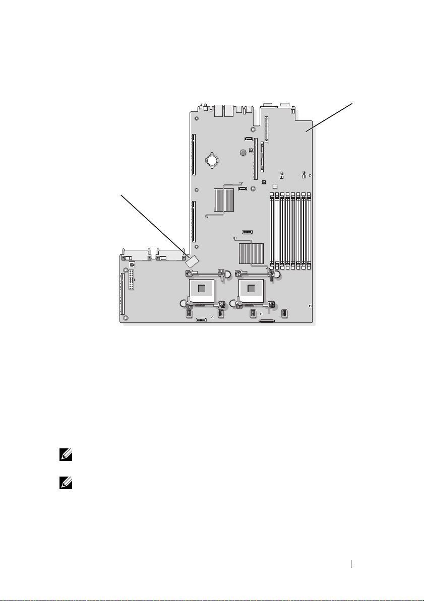
Figure 1-1. Internal USB Connector Location
2
1 system board 2 internal USB connector location
1
To boot from the USB memory key, you must configure the USB memory
key with a boot image and then specify the USB memory key in the boot
sequence in the System Setup program. See
Program" in the
Hardware Owner’s Manual
"Using the System Setup
. For information on creating
a bootable file on the USB memory key, see the user documentation that
accompanied the USB memory key.
NOTE: USB keys that contain multiple LUNs (Logical Unit Numbers) must be
formatted using the format utility provided by the key manufacturer.
NOTE: To avoid interference with components inside the system, the USB key must
conform to the following maximum dimensions: 11.68mm thick (0.46") x 24.89mm
width (0.98") x 66.8mm length (2.63").
Information Update 7
Page 8
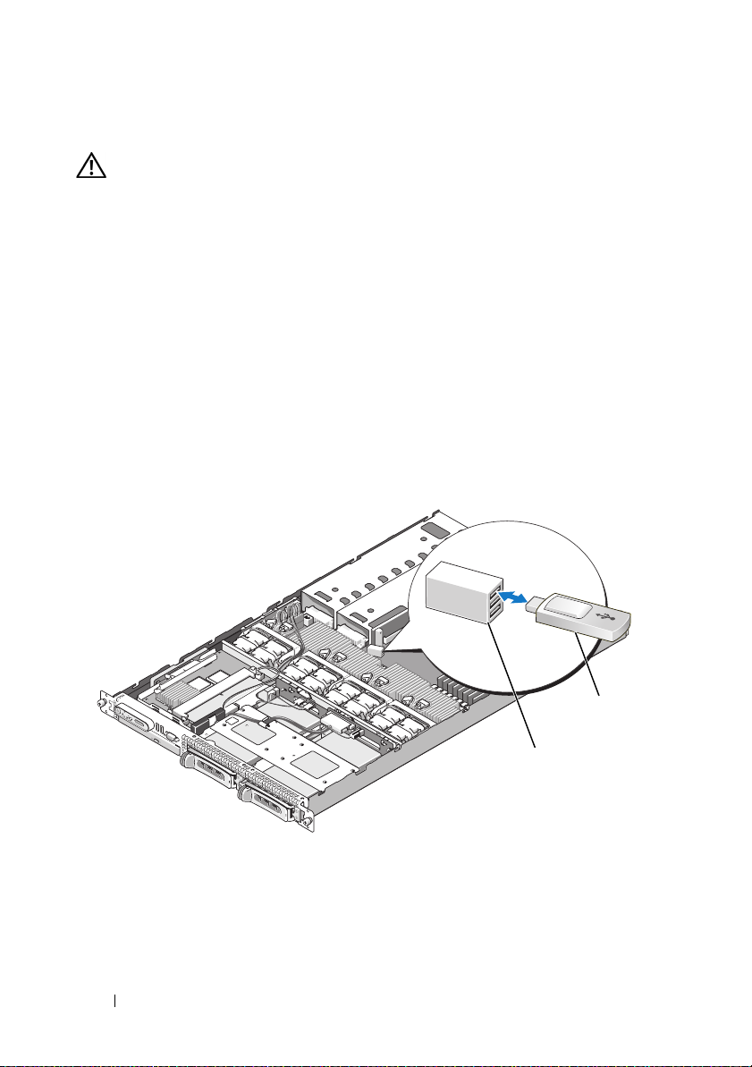
Installing the Optional Internal USB Memory Key
WARNING: Only trained service technicians are authorized to remove the system
cover and access any of the components inside the system. See your Product
Information Guide for complete information about safety precautions,
working inside the computer, and protecting against electrostatic discharge.
1
Turn off the system, including any attached peripherals, and disconnect
the system from its electrical outlet.
2
Open the system. See "Opening the System" in the
Manual
3
Remove the memory cooling shroud. See "Removing the Memory Cooling
Shroud" in the
4
Locate the USB connector on the system board and insert the USB
.
Hardware Owner’s Manual
.
memory key into the USB connector. See Figure 1-2.
Figure 1-2. Installing an Internal USB Key
Hardware Owner’s
1 USB memory key 2 internal USB connector
8 Information Update
1
2
Page 9

5
Replace the memory cooling shroud.
6
Close the system. See "Closing the System" in the
Manual
7
Reconnect the system to power and restart the system.
8
Enter the System Setup program and verify that the USB key has been
detected by the system. See "Using the System Setup Program" in the
Hardware Owner’s Manual
.
.
Hardware Owner’s
Support for 8-GB Memory Modules –
PowerEdge 1950 III Systems
PowerEdge 1950 III systems have added support for the following approved
8-GB memory configurations:
• 64 GB — 8 x 8-GB quad-rank memory modules
• 48 GB — 4 x 8-GB quad-rank and 4 x 4-GB dual-rank memory modules
If 64 GB of memory is installed, the system only recognizes and displays
63.75 GB during POST.
NOTE: Prior to upgrading your system, verify that the latest system BIOS version is on your
system. Loading the latest BIOS version ensures that your system is fully supported.
NOTE: Some operating systems cannot support more than 4 GB of physical memory. For
more information on memory support requirements and restrictions, refer to the operating
system documentation that ships with your system.
Processor Upgrades – PowerEdge 1950 II
and PowerEdge 1950 III Systems
• If the front of your system chassis is labeled with a "II," your system is
upgradeable to the 5100 series of dual-core Intel Xeon processors and
the 5300 series of quad-core Intel Xeon processors.
• If the front of your system chassis is labeled with a "III," your system is
upgradeable to the 5100 and 5200 series of dual-core Intel Xeon processors
and the 5300 and 5400 series of quad-core Intel Xeon processors.
See support.dell.com for information on the latest processor upgrade options
for your system.
Information Update 9
Page 10

System Board Replacement – Safeguarding
Encrypted Data
On PowerEdge 1950 III systems using Windows Server® 2008, you can use
encryption programs, such as the BitLocker utility, to secure the contents
of the hard drive.
If you are using the TPM with an encryption application, you are prompted
to create a recovery key during system setup. Be sure to store this recovery key.
If you replace the system board, you must supply the recovery key when you
restart your system before you can access the encrypted files on your hard
drive(s).
System Message Update
Table 1-1 lists new system messages for the PowerEdge 1950 III system and
the probable cause and corrective action when the message appears.
WARNING: Only trained service technicians are authorized to remove the system
cover and access any of the components inside the system. See your Product
Information Guide for complete information about safety precautions,
working inside the computer, and protecting against electrostatic discharge
10 Information Update
Page 11

Table 1-1. System Messages
Message Causes Corrective Actions
Alert! Node
Interleaving
disabled! Memory
configuration does
not support Node
Interleaving.
The memory configuration
does not support node
interleaving, or the
configuration has changed
(for example, a failed
DIMM) so that node
interleaving cannot be
supported. The system
runs but with reduced
functionality.
Ensure that the memory
modules are installed in a
configuration that supports
node interleaving. Check
other system messages for
additional information
for possible causes. For
memory configuration
information, see "General
Memory Module
Installation Guidelines"
in the Hardware Owner’s
Manual. If the problem
persists, see
"Troubleshooting System
Memory" in the Hardware
Owner’s Manual.
!!*** Error: Remote
Access Controller
initialization
failure *** RAC
virtual USB devices
may not be
Remote Access Controller
initialization failure.
Ensure that the Remote
Access Controller is
properly installed. See
"Installing a RAC Card"
in the Hardware Owner’s
Manual.
available...
Invalid PCIe card
found in the
Internal_Storage
slot!
The system halted because
an invalid PCIe expansion
card is installed in the
dedicated storage
Remove the PCIe
expansion card and install
the internal SAS controller
in the dedicated slot.
controller slot.
No boot device
available
Faulty or missing optical
drive subsystem, hard
drive, or hard-drive
subsystem, or no bootable
USB key installed.
Use a bootable USB key,
CD, or hard drive. See
"Using the System Setup
Program" in the Hardware
Owner’s Manual for
information on setting
the order of boot devices.
Information Update 11
Page 12

Table 1-1. System Messages (continued)
Message Causes Corrective Actions
PCI BIOS failed to
install
PCIe Degraded Link
Width Error:
Embedded device
Expected Link Width
is n
Actual Link Width
is n
PCIe Degraded Link
Width Error:
Integrated device
Expected Link Width
is n
Actual Link Width
is n
PCIe Degraded Link
Width Error: Slot n
Expected Link Width
is n
Actual Link Width
is n
PCIe Training
Error: Embedded
device
PCIe device BIOS (Option
ROM) checksum failure
detected during shadowing.
Cables to expansion card(s)
loose; faulty or improperly
installed expansion card(s).
Faulty system board or riser
board.
The specified PCIe device
is faulty or improperly
installed.
Faulty or improperly
installed PCIe card in
the specified slot.
Faulty system board
or riser board.
Reseat the expansion
card(s). Ensure that all
appropriate cables are
securely connected to the
expansion card(s). If the
problem persists, see
"Troubleshooting System
Expansion Cards" in the
Hardware Owner’s Manual.
See "Getting Help" in the
Hardware Owner’s Manual.
For a SAS controller
daughter card, reseat the
card in the dedicated PCIe
connector. See "Installing a
SAS Controller Daughter
Card" in the Hardware
Owner’s Manual. If the
problem persists, see
"Getting Help" in the
Hardware Owner’s Manual.
Reseat the PCIe card in the
specified slot number. See
"Expansion Cards" in the
Hardware Owner’s Manual.
If the problem persists,
see "Getting Help" in the
Hardware Owner’s Manual.
See "Getting Help" in the
Hardware Owner’s Manual.
12 Information Update
Page 13

Table 1-1. System Messages (continued)
Message Causes Corrective Actions
PCIe Training
Error: Integrated
device
PCIe Training
Error: Slot n
Remote Access
Controller cable
error or incorrect
card in the RAC
slot.
The specified PCIe device
is faulty or improperly
installed.
Faulty or improperly
installed PCIe card in the
specified slot.
RAC cables not connected,
or RAC card installed in
wrong expansion slot.
For a SAS controller
daughter card, reseat the
card in the dedicated PCIe
connector. See "Installing
a SAS Controller Daughter
Card" in the Hardware
Owner’s Manual. If the
problem persists, see
"Getting Help" in the
Hardware Owner’s Manual.
Reseat the PCIe card in the
specified slot number. See
"Expansion Cards" in the
Hardware Owner’s Manual.
If the problem persists, see
"Getting Help" in the
Hardware Owner’s Manual.
Check that the RAC cables
are connected, and that the
RAC card is installed in the
correct expansion slot. See
"Installing a RAC Card" in
the Hardware Owner’s
Manual.
NOTE: All TPM information messages appear after the BMC option ROM has been
loaded during POST.
TPM configuration
operation honored.
TPM Failure A Trusted Platform Module
System now resets. Information only.
See "Getting Help" in the
(TPM) function has failed.
Hardware Owner’s Manual.
Information Update 13
Page 14

Table 1-1. System Messages (continued)
Message Causes Corrective Actions
TPM operation is
pending. Press I to
Ignore or M to
Modify to allow
Configuration change has
been requested.
Press I to continue system
boot. Press M to modify
the TPM setting and
restart.
this change and
reset the system.
WARNING: Modifying
could prevent
security.
Warning: Following
faulty DIMMs are
disabled:
DIMM n
1 n2
Total memory size
Faulty or improperly seated
memory module(s).
DIMMs are disabled in
pairs, as indicated by the n
. Check both
and n
2
DIMMs for a possible fault.
See "Troubleshooting
System Memory" in the
Hardware Owner’s Manual.
1
is reduced.
Warning: A fatal
error has caused
system reset!
Please check the
system event log!
A fatal system error
occurred and caused the
system to restart.
Check the SEL for
information that was
logged during the error.
See the applicable
troubleshooting section in
See "Troubleshooting Your
System" in the Hardware
Owner’s Manual. for any
faulty components
specified in the SEL.
Warning! No micro
code update loaded
for processor n
Micro code update failed. Update the BIOS firmware.
See "Getting Help" in the
Hardware Owner’s Manual.
14 Information Update
Page 15

Table 1-1. System Messages (continued)
Message Causes Corrective Actions
Warning: The
installed memory
configuration is
not optimal. For
more information on
valid memory
configurations,
please see the
system
documentation on
the technical
support web site.
Write fault
Write fault on
selected drive
Invalid memory
configuration. The system
runs but with reduced
functionality.
Faulty USB device, USB
medium, optical drive
assembly, hard drive, or
hard-drive subsystem.
Ensure that the memory
modules are installed in a
valid configuration. See
"General Memory Module
Installation Guidelines"
in the Hardware Owner’s
Manual. If the problem
persists, see
"Troubleshooting System
Memory" in the Hardware
Owner’s Manual.
Replace the faulty media.
Reseat the USB device or
USB cable. For hard drive
problems, see
"Troubleshooting a Hard
Drive" in the Hardware
Owner’s Manual.
LCD Status Messages Update
Table 1-2 lists updates to the LCD status messages that can occur on
the PowerEdge 1950 III system and the probable cause for each message.
The LCD messages refer to events recorded in the system event log (SEL).
For information on the SEL and configuring system management settings,
see your systems management software documentation.
Information Update 15
Page 16

Table 1-2. LCD Status Messages
Code Text Causes Corrective Actions
N/A SYSTEM NAME A 62-character
string that can be
defined by the user
in the System Setup
program.
The SYSTEM NAME
is displayed under
the following
conditions:
• The system is
powered on.
• The power is off
and active errors
are displayed.
E1000 FAILSAFE, Call
Support
E1118 CPU Temp
Interface
E1211 ROMB Batt RAID battery is
Check the system
event log for critical
failure events.
The BMC is unable
to determine
the CPU(s)
temperature status.
Consequently, the
BMC increases
the CPU fan speed
to maximum
as a precautionary
measure.
either missing, bad,
or unable to
recharge due to
thermal issues.
This message is for
information only.
You can change the
system ID and
name in the System
Setup program. See
"Using the System
Setup Program" in
the Hardware
Owner’s Manual.
See "Getting Help"
in the Hardware
Owner’s Manual.
Turn off power to
the system and
restart the system.
If the problem
persists, see
"Getting Help"
in the Hardware
Owner’s Manual.
Reseat the RAID
battery connector.
See the "RAID
Battery" and see
"Troubleshooting
System Cooling
Problems" in the
Hardware Owner’s
Manual.
16 Information Update
Page 17

Table 1-2. LCD Status Messages (continued)
Code Text Causes Corrective Actions
E1625 PS AC Current Power source is out
of acceptable range.
E1711 PCI PERR B##
D## F##
PCI PERR Slot #The system BIOS
The system BIOS
has reported a PCI
parity error on a
component that
resides in PCI
configuration space
at bus ##, device
##, function ##.
has reported a PCI
parity error on a
component that
resides in the
specified PCIe slot.
Check the AC
power source.
Remove and reseat
the PCIe expansion
cards. If the
problem persists,
see
"Troubleshooting
an Expansion Card"
in the Hardware
Owner’s Manual.
Reinstall the
expansion-card riser.
See "Expansion
Card Risers" in the
Hardware Owner’s
Manual.
If the problem
persists, the riser
card or system board
is faulty. See
"Getting Help"
in the Hardware
Owner’s Manual.
Information Update 17
Page 18

Table 1-2. LCD Status Messages (continued)
Code Text Causes Corrective Actions
E1712 PCI SERR B##
D## F##
PCI SERR
Slot #
The system BIOS
has reported a PCI
system error on a
component that
resides in PCI
configuration space
at bus ##, device
##, function ##.
The system BIOS
has reported a PCI
system error on a
component that
resides in the
specified slot.
Remove and reseat
the PCIe expansion
cards. If the
problem persists,
see
"Troubleshooting
Expansion Cards"
in the Hardware
Owner’s Manual.
Reinstall the
expans ion-card ris er.
See "Expansion
Card Risers" in the
Hardware Owner’s
Manual.
If the problem
persists, the riser
card or system board
is faulty. See
"Getting Help"
in the Hardware
Owner’s Manual.
18 Information Update
Page 19

Table 1-2. LCD Status Messages (continued)
Code Text Causes Corrective Actions
E171F PCIE Fatal Err
B## D## F##
PCIE Fatal Err
Slot #
E1914 DRAC5 Conn2
Cbl
E1B01 USB#
Overcurrent
The system BIOS
has reported a PCIe
fatal error on a
component that
resides in PCIe
configuration space
at bus ##, device
##, function ##.
The system BIOS
has reported a PCIe
fatal error on a
component that
resides in the
specified slot.
DRAC 5 cable is
missing or
disconnected.
Device plugged in
the specified USB
port caused an
overcurrent
condition.
Remove and reseat
the PCIe expansion
cards. If the
problem persists,
see
"Troubleshooting
Expansion Cards"
in the Hardware
Owner’s Manual.
Reinstall the
expansion-card riser.
See "Expansion
Card Risers" in the
Hardware Owner’s
Manual.
If the problem
persists, the riser
card or system board
is faulty. See
"Getting Help"
in the Hardware
Owner’s Manual.
Reconnect the
cable. See
"Installing a RAC
Card" in the
Hardware Owner’s
Manual.
Reseat the device
cable. If the
problem persists,
replace or remove
the device.
Information Update 19
Page 20

Table 1-2. LCD Status Messages (continued)
Code Text Causes Corrective Actions
E2110 MBE DIMM # & # One of the two
indicated DIMMs
has had a memory
multi-bit error
(MBE).
E2111 SBE Log
Disable DIMM #
E2112 Mem Spare
DIMM #
I1915 Video Off
(LCD lights with
a blue or amber
background.)
I1916 Video Off
in ##
(LCD lights with
a blue or amber
background.)
The system BIOS
has disabled
memory single-bit
error (SBE) logging,
and does not
resume logging
further SBEs until
the system is
restarted. "#"
represents the
DIMM implicated
by the BIOS.
The system BIOS
has spared the
memory because it
has determined that
the memory had too
many errors. "# &
#" represents the
DIMM pair
implicated by
the BIOS.
The video has been
turned off by the
RAC remote user.
The video was
turned off in xx
seconds by the RAC
remote user.
See
"Troubleshooting
System Memory"
in the Hardware
Owner’s Manual.
See
"Troubleshooting
System Memory"
in the Hardware
Owner’s Manual.
See
"Troubleshooting
System Memory"
in the Hardware
Owner’s Manual.
Information only.
Information only.
20 Information Update
Page 21

System Setup Program Update
Memory Screen
Table 1-3 lists the descriptions for the information fields that appear on
the Memory Information screen.
Table 1-3. Memory Information Screen Options
Option Description
System Memory Size Displays the amount of system memory.
System Memory Type Displays the type of system memory.
System Memory Speed Displays the system memory speed.
Video Memory Displays the amount of video memory.
System Memory Testing Specifies whether system memory tests are run at system
boot. Options are Enabled and Disabled.
Redundant Memory
(Disabled default)
Node Interleaving
(Disabled default)
Low Power Mode
(Disabled default)
Enables or disables the redundant memory feature.
When set to Spare Mode, the first rank of memory on
each DIMM is reserved for memory sparing. Redundant
memory feature is disabled if the Node Interleaving field
is enabled.
If this field is set to Enabled, memory interleaving is
supported if a symmetric memory configuration is
installed. If this field is set to Disabled, the system can
support Non-Uniform Memory architecture (NUMA)
(asymmetric) memory configurations.
NOTE: The Node Interleaving field must be set to Disabled
when using the redundant memory feature.
Enables or disables the low power mode of the memory.
When set to Disabled, the memory runs at full speed.
When set to Enabled, the memory runs at a reduced
speed to conserve energy.
Information Update 21
Page 22

CPU Information Screen
Table 1-4 updates the description for the Demand-Based Power Management
option.
Table 1-4. CPU Information Screen
Option Description
Demand-Based Power
Management
(Enabled default)
NOTE: Check your operating system documentation to
verify if the operating system supports this feature.
Enables or disables demand-based power management.
When enabled, the CPU Performance State tables are
reported to the operating system; when disabled, the
CPU Performance State tables are not reported to the
operating system. If any of the CPUs do not support
demand-based power management, the field becomes
read-only, and is automatically set to Disabled.
Integrated Devices Screen
Table 1-5 lists new Integrated Devices screen options.
Table 1-5. Integrated Devices Screen Options
Option Description
Internal USB Port
(On default)
OS Watchdog
Timer
(Disabled default)
Enables or disables the system’s internal USB port.
NOTE: You can only enable the internal USB port if the User
Accessible USB Ports option on this screen is set to All ports
On (the default value).
NOTE: This feature is usable only with operating systems that
support WDAT implementations of the Advanced Configuration
and Power Interface (ACPI) 3.0b specification. Microsoft
Windows Server
Server 2003 does not.
Sets a timer that monitors the operating system for activity
and aids in recovery if the system stops responding. When
this field is set to Enabled, the operating system is allowed
to initialize the timer. When set to Disabled, the timer is
not initialized.
®
2008 supports this feature, but Windows
®
22 Information Update
Page 23

Table 1-5. Integrated Devices Screen Options (continued)
Option Description
I/OAT DMA
Engine
(Disabled default)
System Interrupts
Assignment
(Standard default)
Enables or disables the I/O Acceleration Technology (I/OAT)
option. When set to Enabled, I/OAT reduces system CPU
usage for applications that use TCP by offloading part of TCP
receive operation to the DMA engine.
This field controls the interrupt assignment for PCI devices
in the system. When set to Distributed, interrupt routing is
swizzled to minimize IRQ sharing among devices.
System Security Screen
Table 1-6 lists new options for the PowerEdge 1950 III system.
NOTE: Systems that are shipping in China are not equipped with TPM.
CAUTION: Before enabling the TPM Security option, ensure that the operating
system supports TPM.
Table 1-6. New System Security Screen Options
Option Description
TPM Security
(Off default)
Sets the reporting of the Trusted Platform Module
(TPM) in the system.
When set to Off (default), presence of the TPM is
not reported to the operating system.
When set to On with Pre-boot Measurements, the
system reports the TPM to the operating system and
stores the pre-boot measurements (compliant with
Trusted Computing Group standards) to the TPM during
POST.
When set to On without Pre-boot Measurements, the
system reports the TPM to the operating system and
bypasses pre-boot measurements.
Information Update 23
Page 24

Table 1-6. New System Security Screen Options (continued)
Option Description
TPM Activation Changes the operational state of the TPM.
When set to Activate, the TPM is enabled and activated
at default settings.
When set to Deactivate, the TPM is disabled and
deactivated.
The No Change state initiates no action. The operational
state of the TPM remains unchanged (all user settings for
the TPM are preserved).
NOTE: This field is read-only when TPM Security is set
to Off.
TPM Clear
(No default)
CAUTION: Clearing the TPM causes loss of all
encryption keys in the TPM. This prevents booting to
the operating system and results in loss of data if the
encryption keys cannot be restored. Be sure to back
up the TPM keys prior to enabling this option.
When set to Yes , all the contents of the TPM are cleared.
NOTE: This field is read-only when TPM Security is set
to Off.
Table 1-7 lists the updated information on the default Failsafe Baud Rate.
Table 1-7. Serial Communication Screen Option
Option Description
Failsafe Baud
Rate (115200
default)
Displays the failsafe baud rate used for console redirection when
the baud rate cannot be negotiated automatically with the remote
terminal. This rate should not be adjusted.
24 Information Update
Page 25

Operating System Information
Enumeration of NICs
Linux operating system versions that use the udev kernel device manager
enumerate the NICs differently than earlier Linux versions that used the
devfs device manager. Although this does not affect system functionality,
when using Red Hat
Linux Enterprise Server 9 or 10 operating systems, the NICs are enumerated
in reverse: NIC1 is configured as eth1 instead of eth0, and NIC2 is configured
as eth0 instead of eth1. For information on how to change the default device
enumerations, see the "Network Interface Card Naming" white paper
available at linux.dell.com.
RHEL – Incorrect Processor Information
• If an Intel Xeon 54xx processor is installed in a system running RHEL
Version 4 Update 5 and Demand-Based Switching is enabled in the BIOS,
cat/proc/cpuinfo
cat/sys/devices/system/cpu/cpuxx/cpufreq/scaling_
cur_freq
processor speed is not affected.)
• If an Intel Xeon 54
Version 3 Update 9, incorrect processor information is displayed in
/proc/cpuinfo
This behavior will be corrected in a future RHEL 4 Update.
®
Enterprise Linux® (version 4 or version 5) or SUSE®
and
displays an incorrect processor frequency. (The actual
xx
processor is installed in a system running RHEL
. (The actual processor speed is not affected.)
System Support for Microsoft Windows 2000
If you run the System Build and Update Utility, Microsoft® Windows® 2000
is included in the list of operating systems on the Server OS Install tab.
This operating system is supported by the PowerEdge 1950 and 1950 II
systems, but not by the PowerEdge 1950 III system.
Information Update 25
Page 26

Hardware Owner’s Manual Updates
Installing the Processor
When installing the processor, the processor shield must be closed before
securing the processor with the socket release lever.
System Diagnostics Custom Test Options
In the Customize window of the system diagnostics, the Log output file
pathname option e
where the test log file is saved. You cannot save the file to a hard drive.
nables you to specify the diskette drive or USB memory key
26 Information Update
Page 27

Dell™ PowerEdge™
1950 系统
信息更新
Page 28

注、小心和警告
注:“注”表示可以帮助您更好地使用计算机的重要信息。
小心:“小心”表示如果不遵循说明,就有可能损坏硬件或
导致数据丢失。
警告:
“警告”表示可能会造成财产损失、人身伤害甚至死亡。
____________________
本说明文件中的信息如有更改,恕不另行通知。
© 2006–2009 Dell Inc.
未经
Dell Inc.
本文中使用的商标:
Corporation
国和
的注册商标;
本说明文件中述及的其它商标和产品名称是指拥有相应商标和产品名称的公司或其制造的
产品。
2009 年 11
书面许可,严禁以任何形式复制这些材料。
的注册商标;
或其它国家/地区的商标或注册商标;
/
SUSE
对本公司的商标和产品名称之外的其它商标和产品名称不拥有任何专有权。
Dell Inc.
月
版权所有,翻印必究。
Dell、DELL
是 Novell Inc.
Rev. A09
徽标和
Microsoft、Windows
的注册商标。
PowerEdge
和
Red Hat 和
是 Dell Inc.
Windows Server
的商标;
是 Microsoft Corporation
Red Hat Enterprise Linux
Intel
和
Xeon
是 Red Hat, Inc.
是 Intel
在美
Page 29

目录
非优化的内存配置 . . . . . . . . . . . . . . . . . . .
PowerEdge 1950 III –
全新性能
全新系统功能
. . . . . . . . . . . . . . . . . . . . . . 31
全新高效电源设备和电源监测功能
全新 I/O 和存储功能
全新安全保护功能
可选的内部
USB
存储钥匙
. . . . . . . . . . . . . . . . 31
. . . . . . . . . . . . . . . . 32
安装可选的内部 USB 存储钥匙
支持
处理器升级
PowerEdge 1950 III
系统板更换
系统信息更新
LCD
内存模块
8 GB
– PowerEdge 1950 II 和
保护加密数据
–
. . . . . . . . . . . . . . . . . . . . . .
状态信息更新
– PowerEdge 1950 III
. . . . . . . . . . . . . . . .
系统
. . . . . . . . . . . . . . . . . . .
. . . . . . . . . .
. . . . . . . 31
. . . . . . . . . . . . . . .
. . . . . . . . . 33
系统
. . . .
. . . . . . . . . . . . . .
31
31
32
35
35
35
36
41
目录 29
Page 30

系统设置程序更新 . . . . . . . . . . . . . . . . . . .
内存屏幕
CPU Information (CPU 信息)屏幕
Integrated Devices (集成设备)屏幕
System Security (系统安全保护)屏幕
. . . . . . . . . . . . . . . . . . . . . . 45
. . . . . . . 46
. . . . . . 46
. . . . . 47
45
操作系统信息
枚举 NIC
. . . . . . . . . . . . . . . . . . . . . .
. . . . . . . . . . . . . . . . . . . . . . 49
RHEL – 错误的处理器信息
Microsoft Windows 2000 的系统支持
《硬件用户手册》更新
安装处理器
. . . . . . . . . . . . . . . . .
. . . . . . . . . . . . . . . . . . . . . 50
系统诊断程序自定义检测选项
49
. . . . . . . . . . . . 49
. . . . . . . 49
50
. . . . . . . . . . 50
30 目录
Page 31

非优化的内存配置
当系统检测到非优化的内存配置,
信息时:
Non-Optimal Memory Configuration
(非优化的内存配置)
Press F1 to continue or F2 for Setup
(按
继续,按
F1
注:混合使用不同速度的
低到通道的
DIMM
PowerEdge 1950 III –
进行设置)
F2
DIMM
集中最慢的速度。
全新系统功能
可能会中止,并显示以下
POST
会导致内存配置非优化。系统会将性能降
全新性能
•
两个双核或四核
•
内存模块支持。
8 GB
Intel® Xeon® 5400
系列和
系列处理器。
5300
全新高效电源设备和电源监测功能
•
在不同的工作负载之间进行功率转换,以使系统效率更高。
•
底板管理控制器
使用。
全新
•
•
•
•
和存储功能
I/O
可选
Intel
1000 Mbps
支持
10 Gb
一个内部
存储钥匙(可选)。
支持
SAS 6i/R 和 PERC 6/i
(BMC)
四端口千兆位以太网
数据速率以及
以太网卡。
USB 2.0
电源监测可监测电流、电压以及系统中的电源
,可支持
NIC
远程引导。
iSCSI
兼容连接器,支持可引导
适配器(可选)。
10 Mbps、100 Mbps 和
快擦写驱动器或
USB
USB
信息更新 31
Page 32

全新安全保护功能
•
受信任的平台模块
•
支持
引导(可选)。
iSCSI
(TPM)
,支持增强的安全保护级别。
可选的内部
PowerEdge 1950 III
合
设备、安全保护密钥或大容量存储设备。要使用内部
用系统设置程序的
Port
(集成设备)屏幕”。
图
快擦写存储钥匙使用 (请参阅图
USB
(内部
USB
内部
1-1.
USB
系统提供了一个位于系统板上的内部
Integrated Devices
端口)选项。请参阅第
连接器位置
USB
2
存储钥匙
1-1)。USB
(集成设备)屏幕中的
46
页上的 “
连接器,可配
USB
存储钥匙可用作引导
连接器,必须启
USB
Internal USB
Integrated Devices
1
32 信息更新
1
系统板
2
内部
USB
连接器位置
Page 33

要从
系统设置程序的引导顺序中指定
中的“使用系统设置程序”。有关在
信息,请参阅
存储钥匙引导,必须为
USB
存储钥匙随附的用户说明文件。
USB
注:必须使用钥匙制造商提供的格式化公用程序对包含多个
号码)的
钥匙进行格式化。
USB
存储钥匙配置一个引导映像,然后在
USB
存储钥匙。请参阅《硬件用户手册》
USB
存储钥匙上创建可引导文件的
USB
(逻辑单元
LUN
注:为了避免与系统内部的组件相冲突,
毫米厚(
11.68
(
英寸)。
2.63
安装可选的内部
1
2
3
警告:
只有经过培训的维修技术人员才能卸下系统护盖并拆装系统内部的
任何组件。有关安全预防措施、拆装计算机内部组件以及防止静电损害的完
整信息,请参阅 《产品信息指南》。
关闭系统和所有连接的外围设备,并断开系统与电源插座的连接。
打开系统护盖。请参阅《硬件用户手册》中的“打开系统护盖”。
卸下内存冷却导流罩。请参阅《硬件用户手册》中的“卸下内存冷却
0.46
USB
英寸)
存储钥匙
x 24.89
毫米宽(
钥匙不能超出以下规格上限:
USB
0.98
英寸)
x 66.8
毫米长
导流罩”。
4
找到系统板上的
接器。请参阅图
连接器,然后将
USB
。
1-2
存储钥匙插入
USB
USB
连
信息更新 33
Page 34

图
1-2.
安装内部
USB
钥匙
1
2
1
5
装回内存冷却导流罩。
6
合上系统护盖。请参阅《硬件用户手册》中的“合上系统护盖”。
7
将系统重新连接至电源,然后重新启动系统。
8
进入系统设置程序,并验证系统是否检测到
USB
存储钥匙
2
内部
USB
USB
连接器
钥匙。请参阅
《硬件用户手册》中的“使用系统设置程序”。
34 信息更新
Page 35

支持
PowerEdge 1950 III
如果安装了
8 GB
•
64 GB
•
48 GB
注:
在升级系统之前,请验证系统上的系统
版本可以确保系统得到全面支持。
注:
某些操作系统无法支持超过
请参阅系统附带的操作系统说明文件。
内存模块
系统添加了对以下经过许可的
—
8 x 8 GB
—
4 x 8 GB
64 GB
的内存,则在
四排内存模块
四排和
– PowerEdge 1950 III
内存配置的支持:
8 GB
4 x 4 GB
POST
4 GB
双排内存模块
期间,系统仅识别并显示
是否为最新版本。载入最新的
BIOS
的物理内存。有关内存支持要求和限制的详情,
系统
63.75 GB
BIOS
。
处理器升级
PowerEdge 1950 III
•
如果系统机箱前面有“II”标记,则表明您的系统可升级到具有双
核
Intel Xeon
系列。
5300
•
如果系统机箱前面有“
Intel Xeon
的
5300 和 5400
有关系统最新处理器升级选项的信息,请参阅
系统板更换
在使用
Windows Server® 2008 的 PowerEdge 1950 III
密程序(如
如果您将
创建一个恢复密钥。请确保好好存储此恢复密钥。如果更换系统板,您必须
在重新启动系统时提供恢复密钥,才能访问硬盘驱动器上的加密文件。
BitLocker
TPM
– PowerEdge 1950 II 和
系统
处理器的
处理器的
与加密应用程序配合使用,系统会提示您在系统设置过程中
5100 和 5200
系列。
保护加密数据
–
公用程序)保护硬盘驱动器上内容的安全。
系列和具有四核
5100
”标记,则表明您的系统可升级到具有双核
III
系列以及具有四核
Intel Xeon
support.dell.com
系统上,您可以使用加
处理器的
Intel Xeon
。
处理器
信息更新 35
Page 36

系统信息更新
表
1-1 列出 PowerEdge 1950 III
系统新的系统信息、出现这些信息的可能原
因以及纠正措施。
警告:
表
1-1.
信息 原因 纠正措施
Alert!Node
Interleaving
disabled! Memory
configuration does
not support Node
Interleaving.
(警报!节点交叉存取已
禁用!内存配置不支持节
点交叉存取。)
!!*** Error: Remote
Access Controller
initialization
failure *** RAC
virtual USB devices
may not be
available...
(
!!***
问控制器初始化失败
RAC 虚拟 USB
不可用
Invalid PCIe card
found in the
Internal_Storage
slot!
(在
Internal_Storage
插槽中找到无效的
PCIe
只有经过培训的维修技术人员才能卸下系统护盖并拆装系统的任何
内部组件。有关安全预防措施、拆装计算机内部组件以及防止静电释放的完
整信息,请参阅 《产品信息指南》。
系统信息
错误:远程访
)
...
卡!)
***
设备可能
内存配置不支持节点交叉
存取,或配置已更改
(例如,
导致无法支持节点交叉
系统会继续运行,
存取。
但功能有所降低。
远程访问控制器初始化
失败。
由于在专用存储控制器插
槽中安装了无效的
充卡,因此系统停机。
DIMM
出现故障)
PCIe
请确保将内存模块安装在
支持节点交叉存取的配
置中。请查看其它系统
信息,以获取有关可能原
因的更多信息。有关内存
配置的信息,请参阅《硬
件用户手册》中的“一般
内存模块安装原则”。
如果问题仍然存在,请参
阅《硬件用户手册》中的
“系统内存故障排除”。
确保远程访问控制器已
正确安装。请参阅《硬件
用户手册》中的“安装
卡”。
RAC
卸下
扩
用插槽中安装内部
制器。
扩充卡,在专
PCIe
SAS
控
36 信息更新
Page 37

表
系统信息 (续)
1-1.
信息 原因 纠正措施
No boot device
available
(无可用的引
导设备)
光盘驱动器子系统、硬盘
驱动器或硬盘驱动器子系
统出现故障或丢失,或没
有安装可引导
USB
钥匙。
请使用可引导
或硬盘驱动器。有关
CD
设置引导设备顺序的信
息,请参阅《硬件用户
手册》中的“使用系统设
置程序”。
PCI BIOS failed to
install
PCI BIOS
(无法安装
)
在
shadowing
期间检测到
(选项
BIOS
和故障。
扩充卡的电缆松动;
扩充卡出现故障或未正确
效率增强
PCIe 设备
)校验
ROM
请重置扩充卡。请确保所
有相应电缆都已稳固地连
接至扩充卡。如果问题仍
然存在,请参阅《硬件用
户手册》中的“系统扩充
卡故障排除”。
安装。
PCIe Degraded Link
Width Error:
系统板或提升板出现
故障。
请参阅《硬件用户手册》
中的“获得帮助”。
Embedded device
(
PCIe
降级链路宽度错
误:嵌入式设备)
Expected Link Width
is n
(预期的链路宽度为 n)
Actual Link Width
is n
(实际链路宽度为 n)
PCIe Degraded Link
Width Error:
Integrated device
(
PCIe
降级链路宽度错
误:集成设备)
Expected Link Width
is n
(预期的链路宽度为 n)
指定
设备出现故障或
PCIe
安装不正确。
对于
SAS
在专用
该卡。请参阅《硬件用户
手册》中的“安装
控制器子卡”。如果问题
仍然存在,请参阅《硬件
用户手册》中的“获得
帮助”。
Actual Link Width
is n
(实际链路宽度为 n)
USB
控制器子卡,请
连接器中重置
PCIe
钥匙、
SAS
信息更新 37
Page 38

表
信息 原因 纠正措施
PCIe Degraded Link
Width Error: Slot n
(
误:插槽 n)
Expected Link Width
is n
(预期的链路宽度为 n)
Actual Link Width
is n
(实际链路宽度为 n)
PCIe Training
Error: Embedded
device(PCIe
误:嵌入式设备)
PCIe Training
Error: Integrated
device(PCIe
误:集成设备)
PCIe Training
Error: Slot n
(
插槽 n)
Remote Access
Controller cable
error or incorrect
card in the RAC
slot.(远程访问控制器
电缆错误或
安装的卡不正确。)
注:所有
系统信息 (续)
1-1.
降级链路宽度错
PCIe
对准错误:
PCIe
TPM
RAC
信息均在
对准错
对准错
插槽中
指定插槽中的
故障或未正确安装。
系统板或提升板出现
故障。
指定
安装不正确。
指定插槽中的
故障或未正确安装。
RAC
或
RAC
充槽中。
POST
设备出现故障或
PCIe
电缆未连接,
卡安装在错误的扩
期间载入
BMC 选项 ROM
PCIe
PCIe
卡出现
卡出现
请在指定编号的插槽中
重置
PCIe
《硬件用户手册》中的
“扩充卡”。如果问题
仍然存在,请参阅
《硬件用户手册》中的
“获得帮助”。
请参阅《硬件用户手册》
中的“获得帮助”。
对于
SAS
请在专用
置该卡。请参阅《硬件用
户手册》中的“安装
控制器子卡”。如果问
题仍然存在,请参阅
《硬件用户手册》中的
“获得帮助”。
请在指定编号的插槽中重
置
PCIe
《硬件用户手册》中的
“扩充卡”。如果问题仍然
存在,请参阅 《硬件用户
手册》中的 “获得帮助”。
检查
RAC
接,
RAC
确的扩充槽中。请参阅
《硬件用户手册》中的
“安装
后才能显示。
卡。请参阅
控制器子卡,
连接器中重
PCIe
卡。请参阅
电缆是否已连
卡是否安装在正
卡”。
RAC
SAS
38 信息更新
Page 39

表
系统信息 (续)
1-1.
信息 原因 纠正措施
TPM configuration
系统会立即重设。 仅供参考。
operation honored.
(
TPM
配置操作已
执行。)
TPM Failure
(
故障)
TPM
TPM operation is
pending.Press I to
Ignore or M to
受信任的平台模块
(TPM)
功能出现故障。
请求更改配置。 按
请参阅《硬件用户手册》
中的“获得帮助”。
继续系统引导。
I
按
M 修改 TPM
新启动。
Modify to allow
this change and
reset the
system.WARNING:
Modifying could
prevent security.
(
忽略,或按
操作挂起。按
TPM
M
I
修改,
以允许进行此更改并重设
系统。警告:修改可能会
影响安全性。)
Warning: Following
faulty DIMMs are
disabled:
(警告:以下出现故障的
被禁用:)
DIMM
DIMM
n
1 n2
内存模块出现故障或未
正确就位。
禁用,以
分别检查两个
DIMM
n1 和
n2
DIMM
出可能的故障。
成对
表示。
请参阅《硬件用户手册》
中的“系统内存故障
排除”。
,找
Total memory size
is reduced.
(总内存大小减小。)
Warning: A fatal
error has caused
system reset!Please
check the system
event log!
(警告:
致命错误导致系统重设!
请检查系统事件日志!)
出现严重系统错误,导致
系统重新启动。
请查看
过程中记录的信息。有关
中指定的任何出现故
SEL
障的组件,请参阅《硬件
用户手册》的“系统故障
排除”中相应的故障排除
部分。
以获取在出错
SEL
设置并重
信息更新 39
Page 40

表
信息 原因 纠正措施
Warning! No micro
code update loaded
for processor n
(警告!未载入处理器
的微代码更新)
Warning: The
installed memory
configuration is
not optimal. For
more information on
valid memory
configurations,
please see the
system
documentation on
the technical
support web site.
(警告:当前安装的不是
最佳的内存配置。有关有
效的内存配置的详情,请
参阅技术支持网站上的系
统说明文件。)
Write fault
(写入故障)
Write fault on
selected drive
驱动器出现写入故障)
系统信息 (续)
1-1.
n
(选定
微代码更新失败。 请更新
《硬件用户手册》中的
“获得帮助”。
内存配置无效。系统会
继续运行,但功能有所
降低。
设备、
USB
盘驱动器部件、硬盘驱动
器或硬盘驱动器子系统出
现故障。
USB
介质、光
请确保内存模块安装在有
效的配置中。请参阅《硬
件用户手册》中的“一般
内存模块安装原则”。
如果问题仍然存在,请参
阅《硬件用户手册》中的
“系统内存故障排除”。
更换出现故障的介质。
重置
USB
电缆。有关硬盘驱动器的
问题,请参阅《硬件用户
手册》中的“硬盘驱动器
故障排除”。
BIOS
设备或
固件。请参阅
USB
40 信息更新
Page 41

状态信息更新
LCD
表
列出可能出现在
1-2
PowerEdge 1950 III
以及每条信息的可能原因。
事件。有关
和配置系统管理设置的信息,请参阅系统管理软件说明
SEL
文件。
系统中的
信息引用系统事件日志
LCD
状态信息的更新,
LCD
(SEL)
中记录的
表
1-2. LCD
代码 文本 原因 纠正措施
无
E1000 FAILSAFE, Call
E1118 CPU Temp
E1211 ROMB Batt
E1625 PS AC Current
状态信息
SYSTEM NAME
Support
Interface
由
个字符组成的
62
字符串,可由用户
在系统设置程序中
定义。
出现以下情况时会
SYSTEM
显示
:
NAME
•
打开系统电源。
•
关闭系统电源并
显示活动错误。
查看系统事件日志
以了解严重故障
事件。
无法确
BMC
定
因此,作为预防措
施,
风扇的速度增加到
最大。
RAID
坏或因温度问题而
无法再充电。
电源超出可接受
范围。
温度状态。
CPU
BMC 将CPU
电池丢失、损
此信息仅供参考。
您可以在系统设置
程序中更改系统
和名称。请参阅
《硬件用户手册》
中的“使用系统设
置程序”。
请参阅《硬件用户
手册》中的“获得
帮助”。
关闭系统电源并重
新启动系统。如果
问题仍然存在,请
参阅《硬件用户手
册》中的“获得
帮助”。
重置
RAID
接器。请参阅《硬
件用户手册》中的
“
RAID
“系统冷却问题故
障排除”。
检查交流电源。
ID
电池连
电池”和
信息更新 41
Page 42

表
1-2. LCD
代码 文本 原因 纠正措施
E1711 PCI PERR B##
E1712 PCI SERR B##
状态信息 (续)
D## F##
PCI PERR
Slot #
D## F##
PCI SERR
Slot #
系统
组件发生
校验错误,该组件
位于总线
##
配置空间。
系统
组件发生
校验错误,该组件
位于指定的
插槽。
系统
组件发生
错误,该组件位于
总线
功能
置空间。
系统
组件发生
错误,该组件位于
指定的插槽。
已报告
BIOS
奇偶
PCI
## 设备
功能
## 的 PCI
已报告
BIOS
奇偶
PCI
PCI
已报告
BIOS
系统
PCI
## 设备 ##
## 的 PCI
已报告
BIOS
系统
PCI
配
请卸下并重置
扩充卡。如果问题
仍然存在,请参阅
《硬件用户手册》
中的“扩充卡故障
排除”。
请重新安装扩充卡
提升板。请参阅
《硬件用户手册》
中的“扩充卡提
升板”。
如果问题仍然
存在,则表示提升
卡或系统板出现
故障。请参阅《硬件
用户手册》中的
“获得帮助”。
请卸下并重置
扩充卡。如果问题
仍然存在,请参阅
《硬件用户手册》
中的“扩充卡故障
排除”。
请重新安装扩充卡
提升板。请参阅
《硬件用户手册》
中的“扩充卡提
升板”。
如果问题仍然
存在,则表示提
升卡或系统板出现
故障。请参阅
《硬件用户手册》
中的 “获得
帮助”。
PCIe
PCIe
42 信息更新
Page 43

表
1-2. LCD
状态信息 (续)
代码 文本 原因 纠正措施
E171F PCIE Fatal Err
B## D## F##
PCIE Fatal Err
Slot #
系统
组件发生
BIOS
PCIe
已报告
错误,该组件位于
总线
##
PCIe
系统
组件发生
、设备
##
、功能
## 的
配置空间。
已报告
BIOS
PCIe
错误,该组件位于
指定的插槽。
请卸下并重置
致命
扩充卡。如果问题
仍然存在,请参阅
《硬件用户手册》
中的“扩充卡故障
排除”。
请重新安装扩充卡
致命
提升板。请参阅
《硬件用户手册》
中的“扩充卡提
升板”。
如果问题仍然存
在,则表示提升
卡或系统板出现
故障。请参阅
《硬件用户手册》
中的“获得
帮助”。
E1914 DRAC5 Conn2
Cbl
DRAC 5
或断开连接。
电缆丢失
重新连接电缆。
请参阅《硬件用户
手册》中的“安装
卡”。
RAC
E1B01 USB#
Overcurrent
插入指定
USB
端口
的设备导致出现过
流条件。
重置设备电缆。
如果问题仍然
存在,请更换或卸
下设备。
E2110 MBE DIMM # & #
两个指定
DIMM
的一个出现内存多
位错误
(MBE)
请参阅《硬件用户
中
手册》中的“系统
。
内存故障排除”。
PCIe
信息更新 43
Page 44

表
1-2. LCD
代码 文本 原因 纠正措施
E2111 SBE Log
E2112 Mem Spare
I1915 Video Off
I1916 Video Off in
状态信息 (续)
Disable DIMM #
DIMM #
(
LCD
有蓝色或琥珀色
背景。)
##
(
LCD
有蓝色或琥珀色
背景。)
亮起时具
亮起时具
系统
内存单位错误
(SBE)
新启动系统之前,
不会再记录更多的
SBE
BIOS
DIMM
系统
内存中有太多错
误,因此已将内存
释放。“
表示
DIMM
视频已被
用户关闭。
视频被
用户在
关闭。
已禁用
BIOS
记录,在重
。“#”表示
指示的
。
已确定
BIOS
# & #
指示的
BIOS
对。
远程
RAC
远程
RAC
秒钟内
xx
”
请参阅《硬件用户
手册》中的“系统
内存故障排除”。
请参阅《硬件用户
手册》中的“系统
内存故障排除”。
仅供参考。
仅供参考。
44 信息更新
Page 45

系统设置程序更新
内存屏幕
表
列出了
1-3
说明。
Memory Information
(内存信息)屏幕上显示的信息字段的
表
1-3. Memory Information
选项 说明
System Memory Size
(系统内存大小)
System Memory Type
(系统内存类型)
System Memory Speed
(系统内存速度)
Video Memory
(视频内存)
System Memory Testing
(系统内存检测)
Redundant Memory
(冗余内存)
(默认设置为
已禁用])
[
Node Interleaving
(节点交叉存取)
(默认设置为
已禁用])
[
Disabled
Disabled
(内存信息)屏幕选项
显示系统内存容量。
显示系统内存类型。
显示系统内存速度。
显示视频内存容量。
指定是否在系统引导时运行系统内存检测。选项为
Enabled
启用或禁用冗余内存功能。设置为
模式)时,每个
备用内存。如果已启用
存取)字段,则将禁用冗余内存功能。
当此字段设置为
称内存配置,则支持内存交叉存取。如果此字段设置为
Disabled
体系结构
注:使用冗余内存功能时,必须将
(节点交叉存取)字段设置为
Low Power Mode
(低功率模式)
(默认设置为
已禁用])
[
Disabled
启用或禁用内存的低功率模式。设置为
(已禁用)时,内存以全速运行。设置为
(已启用)时,内存以较低的速度运行,从而实现
节能。
(已启用)和
(已禁用),则系统可支持非一致性存取内存
(NUMA)
Disabled
DIMM
Node Interleaving
Enabled
(非对称)内存配置。
(已禁用)。
Spare Mode
中的第一列内存将保留用于
(已启用)时,如果安装了对
Node Interleaving
Disabled
(备用
(节点交叉
(已禁用)。
Disabled
Enabled
信息更新 45
Page 46

CPU Information(CPU
表
更新针对
1-4
选项的说明。
Demand-Based Power Management
信息)屏幕
(基于需求的电源管理)
表
1-4. CPU Information(CPU
选项 说明
Demand-Based Power
Management
电源管理)
(默认设置为
已启用])
[
(基于需求的
Enabled
Integrated Devices
表
列出新的
1-5
表
1-5. Integrated Devices
选项 说明
Internal USB Port
(内部
USB
(默认设置为
开])
[
OS Watchdog Timer
(
监视器计时器)
OS
(默认设置为
Disabled [
Integrated Devices
端口)
On
已禁用])
注:请查看您的操作系统说明文件,验证操作系统是
否支持此功能。
启用或禁用基于需求的电源管理。启用时,会向操作系
统报告
告
电源管理,该字段会变为只读字段,并自动设置为
Disabled
(集成设备)屏幕
(集成设备)屏幕选项
启用或禁用系统的内部
注:如果此屏幕上的
问的
USB
(默认值),则您仅可以启用内部
注:只有支持高级配置和电源接口
实现的操作系统才能使用此功能。
WDAT
Windows Server
不支持。
设置一个计时器,用于监测操作系统的活动,并在系统停
止响应时帮助系统恢复。如果此字段设置为
(已启用),操作系统可以初始化计时器。如果设置为
Disabled
信息)屏幕
性能状态表;禁用时,则不向操作系统报
CPU
性能状态表。如果任何
CPU
(已禁用)。
CPU
(集成设备)屏幕选项。
端口。
USB
User Accessible USB Ports
端口)选项设置为
®
2008
(已禁用),则不可初始化计时器。
All ports On
支持此功能,而
(启用所有端口)
端口。
USB
(ACPI) 3.0b
Microsoft
Windows Server 2003
不支持基于需求的
(用户可访
规格的
®
Enabled
46 信息更新
Page 47

表
1-5. Integrated Devices
选项 说明
I/OAT DMA Engine
(
I/OAT DMA
(默认设置为
Disabled [
System Interrupts
Assignment
(系统中断分配)
(默认设置为
Standard [
已禁用])
标准])
启用或禁用
引擎)
术
使用
负到
此字段控制系统中
Distributed
间的
(集成设备)屏幕选项 (续)
I/O Acceleration Technology (I/OAT)(I/O
[I/OAT]
)选项。如果设置为
的应用程序,
TCP
引擎,以减少系统
DMA
(分布式),中断路由会进行重排以最小化设备
共享。
IRQ
I/OAT
设备的中断分配。如果设置为
PCI
Enabled
通过将部分
的使用。
CPU
加速技
(已启用),对于
接收操作减
TCP
System Security
表
列出针对
1-6
注:
在中国发货的系统未附带
小心:启用
支持
TPM
表
选项 说明
TPM Security(TPM
保护)
(默认设置为
1-6.
新的
(系统安全保护)屏幕
PowerEdge 1950 III
TPM Security(TPM
。
System Security
Off [关]
(系统安全保护)屏幕选项
设置系统中受信任的平台模块
安全
如果设置为
)
告
设置为
引导测试)时,系统将在
告
标准)存储至
设置为
预引导测试)时,系统将向操作系统报告
且不经过预引导测试。
系统的全新选项。
。
TPM
安全保护)选项之前,请确保操作系统
(TPM)
(关闭)(默认),将不向操作系统报
Off
是否存在。
TPM
On with Pre-boot Measurements
期间向操作系统报
POST
并将预引导测试数据(符合受信任的计算组
TPM
。
TPM
On without Pre-boot Measurements
的报告。
(开,进行预
(开,不进行
,
TPM
信息更新 47
Page 48

表
选项 说明
1-6.
新的
System Security
(系统安全保护)屏幕选项 (续)
TPM Activation
(
激活)
TPM
TPM Clear(TPM
(默认设置为
表
列出有关默认
1-7
表
1-7. Serial Communication
选项 说明
Failsafe Baud Rate
(故障保护波特率)
(默认设置为
)
115200
清除)
No [否]
)
Failsafe Baud Rate
无法自动与远程终端协商波特率时,显示用于控制台重定向
的故障保护波特率。此速率不可调整。
更改
设置为
激活
设置为
活
TPM
No Change
作状态保持不变(
注:
时,该字段为只读。
设置为
注:
时,该字段为只读。
的操作状态。
TPM
Activate
TPM
Deactivate
TPM Security(TPM
小心:清除
丢失。如果无法恢复加密密钥,此选项会导致无
法引导到操作系统并导致数据丢失。在启用此选
项之前,请确保备份
Ye s
TPM Security(TPM
(激活)时,在默认设置下启用并
。
(取消激活)时,禁用并取消激
。
(无更改)状态不启动任何操作。
的所有用户设置将会保留)。
TPM
安全保护)设置为
TPM
(是)时,
会导致
TPM
的所有内容都将清除。
TPM
安全保护)设置为
中的所有加密密钥
TPM
密钥。
(故障保护波特率)的更新信息。
(串行通信)屏幕选项
TPM
Off
Off
的操
(关)
(关)
48 信息更新
Page 49

操作系统信息
枚举
NIC
与使用
的
Linux
但使用
Enterprise Server 9
配置为
更改默认设备枚举的信息,请参阅位于
Interface Card Naming
设备管理器的早期
devfs
操作系统版本枚举
Red Hat® Enterprise Linux
或
10
,而不是
eth1
eth0;NIC2
(网络接口卡命名)白皮书。
Linux
NIC
操作系统时,枚举
的方式不同。尽管这不会影响系统功能,
®
(版本
被配置为
版本相比,使用
或版本 5)或
4
的方式完全相反:
NIC
,而不是
eth0
linux.dell.com
内核设备管理器
udev
SUSE® Linux
eth1
上的
Network
被
NIC1
。有关如何
RHEL –
在将来的
Microsoft Windows 2000
如果运行
Microsoft® Windows
安装)选项卡上的操作系统列表中。
此操作系统,但
错误的处理器信息
•
如果在运行
理器,并在
cat/sys/devices/system/cpu/cpuxx/cpufreq/scaling_
cur_freq
如果在运行
•
理器,会在
际处理器速度。)
RHEL 4
RHEL
BIOS
RHEL
版本
4 更新 5
中启用按需切换,
均显示为错误的处理频率。(不影响实际处理器速度。)
版本
3 更新 9
/proc/cpuinfo 中显示错误的处理器信息。(不影响实
更新中,此问题会得到解决。
的系统中安装
cat/proc/cpuinfo 和
的系统中安装
Intel Xeon 54xx
Intel Xeon 54xx
的系统支持
System Build and Update Utility
®
将位于
2000
PowerEdge 1950 III
(系统构建和更新公用程序),
Server OS Install
PowerEdge 1950 和 1950 II
系统不支持此操作系统。
(服务器操作系统
处
处
系统支持
信息更新 49
Page 50

《硬件用户手册》更新
安装处理器
安装处理器时,在使用插槽释放拉杆固定处理器之前,必须合上处理器
护盖。
系统诊断程序自定义检测选项
在系统诊断程序的
(日志输出文件路径名)选项允许您指定用于保存检测日志文件的软盘驱动
器或
存储钥匙。您不能将文件保存在硬盘驱动器上。
USB
Customize
(自定义)窗口中,
Log output file pathname
50 信息更新
Page 51

Systèmes Dell™
PowerEdge™ 1950
Mise à jour
des informations
Page 52

Remarques, précautions et avertissements
REMARQUE : Une REMARQUE indique des informations importantes qui peuvent
vous aider à mieux utiliser votre ordinateur.
PRÉCAUTION : Une PRÉCAUTION vous avertit d'un risque de dommage matériel
ou de perte de données en cas de non-respect des instructions données.
AVERTISSEMENT: Un AVERTISSEMENT vous avertit d'un risque d'endom-
magement du matériel, de blessure corporelle ou de mort.
____________________
Les informations contenues dans ce document sont sujettes à modification sans préavis.
© 2006-2009 Dell Inc. Tous droits réservés.
La reproduction de ce document de quelque manière que ce soit sans l'autorisation écrite de Dell Inc.
est strictement interdite.
Marques mentionnées dans ce document :
Dell Inc. ;
Windows Server
ou dans d'autres pays ;
SUSE
D'autres marques commerciales et noms de marque peuvent être utilisés dans ce document pour faire
référence aux entités se réclamant de ces marques et de ces noms ou de leurs produits. Dell Inc. dénie
tout intérêt propriétaire vis-à-vis des marques commerciales et des noms de marque autres que les siens.
Novembre 2009 Rév. A09
Intel
et
Xeon
sont des marques déposées de Intel Corporation ;
sont des marques ou des marques déposées de Microsoft Corporation aux États-Unis et/
Red Hat
est une marque déposée de Novell Inc.
et
Dell
, le logo
DELL
Red Hat Enterprise Linux
et
PowerEdge
sont des marques déposées de Red Hat, Inc. ;
sont des marques de
Microsoft, Windows
et
Page 53

Table des matières
Configurations de mémoire non optimales . . . . . . . 55
Nouvelles fonctionnalités des systèmes
PowerEdge 1950 III
Nouvelles fonctions d'optimisation
des performances
Nouvelles fonctionnalités haute efficacité
pour l'alimentation et le contrôle
de l'alimentation
Nouvelles fonctions d'E/S et de stockage
Nouvelles fonctions de sécurité
. . . . . . . . . . . . . . . . . . . . 55
. . . . . . . . . . . . . . . . . 55
. . . . . . . . . . . . . . . . . . 55
. . . . . 56
. . . . . . . . . . 56
Clé de mémoire USB interne (en option)
. . . . . . . . 56
Installation de la clé de mémoire USB interne
en option
. . . . . . . . . . . . . . . . . . . . . . 58
Prise en charge de barrettes de mémoire 8 Go Systèmes PowerEdge 1950 III
. . . . . . . . . . . . . . 59
Mises à niveau du processeur pour les systèmes
PowerEdge 1950 II et III
. . . . . . . . . . . . . . . . . 60
Remplacement de la carte système Sauvegarde des données cryptées
Mise à jour des messages système
. . . . . . . . . . . 60
. . . . . . . . . . . 61
Mise à jour concernant les messages d'état
affichés sur l'écran LCD
. . . . . . . . . . . . . . . . . 67
Table des matières 53
Page 54

Mise à jour du programme de configuration
du système
. . . . . . . . . . . . . . . . . . . . . . . . 73
Écran relatif à la mémoire
. . . . . . . . . . . . . 73
Écran CPU Information
(Informations sur le processeur)
. . . . . . . . . . 75
Écran Integrated Devices
(Périphériques intégrés)
. . . . . . . . . . . . . . 75
Écran System Security
(Sécurité du système)
. . . . . . . . . . . . . . . . 77
Informations concernant le système d'exploitation. . . 79
Énumération des NIC
. . . . . . . . . . . . . . . . 79
Informations relatives au processeur
incorrectes sous RHEL
. . . . . . . . . . . . . . . 79
Support système pour Microsoft
Windows 2000
. . . . . . . . . . . . . . . . . . . . 80
Mises à jour du document Manuel du propriétaire . . . 80
Installation du processeur
. . . . . . . . . . . . . 80
Options disponibles dans les tests
personnalisés des diagnostics du système
. . . . . 80
54 Table des matières
Page 55

Configurations de mémoire non optimales
Lorsqu'une configuration de mémoire non optimale est détectée, le système
peut interrompre le POST et afficher le message suivant :
Non-Optimal Memory Configuration
(Configuration de mémoire non optimale)
Press F1 to continue or F2 for Setup
(Appuyez sur F1 pour poursuivre ou sur F2 pour accéder au menu
de configuration)
REMARQUE : l'utilisation de barrettes DIMM de cadences différentes rend la
configuration de la mémoire non optimale. Le système réduit la cadence système
à celle du jeu de barrettes DIMM la plus basse pour le canal.
Nouvelles fonctionnalités des systèmes PowerEdge 1950 III
Nouvelles fonctions d'optimisation des performances
• Deux processeurs double coeur ou quadruple coeur Intel® Xeon®
séries 5400 et 5300
• Prise en charge de barrettes de mémoire 8 Go
Nouvelles fonctionnalités haute efficacité pour l'alimentation et le contrôle de l'alimentation
• Efficacité renforcée de la gestion énergétique selon la charge de travail
• Contrôleur de gestion d'alimentation BMC (Baseboard Management
Controller) permettant de contrôler le courant, la tension et la puissance
utilisés par le système.
Mise à jour des informations 55
Page 56

Nouvelles fonctions d'E/S et de stockage
• Carte NIC Ethernet Gigabit Intel en option (quatre ports) prenant en
charge des débits de 10, 100 et 1000 Mbps, ainsi que l'amorçage iSCSI
à distance
• Prise en charge des cartes Ethernet 10 Go
• Connecteur USB interne compatible 2.0 prenant en charge un lecteur
flash USB amorçable ou une clé de mémoire USB, tous deux disponibles
en option
• Prise en charge d'adaptateurs SAS 6i/R et PERC 6/i supplémentaires
Nouvelles fonctions de sécurité
• Puce TPM (Trusted Program Module) pour une sécurité renforcée
• Prise en charge de l'amorçage iSCSI (en option)
Clé de mémoire USB interne (en option)
Le PowerEdge 1950 III contient un connecteur USB interne situé sur la carte
système utilisable avec une clé de mémoire flash USB (voir figure 1-1).
Cette clé peut être utilisée de différentes façons (périphérique d'amorçage,
clé de sécurité ou périphérique de stockage). Pour que vous puissiez utiliser
le connecteur USB interne, l'option Internal USB Port (Port USB interne)
doit être activée dans l'écran Integrated Devices (Périphériques intégrés)
du programme de configuration du système. Voir “Écran Integrated Devices
(Périphériques intégrés)”, page 75.
56 Mise à jour des informations
Page 57

Figure 1-1. Emplacement du connecteur USB interne
1
2
1 Carte système 2 Emplacement du connecteur USB interne
Pour pouvoir démarrer le système à partir d'une clé de mémoire USB,
vous devez configurer celle-ci avec une image d'amorçage et la spécifier
dans la séquence d'amorçage définie dans le programme de configuration
du système. Voir “Utilisation du programme de configuration du système”
dans le document Manuel du propriétaire. Pour connaître la marche à suivre
afin de créer un fichier d'amorçage sur la clé de mémoire USB, voir la
documentation fournie avec cette dernière.
REMARQUE : Les clés USB qui contiennent plusieurs LUN (numéros d'unité
logique) doivent être formatées à l'aide de l'utilitaire fourni à cet effet par
leur constructeur.
REMARQUE : Pour éviter toute interférence avec les composants internes
du système, la clé USB doit avoir les dimensions maximales suivantes : 11,68 mm
d'épaisseur (0,46 pouce) x 24,89 mm de largeur (0,98 pouce) x 66,8 mm de longueur
(2,63 pouces).
Mise à jour des informations 57
Page 58

Installation de la clé de mémoire USB interne en option
AVERTISSEMENT: Seuls les techniciens de maintenance qualifiés sont
habilités à retirer le capot du système pour accéder aux composants internes.
Voir le document Guide d'information sur le produit pour obtenir des informations
détaillées sur les consignes de sécurité, les interventions dans l'ordinateur
et la protection contre les décharges électrostatiques.
1
Éteignez le système et les périphériques qui y sont connectés,
puis débranchez-le de la prise secteur.
2
Ouvrez le système. Voir “Ouverture du système” dans le document
du propriétaire
3
Retirez le carénage de refroidissement des modules de mémoire.
Voir “Retrait du protecteur de ventilation de la mémoire” dans le
document
4
Identifiez le connecteur USB sur la carte système et insérez la clé
de mémoire USB dans ce connecteur. Voir la figure figure 1-2.
Figure 1-2. Installation d'une clé USB interne
.
Manuel du propriétaire
.
Manuel
1 Clé de mémoire USB 2 Connecteur USB interne
58 Mise à jour des informations
1
2
Page 59

5
Réinstallez le carénage de refroidissement de la mémoire.
6
Refermez le système. Voir “Fermeture du système” dans le document
Manuel du propriétaire
7
Rebranchez le système sur la prise secteur et redémarrez-le.
8
Accédez au programme de configuration du système et vérifiez que
la clé USB a été détectée. Voir “Utilisation du programme de configuration
du système” dans le document
.
Manuel du propriétaire
.
Prise en charge de barrettes de mémoire 8 Go Systèmes PowerEdge 1950 III
Les systèmes PowerEdge 1950 III prennent également en charge les
configurations avec barrettes de mémoire de 8 Go approuvées ci-dessous :
• 64 Go : barrettes de mémoire 8 x 8 Go à quatre rangées de connexion
• 48 Go - Barrettes de mémoire 4 x 8 Go à quatre rangées de connexion
et 4 x 4 Go à double rangée de connexions
Si la capacité de mémoire installée est de 64 Go, le système ne reconnaîtra
et n'affichera que 63,75 Go pendant l'autotest de démarrage.
REMARQUE : Avant de procéder à une mise à niveau du système, vérifiez que la
version la plus récente du BIOS est installée. Le chargement de la dernière version
garantira une prise en charge totale du système.
REMARQUE : Certains systèmes d'exploitation ne peuvent pas prendre en charge
plus de 4 Go de mémoire physique. Pour plus d'informations sur la configuration
requise et les restrictions concernant la mémoire, voir la documentation du système
d'exploitation fournie avec votre système.
Mise à jour des informations 59
Page 60

Mises à niveau du processeur pour les systèmes PowerEdge 1950 II et III
• Si la mention “II” figure à l'avant du châssis, le système peut être mis
à niveau via l'installation de processeurs Intel Xeon double cœur de la
série 5100, ou de processeurs Intel Xeon quadruple cœur de la série 5300.
• Si la mention “III” figure à l'avant du châssis, le système peut être
mis à niveau via l'installation de processeurs Intel Xeon double cœur
des séries 5100 et 5200, ou de processeurs Intel Xeon quadruple cœur
des séries 5300 et 5400.
Rendez-vous sur le site support.dell.com pour obtenir des informations sur
les options de mise à niveau du processeur les plus récentes disponibles pour
votre système.
Remplacement de la carte système Sauvegarde des données cryptées
Sur les systèmes PowerEdge 1950 III équipés de Windows Server®2008,
vous pouvez utiliser des programmes de chiffrement, tels que BitLocker
pour protéger le contenu du disque dur.
Si vous utilisez la puce TPM avec une application de chiffrement, vous êtes
invité à créer une clé de récupération pendant l'installation du système.
Veillez à conserver cette clé de récupération. Si vous êtes un jour amené à
remplacer la carte système, vous devrez fournir cette clé lors du redémarrage
du système afin de pouvoir accéder aux données chiffrées qui se trouvent sur
le ou les disques durs.
60 Mise à jour des informations
Page 61

Mise à jour des messages système
Le tableau 1-1 répertorie les nouveaux messages système du PowerEdge 1950 III.
Il indique également leur cause probable, ainsi que les mesures correctives
appropriées.
AVERTISSEMENT: Seuls les techniciens de maintenance qualifiés sont
habilités à retirer le capot du système pour accéder aux composants internes.
Voir le document Guide d'information sur le produit pour obtenir des informations
détaillées sur les consignes de sécurité, les interventions dans l'ordinateur
et la protection contre les décharges électrostatiques.
Tableau 1-1. Messages système
Message Causes Actions correctives
Alert! Node
Interleaving
disabled! Memory
configuration does
not support Node
Interleaving.
!!*** Error: Remote
Access Controller
initialization
failure *** RAC
virtual USB devices
may not be
available...
La configuration de la
mémoire ne prend pas en
charge l'imbrication des
nœuds, ou bien celle-ci
ne peut plus être prise en
charge en raison d'un
changement intervenu
dans la configuration
(barrette DIMM en panne,
par exemple). Le système
fonctionne mais de façon
restreinte.
Échec de l'initialisation
du contrôleur d'accès
distant (DRAC).
Les modules de mémoire
doivent être installés dans
une configuration prenant
en charge l'entrelacement
des nœuds. Voir les autres
messages du système afin
d'obtenir plus d'informations quant aux causes
éventuelles. Pour plus
d'informations, voir
“Consignes générales pour
l'installation des barrettes
de mémoire” dans le
document Manuel du
propriétaire. Si l'incident
persiste, voir “Dépannage
de la mémoire système”
dans le document Manuel
du propriétaire.
Assurez-vous que le
contrôleur DRAC est
correctement installé.
Voir “Installation
d'une carte RAC” dans
le document Manuel du
propriétaire.
Mise à jour des informations 61
Page 62

Tableau 1-1. Messages système (suite)
Message Causes Actions correctives
Invalid PCIe card
found in the
Internal_Storage
slot!
No boot device
available
PCI BIOS failed
to install
PCIe Degraded Link
Width Error:
Embedded device
Expected Link Width
is n
Actual Link Width
is n
Le système s'est arrêté, car
une carte d'extension PCIe
non valide est installée
dans l'emplacement dédié
au contrôleur de stockage.
Sous-système du lecteur
optique ou du disque dur
défectueux ou manquant ;
disque dur défectueux ou
manquant ; aucune
clé USB amorçable
installée.
Un échec de la somme
de contrôle du BIOS du
périphérique PCIe (ROM
d'option) a été détecté lors
de la duplication miroir.
Connexion incorrecte
des câbles de carte(s)
d'extension ; carte(s)
d'extension défectueuse(s)
ou mal installée(s).
Carte système ou carte
de montage défectueuse.
Retirez la carte
d'extension PCIe installée
dans l'emplacement réservé
et remplacez-la par le
contrôleur SAS.
Utilisez une clé USB,
un CD ou un disque dur
amorçable. Voir
“Utilisation du programme
de configuration du
système” dans le document
Manuel du propriétaire
pour plus d'informations
sur la définition de la
séquence d'amorçage.
Réinstallez la ou les cartes
d'extension en place.
Vérifiez que tous les câbles
sont fermement raccordés
aux cartes d'extension.
Si l'incident persiste, voir
“Dépannage des cartes
d'extension du système”
dans le document Manuel
du propriétaire.
Voir “Obtention d'aide”
dans le document Manuel
du propriétaire.
62 Mise à jour des informations
Page 63

Tableau 1-1. Messages système (suite)
Message Causes Actions correctives
PCIe Degraded Link
Width Error:
Integrated device
Expected Link Width
is n
Actual Link Width
is n
PCIe Degraded Link
Width Error: Slot n
Expected Link Width
is n
Actual Link Width
is n
PCIe Training
Error: Embedded
device
PCIe Training
Error: Integrated
device
Le périphérique PCIe
indiqué est défectueux
ou mal installé.
Carte PCIe défectueuse
ou mal installée dans le
support spécifié.
Carte système ou carte
de montage défectueuse.
Le périphérique PCIe
indiqué est défectueux
ou mal installé.
Pour une carte contrôleur
fille SAS, remboîtez la carte
dans le connecteur PCIe
approprié. Voir
“Installation d'une carte
contrôleur fille SAS” dans
le document Manuel du
propriétaire. Si l'incident
persiste, voir “Obtention
d'aide” dans le document
Manuel du propriétaire.
Réinstallez la carte PCIe
dans le logement indiqué.
Voir “Cartes d'extension”
dans le document Manuel
du propriétaire. Si l'incident
persiste, voir “Obtention
d'aide” dans le document
Manuel du propriétaire.
Voir “Obtention d'aide”
dans le document Manuel
du propriétaire.
Pour une carte contrôleur
fille SAS, remboîtez la carte
dans le connecteur PCIe
approprié. Voir “Installation d'une carte contrôleur fille SAS” dans le
document Manuel du
propriétaire. Si l'incident
persiste, voir “Obtention
d'aide” dans le document
Manuel du propriétaire.
Mise à jour des informations 63
Page 64

Tableau 1-1. Messages système (suite)
Message Causes Actions correctives
PCIe Training
Error: Slot n
Remote Access
Controller cable
error or incorrect
card in the RAC
slot.
Carte PCIe défectueuse
ou mal installée dans
le support spécifié.
Les câbles de la carte RAC
sont déconnectés, ou bien
celle-ci a été installée dans
un logement d'extension
incorrect.
Réinstallez la carte PCIe
dans le logement indiqué.
Voir “Cartes d'extension”
dans le document Manuel
du propriétaire. Si l'incident
persiste, voir “Obtention
d'aide” dans le document
Manuel du propriétaire.
Vérifiez que les câbles
de la carte RAC sont
correctement connectés et
que celle-ci est installée
dans le logement
d'extension approprié.
Voir “Installation
d'une carte RAC” dans
le document Manuel du
propriétaire.
REMARQUE : Tous les messages d'information relatifs à la puce TPM apparaîtront
une fois la ROM d'option du contrôleur BMC chargée au cours du POST.
TPM configuration
operation honored.
TPM Failure Une fonction TPM
TPM operation is
pending. Press I to
Ignore or M to
Modify to allow
this change and
reset the system.
WARNING: Modifying
could prevent
security.
Réinitialisation du système Pour information
uniquement.
Voir “Obtention d'aide”
(Trusted Platform Module)
a échoué.
Une modification
de la configuration a été
demandée.
dans le document Manuel
du propriétaire.
Appuyez sur I pour
poursuivre l'amorçage
du système. Appuyez sur M
pour modifier le
paramétrage de la puce
TPM et redémarrer
le système.
64 Mise à jour des informations
Page 65

Tableau 1-1. Messages système (suite)
Message Causes Actions correctives
Warning: Following
faulty DIMMs are
disabled:
DIMM n
1 n2
Total memory size
is reduced.
Modules de mémoire
défectueux ou mal
installés. Les barrettes
DIMM sont désactivées
deux par deux, comme
indiqué par n
et n2.
1
Vérifiez les deux barrettes
Voir “Dépannage de la
mémoire système” dans
le document Manuel du
propriétaire.
DIMM pour détecter
une panne éventuelle.
Warning: A fatal
error has caused
system reset!
Please check the
system event log!
Une erreur fatale a
provoqué le redémarrage
du système.
Voir les informations qui
ont été consignées dans le
journal d'événements du
système (SEL) lorsque
cette erreur s'est produite.
Voir la section de
dépannage du système
dans le document Manuel
du propriétaire pour les
composants défectueux
signalés dans le journal
d'événements du système.
Warning! No micro
code update loaded
for processor n
La mise à jour du
microcode a échoué.
Mettez le micrologiciel
du BIOS à jour. Voir
“Obtention d'aide” dans
le document Manuel du
propriétaire.
Mise à jour des informations 65
Page 66

Tableau 1-1. Messages système (suite)
Message Causes Actions correctives
Warning: The
installed memory
configuration is
not optimal. For
more information on
valid memory
configurations,
please see the
system
documentation on
the technical
support web site.
Write fault
Write fault on
selected drive
Configuration de mémoire
non valide. Le système
fonctionne mais de façon
restreinte.
Périphérique USB,
support USB, assemblage
du lecteur optique, disque
dur ou sous-système de
disque dur défectueux.
Assurez-vous que la
configuration des modules
de mémoire est valide. Voir
“Consignes générales pour
l'installation des barrettes
de mémoire” dans le
document Manuel du
propriétaire. Si l'incident
persiste, voir “Dépannage
de la mémoire système”
dans le document Manuel
du propriétaire.
Remplacez le support
défectueux. Remboîtez
le périphérique USB ou
le câble USB dans son
connecteur. En cas
d'incident lié au disque dur,
voir “Dépannage d'un
disque dur” dans le
document Manuel du
propriétaire.
66 Mise à jour des informations
Page 67

Mise à jour concernant les messages d'état affichés sur l'écran LCD
Le tableau 1-2 répertorie les nouveaux messages d'état qui peuvent s'afficher
sur l'écran LCD du système PowerEdge 1950 III. Il indique également leur
cause probable. Les messages de l'écran LCD se rapportent aux éléments
enregistrés dans le journal d'événements du système. Pour plus d'informations
sur ce journal et sur la configuration des paramètres de gestion du système,
voir la documentation du logiciel de gestion de systèmes.
Tableau 1-2. Messages d'état affichés sur l'écran LCD
Code Texte Causes Actions correctives
N/A SYSTEM NAME Chaîne de
62 caractères pouvant
être définie par
l'utilisateur dans
le programme de
configuration du
système.
Le SYSTEM NAME
(Nom du système)
s'affiche dans les cas
suivants :
• Mise sous tension
du système
• Mise hors tension
du système alors
que des erreurs
actives sont
affichées.
E1000 FAILSAFE, Call
Support
Vérifiez si des événements critiques sont
consignés dans
le journal d'événements du système et
contactez le support.
Ce message est
affiché uniquement
pour information.
Vous pouvez
modifier l'ID et le
nom du système
dans le programme
de configuration
du système. Voir
“Utilisation du
programme de
configuration du
système” dans le
document Manuel
du propriétaire.
Voir “Obtention
d'aide” dans le
document Manuel
du propriétaire.
Mise à jour des informations 67
Page 68

Tableau 1-2. Messages d'état affichés sur l'écran LCD (suite)
Code Texte Causes Actions correctives
E1118 CPU Temp
Interface
E1211 ROMB Batt La batterie RAID
E1625 PS AC Current La source
Le contrôleur BMC
ne parvient pas à
déterminer la température des processeurs.
Il augmente donc
la vitesse des ventilateurs correspondants,
par mesure de précaution.
est manquante ou
endommagée, ou bien
elle ne peut pas se
recharger suite à un
problème lié aux
conditions
thermiques.
d'alimentation est en
dehors des limites
autorisées.
Éteignez le système
et redémarrez-le.
Si l'incident
persiste, voir
“Obtention d'aide”
dans le document
Manuel du
propriétaire.
Réinstallez le
connecteur de la
batterie RAID.
Voir “Batterie
RAID” et
“Dépannage des
incidents liés au
refroidissement du
système” dans le
document Manuel
du propriétaire.
Vérifiez la source
d'alimentation
en CA.
68 Mise à jour des informations
Page 69

Tableau 1-2. Messages d'état affichés sur l'écran LCD (suite)
Code Texte Causes Actions correctives
E1711 PCI PERR B##
D## F##
PCI PERR
Slot #
Le BIOS du système a
renvoyé une erreur de
parité PCI liée à un
composant résidant
dans l'espace de
configuration PCI du
bus ##, périphérique
##, fonction ##.
Le BIOS du système a
renvoyé une erreur de
parité PCI liée à un
composant installé
dans le logement PCIe
indiqué.
Retirez les cartes
d'extension PCIe et
remboîtez-les dans
leur connecteur.
Si l'incident
persiste, voir
“Dépannage des
cartes d'extension”
dans le document
Manuel du
propriétaire.
Réinstallez la carte
de montage pour
cartes d'extension.
Voir “Cartes de
montage pour cartes
d'extension” dans le
document Manuel
du propriétaire.
Si le problème
persiste, la carte de
montage ou la carte
système est
défectueuse.
Voir “Obtention
d'aide” dans le
document Manuel
du propriétaire.
Mise à jour des informations 69
Page 70

Tableau 1-2. Messages d'état affichés sur l'écran LCD (suite)
Code Texte Causes Actions correctives
E1712 PCI SERR B##
D## F##
PCI SERR
Slot #
Le BIOS du système a
renvoyé une erreur de
parité PCI liée à un
composant résidant
dans l'espace de
configuration PCI du
bus ##, périphérique
##, fonction ##.
Le BIOS du système a
renvoyé une erreur de
parité PCI liée à un
composant installé
dans le logement PCIe
indiqué.
Retirez les cartes
d'extension PCIe et
remboîtez-les dans
leur connecteur.
Si l'incident
persiste, voir
“Dépannage des
cartes d'extension”
dans le document
Manuel du
propriétaire.
Réinstallez la carte
de montage pour
cartes d'extension.
Voir “Cartes de
montage pour cartes
d'extension” dans le
document Manuel
du propriétaire.
Si le problème
persiste, la carte
de montage ou
la carte système est
défectueuse.
Voir “Obtention
d'aide” dans le
document Manuel
du propriétaire.
70 Mise à jour des informations
Page 71

Tableau 1-2. Messages d'état affichés sur l'écran LCD (suite)
Code Texte Causes Actions correctives
E171F PCIE Fatal Err
B## D## F##
PCIE Fatal Err
Slot #
E1914 DRAC5 Conn2
Cbl
Le BIOS du système a
renvoyé une erreur de
parité PCIe liée à un
composant résidant
dans l'espace de
configuration PCIe du
bus ##, périphérique
##, fonction ##.
Le BIOS du système a
renvoyé une erreur de
parité PCIe liée à un
composant installé
dans le logement PCIe
indiqué.
Le câble du
contrôleur DRAC 5
est manquant ou
déconnecté.
Retirez les cartes
d'extension PCIe et
remboîtez-les dans
leur connecteur.
Si l'incident
persiste, voir
“Dépannage des
cartes d'extension”
dans le document
Manuel du
propriétaire.
Réinstallez la carte
de montage pour
cartes d'extension.
Voir “Cartes de
montage pour cartes
d'extension” dans
le document
Manuel du
propriétaire.
Si le problème
persiste, la carte
de montage ou la
carte système est
défectueuse. Voir
“Obtention d'aide”
dans le document
Manuel du
propriétaire.
Reconnectez le
câble. Voir
“Installation d'une
carte RAC” dans le
document Manuel
du propriétaire.
Mise à jour des informations 71
Page 72

Tableau 1-2. Messages d'état affichés sur l'écran LCD (suite)
Code Texte Causes Actions correctives
E1B01 USBn
Overcurrent
E2110 MBE DIMM # & # L'une des deux
E2111 SBE Log
Disable DIMM #
E2112 Mem Spare
DIMM #
Le périphérique
connecté au port USB
indiqué a provoqué
une surtension.
barrettes DIMM du
groupe indiqué
présente une erreur de
mémoire multi-bits
(MBE).
Le BIOS du système
a désactivé la
consignation des
erreurs de mémoire
portant sur un seul bit
(SBE) jusqu'au
prochain redémarrage
du système. “#”
représente la
barrette DIMM
indiquée par le BIOS.
Le BIOS du système a
activé la mémoire de
réserve car il a détecté
un nombre d'erreurs
trop important.
“# & #” représente
la paire de barrettes
DIMM indiquée par
le BIOS.
Remboîtez le câble
du périphérique.
Si l'incident
persiste, remplacez
le périphérique ou
retirez-le.
Voir “Dépannage de
la mémoire
système” dans le
document Manuel
du propriétaire.
Voir “Dépannage
de la mémoire
système” dans le
document Manuel
du propriétaire.
Voir “Dépannage de
la mémoire
système” dans le
document Manuel
du propriétaire.
72 Mise à jour des informations
Page 73

Tableau 1-2. Messages d'état affichés sur l'écran LCD (suite)
Code Texte Causes Actions correctives
I1915 Video Off
(L'écran LCD
affiche un arrièreplan bleu ou
orange.)
I1916 Video Off
in ##
(L'écran LCD
affiche un arrièreplan bleu ou
orange.)
La vidéo a été
désactivée par
l'utilisateur du
contrôleur RAC.
La vidéo sera
désactivée dans xx
secondes par
l'utilisateur du
contrôleur RAC.
Pour information
uniquement.
Pour information
uniquement.
Mise à jour du programme de configuration du système
Écran relatif à la mémoire
Le tableau 1-3 répertorie les options et les descriptions des champs qui
apparaissent dans l'écran Memory Information (Informations sur la
mémoire).
Tableau 1-3. Options de l'écran Memory Information
(Informations sur la mémoire)
Option Description
System Memory Size
(Taille de la mémoire
système)
System Memory Type
(Type de mémoire
système)
System Memory Speed
(Vitesse de la mémoire
système)
Affiche la taille de la mémoire système.
Affiche le type de mémoire système.
Affiche la vitesse de la mémoire système.
Mise à jour des informations 73
Page 74

Tableau 1-3. Options de l'écran Memory Information
(Informations sur la mémoire) (suite)
Option Description
Video Memory
(Mémoire vidéo)
System Memory Testing
(Test de la mémoire
système)
Redundant Memory
(Mémoire redondante)
(Option par défaut :
Disabled [Désactivé])
Node Interleaving (Option
par défaut : Disabled
[Désactivé])
Affiche la taille de la mémoire vidéo.
Indique si la mémoire système doit être testée à chaque
amorçage. Les options disponibles sont Enabled
(Activé) et Disabled (Désactivé).
Active ou désactive la fonction de mémoire redondante.
Lorsque l'option Spare Mode (Mode réserve) est
sélectionnée, la première rangée de chaque
barrette DIMM est dédiée à la mémoire de réserve.
Lorsque le champ Node Interleaving (Imbrication des
nœuds) est activé, la fonction de mémoire redondante
est désactivée.
Lorsque ce champ est défini sur Enabled (Activé),
l'imbrication de mémoire est prise en charge si une
configuration de mémoire symétrique est installée.
Si ce champ est défini sur Disabled (Désactivé),
le système peut prendre en charge l'accès mémoire
NUMA (Non-Uniform Memory Architecture
[Architecture mémoire non uniforme]).
REMARQUE : Si vous utilisez la fonction de mémoire
redondante, le champ Node Interleaving (Imbrication
de nœuds) doit être défini sur Disabled (Désactivé).
Low Power Mode (Mode
d'économie d'énergie)
(Option par défaut :
Disabled [Désactivé])
Active ou désactive le mode d'économie d'énergie pour
la mémoire. Si l'option Disabled (Désactivé) est
sélectionnée, la mémoire fonctionne à sa vitesse
maximale. Si l'option Enabled (Activé) est sélectionnée,
la mémoire fonctionne à vitesse réduite afin
d'économiser de l'énergie.
74 Mise à jour des informations
Page 75

Écran CPU Information (Informations sur le processeur)
Le tableau 1-4 met à jour la description des options associées à la gestion
de l'alimentation en fonction de la demande.
Tableau 1-4. Écran CPU Information (Informations sur le processeur)
Option Description
Demand-Based Power
Management (Gestion
de l'alimentation à la
demande)
(Option par défaut :
Enabled [Activé])
REMARQUE : Voir la documentation du système
d'exploitation pour vérifier que cette fonction est prise en
charge.
Active ou désactive la gestion de l'alimentation à la
demande. Si cette option est activée, les tables d'état
des performances du processeur sont envoyées au
système d'exploitation. Dans le cas contraire, aucune
n'est envoyée. Si l'un des processeurs ne prend pas en
charge la gestion de l'alimentation en fonction de la
demande, le champ est en lecture seule et est défini
sur Disabled (Désactivé).
Écran Integrated Devices (Périphériques intégrés)
Le tableau 1-5 répertorie les nouvelles options de l'écran Integrated Devices
(Périphériques intégrés).
Tableau 1-5. Options de l'écran Integrated Devices (Périphériques intégrés)
Option Description
Internal USB Port
(Port USB interne)
(Option par
défaut : On
[Activé])
Active ou désactive le port USB interne du système.
REMARQUE : Le port USB interne ne peut être activé que si
l'option User Accessible USB Ports (Ports USB accessibles
à l'utilisateur) est définie sur All ports On (Tous ports activés),
qui est également la valeur par défaut.
Mise à jour des informations 75
Page 76

Tableau 1-5. Options de l'écran Integrated Devices (Périphériques intégrés) (suite)
Option Description
OS Watchdog
Timer
(Temporisateur de
surveillance du
système
d'exploitation)
(Option par
défaut : Disabled
[Désactivé])
REMARQUE : Cette fonctionnalité est utilisable uniquement
avec les systèmes d'exploitation prenant en charge les
implémentations WDAT de la spécification ACPI (Advanced
Configuration and Power Interface) 3.0b. Microsoft
®
Server
2008 prend cette fonction en charge, mais pas
Windows Server 2003.
Elle définit un temporisateur qui surveille l'activité du
système d'exploitation et aide à sa restauration si le système
cesse de répondre. Si l'option Enabled (Activé) est
®
Windows
sélectionnée, le système d'exploitation est autorisé à initialiser
ce temporisateur. Si l'option Disabled (Désactivé) est
sélectionnée, le temporisateur n'est pas initialisé.
I/OAT DMA
Engine (Moteur
DMA I/OAT)
(Option par
défaut : Disabled
[Désactivé])
System Interrupts
Assignment
(Option par
défaut : Standard)
Active ou désactive la technologie d'accélération des E/S
(I/OAT). Si vous sélectionnez Enabled (Activé),
la technologie I/OAT libère partiellement le processeur du
travail de réception effectué pour le compte des applications
utilisant TCP. Pour ce faire, elle décharge une partie de ce
travail sur le moteur DMA.
Ce champ contrôle l'affectation des interruptions associées
aux périphériques PCI du système. L'option Distributed
(Distribué) redéfinit le routage des interruptions de manière
à réduire au maximum le partage des IRQ.
76 Mise à jour des informations
Page 77

Écran System Security (Sécurité du système)
Le tableau 1-6 répertorie les nouvelles options disponibles pour le système
PowerEdge 1950 III.
REMARQUE : Les systèmes livrés en Chine ne sont pas équipés d'une puce TPM.
PRÉCAUTION : Avant d'activer l'option TPM Security (Sécurité TPM),
vérifiez que le système d'exploitation prend cette fonction en charge.
Tableau 1-6. Nouvelles options de l'écran System Security (Sécurité du système)
Option Description
TPM Security
(Sécurité TPM)
(Option par défaut : Off
[Désactivé])
Définit les modalités de déclaration de la puce TPM
(Trusted Platform Module) dans le système.
Lorsque l'option Off (Désactivé) est sélectionnée,
la présence de la puce TPM n'est pas signalée au système
d'exploitation.
Lorsque l'option On with Pre-boot Measurements
(Activée avec mesures pré-amorçage) est sélectionnée,
le système signale la présence de la puce TPM au système
d'exploitation et stocke les mesures pré-amorçage dans
cette puce lors de l'autotest de démarrage, conformément
aux normes du Trusted Computing Group.
Lorsque l'option On without Pre-boot Measurements
(Activé sans mesures pré-amorçage) est sélectionnée,
le système signale la présence de la puce TPM au système
d'exploitation mais n'effectue aucune mesure de préamorçage.
Mise à jour des informations 77
Page 78

Tableau 1-6. Nouvelles options de l'écran System Security (Sécurité du système)
Option Description
TPM Activation
(Activation de la puce
TPM)
TPM Clear (Effacement
TPM)
(Option par défaut : No)
Modifie l'état de fonctionnement de la puce TPM.
Lorsque l'option Activate (Activer) est sélectionnée,
la puce TPM est activée par défaut.
Lorsque l'option Deactivate (Désactiver) est
sélectionnée, la puce TPM est désactivée.
L'état No Change (Pas de changement) ne lance aucune
action. L'état de fonctionnement de la puce TPM reste
inchangé (tous les paramètres utilisateur correspondants
sont conservés).
REMARQUE : Lorsque le champ TPM Security (Sécurité
TPM) est défini sur Off (Désactivé), ce champ est
uniquement accessible en lecture.
PRÉCAUTION : L'effacement de la puce TPM
entraîne la perte de toutes les clés de cryptage
qu'elle contient. Cette option empêche le démarrage
du système d'exploitation. Si les clés de cryptage ne
peuvent pas être restaurées, des données risquent
d'être perdues. Vous devez donc impérativement
créer une copie de sauvegarde des clés TPM avant
d'activer cette option.
Si l'option Yes (Oui) est sélectionnée, le contenu intégral
des clés TPM est effacé.
REMARQUE : Lorsque le champ TPM Security
(Sécurité TPM) est défini sur Off (Désactivé), ce champ
est uniquement accessible en lecture.
Le tableau 1-7 contient une mise à jour des informations concernant l'option
par défaut associée au champ du débit de la ligne de secours.
78 Mise à jour des informations
Page 79

Tableau 1-7. Option de l'écran Serial Communication (Communication série)
Option Description
Failsafe Baud
Rate (115200
default) - Débit
de la ligne de
secours (par
défaut 115200)
Indique le débit de la ligne de secours utilisé pour la redirection
de console lorsque ce débit ne peut pas etre négocié automatiquement avec le terminal distant. Ce débit ne doit pas être
modifié.
Informations concernant le système d'exploitation
Énumération des NIC
Dans les versions du système d'exploitation Linux utilisant le gestionnaire
de périphériques du noyau udev, les NIC ne sont pas répertoriés de la même
façon que sous les versions précédentes utilisant le gestionnaire de périphériques devfs. Sous Red Hat
Linux Enterprise Server 9 ou 10, l'ordre des NIC est inversé, ce qui n'a aucune
incidence sur le fonctionnement du système. Par exemple, le NIC1 est
configuré comme eth1 au lieu de eth0, le NIC2 comme eth0 au lieu de eth1,
etc. Pour savoir comment modifier l'ordre d'énumération par défaut des
périphériques, voir le livre blanc “Dénomination des cartes d'interface
réseau”, disponible sur le site linux.dell.com.
®
Enterprise Linux® (version 4 ou 5) ou SUSE®
Informations relatives au processeur incorrectes sous RHEL
• Si un processeur Intel Xeon 54xx est installé sur un système équipé
de RHEL version 4 update 5 et si la commutation basée sur la demande
(DBS) est activée dans le BIOS, la fréquence indiquée par
cat/proc/cpuinfo
cpuxx/cpufreq/scaling_cur_freq
incorrecte. (La vitesse réelle du processeur n'est pas affectée.)
• Si un processeur Intel Xeon 54
RHEL version 3 update 9, les informations sur le processeur affichées par
/proc/cpuinfo
pas affectée).
Cet incident sera résolu dans une prochaine mise à jour de RHEL version 4.
et
cat/sys/devices/system/cpu/
pour le processeur est
xx
est installé sur un système équipé de
sont incorrectes (la vitesse réelle du processeur n'est
Mise à jour des informations 79
Page 80

Support système pour Microsoft Windows 2000
Si vous faites appel à l'outil System Build and Update Utility (Utilitaire de
mise à jour et de compilation du système), Microsoft
inclus dans la liste des systèmes d'exploitation répertoriés dans l'onglet Server
OS Install (Installation du système d'exploitation). Ce système d'exploitation
est pris en charge par les systèmes PowerEdge 1950 et 1950 II, mais pas par
le système PowerEdge 1950 III.
®
Windows®2000 est
Mises à jour du document Manuel du propriétaire
Installation du processeur
Lors de l'installation du processeur, vous devez fermer le cadre de protection
avant de repositionner le levier d'éjection.
Options disponibles dans les tests personnalisés des diagnostics du système
Dans la fenêtre Customize (Personnaliser) des diagnostics du système,
l'option Log output file pathname (Chemin du journal de sortie) vous
permet de
sauvegardé sur la disquette ou la clé de mémoire USB. Ce fichier ne peut pas
être enregistré sur le disque dur.
définir l'emplacement dans lequel le journal de test doit être
80 Mise à jour des informations
Page 81

Dell™ PowerEdge™
1950 Systeme
Informationsaktualisierung
Page 82

Anmerkungen, Vorsichtshinweise und Warnungen
ANMERKUNG: Eine ANMERKUNG macht auf wichtige Informationen
aufmerksam, mit denen Sie das System besser einsetzen können.
VORSICHTSHINWEIS: Hiermit werden Sie auf mögliche Gefahrenquellen
hingewiesen, die Hardwareschäden oder Datenverlust zur Folge haben können,
wenn die Anweisungen nicht befolgt werden.
WARNUNG: Durch eine WARNUNG werden Sie auf Gefahrenquellen
hingewiesen, die materielle Schäden, Verletzungen oder sogar den Tod
von Personen zur Folge haben können.
____________________
Irrtümer und technische Änderungen vorbehalten.
©2006–2009 Dell Inc. Alle Rechte vorbehalten.
Die Vervielfältigung oder Wiedergabe dieser Materialien in jeglicher Weise ohne vorherige schriftliche
Genehmigung von Dell Inc. ist strengstens untersagt.
Dell
, das
DELL
Marken in diesem Text:
sind eingetragene Marken der Intel Corporation;
oder eingetragene Marken der Microsoft Corporation in den USA und/oder anderen Ländern;
und
Red Hat Enterprise Linux
Marke von Novell Inc.
Alle anderen in dieser Dokumentation genannten Marken und Handelsbezeichnungen sind Eigentum
der entsprechenden Hersteller und Firmen. Dell Inc. erhebt keinen Anspruch auf Markenzeichen und
Handelsbezeichnungen mit Ausnahme der eigenen.
November 2009 Rev. A09
Logo und
sind eingetragene Marken von Red Hat, Inc.;
PowerEdge
Microsoft, Windows
sind Marken von Dell Inc.;
und
Windows Server
SUSE
Intel
und
Xeon
sind Marken
ist eine eingetragene
Red Hat
Page 83

Inhalt
Nicht-optimale Speicherkonfigurationen. . . . . . . . 85
PowerEdge 1950 III – Neue Systemmerkmale
Neue Leistungsmerkmale
. . . . . . . . . . . . . 85
Neue Netzteil- und Energieüberwachungsmerkmale zur Effizienzmaximierung
. . . . . . . . 85
Neue E/A- und Datenspeicherungsmerkmale
Neue Sicherheitsmerkmale
Optionaler interner USB-Speicherstick
. . . . . . . . . . . . 86
. . . . . . . . . 86
Installieren des optionalen internen
USB-Speichersticks
. . . . . . . . . . . . . . . . 88
Unterstützung von 8-GB-Speichermodulen –
PowerEdge 1950 III-Systeme
. . . . . . . . . . . . . . 89
Prozessor-Upgrades – PowerEdge 1950 IIund PowerEdge 1950 III-Systeme
. . . . . . . . . . . . 90
Systemplatinenaustausch –
Schutz verschlüsselter Daten
Aktualisierung von Systemmeldungen
. . . . . . . . . . . . . . 90
. . . . . . . . . 91
Ergänzende Informationen
zu LCD-Statusmeldungen
. . . . . . . . . . . . . . . . 98
. . . . . . 85
. . . 86
Inhalt 83
Page 84

Aktualisierung des System-Setup-Programms . . . . 104
Bildschirm „Memory“ (Speicher)
. . . . . . . . . 104
Bildschirm „CPU-Information“
(Prozessorinformationen)
. . . . . . . . . . . . . 105
Bildschirm „Integrated Devices“
(Integrierte Geräte)
. . . . . . . . . . . . . . . . 106
Bildschirm „System Security“
(Systemsicherheit)
. . . . . . . . . . . . . . . . 107
Informationen zum Betriebssystem
Nummerierung der NICs
. . . . . . . . . . . . . 109
RHEL – Unzutreffende
Prozessor-Informationen
. . . . . . . . . . . . . 109
System-Support für Microsoft
Windows 2000
. . . . . . . . . . . . . . . . . . . 109
Aktualisierungen des HardwareBenutzerhandbuchs
Prozessor installieren
. . . . . . . . . . . . . . . . . . 110
. . . . . . . . . . . . . . . 110
Benutzerdefinierte SystemdiagnoseTestoptionen
. . . . . . . . . . . . . . . . . . . 110
. . . . . . . . . . 109
84 Inhalt
Page 85

Nicht-optimale Speicherkonfigurationen
Der POST wird möglicherweise unterbrochen, wenn eine nicht-optimale
Speicherkonfiguration erkannt wird. Folgende Meldung wird angezeigt:
Non-Optimal Memory Configuration
Press F1 to continue or F2 for Setup
ANMERKUNG: Der Einsatz von DIMM-Modulen unterschiedlicher Taktraten
bedeutet, dass die Speicherkonfiguration nicht optimal ist. Das System betreibt den
DIMM-Satz des Kanals mit der niedrigsten Taktrate und entsprechend verminderter
Leistung.
PowerEdge 1950 III – Neue Systemmerkmale
Neue Leistungsmerkmale
• Zwei Dual-Core- oder Quad-Core-Prozessoren der Reihe Intel®
• Unterstützung von 8-GB-Speichermodulen
Neue Netzteil- und Energieüberwachungsmerkmale zur Effizienzmaximierung
• Höhere Systemeffizienz bei der Leistungsumwandlung über Lasten
• BMC-Energieüberwachung (BMC = Baseboard Management Control)
®
Xeon
5400 und 5300
kontrolliert Stromstärke, Spannung und Energieausnutzung im System
Informationsaktualisierung 85
Page 86

Neue E/A- und Datenspeicherungsmerkmale
• Optionaler Gigabit-Ethernet-Netzwerkadapter mit vier Ports; unterstützt
Datenübertragungsraten von 10 MBit/s, 100 MBit/s und 1000-MBit/s
und Fernstart über iSCSI
• Unterstützung für 10-GB-Ethernet-Karten
• Ein interner USB 2.0-konformer Anschluss für ein optionales startfähiges
USB-Flash-Laufwerk oder einen USB-Speicherstick
• Unterstützung für optionale SAS 6i/R- und PERC 6/i-Adapter
Neue Sicherheitsmerkmale
• TPM (Trusted Program Module)-Unterstützung für zusätzliche Sicherheit
• Optionale Unterstützung für Systemstart über iSCSI
Optionaler interner USB-Speicherstick
Das PowerEdge 1950 III-System verfügt über einen internen USB-Anschluss
auf der Systemplatine für einen USB-Speicherstick (siehe Abbildung 1-1).
Der USB-Speicherstick lässt sich als Startgerät, Sicherheitsschlüssel oder
Massenspeichergerät einsetzen. Um den internen USB-Anschluss zu
verwenden, muss die Option Internal USB Port (Interner USB-Port) im
Bildschirm Integrated Devices (Integrierte Geräte) des System-SetupProgramms aktiviert sein. Siehe „Bildschirm „Integrated Devices“ (Integrierte
Geräte)“ auf Seite 106.
86 Informationsaktualisierung
Page 87

Abbildung 1-1. Position des internen USB-Anschlusses
2
1 Systemplatine 2 Position des internen USB-Anschlusses
1
Um vom USB-Speicherstick zu starten, müssen Sie den USB-Speicherstick
mit einem Boot-Image konfigurieren und den USB-Speicherstick in der
Startreihenfolge des System-Setup-Programms spezifizieren. Siehe
„Verwenden des System-Setup-Programms“ im
Hardware-Benutzerhandbuch.
Informationen zum Erstellen einer startfähigen Datei auf dem USBSpeicherstick finden Sie in der zugehörigen Dokumentation.
ANMERKUNG: USB-Sticks, die mehrere LUNs (logische Einheitnummern)
enthalten, müssen mit dem vom Hersteller des betreffenden Sticks bereitgestellten
Formatierungsprogramm formatiert werden.
ANMERKUNG: Um eine gegenseitige Behinderung mit anderen Systemkompo-
nenten zu vermeiden, darf der USB-Stick maximal die folgenden Abmessungen
aufweisen: 11,68 mm Stärke x 24,89 mm Breite x 66,8 mm Länge.
Informationsaktualisierung 87
Page 88

Installieren des optionalen internen USB-Speichersticks
WARNUNG: Nur ausgebildete Service-Techniker dürfen die Gehäuseabdeckung
entfernen und auf die Komponenten im Inneren des Systems zugreifen.
Ausführliche Informationen zu den Sicherheitsvorkehrungen beim Arbeiten
im Innern des Computers und zum Schutz vor elektrischer Entladung finden
Sie im Produktinformationshandbuch.
1
Schalten Sie das System und alle angeschlossenen Peripheriegeräte
aus und trennen Sie das System vom Stromnetz.
2
Öffnen Sie das System. Siehe „Öffnen des Systems“ im
Benutzerhandbuch
3
Entfernen Sie das Speicherkühlgehäuse. Siehe „Entfernen des Speicherkühlgehäuses“ im
4
Machen Sie den USB-Anschluss auf der Systemplatine ausfindig,
.
Hardware-Benutzerhandbuch
.
und setzen Sie den USB-Speicherstick in den USB-Anschluss ein.
Siehe Abbildung 1-2.
Abbildung 1-2. Internen USB-Stick installieren
Hardware-
1 USB-Speicherstick 2 Interner USB-Anschluss
88 Informationsaktualisierung
1
2
Page 89

5
Setzen Sie das Speicherkühlgehäuse wieder ein.
6
Schließen Sie das System. Siehe „Schließen des Systems“ im
Benutzerhandbuch
7
Verbinden Sie das System mit dem Netzstrom und starten Sie das System
neu.
8
Rufen Sie das System-Setup-Programm auf und überprüfen Sie, ob der
USB-Stick vom System erkannt wurde. Siehe „Verwenden des SystemSetup-Programms“ im
.
Hardware-Benutzerhandbuch
.
Hardware-
Unterstützung von 8-GB-Speichermodulen –
PowerEdge 1950 III-Systeme
PowerEdge 1950 III-Systemen wurde Unterstützung der folgenden
zugelassenen 8-GB-Speicherkonfigurationen hinzugefügt:
• 64 GB — 8 x 8-GB Vierfach-Speichermodule
• 48 GB — 4 x 8-GB Vierfach- und 4 x 4-GB Dual-Speichermodule
Wenn 64 GB Speicher installiert sind, erkennt das System beim POST
nur 63,75 GB und zeigt diese an.
ANMERKUNG: Überprüfen Sie vor dem Upgrade des Systems, ob die aktuelle
BIOS-Version auf dem System installiert ist. Mit der aktuellen BIOS-Version ist
sichergestellt, dass das System uneingeschränkt unterstützt wird.
ANMERKUNG: Einige Betriebssysteme unterstützen nicht mehr als 4 GB
physischen Speicher. Weitere Informationen zu den Anforderungen und
Einschränkungen der Speicherunterstützung finden Sie in der Dokumentation
zum Betriebssystem, das Sie mit dem System erhalten haben.
Informationsaktualisierung 89
Page 90

Prozessor-Upgrades – PowerEdge 1950 IIund PowerEdge 1950 III-Systeme
• Wenn Ihr Systemgehäuse an der Vorderseite mit einer „II“ gekennzeichnet
ist, kann Ihr System auf die Dual Core-Prozessoren der Reihe Intel
Xeon 5100 und die Quad-Core-Prozessoren der Reihe Intel Xeon 5300
aktualisiert werden.
• Ist Ihr Systemgehäuse an der Vorderseite mit einer „III“ gekennzeichnet,
so kann Ihr System auf die Dual Core-Prozessoren der Reihen Intel
Xeon 5100 und 5200 sowie die Quad-Core-Prozessoren der Reihen Intel
Xeon 5300 und 5400 aktualisiert werden.
Informationen über die neuesten Prozessorupgrade-Optionen für Ihr System
erhalten Sie unter support.dell.com.
Systemplatinenaustausch – Schutz verschlüsselter
Daten
Bei PowerEdge 1950 III-Systemen mit dem Betriebssystem Windows
®
Server
grammen wie BitLocker schützen.
Wenn Sie das TPM mit einem Verschlüsselungsprogramm verwenden,
werden Sie aufgefordert, während des System-Setups einen Wiederherstellungsschlüssel zu erstellen. Speichern Sie diesen Wiederherstellungsschlüssel,
und verwahren Sie ihn sorgfältig. Sollte es einmal erforderlich sein, die
Systemplatine zu ersetzen, müssen Sie den Wiederherstellungsschlüssel zum
Neustarten des Systems angeben, bevor Sie auf die verschlüsselten Dateien
auf den Festplattenlaufwerken zugreifen können.
2008 können Sie den Festplatteninhalt mit Verschlüsselungspro-
90 Informationsaktualisierung
Page 91

Aktualisierung von Systemmeldungen
Tabelle 1-1 enthält neue Systemmeldungen für PowerEdge 1950 III-Systeme
sowie die wahrscheinliche Ursache und die geeignete Korrekturmaßnahme,
wenn die betreffende Meldung angezeigt wird.
WARNUNG: Nur zugelassene Servicetechniker dürfen die Gehäuseabdeckung
entfernen und auf die Komponenten im Innern des Systems zugreifen. Ausführliche
Informationen zu den Sicherheitsvorkehrungen beim Arbeiten im Innern
des Computers und zum Schutz vor elektrischer Entladung finden Sie im
Produktinformationshandbuch.
Tabelle 1-1. Systemmeldungen
Meldung Ursachen Korrekturmaßnahmen
Alert! Node
Interleaving
disabled! Memory
configuration does
not support Node
Interleaving.
Die Speicherkonfiguration
unterstützt kein KnotenInterleaving, oder die
Konfiguration wurde
geändert (zum Beispiel ein
defektes DIMM-Modul),
sodass kein KnotenInterleaving erfolgen kann.
Das System läuft, jedoch
mit eingeschränkter
Funktionalität.
Stellen Sie sicher, dass die
Speichermodule in einer
Konfiguration installiert
werden, die KnotenInterleaving unterstützt.
Überprüfen Sie weitere
Systemmeldungen, um
mögliche andere Ursachen
zu erkennen. Hinweise zur
Speicherkonfiguration
finden Sie unter
„Allgemeine Richtlinien
zur Installation von
Speichermodulen“ im
Hardware-Benutzerhandbuch. Wenn das Problem
weiterhin besteht, lesen Sie
den Abschnitt „Fehlerbehebung beim Systemspeicher“ im Hardware-
Benutzerhandbuch.
Informationsaktualisierung 91
Page 92

Tabelle 1-1. Systemmeldungen (fortgesetzt)
Meldung Ursachen Korrekturmaßnahmen
!!*** Error: Remote
Access Controller
initialization
failure *** RAC
virtual USB devices
may not be
available...
Invalid PCIe card
found in the
Internal_Storage
slot!
No boot device
available
Initialisierungsfehler
des Remote-AccessControllers.
Das System wurde
angehalten, weil eine
unzulässige PCIeErweiterungskarte im
dedizierten Speichercontrollersteckplatz
installiert ist.
Fehlerhaftes Subsystem
für optisches Laufwerk,
defekte Festplatte oder
fehlerhaftes Festplattensubsystem, oder kein startfähiger USB-Stick
installiert.
Stellen Sie sicher, dass der
Remote-Access-Controller
ordnungsgemäß installiert
ist. Siehe „Installieren einer
RAC-Karte“ im Hardware-
Benutzerhandbuch.
Entfernen Sie die PCIeErweiterungskarte, und
installieren Sie den
internen SAS-Controller
im vorgesehenen
Steckplatz.
Verwenden Sie einen startfähigen USB-Stick, eine
startfähige CD oder ein
startfähiges Festplattenlaufwerk. Hinweise
zum Festlegen der Startlaufwerk-Reihenfolge
finden Sie unter
„Verwenden des SystemSetup-Programms“ im
Hardware-Benutzerhandbuch.
92 Informationsaktualisierung
Page 93

Tabelle 1-1. Systemmeldungen (fortgesetzt)
Meldung Ursachen Korrekturmaßnahmen
PCI BIOS failed to
install
PCIe Degraded Link
Width Error:
Embedded device
Expected Link Width
is n
Actual Link Width
is n
PCIe Degraded Link
Width Error:
Integrated device
Expected Link Width
is n
Actual Link Width
is n
Prüfsummenfehler
bei PCIe-Geräte-BIOS
(Options-ROM) während
des Shadowing erkannt.
Lose Kabelverbindungen
zu Erweiterungskarte(n);
fehlerhafte oder falsch
installierte Erweiterungskarte(n).
Fehlerhafte Systemplatine
oder Riserplatine.
Das angegebene PCIeGerät ist fehlerhaft oder
falsch installiert.
Setzen Sie die
Erweiterungskarte(n) neu
ein. Stellen Sie sicher,
dass alle erforderlichen
Kabel sicher mit den
Erweiterungskarten
verbunden sind. Wenn das
Problem weiterhin besteht,
lesen Sie den Abschnitt
„Fehlerbehebung bei
System-Erweiterungskarten“ im Hardware-
Benutzerhandbuch.
Lesen Sie den Abschnitt
„Wie Sie Hilfe bekommen“
im Hardware-Benutzer-
handbuch.
Falls es sich um eine SASControllerzusatzkarte
handelt, setzen Sie die
Karte im dedizierten PCIeAnschluss neu ein. Siehe
„Installation einer SASControllerzusatzkarte“ im
Hardware-Benutzerhandbuch. Wenn das Problem
weiterhin besteht, lesen Sie
den Abschnitt „Wie Sie
Hilfe bekommen“ im
Hardware-Benutzerhandbuch.
Informationsaktualisierung 93
Page 94

Tabelle 1-1. Systemmeldungen (fortgesetzt)
Meldung Ursachen Korrekturmaßnahmen
PCIe Degraded Link
Width Error: Slot n
Expected Link Width
is n
Actual Link Width
is n
PCIe Training
Error: Embedded
device
PCIe Training
Error: Integrated
device
Fehlerhafte oder nicht
ordnungsgemäß installierte
PCIe-Erweiterungskarte im
angegebenen Steckplatz.
Fehlerhafte Systemplatine
oder Riserplatine.
Das angegebene PCIeGerät ist fehlerhaft oder
falsch installiert.
Setzen Sie die PCIe-Karte
neu in den angegebenen
Steckplatz ein. Nähere
Hinweise erhalten Sie im
Abschnitt „Erweiterungskarten“ im Hardware-
Benutzerhandbuch. Wenn
das Problem weiterhin
besteht, lesen Sie den
Abschnitt „Wie Sie Hilfe
bekommen“ im Hardware-
Benutzerhandbuch.
Lesen Sie den Abschnitt
„Wie Sie Hilfe bekommen“
im Hardware-Benutzer-
handbuch.
Falls es sich um eine SASControllerzusatzkarte
handelt, setzen Sie die
Karte im dedizierten PCIeAnschluss neu ein. Siehe
„Installation einer SASControllerzusatzkarte“ im
Hardware-Benutzerhandbuch. Wenn das Problem
weiterhin besteht, lesen Sie
den Abschnitt „Wie Sie
Hilfe bekommen“ im
Hardware-Benutzerhandbuch.
94 Informationsaktualisierung
Page 95

Tabelle 1-1. Systemmeldungen (fortgesetzt)
Meldung Ursachen Korrekturmaßnahmen
PCIe Training
Error: Slot n
Remote Access
Controller cable
error or incorrect
card in the RAC
slot.
Fehlerhafte oder nicht
ordnungsgemäß installierte
PCIe-Erweiterungskarte im
angegebenen Steckplatz.
Die RAC-Kabel sind nicht
angeschlossen, oder die
RAC-Karte ist im falschen
Erweiterungssteckplatz
installiert.
Setzen Sie die PCIe-Karte
neu in den angegebenen
Steckplatz ein. Nähere
Hinweise erhalten Sie im
Abschnitt „Erweiterungskarten“ im Hardware-
Benutzerhandbuch. Wenn
das Problem weiterhin
besteht, lesen Sie den
Abschnitt „Wie Sie Hilfe
bekommen“ im Hardware-
Benutzerhandbuch.
Stellen Sie sicher, dass die
RAC-Kabel angeschlossen
sind und die RAC-Karte
im vorgesehenen
Erweiterungssteckplatz
installiert ist. Siehe „Installieren einer RAC-Karte“ im
HardwareBenutzerhandbuch.
ANMERKUNG: Alle TPM-Informationshinweise werden angezeigt, nachdem das BMC-
Options-ROM während des POST geladen wurde.
TPM configuration
operation honored.
TPM Failure Eine TPM-Funktion ist
Das System wird jetzt
zurückgesetzt.
fehlgeschlagen (Trusted
Platform Module).
Dient nur zur Information.
Lesen Sie den Abschnitt
„Wie Sie Hilfe bekommen“
im Hardware-Benutzer-
handbuch.
Informationsaktualisierung 95
Page 96

Tabelle 1-1. Systemmeldungen (fortgesetzt)
Meldung Ursachen Korrekturmaßnahmen
TPM operation is
pending. Press I to
Ignore or M to
Modify to allow
this change and
Es wurde eine
Konfigurationsänderung
angefordert.
Drücken Sie auf I, um den
Systemstart fortzusetzen.
Drücken Sie auf M, um die
TPM-Einstellung zu
ändern und neu zu starten.
reset the system.
WARNING: Modifying
could prevent
security.
Warning: Following
faulty DIMMs are
disabled:
DIMM n
1 n2
Total memory size
is reduced.
Fehlerhafte oder falsch
eingesetzte Speichermodule. DIMMs werden
paarweise deaktiviert,
wie angegeben durch n
. Überprüfen Sie
und n
2
beide DIMMs auf
Siehe „Fehlerbehebung
beim System“ im
Hardware-Benutzerhandbuch.
1
möglichen Defekt.
Warning: A fatal
error has caused
system reset!
Please check the
system event log!
Ein schwerwiegender
Systemfehler ist
aufgetreten und führte
zum Systemneustart.
Überprüfen Sie das SEL
auf Informationen,
die während des Fehlers
protokolliert wurden.
Im entsprechenden
Abschnitt zur Fehlerbehebung unter
„Störungen des Systems
beheben“ im Hardware-
Benutzerhandbuch finden
Sie Informationen zu
defekten Komponenten,
die im SEL vermerkt sind.
Warning! No micro
code update loaded
for processor n
Microcode-Update
fehlgeschlagen.
Aktualisieren Sie die BIOSFirmware. Lesen Sie den
Abschnitt „Wie Sie Hilfe
bekommen“ im Hardware-
Benutzerhandbuch.
96 Informationsaktualisierung
Page 97

Tabelle 1-1. Systemmeldungen (fortgesetzt)
Meldung Ursachen Korrekturmaßnahmen
Warning: The
installed memory
configuration is
not optimal. For
more information on
valid memory
configurations,
please see the
system
documentation on
the technical
support web site.
Write fault
Write fault on
selected drive
Unzulässige Speicherkonfiguration erkannt.
Das System läuft, jedoch
mit eingeschränkter
Funktionalität.
Fehlerhaftes USB-Gerät,
USB-Medium, optisches
Laufwerk, Festplattenlaufwerk oder Festplattensubsystem.
Stellen Sie sicher, dass die
Speichermodule in einer
gültigen Konfiguration
installiert sind. Siehe
„Allgemeine Richtlinien
zur Installation von
Speichermodulen“ im
Hardware-Benutzerhandbuch. Wenn das Problem
weiterhin besteht, lesen Sie
den Abschnitt „Fehlerbehebung beim Systemspeicher“ im Hardware-
Benutzerhandbuch.
Ersetzen Sie das fehlerhafte Medium. Schließen
Sie das USB-Gerät bzw.
USB-Kabel neu an.
Bei Problemen mit dem
Festplattenlaufwerk lesen
Sie den Abschnitt „Fehlerbehebung bei einem Festplattenlaufwerk“ im
Hardware-Benutzerhandbuch.
Informationsaktualisierung 97
Page 98

Ergänzende Informationen zu LCDStatusmeldungen
Tabelle 1-2 enthält aktualisierte Meldungen der LCD-Statusanzeige,
die bei PowerEdge 1950 III-Systemen angezeigt werden können, sowie
Informationen zu den möglichen Ursachen. Die LCD-Meldungen beziehen
sich auf Ereignisse, die im Systemereignisprotokoll (System Event Log =
SEL) aufgezeichnet werden. Informationen über das SEL und über die
Konfiguration der Systemverwaltungseinstellungen finden Sie in der
Dokumentation der Systemverwaltungssoftware.
Tabelle 1-2. Meldungen der LCD-Statusanzeige
Code Text Ursachen Korrekturmaßnahmen
- SYSTEM NAME Eine 62-stellige
Zeichenkette, die
im System-SetupProgramm definiert
werden kann.
Der SYSTEMNAME
wird unter den
folgenden
Bedingungen
angezeigt:
• Das System ist
eingeschaltet.
• Die Stromzufuhr
ist ausgeschaltet,
und aktive Fehler
werden angezeigt.
E1000 FAILSAFE, Call
Support
Überprüfen Sie das
Systemereignisproto
koll auf kritische
Fehlerereignisse.
Diese Meldung dient
ausschließlich zur
Information.
Sie können die
System-ID und den
Namen im SystemSetup-Programm
ändern. Siehe
„Verwenden des
System-SetupProgramms“ im
Hardware-Benutzerhandbuch.
Lesen Sie den
Abschnitt „Wie Sie
Hilfe bekommen“ im
Hardware-Benutzerhandbuch.
98 Informationsaktualisierung
Page 99

Tabelle 1-2. Meldungen der LCD-Statusanzeige (fortgesetzt)
Code Text Ursachen Korrekturmaßnahmen
E1118 CPU Temp
Interface
E1211 ROMB Batt RAID-Akku ist
E1625 PS AC Current Die Spannungs-
Der BMC kann den
Temperaturzustand
der CPU(s) nicht
bestimmen.
Zur Vorbeugung
maximiert der BMC
die CPU-Lüfterdrehzahl.
nicht vorhanden,
fehlerhaft, oder lässt
sich aufgrund von
Temperaturproblem
en nicht aufladen.
quelle ist außerhalb
des zulässigen
Bereichs.
Schalten Sie das
System aus und
starten Sie das
System neu. Wenn
das Problem weiterhin besteht, lesen Sie
den Abschnitt „Wie
Sie Hilfe bekommen“
im Hardware-
Benutzerhandbuch.
Setzen Sie den RAIDAkkustecker neu ein.
Lesen Sie die
Abschnitte „RAIDBatterie“ und
„Störungen der
Systemkühlung
beheben“ im
Hardware-Benutzerhandbuch.
Überprüfen Sie
die WechselstromSpannungsquelle.
Informationsaktualisierung 99
Page 100

Tabelle 1-2. Meldungen der LCD-Statusanzeige (fortgesetzt)
Code Text Ursachen Korrekturmaßnahmen
E1711 PCI PERR B##
D## F##
PCI PERR
Slot #
Das System-BIOS
hat einen PCIParitätsfehler
bei einer
Komponente
im PCIKonfigurationsraum bei Bus Nr.
##, Gerät Nr. ##,
Funktion Nr. ##
gemeldet.
Das System-BIOS
hat einen PCIParitätsfehler bei
einer Komponente
im angegebenen
PCIe-Steckplatz
gemeldet.
Entfernen Sie die
PCIe-Erweiterungskarten, und setzen Sie
sie neu ein. Wenn das
Problem weiterhin
besteht, lesen Sie den
Abschnitt „Fehlerbehebung bei einer
Erweiterungskarte“
im Hardware-
Benutzerhandbuch.
Installieren Sie den
ErweiterungskartenRiser. Nähere
Hinweise erhalten Sie
im Abschnitt
„ErweiterungskartenRiser“ im Hardware-
Benutzerhandbuch.
Wenn das Problem
weiterhin besteht, ist
die Riser-Karte oder
die Systemplatine
defekt. Lesen Sie den
Abschnitt „Wie Sie
Hilfe bekommen“ im
Hardware-Benutzerhandbuch.
100 Informationsaktualisierung
 Loading...