

Dell PowerEdge 1300 User Manual
Dell® PowerEdge® 1300 Systems Installation and Troubleshooting Guide
Safety Instructions
Preface
Introduction
Checking the Basics
Messages and Codes
Finding Software Solutions
Running the Dell Diagnostics
Checking the Equipment
Checking Inside the Computer
Installing System Board Options
Installing Drives
Getting Help
Diagnostic Video Tests
Jumpers, Switches, and Connectors
Abbreviations and Acronyms
Information in this document is subject to change without notice.
© 1998 Dell Computer Corporation. All rights reserved.
Reproduction in any manner whatsoever without the written permission of Dell Computer Corporation is strictly forbidden.
Trademarks used in this text: Dell, the DELL logo, Dell Dimension, and PowerEdge are registered trademarks, Dell OpenManage is a trademark,
and DellWare is a registered service mark of Dell Computer Corporation; Microsoft, MS-DOS, and Windows NT are registered trademarks of
Microsoft Corporation; Intel and Pentium are registered trademarks of Intel Corporation; OS/2 is a registered trademark of International Business
Machines Corporation; VESA is a registered trademark of Video Electronics Standards Association.
Other trademarks and trade names may be used in this document to refer to either the entities claiming the marks and names or their products. Dell
Computer Corporation disclaims any proprietary interest in trademarks and trade names other than its own.
Model MMP
Initial release: 30 Nov 1998

Back to Contents Page
Safety Instructions: Dell® PowerEdge® 1300 Systems Installation and
Troubleshooting Guide
Overview | When Using Your Computer System | Ergonomic Computing Habits | When Working Inside Your
Computer | Protecting Against Electrostatic Discharge
Overview
Use the following safety guidelines to help protect your computer system from potential damage and to ensure your own
personal safety.
Observe the following warnings while servicing this system:
WARNING: The power supplies in this computer system produce high voltages and energy hazards, which
can cause bodily harm. Only trained service technicians are authorized to remove the computer covers and
access any of the components inside the computer.
WARNING: This system may have more than one power supply cable. To reduce the risk of electrical
shock, a trained service technician must disconnect all power supply cables before servicing the system.
When Using Your Computer System
As you use your computer system, observe the following safety guidelines:
Be sure your computer, monitor, and attached peripherals are electrically rated to operate with the AC power
available in your location.
To help avoid possible damage to the system board, wait 5 seconds after turning off the system before removing a
component from the system board or disconnecting a peripheral device from the computer.
To help prevent electric shock, plug the computer and peripheral power cables into properly grounded electrical
outlets. These cables are equipped with three-prong plugs to help ensure proper grounding. Do not use adapter
plugs or remove the grounding prong from a cable. If you must use an extension cable, use a three-wire cable
with properly grounded plugs.
To help protect your computer system from sudden, transient increases and decreases in electrical power, use a
surge suppressor, line conditioner, or un-interruptible power supply (UPS).
Be sure nothing rests on your computer system's cables and that the cables are not located where they can be
stepped on or tripped over.
Do not spill food or liquids on your computer. If the computer gets wet, consult Checking Inside the Computer.
Do not push any objects into the openings of your computer. Doing so can cause fire or electric shock by shorting
out interior components.
Keep your computer away from radiators and heat sources. Also, do not block cooling vents.
Ergonomic Computing Habits
WARNING: Improper or prolonged keyboard use may result in injury.
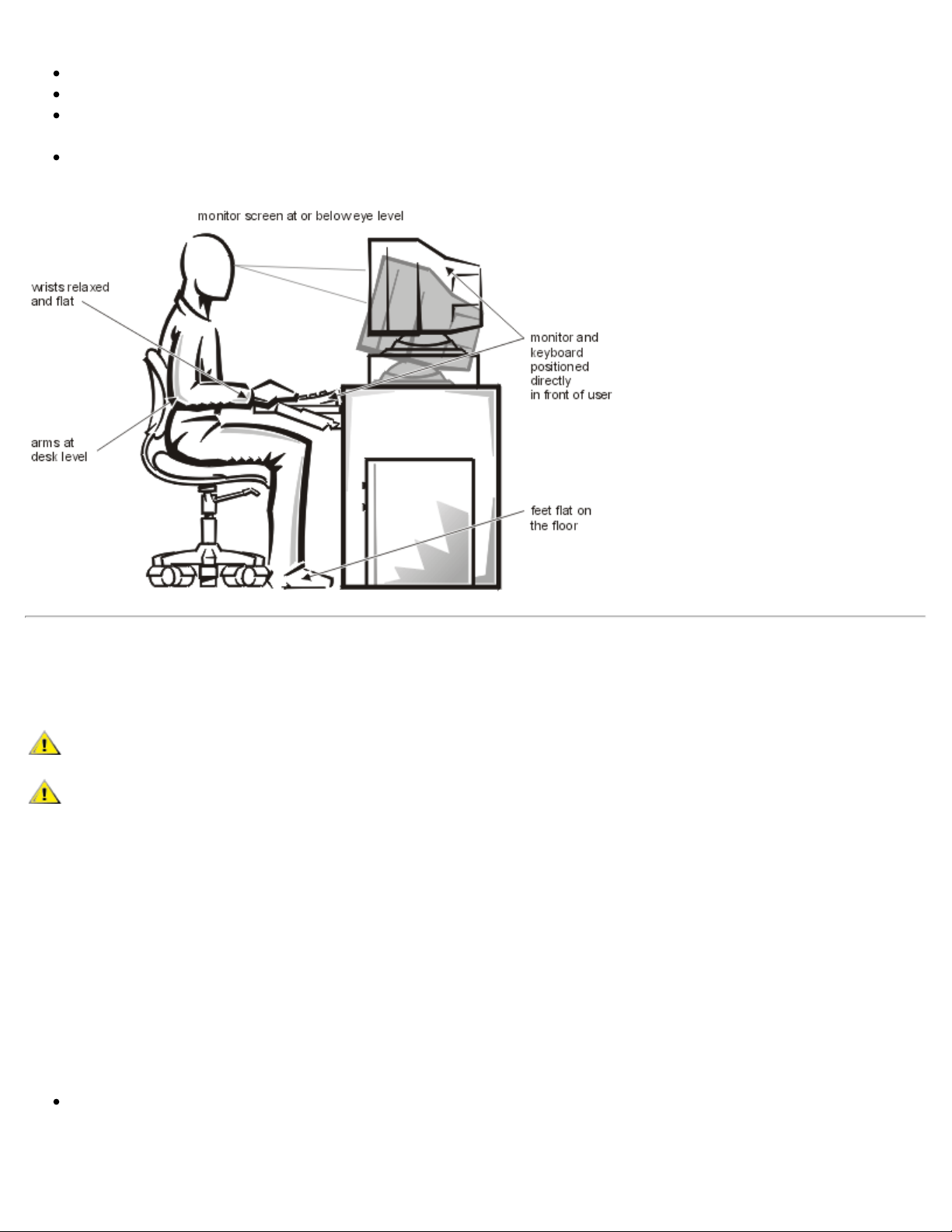
For comfort and efficiency, observe the following ergonomic guidelines when setting up and using your computer
system:
Position your system so that the monitor and keyboard are directly in front of you as you work. Special shelves
are available (from Dell and other sources) to help you correctly position your keyboard.
Set the monitor at a comfortable viewing distance (usually 510 to 610 millimeters [20 to 24 inches] from your
eyes).
Make sure the monitor screen is at eye level or slightly lower when you are sitting in front of the monitor.
Adjust the tilt of the monitor, its contrast and brightness settings, and the lighting around you (such as overhead
lights, desk lamps, and the curtains or blinds on nearby windows) to minimize reflections and glare on the
monitor screen.
Use a chair that provides good lower back support.
Keep your forearms horizontal with your wrists in a neutral, comfortable position while using the keyboard or
mouse.
Always leave space to rest your hands while using the keyboard or mouse.
Let your upper arms hang naturally at your sides.
pins. Also, before you connect a cable, make sure both connectors are correctly oriented and aligned.
Sit erect, with your feet resting on the floor and your thighs level.
When sitting, make sure the weight of your legs is on your feet and not on the front of your chair seat. Adjust your
chair's height or use a footrest, if necessary, to maintain proper posture.
Vary your work activities. Try to organize your work so that you do not have to type for extended periods of time.
When you stop typing, try to do things that use both hands.
When Working Inside Your Computer
Before you remove the computer covers, perform the following steps in the sequence indicated.
CAUTION: Do not attempt to service the computer system yourself, except as explained in this guide and
elsewhere in Dell documentation. Always follow installation and service instructions closely.
CAUTION: To help avoid possible damage to the system board, wait 5 seconds after turning off the system
before removing a component from the system board or disconnecting a peripheral device from the
computer.
1. Touch an unpainted metal surface on the chassis, such as the metal around the card-slot openings at the back of
the computer, before touching anything inside your computer.
While you work, periodically touch an unpainted metal surface on the computer chassis to dissipate any static
electricity that might harm internal components.
2. Turn off your computer and any peripherals.
3. Disconnect your computer and peripherals from their power sources. Also, disconnect any telephone or
telecommunication lines from the computer.
Doing so reduces the potential for personal injury or shock.
In addition, take note of these safety guidelines when appropriate:
When you disconnect a cable, pull on its connector or on its strain-relief loop, not on the cable itself. Some cables
have a connector with locking tabs; if you are disconnecting this type of cable, press in on the locking tabs before
disconnecting the cable. As you pull connectors apart, keep them evenly aligned to avoid bending any connector

Handle components and cards with care. Don’t touch the components or contacts on a card. Hold a card by its
edges or by its metal mounting bracket. Hold a component such as a microprocessor chip by its edges, not by its
pins
WARNING
There is a danger of a new battery exploding if it is incorrectly installed. Replace the
battery only with the same or equivalent type recommended by the manufacturer.
Discard used batteries according to the manufacturer's instructions.
Protecting Against Electrostatic Discharge
Static electricity can harm delicate components inside your computer. To prevent static damage, discharge static
electricity from your body before you touch any of your computer's electronic components, such as the microprocessor.
You can do so by touching an unpainted metal surface on the computer chassis.
As you continue to work inside the computer, periodically touch an unpainted metal surface to remove any static charge
your body may have accumulated.
You can also take the following steps to prevent damage from electrostatic discharge (ESD):
When unpacking a static-sensitive component from its shipping carton, do not remove the component from the
antistatic packing material until you are ready to install the component in your computer. Just before unwrapping
the antistatic packaging, be sure to discharge static electricity from your body.
When transporting a sensitive component, first place it in an antistatic container or packaging.
Handle all sensitive components in a static-safe area. If possible, use antistatic floor pads and workbench pads.
The following caution may appear throughout this document to remind you of these precautions:
CAUTION: See Protecting Against Electrostatic Discharge.
Back to Contents Page

Back to Contents Page
Preface: Dell® PowerEdge® 1300 Systems Installation and Troubleshooting
Guide
About This Guide | Other Documentation You May Need | Notational Conventions | Typographical Conventions |
About This Guide
This guide is intended for anyone who wants to upgrade or troubleshoot a Dell PowerEdge 1300 computer system.
Before calling Dell for technical assistance, follow the recommended procedure(s) in this guide to solve most hardware
and software problems yourself. The files are summarized as follows:
Introduction provides a brief overview of the system's service features.
Everyone should read Checking the Basics for some initial checks and procedures that you can use to solve basic
computer problems. It also directs you to the appropriate file in this guide for more detailed troubleshooting
information and procedures to solve more complex problems.
Whenever you receive an error message or code, you should read Messages and Codes. This file discusses system
messages, system beep codes, warning messages, diagnostics messages, alert log messages, and small computer
system interface (SCSI) hard-disk drive indicator codes.
If you suspect that the problems are software-related, or you are still having problems after testing the computer's
hardware, read Finding Software Solutions.
For hardware-related problems, read Running the Dell Diagnostics. Checking the Equipment and Checking Inside
the Computer provide troubleshooting procedures for equipment connected to the input/output (I/O) panel of the
computer and components inside the computer, respectively. Checking Inside the Computer also provides
information on removing the computer covers.
Installing System Board Options and Installing Drives and are intended for anyone who wants to install or remove
internal components, such as dual in-line memory modules (DIMMs), expansion cards, and SCSI devices.
Getting Help describes the help tools Dell provides to assist you should you have a problem with the computer. It
also explains how and when to call Dell for technical assistance. Getting Help also includes a Diagnostics
Checklist that you can copy and fill out as you perform the troubleshooting procedures. If you need to call Dell
for technical assistance, use the completed checklist to tell the Dell technical support representative what
procedures you performed to better help the representative give you assistance. If you must return a piece of
hardware to Dell, include a completed checklist.
Diagnostic Video Tests discusses the tests for the Video Test Group in the Dell Diagnostics to help you test the
monitor.
Jumpers, Switches, and Connectors is intended for anyone who is troubleshooting the system or is adding internal
options and needs to change jumper or switch settings.
Reference Abbreviations and Acronyms for a table of the abbreviations and acronyms used throughout this guide
and in other Dell documentation.
Other Documentation You May Need
Besides this Installation and Troubleshooting Guide, the following documentation is included with your system:
The Dell PowerEdge 1300 Systems User's Guide, which describes system features and technical specifications,
video and SCSI device drivers, the System Setup program, software support utilities, and the Resource

Configuration Utility.
The HP OpenView Network Node Manager Special Edition x.x With Dell OpenManage™ HIP x.x User's Guide,
which describes the features, requirements, installation, and basic operation of the server management software.
Refer to the software's online help for information about the alert messages issued by the software.
You may also have one or more of the following documents.
NOTE: Documentation updates are sometimes included with the system to describe changes to the system or
software. Always read these updates before consulting any other documentation because the updates often
contain information that supersedes the information in the other documents.
Operating system documentation is included with the system if you ordered the operating system software from
Dell. This documentation describes how to install (if necessary), configure, and use the operating system
software.
Documentation is included with any options you purchase separately from the system. This documentation
includes information that you need to configure and install these options in your Dell computer.
Technical information files—sometimes called "readme" files—may be installed on the hard-disk drive to provide
last-minute updates about technical changes to the system or advanced technical reference material intended for
experienced users or technicians.
Notational Conventions
The following subsections describe notational conventions used in this document.
Warnings, Cautions, and Notes
Throughout this guide, there may be blocks of text printed in bold type or in italic type. These blocks are warnings,
cautions, and notes, and they are used as follows:
WARNING: A WARNING indicates the potential for bodily harm and tells you how to avoid the problem.
CAUTION: A CAUTION indicates either potential damage to hardware or loss of data and tells you how to
avoid the problem.
NOTE: A NOTE indicates important information that helps you make better use of your computer system.
Typographical Conventions
The following list defines (where appropriate) specific elements of text and illustrates the typographical conventions
used throughout this document as visual cues for those elements:
Interface components are window titles, button and icon names, menu names and selections, and other options
that appear on the monitor screen or display. They are presented in bold.
Example: Click OK.
Keycaps, the labeling that appears on the keys on a keyboard, are enclosed in angle brackets.
Example: <Enter>
Key combinations are series of keys to be pressed simultaneously (unless otherwise indicated) to perform a single
function.

Example: <Ctrl> <Alt> <Enter>
Commands presented in lowercase bold are for reference purposes only and are not intended to be typed when
referenced.
Example: "Use the format command to . . . ."
In contrast, commands presented in the Courier New font are part of an instruction and intended to be
typed.
Example: "Type format a: to format the diskette in drive A."
Filenames and directory names are presented in lowercase bold.
Examples: autoexec.bat and c:\windows
Syntax lines consist of a command and all its possible parameters. Commands are presented in lowercase bold;
variable parameters (those for which you substitute a value) are presented in lowercase italics; constant
parameters are presented in lowercase bold. The brackets indicate items that are optional.
Example: del [drive:] [path] filename [/p]
Command lines consist of a command and may include one or more of the command's possible parameters.
Command lines are presented in the Courier New font.
Example: del c:\myfile.doc
Screen text is a message or text that you are instructed to type as part of a command (referred to as a command
line). Screen text is presented in the Courier New font.
Example: The following message appears on your screen:
No boot device available
Example: "Type md c:\dos and press < Enter >."
Variables are placeholders for which you substitute a value. They are presented in italics.
Example: DIMM x (where x represents the DIMM socket designation)
Back to Contents Page

Back to Contents Page
Introduction: Dell® PowerEdge® 1300 Systems Installation and
Troubleshooting Guide
Dell® PowerEdge® 1300 computer systems are high-speed servers that offer significant service and upgrade features.
These systems include the following service features to make troubleshooting easy and effective:
Dell Diagnostics, which checks for hardware problems (if the system can boot)
Embedded server management hardware, which monitors temperatures and voltages throughout the system and
notifies you if the system overheats or if a system cooling fan malfunctions
The Dell PowerEdge 1300 system chassis simplifies removing and replacing computer components. The power supply
enclosure rotates up out of the way to allow access to the upper system board, and the drive cage can easily be removed
from the system to facilitate drive replacement.
The following upgrade options are offered for the Dell PowerEdge 1300 systems:
An additional microprocessor
Additional memory
A variety of expansion-card options (including redundant arrays of independent disks [RAID] controller host
adapter cards)
Optional IDE CD-ROM drive, SCSI tape drive, and additional SCSI hard-disk drives
A Dell Remote Assistant Card for system management
Back to Contents Page

Back to Contents Page
Checking the Basics: Dell® PowerEdge® 1300 Systems Installation and
Troubleshooting Guide
Overview | Backing Up Files | Basic Checks | Checking Connections and Switches | Look and Listen | The System
Setup Program | The Resource Configuration Utility
Overview
If your Dell PowerEdge 1300 computer system is not working as expected, begin troubleshooting using the procedures
in this file. This file guides you through some initial checks and procedures that can solve basic computer problems. It
can also direct you to the appropriate section in this guide for detailed troubleshooting information and procedures to
solve more complex problems.
NOTE: When you see the question "Is the problem resolved?" in a troubleshooting procedure, perform the
operation that caused the problem.
Backing Up Files
If the system is behaving erratically, back up the files immediately. See the documentation that came with the operating
system for instructions on how to back up the files.
Basic Checks
The following procedure leads you through the checks necessary to solve some basic computer problems:
1. Was an alert message issued by the Dell OpenManage™ Hardware Instrumentation Package (HIP) server
management application?
Yes. Refer to your Dell OpenManage HIP documentation for information on the message.
No. Go to step 2.
2. Is the computer wet or damaged?
Yes. Go to Checking Inside the Computer.
No. Go to step 3.
3. Perform the steps in Checking Connections and Switches.
Is the problem resolved?
Yes. The power to the computer system was faulty, or the connections to the computer system were loose. You
have fixed the problem.
No. Go to step 4.

4. Follow the procedures described in Look and Listen.
Did the computer system complete the boot routine?
Yes. Go to step 5.
No. A serious malfunction may have occurred. Go to Getting Help.
5. Did you receive a system message or beep code?
Yes. Go to Messages and Codes.
No. Go to step 6.
6. Verify the settings in the System Setup program.
Is the problem resolved?
Yes. The system configuration information was incorrect. You have fixed the problem.
No. Go to step 7.
7. Run the Dell Diagnostics as described Running the Dell Diagnostics.
Checking Connections and Switches
Improperly set switches and controls and loose or improperly connected cables are the most likely source of problems
for the computer, monitor, or other peripherals (such as a printer, keyboard, mouse, or other external equipment). A
quick check of all the switches, controls, and cable connections can easily solve these problems. Figure 1, Back-Panel
Features, shows the back-panel connections on the computer. Figure 2, Front-Panel Features, shows the front-panel
controls and indicators on the computer.
Figure 1. Back-Panel Features
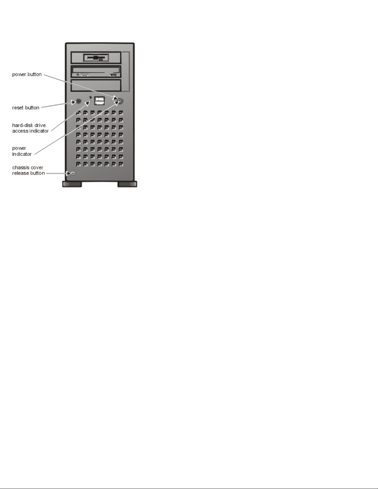
Figure 2. Front-Panel Features
Complete the following procedure to check all the connections and switches:
1. Turn off the system, including any attached peripherals (such as the monitor, keyboard, printer, external drives,
scanners, and plotters). Disconnect all the AC power cables from their electrical outlets.
2. If the computer is connected to a power strip, turn the power strip off and then on again.
Is the power strip receiving power?
Yes. Go to step 5.
No. Go to step 3.
3. Plug the power strip into another electrical outlet.
Is the power strip receiving power?
Yes. The original electrical outlet probably does not function. Use a different electrical outlet.
No. Go to step 4.
4. Plug a lamp that you know works into the electrical outlet.
Does the lamp receive power?
Yes. The power strip is probably not functioning properly. Use another power strip.
No. Go to step 5.
5. Reconnect the system to the electrical outlet or power strip.
Make sure that all connections fit tightly together.

6. Turn on the system.
Is the problem resolved?
A series of beeps See Messages and Codes.
Yes. The connections were loose. You have fixed the problem.
No. Go to step 7.
7. Is the monitor operating properly?
Yes. Go to step 8.
No. Go to Troubleshooting the Monitor.
8. Is the keyboard operating properly?
Yes. Go to step 9.
No. Go to Troubleshooting the Keyboard.
9. Are the mouse and printer operating properly?
Yes. Continue with the next section, "Look and Listen."
No. Go to Troubleshooting I/O Ports.
Look and Listen
Looking at and listening to the system is important in determining the source of a problem. Look and listen for the
indications described in Table 1, Boot Routine Indications.
Table 1. Boot Routine Indications
Look/Listen for: Action
An error message See Messages and Codes
Alert messages
from the Dell
OpenManage HIP
software
The monitor's
power indicator
The keyboard
indicators
The diskette-drive
access indicator
The server management software has detected a problem inside the computer. See the information
on alert log message in your Dell OpenManage HIP documentation.
Most monitors have a power indicator (usually on the front bezel). If the monitor's power indicator
does not come on, see Troubleshooting the Monitor.
Most keyboards have one or more indicators (usually in the upper-right corner). Press the <Num
Lock> key, the <Caps Lock> key, or the <Scroll Lock> key to toggle their respective keyboard
indicators on and off. If the indicators do not light up, see Troubleshooting the Keyboard.
The diskette-drive access indicator should quickly flash on and off when you access data on the
diskette drive. If the diskette-drive access indicator does not light up, see Troubleshooting the
Diskette Drive Subsystem.
.
The hard-disk
drive activity
indicators
The hard-disk drive activity indicators should quickly flash on and off when you access data on
the hard-disk drives. On a system running the Microsoft ® Windows NT ® operating system, you
can test the drive by opening Windows Explorer and clicking the icon for drive C. If the hard-disk
drive access indicator does not come on, see Troubleshooting SCSI Hard-Disk Drives.

An unfamiliar
constant scraping
or grinding sound
when you access a
drive
Make sure the sound is not caused by the application program you are running. The sound could
be caused by a hardware malfunction. See Getting Help for instructions on obtaining technical
assistance from Dell.
The absence of a
familiar sound
NOTE: For the full name of an abbreviation or acronym used in this table, see Abbreviations and Acronyms.
If you have not resolved the problem after looking at and listening to the computer, continue with the instructions The
System Setup Program.
When you turn on the system, you should hear the hard-disk drives spin up, and the system try to
access the start-up files from the hard-disk drive, the diskette drive, or the CD-ROM drive. See
Running the Dell Diagnostics. If the system does not boot, see Getting Help.
The System Setup Program
You can easily correct certain system problems by verifying the correct settings in the System Setup program. When
you boot the system, the system checks the system configuration information and compares it with the current hardware
configuration. If the system hardware configuration does not match the information recorded by the System Setup
program, an error message may appear on the screen.
This problem can happen if you changed the system's hardware configuration and forgot to run the System Setup
program. To correct this problem, enter the System Setup program, correct the corresponding System Setup setting, and
reboot the system. See "Using the System Setup Program" in your User's Guide for detailed instructions on using the
System Setup program.
The Resource Configuration Utility
If you are experiencing problems with the system, you may have a conflict between the information stored by the
System Setup program and the Resource Configuration Utility (RCU). Although the RCU can read changes from the
System Setup program, changes are not recorded in configuration memory until you run the RCU and save the new
information. See "Using the Resource Configuration Utility" in your User's Guide for detailed instructions on using the
RCU and saving new information.
If after using the RCU you have not resolved the problem, see Running the Dell Diagnostics.
Back to Contents Page

Back to Contents Page
drive thermal probe
Messages and Codes: Dell® PowerEdge® 1300 Systems Installation and
Troubleshooting Guide
Overview | System Messages | System Beep Codes | Warning Messages | Diagnostics Messages | Alert Log Messages
From the Dell OpenManage™ HIP Application
Overview
Application programs, operating systems, and the computer itself are capable of identifying problems and alerting you
to them. When a problem occurs, a message may appear on the monitor screen or a beep code may sound.
Several different types of messages can indicate when the system is not functioning properly:
System messages
System beep codes
Warning messages
Diagnostics messages
Alert messages
This file describes each type of message and lists the possible causes and actions you can take to resolve any problems
indicated by a message. To determine what type of message you have received, read the following sections.
System Messages
System messages alert you to a possible operating system problem or to a conflict between the software and hardware.
Table 1, System Messages, lists the system messages that can occur and the probable cause for each message.
NOTE: If you receive a system message that is not listed in the following table, check the documentation for the
application program that is running when the message appears and/or the operating system documentation for
an explanation of the message and recommended action.
Table 1. System Messages
Message Definition Probable Causes
Address mark not
found
BIOS found faulty disk sector or could not
find particular disk sector.
Faulty diskette/tape drive subsystem or harddisk drive subsystem (defective system
board), faulty interface cable or connector.
Attachment failed to
respond
Alert! Cover was
previously removed.
Alert! Hard disk
Diskette drive or hard-disk drive controller
cannot send data to associated drive.
Faulty diskette/tape drive subsystem or harddisk drive subsystem (defective system
board), faulty interface cable or connector.
Cover was previously removed. Cover was previously removed.
Hard-disk drive thermal probe has failed. No hard-disk drive thermal probe installed,

failure detected.
defective thermal probe, or thermal cable
not connected to the control panel.
Alert! One or more
of the Memory DIMMs
are out of rev.
Alert! Power supply
fan failure
detected.
Alert! Previous fan
failure.
Alert! Previous
hard-disk drive
thermal failure.
Alert! Previous
processor thermal
failure.
Alert! Previous
voltage failure.
Alert! Primary
processor is out of
rev.
System detected that one or more of the
DIMMs are not the correct revision.
DIMMs do not meet Intel® SPD 1.2
specification or 66-MHz DIMMs are
installed.
Power supply fan has failed. The power supply or system board is
defective.
System fan failed during the previous
operating session.
Hard-disk drive thermal probe failed during
previous operating session.
No fan installed, defective fan, or fan cable
not connected.
No hard-disk drive thermal probe installed,
defective thermal probe, or thermal cable
not connected to the control panel.
The microprocessor exceeded its
recommended operating temperature
during the previous operating session.
System voltage exceeded or fell below an
Operating environment is too hot (above
35°C). The system vents may be blocked,
causing the system to overheat.
Defective power supply.
acceptable threshold.
System detected that the primary processor
Processor is a type not supported by Dell.
is not the correct revision. If the system
contains more than 512 MB of RAM, this
message will be followed by a System
Halted message.
Alert! Processor
thermal probe
failure detected.
Alert! Secondary
processor is out of
rev.
Alert! Single-bit
memory error
previously detected
in XXXXh.
Alert! System fan
was not detected.
Alert! Unbuffered
and registered
SDRAM DIMMs cannot
be mixed.
Alert! Uncorrectable
memory error
previously detected
in XXXXh.
Processor or system board has failed. Faulty processor or defective system board.
System detected that the secondary
Processor is a type not supported by Dell.
processor is not the correct revision. If the
system contains more than 512 MB of
RAM, this message will be followed by a
System Halted message.
Single-bit ECC error was detected during
the previous operating session.
Faulty or improperly seated DIMMs or
defective system board.
System fan was not detected. No fan installed, defective fan, or fan cable
not connected.
Mixing of unbuffered and registered
SDRAM DIMMs is not supported.
Two different types (unbuffered and
registered) of SDRAM DIMMs have been
installed together and may not be
compatible.
Multibit ECC error was detected during the
previous operating session.
Faulty or improperly seated DIMMs or
defective system board.
Auxiliary Device
failure. Verify
that mouse and
System detected a mouse failure. Faulty mouse, or faulty mouse controller or
keyboard is attached to the mouse

keyboard are
securely attached
connector.
Hard disk failure
to connectors.
Bad command or file
name
Command entered does not exist, is faulty,
or is not in pathname specified.
Faulty command and syntax, or incorrect
filename.
Bad error-correction
code(ECC)on disk
read
Boot: Couldn't find
NTLDR
Controller has
failed
Data error
Decreasing available
memory
Diskette drive 0
seek failure
Diskette drive 1
seek failure
Diskette drive or hard-disk drive controller
detected uncorrectable read error.
Indicates a fatal error.
A nonbootable diskette formatted with
Windows NT was detected in the diskette
drive.
Hard-disk drive or associated controller is
defective. Indicates a fatal error.
System received unrecoverable data-read
error from diskette or hard-disk drive.
Indicates a fatal error.
Read/write failure during POST prevents
system from using available memory.
Diskette/tape drive controller could not
locate specific sector or track.
Faulty diskette/tape drive subsystem or hard-
disk drive subsystem (defective system
board).
A nonbootable diskette is preventing the
system from booting. Remove the diskette
to boot the system from the hard-disk drive
or from a bootable diskette.
Faulty hard-disk drive subsystem or
defective system board.
Faulty diskette, diskette drive, or hard-disk
drive.
One or more DIMMs are faulty or
improperly seated.
Faulty or improperly inserted diskette,
incorrect settings in System Setup program,
loose diskette/tape drive interface cable, or
loose power cable.
Diskette read
failure
Diskette subsystem
reset failed
Diskette write
protected
Drive not ready
ECC memory error
Gate A20 failure
General failure
Hard disk controller
failure
Hard disk drive read
failure
Failure occurred while system attempted to
read diskette.
System could not successfully issue reset
command to diskette controller.
Diskette write-protect feature was
activated.
Diskette is missing from or is improperly
inserted in diskette drive.
Uncorrectable multibit ECC memory error
is detected.
Gate A20 of the keyboard controller
malfunctioned. Indicates a fatal error.
Operating system cannot execute
command.
Hard-disk drive failed to initialize.
Indicates a fatal error.
Faulty diskette, faulty or improperly
connected diskette/tape drive interface
cable, or loose power cable.
Faulty diskette/tape drive controller
(defective system board).
Diskette write-protected.
Missing, defective, unformatted, or
improperly inserted diskette.
Faulty or improperly seated DIMMs or
defective system board.
Faulty keyboard controller (defective system
board).
Corrupted or improperly installed operating
system.
Incorrect configuration settings in System
Setup program, improperly connected hard-
disk drive cable, faulty hard-disk controller
subsystem (defective system board), or
loose power cable.
Invalid
configuration
information please run SETUP
program
System Setup program contains incorrect
system configuration settings.
Incorrect configuration settings in System
Setup program or faulty battery.
Keyboard clock line
failure
Keyboard failure
Keyboard data line
failure
Keyboard stuck key
failure
Keyboard controller
failure
Memory address line
failure at address,
read value
expecting value
Memory data line
failure at address,
read value
expecting value
Memory double word
logic failure at
address, read value
expecting value
System cannot communicate with
keyboard. Indicates a fatal error.
Keyboard/mouse controller failed.
Indicates a fatal error.
During memory test, value read at
address was incorrect.
Keyboard cable connector loose or
improperly connected, defective keyboard,
or defective keyboard/mouse controller
(defective system board).
Defective keyboard/mouse controller
(defective system board).
Faulty or improperly seated DIMMs or
defective system board.
Memory odd/even
logic failure at
address, read value
expecting value
Memory write/read
failure at address,
read value
expecting value
Memory allocation
error
Memory tests
terminated by
keystroke
Network card is not
present in the
system.
No boot device
available
No boot sector on
hard-disk drive
Software in use conflicts with operating
Faulty application program or utility.
system, application program, or utility.
Memory test did not complete. POST memory test terminated by user
pressing <Spacebar>.
System does not detect NIC. Incorrect NIC drivers installed.
System does not recognize diskette drive or
hard-disk drive from which it is trying to
boot.
Incorrect configuration settings in System
Setup program, or corrupted operating
system.
Faulty diskette, diskette/tape drive
subsystem, hard-disk drive, hard-disk drive
subsystem, or no boot disk in drive A.
Incorrect configuration settings in System
Setup program, or no operating system on
hard-disk drive.
No timer tick
interrupt
Non-system disk or
disk error
Timer on system board malfunctioning.
Indicates a fatal error.
Diskette in drive A or hard-disk drive does
not have bootable operating system
Defective system board.
Faulty diskette, diskette/tape drive
subsystem, or hard-disk drive subsystem

installed on it. (defective system board).
Not a boot diskette
Plug and Play
Configuration Error
No operating system on diskette. No operating system on diskette.
System encountered a problem in trying to
System resource conflict.
configure one or more expansion cards.
Read fault
Requested sector not
found
Reset failed
Sector not found
Seek error
Seek operation
failed
Shutdown failure
The MS-DOS® operating system cannot
read from diskette or hard-disk drive.
Faulty diskette, diskette/tape drive
subsystem, or hard-disk drive subsystem
(defective system board).
System could not find particular sector on
disk, or requested sector defective.
Faulty diskette, diskette/tape drive
subsystem, or hard-disk drive subsystem
(defective system board).
Disk reset operation failed. Improperly connected diskette/tape drive,
hard-disk drive interface cable, or power
cable.
MS-DOS is unable to locate sector on
diskette or hard-disk drive.
MS-DOS is unable to locate specific track
Defective sectors on diskette or hard-disk
drive.
Defective diskette or hard-disk drive.
on diskette or hard-disk drive.
System could not find particular address
Faulty diskette or hard-disk drive.
mark on disk.
System board is faulty. Indicates a fatal
Defective system board.
error.
System halted
Terminator/processor
card not installed!
System halted!
Time-of-day clock
stopped
Time-of-day not set
Timer chip counter 2
failed
Unexpected interrupt
in protected mode
WARNING: Dell's Disk
Monitoring System
has detected that
drive [0/1] on the
[0/1] EIDE
controller is
System locked up because the
microprocessor is not the correct revision.
System microprocessor is not a type
supported by Dell and more than 512 MB of
RAM is installed.
System does not have terminator card or
secondary microprocessor. Indicates a
fatal error.
Terminator card or secondary
microprocessor is improperly installed or is
not installed.
System battery low. Defective battery or faulty chip (defective
system board).
Time or Date settings in System Setup
program are incorrect, or the system
Incorrect Time or Date setting, or defective
system battery.
battery does not work.
Timer circuit on system board
Defective system board.
malfunctioning. Indicates a fatal error.
Keyboard/mouse controller
malfunctioning, or 1 or more DIMMs
improperly seated. Indicates a fatal error.
POST queried EIDE drive for status. Drive
Improperly seated DIMMs or faulty
keyboard/mouse controller chip (defective
system board).
Unreliable or defective drive.
detected possible error conditions.
operating outside
of normal
specifications. It
is advisable to
immediately back up
your data and
replace your harddisk drive by
calling your
support desk or
Dell Computer
Corporation.
Write fault
Write fault on
selected drive
MS-DOS cannot write to diskette or harddisk drive.
Faulty diskette or hard-disk drive.
NOTE: For the full name of an abbreviation or acronym used in this table, see Abbreviations and Acronyms.
System Beep Codes
When an error that cannot be reported on the monitor occurs during a boot routine, the computer may emit a series of
beeps that identifies the problem. The beep code is a pattern of sounds; for example, one beep followed by a second
beep and then a burst of three beeps (code 1-1-3) means that the computer was unable to read the data in nonvolatile
random-access memory (NVRAM).This information is valuable to the Dell technical support representative if you need
to call for technical assistance.
When a beep code is emitted, write it down on a copy of the Diagnostics Checklist found in Getting Help, and then look
it up in Table 2, System Beep Codes. If you are unable to resolve the problem by looking up the meaning of the beep
code, use the Dell Diagnostics to identify a more serious cause (see Running the Dell Diagnostics). If you are still
unable to resolve the problem, see Getting Help for instructions on obtaining technical assistance.
Table 2. System Beep Codes
Beep Code Error Probable Causes
1-1-3 NVRAM write/read failure Defective system board
1-1-4 BIOS checksum failure Faulty BIOS or defective system board
1-2-1 Programmable interval-timer failure Defective system board
1-2-2 DMA initialization failure Defective system board
1-2-3 DMA page register write/read failure Defective system board
1-3-1 Main-memory refresh verification failure Faulty or improperly seated DIMM or defective
system board
1-3-2 No 100-MHz DIMM installed No 100-MHz DIMM installed or faulty or
improperly seated DIMM
1-3-3 Chip or data line failure in the first 64 KB of
Faulty or improperly seated DIMM
main memory
1-3-4 Odd/even logic failure in the first 64 KB of
Faulty or improperly seated DIMM
main memory
1-4-1 Address line failure in the first 64 KB of
main memory
Faulty or improperly seated DIMM
1-4-2 Parity failure in the first 64 KB of main
memory
2-1-1 through
2-4-4
3-1-1 Slave DMA-register failure Defective system board
3-1-2 Master DMA-register failure Defective system board
3-1-3 Master interrupt-mask register failure Defective system board
3-1-4 Slave interrupt-mask register failure Defective system board
3-2-4 Keyboard-controller test failure Faulty keyboard controller (defective system board)
3-3-4 Screen initialization failure
3-4-1 Screen-retrace test failure
3-4-2 Search for video ROM failure
Bit failure in the first 64 KB of main memory Faulty or improperly seated DIMM
Faulty or improperly seated DIMM
Faulty video subsystem (defective graphics adapter
card)
Faulty video subsystem (defective graphics adapter
card)
Faulty video subsystem (defective graphics adapter
card)
4-2-1 No timer tick Defective system board
4-2-2 Shutdown failure Defective system board
4-2-3 Gate A20 failure Defective system board
4-2-4 Unexpected interrupt in protected mode Defective system board
4-3-1 Memory failure above address 0FFFFh Faulty or improperly seated DIMMs
4-3-3 Timer-chip counter 2 failure Defective system board
4-3-4 Time-of-day clock stopped Bad battery or defective system board
4-4-1 Serial/parallel port test failure Faulty I/O chip (defective system board)
NOTE: For the full name of an abbreviation or acronym used in this table, see Abbreviations and Acronyms
.
Warning Messages
A warning message alerts you to a possible problem and asks you to take corrective action before the system continues a
task. For example, before you format a diskette, a message may warn you that you may lose all data on the diskette, as
a way to protect against inadvertently erasing or writing over the data. These warning messages usually interrupt the
procedure and require you to respond by typing y (yes) or n (no).
NOTE: Warning messages are generated by either the application program or the operating system. See Finding
Software Solutions and the documentation that accompanied the operating system and application program for
more information on warning messages.

Diagnostics Messages
When you run a test group or subtest in the Dell Diagnostics, an error message may result. These particular error
messages are not covered in this file. Record the message on a copy of the Diagnostics Checklist found in Getting Help
and then follow the instructions in that file for obtaining technical assistance.
Alert Log Messages From the Dell OpenManage™ HIP Application
The Dell OpenManage Hardware Instrumentation Package (HIP) server management application program generates
alert messages that appear in the Simple Network Management Protocol (SNMP) trap log file. To see the trap log,
select any enterprise under the SNMP trap log icon. (More information about the Alert Log window and options is
provided in the Dell OpenManage HIP online help and the HP OpenView Network Node Manager Special Edition x.x
With Dell OpenManage™ HIP x.x User's Guide.)
Alert log messages consist of information, status, warning, and failure messages for drive, temperature, fan, and power
conditions. They can assist you with identifying a problem and may provide you with information to help you resolve
the problem.
Back to Contents Page

Back to Contents Page
Using Software
Finding Software Solutions: Dell® PowerEdge® 1300 Systems Installation
and Troubleshooting Guide
Overview | Installing and Configuring Software | Using Software
Overview
Because most computer systems have several application programs installed in addition to the operating system,
isolating a software problem can be confusing. Software errors can also appear to be hardware malfunctions at first.
Software problems can result from the following circumstances:
Improper installation or configuration of a program
Input errors
Device drivers that may conflict with certain application programs
Interrupt conflicts between devices
You can confirm that a computer system problem is caused by software by running the System Set Test Group as
described in Running the Dell Diagnostics. If all tests in the test group are completed successfully, the error condition is
most likely caused by software.
This file provides some general guidelines for analyzing software problems. For detailed troubleshooting information on
a particular program, see the documentation that accompanied the software or consult the support service for the
software.
Installing and Configuring Software
You should use virus-scanning software to check newly acquired programs and files for viruses before installing the
programs on the computer's hard-disk drive. Viruses, which are pieces of code that can replicate themselves, can
quickly use all available system memory, damage and/or destroy data stored on the hard-disk drive, and permanently
affect the performance of the programs they infect. Several commercial virus-scanning programs are available for
purchase, and most bulletin board services (BBSs) archive freely distributed virus-scanning programs that you can
download with a modem.
Before installing a program, you should read its documentation to learn how the program works, what hardware it
requires, and what its defaults are. A program usually includes installation instructions in its accompanying
documentation and a software installation routine on its program diskettes.
The software installation routine assists users in transferring the appropriate program files to the computer's hard-disk
drive. Installation instructions may provide details about how to configure the operating system to successfully run the
program. You should always read the installation instructions before running a program's installation routine.
When you run the installation routine, you should be prepared to respond to prompts for information about how the
computer's operating system is configured, what type of computer you have, and what peripherals are connected to the
computer.
The following subsections discuss errors that can occur as a result of software operation or configuration.
Error Messages
Error messages can be produced by an application program, the operating system, or the computer. Messages and Codes
discusses the error messages that are generated by the computer. If you receive an error message that is not listed there,
check the operating system or application program documentation.
Input Errors
If a specific key or set of keys is pressed at the wrong time, a program may give you unexpected results. See the
documentation that came with the application program to make sure that the values or characters you are entering are
valid.
Make sure that the operating environment is set up to accommodate the programs you use. Keep in mind that whenever
you change the parameters of the computer's operating environment, you may affect the successful operation of the
programs. Sometimes, after modifying the operating environment, you may need to reinstall a program that no longer
runs properly.
Program Conflicts
Some programs may leave portions of their setup information behind, even though you have exited from them. As a
result, other programs cannot run. Rebooting the system can confirm whether or not these programs are the cause of the
problem.
There are also programs that use specialized subroutines called device drivers that can cause problems with the
computer system. For example, a variation in the way the data is sent to the monitor may require a special screen driver
program that expects a certain kind of video mode or monitor. In such cases, you may have to develop an alternative
method of running that particular program—by creating a start-up file made especially for that program, for example.
Call the support service for the software you are using to help you with this problem.
Avoiding Interrupt Assignment Conflicts
Problems can arise if two devices attempt to use the same interrupt request (IRQ) line. To avoid this type of conflict,
check the documentation for the IRQ line's default for each installed expansion card. Then consult Table 1, IRQ Line
Assignment Defaults, to configure the card for one of the available IRQ lines.
Table 1. IRQ Line Assignment Defaults
IRQ Line Used By/Available
IRQ0 Used by the system timer
IRQ1 Used by the keyboard to signal that the output buffer is full
IRQ2 Used by interrupt controller 1 to enable IRQ8 through IRQ15
IRQ3 Used by serial port 2 (COM2 and COM4)
IRQ4 Used by serial port 1 (COM1 and COM3)
IRQ5 Available unless used by a secondary parallel port
IRQ6 Used by the diskette drive controller

IRQ7 Used by the primary parallel port
IRQ8 Used by the RTC
IRQ9 Used for power management functions
IRQ10 Available
IRQ11 Available
IRQ12 Used by the PS/2 mouse port unless the mouse is disabled in the System Setup program
IRQ13 Used by the math coprocessor
IRQ14 Available
IRQ15 Available
NOTE: For the full name of an abbreviation or acronym used in this table, see Abbreviations and Acronyms.
Back to Contents Page
Back to Contents Page
Running the Dell Diagnostics: Dell® PowerEdge® 1300 Systems Installation
and Troubleshooting Guide
Overview | Features of the Dell Diagnostics | When to Use the Dell Diagnostics | Starting the Dell Diagnostics | How to
Use the Dell Diagnostics | Confirming the System Configuration Information | How to Use the Main Menu | Main
Menu Options | Tests in the Dell Diagnostics | Error Messages | RAM Test Group | System Set Test Group | Video Test
Group | Keyboard Test Group | Mouse Test | Diskette Drives Test Group | Serial/Infrared Ports Test Group | Parallel
Ports Test Group | SCSI Devices Test Group
Overview
Unlike many diagnostic programs, the Dell Diagnostics helps you check the computer's hardware without any additional
equipment and without destroying any data. By using the diagnostics, you can have confidence in the computer
system's operation. If you find a problem that you cannot solve by yourself, the diagnostic tests can provide you with
important information you will need when talking to Dell's technical assistance representative.
CAUTION: Use the Dell Diagnostics to test only Dell computer systems. Using this program with other
computers may cause incorrect computer responses or result in error messages.
Features of the Dell Diagnostics
The Dell Diagnostics provides a series of menus and options from which you choose particular test groups or subtests.
You can also control the sequence in which the tests are run. The diagnostic test groups or subtests also have these
helpful features:
Options that let you run tests individually or collectively
An option that allows you to choose the number of times a test group or subtest is repeated
The ability to display or print test results or to save them in a file
Options to temporarily suspend testing if an error is detected or to terminate testing when an adjustable error limit
is reached
A menu option, called About, that briefly describes each test and its parameters
Status messages that inform you whether test groups or subtests are completed successfully
Error messages that appear if any problems are detected
When to Use the Dell Diagnostics
Whenever a major component or device in the computer system does not function properly, you may have a component
failure. As long as the microprocessor and the input and output components of the computer system (the monitor,
keyboard, and diskette drive) are working, you can use the Dell Diagnostics. If you know what component(s) you need
to test, simply select the appropriate diagnostic test group(s) or subtest(s). If you are unsure about the scope of the
problem, read the rest of the information in this file.
Starting the Dell Diagnostics

You can run the Dell Diagnostics from either the utility partition on your hard-disk drive or from a diskette that you
create from the Dell OpenManage™ Server Assistant CD.
How to Use the Dell Diagnostics
To run the diagnostics from the utility partition, follow these steps:
1. Start the utility partition by pressing <F10> during the power-on self-test (POST).
2. From the utility partition's main menu, select the Run System Diagnostics option from Run System Utilities.
See "Utility Partition" in "Using the Dell OpenManage Server Assistant" in the Dell PowerEdge 1300 Systems User's
Guide for additional information about the utility partition.
To run the Dell Diagnostics from a diskette, perform the following steps:
1. Create a diagnostics diskette using the Dell OpenManage Server Assistant CD.
See "Utility Partiton" in "Using the Dell OpenManage Server Assistant CD" in the User's Guide for information
on creating diskettes.
2. Boot the system from the diagnostics diskette.
If the system fails to boot, see Getting Help for instructions on obtaining technical assistance.
NOTE: Before you read the rest of this file, you may want to start the Dell Diagnostics so you can see it on your
monitor screen.
When you start the diagnostics, the Dell logo screen appears, followed by a message telling you that the diagnostics is
loading. Before the diagnostics loads into memory, a program tests the random-access memory (RAM) that will be
used by the diagnostics.
If no errors are found in RAM, the diagnostics loads, and the DIAGNOSTICS menu appears (see Figure 1, Diagnostics
Menu). The menu allows you to run all or specific diagnostic tests or to exit the Dell Diagnostics.
For a quick check of the system, select RUn Quick Tests. This option runs only the subtests that do not require user
interaction and that do not take a long time to run. Dell recommends that you choose this option first to increase the
odds of tracing the source of the problem quickly. For a complete check of the system, select Run All Tests. To check
a particular area of the system, select RuN Specific Tests.
To select an option from the DIAGNOSTICS menu, highlight the option and press <Enter>, or press the key that
corresponds to the highlighted letter in the option you choose.
Figure 1. Diagnostics Menu
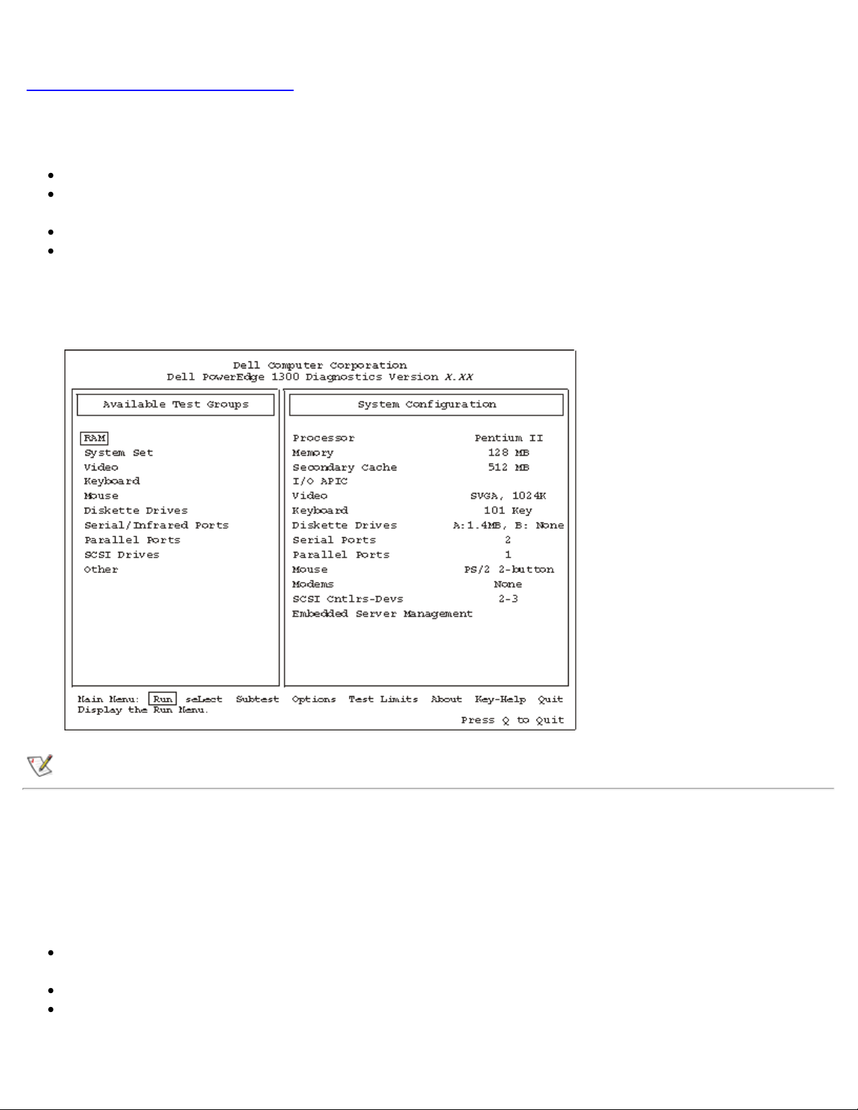
When you select RuN Specific Tests from the DIAGNOSTICS menu, the main screen of the diagnostics appears.
Figure 2, Dell Diagnostics Main Screen, shows a sample main screen; the actual text on your system may vary
depending on your system configuration.
Information on the main screen of the diagnostics is presented in the following four areas:
Two lines at the top of the main screen identify the diagnostics and give its version number.
On the left side of the screen, the Available Test Groups area lists the diagnostic test groups in the order they
will run if you select All under the Run submenu. Press the up- or down-arrow key to highlight a test group.
On the right side of the screen, the System Configuration area lists the computer's current hardware settings.
Two lines at the bottom of the screen make up the Main Menu area. The first line lists the menu options you can
select; press the left- or right-arrow key to highlight an option. The second line gives information about the
highlighted option.
Figure 2. Dell Diagnostics Main Screen
NOTE: The options displayed on the screen should reflect the hardware configuration of the computer system.
Confirming the System Configuration Information
When you boot the system from the diagnostics diskette, the Dell Diagnostics checks the system configuration
information and displays it in the System Configuration area on the main screen.
The following sources supply this configuration information for the Dell Diagnostics:
The system configuration information settings (stored in nonvolatile RAM [NVRAM]) that you selected while
using the System Setup program
Identification tests of the microprocessor, the video controller, the keyboard controller, and other key components
Basic input/output system (BIOS) configuration information temporarily saved in RAM
Do not be concerned if the System Configuration area does not list the names of all the components or devices you

know are part of the computer system. For example, you may not see a printer listed, although you know one is
attached to the computer. Instead, the printer is listed as a parallel port. The computer recognizes the parallel port as
LPT1, which is an address that tells the computer where to send outgoing information and where to look for incoming
information. Because the printer is a parallel communications device, the computer recognizes the printer by its LPT1
address and identifies it as a parallel port.
How to Use the Main Menu
The Main Menu at the bottom of the screen provides options that enable you to select and run specific diagnostic tests
from the diagnostics main screen. Options on the menu are selectable using the left- and right-arrow keys. As you move
from one menu option to another, a brief explanation of the highlighted option appears on the bottom line of the screen.
If you want more information about a test group or subtest, move the highlight to the About option and press <Enter>.
After reading the information, press <Esc> to return to the previous screen.
Main Menu Options
Eight options are listed in the Main Menu of the diagnostics main screen: Run, seLect, Subtest, Options, Test Limits,
About, Key-Help, and Quit. (An additional option, Display the Run Menu, returns you to the DIAGNOSTICS menu
shown in Figure 1, Diagnostics Menu.)
NOTE: Before running any test groups or subtests (by selecting Run), you should consider setting global
parameters within Options. Global parameters offer you greater control over how the test groups or subtests are
run and how results are reported.
There are two ways to select a menu option:
Look on the screen to see which letter in the option is capitalized, and type that letter (for example, type r to
select the Run option).
Move the highlight to the option you wish to select by pressing the left- or right-arrow key, and then press
<Enter>.
Whenever one of the eight options is selected, additional choices become available.
The following subsections explain the menu options as listed from left to right in the Main Menu.
Run
Run displays five options: One, Selected, All, Key-Help, and Quit Menu. If you select One, all the subtests within the
highlighted test group are run. If you choose Selected, only the selected test groups or the subtests that you selected
within the test groups are run. If you select All, all of the subtests in all of the test groups are run. (The test groups or
subtests are run in the same order as they are listed.)
Key-Help displays a list of key controls available for the particular option you have chosen. The Quit Menu option
returns you to the previous menu.
seLect
The seLect option allows you to select individual test groups to tailor the testing process to your particular needs. You
can choose one or more test groups and run them sequentially or individually. When you choose seLect, five options
are displayed: All, One, Clear All, Key-Help, and Quit Menu.

To select all the test groups, press <Enter> when All is highlighted in the seLect menu.
To select an individual test group, highlight the test group and press <Spacebar> or highlight One and press <Enter>.
Press the up- or down-arrow key to change the highlighted test group.
To reverse a test group selection, highlight the test group and press <Spacebar>. To clear all selections, select Clear All.
Key-Help displays a list of key controls available for the particular option you have chosen. Quit Menu returns you to
the previous menu.
Subtest
Most of the test groups consist of several subtests. Use the Subtest option to select individual subtests within the test
group(s).
When you select Subtest, many of the same options as those on the Main Menu are displayed: Run, Select, Options,
Test Limits, About, Key-Help, and Quit Menu. Each of these options is explained in the following subsections.
Run Under Subtest
Run in the Subtest menu displays five options: One, Selected, All, Key-Help, and Quit Menu. If you select One, only
the highlighted subtest is run. If you select Selected, only the selected subtests are run. If you select All, all of the
subtests listed on the screen are run. (The subtests are run in the same order as they are listed.)
The Key-Help option displays a list of key controls available. The Quit Menu option returns you to the previous menu.
Select Under Subtest
Select in the Subtest menu allows you to select individual subtests to tailor the testing process to your particular needs.
You can choose one or more subtests from the list. When you choose Select, five options are displayed: All, One,
Clear All, Key-Help, and Quit Menu.
To select all the subtests, press <Enter> when All is highlighted in the Select menu. To select an individual subtest,
highlight the subtest and press <Spacebar> or highlight One and press <Enter>. Press the up- or down-arrow key to
highlight a subtest to be selected.
To reverse a subtest selection, highlight the subtest and press <Spacebar>. To clear all selections, select Clear All.
Key-Help displays a list of key controls available. The Quit Menu option returns you to the previous menu.
Options Under Subtest
Options in the Subtest menu functions the same way as Options in the Main Menu. For information on this option,
see Options
.
Test Limits Under Subtest
Test Limits in the Subtest menu functions the same way as the Test Limits option in the Main Menu. For information
on this option, see Test Limits
About Under Subtest
.
 Loading...