

Page 1

Dell PowerConnect W-Series
Instant Access Point
User Guide
Page 2

Copyright
®
© 2011 Aruba Networks, Inc. Aruba Networks trademarks include , Aruba Networks
registered Aruba the Mobile Edge Company logo, and Aruba Mobility Management System
®
. Dell™, the DELL™ logo, and PowerConnect™ are
, Aruba Wireless Networks®, the
trademarks of Dell Inc.
All rights reserved. Specifications in this manual are subject to change without notice.
Originated in the USA. All other trademarks are the property of their respective owners.
Open Source Code
Certain Aruba products include Open Source software code developed by third parties, including software code subject to the GNU General
Public License (GPL), GNU Lesser General Public License (LGPL), or other Open Source Licenses. The Open Source code used can be found at
this site:
http://www.arubanetworks.com/open_source
Legal Notice
The use of Aruba Networks, Inc. switching platforms and software, by all individuals or corporations, to terminate other vendors’ VPN client
devices constitutes complete acceptance of liability by that individual or corporation for this action and indemnifies, in full, Aruba Networks, Inc.
from any and all legal actions that might be taken against it with respect to infringement of copyright on behalf of those vendors.
Dell PowerConnect W-Instant Access Point 5.0.3.0-1.1.0.0 | User Guide 0510992-01 | July 2011
Page 3

Contents
About this Guide ..................................................................................................................................................... 13
Objective ............................................................................................................................................13
Intended Audience...........................................................................................................................13
Conventions.......................................................................................................................................13
Contacting Support .......................................................................................................................... 14
Chapter 1 W-IAP Internal Antenna Patterns .................................................................................. 15
W-IAP92 and W-IAP93 Antenna Patterns....................................................................................15
W-IAP105 Antenna Pattern............................................................................................................. 16
Chapter 2 Initial Configuration........................................................................................................... 17
Initial Setup........................................................................................................................................ 17
Pre-Installation Checklist........................................................................................................17
Connecting the W-IAP to a Power Source .................................................................................. 18
Assigning an IP Address to the W-IAP.........................................................................................18
Connecting to the Provisioning Wi-Fi network............................................................................18
Login into Instant User Interface ...................................................................................................19
Specifying the Country Code .......................................................................................................... 20
Chapter 3 Instant User Interface....................................................................................................... 21
Understanding the Instant UI Layout ............................................................................................ 21
Banner........................................................................................................................................22
Search ........................................................................................................................................ 22
Tabs ............................................................................................................................................ 22
Networks Tab.................................................................................................................... 22
Access Points Tab ........................................................................................................... 23
Clients Tab......................................................................................................................... 23
Links............................................................................................................................................24
New version available.....................................................................................................24
Users .................................................................................................................................. 24
Settings ..............................................................................................................................25
Servers............................................................................................................................... 26
Roles................................................................................................................................... 26
Maintenance.....................................................................................................................26
Support............................................................................................................................... 26
Help..................................................................................................................................... 28
Logout................................................................................................................................. 28
Monitoring .........................................................................................................................28
Client Alerts....................................................................................................................... 31
IDS ...................................................................................................................................... 32
Language ...........................................................................................................................33
AirWave Setup.................................................................................................................. 33
Pause/Resume..................................................................................................................33
Views .......................................................................................................................................... 33
Chapter 4 Wireless Network.............................................................................................................. 35
Network Types..................................................................................................................................35
Employee Network ................................................................................................................... 35
Dell PowerConnect W-Instant Access Point 5.0.3.0-1.1.0.0 | User Guide | 3
Page 4

Adding an Employee Network........................................................................................ 35
Voice Network .......................................................................................................................... 41
Adding a Voice Network .................................................................................................41
Guest Network .......................................................................................................................... 44
Adding a Guest Network.................................................................................................44
Editing a Network ..................................................................................................................... 47
Deleting a Network .................................................................................................................. 47
Bandwidth Contracts ....................................................................................................................... 48
Chapter 5 Mesh Network ................................................................................................................... 49
Mesh Instant Access Points........................................................................................................... 49
Mesh Portals ............................................................................................................................. 49
Mesh Points............................................................................................................................... 49
Instant Mesh Setup..........................................................................................................................50
Chapter 6 Managing IAPs .................................................................................................................. 53
Auto Join Mode ................................................................................................................................ 53
Disabling Auto Join Mode.......................................................................................................53
LED Display........................................................................................................................................54
Terminal Access...............................................................................................................................54
Syslog Server ................................................................................................................... ................. 55
Adding an W-IAP to the Network .................................................................................................. 55
Removing an W-IAP from the Network ........................................................................................ 56
Editing W-IAP Settings .................................................................................................................... 56
Changing W-IAP Name ........................................................................................................... 56
Changing IP Address of the W-IAP....................................................................................... 57
Configuring Adaptive Radio Management........................................................................... 58
Configuring an External Antenna........................................................................................... 59
Migrating from a Virtual Controller Managed Network to Mobility Controller Managed
Network...................................................................................................................................... 59
Rebooting the W-IAP ....................................................................................................................... 61
Firmware Image Server in Cloud Network...................................................................................61
Automatic Firmware Image Check and Upgrade................................................................ 62
Upgrading to the new OS version.......................................................................................... 62
Manual Firmware Image Check and Upgrade.....................................................................63
Chapter 7 NTP Server ......................................................................................................................... 65
Configuring an NTP Server ............................................................................................................. 65
Chapter 8 Virtual Controller................................................................................................................ 67
Master Election Protocol ................................................................................................................ 67
Virtual Controller IP Address..........................................................................................................67
Specifying Name and IP Address for the Virtual Controller..............................................67
Configuring the DHCP Server ................................................................................................. 68
Chapter 9 Authentication.................................................................................................................... 69
Authentication Methods in Dell Instant........................................................................................69
802.1X Authentication ...................................................................................................................... 69
Internal RADIUS Server...........................................................................................................69
External RADIUS Server..........................................................................................................70
Configuring an External RADIUS Server ...................................................................... 70
Enabling Instant RADIUS ................................................................................................ 71
RADIUS Server Authentication with VSA.............................................................................71
List of supported VSA’s ...................................................................................................72
Management Authentication Settings.......................................................................... 74
4 | Dell PowerConnect W-Instant Access Point 5.0.3.0-1.1.0.0 | User Guide
Page 5

Captive Portal....................................................................................................................................75
Internal Captive Portal.............................................................................................................75
Configuring Internal Captive Portal Authentication when Adding a Guest Network
75
Configuring Internal Captive Portal Authentication when Editing a Guest Network
76
Configuring Internal Captive Portal with External Radius Server Authentication
when Adding a Guest Network......................................................................................77
Customizing a Splash Page ............................................................................................ 78
Disabling Captive Portal authentication.......................................................................79
External Captive Portal ............................................................................................................ 80
Configuring External Captive Portal Authentication when Adding a Guest Network
80
Configuring External Captive Portal Authentication when editing a Guest Network
80
MAC Authentication......................................................................................................................... 81
Configuring MAC Authentication........................................................................................... 81
Certificates ........................................................................................................................................ 82
Loading Certificates ................................................................................................................. 82
Chapter 10 Role Derivation................................................................................................................... 85
User Roles.......................................................................................................................................... 85
Creating a New User Role.......................................................................................................85
Creating Role Assignment Rules............................................................................................86
Chapter 11 Guest DMZ.......................................................................................................................... 89
Chapter 12 Instant Firewall .................................................................................................................. 91
Service Options................................................................................................................................. 91
Destination Options..........................................................................................................................93
Example Access Rules .................................................................................................................... 93
Allow TCP service to a particular network .......................................................................... 93
Allow PoP3 service to a particular server............................................................................94
Deny FTP service except to a particular server.................................................................. 95
Deny bootp service except to a particular network........................................................... 96
Chapter 13 Content Filtering................................................................................................................. 99
Enabling Content Filtering ............................................................................................................... 99
Chapter 14 OS Fingerprinting............................................................................................................. 101
Chapter 15 Adaptive Radio Management........................................................................................ 103
ARM Features ................................................................................................................................. 103
Channel or Power Assignment.............................................................................................103
Voice Aware Scanning..........................................................................................................103
Load Aware Scanning ........................................................................................................... 103
Band Steering Mode..............................................................................................................103
Air Time Fairness....................................................................................................................104
Air Time Fairness Modes ..............................................................................................104
Customize valid channels......................................................................................................104
Min transmit power................................................................................................................104
Max transmit power...............................................................................................................104
Monitoring the Network with ARM ..................................................................................... 105
ARM Metrics ........................................................................................................................... 105
Configuring Administrator Assigned Radio Settings for IAP...........................................105
Dell PowerConnect W-Instant Access Point 5.0.3.0-1.1.0.0 | User Guide | 5
Page 6

Chapter 16 Intrusion Detection System ........................................................................................... 107
Rogue AP Detection and Classification......................................................................................107
Rogue Containment................................................................................................................107
Containment Methods ........................................................................................................... 107
Chapter 17 SNMP ................................................................................................................................ 109
SNMP Parameters for IAP............................................................................................................109
Chapter 18 Airwave Integration and Management ....................................................................... 113
AirWave Features........................................................................................................................... 113
Image Management...............................................................................................................113
W-IAP and Client Monitoring ............................................................................................... 113
Template Based Configuration.............................................................................................113
Trending Reports .................................................................................................................... 114
Intrusion Detection System .................................................................................................. 114
Configuring AirWave...................................................................................................................... 114
Creating your Organization String ....................................................................................... 114
The Shared Key.......................................................................................................................115
Entering the Organization String and AMP Information into the IAP .................... 115
Airwave Discovery through DHCP Option.......................................................................... 115
Chapter 19 Monitoring ........................................................................................................................ 117
Virtual Controller View................................................................................................................... 117
Monitoring Link ....................................................................................................................... 117
Info ............................................................................................................................................ 118
RF Dashboard..........................................................................................................................118
Usage Trends .......................................................................................................................... 118
Client Alerts Link.....................................................................................................................119
IDS Link .................................................................................................................................... 119
Network View.................................................................................................................................. 120
Info ............................................................................................................................................ 120
Usage Trends .......................................................................................................................... 120
Instant Access Point View............................................................................................................122
Info ............................................................................................................................................ 123
RF Dashboard..........................................................................................................................123
RF Trends ................................................................................................................................. 123
Usage Trends .......................................................................................................................... 125
Client View.......................................................................................................................................125
Info ............................................................................................................................................ 126
RF Dashboard..........................................................................................................................126
RF Trends ................................................................................................................................. 126
Mobility Trail............................................................................................................................ 129
Chapter 20 Alert Types and Management....................................................................................... 131
Chapter 21 User Database ................................................................................................................. 133
Adding a User.................................................................................................................................. 133
Editing User Settings..............................................................................................................133
Deleting a User ....................................................................................................................... 134
Chapter 22 Regulatory Domain.......................................................................................................... 135
Country Codes List.......................................................................................................................... 135
Appendix A Abbreviations .................................................................................................................. ................ 139
6 | Dell PowerConnect W-Instant Access Point 5.0.3.0-1.1.0.0 | User Guide
Page 7

Figures
Figure 1 W-IAP93 Antenna Pattern............................................................................................................... 15
Figure 2 W-IAP105 Antenna Pattern............................................................................................................. 16
Figure 3 Connecting to Provisioning Wi-Fi network - Microsoft Windows............................................ 19
Figure 4 Connecting to Provisioning Wi-Fi network - MAC OS................................................................19
Figure 5 Instant User Interface Login Screen.............................................................................................19
Figure 6 Specifying the Country Code .......................................................................................................... 20
Figure 7 Basic Sections in the Instant UI..................................................................................................... 21
Figure 8 Networks Tab - Compressed View and Expanded View ........................................................... 22
Figure 9 Access Points Tab - Compressed View and Expanded View ................................................... 23
Figure 10 Client Tab - Compressed View and Expanded View................................................................... 24
Figure 11 Users Box........................................................................................................................................... 25
Figure 12 Settings Link - Default View............................................................................................................ 25
Figure 13 Maintenance Link - Default View .................................................................................................. 26
Figure 14 Support Box.......................................................................................................................................28
Figure 15 Help Link............................................................................................................................................. 28
Figure 16 Monitoring on Instant UI ................................................................................................................. 29
Figure 17 Info Section in the Monitoring Pane ............................................................................................. 29
Figure 18 RF Dashboard in the Monitoring Pane..........................................................................................29
Figure 19 Usage Trends Section in the Monitoring Pane ........................................................................... 31
Figure 20 Client Alerts link on Instant UI........................................................................................................31
Figure 21 Client Alerts Link...............................................................................................................................32
Figure 22 Intrusion Detection on Instant UI................................................................................................... 32
Figure 23 AirWave Setup Link – AirWave Configuration ............................................................................ 33
Figure 24 Adding an Employee Network - Basic Info Tab .......................................................................... 36
Figure 25 Band and Hide SSID Settings.........................................................................................................37
Figure 26 Security Tab - Enterprise ................................................................................................................ 39
Figure 27 Security Tab - Personal...................................................................................................................40
Figure 28 Security Tab - Open ......................................................................................................................... 40
Figure 29 Adding an Employee Network - Access Rules Tab - Network ................................................. 41
Figure 30 Adding a Voice Network - Basic Info Tab....................................................................................42
Figure 31 Adding a Guest Network - Basic Info Tab.................................................................................... 44
Figure 32 Adding a Guest Network - Splash Page Settings ....................................................................... 46
Figure 33 Configuring a Splash Page - Encryption Settings ....................................................................... 47
Figure 34 Open Instant SSID ............................................................................................................................ 50
Figure 35 Untrusted Connection Window......................................................................................................50
Figure 36 Login Window ................................................................................................................................... 51
Figure 37 Mesh Portal ............................................................................................................. .......................... 51
Figure 38 Disabling Auto Join Mode............................................................................................................... 53
Figure 39 LED Display........................................................................................................................................54
Figure 40 Terminal Access...............................................................................................................................54
Figure 41 Syslog Server ........................................................................................................... ......................... 55
Figure 42 Adding an W-IAP to the Instant Network..................................................................................... 55
Figure 43 Entering the MAC Address for the New W-IAP .......................................................................... 55
Figure 44 Editing W-IAP Settings .................................................................................................................... 56
Dell PowerConnect W-Instant Access Point 5.0.3.0-1.1.0.0 | User Guide | 7
Page 8

Figure 45 Changing W-IAP Name ................................................................................................................... 57
Figure 46 Configuring W-IAP Settings - Connectivity Tab .......................................................................... 57
Figure 47 Configuring W-IAP Connectivity Settings - Specifying Static Settings................................... 58
Figure 48 Configuring W-IAP Radio Settings Mode - Access....................................................................58
Figure 49 Configuring W-IAP External Antenna Settings............................................................................ 59
Figure 50 Maintenance Box ............................................................................................................................. 60
Figure 51 Maintenance - Convert Tab............................................................................................................60
Figure 52 Confirm Access Point Conversion Box .........................................................................................60
Figure 53 Rebooting the W-IAP ....................................................................................................................... 61
Figure 54 Automatic Image Check - New Version Available Link ............................................................. 62
Figure 55 New Version Available Box ............................................................................................................ 62
Figure 56 Manual Image Check.......................................................................................................................63
Figure 57 Configuring NTP Server................................................................................................................... 65
Figure 58 Specifying Virtual Controller Name and IP Address .................................................................. 67
Figure 59 Configuring the DHCP Server ......................................................................................................... 68
Figure 60 Configuring External RADIUS Server ............................................................................................ 71
Figure 61 Enabling Instant RADIUS................................................................................................................. 71
Figure 62 Management Authentication Settings..........................................................................................75
Figure 63 Configuring Captive Portal when Adding A Guest Network...................................................... 76
Figure 64 Configuring Captive Portal when Editing a Guest Network....................................................... 77
Figure 65 Configuring Internal Captive Portal with External Radius Server Authentication.................78
Figure 66 Customizing a Splash Page............................................................................................................. 79
Figure 67 Disabling Captive Portal Authentication....................................................................................... 79
Figure 68 Configuring External Captive Portal when Adding a Guest Network ...................................... 80
Figure 69 Configuring External Captive Portal Authentication when editing a Guest Network ........... 81
Figure 70 Configuring MAC Authentication...................................................................................................82
Figure 71 Loading Certificates ......................................................................................................................... 83
Figure 72 Access Tab - Instant User Role Settings...................................................................................... 85
Figure 73 Creating a New User Role............................................................................................................... 86
Figure 74 Creating Role Assignment Rules.................................................................................................... 87
Figure 75 Access Tab - Instant Firewall Settings.........................................................................................91
Figure 76 Defining Rule - Allow TCP Service to a Particular Network ..................................................... 94
Figure 77 Defining Rule - Allow POP3 Service to a Particular Server ...................................................... 95
Figure 78 Defining Rule - Deny FTP Service Except to a Particular Server ............................................. 96
Figure 79 Defining Rule - Deny bootp Service Except to a Particular Network ...................................... 97
Figure 80 Enabling Content Filtering ............................................................................................................... 99
Figure 81 OS Fingerprinting ...........................................................................................................................101
Figure 82 Air Time Fairness Mode ................................................................................................................ 104
Figure 83 Configuring Administrator Assigned Radio Settings for IAP .................................................. 105
Figure 84 Intrusion Detection ........................................................................................................................ 107
Figure 85 Rogue Containment........................................................................................................................107
Figure 86 Containment Methods ................................................................................................................... 108
Figure 87 Creating Community Strings for SNMPV1 and SNMPV2.........................................................110
Figure 88 Creating Users for SNMPV3 ......................................................................................................... 111
Figure 89 Template Based Configuration..................................................................................................... 114
Figure 90 Configuring AirWave ..................................................................................................................... 115
Figure 91 Virtual Controller View................................................................................................................... 117
Figure 92 Clients Graph...................................................................................................................................118
Figure 93 Throughput Graph .......................................................................................................................... 119
Figure 94 Network View.................................................................................................................................. 120
8 | Dell PowerConnect W-Instant Access Point 5.0.3.0-1.1.0.0 | User Guide
Page 9

Figure 95 Clients Graph...................................................................................................................................121
Figure 96 Throughput Graph .......................................................................................................................... 121
Figure 97 Instant Access Point View ...........................................................................................................122
Figure 98 2.4 GHz Frames Graph.................................................................................................................... 123
Figure 99 Client View ......................................................................................................................................126
Figure 100 Signal Graph....................................................................................................................................127
Figure 101 Frames Graph..................................................................................................................................127
Figure 102 Speed Graph.................................................................................................................................... 127
Figure 103 Throughput Graph .......................................................................................................................... 128
Figure 104 Adding a User ................................................................................................................................. 133
Figure 105 Specifying a Country Code ........................................................................................................... 135
Dell PowerConnect W-Instant Access Point 5.0.3.0-1.1.0.0 | User Guide | 9
Page 10

10 | Dell PowerConnect W-Instant Access Point 5.0.3.0-1.1.0.0 | User Guide
Page 11

Tables
Table 1 Conventions.......................................................................................................................................13
Table 2 Contacting Support .......................................................................................................................... 14
Table 3 RF Dashboard Icons.........................................................................................................................29
Table 4 IEEE 802.11 Standards...................................................................................................................... 35
Table 5 Conditions for Adding an Employee Network- Basic Info Tab ................................................. 36
Table 6 Conditions for Adding an Employee Network - Security Tab.................................................... 37
Table 7 Conditions for Adding a Voice Network - Basic Info Tab..........................................................42
Table 8 Conditions for Adding a Voice Network - Security Tab ............................................................. 43
Table 9 Conditions for Adding a Guest Network - Basic Info Tab.......................................................... 45
Table 10 Network Service Options ................................................................................................................ 91
Table 11 Destination Options..........................................................................................................................93
Table 12 SNMP Parameters for IAP............................................................................................................109
Table 13 Virtual Controller View - Graphs and Monitoring Procedures................................................ 119
Table 14 Network View - Graphs and Monitoring Procedures............................................................... 121
Table 15 Instant Access Point View - RF Trends Graphs and Monitoring Procedures......................124
Table 16 Instant Access Point View - Usage Trends and Monitoring Procedures.............................125
Table 17 Client View - RF Trends Graphs and Monitoring Procedures.................................................128
Table 18 Alerts List .........................................................................................................................................131
Table 19 Country Codes List.......................................................................................................................... 135
Table 20 Abbreviations ........................................................................................................... ....................... 139
Dell PowerConnect W-Instant Access Point 5.0.3.0-1.1.0.0 | User Guide | 11
Page 12

12 | Dell PowerConnect W-Instant Access Point 5.0.3.0-1.1.0.0 | User Guide
Page 13

About this Guide
Dell PowerConnect W-Series Instant Access Point is a simple, easy to deploy turn-key WLAN solution consisting
of one or more access points. An Ethernet port with routable connectivity to the Internet or a self-enclosed
network as long as there is an Ethernet port with link are the network infrastructures required to deploy the Dell
PowerConnect W-Series Instant wireless network. Dell PowerConnect W-Series Instant is specifically designed
for easy deployment and proactive management of networks for small customers or remote locations without an
on-site IT administrator.
Dell PowerConnect W-Series Instant consists of at least one Instant Access Point (IAP) and a Virtual Controller
(VC). The virtual controller resides within one of the access points. In Dell PowerConnect W-Series Instant
deployment only the first IAP needs to be configured. After the first IAP is deployed, the subsequent IAPs will
inherit all required information from the virtual controller. Dell PowerConnect W-Series Instant network can
support upto 16 IAPs and 256 users.
Objective
This user guide describes the various features supported by Dell PowerConnect W-Series Instant and provides
detailed instructions for setting up and configuring a Dell Instant network.
Intended Audience
This guide is intended for Dell PowerConnect W-Series Instant customers who will be configuring and using Dell
Instant to set up the Dell Instant wireless network infrastructure.
Conventions
The following conventions are used throughout this manual to emphasize important concepts:
Table 1 Conventions
Type Style Description
Italics This style is used to emphasize important terms and
Screen input and output This style is used to illustrate:
Bold This style is used to emphasize Instant UI elements. For
provide cross-references to other books.
Screen output
On screen system prompt
Filenames, software devices, and specific commands
example, name of a text box or the name of a drop-down
list.
Dell PowerConnect W-Instant Access Point 5.0.3.0-1.1.0.0 | User Guide About this Guide | 13
Page 14

The following informational icons are used throughout this guide:
NOTE: Indicates helpful suggestions, pertinent information, and important things to remember.
WARNING: Indicates a risk of personal injury or death.
CAUTION: Indicates a risk of damage to your hardware or loss of data.
Contacting Support
Table 2 Contacting Support
Main Site dell.com
Support Site support.dell.com
Documentation Website support.dell.com/manuals
14 | About this Guide Dell PowerConnect W-Instant Access Point 5.0.3.0-1.1.0.0 | User Guide
Page 15
Chapter 1
W-IAP Internal Antenna Patterns
This chapter provides information about the internal antenna patterns in W-IAP92, W-IAP93, and W-IAP105.
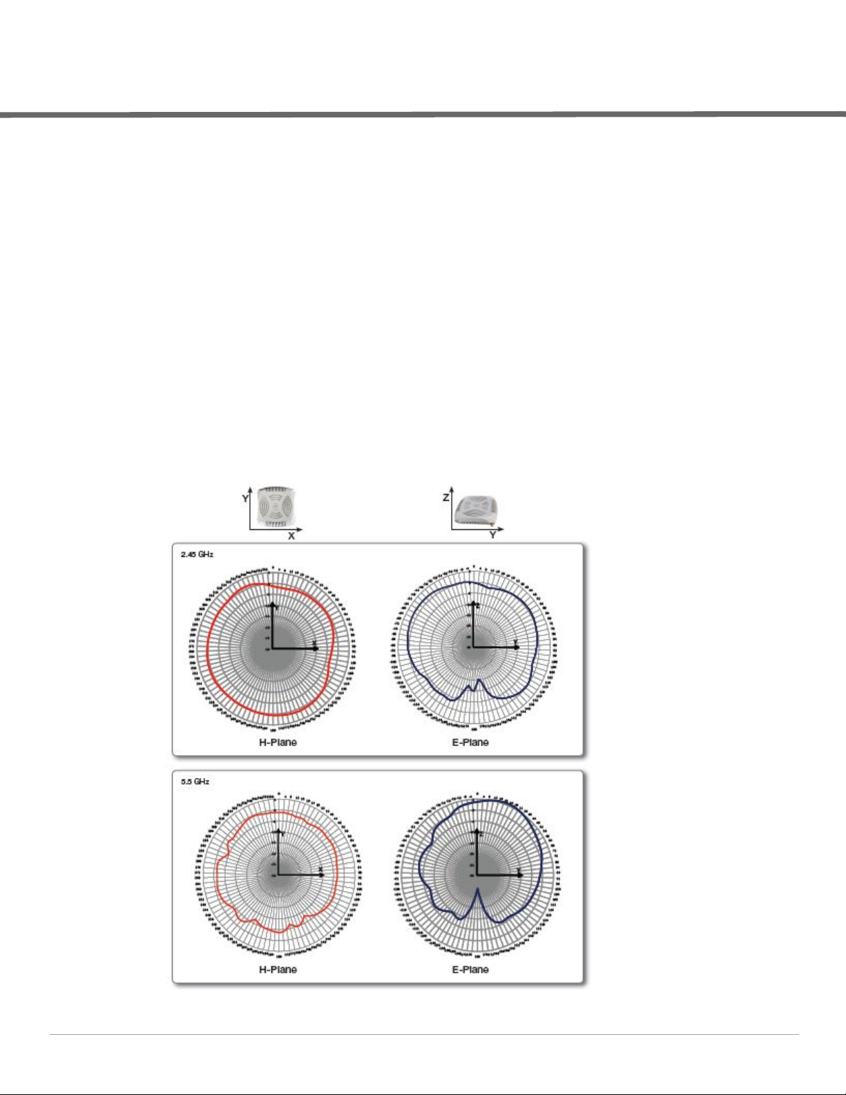
W-IAP92 and W-IAP93 Antenna Patterns
The antenna specifications of W-IAP92 and W-IAP93 are as follows:
W-IAP92: Dual, RP-SMA interfaces for external antenna support (supporting up to 2x2 MIMO with spatial
diversity). For information to configure an external antenna, see “Configuring an External Antenna” on
page63.
W-IAP93: Integrated, omnidirectional antenna elements (supporting up to 2x2 MIMO with spatial diversity)
Maximum antenna gain for W-IAP92 and W-IAP93:
2.4 GHz/2.5 dBi
5 GHz/5.8 dBi
Figure 1 shows antenna patterns of W-IAP93 for 2.45 GHz and 5.5 GHz.
Figure 1 W-IAP93 Antenna Pattern
Dell PowerConnect W-Instant Access Point 5.0.3.0-1.1.0.0 | User Guide W-IAP Internal Antenna Patterns | 15
Page 16
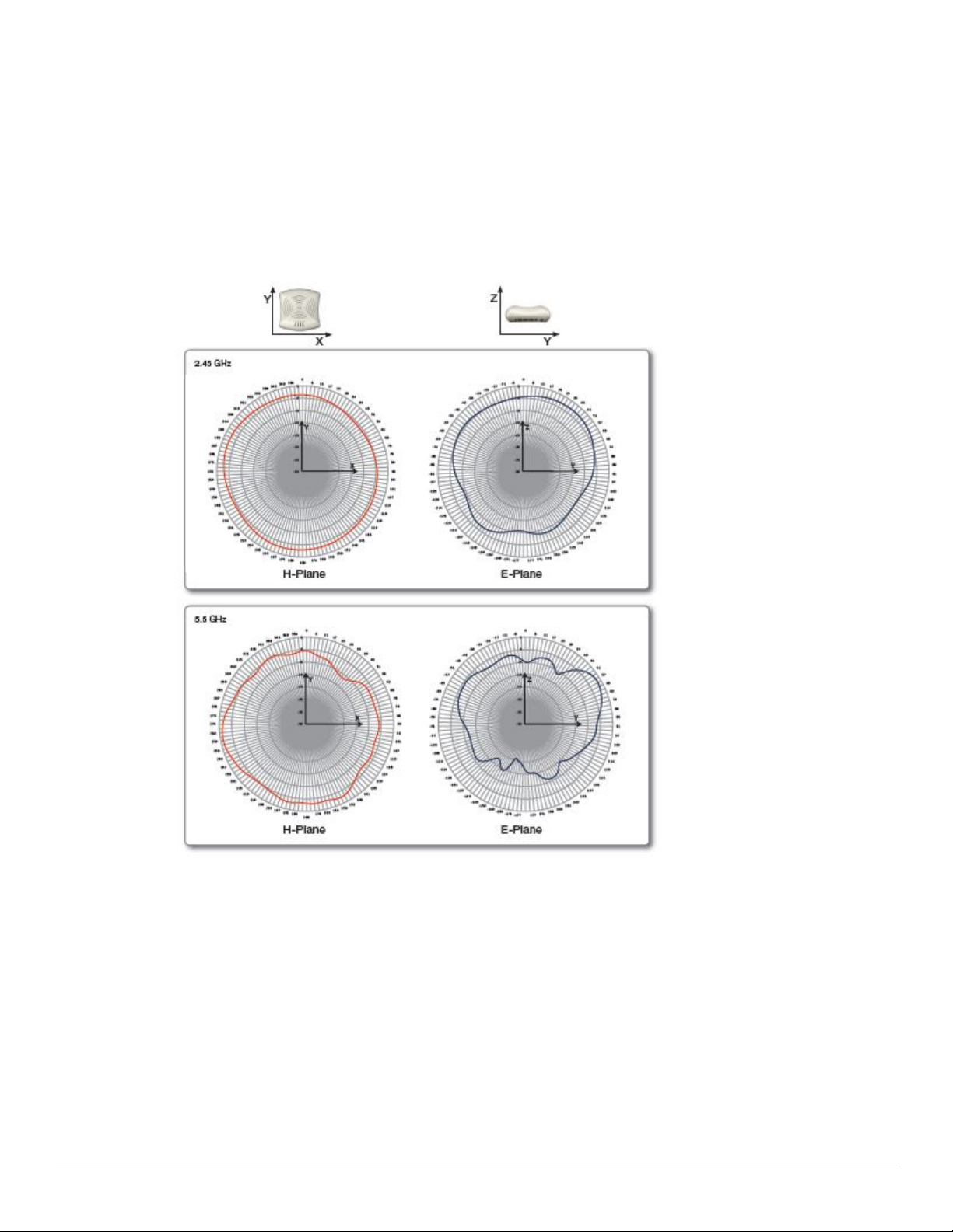
W-IAP105 Antenna Pattern
The antenna specifications of W-IAP105 are as follows:
4 x integrated, omnidirectional antenna elements (supporting up to 2x2 MIMO with spatial diversity)
Maximum antenna gain:
2.4 GHz/2.5 dBi
5.150 GHz to 5.875 GHz/4.0 dBi
Figure 2 shows antenna patterns of W-IAP105 for 2.45 GHz and 5.5 GHz.
Figure 2 W-IAP105 Antenna Pattern
16 | W-IAP Internal Antenna Patterns Dell PowerConnect W-Instant Access Point 5.0.3.0-1.1.0.0 | User Guide
Page 17

Chapter 2
Initial Configuration
This chapter provides information that is required to setup Instant and access the Instant User Interface.
Initial Setup
This section provides a pre-installation checklist and describes the initial procedures required to set up Dell
Instant.
Pre-Installation Checklist
Before installing the Instant Access Point (IAP), make sure that you have the following:
Ethernet cable of required length to connect the IAP to the home router.
One of the following power sources:
IEEE 802.3af-compliant Power over Ethernet (PoE) source. The PoE source can be any power source
equipment (PSE) switch or a midspan PSE device.
Dell power adapter kit (this kit is sold separately).
NOTE: PoE is a method of delivering power on the same physical Ethernet wire that is used for data communication. Power for
devices is provided in one of two ways:
Endspan: The switch that the AP is connected to can provide power.
Midspan: A device can sit between the switch and the AP.
The choice of endspan or midspan depends on the capabilities of the switch that the AP will be connected to. Typically if a switch
is in place and does not support PoE, midspan power injectors are used.
NOTE: A DNS server functions as a phonebook for the Internet and Internet users. It converts human readable computer
hostnames into IP addresses and vice-versa. A DNS server stores several records for a domain name, such as address 'A' record,
name server (NS), and mail exchanger (MX) records. Address 'A' record is the most important record that is stored in a DNS server
because it provides the required IP address for a network peripheral or element.
NOTE: The Dynamic Host Configuration Protocol (DHCP) is an auto-configuration protocol used on IP networks. Computers or any
network peripherals that are connected to IP networks must be configured before they can communicate with other computers on
the network. DHCP allows a computer to be configured automatically, thereby eliminating the need for a network administrator.
DHCP also provides a central database to keep a track of computers connected to the network. This database helps in preventing
any two computers from being configured with the same IP address.
To complete the initial setup, perform the following tasks in the given order:
1. “Connecting the W-IAP to a Power Source” on page18
2. “Assigning an IP Address to the W-IAP” on page18
Dell PowerConnect W-Instant Access Point 5.0.3.0-1.1.0.0 | User Guide Initial Configuration | 17
Page 18

3. “Connecting to the Provisioning Wi-Fi network” on page18
4. “Login into Instant User Interface” on page19
5. “Specifying the Country Code” on page20 Skip this step, if you are installing the W-IAP in United States,
Japan or Israel.
Connecting the W-IAP to a Power Source
Based on the type of the power source that is used, perform one of the following steps to connect the W-IAP to
the power source:
PoE switch - Connect the ENET port of the W-IAP to the appropriate port on the PoE switch.
PoE midspan - Connect the ENET port of W-IAP to the appropriate port on the PoE midspan.
AC to DC power adapter - Connect the 12V DC power jack socket to the AC to DC power adapter.
Assigning an IP Address to the W-IAP
The W-IAP needs an IP address for network connectivity. When you connect the W-IAP to a network, the WIAP receives an IP address from a DHCP server. To get an IP address for an W-IAP, perform the following steps:
1. Connect the ENET port of W-IAP to a switch or router using an Ethernet cable. Ensure that the DHCP
service is enabled on the network.
2. Connect the W-IAP to a power source. The W-IAP will receive an IP address provided by the switch or router.
NOTE: After the IAP starts up, it will try to do DHCP if static IP configuration is not available. If DHCP times out, a default IP within
169.254.x.y/16 subnet will be configured on the IAP. The DHCP client will be still running so that when the DHCP service recovers
the IAP will get a valid IP address and then reboots.
Connecting to the Provisioning Wi-Fi network
Connect a wireless enabled client to the provisioning Wi-Fi network. The provisioning network name is instant.
In the Microsoft Windows operating system, click the wireless network connection icon in the system tray.
The Wireless Network Connection box appears. Click on the instant network and click Connect.
In the MAC operating system, click the AirPort icon. A list of available Wi-Fi networks is displayed. Click on
the instant network.
NOTE: While connecting to the provisioning Wi-Fi network, ensure that the client is not connected to any wired network.
18 | Initial Configuration Dell PowerConnect W-Instant Access Point 5.0.3.0-1.1.0.0 | User Guide
Page 19
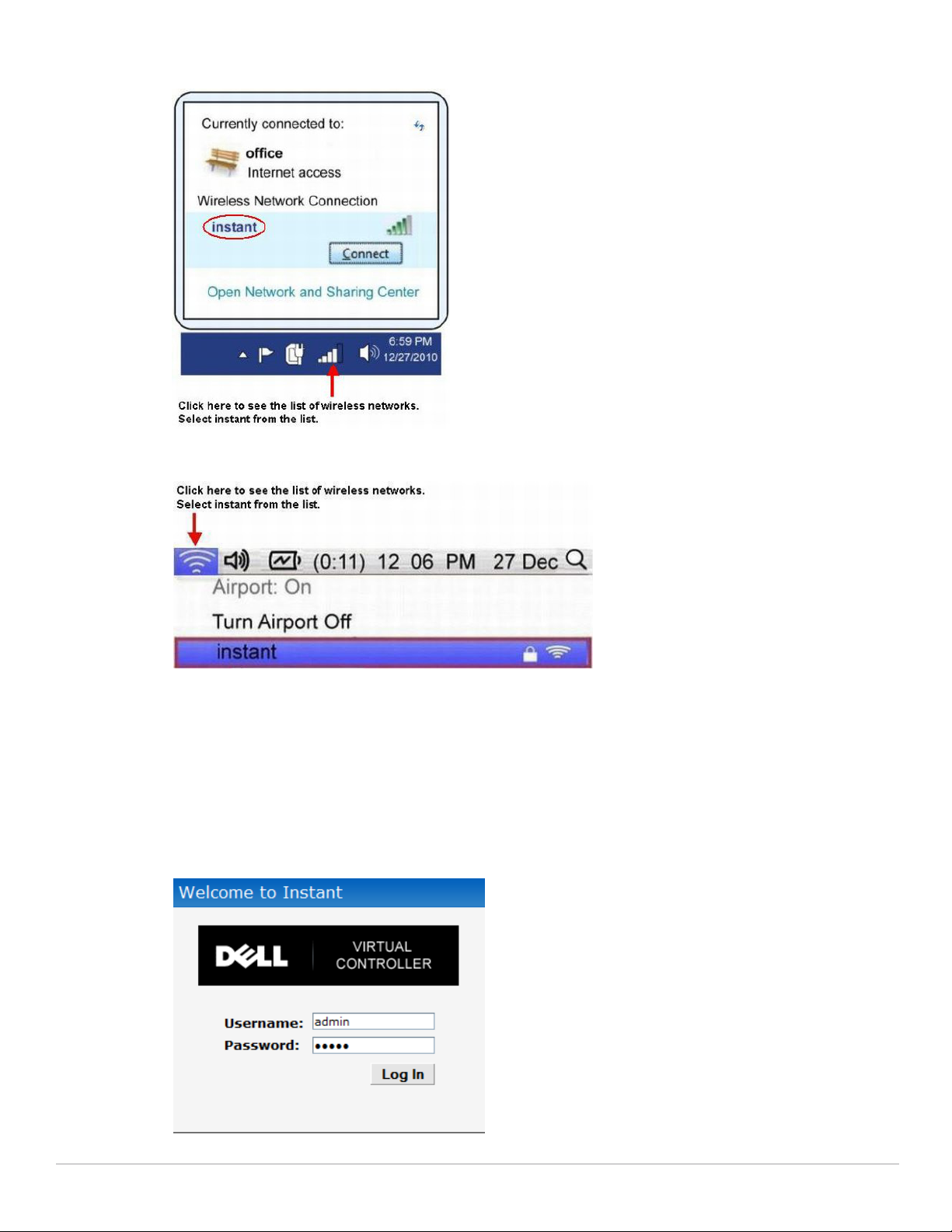
Figure 3 Connecting to Provisioning Wi-Fi network - Microsoft Windows
Figure 4 Connecting to Provisioning Wi-Fi network - MAC OS
Login into Instant User Interface
Open a web browser and enter http://instant.dell-pcw.com in the address field. In the login screen, enter the
following credentials:
Username - admin
Password - admin
Figure 5 Instant User Interface Login Screen
Dell PowerConnect W-Instant Access Point 5.0.3.0-1.1.0.0 | User Guide Initial Configuration | 19
Page 20
When you use the provisioning Wi-Fi network to connect to the internet, all browser requests are directed to the
Instant user interface. For example, if you enter www.example.com in the address field, you will be directed to the
Instant user interface. You can change the default login credentials after your first login.
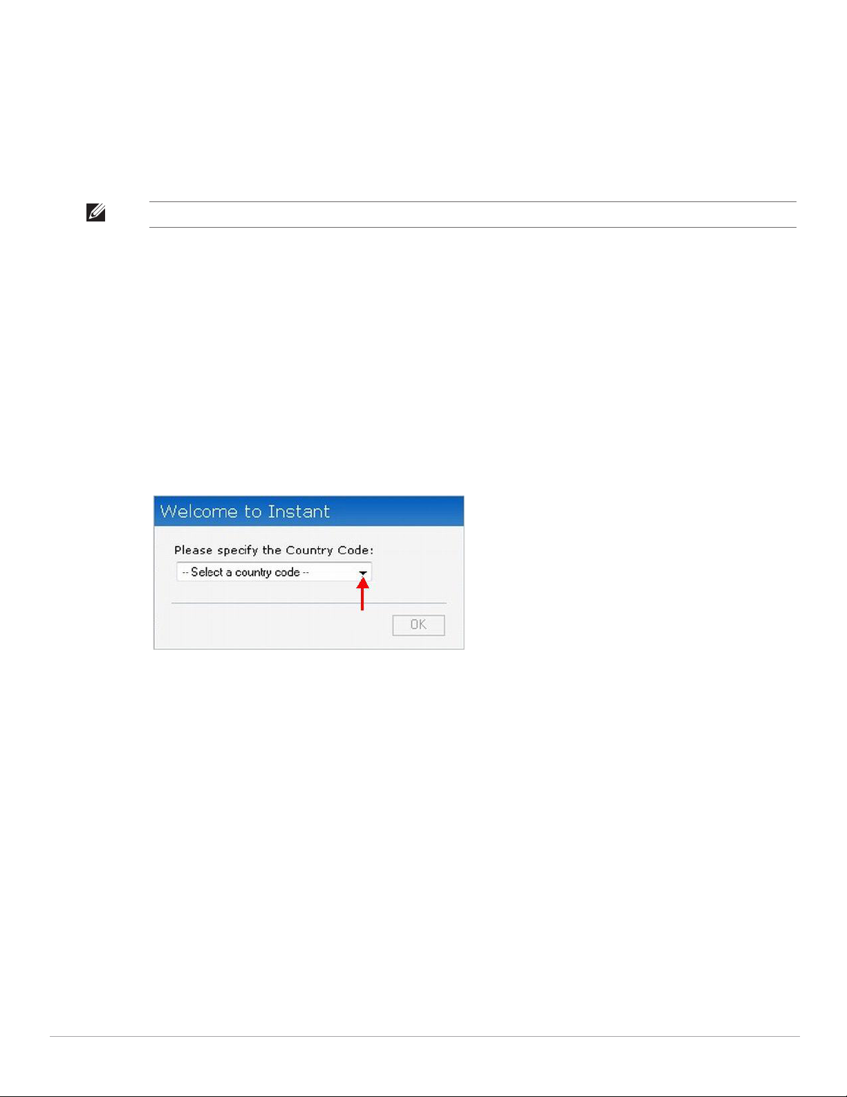
Specifying the Country Code
NOTE: Skip this section, if you are installing the IAP in United States, Japan or Israel.
Dell Instant Access Points are shipped in four variants:
W-IAP - US (United States)
W-IAP - JP (Japan)
W-IAP - IL (Israel)
W-IAP - ROW (Rest of World)
After you successfully login to the Instant user interface, a Country Code box appears if W-IAP-ROW APs are
installed. Select the right country code for the installed W-IAP-ROW APs.
For the complete list of the countries that are supported in the W-IAP-ROW variant type, see “Regulatory
Domain” on page135.
Figure 6 Specifying the Country Code
20 | Initial Configuration Dell PowerConnect W-Instant Access Point 5.0.3.0-1.1.0.0 | User Guide
Page 21
Chapter 3
Instant User Interface
The Instant User Interface (UI) provides a standard web based interface that allows you to configure and monitor
a Wi-Fi network. It is accessible through a standard web browser from a remote management console or
workstation. JavaScript must be enabled on the web browser to view the Instant UI.
Supported browsers are:
Internet Explorer 7 or higher
Safari
Chrome
Mozilla Firefox
NOTE: The Instant UI logs out automatically if the window is unattended for about fifteen minutes.
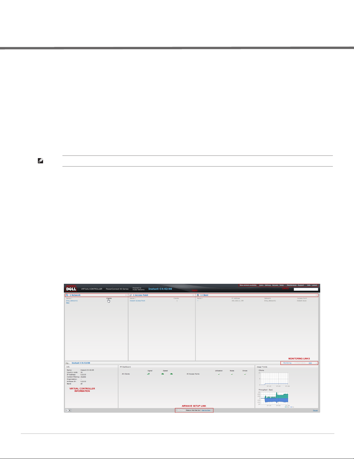
Understanding the Instant UI Layout
The Instant UI consists of the following elements:
Banner
Search
Tabs
Links
Views
These elements are explained in the following sections.
Figure 7 Basic Sections in the Instant UI
Dell PowerConnect W-Instant Access Point 5.0.3.0-1.1.0.0 | User Guide Instant User Interface | 21
Page 22

Banner
The banner is a horizontal grey rectangle that appears at the top left corner of the Instant UI. It displays the
company name, logo, and virtual controller's name.
Search
Administrators can search an IAP, Client or a Network using a simple Search dialog box in the UI. This Search
option helps fill in the blank when you type in a word and suggested matches will be automatically displayed in a
dynamic list. The list will become more relevant and detailed when more number of keywords are typed in. This is
similar to the auto-complete feature of Google Search.
Tabs
The Instant UI consists of the following tabs:
Networks - Provides information about the Wi-Fi networks in the Dell Instant network.
Access Points - Provides information about the IAPs in the Instant network.
Clients - Provides information about the clients in the Instant network.
Each tab appears in a compressed view by default. A number, specifying the number of networks, IAPs, or clients
in the network precedes the tab names. Click on the tabs to see the expanded view and click to compress the
expanded view. Items in each tab are associated with a triangle icon. Click to sort the data in increasing or
decreasing order. Each tab is explained in the following sections.
Networks Tab
This tab displays a list of Wi-Fi networks that are configured in the Dell Instant network. The network names
appear as links. The expanded view displays the following information about each Wi-Fi network:
Name - Name of the network.
Clients - Number of clients that are connected to the network.
Type - Network type: Employee, Guest, or Voice.
Band - Band in which the network is broadcast: 2.4 GHz band, 5.4 GHz band, or both.
Authentication Method - Authentication method required to connect to the network.
Key Management - Authentication key type.
IP Assignment - Source of IP address for the client.
To add a Wi-Fi network, click the New link in the Networks tab. For more information about a wireless network
and the procedure to add a wireless network, see Chapter 4, “Wireless Network” on page35.
An edit link appears on clicking the network name in the Networks tab. For information about editing a wireless
network, see “Editing a Network” on page47. To delete a network, click x on the right side of the edit link.
Figure 8 Networks Tab - Compressed View and Expanded View
22 | Instant User Interface Dell PowerConnect W-Instant Access Point 5.0.3.0-1.1.0.0 | User Guide
Page 23
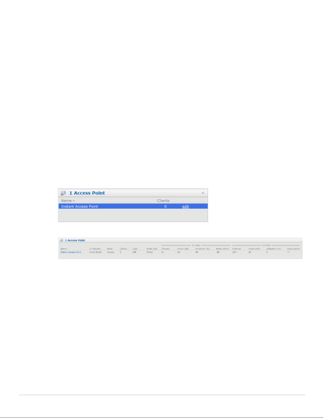
Access Points Tab
If the Auto Join Mode feature is enabled, a list of enabled and active IAPs in the Dell Instant network is displayed
in the Access Points tab. The IAP names are displayed as links.
If the Auto Join Mode feature is disabled, then a New link appears. Click this link to add a new IAP to the
network. Also, if an IAP is configured and not active, its MAC Address is displayed in red.
The expanded view displays the following information about each IAP:
Name - Name of the access point.
IP Address - IP address of the IAP.
Mode - Mode of the IAP.
Clients - Number of clients that are connected to the IAP.
Type - Model number of the IAP.
Mesh Role - Role of the mesh IAP
Channel - Channel the IAP is currently broadcasting on.
Power (dB) - Maximum transmit EIRP of the radio.
Utilization (%) - Utilization percentage of the IAP radios.
Noise (dBM) - Noise floor of IAP.
An edit link appears on clicking the IAP name. For details about editing IAP settings see, “Editing W-IAP
Settings” on page56.
Figure 9 Access Points Tab - Compressed View and Expanded View
Clients Tab
This tab displays a list of clients that are connected to the Dell Instant network. The client names appear as links.
The expanded view displays the following information about each client:
Name - Name of the client.
IP Address - IP address of the client.
MAC Address - MAC address of the client.
OS - Operating system that the client is running on.
Network - Network that the client is connected to.
Access Point - IAP to which the client is connected.
Channel - Channel that the client is currently broadcasting on.
Type - Wi-Fi type of the client: A, G, AN, or GN.
Role - Role assigned to the client.
Signal - Signal strength.
Speed (mbps) - Data transfer speed.
Dell PowerConnect W-Instant Access Point 5.0.3.0-1.1.0.0 | User Guide Instant User Interface | 23
Page 24

Figure 10 Client Tab - Compressed View and Expanded View
Links
The following links allow you to configure the features and settings for the Instant network. Each of these links is
explained in the subsequent sections.
New version available
Users
Settings
Servers
Roles
Servers
Support
Help
Logout
Monitoring
Client Alerts
IDS
Language
AirWave Setup
Pause/Resume
New version available
This link appears in the Instant UI only if a new image version is available on the image server and AirWave is not
configured. For more information about the New version available link and its functions, see “Firmware Image
Server in Cloud Network” on page61.
Users
This link displays the Users box. This box contains fields that are required to add, edit, or delete a user or users.
You can also specify the user type. Two types of users, employee and guest, will be using the Dell Instant network.
For more information about users, see Chapter 21, “User Database” .
24 | Instant User Interface Dell PowerConnect W-Instant Access Point 5.0.3.0-1.1.0.0 | User Guide
Page 25
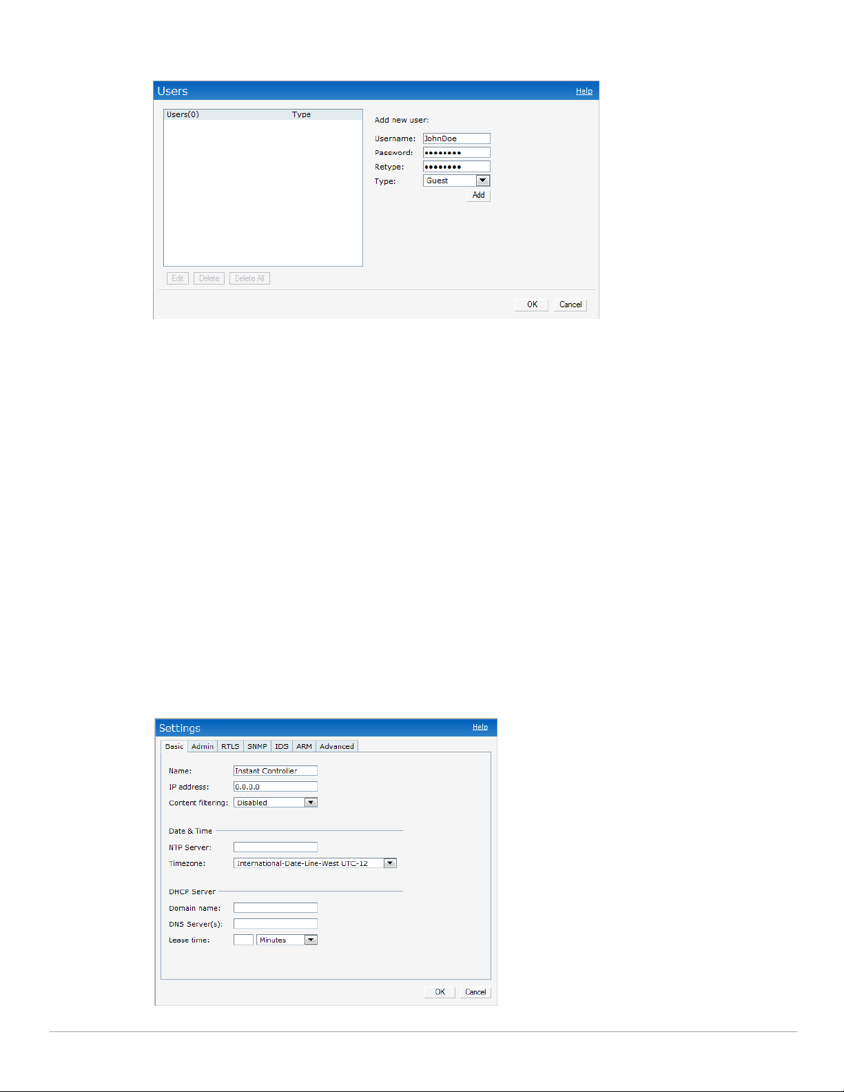
Figure 11 Users Box
Settings
This link displays the Settings box. The Settings box consists of the following tabs:
Basic - View or edit the virtual controller's name, IP address, and Content filtering setting. For information
about virtual controller settings and content filtering, see Chapter 8, “Virtual Controller” and Chapter 13,
“Content Filtering” .
Admin - View or edit the admin credentials.
RTLS - View or edit the RTLS server settings.
SNMP - View or specify SNMP agent settings. For information see Chapter 17, “SNMP” .
IDS - View or select the Rogue AP classification and Containment methods to monitor the network for the
presence of unauthorized IAPs and clients. For more information see Chapter 16, “Intrusion Detection
System” .
ARM -View or assign channel and power settings for all the IAPs in the network. For information about ARM,
see Chapter 15, “Adaptive Radio Management” .
Advanced - View or edit the preferred band for the network, dynamic RADIUS Proxy, and Auto join mode
settings. For information about dynamic RADIUS Proxy and Auto join mode, see “External RADIUS Server”
on page70 and “Auto Join Mode” on page53.
Figure 12 Settings Link - Default View
Dell PowerConnect W-Instant Access Point 5.0.3.0-1.1.0.0 | User Guide Instant User Interface | 25
Page 26
Servers
This link displays the RADIUS Server box. This box allows you to add new server. To add a new radius server, see
“Configuring an External RADIUS Server” on page70.
Roles
This link displays the Roles box. You can create new user roles and new rules for the user roles. For more
information, see “User Roles” on page85.
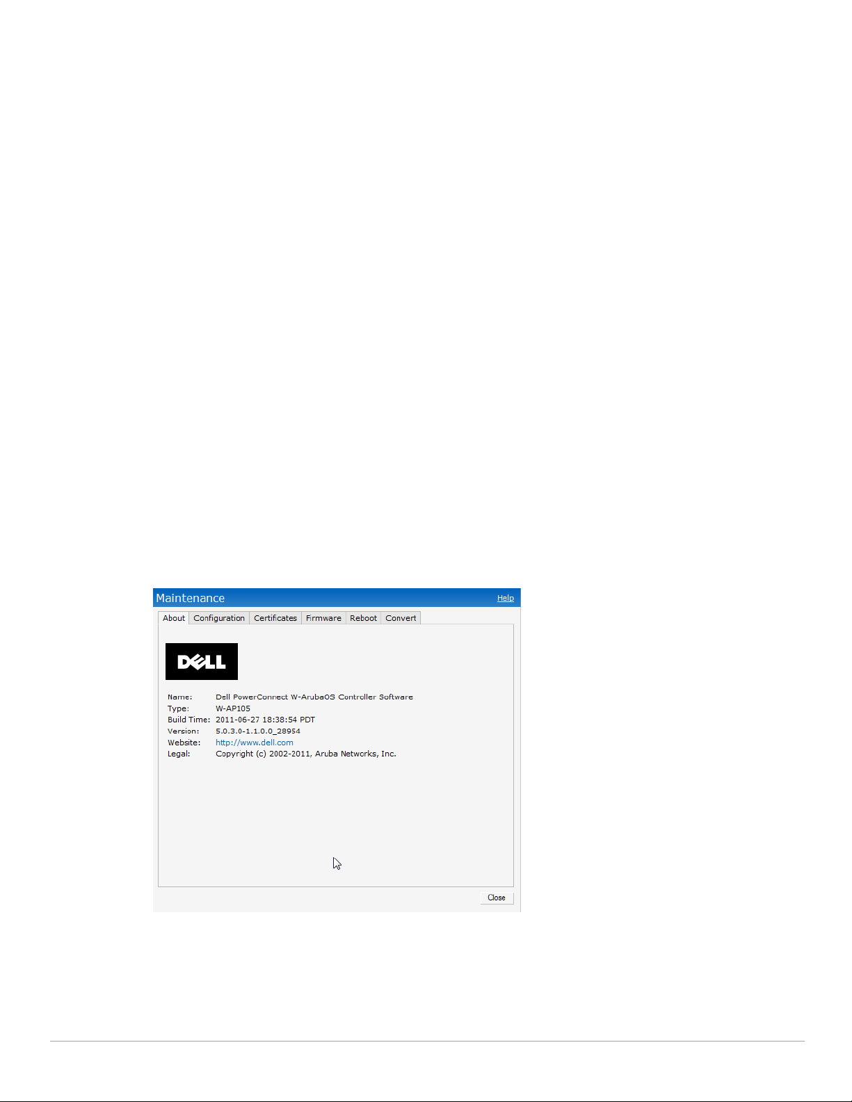
Maintenance
This link displays the Maintenance box. The Maintenance box allows you to maintain the Wi-Fi network. It
consists of the following tabs:
About - Displays the Build Time, IAP model name, Dell OS version, Dell website homepage, and Copyright
information.
Configuration - Displays the current configuration of the network. The Clear Configuration button allows
you to delete or clear the current configuration of the network and reset to provisioning configuration.
Certificates - Displays information about current certificate installed in the network. Provides interface to
upload new certificates and to set passphrase for the certificates. For more information, see “Certificates” on
page82.
Firmware - Displays the current firmware version and provides options to upgrade to a new firmware version.
For more information, see“Manual Firmware Image Check and Upgrade” on page63.
Reboot - Displays the IAPs in the network and provides an option to reboot the required access point or all
access points. For more information, see “Rebooting the W-IAP” on page61.
Convert - Provides an option to change the virtual controller managed network to an Dell Mobility Controller
managed network. For more information, see “Migrating from a Virtual Controller Managed Network to
Mobility Controller Managed Network” on page59.
Figure 13 Maintenance Link - Default View
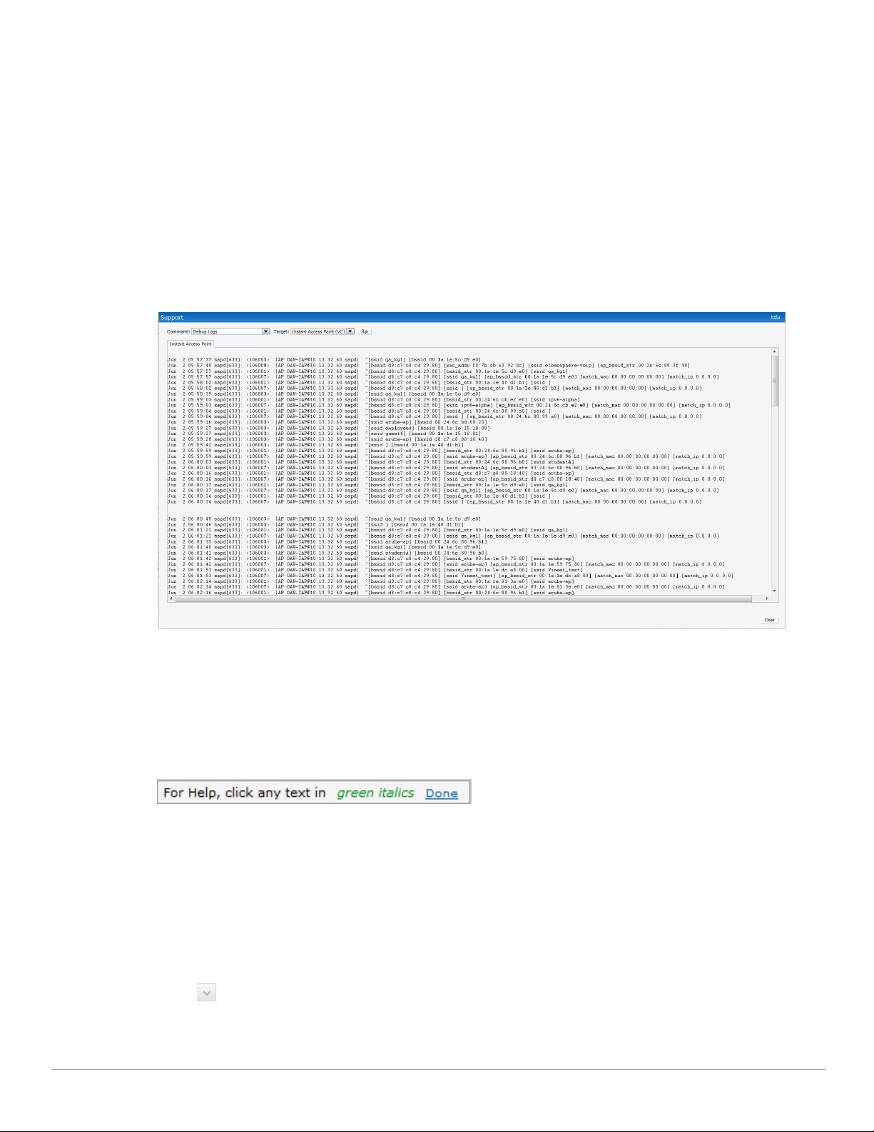
Support
This link displays the Support box. The Support box consists of following:
Command drop-down list - Provides various options for which you can generate support logs.
Target drop-down list - Provides a list of IAPs in the network.
26 | Instant User Interface Dell PowerConnect W-Instant Access Point 5.0.3.0-1.1.0.0 | User Guide
Page 27

Run button - Click this button to generate the support log for the selected option and IAP.
Access point tabs - Displays support log for the selected IAPs.
To view the logs and information, perform the following steps:
1. At the top right corner of Instant UI, click the Support link. The Support box appears.
2. Select the required option from the Command drop-down list. For example, Active Configuration.
3. Select all IAPs or required IAP from the Target drop-down list for which you want to view the Active
configuration.
4. Click Run.
NOTE: For more information, use the support commands under the supervision of Dell technical support.
You can view the following information for each access point in the Dell Instant network using the support box:
AP Summary - Displays the IAP configuration.
Debug Logs - Displays debug logs of the selected IAP.
Driver Logs - Displays the driver logs of the selected IAP.
Tech Support Dump - Displays the technical support dump logs of the selected IAP.
Active Configuration - Displays the active configuration of virtual controller.
Saved Configuration - Displays the saved configuration of virtual controller.
AP Management Frames - Displays the traced 802.11 management frames of the selected IAP.
AP Authentication Frames - Displays the authentication trace buffer information of the selected IAP.
AP System Status - Displays detailed system status information for the selected IAP.
AP Crash Info - Displays crash log information (if it exists) for the selected IAP. The stored information is
cleared from the flash after the AP reboots.
AP 802.1X Statistics - Displays the 802.1X statistics of the selected IAP.
AP RADIUS Statistics - Displays the RADIUS statistics of the selected IAP.
AP System Status - Displays the system status of the selected IAP.
AP Client Table - Displays information of the client connected to the selected IAP.
AP Association Table - Displays information of the selected IAP association.
AP Allowed Channels - Displays information of the allowed channels for the selected IAP.
AP Radio 0 Stats - Displays aggregate debug statistics of the selected IAP Radio 0.
AP Radio 1 Stats - Displays aggregate debug statistics of the selected IAP Radio 1.
Bridge Table - Displays bridge table entry statistics including MAC address, VLAN, assigned VLAN,
Destination and flag information for the selected IAP.
User Table - Displays datapath user statistics such as current entries, pending deletes, high water mark,
maximum entries, total entries, allocation failures, invalid users, and maximum link length for the selected
IAP.
Session Table - Displays the datapath session table statistics for the selected IAP.
Route Table - Displays datapath route table statistics for the selected IAP.
Datapath Statistics - Displays the hardware packet statistics for the selected IAP.
VLAN Table - Displays the VLAN table information such as VLAN memberships inside the datapath
including L2 tunnels for the selected IAP.
BSSID Table - Displays the Basic Service Set (BSS) table of the selected IAP.
Dell PowerConnect W-Instant Access Point 5.0.3.0-1.1.0.0 | User Guide Instant User Interface | 27
Page 28
IDS Status - Displays WLAN Interface, Data Structures, WLAN Interface Switch Status and RTLS
Configuration tables for the selected IAP.
IDS AP Table - Displays the Monitored IAP Table, which lists all the IAPs monitored by the selected IAP.
ARM Bandwidth Management - Displays bandwidth management information for the selected IAP.
ARM History - Displays the history of channel and power changes due to Adaptive Radio Management
(ARM) for the selected IAP.
ARM Neighbors - Displays the ARM settings for the selected IAP's neighbors.
ARM RF Summary - Displays the state and statistics for all channels being monitored by the selected IAP.
ARM Scan Times - Displays AM channel scan times for the selected IAP.
Use this command under the supervision of Dell technical support to help debug process errors.
Figure 14 Support Box
Help
The Help link at the top right corner of the Instant UI allows you to view a short description or definition of
selected terms and fields in the Instant UI. To activate the context-sensitive help, perform the following steps:
1. At the top right corner of Instant UI, click the Help link. The following box appears below the Help link.
Figure 15 Help Link
2. Click any text or term displayed in green italic to view its description or definition.
3. To disable the help mode, click the Done button.
Logout
Use this link to logout of the Instant UI.
Monitoring
This link displays the Monitoring pane. This pane can be used to monitor the Dell Instant network. Use the down
arrow located to the right side of these links to compress or expand the monitoring pane. The monitoring
pane consists of the following sections:
Info
28 | Instant User Interface Dell PowerConnect W-Instant Access Point 5.0.3.0-1.1.0.0 | User Guide
Page 29
RF Dashboard
Usage Trends
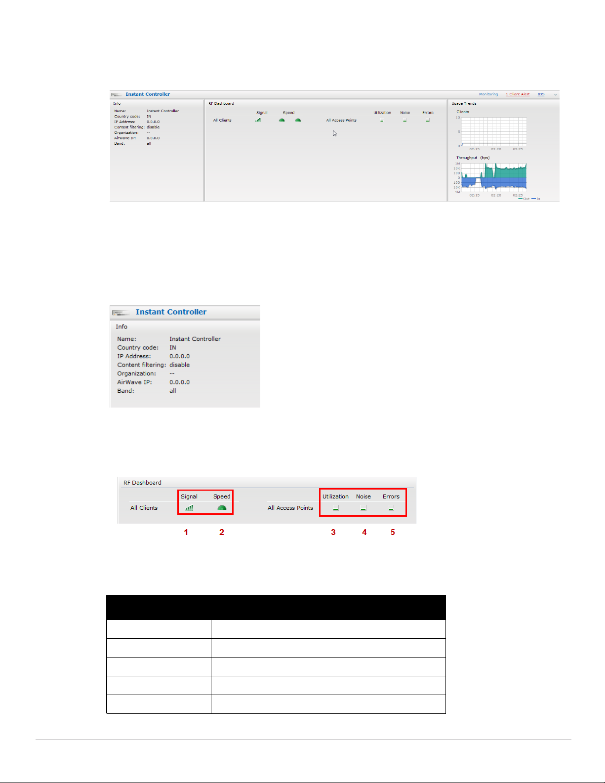
Figure 16 Monitoring on Instant UI
Info
Displays the configuration information of the virtual controller by default. In a Network View, this section
displays configuration information of the selected network. Similarly, in an Instant Access Point View or Client
View, this section displays the configuration information of the selected IAP or the client.
Figure 17 Info Section in the Monitoring Pane
RF Dashboard
Allows you to view trouble spots in the network. It displays the following information:
Figure 18 RF Dashboard in the Monitoring Pane
The following table lists the icons in the RF Dashboard.
Table 3 RF Dashboard Icons
Icon Name
1 Signal bar
2 Speed icon
3 Utilization icon
4 Noise icon
5 Errors icon
Dell PowerConnect W-Instant Access Point 5.0.3.0-1.1.0.0 | User Guide Instant User Interface | 29
Page 30

Clients - Lists the clients with low speed or signal strength in the network.
Signal - Displays the signal strength of the client. Depending on the signal strength of the client, the color
of the lines on the Signal bar changes from Green > Orange > Red.
Green - Signal strength is more than 20 decibels.
Orange - Signal strength is between 15 - 20 decibels.
Red - Signal strength is less than 15 decibels.
To view the signal graph for a client, click on the signal bar against the client in the Signal column.
Speed - Displays the data transfer speed of the client. Depending on the data transfer speed of the client,
the color of the Signal bar changes from Green > Orange > Red.
Green - Data transfer speed is more than 50 percent of the maximum speed supported by the
client.
Orange - Data transfer speed is between 25 - 50 percent of the maximum speed supported by the
client.
Red - Data transfer speed is less than 25 percent of the maximum speed supported by the client.
To view the data transfer speed graph of a client, click on the speed icon against the client in the Speed column.
Access Points - Lists the IAPs whose utilization, noise, or errors are not within the specified threshold. The
IAP names appear as links. When the IAP is clicked, the IAP configuration information is displayed in the Info
section. The RF Dashboard section is pushed to the bottom left corner of the Instant UI. The RF Trends
section appears in its place. This section consists of the Utilization, Band frames, Noise Floor, and Errors
graphs. For more information on the graphs, see Chapter 19, “Monitoring” .
Utilization - Displays the radio utilization rate of the IAPs. Depending on the percentage of utilization,
the color of the lines on the Utilization icon changes from Green > Orange > Red.
Green - Utilization is less than 50 percent.
Orange - Utilization is between 50 - 75 percent.
Red - Utilization is more than 75 percent.
To view the utilization graph of an IAP, click on the Utilization icon against the IAP in the Utilization column.
Noise - Displays the noise floor of the IAPs. Noise is measured in decibels/meter. Depending on the noise
floor, the color of the lines on the Noise icon changes from Green > Orange > Red.
Green - Noise floor is more than 87dBm.
Orange - Noise floor is between 80 dBm - 87 dBm.
Red - Noise floor is less than 80 dBm.
To view the noise floor graph of an IAP, click on the noise icon against the IAP in the Noise column.
Errors - Displays the errors for the IAPs. Depending on the errors, color of the lines on the Errors icon
changes from Green > Yellow > Red.
Green - Errors are less than 5000 frames per second.
Orange - Errors are between 5000 - 10000 frames per second.
Red - Errors are more than 10000 frames per second.
To view the errors graph of an IAP, click on the Errors icon against the IAP in the Errors column.
Usage Trends
Displays the following graphs:
Clients - In the default Virtual Controller view, the Clients graph displays the number of clients that were
associated with the virtual controller for the last 15 minutes. In Network or IAP view, this graph displays
the number of clients that were associated with the selected network or IAP for the last 15 minutes.
30 | Instant User Interface Dell PowerConnect W-Instant Access Point 5.0.3.0-1.1.0.0 | User Guide
Page 31

Throughput - In the default Virtual Controller view, the Throughput graph displays the incoming and
outgoing throughput traffic for the virtual controller for the last 15 minutes. In Network or IAP view, this
graph displays the incoming and outgoing throughput traffic for the selected network or IAP for the last 15
minutes.
Figure 19 Usage Trends Section in the Monitoring Pane
For more information about the graphs and monitoring procedures, see Chapter 19, “Monitoring” .
Client Alerts
Alerts are generated when a user faces problems while accessing or connecting to the Wi-Fi network. The Client
Alerts link appears in red only if there are any client alerts. Click this link to see the related alert. An alert consists
of the following fields:
Timestamp - Displays the time at which the client alert was recorded.
MAC address - Displays the MAC address of the client.
Description - Provides a short description of the error or alert.
Details - Provides a detailed description of the error or alert.
NOTE: New alerts will be generated for an incomplete DHCP transaction of a client.
Figure 20 Client Alerts link on Instant UI
Dell PowerConnect W-Instant Access Point 5.0.3.0-1.1.0.0 | User Guide Instant User Interface | 31
Page 32

Figure 21 Client Alerts Link
For more information about alerts, see Chapter 20, “Alert Types and Management” .
IDS
This link displays a list of foreign APs and foreign clients that are detected in the network. It consists of the
following sections:
Foreign Access Points Detected - Lists the APs that are not controlled by the virtual controller. The following
information is displayed for each foreign AP:
MAC address - Displays the MAC address of the foreign AP.
Network - Displays the name of the network to which the foreign AP is connected.
Classification - Displays the classification of the foreign AP - Interfering IAP or Rogue IAP.
Channel - Displays the channel in which the foreign AP is operating.
Type - Displays the Wi-Fi type of the foreign AP.
Last seen - Displays the time when the foreign AP was last detected in the network.
Where - Provides information about the IAP that detected the foreign AP. Click the pushpin icon to view
the information.
Foreign Clients Detected - Lists the clients that are not controlled by the virtual controller. The following
information is displayed for each foreign client:
MAC address - Displays the MAC address of the foreign client.
Network - Displays the name of the network to which the foreign client is connected.
Classification - Displays the classification of the foreign client - Interfering client.
Channel - Displays the channel in which the foreign client is operating.
Type - Displays the Wi-Fi type of the foreign client.
Last seen - Displays the time when the foreign client was last detected in the network.
Where - Provides information about the IAP that detected the foreign client. Click the pushpin icon to
view the information.
For more information on the intrusion detection feature, see Chapter 16, “Intrusion Detection System” .
Figure 22 Intrusion Detection on Instant UI
32 | Instant User Interface Dell PowerConnect W-Instant Access Point 5.0.3.0-1.1.0.0 | User Guide
Page 33

Language
The language links are provided in the login screen to allow users to select the preferred language before logging
in to the Instant UI. These links are located at the bottom left corner of the Instant UI. A default language is
selected based on the language preferences in the client desktop operating system or browser. If Dell Instant
cannot detect the language, then English (En) is used as the default language.
AirWave Setup
AirWave is a solution for managing rapidly changing wireless networks. When enabled, AirWave allows you to
manage the Instant network. For more information on AirWave, see Chapter 18, “Airwave Integration and
Management” . The AirWave status is displayed on the right side of the language links in the Instant UI. If the
AirWave status is Not Set Up, click the Set Up Now link to set up the AirWave. The Settings box appears with
Admin tab selected. For information to configure AirWave, see “Configuring AirWave” on page114.
Figure 23 AirWave Setup Link – AirWave Configuration
Pause/Resume
The Pause/Resume link is located at the bottom right corner of the Instant UI. The Instant UI is automatically
refreshed after every 15 seconds by default.
Click the Pause link to pause the automatic refreshing of the Instant UI. When the automatic Instant UI
refreshing is paused, the Pause link changes to Resume. Click the Resume link to resume automatic refreshing.
The Pause link is useful when you want to analyze or monitor the network or a network element and therefore do
not want the user interface to refresh. Automatic refreshing allows you to get the latest information about the
network and network elements.
Views
Depending on the link or tab that is clicked, the Instant UI displays information about the virtual controller, WiFi networks, IAPs, or the clients in the Info section. The views on the Instant UI are classified as follows:
Virtual Controller view - The Virtual Controller view is the default view. This view allows you to monitor the
Dell Instant network.
Network view - The Network view provides information that is necessary to monitor a selected wireless
network. All Wi-Fi networks in the Dell Instant network are listed in the Networks tab. Click the name of the
network that you want to monitor. Network view for the selected network appears.
Dell PowerConnect W-Instant Access Point 5.0.3.0-1.1.0.0 | User Guide Instant User Interface | 33
Page 34

Instant Access Point view - The Instant Access Point view provides information that is necessary to monitor a
selected IAP. All IAPs in the Dell Instant network are listed in the Access Points tab. Click the name of the
IAP that you want to monitor. Access Point view for that IAP appears.
Client view - The Client view provides information that is necessary to monitor a selected client. In the
Virtual Controller view, all clients in the Dell Instant network are listed in the Clients tab. Click the IP
address of the client that you want to monitor. Client view for that client appears.
For more information on the graphs and the views, see Chapter 19, “Monitoring” .
34 | Instant User Interface Dell PowerConnect W-Instant Access Point 5.0.3.0-1.1.0.0 | User Guide
Page 35

Chapter 4
Wireless Network
In a Wireless LAN (WLAN), laptops, desktops, PDAs, and other computer peripherals are connected to each
other without any network cables. These network elements or clients use radio signals to communicate with each
other. Wireless networks are set up based on the IEEE 802.11 standards. The IEEE 802.11 is a set of standards
that are categorized based on the radio wave frequency and the data transfer rate. For more information about
the IEEE 802.11 standards, see Table 4.
Table 4 IEEE 802.11 Standards
IEEE Network Standard Frequency Used (in GHz)
802.11a 5.0 54
802.11b 2.4 11
802.11g 2.4 54
802.11n 2.4 or 5.0 300
During start up, a wireless client searches for radio signals or beacon frames that originate from the nearest IAP.
After locating the IAP, the following transactions take place between the client and the IAP:
1. Authentication - The IAP communicates with a RADIUS server to validate or authenticate the client.
2. Connection - After successful authentication, the client establishes a connection with the IAP.
Maximum Data Transfer Rate
(in Mbps)
Network Types
Dell Instant wireless networks are categorized as:
Employee Network
Voice Network
Guest Network
Employee Network
An Employee network is a classic Wi-Fi network. This network type is supported with full customization on Dell
Instant. It will be used by the employees in the organization. Passphrase based or 802.1X based authentication
methods are supported on this network type. Employees can access the protected data of an enterprise through
the employee network after successful authentication.
Adding an Employee Network
This section provides the procedure to add an employee network.
1. In the Networks tab, click the New link. The New Network box appears.
Dell PowerConnect W-Instant Access Point 5.0.3.0-1.1.0.0 | User Guide Wireless Network | 35
Page 36

Figure 24 Adding an Employee Network - Basic Info Tab
2. In the Basic Info tab, perform the following steps:
a. Type a name for the network in the Name (SSID) text box.
b. Select the Employee radio button (this is selected by default) from the Primary usage options. This
selection determines the primary usage of the network being added.
c. Select the required Client IP assignment option. Available options for an Employee network are Network
assigned - Default, Network assigned - VLAN ID, and Virtual Controller assigned.
Table 5 Conditions for Adding an Employee Network- Basic Info Tab
If then,
You select the Network assigned - Default option The client gets the IP address in the same subnet at the IAPs.
You select the Network assigned – VLAN ID option The client gets the IP address from the specified VLAN. Enter the ID
You select Virtual Controller assigned option The client gets the IP address from the virtual controller. The virtual
3. Click the More link and perform the following steps (These steps are optional).
a. Band - Set the band at which the wireless network will transmit radio signals. Available options are All, 2.4
GHz, and 5 GHz. The All option is selected by default. It is also the recommended option.
b. Hide SSID - Select this check box if you want to hide the SSID (network name) from the users.
of the VLAN in the VLAN ID text box.
controller creates a private subnet and VLAN on the IAP’s for the
wireless clients. The virtual controller NATs all traffic that passes out
of this interface. This setup eliminates the need for complex VLAN
and IP address management for a multi-site wireless network.
36 | Wireless Network Dell PowerConnect W-Instant Access Point 5.0.3.0-1.1.0.0 | User Guide
Page 37

Figure 25 Band and Hide SSID Settings
4. Click Next and set appropriate security levels using the slider button in the Security tab. Default selection is
Personal. Available options are Enterprise, Personal, and Open.
Table 6 Conditions for Adding an Employee Network - Security Tab
If then,
You select the Enterprise security level Perform the following steps:
1. Select the required key options from the Key management dropdown list. Available options are:
WPA-2 Enterprise
WPA Enterprise
Both (WPA-2 & WPA)
Dynamic WEP with 802.1x
2. Select the required Authentication server option from the
Authentication server 1drop-down list. Available options are:
External - If you select this option, then an external radius server
has to be configured to authenticate the users. For information
on configuring an external RADIUS server, see Chapter 9,
“Authentication” .
Internal Server- If you select this option, then users who are
required to authenticate with the internal RADIUS server must
be added. Click the Users link to add the users.
For information on adding a user, see “Adding a User” on page 133.
Dell PowerConnect W-Instant Access Point 5.0.3.0-1.1.0.0 | User Guide Wireless Network | 37
Page 38

Table 6 Conditions for Adding an Employee Network - Security Tab (Continued)
If then,
You want to use the default security level, Personal Perform the following steps:
1. Select the required key options from the Key management dropdown list. Available options are:
WPA-2 Personal
WPA Personal
Both (WPA-2 & WPA)
Static WEP
If you have selected Static WEP, then do the following:
Select appropriate WEP key size from the WEP key size drop-
down list. Available options are 64-bit and 128-bit.
Select appropriate Tx key from the Tx Key dropdown list.
Available options are 1, 2, 3,and 4.
Enter an appropriate WEP key and reconfirm.
2. Select a passphrase format from the Passphrase format dropdown list. Available options are:
8-63 alphanumeric chars
64 hexadecimal chars
3. Enter a passphrase in the Passphrase text box and reconfirm.
4. Select the required option from the MAC authentication dropdown list. Available options are
None - This option provides open authentication. Any client that
requests association is allowed to connect to the network. Open
authentication is not recommended unless you want users to
gain quick access to the network.
External RADIUS Server - If you select this option, then an external
radius server has to be configured to authenticate the users. For
information on configuring external RADIUS server, see “Configuring
an External RADIUS Server” on page 70.
You select the Open security level Select the required MAC authentication from the MAC
authentication drop-down list. Available options are:
None -This option provides open authentication. Any client that
requests association is allowed to connect to the network. Open
authentication is not recommended unless you want users to
gain quick access to the network.
External RADIUS Server - If you select this option, then an
external radius server has to be configured to authenticate the
users. For information on configuring an external RADIUS
server, see “Configuring an External RADIUS Server” on
page 70.
38 | Wireless Network Dell PowerConnect W-Instant Access Point 5.0.3.0-1.1.0.0 | User Guide
Page 39

Figure 26 Security Tab - Enterprise
Dell PowerConnect W-Instant Access Point 5.0.3.0-1.1.0.0 | User Guide Wireless Network | 39
Page 40

Figure 27 Security Tab - Personal
Figure 28 Security Tab - Open
40 | Wireless Network Dell PowerConnect W-Instant Access Point 5.0.3.0-1.1.0.0 | User Guide
Page 41

5. Click Next. The Access tab appears. The Allow any to all destinations access rule is enabled by default. This
rule allows traffic to all destinations. Instant Firewall treats packets based on the first rule matched. For more
information, see Chapter 12, “Instant Firewall” .
To edit the default rule, perform the following steps:
a. Select the rule and click the Edit button.
b. Select appropriate options in the Edit Rule box and click OK.
To define an access rule, perform the following steps:
a. Click the New button.
b. Select appropriate options in the New Rule box.
c. Click OK.
Figure 29 Adding an Employee Network - Access Rules Tab - Network
6. Click Finish. The network is added and listed in the Networks tab.
Voice Network
Use the Voice network type when you want devices that provide only voice services like handsets or only
applications that require voice-like prioritization need connectivity.
Adding a Voice Network
This section provides the procedure to add a voice network.
1. In the Networks tab, click the New link. The New Network box appears.
Dell PowerConnect W-Instant Access Point 5.0.3.0-1.1.0.0 | User Guide Wireless Network | 41
Page 42

Figure 30 Adding a Voice Network - Basic Info Tab
In the Basic Info tab, perform the following steps:
a. Type a name for the network in the Name (SSID) text box.
b. Select the Voice radio button from the Primary usage options. This selection determines the primary
usage of the network being added.
c. Select the required Client IP assignment option. Available options for a Voice network are Network
assigned - Default, Network assigned - VLAN ID, and Virtual Controller assigned.
Table 7 Conditions for Adding a Voice Network - Basic Info Tab
If then,
You select the Network assigned – Default option The client gets the IP address in the same subnet at the IAPs.
You select the Network assigned – VLAN ID option The client gets the IP address from the specified VLAN. Enter
You select Virtual Controller assigned option The client gets the IP address from the virtual controller. The
2. Click the More link and perform the following steps (These steps are optional).
a. Band - Set the band at which the wireless network will transmit radio signals. Available options are All, 2.4
GHz, and 5 GHz. The All option is selected by default. It is also the recommended option.
b. Hide SSID - Select this check box if you want to hide the SSID (network name) from the users.
the ID of the VLAN in the VLAN ID text box.
virtual controller creates a private subnet and VLAN for the
IAPs and the wireless clients. The virtual controller NATs all
traffic that passes out of this interface. This setup eliminates
the need for complex VLAN and IP address management for a
multi-site wireless network.
42 | Wireless Network Dell PowerConnect W-Instant Access Point 5.0.3.0-1.1.0.0 | User Guide
Page 43

3. Click Next and set appropriate security levels using the slider button in the Security tab. Default selection is
Personal. Available options are Enterprise, Personal, and Open.
Table 8 Conditions for Adding a Voice Network - Security Tab
If then,
You select the Enterprise security level Perform the following steps:
1. Select the required key options from the Key management
drop-down list. Available options are:
WPA-2 Enterprise
WPA Enterprise
Both (WPA-2 & WPA)
Dynamic WEP with 802.1x
2. Select the required RADIUS server option from the RADIUS
Server drop-down list. Available options are:
External - If you select this option, then an external radius
server has to be configured to authenticate the users. For
information on configuring an external RADIUS server, see
“Configuring an External RADIUS Server” on page 70.
Internal - If you select this option, then users who are
required to authenticate with the internal RADIUS server
must be added. Click the Users link to add the users.
For information about adding a user, see “Adding a User” on
page 133.
You want to use the default security level, Personal, Perform the following steps:
1. Select the required key options from the Key management
drop-down list. Available options are:
WPA-2 Personal
WPA Personal
Both (WPA-2 & WPA)
Static WEP
If you selected Static WEP, then do the following:
Select appropriate WEP key size from the WEP key size
drop-down list. Available options are 64-bit and 128-bit.
Select appropriate Tx key from the Tx Key drop-down list.
Available options are 1, 2, 3, and 4.
Enter an appropriate WEP key in the WEP Key text box and
reconfirm.
2. Enter a passphrase in the Passphrase text box and
reconfirm.
3. Select the required option from the MAC authentication
drop-down list. Available options are:
None - This option provides open authentication. Any client
that requests association is allowed to connect to the
network. Open authentication is not recommended unless
you want users to gain quick access to the network.
External RADIUS Server - For information on configuring an
external RADIUS server, see “Configuring an External
RADIUS Server” on page 70.
You select the Open security level Select the required MAC authentication from the MAC
authentication drop-down list. Available options are:
None - This option provides open authentication. Any client
that requests association is allowed to connect to the
network. Open authentication is not recommended unless
you want users to gain quick access to the network.
External RADIUS Server - For information on configuring an
external RADIUS server, see “Configuring an External
RADIUS Server” on page 70.
Dell PowerConnect W-Instant Access Point 5.0.3.0-1.1.0.0 | User Guide Wireless Network | 43
Page 44

4. Click Next. The Access tab appears. The Allow any to all destinations access rule is enabled by default. This
rule allows traffic to all destinations. Instant Firewall treats packets based on the first rule matched. For more
information, see
To edit the default rule, perform the following steps:
a. Select the rule and click the Edit button.
b. Select appropriate options in the Edit Rule box and click OK.
To define an access rule, perform the following steps:
a. Click the New button.
b. Select appropriate options in the New Rule box.
c. Click OK.
5. Click Finish. The network is added and listed in the Networks tab.
Chapter 12, “Instant Firewall” .
Guest Network
The Guest wireless network is created for guests, visitors, contractors, and any non-employee users who will use
the enterprise Wi-Fi network. The virtual controller assigns the IP address for the guest clients. Captive portal or
passphrase based authentication methods can be set for this wireless network. Typically, a guest network is an unencrypted network. However, you can specify encryption settings in the Security tab step5 of the following
procedure.
Adding a Guest Network
This section provides the procedure to add a guest network.
1. In the Networks tab, click the New link. The New Network box appears.
Figure 31 Adding a Guest Network - Basic Info Tab
2. In the Basic Info tab, perform the following steps:
a. Type a name for the network in the Name (SSID) text box.
44 | Wireless Network Dell PowerConnect W-Instant Access Point 5.0.3.0-1.1.0.0 | User Guide
Page 45

b. Select the Guest radio button from the Primary usage options. This selection determines the primary
usage of the network being added.
The Client IP assignment selection automatically changes to Virtual Controller assigned. The virtual
controller creates a private subnet and VLAN for the IAPs and the wireless clients. The virtual controller
NATs all traffic out of this interface. For more information, see Chapter 11, “Guest DMZ” .
3. Click the More link and perform the following steps (These steps are optional).
a. Band - Set the band at which the network will transmit radio signals. Available options are All, 2.4 GHz,
and 5 GHz. The All option is selected by default. It is also the recommended option.
b. Hide SSID - Select this check box if you want to hide the SSID (network name) from the users.
4. Click Next. The Security tab appears. This tab allows you to configure the captive portal page for the Guest
network. Select one of the following splash page type:
Table 9 Conditions for Adding a Guest Network - Basic Info Tab
Splash Page Type Description and steps to set up
Internal - Authenticated A user has to accept the terms and conditions and enter a
Internal - Acknowledged A user has to accept the terms and conditions for this splash
External An external server will be used to display the splash page to the
username and password on the captive portal page. If this
option is selected, then add the users who are required to use
the captive portal authentication to the user database. Click the
Users link to add the users. For information about adding a user,
see “Adding a User” on page 133. For information on
customizing the splash page, see “Customizing a Splash Page”
on page 78.
page type.
For information on customizing the splash page, see
“Customizing a Splash Page” on page 78.
user. If this option is selected, then do the following:
1. Enter the IP or hostname of the external server in the IP or
hostname text box.
2. Enter the URL of the captive portal page in the URL text box.
3. Enter the number of the port to be used for communicating
with the external server in the Port text box.
4. In the Authentication text box, enter the unique signature
that the external server will return in the response after a
successful user authentication.
If you do not want to set the captive portal authentication, clear the Splash page check box.
Dell PowerConnect W-Instant Access Point 5.0.3.0-1.1.0.0 | User Guide Wireless Network | 45
Page 46

Figure 32 Adding a Guest Network - Splash Page Settings
5. Select the Encryption check box and perform the following steps (These steps are optional):
a. Select the required key management option from the Key management drop-down list. Available options
are:
WPA-2 Personal
WPA Personal
Both (WPA-2 & WPA)
Static WEP. If you selected Static WEP, then do the following:
1. Select the appropriate WEP key size from the WEP key size drop-down list. Available options are
64-bit and 128-bit.
2. Select the appropriate Tx key from the Tx Key drop-down list. Available options are 1,2,3, and 4.
3. Enter an appropriate WEP key in the WEP Key text box and reconfirm.
4. Enter a passphrase in the Passphrase text box and reconfirm.
46 | Wireless Network Dell PowerConnect W-Instant Access Point 5.0.3.0-1.1.0.0 | User Guide
Page 47

Figure 33 Configuring a Splash Page - Encryption Settings
6. Click Next. The Access tab appears. The Allow any to all destinations access rule is enabled by default. This
rule allows traffic to all destinations. Instant Firewall treats packets based on the first rule matched. For more
information, see Chapter 12, “Instant Firewall” .
To edit the default rule, perform the following steps:
a. Select the rule and click the Edit button.
b. Select appropriate options in the Edit Rule box and click OK.
To define an access rule, perform the following steps:
a. Click the New button.
b. Select appropriate options in the New Rule box.
c. Click OK.
7. Click Finish.
Editing a Network
To edit a network, perform the following steps:
1. In the Networks tab, click the network of the network which you want to edit. The edit link appears.
2. Click the edit link. The Edit network box appears.
3. Make the required changes in any of the tabs. Click Next or the tab name to move to the next tab.
4. Click Finish.
Deleting a Network
To delete a network, perform the following steps:
1. In the Networks tab, click the network which you want to delete. An x appears against the network to be
deleted.
2. Click x. A delete confirmation box appears.
3. Click Delete Now.
Dell PowerConnect W-Instant Access Point 5.0.3.0-1.1.0.0 | User Guide Wireless Network | 47
Page 48

Bandwidth Contracts
The IAP supports three types of bandwidth limits:
Percentage of Airtime: % Air Time allocated to SSID
Each user: Per User per SSID contract specified in kbps
Each radio: Per radio per SSID contract specified in kbps
48 | Wireless Network Dell PowerConnect W-Instant Access Point 5.0.3.0-1.1.0.0 | User Guide
Page 49

Chapter 5
Mesh Network
The Dell Instant secure enterprise mesh solution is an effective way to expand network coverage for outdoor and
indoor enterprise environments without any wires. Using mesh, you can bridge multiple Ethernet LANs or you
can extend your wireless coverage. As traffic traverses across mesh IAPs, the mesh network automatically
reconfigures around broken or blocked paths. This self-healing feature provides increased reliability and
redundancy: the network continues to operate if an IAP stops functioning or a connection fails.
NOTE: A mesh network can be configured only on IAP-105. By default, the 5Ghz radio is always enabled on the mesh.
This chapter describes the Dell Instant secure enterprise mesh architecture, in the following topics:
Mesh Instant Access Points
Mesh IAPs learn about their environment when they boot up. Mesh IAPs are either configured as a mesh portal
(MPP), an IAP that uses its wired interface to reach the controller, or a mesh point (MP), an IAP that establishes
an all-wireless path to the mesh portal. Mesh IAPs locate and associate with their nearest neighbor, which
provides the best path to the mesh portal. Mesh portals and mesh points are also known as mesh nodes, a generic
term used to describe IAPs configured for mesh.
A mesh radio’s bandwidth can be shared between mesh-backhaul traffic and client traffic. You can, however,
configure a radio for mesh services only. If you have a dual-radio IAP, a mesh node can be configured to deliver
client services on one radio and both mesh and WLAN services to clients on the other. If you configure a singleradio IAP to deliver mesh services only (by disabling the mesh radio in its 802.11a or 802.11g radio profile) that
mesh node will not deliver WLAN services to its clients.
By default, IAPs operate as thin IAPs, which means their primary function is to receive and transmit
electromagnetic signals; other WLAN processing is left to the controller. When planning a mesh network, you
manually configure IAPs to operate in mesh portal or mesh point roles. Unlike a traditional WLAN environment,
local mesh nodes provide encryption and traffic forwarding for mesh links in a mesh environment. Virtual IAPs
are still applied to non-mesh radios.
Mesh Portals
The mesh portal (MPP) is the gateway between the wireless mesh network and the enterprise wired LAN. You
configure an IAP to perform the mesh portal role, which uses its wired interface to establish a link to the wired
LAN. You can deploy multiple mesh portals to support redundant mesh paths (mesh links between neighboring
mesh points that establish the best path to the mesh portal) from the wireless mesh network to the wired LAN.
The mesh portal broadcasts the configured mesh service set identifier(MSSID/mesh cluster name), and
advertises the mesh network service to available mesh points. Neighboring mesh points that have been
provisioned with the same MSSID authenticate to the portal and establish a secure mesh link over which traffic is
forwarded. The authentication process requires secure key negotiation, common to all IAPs, and the mesh link is
established and secured using Advanced Encryption Standard (AES) encryption. Mesh portals also propagate
channel information, including CSAs.
Mesh Points
The mesh point (MP) is an IAP configured for mesh and assigned the mesh point role. Depending on the IAP
model, configuration parameters, and how it was provisioned, the mesh point can perform multiple tasks. The
Dell PowerConnect W-Instant Access Point 5.0.3.0-1.1.0.0 | User Guide Mesh Network | 49
Page 50

mesh point provides traditional WLAN services (such as client connectivity, intrusion detection system (IDS)
capabilities, user role association, and Quality of Service (QoS) for LAN-to-mesh communication) to clients and
performs mesh backhaul/network connectivity. A mesh radio can be configured to carry mesh-backhaul traffic
only. Mesh points use one of their wireless interfaces to carry traffic and reach the controller.
NOTE: Any provisioned IAP that has an ethernet link is a mesh portal, and the IAP without an ethernet link is a mesh point.
Instant Mesh Setup
This section provides instructions on how to create a simple mesh network on Instant. To setup a mesh network,
perform the following steps:
1. Wire all IAPs to a DHCP server so the IAPs get their IP addresses in the same subnet.
2. An open SSID, ‘instant’ will be listed. Connect a laptop to the default, open ‘instant’ SSID.
Figure 34 Open Instant SSID
3. Type http://instant.dell-pcw.com/ in the browser.
4. Click I understand the risks and Add exception to ignore the certificate warnings that the client does not
recognize the certificate authority.
Figure 35 Untrusted Connection Window
5. In the login screen as shown in Figure 36, enter the following credentials:
Username - admin
Password - admin
50 | Mesh Network Dell PowerConnect W-Instant Access Point 5.0.3.0-1.1.0.0 | User Guide
Page 51

Figure 36 Login Window
6. Create a new SSID and wpa-2 personal keys with unrestricted or network based access rules. Select any permit
for basic connectivity.
7. Connect a client to the new SSID and disconnect from the instant SSID.
8. All the IAPs will show up on the Virtual Controller as shown in. Disconnect the IAPs that you want to deploy
as Mesh Points from the switch and place the IAPs at the desired location. The wired IAPs are Mesh Portals.
Figure 37 Mesh Portal
NOTE: The IAPs in US, JP, or IL regulatory domain which are in factory default state will scan for several minutes after booting.
These IAPs will automatically join the mesh if only a single provisioned Instant mesh network is available.
Dell PowerConnect W-Instant Access Point 5.0.3.0-1.1.0.0 | User Guide Mesh Network | 51
Page 52

52 | Mesh Network Dell PowerConnect W-Instant Access Point 5.0.3.0-1.1.0.0 | User Guide
Page 53

Chapter 6
Managing IAPs
The Dell Instant network supports upto 16 W-IAPs. This chapter describes the auto join mode, Terminal Access,
LED display, and Syslog server features in Dell Instant. In addition, the chapter provides procedures for adding
and removing W-IAPs, editing the W-IAP settings, and upgrading the firmware on the W-IAP using the Instant
UI.
Auto Join Mode
The Auto Join Mode feature allows the W-IAPs to automatically,
1. Discover the virtual controller.
2. Join the network.
3. Begin functioning.
The Auto Join Mode feature is enabled by default. When the Auto Join Mode feature is disabled, a New link
appears in the Access Points tab. Click this link to add W-IAPs to the network. For more information, see
“Adding an W-IAP to the Network” on page55. Also, when this feature is disabled, W-IAPs that are configured
but not active appear in red.
Disabling Auto Join Mode
To disable Auto Join Mode, perform the following steps:
At the top right corner of Instant UI, click the Settings link. The Settings box appears.
1. In the Settings box, click the Advanced tab.
2. Select Disabled from the Auto join mode drop-down list.
Figure 38 Disabling Auto Join Mode
3. Click OK.
Dell PowerConnect W-Instant Access Point 5.0.3.0-1.1.0.0 | User Guide Managing IAPs | 53
Page 54

LED Display
Administrators have the ability to turn off LED for all IAPs in an Instant network. Go to Settings > Advanced >
LED Display to enable or disable the LEDs. When enabled, all LEDs are turned off. Use this option in
environments where LEDs can be a distraction.
Figure 39 LED Display
NOTE: The LED display will be always in Enabled mode while rebooting the IAP.
Terminal Access
To enable or disable the telnet access to the W-IAP's CLI, go to Settings > Advanced > Terminal access.
Figure 40 Terminal Access
54 | Managing IAPs Dell PowerConnect W-Instant Access Point 5.0.3.0-1.1.0.0 | User Guide
Page 55

Syslog Server
Go to Settings > Advanced > Syslog Server to specify a Syslog Server for sending all syslog messages to the
external servers.
Figure 41 Syslog Server
Adding an W-IAP to the Network
To add an W-IAP to the Dell Instant network, assign an IP address. For more information, see “Assigning an IP
Address to the W-IAP” on page18.
After an W-IAP is connected to the network, if the Auto Join Mode feature is enabled, it is listed in the Access
Points tab in the Instant UI. The W-IAP inherits the configuration and image from the virtual controller.
If the Auto Join Mode is not enabled, then perform the following steps to add an W-IAP to the network:
1. In the Access Points tab, click the New link.
Figure 42 Adding an W-IAP to the Instant Network
2. In the New Access Point box, enter the MAC address for the new W-IAP.
Figure 43 Entering the MAC Address for the New W-IAP
Dell PowerConnect W-Instant Access Point 5.0.3.0-1.1.0.0 | User Guide Managing IAPs | 55
Page 56

3. Click OK.
Removing an W-IAP from the Network
An W-IAP can be manually removed from the network only if the Auto Join Mode feature is disabled. To
manually remove an W-IAP from the network, perform the following steps:
1. In the Access Points tab, click the W-IAP which you want to delete. An x appears against the W-IAP.
2. Click x to confirm the deletion.
NOTE: The deleted W-IAP(s) cannot join the Instant network anymore.
Editing W-IAP Settings
This section explains the steps required to edit the following W-IAP settings:
Name
IP Address
Adaptive Radio Management (ARM) Configuration
External Antenna Configuration
Migrating from a Virtual Controller Managed Network to Mobility Controller Managed Network
Changing W-IAP Name
To change the W-IAP name, perform the following steps:
1. In the Access Points tab, click the AP of the W-IAP that you want to rename. The edit link appears.
Figure 44 Editing W-IAP Settings
2. Click the edit link.
56 | Managing IAPs Dell PowerConnect W-Instant Access Point 5.0.3.0-1.1.0.0 | User Guide
Page 57

Figure 45 Changing W-IAP Name
3. Edit the W-IAP name in the Name text box.
4. Click OK.
Changing IP Address of the W-IAP
The Instant UI allows you to change the IP address of the W-IAP connected to the network. To change the IP
address of the W-IAP, perform the following steps:
1. In the Access Points tab, click the W-IAP for which you want to change the IP address. The edit link appears.
2. Click the edit link. The Edit AP box appears.
3. Click the Connectivity tab.
Figure 46 Configuring W-IAP Settings - Connectivity Tab
4. Select the Get IP address from DHCP server or Specify statically option. If you selected the Specify
statically option, perform the following steps:
a. Enter the new IP address for the W-IAP in the IP address text box.
b. Enter the netmask of the network in the Netmask text box.
c. Enter the IP address of the default gateway in the Default gateway text box.
Dell PowerConnect W-Instant Access Point 5.0.3.0-1.1.0.0 | User Guide Managing IAPs | 57
Page 58

d. Enter the IP address of the DNS server in the DNS server text box.
e. Enter the domain name in the Domain name text box.
Figure 47 Configuring W-IAP Connectivity Settings - Specifying Static Settings
5. Click OK. and reboot the W-IAP.
Configuring Adaptive Radio Management
Adaptive Radio Management (ARM) is enabled in Dell Instant by default. However, if ARM is disabled, perform
the following steps to enable it. For more information about ARM, see “Adaptive Radio Management” on
page103.
1. In the Access Points tab, click the W-IAP for which you want to configure ARM. The edit link appears.
2. Click the edit link. An Edit AP box appears.
3. In the Edit AP box, click the Radio tab.
4. Select the Adaptive radio management assigned radio button.
Figure 48 Configuring W-IAP Radio Settings Mode - Access
58 | Managing IAPs Dell PowerConnect W-Instant Access Point 5.0.3.0-1.1.0.0 | User Guide
Page 59

5. Click OK.
Configuring an External Antenna
To configure an external antenna for each W-IAP, perform the following steps:
NOTE: Only the Dell PowerConnect W-IAP92 supports external antenna configuration. Skip this section, if you are using W-IAP93
or W-IAP105. For appropriate configuration values, see the relevant W-IAP documentation.
1. In the Access Points tab, click the W-IAP for which you want to configure an external antenna. The edit link
appears.
2. Click the edit link. The Edit AP box appears.
3. In the Edit AP box, click the External Antenna tab and specify appropriate values.
Figure 49 Configuring W-IAP External Antenna Settings
4. Click OK.
Migrating from a Virtual Controller Managed Network to Mobility Controller Managed Network
An W-IAP can be converted to an ArubaOS Campus AP. You have to configure the IP address of the controller in
the Instant UI. Before converting the W-IAP, ensure that both the W-IAP and controller are configured to
operate in the same regulatory domain. After conversion the W-IAP acts as an ArubaOS Campus AP.
NOTE: Migrating from a virtual controller managed network to mobility controller managed network is a one way transition. An
Dell OS Campus AP cannot be converted to an W-IAP.
1. At the top right corner of Instant UI, click the Maintenance link. The Maintenance box appears.
Dell PowerConnect W-Instant Access Point 5.0.3.0-1.1.0.0 | User Guide Managing IAPs | 59
Page 60

Figure 50 Maintenance Box
2. Click the Convert tab.
Figure 51 Maintenance - Convert Tab
3. Enter the IP address of mobility controller in the IP Address of Mobility Controller text box.
4. Click Convert Now. Confirm the conversion in the Confirm Access Point Conversion box.
Figure 52 Confirm Access Point Conversion Box
5. Click Close.
60 | Managing IAPs Dell PowerConnect W-Instant Access Point 5.0.3.0-1.1.0.0 | User Guide
Page 61

NOTE: An W-IAP can be converted to an ArubaOS Campus AP only if the controller is running ArubaOS 6.1 or later.
Rebooting the W-IAP
If you encounter any problem with the W-IAPs, you can reboot all W-IAPs or selected W-IAPs in a network using
the Instant UI. To reboot an W-IAP:
1. Click the Maintenance link. The Maintenance box appears.
2. Click the Reboot tab.
Figure 53 Rebooting the W-IAP
3. In the W-IAP list, select the W-IAP that you want to reboot and click Reboot selected Access Point. To
reboot all the W-IAPs in the network, click Reboot All.
4. Click Close.
Firmware Image Server in Cloud Network
The image check feature allows the W-IAP to discover new firmware image versions on a cloud-based image
server hosted by Dell. The location of the image server is fixed and cannot be changed by the user. Dell takes care
of managing the image server, and ensures that the image server is loaded with latest versions of Dell Instant
firmware image for its products.
The Virtual Controller (VC) in Instant AP communicates with the Image server via an Aruba Networks
proprietary protocol. The Image server queries the VC. The VC returns the following information:
Current firmware version
Type Code
Globally Unique ID (GUID)
OEM-Tag
Organization (if available)
Dell PowerConnect W-Instant Access Point 5.0.3.0-1.1.0.0 | User Guide Managing IAPs | 61
Page 62

Access Point Information (for each AP attached to the VC)
AP type
AP serial number
The VC expects the available upgrade VC software version and the URL in return. This query normally happens
once in a week.
Automatic Firmware Image Check and Upgrade
Automatic image check is enabled by default. If AirWave is configured, then the automatic image check is
automatically disabled. You have to use the manual image check option. For more information, see “Manual
Firmware Image Check and Upgrade” on page63.
If Automatic image check is enabled, then the following actions take place:
Once after every time the AP boots up; and
Once every week thereafter
If the image check locates a new version of the Dell Instant firmware image on the image server, then a New
version available link appears at the top right corner of the Instant UI.
Figure 54 Automatic Image Check - New Version Available Link
Upgrading to the new OS version
After the Automatic Image Check feature identifies a new OS version, perform the following steps to upgrade to
the new version:
1. Click the New version available link. The Maintenance window appears.
2. Click Upgrade Now to upgrade the W-IAP to the newer version.
Figure 55 New Version Available Box
After you confirm, the AP downloads the new firmware image from the server, saves it to flash, and reboots.
Depending on the progress and success of the upgrade, one of the following messages will be displayed:
Upgrading - While image upgrading is in progress.
62 | Managing IAPs Dell PowerConnect W-Instant Access Point 5.0.3.0-1.1.0.0 | User Guide
Page 63

Upgrade successful -When the upgrading is successful.
Upgrade fail -When the upgrading fails.
Manual Firmware Image Check and Upgrade
To manually check for a new firmware image version, perform the following steps:
1. At the top right corner of the Instant UI, click the Maintenance link.
2. In the Maintenance box, click the Firmware tab.
3. In the Firmware tab, click the Check for New Version button.
Figure 56 Manual Image Check
The button is replaced with the Image Check in Progress message. After the image check is completed, one of
the following messages will appear:
No new version available - If there is no new version available.
Image server timed out - Connection or session between the image server and the W-IAP is timed out.
Image server failure - If the image server does not respond.
A new image version found - If a new image version is found.
4. If a new version is found, the Upgrade Now button appears and the New version available message and the
version number are displayed.
5. Click the Upgrade Now button.
The W-IAP downloads the image from the server, saves it to flash and reboots. Depending on the progress and
success of the upgrade, one of the following messages will be displayed:
Upgrading - While image upgrading is in progress.
Upgrade successful - When the upgrading is successful.
Upgrade fail - When the upgrading fails.
Dell PowerConnect W-Instant Access Point 5.0.3.0-1.1.0.0 | User Guide Managing IAPs | 63
Page 64

64 | Managing IAPs Dell PowerConnect W-Instant Access Point 5.0.3.0-1.1.0.0 | User Guide
Page 65

Chapter 7
NTP Server
For successful and proper communication between various elements in a network, time synchronization between
the elements and across the network is critical. Following are the uses of time synchronization:
Trace and track security gaps, network usage, and troubleshoot network issues.
Map event on one network element to a corresponding event on another.
Maintain accurate time for billing services and similar.
Network Time Protocol (NTP) is required to obtain the precise time from a server and to regulate the local time
in each network element. If NTP server is not configured in the Dell Instant network, an IAP reboot may lead to
variation in time and data.
Configuring an NTP Server
The NTP server is set to pool.ntp.org by default. To configure the NTP server on Dell Instant, perform the
following steps.
1. At the top right corner of the Instant UI, click the Settings link.
2. In the Settings box, click the Basic tab.
3. Enter the IP address or the URL (domain name) of the NTP server in the NTP Server text box and click OK.
Figure 57 Configuring NTP Server
Dell PowerConnect W-Instant Access Point 5.0.3.0-1.1.0.0 | User Guide NTP Server | 65
Page 66

66 | NTP Server Dell PowerConnect W-Instant Access Point 5.0.3.0-1.1.0.0 | User Guide
Page 67

Chapter 8
Virtual Controller
Dell Instant does not require an external controller to regulate and manage the Wi-Fi network. Any IAP in the
Dell Instant network dynamically takes up the role of a Virtual Controller (VC) without impacting the network. It
coordinates, stores, and distributes all the settings required to provide a centralized functionality to regulate and
manage the Wi-Fi network. The virtual controller also functions like any other AP with full RF scalability. It also
acts as a node, coordinating DHCP address allocation for network address translated clients ensuring mobility of
the clients when they roam between different IAPs.
Master Election Protocol
The Dell Instant network supports 16 IAPs without any external controller. However, there is a need to manage
the network. The Master Election Protocol enables the Dell Instant network to dynamically elect an IAP to take
on a VC role, allow graceful failover to a new virtual controller when the existing VC is down, and avoid race
conditions. This protocol ensures stability of the network during initial startup or when the VC goes down by
allowing only one IAP to self-elect as a VC.
Virtual Controller IP Address
You can specify a single static IP address that can be used to manage a multi-AP Dell Instant network. This IP
address is automatically provisioned on a shadow interface on the IAP that takes the role of a virtual controller.
When an IAP becomes a virtual controller, it sends three Address Resolution Protocol (ARP) messages with the
static IP address and its own MAC address to update the network ARP cache.
Specifying Name and IP Address for the Virtual Controller
To specify name and IP address for the virtual controller, perform the following steps:
1. At the top right corner of WebUI, click the Settings link. The Settings box appears.
Figure 58 Specifying Virtual Controller Name and IP Address
2. Enter a name for virtual controller in the Name text box.
Dell PowerConnect W-Instant Access Point 5.0.3.0-1.1.0.0 | User Guide Virtual Controller | 67
Page 68

3. Enter the appropriate IP address in the IP address text box.
4. Click OK.
Configuring the DHCP Server
To configure the domain name, DNS server, and lease time for the DHCP server, perform the following steps:
1. At the top right corner of the Instant UI, click the Settings link.
2. In the Settings box, click the Basic tab.
3. Enter the domain name of the client in the Domain name text box.
4. Enter the IP addresses of the DNS servers seperated by comma(,). in the DNS server text box.
5. Enter the duration of the DHCP lease in the Lease time text box.
6. Select Minutes, Hours, or Days for the lease time from the drop-down list next to Lease time.
Figure 59 Configuring the DHCP Server
7. Click OK.
68 | Virtual Controller Dell PowerConnect W-Instant Access Point 5.0.3.0-1.1.0.0 | User Guide
Page 69

Chapter 9
Authentication
Authentication Methods in Dell Instant
Authentication is a process of identifying a user by having them to provide a valid username and password.
Clients can also be authenticated based on their MAC addresses. The following authentication methods are
supported in Dell Instant:
802.1X Authentication
Captive Portal
MAC Authentication
802.1X Authentication
802.1X is a method for authenticating the identity of a user before providing network access to the user. Remote
Authentication Dial In User Service (RADIUS) is a protocol that provides centralized authentication,
authorization, and accounting management. For authentication purpose, the wireless client can associate to a
network access server (NAS) or RADIUS client such as a wireless IAP. The wireless client can pass data traffic only
after successful 802.1X authentication. The steps involved in 802.1X authentication are:
1. The NAS requests authentication credentials from the wireless client.
2. The wireless client sends the authentication credentials to the NAS.
3. The NAS sends these credentials to a RADIUS server.
4. The RADIUS server checks the user identity and begins authentication with the client if the user identity is
present in its database. The RADIUS server sends an Access-Accept message to the NAS.
If the RADIUS server cannot identify the user, it stops the authentication process and sends an Access-Reject
message to the NAS. The NAS forwards this message to the client and the client must re-authenticate with
correct credentials.
5. After the client is authenticated, the RADIUS server forwards the encryption key to the NAS. The encryption
key is used to encrypt or decrypt traffic sent to and from the client.
NOTE: A NAS acts as a gateway to guard access to a protected resource. A client connecting to the wireless network first
connects to the NAS.
The Dell Instant network supports internal RADIUS server and external RADIUS server for 802.1x
authentication.
Internal RADIUS Server
Each IAP has an instance of Free RADIUS server operating locally. When you enable the Internal RADIUS server
option for the network, the authenticator on the IAP sends a RADIUS packet to the local IP address. The Internal
RADIUS server listens and replies to the RADIUS packet. The following authentication methods are supported in
Dell Instant network:
EAP-TLS - The Extensible Authentication Protocol- Transport Layer Security method supports the
termination of EAP-TLS security using the internal RADIUS server. The EAP-TLS requires both server and
certification authority (CA) certificates installed onto the IAP.The client certificate is verified on the
Dell PowerConnect W-Instant Access Point 5.0.3.0-1.1.0.0 | User Guide Authentication | 69
Page 70

controller (the client certificate must be signed by a known CA) before the user name is checked on the
authentication server.
EAP-TTLS (MSCHAPv2) - The Extensible Authentication Protocol-Tunneled Transport Layer Security
(EAP-TTLS) method uses server-side certificates to set up authentication between clients and servers.
However, the actual authentication is performed using passwords.
EAP-PEAP (MSCHAPv2) - Protected Extensible Authentication Protocol (PEAP) is an 802.1X
authentication method that uses server-side public key certificates to authenticate clients with server. The
PEAP authentication creates an encrypted SSL / TLS tunnel between the client and the authentication server.
Exchange of information is encrypted and stored in the tunnel ensuring the user credentials are kept secure.
LEAP - Lightweight Extensible Authentication Protocol (LEAP) uses dynamic WEP keys for authentication
between the client and authentication server.
NOTE: Dell Instant does not ship with any 802.1x server certificate. EAP-TTLS and EAP-PEAP support is not available until the
administrator uploads a valid 802.1x server certificate to the Dell Instant network. By default, the 802.1x authentication is limited to
LEAP only.
NOTE: Dell does not recommend the use of LEAP authentication method because it does not provide any resistance to network
attacks.
External RADIUS Server
In the external RADIUS server, IP address of the virtual controller is configured as the NAS IP address. Instant
RADIUS is implemented on the virtual controller. This feature eliminates the need to configure multiple NAS
clients for every IAP on the RADIUS server for client authentication.
Instant RADIUS dynamically forwards authentication requests from a NAS to a remote RADIUS server. The
RADIUS server responds to the authentication request with an Access-Accept or Access-Reject message. Users
are allowed or denied access to the network depending on the response from the RADIUS server.
Configuring an External RADIUS Server
To configure the external RADIUS server for the wireless network, perform the following steps:
1. In the Network tab, click the network for which you want to configure the external RADIUS Server. The edit
link for the network appears.
2. Click the edit link. The Edit box for the network appears.
3. Click Next and perform the following tasks in the Security tab:
1. For a network with Personal or Open security level, select External Radius Server from the MAC
Authentication drop-down list.
2. Click the Primary link and perform the following steps:
a. Enter the IP address of the external RADIUS server in the IP address text box.
b. Enter the authorization port number of the external RADIUS server in the Auth Port text box. The port
number is set to 1812 by default.
c. Enter a shared key for communicating with the external RADIUS server in the Shared key text box.
d. Enter the virtual controller IP address in the NAS IP address text box. The NAS IP address is the virtual
controller IP address that is sent in the data packets.
3. Click the Backup link and set appropriate values for the backup RADIUS server.
70 | Authentication Dell PowerConnect W-Instant Access Point 5.0.3.0-1.1.0.0 | User Guide
Page 71

Figure 60 Configuring External RADIUS Server
4. Click Next and click Finish.
Enabling Instant RADIUS
To enable Instant RADIUS, perform the following steps:
1. At the upper right corner of the Instant UI, click the Settings link.
2. In the Settings box, click the Advanced tab.
3. Select Enabled from the Dynamic RADIUS Proxy drop-down list.
Figure 61 Enabling Instant RADIUS
4. Click OK.
RADIUS Server Authentication with VSA
An external RADIUS server authenticates network users and returns to the IAP the vendor-specific attribute
(VSA) that contains the name of the network role for the user. The authenticated user is placed into the
management role specified by the VSA.
Dell PowerConnect W-Instant Access Point 5.0.3.0-1.1.0.0 | User Guide Authentication | 71
Page 72

List of supported VSA’s
Instant supports the following types of VSA’s:
AP-Group
AP-Name
ARAP-Features
ARAP-Security
ARAP-Security-Data
ARAP-Zone-Access
Acct-Authentic
Acct-Delay-Time
Acct-Input-Gigawords
Acct-Input-Octets
Acct-Input-Packets
Acct-Link-Count
Acct-Multi-Session-Id
Acct-Output-Gigawords
Acct-Output-Octets
Acct-Output-Packets
Acct-Session-Id
Acct-Session-Time
Acct-Status-Type
Acct-Terminate-Cause
Acct-Tunnel-Packets-Lost
Add-Port-To-IP-Address
Aruba-AP-Group
Aruba-Admin-Role
Aruba-Essid-Name
Aruba-Location-Id
Aruba-Named-User-VLAN
Aruba-Port-Id
Aruba-Priv-Admin-User
Aruba-Template-User
Aruba-User-Role
Aruba-User-VLAN
CHAP-Challenge
Callback-Id
Callback-Number
Class
Connect-Info
Connect-Rate
Crypt-Password
72 | Authentication Dell PowerConnect W-Instant Access Point 5.0.3.0-1.1.0.0 | User Guide
Page 73

DB-Entry-State
Digest-Response
Domain-Name
EAP-Message
Error-Cause
Event-Timestamp
Exec-Program
Exec-Program-Wait
Expiration
Fall-Through
Filter-Id
Framed-AppleTalk-Link
Framed-AppleTalk-Network
Framed-AppleTalk-Zone
Framed-Compression
Framed-IP-Address
Framed-IP-Netmask
Framed-IPX-Network
Framed-MTU
Framed-Protocol
Framed-Route
Framed-Routing
Full-Name
Group
Group-Name
Hint
Huntgroup-Name
Idle-Timeout
Login-IP-Host
Login-LAT-Node
Login-LAT-Port
Login-LAT-Service
Login-Service
Login-TCP-Port
Menu
Message-Auth
NAS-Port-Type
Password
Password-Retry
Port-Limit
Prefix
Dell PowerConnect W-Instant Access Point 5.0.3.0-1.1.0.0 | User Guide Authentication | 73
Page 74

Prompt
Rad-Authenticator
Rad-Code
Rad-Id
Rad-Length
Reply-Message
Revoke-Text
Server-Group
Server-Name
Service-Type
Session-Timeout
Simultaneous-Use
State
Strip-User-Name
Suffix
Termination-Action
Termination-Menu
Tunnel-Assignment-Id
Tunnel-Client-Auth-Id
Tunnel-Client-Endpoint
Tunnel-Connection-Id
Tunnel-Medium-Type
Tunnel-Preference
Tunnel-Private-Group-Id
Tunnel-Server-Auth-Id
Tunnel-Server-Endpoint
Tunnel-Type
User-Category
User-Name
User-VLAN
Vendor-Specific
Management Authentication Settings
To authenticate the Virtual Controller Management UI, perform the following steps:
1. Click the Settings link.
2. Select the Admin tab.
3. In the Authentication drop-down list, select any one of the following:
Internal - Select the Username and Password specified in the respective text boxes to access the Virtual
Controller Management UI.
RADIUS Server - Specify one or two radius servers to authenticate UI. If two servers are configured users can
use them in primary/backup mode or load-balancing mode, this is identical to the radius server configuration
for SSIDs. For information on configuring external RADIUS server, see “External RADIUS Server” on
page70.
74 | Authentication Dell PowerConnect W-Instant Access Point 5.0.3.0-1.1.0.0 | User Guide
Page 75

RADIUS server w/ fallback to internal - Specify the radius servers as well as a Username and Password.
Figure 62 Management Authentication Settings
4. Click OK.
Captive Portal
Dell Instant network supports captive portal authentication method for a Guest network type. In this method, a
web page is displayed to a guest user who tries to access the internet. The user has to authenticate or accept
company's network usage policy in the web page. Two types of captive portal authentication are supported on
Dell Instant:
Internal Captive Portal
External Captive Portal
Internal Captive Portal
In the Internal Captive Portal type, an internal server is used to host the captive portal service. Internal captive
portal authentication is classified as follows:
Internal Authenticated - To gain access to the wireless network, a user must authenticate in the captive portal
page. If this option is selected, then users who are required to authenticate have to be added to the user
database. Click the Users link to add the users. For information about adding users, see “Adding a User” on
page133.
Internal Acknowledged - To gain access to the wireless network, a user must accept the terms and conditions.
Configuring Internal Captive Portal Authentication when Adding a Guest Network
To configure internal captive portal authentication when adding a guest network, perform the following steps:
1. In the Network tab, click the New link. The New Network box opens.
2. In the Basic Info tab, perform the following:
1. Enter a name for the network in the Name (SSID) text box.
2. Click the Guest radio button and click Next.
3. In the Security tab, select one of the following options for the splash page type:
a. Internal - Authenticated
Dell PowerConnect W-Instant Access Point 5.0.3.0-1.1.0.0 | User Guide Authentication | 75
Page 76

b. Internal - Acknowledged
Figure 63 Configuring Captive Portal when Adding A Guest Network
The appearance of a splash page can be customized as required. For information on customizing a splash page,
see “Customizing a Splash Page” on page78.
4. Click Next and click Finish.
Configuring Internal Captive Portal Authentication when Editing a Guest Network
To configure internal captive portal authentication when editing a guest network, perform the following steps:
1. In the Network tab, click the network for which you want to configure internal captive portal authentication.
The edit link for the network appears.
2. Click the edit link. The Edit box for the network appears.
3. Click Next and select one of the following options for the splash page type in the Security tab:
a. Internal - Authenticated
a. Internal - Acknowledged
76 | Authentication Dell PowerConnect W-Instant Access Point 5.0.3.0-1.1.0.0 | User Guide
Page 77

Figure 64 Configuring Captive Portal when Editing a Guest Network
The appearance of a splash page can be customized as required. For information on customizing a splash page,
see “Customizing a Splash Page” on page78.
4. Click Next and click Finish.
Configuring Internal Captive Portal with External Radius Server Authentication when Adding a Guest Network
To configure internal captive portal with external radius server authentication, perform the following steps:
1. In the Network tab, click the New link. The New Network box opens.
2. In the Basic Info tab, perform the following:
1. Enter a name for the network in the Name (SSID) text box.
2. Click the Guest radio button and click Next.
3. In the Security tab, select External for the splash page type.
4. Enter the following details for the External Splash Page:
a. IP or hostname - IP address of the external splash page server.
b. URL - URL of the external splash page server.
c. Port - Port used for communicating with the external splash page server.
d. Authentication text - Text string returned by the external server after successfull authentication.
5. Click Next. Associate to the new SSID and access any URL.
Dell PowerConnect W-Instant Access Point 5.0.3.0-1.1.0.0 | User Guide Authentication | 77
Page 78

Figure 65 Configuring Internal Captive Portal with External Radius Server Authentication
Customizing a Splash Page
A splash page is a web page that is displayed to a guest user when they are trying to access the internet. The
appearance of a splash page can be customized as required. To customize a splash page, perform the following
steps:
1. In the Network tab, click the network for which you want to customize the splash page. The edit link for the
network appears.
2. Click the edit link. The Edit box for the network appears.
3. Click Next and perform the following steps in the Security tab:
1. To change the color of the splash page, click the Splash page rectangle and select the required color from
the Background Color palette.
2. To change the welcome text, click the first square in the splash page, type the required text in the
Welcome text box, and click OK. The welcome text should not exceed 127 characters.
3. To change the policy text, click the second square in the splash page, type the required text in the Policy
text box, and click OK. The policy text should not exceed 255 characters.
78 | Authentication Dell PowerConnect W-Instant Access Point 5.0.3.0-1.1.0.0 | User Guide
Page 79

Figure 66 Customizing a Splash Page
4. Click Next and then click Finish.
Disabling Captive Portal authentication
To disable captive portal authentication, perform the following steps:
1. In the Network tab, click the network for which you want to disable captive portal authentication. The edit
link for the network appears.
2. Click the edit link. The Edit box for the network appears.
3. Click Next and clear the Splash page check box in the Security tab.
Figure 67 Disabling Captive Portal Authentication
4. Click Next and click Finish.
Dell PowerConnect W-Instant Access Point 5.0.3.0-1.1.0.0 | User Guide Authentication | 79
Page 80

External Captive Portal
Dell Instant supports external captive portal authentication. The external portal can be in a cloud or on a server
outside the enterprise network.
Configuring External Captive Portal Authentication when Adding a Guest Network
To configure external captive portal authentication when adding a guest network, perform the following steps:
1. In the Network tab, click the New link. The New Network box appears.
2. In the Basic Info tab, perform the following:
1. Enter a name for the network in the Name (SSID) text box.
2. Select the Guest radio button and click Next.
3. In the Security tab, click the External button and perform the following steps:
1. Enter the IP address or the hostname in the IP or hostname text box.
2. Enter the URL for the splash page in the URL text box.
3. Enter the number of the port to be used for communicating with the external server in the Port text box.
4. In the Authentication text box, enter the unique signature that the external server will return in the
response after a successful authentication.
Figure 68 Configuring External Captive Portal when Adding a Guest Network
4. Click Next and click Finish.
Configuring External Captive Portal Authentication when editing a Guest Network
To configure external captive portal authentication when editing a guest network, perform the following steps:
1. In the Network tab, click the network for which you want to configure the external captive portal
authentication. The edit link for the network appears.
2. Click the edit link. The Edit box for the network appears.
3. Click Next, and click the External button and perform the following steps in the Security tab:
1. Enter the IP address or the hostname in the IP or hostname text box.
80 | Authentication Dell PowerConnect W-Instant Access Point 5.0.3.0-1.1.0.0 | User Guide
Page 81

2. Enter the URL for the splash page in the URL text box.
3. Enter the number of the port to be used for communicating with the external server in the Port text box.
4. In the Authentication text box, enter the unique signature that the external server will return in the
response after a successful authentication.
Figure 69 Configuring External Captive Portal Authentication when editing a Guest Network
4. Click Next and click Finish.
MAC Authentication
Media Access Control (MAC) authentication is used to authenticate devices based on their physical MAC
addresses. It is an early form of filtering. MAC authentication requires that the MAC address of a machine must
match a manually defined list of addresses. This form of authentication does not scale past a handful of devices,
because it is difficult to maintain the list of MAC addresses. Additionally, it is easy to change the MAC address of
a station to match one on the accepted list. This spoofing is trivial to perform with built-in driver tools, and it
should not be relied upon to provide security.
MAC authentication can be used alone, but typically it is combined with other forms of authentication, such as
WEP authentication. Because MAC addresses are easily observed during transmission and easily changed on the
client, this form of authentication should be considered nothing more than a minor hurdle that will not deter the
determined intruder. Dell recommends against the use of MAC based authentication.
Configuring MAC Authentication
To enable MAC Authentication for a wireless network, perform the following steps:
1. In the Network tab, click the network for which you want to enable MAC authentication. The edit link for the
network appears.
2. Click the edit link. The Edit box for the network appears.
3. Click Next and perform the following tasks in the Security tab:
1. For a network with Personal or Open security level, select External Radius Server from the MAC
Authentication drop-down list.
Dell PowerConnect W-Instant Access Point 5.0.3.0-1.1.0.0 | User Guide Authentication | 81
Page 82

2. Click the Primary link and perform the following steps:
3. Enter the IP address of the external RADIUS server in the IP address text box.
4. Enter the authorization port number of the external RADIUS server in the Auth Port text box. The port
number is set to 1812 by default.
5. Enter a shared key for communicating with the external RADIUS server in the Shared key text box.
6. Enter the virtual controller IP address in the NAS IP address text box. The NAS IP is the virtual controller
IP address that is sent in the data packets.
4. Click the Backup link and set appropriate values for the backup RADIUS server.
Figure 70 Configuring MAC Authentication
5. Click Next and click Finish.
Certificates
A certificate is a digital file that certifies the identity of the organization or products of the organization. It is also
used to establish your credentials for any web transactions. It contains the organization name, a serial number,
expiration date, a copy of the certificate-holder's public key, and the digital signature of the certificate-issuing
authority so that a recipient can ensure that the certificate is real. Dell Instant supports certificate files in Privacy
Enhanced Mail (.pem) format.
Loading Certificates
To load a certificate, perform the following steps:
1. At the top right corner of Instant UI, click the Maintenance link. The Maintenance box appears.
2. Click the Certificates tab.
82 | Authentication Dell PowerConnect W-Instant Access Point 5.0.3.0-1.1.0.0 | User Guide
Page 83

Figure 71 Loading Certificates
3. Click the Browse button. Browse and select the appropriate certificate file, and click the Upload Certificate
button.
4. Enter passphrase in the Passphrase text box and reconfirm.
5. Click Close.
Dell PowerConnect W-Instant Access Point 5.0.3.0-1.1.0.0 | User Guide Authentication | 83
Page 84

84 | Authentication Dell PowerConnect W-Instant Access Point 5.0.3.0-1.1.0.0 | User Guide
Page 85

Chapter 10
Role Derivation
Every client in an Dell Instant network is associated with a user role, which determines the client’s network
privileges, how often it must re-authenticate, and which bandwidth contracts are applicable.
This chapter describes creating and assigning roles using the Instant UI.
User Roles
This section describes how to create a new user role.
Figure 72 Access Tab - Instant User Role Settings
Creating a New User Role
To create a new user role, perform the following steps:
1. Click the New link in the Networks tab.
To define the access rule to an existing network, click the network. The edit link appears. Click the edit link
and navigate to the Access tab.
2. In the Basic Info tab, enter the appropriate information.
3. Click Next and set appropriate values in the Security tab.
4. Click Next. The Access tab appears.
5. Select Role-based from the scroll bar in the left.
6. Click the New button. The New Rule box appears. Enter the name of the new user role in this box.
Dell PowerConnect W-Instant Access Point 5.0.3.0-1.1.0.0 | User Guide Role Derivation | 85
Page 86

Figure 73 Creating a New User Role
7. Click OK. The Allow any to all destinations access rule is enabled by default. This rule allows traffic to all
destinations. To create new access rules, see “Example Access Rules” on page93.
8. To delete a user role, select the user role and click the Delete button.
Creating Role Assignment Rules
To create role assignment rules for the user role, perform the following steps:
1. Click New button in the Role Assignment Rules table. The default user role is the newly created user role.
2. Select the attribute from the Attribute drop-down list. To view the list of supported attributes, see “List of
supported VSA’s” on page72.
3. Select the operator from the Operator drop-down list. The following types of operators are supported:
contains - To check if the attribute contains the operand value.
Is the role - To check if the role is same as the operand value.
equals - To check if the attribute is equal to the operand value.
not-equals - To check if the attribute is not equal to the operand value.
starts-with - To check if the attribute the starts with the operand value.
ends-with - To check if the attribute ends with the operand value.
4. Enter the string to match the String text box.
5. Select the appropriate role from the Role drop-down list.
6. Click OK.
86 | Role Derivation Dell PowerConnect W-Instant Access Point 5.0.3.0-1.1.0.0 | User Guide
Page 87

Figure 74 Creating Role Assignment Rules
Dell PowerConnect W-Instant Access Point 5.0.3.0-1.1.0.0 | User Guide Role Derivation | 87
Page 88

88 | Role Derivation Dell PowerConnect W-Instant Access Point 5.0.3.0-1.1.0.0 | User Guide
Page 89

Chapter 11
Guest DMZ
A De-Militarized Zone (DMZ) is a sub-network created between an internal network and an external network, for
example, the Internet. The DMZ adds an extra layer of security to the network of an enterprise or organization.
You can specify or select whether you want to segregate the guests from accessing your internal network or the
external network, that is, the Internet. To apply the Guest DMZ feature for the networks that you create, select
the Virtual Controller assigned option in the Client IP Assignment section while creating a network. When this
option is selected, the virtual controller creates a private subnet and VLAN for the IAPs and wireless clients. The
virtual controller NATs all traffic that passes out of this interface. This eliminates the need for complex VLAN
and IP address management for a multi-site wireless network. Layer 2 multicast applications are not supported in
the Guest DMZ (virtual controller assigned) networks. In Dell Instant, Guest DMZ performs the following
functions:
Automatically segregates guest network users and employee or voice network users.
Stops guest users from accessing internal network.
Auto-NATs guest traffic as it passes from the enterprise network to the Internet.
Dell PowerConnect W-Instant Access Point 5.0.3.0-1.1.0.0 | User Guide Guest DMZ | 89
Page 90

90 | Guest DMZ Dell PowerConnect W-Instant Access Point 5.0.3.0-1.1.0.0 | User Guide
Page 91

Chapter 12
Instant Firewall
A firewall is a system designed to prevent unauthorized Internet users from accessing the private network
connected to the Internet. It defines access rules and monitors all data entering or leaving the network and blocks
the data that does not satisfy the specified security policies.
Dell Instant implements the Instant Firewall feature that uses a simplified firewall policy language. An
administrator can define the firewall policies on an SSID or wireless network such as the Guest network or an
Employee network. At the end of authentication, these policies are uniformly applied to users connected to that
network. The Instant Firewall gives the flexibility to limit packets or bandwidth available to particular class of
users. Instant Firewall treats packets based on the first rule matched.
Figure 75 Access Tab - Instant Firewall Settings
Service Options
Table 10 lists a sample set of service options available in the Instant UI. You can allow or deny access to any or all
of these services depending on your requirements.
Table 10 Network Service Options
Service Description
any Access is allowed or denied to all services.
custom Available options are TCP, UDP, and Other. If you select the TCP or UDP options,
adp Application Distribution Protocol
bootp Bootstrap Protocol
Dell PowerConnect W-Instant Access Point 5.0.3.0-1.1.0.0 | User Guide Instant Firewall | 91
enter appropriate port numbers. If you select the other option, enter the
appropriate ID.
Page 92

Table 10 Network Service Options (Continued)
Service Description
dhcp Dynamic Host Configuration Protocol
dns Domain Name Server
esp Encapsulating Security Payload
ftp File Transfer Protocol
gre Generic Routing Encapsulation
h323-tcp H.323-Transmission Control Protocol
h323-udp H.323-User Datagram Protocol
http-proxy2 Hypertext Transfer Protocol-proxy2
http-proxy3 Hypertext Transfer Protocol-proxy3
http Hypertext Transfer Protocol
https Hypertext Transfer Protocol Secure
http-proxy3 Hypertext Transfer Protocol-proxy3
http Hypertext Transfer Protocol
https Hypertext Transfer Protocol Secure
icmp Internet Control Message Protocol
ike Internet Key Exchange
kerberos Computer network authentication protocol
l2tp Layer 2 Tunneling Protocol
lpd-tcp Line Printer Daemon protocol-Transmission Control Protocol
lpd-udp Line Printer Daemon protocol-User Datagram Protocol
msrpc-tcp Microsoft Remote Procedure Call-Transmission Control Protocol
msrpc-udp Microsoft Remote Procedure Call-User Datagram Protocol
netbios-dgm Network Basic Input/Output System-Datagram Service
netbios-ns Network Basic Input/Output System-Name Service
netbios-ssn Network Basic Input/Output System-Session Service
ntp Network Time Protocol
papi Point of Access for Providers of Information
pop3 Post Office Protocol 3
pptp Point-to-Point Tunneling Protocol
rtsp Real Time Streaming Protocol
sccp Skinny Call Control Protocol
sip Session Initiation Protocol
sip-tcp Session Initiation Protocol-Transmission Control Protocol
sip-udp Session Initiation Protocol-User Datagram Protocol
92 | Instant Firewall Dell PowerConnect W-Instant Access Point 5.0.3.0-1.1.0.0 | User Guide
Page 93

Table 10 Network Service Options (Continued)
Service Description
smb-tcp Server Message Block-Transmission Control Protocol
smb-udp Server Message Block-User Datagram Protocol
smtp Simple mail transfer protocol
snmp Simple network management protocol
snmp-trap Simple network management protocol-trap
svp Software Validation Protocol
tftp Trivial file transfer protocol
Destination Options
Table 11 lists the destination options available in the Instant UI. You can allow or deny access to any or all of
these destinations depending on your requirements.
Table 11 Destination Options
Service Description
To all destinations Access is allowed or denied to all destinations.
To a particular server Access is allowed or denied to a particular server. You have to specify the IP
Except to a particular server Access is allowed or denied to servers other than the specified server. You have to
To a network Access is allowed or denied to a network. You have to specify the IP address and
Except to a network Access is allowed or denied to networks other than the specified network. You
address of the server.
specify the IP address of the server.
netmask for the network.
have to specify the IP address and netmask for the network.
Example Access Rules
This section provides procedures to create the following access rules.
Allow TCP service to a particular network
Allow PoP3 service to a particular server
Deny FTP service except to a particular server
Deny bootp service except to a particular network
Allow TCP service to a particular network
1. Click the New link in the Networks tab.
To define the access rule to an existing network, click the network. The edit link appears. Click the edit link
and navigate to the Access tab.
2. In the Basic Info tab, enter the appropriate information.
3. Click Next and set appropriate values in the Security tab.
Dell PowerConnect W-Instant Access Point 5.0.3.0-1.1.0.0 | User Guide Instant Firewall | 93
Page 94

4. Click Next. The Access tab appears. The Allow any to all destinations access rule is enabled by default. This
rule allows traffic to all destinations. To define allow TCP service access rule to a particular network, perform
the following steps:
a. Click the New button. The New Rule box appears.
b. Select Allow from the Action drop-down list.
c. Select custom from the Service drop-down list.
Select TCP from the Protocol drop-down list.
Enter appropriate port number in the Port(s) text box.
d. Select to a network from the Destination drop-down list.
Enter appropriate IP address in the IP text box.
Enter appropriate netmask in the Netmask text box.
Figure 76 Defining Rule - Allow TCP Service to a Particular Network
e. Click OK.
5. Click Finish.
Allow PoP3 service to a particular server
1. Click the New link in the Networks tab.
To define the access rule to an existing network, click the network. The edit link appears. Click the edit link
and navigate to the Access tab.
2. In the Basic Info tab, enter the appropriate information.
3. Click Next and set appropriate security levels using the slider button in the Security tab.
4. Click Next. The Access tab appears. The Allow any to all destinations access rule is enabled by default. This
rule allows traffic to all destinations. To define allow POP3 service access rule to a particular server, perform
the following steps:
1. Click the New button. The New Rule box appears.
94 | Instant Firewall Dell PowerConnect W-Instant Access Point 5.0.3.0-1.1.0.0 | User Guide
Page 95

2. Select Allow from the Action drop-down list.
3. Select pop3 from the Service drop-down list.
4. Select to a particular server from the Destination drop-down list and enter appropriate IP address in the
IP text box.
5. Click OK.
5. Click Finish.
Figure 77 Defining Rule - Allow POP3 Service to a Particular Server
Deny FTP service except to a particular server
1. Click the New link in the Networks tab.
To define the access rule to an existing network, click the network. The edit link appears. Click the edit link
and navigate to the Access tab.
2. In the Basic Info tab, enter the appropriate information.
3. Click Next and set appropriate security levels using the slider button in the Security tab.
4. Click Next. The Access tab appears. The Allow any to all destinations access rule is enabled by default. This
rule allows traffic to all destinations. To define deny FTP service access rule except to a particular server,
perform the following steps:
1. Click the New button. The New Rule box appears.
2. Select Deny from the Action drop-down list.
3. Select ftp from the Service drop-down list.
4. Select except to a particular server from the Destination drop-down list and enter appropriate IP address
in the IP text box.
5. Click OK
5. Click Finish
Dell PowerConnect W-Instant Access Point 5.0.3.0-1.1.0.0 | User Guide Instant Firewall | 95
Page 96

Figure 78 Defining Rule - Deny FTP Service Except to a Particular Server
Deny bootp service except to a particular network
1. Click the New link in the Networks tab.
To define the access rule to an existing network, click the network. The edit link appears. Click the edit link
and navigate to the Access tab.
2. In the Basic Info tab, enter the appropriate information.
3. Click Next and set appropriate security levels using the slider button in the Security tab.
4. Click Next. The Access tab appears. The Allow any to all destinations access rule is enabled by default. This
rule allows traffic to all destinations. To define deny bootp service access rule except to a network, perform the
following steps:
1. Click the New button. The New Rule box appears.
2. Select Deny from the Action drop-down list.
3. Select bootp from the Service drop-down list.
4. Select except to a network from the Destination drop-down list.
Enter appropriate IP address in the IP text box.
Enter appropriate netmask in the Netmask text box.
5. Click OK.
5. Click Finish.
96 | Instant Firewall Dell PowerConnect W-Instant Access Point 5.0.3.0-1.1.0.0 | User Guide
Page 97

Figure 79 Defining Rule - Deny bootp Service Except to a Particular Network
Dell PowerConnect W-Instant Access Point 5.0.3.0-1.1.0.0 | User Guide Instant Firewall | 97
Page 98

98 | Instant Firewall Dell PowerConnect W-Instant Access Point 5.0.3.0-1.1.0.0 | User Guide
Page 99

Chapter 13
Content Filtering
Dell Instant uses OpenDNS to implement the Content Filtering feature. OpenDNS is a Domain Name System
(DNS) resolution service provider. It offers features such as misspelling correction, phishing protection, and
integrated web content filtering. For more information on OpenDNS, refer
http://www.opendns.com/.
The Content Filtering feature allows you to create internet access policies that allow or deny user access to
websites based on the website categories and security ratings. This feature is useful to:
Prevent known malware hosts from accessing your wireless network.
Improve employee productivity by limiting access to certain websites.
Reduce bandwidth consumption significantly.
When this feature is enabled on Dell Instant, all external DNS requests are forwarded to OpenDNS servers. A
user is allowed or denied access to a website depending on the blacklist and whitelist entries in these servers.
Internal DNS requests are forwarded to the internal DNS server.
This feature also enables the IAP to store or cache the responses from the OpenDNS servers. When the IAP
receives an access request, it searches the cache memory. If a suitable record is found, the IAP responds
accordingly instead of contacting the DNS server again.
Enabling Content Filtering
To enable content filtering using the Instant UI, perform the following steps:
1. At the top right corner of the Instant UI, click the Settings link.
2. Select Enabled from the Content Filtering drop-down list and Click OK.
Figure 80 Enabling Content Filtering
The content filtering configuration applies to all the IAPs in the Dell Instant network and the service is enabled
or disabled globally across all the wireless networks that are configured in the Dell Instant.
Dell PowerConnect W-Instant Access Point 5.0.3.0-1.1.0.0 | User Guide Content Filtering | 99
Page 100

100 | Content Filtering Dell PowerConnect W-Instant Access Point 5.0.3.0-1.1.0.0 | User Guide
 Loading...