

Dell PowerConnect W-AP124, PowerConnect W-AP120, PowerConnect W-AP121, PowerConnect W-AP125 Installation Manual
Dell PowerConnect W-AP120 Series AP
ap12_001
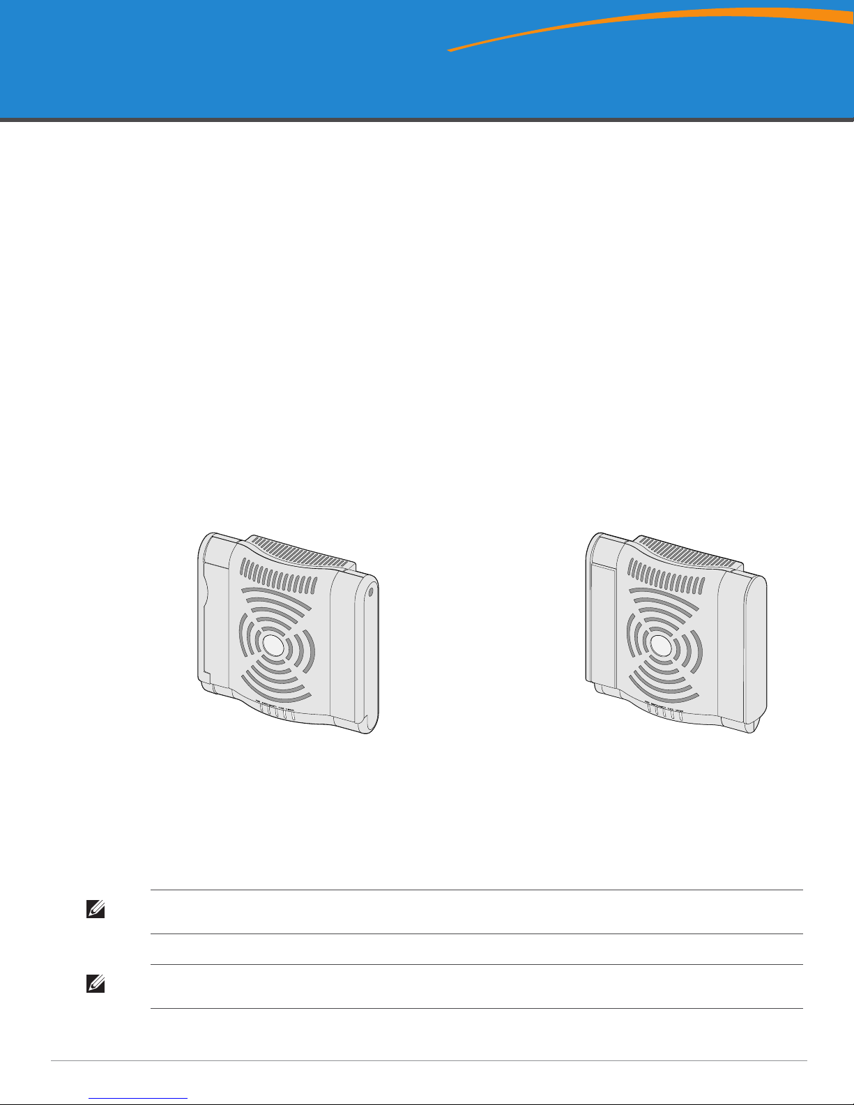
W-AP120/W-AP124
(3 x RP-SMA interfaces for detachable antennas)
W-AP121/W-AP125
(3 x integrated dual-band antennas)
Installation Guide
The Dell W-AP120 series of wireless access points support the imminent IEEE 802.11n (currently draft 2.0)
standard for high-performance WLAN. These access points use MIMO (Multiple-in, Multiple-out) technology
and other high-throughput mode techniques to deliver high-performance, pre-802.11n 2.4 GHz and 5 GHz
functionality while simultaneously supporting existing 802.11a/b/g wireless services. The W-AP120 series access
points are available in versions with single or dual radios and with integrated antennas or RP-SMA interfaces that
support detachable antennas. The W-AP120 series access points work only in conjunction with an Dell controller.
The Dell W-AP120 series access points provide the following capabilities:
z Wireless transceiver
z Protocol-independent networking functionality
z IEEE 802.11a/b/g or 802.11n operation as a wireless access point
z IEEE 802.11a/b/g or 802.11n operation as a wireless air monitor
z Compatibility with IEEE 802.3af PoE as well as high power over Ethernet pre-standards
(PoE + / 802.3at)
z Central management configuration and upgrades through an Dell controller
z Upgrade of W-AP120 series a/b/g models to 802.11n (draft) compliance through a controller license
Figure 1 W-AP120 Series Access Points
Package Contents
z AP-120 series access point
z Installation guide (this document)
Note: Inform your supplier if there are any incorrect, missing, or damaged parts. If possible, retain the carton, including the original
packing materials. Use these materials to repack and return the unit to the supplier if needed.
Note: Additional mounting kits for use with the W-AP120 series access points are sold separately. Contact your Dell sales
representative for details.
0510745-01 | July 2010 1

Before You Begin
WLAN Planning
Determine how many Dell APs are needed for your wireless network deployment and where they will be installed.
You can easily accomplish this planning using Dell’s automated RF Plan site-survey software (available
separately). This process is considered WLAN or RF planning and should have been completed during the master
Dell controller installation and configuration. In typical Dell installations, the controllers are configured and
installed before the APs.
For WLAN planning assistance, refer to the Indoor Access Points: Site Survey and Planning Pre-Deployment Guide
and the RF Plan Installation and User Guide.
Pre-Installation Network Requirements
After WLAN planning is complete and the appropriate products and their placement have been determined, the
Dell controller(s) must be installed and initial setup performed before the Dell Access Points are deployed.
For initial setup of the controller, refer to the ArubaOS Quick Start Guide for the software version installed on
your controller.
Pre-Installation Checklist
Before installing your W-AP120 series access point, be sure that you have the following:
z For the W-AP120/W-AP124: External antennas as specified in the network deployment plan
z CAT5 UTP cable of required length
z One of the following power sources:
IEEE 802.3af-compliant Power over Ethernet (PoE) source
Supports full functionality for W-AP120/W-AP121; supports reduced functionality for W-AP124/W-
AP125
IEEE Power Over Ethernet + (PoE+) source output at 56 Volts @ 350 mA
The POE source can be any power source equipment (PSE) controller or midspan PSE device
Dell AP AC-DC adapter kit (sold separately)
z Dell controller provisioned on the network:
Layer 2/3 network connectivity to your access point
One of the following network services:
z Aruba Discovery Protocol (ADP)
z DNS server with an “A” record
z DHCP Server with vendor-specific options
Summary of the Setup Process
Note: It is important that you verify the items listed under Pre-Installation Checklist before you attempt to set up and install an WAP120 series AP.
Successful setup of an AP-120 series access point consists of five tasks, which must be performed in this order:
1. Verify pre-installation connectivity.
2. Identify the specific installation location for each AP.
3. Install each AP.
4. Verify post-installation connectivity.
2 Dell PowerConnect W-AP120 Series AP | Installation Guide

5. Configure each AP.
Note: Dell, in compliance with governmental requirements, has designed the AP-120 series access points so that only authorized
network administrators can change the settings. For more information about AP configuration, refer to the ArubaOS Quick Start
Guide and ArubaOS User Guide.
Caution: Access points are radio transmission devices and as such are subject to governmental regulation. Network
administrators responsible for the configuration and operation of access points must comply with local broadcast regulations.
Specifically, access points must use channel assignments appropriate to the location in which the access point will be used.
Verifying Pre-Installation Connectivity
Before you install APs in a network environment, make sure that the APs will be able to locate and connect to the
controller when powered on.
Specifically, you must verify the following conditions:
z When connected to the network, each AP is assigned a valid IP address
z APs are able to locate the controller
Refer to the ArubaOS Quick Start Guide for instructions on locating and connecting to the controller.
Unidentified Known RF Absorbers/Reflectors/Interference Sources
Identifying known RF absorbers, reflectors, and interference sources while in the field during the installation
phase is critical. Make sure that these sources are taken into consideration when you attach an AP to its fixed
location.
RF absorbers include:
z Cement/concrete: Old concrete has high levels of water dissipation, which dries out the concrete, allowing for
potential RF propagation. New concrete has high levels of water concentration within the concrete, blocking
RF signals.
z Natural Items: Fish tanks, water fountains, ponds, and trees
z Brick
RF reflectors include:
z Metal Objects: Metal pans between floors, rebar, fire doors, air conditioning/heating ducts, mesh windows,
blinds, chain link fences (depending on aperture size), refrigerators, racks, shelves, and filing cabinets
z Do not place an AP between two air conditioning/heating ducts. Make sure that APs are placed below ducts to
avoid RF disturbances.
RF interference sources include:
z Microwave ovens and other 2.4 or 5 GHz objects (such as cordless phones)
z Lunch rooms and call centers with cordless headsets
Dell PowerConnect W-AP120 Series AP | Installation Guide 3
Installing the AP
Caution: Installation and service of Dell Networks products should be performed by Professional Installers. Additional antenna
and transmit power information for Professional Installers can be found at https://support.dell.com.
Using the Integrated Wall-Mounting Slots
The keyhole-shaped slots on the back of the AP can be used to attach the device upright to an indoor wall or shelf.
When you choose the mounting location, allow additional space at the right of the unit for cables.
Note: For product dimensions, see Product Specifications in this guide. Allow 2 inches (5 cm) of additional space at the right side
of the installed unit for cables, and make sure enough space is available for antenna articulation.
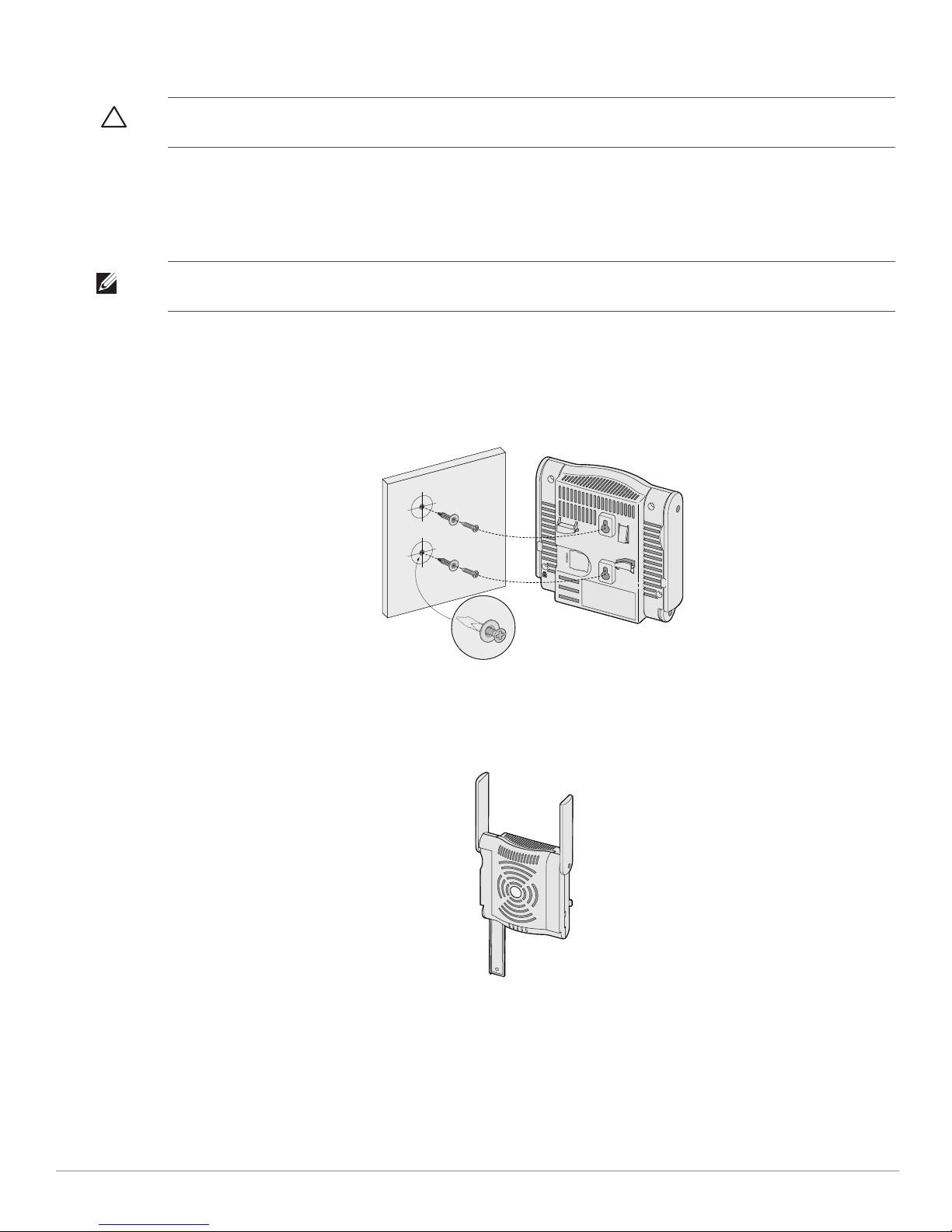
1. At the mounting location, install two screw on the wall or shelf, 1 7/8 inches (4.7 cm) apart. If you are
attaching the device to drywall, Dell recommends using appropriate wall anchors (not included).
2. Align the mounting slots on the rear of the AP over the screws and slide the unit into place (see Figure 2).
Figure 2 Installing the W-AP120 Series Access Point on a Wall
3. On the W-AP121 or W-AP125, orient the antennas. For best performance, swivel the antennas so that they
are oriented vertically, preferably in the same plane, parallel to the wall (see Figure 3).
Figure 3 Antenna Orientation on a Wall-Mounted W-AP121/W-AP125
On the W-AP120 or W-AP124, install the external antennas according to the manufacturer’s instructions,
and connect the antennas to the antenna interfaces on the AP (see Figure 4).
4 Dell PowerConnect W-AP120 Series AP | Installation Guide
 Loading...