

Dell PowerConnect W-6000 Installation Manual

Dell PowerConnect W-6000 Power Supply
Installation Guide
The Dell PowerConnect W-6000 Power Supply adapts electrical power for use with the W-6000. The W-6000
chassis has three slots that can hold individual power supplies to support load sharing and fault tolerance.
This chapter describes the general features and physical characteristics of the power supply and important power
consumption management information. The final sections of the chapter cover the steps required to insert and
remove power supplies.
Features
Rating
The Dell W-6000 Power Supply (HW-PSU-400) is rated at 400 W total output and is auto-ranging to accept 85
to 264 VAC, at 50 to 60 Hz. Up to three 400 W power supplies can be installed in the W-6000.
Load Sharing
Load sharing occurs when more than one power supply of the same rating are installed in the W-6000 and turned
on. Load sharing divides the total power load of the W-6000 among all plugged in power supply modules. Since
the power supplies work together, the effective power capacity of the chassis is increased with each additional
power supply.
Redundancy
When multiple power supplies are installed, if one becomes unavailable (fails, or is turned off or removed) the
remaining power supplies will attempt to provide full power for the W-6000. If the total power load does not
exceed the combined rated output of the remaining, operational power supplies, the W-6000 will continue to
operate. For more information on power supply configurations, “Power Management” on page3.
Hot Swap
Hot swapping should be performed by a trained technician. Hot swapping allows you to replace one failed power
supply while the others provide full power. This makes it unnecessary to shut down the W-6000 during the
replacement procedure.
Hot swapping requires that after the target power supply is removed, the total power load does not exceed the
combined rated output of the remaining power supplies.
0510766-01 | March 2011 1
Physical Description
O.T.P
DC OK
AC OK
176541 2 3
6.5A MAX
1
2
3
4
5
6
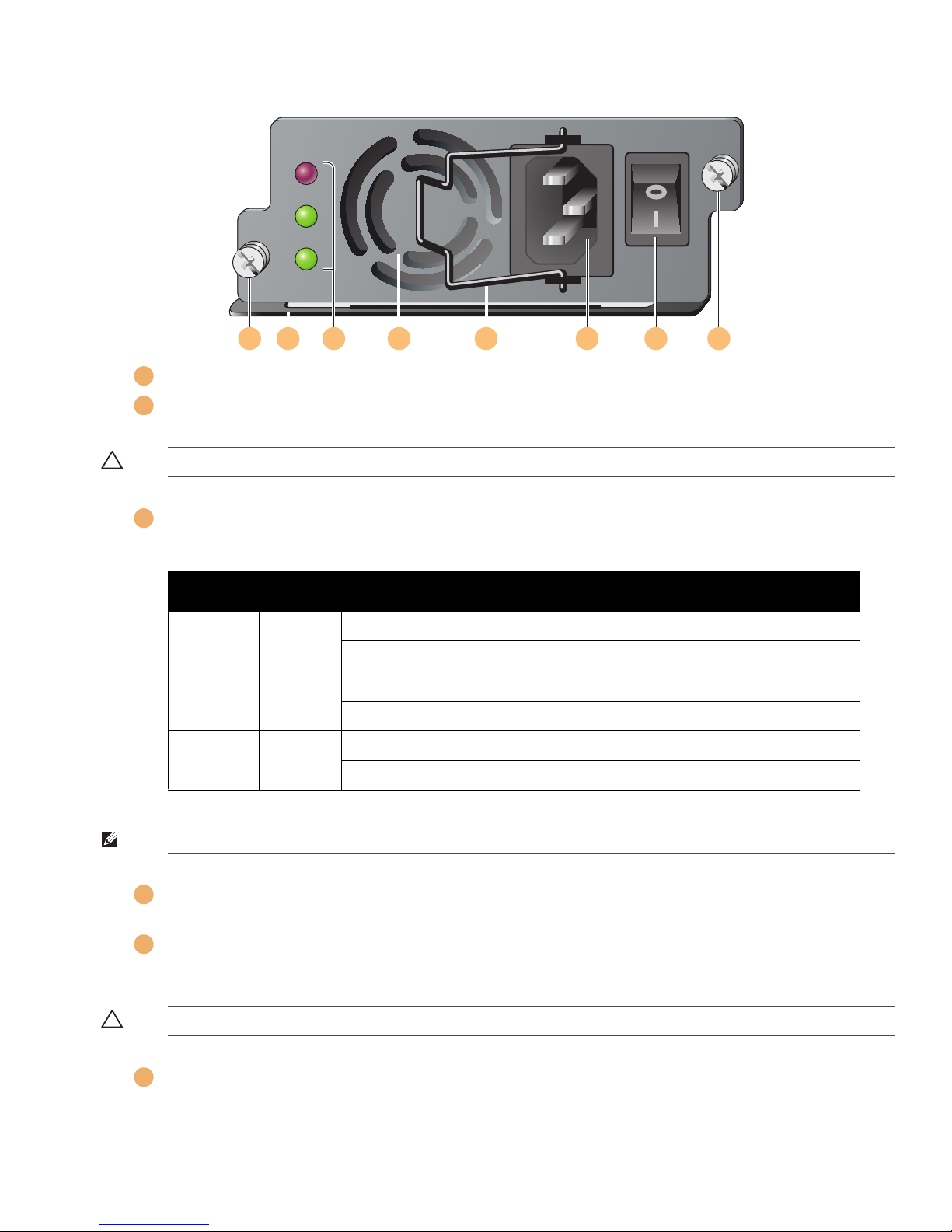
Figure 1 400W Power Supply
Module Fastening Screws: These two captive fastening screws hold the power supply in place in the chassis.
Module Handle: This handle is used for removing or inserting the module into the W-6000 chassis.
CAUTION: Do not use the power supply handle to lift or move the W-6000. Serious damage could result.
Indicator LEDs
Table 1 400W Power Supply LEDs
LED Name Position Status Description
O.T.P.
(Over Temp.
Protection)
DC OK Middle Green DC power output is okay.
AC OK Bottom Green AC power input is okay.
NOTE: In addition to the LEDs, the power supply status can be viewed using the CLI.
Air Intake Vent: This air intake vent helps the internal fan cool the power supply during operation. To prevent
blockage, keep all material at least 10 cm (4 inches) from the vent.
Power Cord Retaining Clip: This clip fits over the power cord once the plug has been inserted into the power
input socket. It helps prevent the power cord from being pulled out accidentally.
Top Off Power supply temperature is okay.
Red Power supply fan has failed or temperature is too high.
Red DC power output is not within tolerance.
Red AC power input is not within tolerance.
CAUTION: Do not use the power cord retaining clip to remove the power supply module, or to lift or move the W-6000.
Power Input Socket: This power socket accepts power cords with standard IEC320 connectors. For proper safety
2 Dell PowerConnect W-6000 Power Supply | Installation Guide
and performance, the cord must be rated to 10 A and conform to grounded electrical standards in the country
where the product is used.
 Loading...