

Page 1

53-1001794-01
January 31, 2010
Power Supply and Filler
Panel
Replacement Procedure
Supporting PowerConnect B-DCX-4S Backbone and PowerConnect B-DCX
Backbone
53-1001794-01
*53-1001794-01*
Page 2

Notes, Cautions, and Warnings
NOTE
CAUTION
CAUTION
DANGER
A NOTE indicates important information that helps you make better use of your computer.
See the safety and regulatory information that shipped with your system. For additional regulatory
information, see the Regulatory Compliance Homepage on www.dell.com at the following location:
www.dell.com/regulatory_compliance.
A CAUTION indicates potential damage to hardware or loss of data if instructions are not followed.
A DANGER indicates a potential for property damage, personal injury, or death.
____________________
Information in this document is subject to change without notice.
© 2009 Dell Inc. All rights reserved.
Reproduction of these materials in any manner whatsoever without the written permission of Dell Inc. is strictly forbidden.
Trademarks used in this text: Dell, the DELL logo, Inspiron, Dell Precision, Dimension, OptiPlex, Latitude, PowerEdge, PowerVault, PowerApp, Dell
OpenManage and the YOURS IS HERE
in the U.S. and other countries; Microsoft, Windows, Windows Server, MS-DOS and Windows Vista are either trademarks or registered trademarks
of Microsoft Corporation in the United States and/or other countries.
Other trademarks and trade names may be used in this document to refer to either the entities claiming the marks and names or their products.
Dell Inc. disclaims any proprietary interest in trademarks and trade names other than its own.
Regulatory Model Codes: Brocade DCX-4S, Brocade DCX
2 Power Supply and Filler Panel Replacement Procedure
logo are trademarks of Dell Inc.; Intel, Pentium, and Celeron are registered trademarks of Intel Corporation
53-1001794-01
Page 3
In this guide
NOTE
•Power supply installation . . . . . . . . . . . . . . . . . . . . . . . . . . . . . . . . . . . . . . . . . 3
•Time and items required . . . . . . . . . . . . . . . . . . . . . . . . . . . . . . . . . . . . . . . . . 3
•Removing a power supply . . . . . . . . . . . . . . . . . . . . . . . . . . . . . . . . . . . . . . . . 4
•Replacing a power supply . . . . . . . . . . . . . . . . . . . . . . . . . . . . . . . . . . . . . . . . 6
Power supply installation
Use this procedure to remove and replace a power supply.
The PowerConnect B-DCX can continue operating during the replacement if:
At least one 220 VAC power supply is operating,
At least two 110 VAC power supplies are working.
The PowerConnect B-DCX-4S can continue operating during the replacement if the second 220 VAC power supply is
operating,
Time and items required
The replacement procedure for each power supply takes less than 5 minutes. A power supply unit or filler panel is
required for the power supply replacement.
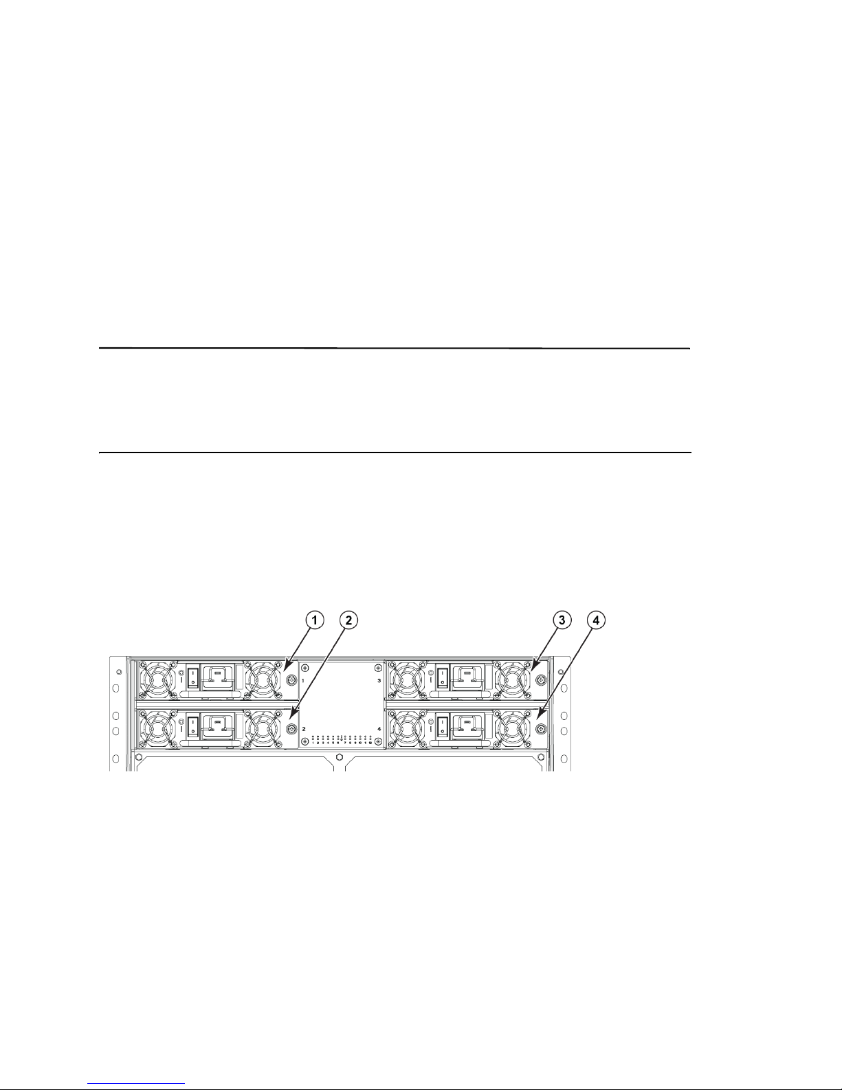
Figure 1 shows the location and identification of the power supplies for the PowerConnect B-DCX.
1 Power supply 1 (PS1) 3 Power supply 3 (PS3)
2 Power supply 2 (PS2) 4 Power supply 4 (PS4)
FIGURE 1 Power supply identification for the PowerConnect B-DCX
Power Supply and Filler Panel Replacement Procedure 3
53-1001794-01
Page 4
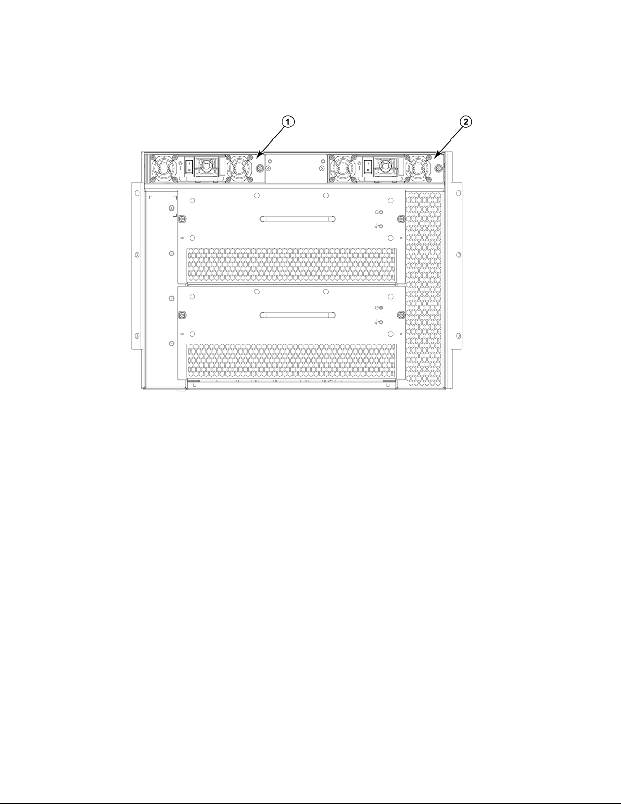
Figure 2 shows the location and identification of the power supplies for the PowerConnect B-DCX-4S.
1 Power supply 1 (PS1) 2 Power supply 2 (PS2))
FIGURE 2 Power supply identification for the PowerConnect B-DCX-4S
Removing a power supply
1. Perform one of the two following tasks:
For the PowerConnect B-DCX:
• If the PowerConnect B-DCX is not operating during the replacement procedure, go to step 2.
• If the PowerConnect B-DCX is operating and will continue to operate during the replacement, check the
power LEDs to verify that the minimum number of power supplies is functioning. A fully populated
PowerConnect B-DCX requires a minimum of one power supply at all times.
For the PowerConnect B-DCX-4S:
• If the PowerConnect B-DCX-4S is not operating during the replacement procedure, go to step 2.
• If the PowerConnect B-DCX-4S is operating and will continue to operate during the replacement, check the
power LEDs to verify that the minimum number of power supplies is functioning. A fully populated
PowerConnect B-DCX-4S requires a minimum of one power supply at all times.
2. Turn off the power switch.
3. Remove the power cord.
4. Loosen the thumb screw on the right side of the power supply.
4 Power Supply and Filler Panel Replacement Procedure
53-1001794-01
Page 5
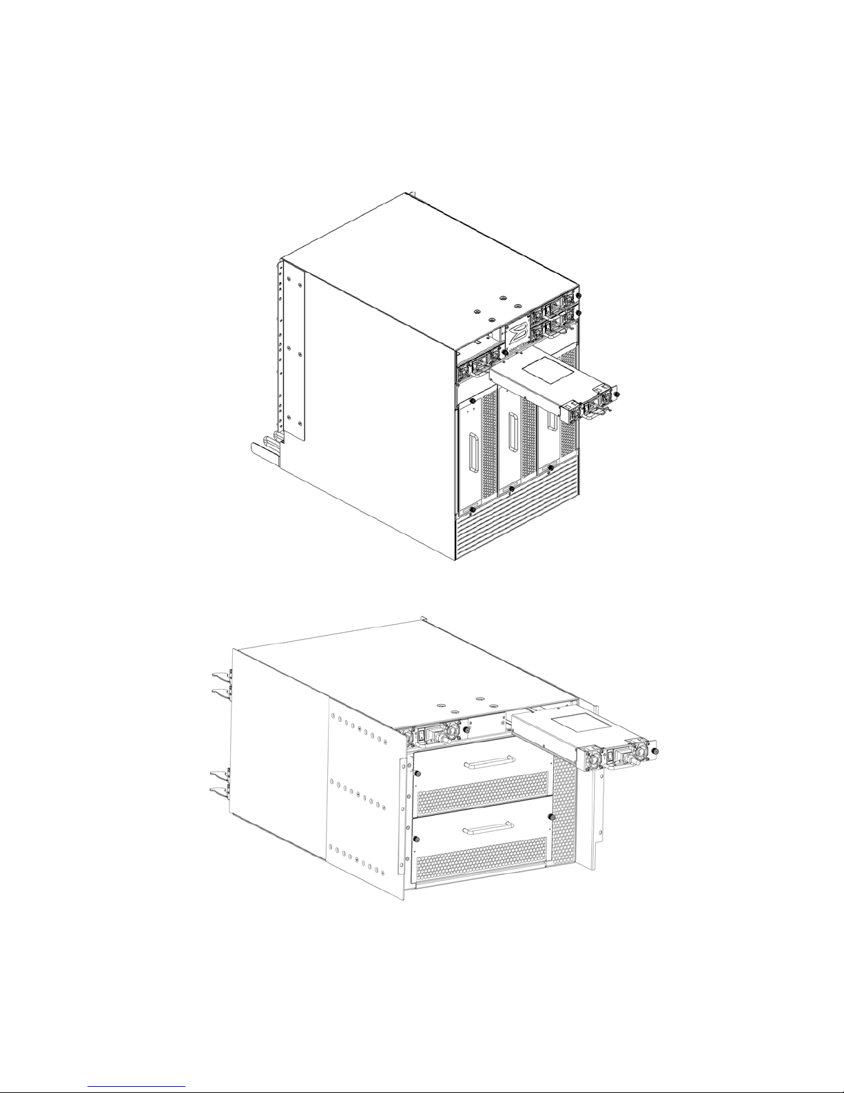
5. Grasp the handle and pull, sliding the power supply from the chassis and supporting the power supply from
beneath as you remove it (Figure 3 or Figure 4).
6. If you are not replacing the power supply, insert a filler panel into the slot.
FIGURE 3 Power supply for the PowerConnect B-DCX
FIGURE 4 Power supply for the PowerConnect B-DCX-4S
Power Supply and Filler Panel Replacement Procedure 5
53-1001794-01
Page 6

Replacing a power supply
1. Remove any filler panel.
2. Insert the power supply into the slot and push the handle up. Verify that the power supply is seated by gently
pulling on the handle.
3. Tighten the thumb screw.
4. Replace the power cord.
5. Turn on the power switch.
6. Verify that the power LED on the power supply displays a steady green light.
6 Power Supply and Filler Panel Replacement Procedure
53-1001794-01
 Loading...