

Page 1
Dell PowerEdge
RAID Controller (PERC) S100,
PERC S300
User’s Guide
Page 2
Notes, Cautions, and Warnings
NOTE:
your computer.
A NOTE indicates important information that helps you make better use of
CAUTION:
A CAUTION indicates potential damage to hardware or loss of data if
instructions are not followed.
WARNING:
A WARNING indicates a potential for property damage, personal
injury, or death.
____________________
Information in this publication is subject to change without notice.
© 2008—2011 Dell Inc. All rights reserved.
Reproduction of these materials in any manner whatsoever without the written permission of Dell Inc.
is strictly forbidden.
Trademarks used in this text: Dell™, the DELL logo, PowerEdge™, and OpenManage™ are
trademarks of Dell Inc. Intel™ is a registered trademark of Intel Corporation in the U.S. and other
countries. AMD
Sempron™ are trademarks of Advanced Micro Devices, Inc. Microsoft
®
Server
and/or other countries.
Other trademarks and trade names may be used in this publication to refer to either the entities claiming
the marks and names or their products. Dell Inc. disclaims any proprietary interest in trademarks and
trade names other than its own.
Models: UCS61, UCS60
February 2011 Rev. A01
are either trademarks or registered trademarks of Microsoft Corporation in the United States
®
is a registered trademark and AMD Opteron™, AMD Phenom™, and AMD
®
, Windows®, and Windows
Page 3

Contents
1 WARNING: Safety Instructions
SAFETY: General
SAFETY: When Working Inside Your System
Protecting Against Electrostatic Discharge
2Overview
Introduction
General Information, Intended Audience, and
Prerequisites for Use
Related Documentation
PERC S100 Adapter or PERC S300 Adapter
Descriptions
. . . . . . . . . . . . . . . . . . . . . . . . .
. . . . . . . . . . . . . . . . . . . . . .
. . . . . . . . . . . . . . . . . . . . . . .
. . . . . . . . . . . . . . . . . .
. . . . . . . . . . . . . . . . .
. . . . . . . . . . . . . . . . . . . . . . .
. . . . . . . . .
. . . . . . .
. . . . . . .
11
7
8
8
9
11
11
12
12
About RAID
RAID Terminology
3 Features
General Features
Specifications
. . . . . . . . . . . . . . . . . . . . . . . .
. . . . . . . . . . . . . . . . . . . .
. . . . . . . . . . . . . . . . . . . . . . . . . .
. . . . . . . . . . . . . . . . . . . . .
. . . . . . . . . . . . . . . . . . . . . .
4 Hardware Installation
Before You Begin
. . . . . . . . . . . . . . . . . . . .
. . . . . . . . . . . . . . .
Contents
17
18
21
21
29
31
31
3
Page 4

General Considerations
. . . . . . . . . . . . . . . . .
31
Installing the PERC S300 Adapter
Connect Physical Disks to the PERC S300 Adapter
Complete the Hardware Installation
5 Installing the Drivers
. . . . . . . . . . . . . . .
Installing the Microsoft Windows Drivers
6 RAID Configuration and
Management
Configuring the Controller: Using the PERC
Virtual Disk Management Utility
7 Troubleshooting
. . . . . . . . . . . . . . . . . . . . . .
. . . . . . . . . . . . . . . . . . .
. . . . . . . . . . . .
. . .
. . . . . . . . . .
. . . . . . .
. . . . . . . . . . . .
32
35
35
37
37
47
47
61
System Startup Problems
Warning Messages: Dell Inc. PERC S100
Adapter or Dell Inc. PERC S300 Adapter
BIOS Screen
Virtual Disk-Related Errors
Physical Disk-Related Errors
8 Appendix A
Controller Specifications
Controller Tasks
Physical Disk Tasks
Virtual Disk Tasks
. . . . . . . . . . . . . . . .
. . . . . . . . . . . . . . . . . . . . . . .
. . . . . . . . . . . . . . .
. . . . . . . . . . . . . .
. . . . . . . . . . . . . . . . . . . . . . .
. . . . . . . . . . . . . . . .
. . . . . . . . . . . . . . . . . . . . .
. . . . . . . . . . . . . . . . . . .
. . . . . . . . . . . . . . . . . . . .
61
64
70
75
77
77
78
78
79
4
Contents
Page 5

Supported RAID Levels
. . . . . . . . . . . . . . . . .
79
Virtual Disk Specifications
9 Appendix B
RAID Technology - Understanding Disk Arrays
and Virtual Disks
10 Appendix C
Regulatory Notices
FCC Notice (U.S. Only)
Industry Canada Notice (Canada Only)
CE Notice (European Union)
CE Mark Notice
. . . . . . . . . . . . . . .
. . . . . . . . . . . . . . . . . . . . . . .
. . . . . . . . . . . . . . . . . . . . .
. . . . . . . . . . . . . . . . . . . . . . .
. . . . . . . . . . . . . . . . . . .
. . . . . . . . . . . . . . . . . .
. . . . . . . . .
. . . . . . . . . . . . . . .
. . . . . . . . . . . . . . . . . . . . .
80
81
81
89
89
90
92
92
94
11 Appendix D
Contacting Dell
Index
Glossary
. . . . . . . . . . . . . . . . . . . . . . . . . . . . . . .
. . . . . . . . . . . . . . . . . . . . . . . . . . . .
. . . . . . . . . . . . . . . . . . . . . . .
. . . . . . . . . . . . . . . . . . . . .
95
95
97
103
Contents
5
Page 6

6
Contents
Page 7
1
WARNING: Safety Instructions
Use the following safety guidelines to help ensure your own personal safety
and to help protect your system and working environment from potential
damage.
WARNING:
(PERC) S300 adapter to liquids. To reduce risk of fire hazard, do not cover or
obstruct the ventilation openings of the system in which it is installed. Do not
install the controller in a zero-clearance compartment. This could result in
overheating.
Do not expose the Dell PowerEdge Expandable RAID Controller
WARNING:
any way.
WARNING:
damaged by static electricity. Be sure that you are properly grounded. It is
recommended that you wear a grounded antistatic strap and that the system is
unplugged before you install the controller.
CAUTION:
PERC S300 adapter. The connectors are keyed to prevent them from being inserted
incorrectly.
CAUTION:
on any pending tasks (such as a rebuild) before it is turned off to conduct a system
upgrade.
CAUTION:
PERC S300 adaper. An update might take up to five minutes per controller.
Do not operate the controller if it has been dropped or damaged in
The controller, like every other electronic part of a system, can be
Cable connectors must be mated carefully with the connectors on the
Ensure that the current RAID controller (if any) is not currently working
During a firmware update, do not reboot the system that contains the
WARNING: Safety Instructions
7
Page 8
SAFETY: General
Observe and follow service markings:
• Do not service any product except as explained in the user documentation.
Opening or removing covers that are marked with a triangular symbol with
a lightning bolt might expose you to electrical shock. Components inside
these compartments must be serviced only by a trained service technician.
• Use the product only with Dell-approved equipment.
• Operate the product only from the type of external power source indicated
on the electrical ratings label. If you are not sure of the type of power
source required, consult your service provider or local power company.
SAFETY: When Working Inside Your System
Before you remove the system covers, perform the following steps in the
sequence indicated.
WARNING:
covers from the system, and access any of the internal components, unless the
Dell documentation expressly states otherwise.
Only trained service technicians are authorized by Dell to remove
CAUTION:
after turning off the system before disconnecting the controller.
1
Turn off the system and any devices.
2
Wear grounding straps that are properly grounded before touching
anything inside the system.
3
While you work, periodically touch an unpainted metal surface on the
chassis to dissipate any static electricity that might harm internal
components.
4
Disconnect your system and devices from their power sources. To reduce
the potential of personal injury or shock, disconnect any
telecommunication lines from the system.
To help avoid possible damage to the system board, wait five seconds
8
WARNING: Safety Instructions
Page 9

In addition, take note of these safety guidelines when appropriate:
• When you disconnect any cable, pull on its connector or on its strain-relief
loop, not on the cable itself. Some cables have a connector with locking
tabs. If you are disconnecting this type of cable, press in on the locking
tabs before disconnecting the cable. As you pull connectors apart, keep
them evenly aligned to avoid bending any connector pins. Also, before you
connect a cable, make sure that both connectors are correctly oriented and
aligned.
• Handle the controller with care. Do not touch the components or contacts
on the controller.
Protecting Against Electrostatic Discharge
Electrostatic discharge (ESD) events can harm electronic components inside
your system. ESD, or electrostatic discharge, is the process by which static
electricity can build up within a person or an object, and then discharge into
another object. ESD events can harm your PERC S300 adaper, your system,
and other electrical components. To prevent ESD damage, you must
discharge static electricity from your body before you interact with any of the
system’s internal electronic components. You can protect against ESD by
touching a metal grounded object (such as an unpainted metal surface on
your system’s I/O panel) before you interact with anything electronic. In
addition, as you work inside the system, periodically touch an I/O connector
to remove any static charge your body might have accumulated.
You can also take the following steps to prevent damage from electrostatic
discharge:
• When unpacking the controller from its shipping carton, do not remove
the controller from the antistatic packing material until you are ready to
install it. Just before unwrapping the antistatic package, be sure to
discharge static electricity from your body.
• Handle all electrostatic sensitive components in a static-safe area. If
possible, use anti-static floor pads and work bench pads.
WARNING: Safety Instructions
9
Page 10

10
WARNING: Safety Instructions
Page 11

2
Overview
Introduction
The Dell PowerEdge RAID Controller (PERC) S300 provides an integrated
software RAID solution for Dell PowerEdge Value Servers. The PERC S300
controllers support SAS and SATA interfaces. Containing two internal
connectors with four ports each, the PERC S300 adapter features
eight ports for connecting drives with a maximum burst speed of up to
3 Gbps per port.
The PERC S100 adaper is targeted as a low-cost RAID solution for Dell
PowerEdge Value Servers. The PERC S100 adapter solution supports SATA
Hard Disk Drives (HDD) and Solid State Disk (SSD) drives. The PERC S100
adapter requires no additional hardware; it runs from the I/O Controller HUB
(ICH) or Platform Controller Hub (PCH) chipset on the platform
motherboard.
The PERC S100 adapter and PERC S300 adapter offer the same RAID level
support and functionality, including the support of up to eight physical
drives.
General Information, Intended Audience, and
Prerequisites for Use
This document provides information about:
•The
• Controller configuration and startup procedures
• Controller operating modes
PERC S100 adapter
operating system, and software support
and PERC S300 adapter, including server,
Overview
11
Page 12

This document is intended for use by system administrators and technicians
who are familiar with the storage system installation and configuration.
Prerequisites for configuring and using the controller include familiarity with:
• Servers and computer networks
• RAID technology
• Storage-interface technology, such as SAS and SATA
Related Documentation
For more information about the PERC S100 adapter or PERC S300 adapter
and its relationship to the Dell OpenManage Server Administrator Storage
Management documentation, see the Storage Management documentation
available on the Dell Support website at support.dell.com/manuals.
PERC S100 Adapter or PERC S300 Adapter
Descriptions
The following list describes each type of controller:
• The PERC S300 Adapter has two internal connectors with x4 SAS ports.
• The PERC S300 Modular has two internal connectors with x4 SAS ports.
• The PERC S100 adapter runs on the ICH or PCH chipset on the platform
motherboard.
12
Overview
Page 13

Supported Platforms
Table 2-1. Dell Systems and Support Matrix for the PERC S100 Adapter and
PERC S300 Adapter
PowerEdge Server PERC Controller, with Chipset and Adapter Support per Platform
PowerEdge R210 PERC S100 adapter – Intel Ibex Peak chipsets
PERC S300 adapter – Dell 3Gb/s SAS Adapter
PowerEdge R210 II PERC S100 adapter – Intel Cougar Point chipsets
PERC S300 adapter – Dell 3Gb/s SAS Adapter
PowerEdge R310 PERC S100 adapter – Intel Ibex Peak chipsets
PERC S300 adapter – Dell 3Gb/s SAS Modular
PowerEdge R410 PERC S100 adapter – Intel ICH10R chipsets
PERC S300 adapter – Dell 3Gb/s SAS Modular
PowerEdge R415 PERC S300 adapter – Dell 3Gb/s SAS Modular,
AMD SP5100 South Bridge chipsets
PowerEdge R510 PERC S100 adapter – Intel ICH10R chipsets,
PERC S300 adapter – Dell 3Gb/s SAS Adapter
PowerEdge R515 PERC S300 adapter – Dell 3Gb/s SAS Adapter,
AMD SP5100 South Bridge chipsets
PowerEdge T110 PERC S100 adapter – Intel Ibex Peak chipsets
PERC S300 adapter – Dell 3Gb/s SAS Adapter
PowerEdge T110 II PERC S100 adapter – Intel Cougar Point chipsets
PERC S300 adapter – Dell 3Gb/s SAS Adapter
PowerEdge T310 PERC S100 adapter – Intel Ibex Peak chipsets
PERC S300 adapter – Dell 3Gb/s SAS Adapter
PowerEdge T410 PERC S100 adapter – Intel ICH10R chipsets
PERC S300 adapter – Dell 3Gb/s SAS Adapter
Overview
13
Page 14

Platform Requirements for the PERC S100 Controller and PERC S300
Controller
Table 2-2. Platform Requirements — PERC S100 Controller or PERC S300 Controller
Component Requirements
Processor x86, 32-bit compatible processor greater than 500 MHz.
Memory 512 MB or greater.
Physical
disk
Ports
Available
slots
At least one Hard Disk Drives (HDD) or Solid State Disk (SSD) Drives.
NOTE:
4 SATA HDD or 4 SATA SSD physical disks. The PERC S300 controller
supports cabled or hot-swap configurations of up to 8 SATA or SAS HDD
physical disks.
• SATA-II HDD physical disks can be used with a PERC S100 adapter or
• SATA-II SSD physical disks can be used only with a PERC S100
• SAS HDD physical disks can be used only with a PERC S300 adapter.
• The S300 Adapter has two 8470-type internal SAS connectors on the
• The S300 Modular typically plugs into a backplane that has a single
The PERC S300 Adapter and PERC S300 Modular cards plug into
8-lane Peripheral Component Interconnect Express (PCI-E) slots.
The PERC S100 controller supports cabled configurations of up to
a PERC S300 adapter.
adapter.
adapter card. Each mini-SAS connector supports 4 SAS/SATA ports.
8470-type SAS connector (except for PERC S300 adapters on an R210
or T110, whose cables plug directly into the physical disks).
14
Overview
Page 15

Table 2-2. Platform Requirements — PERC S100 Controller or PERC S300 Controller
Component Requirements
Operating
systems
• Microsoft Windows Essential Business Server (x64)
• Microsoft Windows Server 2008 Datacenter Edition (x64)
• Microsoft Windows Server 2008 Enterprise Edition (x64)
• Microsoft Windows Server 2008 Enterprise Edition (x86)
• Microsoft Windows Server 2008 Foundation
• Microsoft Windows Server 2008 HPC Edition
• Microsoft Windows Server 2008 R2 Datacenter
• Microsoft Windows Server 2008 R2 Datacenter SP1
• Microsoft Windows Server 2008 R2 Enterprise
• Microsoft Windows Server 2008 R2 Enterprise SP1
• Microsoft Windows Server 2008 R2 Foundation
• Microsoft Windows Server 2008 R2 Foundation SP1
• Microsoft Windows Server 2008 R2 HPC Edition
• Microsoft Windows Server 2008 R2 Standard
• Microsoft Windows Server 2008 R2 Standard SP1
• Microsoft Windows Server 2008 SP2 Datacenter Edition (x64)
• Microsoft Windows Server 2008 SP2 Enterprise Edition (x64)
• Microsoft Windows Server 2008 SP2 Enterprise Edition (x86)
• Microsoft Windows Server 2008 SP2 Standard Edition (x64)
• Microsoft Windows Server 2008 SP2 Standard Edition (x86)
• Microsoft Windows Server 2008 SP2 Web Edition (x64)
• Microsoft Windows Server 2008 SP2 Web Edition (x86)
• Microsoft Windows Server 2008 Standard Edition (x64)
• Microsoft Windows Server 2008 Standard Edition (x86)
• Microsoft Windows Server 2008 R2, 64-bit, Standard and Enterprise
Edition
• Microsoft Windows Server 2008 64-bit Web Edition
Overview
15
Page 16

Table 2-2. Platform Requirements — PERC S100 Controller or PERC S300 Controller
Component Requirements
• Microsoft Windows Server 2008 Web Edition (x64)
• Microsoft Windows Server 2008 Web Edition (x86)
• Microsoft Windows Small Business Server 2008
• Microsoft Windows Small Business Server 2008 SP2
• Microsoft Windows Small Business Server 2003 R2 SP2 (x86 or x64)
• Microsoft Windows Small Business Server 2011
• Microsoft Windows Web Server 2008 R2
• Microsoft Windows Web Server 2008 R2 SP1
• Microsoft Windows Server 2003 SP2 (x86 or x64)
•Microsoft Windows
Enterprise Edition
• Microsoft Windows Server 2003 R2 SP2 32-bit Web Edition
• Microsoft Windows Server 2008 SP2, 32-bit or 64-bit, Standard and
Enterprise Edition
Server 2003 R2 SP2, 32-bit or 64-bit, Standard and
Supported
devices
NOTE:
NOTE:
NOTE:
with Windows Hyper-V.
• PERC S100 adapter: supports Dell-supported SATA-based tape devices
NOTE:
Dell RD1000 tape device. Select Continue while in CTRL-R for RD1000 to
remain first in the boot order. The RD1000 option goes to end of the boot
order listing if <Ctrl><Alt><Del> is selected and you would not be able to
boot to it.
• PERC S300 adapter: does not support tape devices or SATA optical disk
Microsoft Windows Server 2003 SP1 is not supported.
Microsoft Windows Server 2003 R2 is not supported.
PERC S100 controllers and PERC S300 controller are not supported
and SATA optical disk devices.
The PERC S100 controller supports system boot to a tape using a
devices.
16
Overview
Page 17
About RAID
A RAID disk array is a group of independent physical disks that provides high
performance by increasing the number of drives used for saving and accessing
data. A RAID disk subsystem improves I/O performance and data availability.
The physical disks appear to the host system either as a single storage unit or
multiple logical units. Data throughput improves because several disks are
accessed simultaneously. RAID systems also improve data storage availability
and fault tolerance. Data loss caused by a physical disk failure can be
recovered by rebuilding missing data from the remaining physical disks
containing data or parity.
NOTE:
is no redundancy for this RAID level. However, when a physical disk in a
RAID 1, RAID 5, or RAID 10 fails, data is preserved because there is redundancy
with these RAID levels.
Summary of RAID Levels
When a physical disk in a RAID 0 virtual disk fails, data is lost because there
•Volume
logical volume on which data is stored.
• RAID 0 uses disk striping to provide high data throughput, especially for
large files in an environment that requires no data redundancy.
• RAID 1 uses disk mirroring so that data written to one physical disk is
simultaneously written to another physical disk. RAID 1 is good for small
databases or other applications that require small capacity but also
complete data redundancy.
• RAID 5 uses disk striping and parity data across all physical disks
(distributed parity) to provide high data throughput and data redundancy.
• RAID 10 uses disk striping across two mirrored sets. It provides high data
throughput and complete data redundancy.
uses available space on a single physical disk and forms a single
Overview
17
Page 18
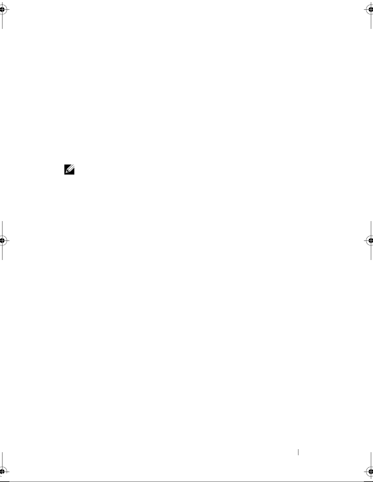
RAID Terminology
Stripe element 1
Stripe element 5
Stripe element 9
Stripe element 2
Stripe element 6
Stripe element 10
Stripe element 3
Stripe element 7
Stripe element 11
Stripe element 4
Stripe element 8
Stripe element 12
Disk Striping
Disk striping allows you to write data across multiple physical disks instead of
just one physical disk. Disk striping involves partitioning each physical disk
storage space into stripes of the various sizes. These stripes are interleaved in
a repeated sequential manner. The part of the stripe on a single physical disk
is called a stripe element.
For example, in a four-disk system using only disk striping (used in RAID
level 0), segment 1 is written to disk 1, segment 2 is written to disk 2, and so
on. Disk striping enhances performance because multiple physical disks are
accessed simultaneously, but disk striping does not provide data redundancy.
Figure 2-1 shows an example of disk striping.
Figure 2-1. Example of Disk Striping (RAID 0)
18
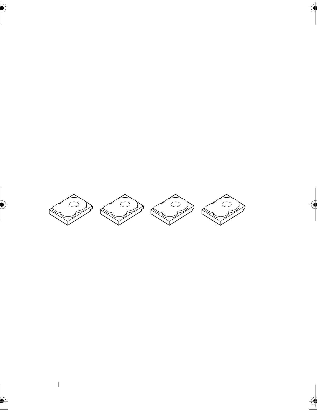
Disk Mirroring
With mirroring (used in RAID 1), data written to one disk is simultaneously
written to another disk. If one disk fails, the contents of the other disk can be
used to run the system and rebuild the failed physical disk. The primary
advantage of disk mirroring is that it provides 100 percent data redundancy.
Because the contents of the disk are completely written to a second disk, it
does not matter if one of the disks fails. Both disks contain a copy of the same
data at all times. Either of the physical disks can act as the operational
physical disk. Disk mirroring provides 100 percent redundancy, but is
expensive because each physical disk in the system must be duplicated.
Figure 2-2 shows an example of disk mirroring.
Overview
Page 19
Stripe element 1
Stripe element 2
Stripe element 3
Stripe element 1 Duplicated
Stripe element 2 Duplicated
Stripe element 3 Duplicated
Stripe element 4 Stripe element 4 Duplicated
NOTE:
NOTE:
devices cannot be migrated to a PERC S300 controller.
Figure 2-2. Example of Disk Mirroring (RAID 1)
Mirrored physical disks improve read performance by read load balancing.
The PERC S300 controller only supports physical disks (SAS and SATA). SSD
Spanned RAID Levels
Spanning is a term used to describe the way in which RAID level 10 is
constructed from multiple sets of simpler RAID levels. For example, a RAID
10 has multiple sets of RAID 1 disk arrays in which each RAID 1 set is
considered a span. Data is then striped (as it is in RAID 0) across the RAID 1
spans to create a RAID 10 virtual disk.
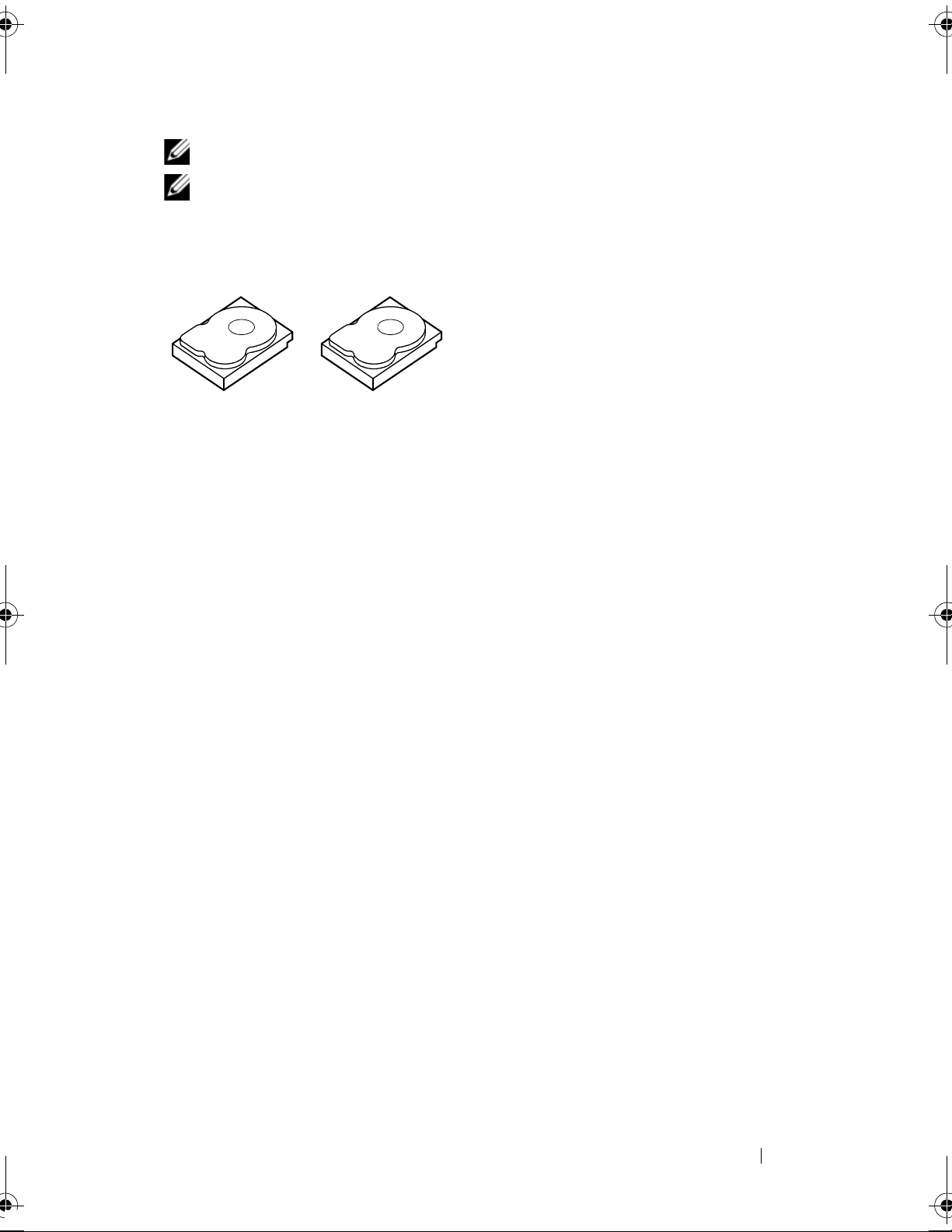
Parity Data
Parity data is redundant data that has been generated to provide fault
tolerance within certain RAID levels. In the event of a drive failure, the parity
data can be used by the controller to regenerate user data. Parity data is
present only for RAID 5 disk arrays.
The parity data is distributed across all the physical disks in the system. If a
single physical disk fails, it can be rebuilt from the parity and the data on the
remaining physical disks. RAID 5 combines distributed parity with disk
striping, as shown in Figure 2-3. Parity provides redundancy for one physical
disk failure without duplicating the contents of entire physical disks.
Overview
19
Page 20
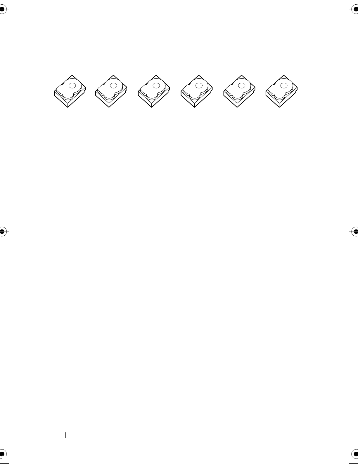
Figure 2-3. Example of Distributed Parity (RAID 5)
stripe element1 stripe element2 stripe element3 stripe element4 stripe element5 parity (1-5)
stripe element7 stripe element8 stripe element9 stripe element10 parity (6-10) stripe element6
stripe element13 stripe element14 stripe element15 parity (11-15) stripe element11 stripe element12
stripe element19 stripe element20 parity (16-20) stripe element16 stripe element17 stripe element18
stripe element25 parity (21-25) stripe element21 stripe element22 stripe element23 stripe element24
parity (26-30) stripe element26 stripe element27 stripe element28 stripe element29 stripe element30
20
Overview
Page 21
3
Features
General Features
The features of the Dell PowerEdge RAID Controller (PERC) S100 and
PERC S300 adapter are described in Table 3-1.
NOTE:
Table 3-1. Features of the PERC S100 controller and PERC S300 controller
RAID Controller Feature Description
BAS, BGI, CC and OCE run only on the operating system.
Automatic virtual disk
rebuild
Background Array
Scan (BAS)
Background virtual
disk initialization
(BGI)
Rebuilds a redundant virtual disk automatically when a
failure is detected, if a hot spare is assigned for this capability.
Verifies and corrects correctable media errors on mirror,
volume, or parity data for virtual disks. BAS starts
automatically after a Virtual Disk is created while in the OS.
The background initialization of a redundant virtual disk
creates the parity data that allows the virtual disk to maintain
its redundant data and survive a physical disk failure.
Because background initialization helps the controller to
identify and correct problems that might occur with the
redundant data at a later time, background initialization is
similar to a consistency check.
Background initialization allows a redundant virtual disk to
be used immediately. Data is lost if a physical disk fails before
the completion of a BGI.
NOTE:
Disk Management utility, the PERC S100 adapter/PERC S300
adapter drivers must be loaded before the BGI runs.
Although a BGI is software-initiated at the PERC Virtual
NOTE:
Management utility refers to both the PERC S100 Virtual Disk
Management utility and the PERC S300 Virtual Disk
Management utility.
Unless mentioned otherwise, the term PERC Virtual Disk
Features
21
Page 22
Table 3-1. Features of the PERC S100 controller and PERC S300 controller
RAID Controller Feature Description
(continued)
Boot support for RAID
levels
Boot support for
degraded virtual disks
Cache support for
virtual disks
Checkpointing Allows different types of checkpointing (background
Command queuing Command queuing is a command protocol used by SATA
Allows boot support for Volume, RAID 0, RAID 1, RAID 5,
and RAID 10.
Enables the system to boot from degraded redundant virtual
disks (RAID 1, RAID 5, or RAID 10).
Supports these cache options: None, Read Only, Read/Write.
The PERC S100 adapter or PERC S300 adapter uses part of
system memory for cache.
initialization, consistency check, and rebuild) to resume at
the last point following a restart.
After the system restarts, background checkpointing resumes
at its most-recent checkpoint.
and SAS physical disks that is supported by the PERC S100
adapter and PERC S300 adapter.
Command queuing allows the host to issue multiple
input/output requests to a disk simultaneously. The disk can
then decide in which order to process the commands to
achieve maximum performance.
22
The SATA and SAS versions of command queuing have
slightly different protocols and means of handling multiple
traffic requests at the same time, but the end-purposes are
comparable.
Features
Page 23

Table 3-1. Features of the PERC S100 controller and PERC S300 controller
RAID Controller Feature Description
(continued)
Consistency check
(CC)
Disk initialization For physical disks, initialization writes metadata to the
Fault tolerance The following fault tolerance features are available with the
A consistency check is a background operation that verifies
and corrects the mirror or parity data for fault-tolerant
physical disks. It is recommended that you periodically run a
consistency check on the physical disks.
By default, a consistency check corrects mirror or parity
inconsistencies. After the data is corrected, the data on the
primary physical disk in a mirror set is assumed to be the
correct data and is written to the secondary physical disk in
the mirror set.
A consistency check cannot be user-initiated in the PERC
Virtual Disk Management utility. However, a consistency
check can user-initiated when using Dell OpenManage Server
Administrator Storage Management.
physical disk, so that the controller can use the physical disk.
PERC S100 adapter and PERC S300 adapter, in order to
prevent data loss in case of a failed physical disk:
• Physical disk failure detection (automatic).
• Virtual disk rebuild using hot spares (automatic, if the hot
spare is configured for this functionality).
• Parity generation and checking (RAID 5 only).
• Hot-swap manual replacement of a physical disk without
rebooting the system (only for systems with a backplane that
allows hot-swapping).
If one side of a RAID 1 (mirror) fails, data can be rebuilt by
using the physical disk on the other side of the mirror.
If a physical disk in RAID 5 fails, parity data exists on the
remaining physical disks, which can be used to restore the
data to a new, replacement physical disk configured as a hot
spare.
If a physical disk fails in RAID 10, the virtual disk remains
functional and data is read from the surviving mirrored
physical disk(s). A single disk failure in each mirrored set can
be sustained, depending on how the mirrored set fails.
Features
23
Page 24

Table 3-1. Features of the PERC S100 controller and PERC S300 controller
RAID Controller Feature Description
Mirror rebuilding A broken mirror can be rebuilt after a new physical disk is
inserted and the physical disk is designated as a hot spare.
The system does not have to be rebooted.
(continued)
Online Capacity
Expansion (OCE)
Physical disks
(general)
OCE is a process that allows you to add storage capacity to an
existing virtual disk. In most cases additional storage capacity
can be added without taking the system offline. However, if
an additional physical disk needs to be added and the system
does not support hot-swapping, the system must be turned
off.
OCE enables you to increase the total storage capacity of a
virtual disk by integrating unused storage with the virtual
disk.
Data can be accessed while the physical disks are added (if a
system has hot-swap capability) and while data on the virtual
disk is being redistributed.
For Volume and RAID 1, OCE expands the virtual disk by
using the available space of the physical disks that are already
members of the virtual disk. For RAID 0, RAID 5 and RAID
10, additional capacity can be attained by adding physical
disks to the virtual disk.
The PERC S100 adapter supports up to four SATA HDD or
SSD physical disks. The PERC S300 adapter supports up to
eight SAS or SATA HDD physical disks.
24
Features
NOTE:
interface and drive type (HDD or SSD). For example, you cannot
mix a SATA and SAS interface (HDD or SSD), or HDD and SSD
physical disks, in the same virtual disk.
A maximum of eight physical disks can be used for RAID 0
and RAID 5. A maximum of two physical disks can be used
for RAID 1. A maximum of four physical disks can be used for
RAID 10.
If a physical disk fails during system startup, the controller
identifies the failed physical disk as follows:
• At the PERC Virtual Disk Management utility by
The physical disks in a virtual disk must be the same
highlighting the failed physical disk in a virtual disk in red.
Page 25

Table 3-1. Features of the PERC S100 controller and PERC S300 controller
RAID Controller Feature Description
(continued)
Physical disk
hot-swapping
(hot-swap capability)
• In a brief warning at the
or
BIOS
that a virtual disk(s) were found that are
Failed
• At Dell OpenManage Server Administrator Storage
Management.
• With a bi-color Status LED on each physical disk. The green
element of the Status LED is off, while the amber element
flashes on and off.
NOTE:
adapter and a backplane that has removable physical disks.
NOTE:
capacity 2 TB and greater. Current and upcoming releases of
PERC S300 adapters will only support upto 2 TB HDD physical
disks .
Hot-swap (hot-plug) capability is the manual substitution of
a physical disk for another one while the host system is
powered on.
If a system supports hot-swapping, physical disks can be
plugged into a system’s backplane while the controller is
operating, without causing the controller to reset.
Dell Inc. PERC S300 Controller BIOS
. This alerts the user to the failed physical disk(s).
The Status LED applies only to systems with a PERC S300
PERC S100 adapters support HDD physical disks of
Dell Inc. PERC S100 Controller
screen,
Degraded
and/or
CAUTION:
only if the system has a PERC S300 adapter and a backplane
that supports hot-swapping.
NOTE:
system’s cover is removed, the physical disks cannot be hotswapped. The physical disks must be located on the backplane
(behind the removable front panel) and accessible externally.
NOTE:
already been created, make sure that SAS HDD physical disks
are replaced with SAS HDD physical disks, that SATA HDD
physical disks are replaced with SATA HDD physical disks, and
that SATA SSD physical disks are replaced with SATA SSD
physical disks.
NOTE:
new disk is of equal or greater capacity to the physical disk that
is being replaced.
A physical disk can be hot-swapped from a system
If a system’s physical disks are accessible only when the
When replacing physical disks in a virtual disk that has
When hot-swapping a physical disk, make sure that the
Features
25
Page 26

Table 3-1. Features of the PERC S100 controller and PERC S300 controller
RAID Controller Feature Description
Physical disk roaming The controller supports moving a physical disk from one
backplane slot or cable connection to another (on the same
controller). The controller automatically recognizes the
repositioned physical disk and logically places it in the proper
order.
(continued)
WARNING:
roaming while an OCE is running at Storage Management.
NOTE:
add parts, see the Hardware Owner’s Manual, available on the
Dell Support website at support.dell.com/manuals.
Perform the following steps for physical disk roaming:
NOTE:
backplane with hot-swap capability.
NOTE:
configuration data on the physical disks.
For more information on how to open the system and
These steps do not apply to systems that have a
1
Turn off the power to the system, physical disks, and system
components.
2
Disconnect the power cables from the system.
3
Move the physical disks to different slots on the backplane
or to different cable connections.
4
Perform a safety check. Make sure the physical disks are
inserted properly.
5
Connect the power cables and power up the system.
The controller detects the RAID configuration from the
A virtual disk is lost if you perform disk
Storage port (Storport)
driver support
Stripe size Stripe size is determined by a PERC S100 adapter/PERC
26
Features
For use with
Storport driver improves throughput and miniport driver
interfaces.
S300 adapter algorithm. Stripe size cannot be configured by
the user.
Microsoft Windows Server
2003 and later, the
Page 27

Table 3-1. Features of the PERC S100 controller and PERC S300 controller
RAID Controller Feature Description
Virtual disks (general) Up to eight virtual disks are supported.
The PERC S100 adapter and PERC S300 adapter allows:
• Creating virtual disks of different RAID levels on a single
controller.
• Creating different RAID level virtual disks on the same
physical disk, to adapt each virtual disk to the I/O that it
processes.
• Building different virtual disks with different characteristics
for different applications.
The PERC S100 adapter and PERC S300 adapter does not
allow:
• Creating a virtual disk from a mix of different type physical
disks. For example, a RAID 10 virtual disk cannot be created
from two SATA-II HDD physical disks, a SAS HDD physical
disk, and a SSD physical disk. All of the physical disks must
be the same interface (SAS or SATA) and drive type (HDD
or SSD).
(continued)
• Selecting a physical disk as a dedicated hot spare if the
physical disk is a different type from the physical disk or
disks.
A virtual disk refers to data storage created by the controller
from one or more physical disks. Although a virtual disk can
be created from several physical disks, it is seen by the
operating system as a single disk.
The capacity of a virtual disk can be expanded online for any
RAID level, without the operating system being rebooted.
Features
27
Page 28

Table 3-1. Features of the PERC S100 controller and PERC S300 controller
RAID Controller Feature Description
Virtual disk migration The controller supports automatic virtual disk migration
from a PERC S100 adapter to a PERC S300 adapter (or vice
versa). Manual intervention for migration is not required or
used by the PERC S100 adapter or
PERC S300 adapter.
(continued)
Virtual disk RAID
levels
Virtual disk
transformation
CAUTION:
down both systems before removing or inserting the physical
disks. After the migration occurs, make sure that all of the
physical disks have been migrated and are present in the
virtual disk.
CAUTION:
migration during an OCE.
NOTE:
SATA SSD disks. SAS disks cannot be migrated with a
PERC S100 adapter.
NOTE:
dissimilar controllers or dissimilar system models when the
system uses Microsoft Windows Server 2003 as its operating
system.
Virtual disks at different RAID levels can be created.
Virtual disk transformation can consist of:
• Capacity expansion, using OCE (to allocate additional
virtual disk space on the original physical disks or after
additional physical disks are added).
Before starting a virtual disk migration, power-
The virtual disk is lost if you perform a virtual disk
The PERC S100 adapter only supports SATA HDD and
A bootable virtual disk cannot be migrated between
28
• Rebuilding (rebuilding data on a virtual disk consists of
using an available hot spare or backup physical disk).
Features
Page 29

Specifications
Table 3-2 compares the specifications of the PERC S100 adapter and PERC
S300 adapter.
Table 3-2. Specifications for the PERC S100 adapter and PERC S300 adapter
Specification PERC S100 adapter PERC S300 adapter
SAS technology No Yes
SATA technology Yes Yes
eSATA technology Yes No
SSD technology Yes No
Support for x8 PCI-E Host Interface No Yes
I/O Controller Intel ICH10R or
Intel Ibex Peak chipsets
or Intel Cougar Point
chipsets
Communication to the system Integrated PCI-E lanes
Communication to end devices SATA links SAS/SATA links
SAS connectors No Two 4-port connectors
SATA connectors Discrete on the
motherboard
Lead-free Yes Yes
Supported operating systems Microsoft Windows Server 2003 Family,
Microsoft Windows Server 2008 Family,
Microsoft Windows Server 2008 R2
Dell-compliant SATA compatibility Yes Yes
Dell-compliant SAS compatibility No Yes
Dell 3Gb/s SAS
Adapter
on all systems
Two 4 -po rt c onn ect ors
on all systems
Dell-supported direct-connected
end devices
*SMART error support through
management applications
Backplane supported systems No Yes
Dell-compliant
physical disks
Yes Ye s
Dell-compliant
physical disks
Features
29
Page 30
Table 3-2. Specifications for the PERC S100 adapter and PERC S300 adapter
Specification PERC S100 adapter PERC S300 adapter
Software-based RAID Volume, RAID 1,
RAID 0, RAID 5,
RAID 10
Maximum number of virtual disks 8 8
Support for internal tape drive Yes No
Support for global hot spare Yes Yes
Maximum number of hot spares Varies (by the number
of free disks in the
system)
Volume, RAID 1,
RAID 0, RAID 5,
RAID 10
Varies (by the number
of free disks in the
system)
*SMART is supported under the Windows Driver but is not supported with
Unified Extensible Firmware Interface (UEFI) and CTRL-R. The SWRAID
SMART drive status shows as "Degraded" in OpenManage Storage Services
(OMSS).
30
Features
Page 31

4
Hardware Installation
Before You Begin
This chapter describes how to install the Dell PowerEdge RAID Controller
(PERC) S300 adapter.
NOTE:
Hardware installation instructions are not required for a system with a PERC S100
controller.
General Considerations
WARNING:
safety instructions that were shipped with your system. For additional safety
information, see the Regulatory Compliance Homepage on dell.com at the
following location: dell.com/regulatory_compliance.
The PERC S100 controller is an integral component of the motherboard.
Before you begin any of the procedures in this chapter, follow the
WARNING:
use proper antistatic protection when handling components. Touching
components without using a proper ground can damage the equipment.
WARNING:
controller into an incorrect type of slot can potentially destroy the controller, as
well as the motherboard.
CAUTION:
data. Failure to follow this accepted system management practice could result in a
loss of data.
Electrostatic discharge can damage sensitive components. Always
Plug the PERC S300 controller only into a PCI-E slot. Plugging the
Before installing a controller in an existing system, back up all critical
Hardware Installation
31
Page 32

Installing the PERC S300 Adapter
NOTE:
system. For more information, see the Hardware Owner's Manual of the system on
the Dell Support website at support.dell.com/manuals.
1
Unpack the PERC S300 Adapter and check it for damage.
2
Turn off the system and attached peripherals. Disconnect the system
power cable from the electrical outlet. See the system’s
Manual
about power supplies.
3
Disconnect the system from the network and remove the cover of the
system. See your system’s
more information on opening the system.
4
Select an appropriate PCI-E slot. Remove the blank filler bracket on the
back of the system aligned with the PCI-E slot you have selected.
The procedure to open a system and add parts might vary from system to
NOTE:
support.dell.com.
If the PERC S300 Adapter is damaged, contact Dell Support at
Hardware Owner’s
or
User’s Guide
on
support.dell.com/manuals
Hardware Owner’s Manual
for more information
or
User’s Guide
for
NOTE:
optimum performance.
NOTE:
connector.
NOTE:
system’s Hardware Owner’s Manual or User’s Guide on the Dell Support
website at support.dell.com/manuals.
5
Align the PERC S300 Adapter to the PCI-E slot you have selected.
6
Insert the controller gently, but firmly, until the controller is firmly seated
Insert the controller into a slot that has at least eight PCI-E lanes for
Insert the controller into a slot with a PCI-E x8 or larger physical
For more information about your system’s PCI-E slots, see your
in the PCI-E slot. See Figure 4-1.
7
Tighten the bracket screw, if any, or use the system’s retention clips to
secure the controller to the system’s chassis.
NOTE:
platform documentation for help with the installation.
If you are attempting to install a Modular PERC S300 refer to the
32
Hardware Installation
Page 33

Figure 4-1. Installing a PERC S300 Adapter
1
2
3
4
5
1 bracket screw 2 PERC S300 Adapter
3 PCI-E slot 4 filler bracket
5 PCI bracket
Hardware Installation
33
Page 34

Figure 4-2. Connecting the Cables
1
2
3
1 cables to the physical disks (applies to
systems with a PERC S300 adapter) or to
backplanes (applies only to systems with a
PERC S300 modular)
3 PERC S300 Adapter
2 SAS/SATA x4 internal
connectors (2)
34
Hardware Installation
Page 35

Connect Physical Disks to the PERC S300 Adapter
WARNING:
properly grounded to prevent electrostatic discharge (ESD).
Critical system components might be damaged if the installer is not
NOTE:
supply, a SATA/SATA II power connector. Do not use both.
NOTE:
controller by removing the front panel from the system.
NOTE:
disk sequentially. This allows enough time between physical disk starts to prevent
the power supply from overloading.
1
Install the physical disks into the system.
2
Connect a multiple-connector cable from the physical disks (or from the
Use either the standard power connector or, if available on the power
You can view the physical disk LEDs on a system that uses a PERC S300
The controller supports a feature that staggers the spinup of each physical
backplane) to the controller.
NOTE:
swap capability, the cables cannot be inserted directly into the physical disks. The
physical disks (within their carriers) are inserted and seated in the backplane.
A cable from the backplane is then connected to the PERC S300 controller.
If the system contains a PERC S300 controller and has a backplane with hot-
Complete the Hardware Installation
After the
1
controller and cables are installed, perform the following steps:
Make sure that the wire bundles and cables inside the system are not
twisted. Make sure they do not interfere with fans, power supplies, heat
sinks, or electrical devices.
2
Replace the cover of the system. See your system’s
or
Manual
3
Reconnect the power cable(s) and network cables, and then turn on the
User’s Guide
for more information on closing the system.
Hardware Owner’s
system.
Hardware Installation
35
Page 36

36
Hardware Installation
Page 37

5
Installing the Drivers
The Dell PowerEdge RAID Controller (PERC) S100 or PERC S100 adapter
require controller drivers to operate with the supported operating systems.
This chapter contains the procedures for installing the controller drivers for
the following operating systems:
•
Microsoft Windows Server 2008
• Microsoft Windows Server 2008 R2
• Microsoft Windows Server 2003 SP2
NOTE:
Installing the Microsoft Windows Drivers
Microsoft Windows Server 2003 R2 is not supported.
Downloading the Controller Driver Media
1
Go to
2
Select
3
Enter the
PERC S100 adapter/PERC S300 adapter drivers and select
4
Choose the applicable operating system.
5
Expand the
6
Select
support.dell.com/support/downloads
Choose by Service TagEnter a Tag
Service Tag
NOTE:
Model. Navigate to Servers, Storage, Networking
PowerEdge Server. Select the model of your system and select
Confirm.
NOTE:
Alternatively, you can select Choose a ModelSelect
SAS RAID Controller
Download Now
Load a blank optical medium (CD-ROM or DVD) in your system.
of the system on which you want to install the
for the appropriate controller driver.
.
category.
.
Go
.
Installing the Drivers
37
Page 38

7
Use the blank optical medium to burn the ISO image.
8
Download the files for the PERC S100 adapter or PERC S300 adapter to
the driver media, as indicated in Figure 5-1.
Table 5-1. Operating System And Device Driver Media
Operating System Driver Media (
to Use
Windows Server 2008,
Windows Server 2008 R2
Windows Server 2003 32-bit or 64-bit:
32-bit or 64-bit:
USB flash drive, or floppy disk.
NOTE:
support driver load for operating system installation using a
USB key
Windows Server 2003 versions SP1 and older
CD-ROM, DVD, USB flash drive, or floppy disk)
Copy all of the files to a CD-ROM, DVD,
Copy all of the files to a floppy disk.
Pre-Installation Requirements for the Controller Drivers
• Make sure that your system has the latest BIOS and firmware updates from
the Dell Support website at
support.dell.com/manuals
• Perform the pre-installation procedures in Table 5-2 before you install the
controller drivers and the operating system.
• When you are ready to install the controller drivers and operating system
see "Installing the Controller Drivers During the Operating System
Installation: For Systems with a PERC S100 Adapter" on page 42 or
"Installing the Controller Drivers During the Operating System
Installation: For Systems with a PERC S300 Adapter" on page 44.
.
38
Installing the Drivers
Page 39

Table 5-2. Pre-Installation Procedures For The Controller Drivers
Procedure Steps
1
Confirm or change
configuration settings
at the
System
Dell PowerEdge
window
a
Boot the system. When the
(POST)
b
Wait until t he Dell PowerEdge System window
screen appears, press <F2>.
Dell Power-On Self-Test
appears. Perform the following, depending on the
controller:
For a PERC S100 adapter
•
Settings.
confirm that the
Press <Enter>. At the sub-screen,
SATA Controller
: Scroll to
SATA
is set to a RAID
mode.
NOTE:
If necessary, use the space bar to change the
setting.
•
For a PERC S300 adapter
Settings
. Press <Enter>. At the sub-screen, set
SATA Controller
NOTE:
If necessary, use the space bar to change the
: Scroll to
to either
ATA
SATA
Mode or
setting.
c
Press <Esc> to exit.
d
Press <Esc> again. The following occurs:
• If no change was made at step b, the boot sequence
continues.
• If a change was made at
Select
Save Changes and Exit
step b
, a dialog box appears.
. Press <Enter>.
The boot sequence continues.
AHCI
.
2
Install the PERC S300
adapter (as required)
3
Initialize physical disks
(as required)
NOTE:
If you decide to change from a PERC S100 adapter to
a PERC S300 adapter, make sure that you also change the
setting at SATA SettingsSATA Controller
from a RAID mode to ATA Mode. See step b.
See "Install the PERC S300" in the Hardware Installation
Guide, located on the Dell Support website at
support.dell.com/manuals.
See "Initializing Physical Disks" on page 50.
Installing the Drivers
39
Page 40

Table 5-2. Pre-Installation Procedures For The Controller Drivers
Procedure Steps
4
Create a bootable
See "Creating Virtual Disks" on page 51.
virtual disk
5
Check controller
options and the boot
list priority
a
At the PERC S100 Virtual Disk Management utility or
PERC S300 Virtual Disk Management utility, use the
arrow keys to select
<Enter>. Make sure that
Support
b
At the
is ON. Press <Esc> to exit.
Virtual Disks
Controller Options
Toggle INT13 Boot
field, make sure the bootable
virtual disk created in Procedure 4, is the first virtual
disk listed.
If the bootable virtual disk is not the first virtual disk
listed, see "Swapping Two Virtual Disks" on page 55.
(continued)
. Press
NOTE:
If Non-Raid virtual disks are used (and appear in the
Virtual Disks list), the Swap Two Virtual Disks option
is enabled only if the system contains an initialized physical
disk.
c
Select
NOTE:
Continue to Boot
and press <Enter>.
If the next Procedure (6) is not applicable, continue
with one of the following procedures:
• "Installing the Controller Drivers During the Operating
System Installation: For Systems with a PERC S100
Adapter" on page 42
• "Installing the Controller Drivers During the Operating
System Installation: For Systems with a PERC S300
Adapter" on page 44
40
Installing the Drivers
Page 41

Table 5-2. Pre-Installation Procedures For The Controller Drivers
Procedure Steps
6
Change the
Priority List
for Devices (if
applicable)
Boot
To change the order of the devices (CD-ROM, optical
DVD, and so on), perform the following:
NOTE:
Unless mentioned otherwise, the term PERC Virtual
Disk Management utility refers to both the PERC S100 Virtual
Disk Management utility and the PERC S300 Virtual Disk
Management utility.
(continued)
NOTE:
If the PERC Virtual Disk Management utility is open,
select Continue to Boot, then press <Enter>. Press
<Ctrl><Alt><Delete> to reboot the system.
a
Boot the system. When the
POST
screen appears,
press <F2>.
b
At the
keys to scroll to
c
Make sure that
Dell PowerEdge System
Boot Sequence
Hard drive C:
screen, use the arrow
. Press <Enter>.
is the first device
listed.
d
To change the sequence of other devices:
•Use the <+> key to move devices up, or the <-> key
to move devices down.
•Use the space bar to enable or disable a device.
e
Press <Esc> to exit.
f
Press <Esc> again. Select
Exit
NOTE:
and press <Enter>.
Continue with one of the following procedures:
Save Changes and
• "Installing the Controller Drivers During the Operating
System Installation: For Systems with a PERC S100
Adapter" on page 42
• "Installing the Controller Drivers During the Operating
System Installation: For Systems with a PERC S300
Adapter" on page 44
Installing the Drivers
41
Page 42

Installing the Controller Drivers During the Operating System
Installation: For Systems with a PERC S100 Adapter
CAUTION:
whenever the controller software is upgraded. A previous version of the driver
might not work with the latest controller software and vice versa.
NOTE:
the system when the system is turned-off and before starting step 1. Failure to do so
might result in the external USB floppy disk drive not being recognized by the
system.
1
Reboot the system. When the
2
Insert the Windows operating system media into the optical drive of the
system.
3
When the BIOS boot manager or boot device menu appears, select the
text that begins with
4
Install the applicable Microsoft Windows operating system, using the
on-screen instructions.
The latest firmware, drivers and applications must be installed
When using an external USB floppy disk drive, make sure to connect it to
POST
Embedded SATA...
screen appears press <F11>.
and press <Enter>.
5
At the
appears.
Select the driver to be installed
Perform the following:
window a Load Driver
For Microsoft Windows Server 2008 and Windows Server 2008 R2:
a
Insert the CD-ROM, DVD, USB flash drive, or floppy disk that
contains the files copied at "Downloading the Controller Driver
Media" on page 37. Click
b
At the
Browse to folder
Browse
window, access the directory that contains the
.
controller driver files. Locate and select the files. Click
sub-screen
OK
.
42
Installing the Drivers
Page 43

For Microsoft Windows Server 2003:
a
Insert the floppy disk that contains the files copied at "Downloading
the Controller Driver Media" on page 37. (An external USB floppy
disk drive can be used, if your system does not have a built-in floppy
disk drive).
b
Press <F6> on the keyboard, when prompted at the beginning of the
Windows setup.
c
Wait until the
Additional Device
d
Insert the requested media disk (as applicable) and press <Enter>.
6
At the next
Select the driver to be installed
S100 S300 Controller...
Windows Setup
appears. Press <S> on the keyboard.
Click
window with
window, select
Next
to load the driver files.
S = Specify
Dell PERC
For Microsoft Windows Server 2003:
When you are asked to load additional drivers, press <Enter> to start the
Microsoft Windows installation process.
7
From the list at the
window, select the applicable operating system. Click
Select the operating system you want to install
Next
.
8
Perform the remaining operating system installation instructions. Some of
the windows require user-specific password and system information. As
required, contact your IT administrator for assistance.
For Microsoft Windows Server 2003 only: Two warning dialog boxes
appear during the Installing Windows segment of the installation:
• At the
• At the
NOTE:
installation media inserted in step 5.
Software Installation
Hardware Installation
When the operating system installation process is finished, remove the
dialog box, click
dialog box, click
Yes
Yes
.
.
Installing the Drivers
43
Page 44

Installing the Controller Drivers During the Operating System
Installation: For Systems with a PERC S300 Adapter
CAUTION:
whenever the controller software is upgraded. A previous version of the driver
might not work with the latest controller software and vice versa.
NOTE:
the system when the system is powered-off and before starting step 1.
1
Reboot the system. When the
2
Insert the Windows operating system media into the optical drive of the
system.
3
When the
begins with
4
Install the applicable Microsoft Windows operating system, using the
on-screen instructions.
5
From the list at the
window, select the applicable operating system. Click
The latest firmware, drivers and applications must be installed
When using an external USB floppy disk drive, make sure to connect it to
POST
BIOS Boot Manager
SATA Optical Drive...
screen appears press <F11>.
window appears, select the text that
and press <Enter>.
Select the operating system you want to install
Next
.
6
Perform the on-screen instructions at the next several windows.
7
At
Install Windows - Where do you want to install Windows?,
the following:
For Microsoft Windows Server 2008 and Windows Server 2008 R2:
a
Insert the CD-ROM, DVD, USB flash drive, or floppy disk that
contains the files copied at "Downloading the Controller Driver
Media" on page 37. Click
b
At the
c
Select the directory that has the controller driver files. Click OK.
Load Driver
sub-screen, click
Load Driver
.
Browse
.
For Microsoft Windows Server 2003:
a
Insert the floppy disk that contains the files copied at "Downloading
the Controller Driver Media" on page 37. (An external USB floppy
disk drive can be used, if your system does not have a built-in floppy
disk drive).
b
Press <F6> on the keyboard, when prompted at the beginning of the
Windows setup.
perform
44
Installing the Drivers
Page 45

c
Wait until the
Additional Device
d
Insert the requested media disk (as applicable) and press <Enter>.
8
At the
Select the driver to be installed
S100, S300 Controller...
Windows Setup
. Press <S> on the keyboard.
screen appears with
window, select
Click
Next
to load the driver files.
S = Specify
Dell PERC
For Microsoft Windows Server 2003: When you are asked to load
additional drivers, press <Enter> to start the Microsoft Windows
installation process.
9
Perform the remaining operating system installation instructions. Some of
the windows require user-specific password and system information. As
required, contact your IT administrator for assistance
For Microsoft Windows Server 2003 only: Two w arni ng d ialo g boxes
appear during the Installing Windows segment of the installation:
– At the
– At the
NOTE:
installation media inserted in step 7.
Software Installation
Hardware Installation
When the operating system installation process is finished, remove the
dialog box, click
dialog box, click
Yes
Yes
.
.
Performing the PERC S100 Controller or PERC S300 Controller
Management Setup Procedure
The PERC S100 adapter or PERC S300 adapter management setup
procedure is described in Dell OpenManage Server Administrator Storage
Management. To set up a PERC S100 adapter or PERC S300 adapter on your
system, see the Storage Management procedures located at the Dell Support
website at support.dell.com/manuals.
Installing the Drivers
45
Page 46

46
Installing the Drivers
Page 47

6
RAID Configuration and
Management
The Dell PowerEdge RAID Controller (PERC) S100 and PERC S100 adapter
are configured by using the PERC S100 Virtual Disk Management utility or
PERC S300 Virtual Disk Management utility. The utility is accessed at system
startup, when you are prompted to press <Ctrl><R>.
NOTE:
refers to both the PERC S100 Virtual Disk Management utility and the PERC S300
Virtual Disk Management utility.
NOTE:
OpenManage Server Administrator Storage Management, see the Dell Support
Website at support.dell.com/manuals.
NOTE:
without the operating system and controller drivers being installed.
Unless mentioned otherwise, the term PERC Virtual Disk Management utility
To configure the PERC S100 adapter or PERC S300 adapter with Dell
The PERC Virtual Disk Management utility can be accessed and configured
Configuring the Controller: Using the PERC Virtual
Disk Management Utility
Table 6-1. PERC Virtual Disk Management Utility Operations
Operation Description
Accessing the PERC
Virtual Disk Management
Utility
Understanding the Text
Colors in the PERC
Virtual Disk Management
Utility
Initializing Physical Disks Describes how to initialize a physical disk for data storage.
Creating Virtual Disks Describes how to create a virtual disk from the connected
Describes how to log onto the PERC Virtual Disk
Management utility.
Describes the status of the physical disks and virtual
disks, based on the color-highlighted text.
physical disks.
RAID Configuration and Management
47
Page 48

Table 6-1. PERC Virtual Disk Management Utility Operations
Operation Description
Deleting Virtual Disks Deletes one or more virtual disks that are configured for
the controller.
(continued)
Swapping Two Virtual
Disks
Managing Global Hot
Spares
Viewing Physical Disk
Details
Viewing Virtual Disk
Details
Rescanning Disks Rescans the disks to detect new or removed physical disks
Controller Options Changes the selected controller options, such as booting
Continuing to Boot Enables the system to continue booting after you use the
Swaps virtual disks to enable them to load in any order.
Enables you to create or delete a global hot spare(s).
Enables you to view detailed information about any
connected physical disk.
Enables you to view detailed information about any
virtual disk.
or virtual disks.
and virtual disk warnings.
PERC Virtual Disk Management utility.
Accessing the PERC Virtual Disk Management Utility
1
Boot the system and wait until the message
Configure
appears.
Press <Ctrl><R> to
48
2
Press <Ctrl><R>.
You have a maximum of three seconds to press <Ctrl><R>, or the
system’s boot process continues.
CAUTION:
Make sure to backup all data before changing modes.
NOTE:
system uses a PERC S100, press F2 to access the Dell system BIOS. At the SATA
Settings field, make sure that SATA Controller is set to RAID Mode. If
the settings are correct and the PERC Virtual Disk Management utility still does not
appear contact Dell support at support.dell.com.
RAID Configuration and Management
If SATA Controller is not set to RAID Mode, data might be destroyed.
If the PERC Virtual Disk Management utility does not appear and your
Page 49

The utility contains these fields:
• An information field (yellow or red text): Located below the window name
and the current build number.
•
Virtual Disks
: Displays the virtual disks that have been created and
information about them: virtual disk number, RAID level, virtual disk size,
virtual disk status, and caching mode status.
•
Main Menu
operations
•
Physical Disks
: Indicates the main
.
: Displays information about the physical disks or
PERC Virtual Disk Management
utility
ATAPI devices.
•
Available Keys
: Indicates the keyboard keys to use to select a line of
text or perform an operation.
NOTE:
Table B-3, located on the Dell Support website at support.dell.com/manuals.
For a description of virtual disk and physical disk states, see Table B-2 and
NOTE:
virtual disk. The system can boot only when the bootable virtual disk is at the first
position in the list.
The first virtual disk listed in Virtual Disks must be the bootable
Understanding the Text Colors in the PERC Virtual Disk Management
Utility
Text within the PERC Virtual Disk Management utility is color-coded, as
follows:
Table 6-2. PERC Virtual Disk Management Text Colors
Text Color Description
White text Indicates an available option or informational text.
Black text, yellow
highlighting
Yellow text Indicates information about the yellow-highlighted option.
Green text Indicates an item that has been selected.
Light blue text Indicates that the item cannot be selected.
Indicates an option or device for which you might take action.
Magenta text Indicates items that are related to hot spares or boot options.
Red text Indicates a failed virtual or physical disk or a warning. For example,
informational text might be red if an option is not available.
RAID Configuration and Management
49
Page 50

Initializing Physical Disks
New physical disks must be initialized before they can be used. Initialization
writes controller configuration information to the physical disk.
Physical disks with the following statuses can be initialized:
•
Non-RAID
adapter or PERC S300 adapter.
•
Ready
PERC S300 adapter configuration information.
Physical disks that are Online cannot be initialized.
1
Power-up the system to start booting.
2
When prompted, press the
Disk Management
3
At the
Physical Disk(s)
4
Press <Enter>.
—
A physical disk that was configured by a non-PERC S100
— Contains no stored data but has PERC S100 adapter or
Main Menu
utility.
field u
<Ctrl><R>
se the arrow keys to select the
keys to access the PERC Virtual
Initialize
option.
5
Use the arrow keys to select
Initialize to Non-Raid
6
Press <Enter>.
7
Use the arrow keys to select a physical disk. Press <Insert> to select the
Initialize for PERC S100 (PERC S300)
.
or
physical disk, or press the <A> key to choose all selectable physical disks.
NOTE:
to initialize one physical disk at a time.
8
Press <Enter> to initialize the selected physical disk or disks.
NOTE:
Raid in the Physical Disks field of the PERC Virtual Disk Management utility.
A Non-Raid virtual disk is also created and appears in the Virtual Disks
field.
9
A dialog box appears, warning that any data on the physical disk will be
You can select and initialize multiple physical disks. There is no need
After a physical disk is initialized as Non-Raid, it appears as Non-
permanently lost if it is initialized. Press the <C> key to continue with
initialization or press <Esc> to cancel.
Initialization takes 10–15 seconds per physical disk. A status indicator shows
which physical disk is being initialized. When initialization is complete, the
status indicator turns off, and all channels are re-scanned automatically.
50
RAID Configuration and Management
Page 51

CAUTION:
selected for initialization. To initialize the physical disk anyway, make sure to
delete the virtual disk. Be sure you want to initialize the physical disk, because all
data on it (including PERC S100 adapter or PERC S300 adapter configuration
information) is deleted.
If a physical disk has a virtual disk on it, the physical disk cannot be
NOTE:
Non-Raid virtual disks must be deleted in order to use the physical disks with the
PERC S100 adapter or PERC S300 adapter. Deleting the Non-Raid virtual disks
initializes the Non-Raid physical disks and changes their state to Ready.
NOTE:
When Non-Raid physical disks are installed in the system, their associated
Typically, continue with the next procedure, Creating Virtual Disks.
Creating Virtual Disks
You can create virtual disks after the physical disks are initialized, especially if
the virtual disk is a bootable virtual disk for your system. If you have not
decided what RAID level to use, see the Raid Technology Guide, located on
the Dell Support website at support.dell.com/manuals.
Before You Begin
• At any point in this procedure, return to a prior state by pressing <Esc>.
• A maximum of eight virtual disks can be created with the PERC Virtual
Disk Management
• Avoid mixing of redundant and non-redundant raid levels on the same set
of physical disks.
utility.
NOTE:
available capacity on the physical disks.
1
Power-up the system to start booting.
2
When prompted, press the
The Create Virtual Disk operation is not selectable when there is no
<Ctrl><R>
Disk Management utility.
3
At the
Virtual Disk
Main Menu
. Press <Enter>.
field, use the arrow keys to select
keys to access the PERC Virtual
Create
RAID Configuration and Management
51
Page 52

4
At the
Physical Disks
field, select the physical disk(s) on which to
create a virtual disk:
a
For each physical disk, press the <Insert> key to select the physical
disk. (The physical disks can be inserted in any order.)
b
After selecting the physical disk(s) to be included in the virtual disk,
press <Enter>.
5
At the
User Input
field, use the arrow keys to select a virtual disk type
(RAID level). Press <Enter>. (Only the virtual disk types that can be
created with the selected physical disk(s) are indicated; they are
highlighted in white text).
6
If hot spares are applicable:
a
At the
User Input
field, use the arrow keys to select a dedicated hot
spare. Press <Enter>.
NOTE:
selecting the Manage Global Hot Spare(s) option.
b
At the
A global hot spare can be assigned after a virtual disk is created, by
Physical Disks
field, select the physical disk to use as a
hot spare (if applicable). Press <Insert> to select it.
c
Press <Enter> to add the hot spare. Press the <C> key to confirm
the change.
7
Select a size for the virtual disk, depending on the available free space of
the physical disks. Review the choices indicated in Table 6-3. (Virtual disk
size changes are displayed at the
Input
8
After you choose the virtual disk size, press <Enter>.
9
At the
10
Press the <C> key to confirm that you want to create the virtual disk.
11
At the
to Boot
NOTE:
Disks field. If necessary, use the Swap Two Virtual Disks option to place the
bootable virtual disk in the first position.
fields.)
NOTE:
space of the physical disks and by the RAID level that you select.
The maximum size of the virtual disk is affected by the available free
User Input
Main Menu
field, select a
field, perform other operations or select
and press <Enter>.
The boot virtual disk must be the first virtual disk listed in the Virtual
Create Virtual Disk
Caching Mode
. Press <Enter>.
and
Continue
User
52
RAID Configuration and Management
Page 53

Table 6-3. Selection of Virtual Disk Sizes
To Create This
Virtual Disk Size
< 2.199 TB Use the <Page Up> or <Page Down> keys to select a size in large
> 2.199 TB
Perform This Task
increments
or
Use the up arrow or down arrow keys to select a size in small
increments.
Continue with "Creating Virtual Disks" on page 51.
1
Press the <Page Up> or the up arrow key to increase the virtual
disk size.
2
At the maximum size, a dialog box appears in the
field. It inquires if you want to limit the size of the virtual disk or
exceed the normal maximum size.
3
Press <Esc> to create a larger virtual disk.
4
Press the <Page Up> or the up arrow key, until the desired or
maximum available size has been attained.
5
Continue with "Creating Virtual Disks" on page 51.
NOTE:
maximum size of the virtual disk is limited by the size of the physical
disk with the smallest capacity.
When physical disks of different capacities are used, the
User Input
NOTE:
enabled on the controller, as described in "Controller Options" on page 58.
If you want to have a bootable virtual disk, make sure that INT 13 support is
Deleting Virtual Disks
CAUTION:
deleted, including the first-listed virtual disk in the field, do not delete the firstlisted virtual disk. It may be the system’s bootable virtual disk. Deleting the
bootable virtual disk erases the operating system and the controller drivers.
CAUTION:
adapter or PERC S300 adapter configuration information (metadata) remains on the
disk. If the removed physical disk causes a virtual disk to fail, and the virtual disk
is then deleted and a Rescan is performed, re-inserting the physical disk causes
the PERC Virtual Disk Management utility to merge the re-inserted physical disk's
Although any virtual disk in the Virtual Disks field can be
When a physical disk is removed from a system, the current PERC S100
RAID Configuration and Management
53
Page 54

configuration information with the existing configuration information. The
previously deleted virtual disk re-appears in the PERC Virtual Disk Management
utility.
CAUTION:
the system before you delete the virtual disk.
1
Power-up the system to start booting.
2
When prompted, press the
Disk Management
3
At the
Make sure that all physical disks that are part of a virtual disk are in
utility.
Main Menu
<Ctrl><R>
field, select
Delete Virtual Disk(s)
keys to access the PERC Virtual
<Enter>.
4
Perform one of the following:
• Select each virtual disk in the
to delete. Press <Insert>
Virtual Disks
to confirm each selection.
field that you want
OR
• Press <A> to select all virtual disks for deletion.
NOTE:
5
Press <Enter>.
CAUTION:
selected virtual disk(s). Deleting a virtual disk permanently destroys all data that
is on the virtual disk, as well as the virtual disk itself. This action cannot be
undone.
The text color of the selected virtual disk(s) changes to green.
A dialog box appears, describing the consequences of deleting the
. Press
54
6
Press the <C> key to confirm the deletion.
RAID Configuration and Management
Page 55

Swapping Two Virtual Disks
Use the Swap Two Virtual Disks option of the
Management utility to arrange
CAUTION:
system’s bootable virtual disk. The bootable virtual disk must always be the firstlisted virtual disk at Virtual Disks.
Before You Begin
•The
Swap Two Virtual Disks
Do not swap the first-listed virtual disk at Virtual Disks if it is the
virtual disks in a different order.
option is enabled only if there is at least one
PERC Virtual Disk
initialized physical disk in the system. For example, if all the physical disks
in the system are Non-Raid, the
Swap Two Virtual Disks
option is
disabled.
• It is recommended that the bootable virtual disk be a redundant virtual
disk-type, such as RAID 1, RAID 5, or RAID 10, to preserve data in case a
physical disk in the virtual disk fails. As required, swap that virtual disk
into the first position at
disk 1. See the
Swap Two Virtual Disks
Virtual Disks
, if it is not already virtual
option below.
• The boot device and the boot order are user-selectable.
• The swap feature is available only with the PERC Virtual Disk
Management
NOTE:
1
Power-up the system to start booting.
2
When prompted, press the
Disk Management
3
At the
Main Menu
utility
Only two virtual disks can be swapped at a time.
.
<Ctrl><R>
utility.
field, select
keys to access the PERC Virtual
Swap Two Virtual Disks
<Enter>.
4
Use the arrow keys to highlight a virtual disk at the
Virtual Disk
Press <Insert>.
5
Use the arrow keys to highlight another virtual disk. Press <Insert>.
6
Press <Enter> to swap the virtual disks.
.
Press
field.
RAID Configuration and Management
55
Page 56

Managing Global Hot Spares
This option enables you to create a global hot spare from a selected physical
disk, or to delete a global hot spare.
NOTE:
Normal status at the Physical Disks field. If the physical disk is in Online status, it is
being used by a virtual disk and cannot be selected as a hot spare.
Create a Global Hot Spare
1
Power-up the system to start booting.
2
When prompted, press the
Disk Management
3
At the
<Enter>.
4
Select
5
Use the up or down arrow key to select a physical disk(s) for use as a global
hot spare(s). Press <Insert>.
A global hot spare can be created only if a physical disk is in Ready or
<Ctrl><R>
utility.
Main Menu
field, select
Manage Global Spare(s)
Assign Global Hot Spare(s).
keys to access the PERC Virtual
. Press
Press <Enter>.
6
Press <Enter> to add the global hot spare.
7
Press the <C> key to confirm the action.
Delete a Global Hot Spare
1
Power-up the system to start booting.
2
When prompted, press the
Disk Management
3
At the
Main Menu
utility.
field, select
<Ctrl><R>
keys to access the PERC Virtual
Manage Global Spare(s)
<Enter>.
4
Select
5
Use the up or down arrow key to select the physical disk(s) to delete as a
Unassign Global Hot Spare(s)
. Press <Enter>.
global hot spare(s). Press <Insert>.
6
Press <Enter> to delete the global hot spare.
7
Press the <C> key to confirm the action.
. Press
56
RAID Configuration and Management
Page 57

Viewing Physical Disk Details
1
Power-up the system to start booting.
2
When prompted, press the
Disk Management
3
At the
Main Menu
utility.
field, select
Press <Enter>.
4
Use the arrow keys to choose a physical disk.
5
Physical disk information is displayed at the top of the window:
• Physical disk number
• Channel number
• Physical disk size
<Ctrl><R>
keys to access the PERC Virtual
View Physical Disk Details
.
• Physical disk status:
New/Non-Raid/Ready/Online
• Amount of free space
• Manufacturer and model number
6
When finished, press <Esc> to return to the main window.
Viewing Virtual Disk Details
1
Power-up the system to start booting.
2
When prompted, press the
Disk Management
3
At the
Main Menu
utility.
field, select
<Enter>.
4
Use the arrow keys to choose a virtual disk.
5
Virtual disk information is displayed at the top of the window and in the
Virtual Disks
field:
• Virtual disk number
•RAID level
<Ctrl><R>
keys to access the PERC Virtual
View Virtual Disk Details
. Press
•Size
• Status (
6
When finished, press <Esc> to return to the main window.
NOTE:
the virtual disk, highlighted by green text.
R/W, R, NA
The Physical Disks field indicates the physical disks that are in
)
RAID Configuration and Management
57
Page 58

Rescanning Disks
This option enables you to rescan all channels and detect new or removed
physical disks or virtual disks.
• To perform a rescan, select
Rescan Disks
from the
Main Menu
field
and press <Enter>. (The activity indicator, in the information field at the
top of the window, spins while the physical disks are being polled).
•The
Rescan Disks
option rescans all the channels, searches for new or
removed physical disks, and re-reads the configuration information from
each physical disk.
NOTE:
through a rescan.
Sometimes when a physical disk has failed, it can be brought online
Controller Options
The Controller Options feature enables you to select INT 13 boot support
and select whether the boot process pauses when an error occurs. The boot
process pauses when Pause if... is enabled and a virtual disk becomes
Degraded or has Failed. Press <Enter> to continue booting.
View the error message on the window. If Pause... is OFF, the error
message is displayed briefly, but the system continues to boot.
1
At the
Options
Main Menu
. Press <Enter>.
field, use the arrow key to select
Controller
2
At the
Controller Options
field, use the up or down arrow keys to
scroll to the desired controller option. See Table 6-4.
3
When finished, press <Esc> to return to the main window.
Table 6-4. Controller Options
Controller Option Description How to Operate
INT13 Boot Support Determines whether the BIOS
installs INT 13 support
(physical disk seek, read, and
write operations for a PERC
S100 adapter or PERC S300
adapter).
58
RAID Configuration and Management
Press <Enter> to
toggle between ON
and OFF.
Page 59

Table 6-4. Controller Options
Controller Option Description How to Operate
Pause if Degraded When ON, the BIOS stops
booting when a degraded
virtual disk is found.
Pause if Failed When ON, the BIOS stops
booting when a failed virtual
disk is found.
Press <Enter> to
toggle between ON
and OFF.
Press <Enter> to
toggle between ON
and OFF.
Continuing to Boot
After using the
normal booting process by selecting Continue to Boot in the Main
Menu field and pressing <Enter>.
PERC Virtual Disk Management utility,
return the system to its
RAID Configuration and Management
59
Page 60

60
RAID Configuration and Management
Page 61

7
Troubleshooting
To get help with your Dell PowerEdge RAID Controller (PERC) PERC S100
adapter and PERC S300 adapter, contact your Dell Technical Service
representative or access the Dell Support Web site at support.dell.com.
The chapter discusses four major categories of troubleshooting:
• Normal tasks that cannot be performed during system startup.
• Warning messages that might appea
or
Controller BIOS
• Functions that cannot be performed with virtual disks.
• Functions that cannot be performed with physical disks.
NOTE:
refers to both the PERC S100 Virtual Disk Management utility and the PERC S300
Virtual Disk Management utility.
Unless mentioned otherwise, the term PERC Virtual Disk Management utility
Dell Inc. PERC S300 Controller BIOS
r at the Dell Inc. PERC S100
screen.
System Startup Problems
The following table indicates potential PERC S100 adapter or PERC S300
adapter-related causes for system startup problems.
Table 7-1. System Does Not Boot
Likely Causes to Check Corrective Actions
Controller mode is set
incorrectly at System Setup
1
At system startup, when the
Tes t ( POS T)
the
Dell Inc. PowerEdge BIOS
screen appears, press <F2> to enter
Dell Power-On Self-
screen.
2
Scroll to
make sure that the following is true:
• For a PERC S100 adapter:
is set to a RAID mode.
• For a PERC S300 adapter:
is set to
NOTE:
RAID Mode to ATA Mode.
SATA Settings
ATA Mode
Data might be lost when switching from
or
. Press <Enter> and
SATA Controller
SATA Controller
AHCI
Troubleshooting
.
61
Page 62

Table 7-1. System Does Not Boot
Likely Causes to Check Corrective Actions
Boot Mode, Boot Sequence
and/or
Boot Sequence Retry
set incorrectly
Bootable virtual disk is in a
failed state
,
are
1
At system startup, when the Dell
appears, press <F2> to enter the
PowerEdge BIOS
2
Scroll to
Boot Settings
make sure that
3
Scroll to
Boot Sequence
make sure that
screen.
Boot Mode
Hard drive C: (* PERC
POST
screen
Dell Inc.
. Press <Enter> and
is set to
BIOS
. Press <Enter> and
S100 adapter or PERC S300 adapter
the first device listed.
* The variable text displayed here might be:
Embedded SATA 1, Slot 1
SAS
.
4
Scroll to
that the setting is
5
Press <Esc> to exit and continue booting.
NOTE:
PowerEdge BIOS
Boot Sequence Retry
Enabled
If changes are made at the
screen, a dialog box appears and
, or
Integrated
. Make sure
.
Dell Inc.
asks you to save your changes and then exit.
1
Press <Ctrl><Alt><Del> to restart.
2
After the system restarts, press <Ctrl><R>.
Check the status of the bootable virtual disk at the
Virtual Disk
Virtual Disks Details
field, or by highlighting
and pressing
<Enter>.
.
)
is
View
The boot order is incorrect for a
bootable virtual disk
62
Troubleshooting
3
Check for missing or offline physical disks.
1
When prompted at system startup, press
<Ctrl><R> to access the
Management utility
2
Check
Virtual Disks
.
PERC Virtual Disk
and make sure that the
bootable virtual disk is the first virtual disk listed.
3
As required, use the
Disks
option to reposition the virtual disks.
Swap Two Virtual
Page 63

Table 7-1. System Does Not Boot
Likely Causes to Check Corrective Actions
A Non-Raid virtual disk is no
longer in the first position in the
PERC Virtual Disk
Management utility list after the
system is rebooted
NOTE:
Non-Raid virtual disk, creating a
virtual disk in Dell OpenManage
Server Administrator Storage
Management changes the virtual
disk order and displaces the
bootable Non-Raid virtual disk
from the first position. PERC S100
adapter or PERC S300 adapter
then attempts to boot from the
first virtual disk.
NOTE:
can be created from Non-Raid
physical disks (which are physical
disks initialized at a
non-PERC S100 adapter or a nonPERC S300 adapter).
When booting from a
A Non-Raid virtual disk
1
When prompted at system startup, press
<Ctrl><R> to access the
Management
2
Check
bootable Non-Raid virtual disk is no longer in the
first position.
3
Use the
swap the virtual disks and place the bootable NonRaid virtual disk in the first position of the
Virtual Disks
Virtual Disks
utility.
Swap Two Virtual Disks
field.
PERC Virtual Disk
and determine if the
option to
Table 7-2. The PERC Virtual Disk Management Option Does Not Display
Likely Causes to Check Corrective Actions
The PERC S100 adapter mode
is set incorrectly in the system
BIOS
The PERC S300 adapter is not
seated correctly
See Table 7-1 for the correct SATA Setting.
Make sure that the PERC S300 adapter is installed
in the correct slot and is properly seated.
Troubleshooting
63
Page 64

Warning Messages: Dell Inc. PERC S100 Adapter
or Dell Inc. PERC S300 Adapter
BIOS Screen
The Dell Inc. PERC S100 Controller BIOS screen or Dell Inc. PERC S300
Controller BIOS screen is one of the first screens to appear during your
system’s boot sequence. If the system’s virtual disks were in Normal or Ready
status before a system boot, the boot sequence continues normally to the
Microsoft Windows
system.
But, if a virtual disk is in Degraded or Failed status, or if specific options in
the Controller Options field were changed previously at the PERC Virtual
Disk Management utility, the warning messages described in Table 7-3
through Table 7-6 appear during the boot sequence. For other issues, see
Ta bl e 7- 7 .
Server 2008 or Microsoft Windows Server 2003 operating
64
Troubleshooting
Page 65

Table 7-3. Warning Messages: Dell Inc. PERC S100 or PERC S300 Adapter BIOS
Warning Message Corrective Action
WARNING: Found
virtual disks
that are
Degraded
This warning message appears when at least one virtual disk is
in a Degraded state and Pause if Degraded is set to ON at
the PERC Virtual Disk Management utility.
The following message appears after the warning is displayed:
--- Press <Enter> to continue, or <CTRL><R>
to enter setup ---
Press <Enter> to allow the operating system to continue with
the boot sequence, or press
PERC Virtual Disk Management utility to investigate the cause
of the Degraded virtual disk.
To investigate the cause, check for the following:
• Whether a physical disk in the virtual disk has failed or has
gone offline. Check the status at the
field. A
virtual disk and the number of physical disks that have failed:
– For a virtual disk at RAID 1 or RAID 5, a single physical disk
– For a virtual disk at RAID 10, the failure of a physical disk in
Degraded
failure causes a
each of the mirror sets creates a
RAID 10. The failure of two physical disks in the same
mirror set creates a
status depends on the RAID level of the
Degraded
<Ctrl><R>
status.
Failed
status for the RAID 10.
to enter into the
Physical Disks
Degraded
status for the
• Whether the controller has failed, due to a firmware failure or
a component failure. A failed controller causes a virtual disk
not to boot.
For the virtual disk to recover from Degraded status, the failed
physical disk must be replaced and the virtual disk must be
rebuilt, using Dell OpenManage Server Administrator Storage
Management. When the rebuild operation is completed, the
virtual disk status changes from Degraded to Ready. For a
description of the rebuild function, see
located on the Dell Support website at
support.dell.com/manuals.
Storage Management,
Troubleshooting
65
Page 66

Table 7-4. Warning Messages: Dell Inc. PERC S100 or S300 Adapter BIOS
Warning Message Corrective Action
(continued)
WARNING: Found
virtual disks
that are
Failed
This warning message appears when at least one virtual disk is
in a Failed state and Pause if Failed is set to ON at the
PERC Virtual Disk Management utility.
The following message appears after the warning is displayed:
--- Press <Enter> to continue, or <Ctrl><R>
to enter setup ---
Press <Enter> to allow the operating system to continue its
boot, or press <Ctrl><R> to enter into the
Management
disk.
NOTE:
operating system from booting.
To investigate the cause, check for the following:
• Determine if a single or multiple physical disks in a non-
• Determine if two or more physical disks in a redundant virtual
A boot virtual disk that is in a Failed state prevents the
redundant virtual disk have failed. If "yes," data is lost. Recover
the lost data from a backup storage source.
disk have failed. If "yes," data is lost. Recover the lost data
from a backup storage source.
utility to investigate the cause of the
PERC Virtual Disk
Failed
virtual
66
NOTE:
mirrored set, the redundant virtual disk goes to a Degraded status
but data is not lost. If two physical disks fail in one of the mirrored
sets, the redundant virtual disk goes to a Failed status and data is
lost.
Troubleshooting
For a RAID 10, if a single physical disk fails in each
Page 67

Table 7-5. Warning Messages: Dell Inc. PERC S100 or S300 Adapter BIOS
Warning Message Corrective Action
(continued)
WARNING: Found
virtual disks
that are
Degraded and
Failed
This warning message appears when multiple virtual disks are
in Degraded and Failed state and Pause if Degraded or
Pause if Failed are set to ON at the PERC Virtual Disk
Management utility.
The following message appears after the warning is displayed:
--- Press <Enter> to continue, or <Ctrl><R>
to enter setup ---
Press <Enter> to allow the operating system to continue its
boot, or press <Ctrl><R> to enter into the
Management
and
Failed
NOTE:
operating system from booting.
To investigate the cause, check for the following:
• Whether the virtual disk is in
the physical disks of a RAID 1 or RAID 5 virtual disk has
failed, or one of the physical disks of a RAID 10 virtual disk
has failed.
Press <Ctrl><R>
or missing. Remove and replace a failed physical disk. A
second physical disk failure could cause a
disk to change to
utility to investigate the cause of the
virtual disks.
A boot virtual disk that is in a Failed state prevents the
Degraded
and verify if the physical disks are offline
Failed
status.
PERC Virtual Disk
Degraded
status because one of
Degraded
virtual
• Whether the virtual disk is in a
more of the physical disks have failed.
Press <Ctrl><R>
or missing. Remove and replace the failed physical disk or
disks.
and verify if the physical disks are offline
Failed
status because one or
Troubleshooting
67
Page 68

Table 7-6. Warning Messages: Dell Inc. PERC S100 or S300 Adapter BIOS
Warning Message Corrective Action
(continued)
BIOS NOT
INSTALLED User Disabled
INT13 BIOS
Load
This warning message appears when:
•
The
INT13 Boot Support
option has been set to OFF
at
the PERC Virtual Disk Management utility.
Bootable devices do not function with the controller when INT
13 Boot Support is set to OFF. (ON is the default setting,
which allows bootable devices to function with the controller).
NOTE:
You can set INT 13 Boot Support to OFF when you want to
boot the system from another boot device (for example, another
hard-drive). It is recommended that you use only your system’s
current boot device.
If INT 13 Boot Support is set to OFF and another boot
device is not selected, the following occurs:
• The boot sequence stops after
User Disabled INT 13 BIOS Load
• A second warning message appears:
BIOS Not Installed -
appears.
No boot device
available - strike F1 to retry boot, F2 for
setup utility, F11 for BIOS boot manager
.
When the system’s boot sequence stops, perform the following:
1
Press <Ctrl><Alt><Del> to exit from the boot sequence.
2
Turn off your system, then restart it.
3
When instructed during the start-up sequence, press
<Ctrl><R> to access the PERC Virtual Disk Management
utility.
4
At the
Controller Options
5
At
Main Menu
field, use the arrow key to scroll to
. Press <Enter>.
INT13 Boot Support
press <Enter> and change
to ON.
6
Press <Esc>.
7
At the
Continue to Boot
NOTE:
Main Menu field, use the arrow key to scroll to
. Press <Enter>.
The system boot sequence continues to the operating
system.
OFF
68
Troubleshooting
Page 69

Table 7-7. Other Errors Appearing on the BIOS
Issue Likely Causes to Check Corrective Actions
1
The RAID 0 goes
offline and the RAID 1
becomes degraded in a
PowerEdge R210
system with two drives.
Faulty physical disk
Boot system into CTLR-R and
replace faulty drive.
2
Delete the failed RAID 0 and then
create a new RAID 0. Now RAID 0
is optimal and RAID 1 is still
degraded.
3
Install OS on the RAID 0 and
backup RAID 1.
4
Delete and Recreate RAID 1 and
restore backup data.
When attempting to
update system
backplane firmware
and or Hard drive
firmware using DUPs
the updates fail.
eSata devices appear in
Ready state in CTLR-R
During CTRL-R,
S100/S300 do not
display greater than
eight Virtual Disks.
Unable to delete
Virtual Disks when
there are more than
eight Virtual Disks
present in the system.
DUPs are not
supported.
Issue with the physical
connection
The function is not
supported.
The function is not
supported.
Use the DOS utilities
Remove the devices from eSata port
and plug them into the chassis.
NOTE:
eSATA devices are blocked
from virtual disk creation.
Remove all physical disks except for
the last one(s) added. Then proceed
with deleting the virtual disks that
are not needed. Remember to take
account of the virtual disks that are
currently being used.
Remove all physical disks except for
the last one(s) added. Then proceed
with deleting the virtual disks that
are not needed. Remember to take
account of the virtual disks that are
currently being used.
Virtual disk rebuild
status while during
CTLR-R
Rebuild is not
supported in Ctrl-R.
Boot to a supported OS. Rebuild
starts. To view rebuild status, install
a supported storage application.
Troubleshooting
69
Page 70

Table 7-7. Other Errors Appearing on the BIOS
Issue Likely Causes to Check Corrective Actions
S100 rom option not
visible during S300
controller use in the
system.
S100 and S300 coexistence in the same
system is not
supported. S100
option rom becomes
disabled when S100
and S300 are available.
Remove S300 adapter and reboot
system to select F1 and select RAID
for boot BIOS.
The S100 rom option appears during
POST boot.
NOTE:
the system, the windows driver
manager displays the additional driver.
If both controllers are used in
Virtual Disk-Related Errors
Use the information on the following tables as guidelines for troubleshooting
the controller.
Table 7-8. Cannot Create a Virtual Disk
Likely Causes to Check Corrective Actions
The physical disk is not
displayed
This error might be because:
– The controller cannot communicate with the
physical disks.
Insufficient free space available
on the selected physical disks
Incorrect number of physical
disks selected for the desired
RAID level
70
Troubleshooting
– A cable might be loose or defective.
Re-seat the physical disks in the backplane and
check their cables.
There must be sufficient available free space on the
physical disk(s) used by the virtual disk.
See "Understanding RAID Levels" in the RAID
Technology Guide, located on the Dell Support
website at support.dell.com/manuals, for a
description of RAID levels and the allowable
number of physical disks used with each RAID
level.
Page 71

Table 7-8. Cannot Create a Virtual Disk
Likely Causes to Check Corrective Actions
(continued)
The desired physical disk is
unavailable
The system already has a
maximum of eight virtual disks
Table 7-9. A Virtual Disk is in a Failed State
Likely Causes to Check Corrective Actions
The virtual disk has lost one or
more physical disks
A
physical disk in the virtual disk
has failed or has been removed
Determine whether the physical disk:
• Is a dedicated hot spare and unavailable for use in
another virtual disk.
• Is full or has insufficient available capacity.
Delete unused virtual disks.
CAUTION:
on the virtual disk.
Replace the failed physical disk(s) and restore the
data from a backup storage source.
• Re-install the original physical disk if it was
inadvertently removed. Perform a rescan.
• Check the status of the physical disks in the
virtual disk. Replace any failed disk(s), if
necessary. Restore the data from a backup storage
source.
Deleting a virtual disk destroys all data
The virtual disk has lost the
maximum allowable physical
disks per RAID level
After any change, perform a rescan to verify if the
disk is still in a Failed state.
One or more physical disks have failed.
– If the virtual disk is non-redundant, the failure
of a single physical disk can cause the virtual
disk to fail.
– If the virtual disk is redundant, two or more
physical disks have failed and the virtual disk
cannot be rebuilt.
Create a new virtual disk. Restore the data from a
backup storage source.
Troubleshooting
71
Page 72

Table 7-10. A Virtual Disk is in a Degraded State
Likely Causes to Check Corrective Actions
A physical disk was removed
Physical or mechanical problems
with the physical disk
The virtual disk has lost
redundancy
• Install the original physical disk, if it was
inadvertently removed, or replace it with a new or
used physical disk.
• Initialize a new physical disk. Perform a
Rescan
for all physical disks that are replaced.
•If the physical disk was not removed, check that
its cables are correctly installed.
•Check if the physical disk in the virtual disk has
failed.
• If a physical disk was recently removed and
replaced, check that it is correctly positioned in
the backplane. Check the cable connections at the
physical disk and at the motherboard. Perform a
rescan.
• One or more physical disks in the virtual disk have
failed. Due to the failed physical disk or disks, the
virtual disk is no longer maintaining redundant
(mirrored or parity) data. The failure of an
additional physical disk results in lost data.
Corrupted metadata in the
virtual disk
72
Troubleshooting
• Replace the physical disk or disks. Rebuild the
physical disk using Storage Management. See the
applicable Storage Management screen,
located
on the Dell Support website at
support.dell.com/manuals.
1
Delete the virtual disk that has the failed
metadata.
2
Assign the physical disk as a hot spare to rebuild a
redundant virtual disk.
3
To create a non-redundant virtual disk, delete and
rebuilt the data on a virtual disk, and restore the
data from a backup storage source.
Page 73

Table 7-11. Cannot Assign a Dedicated Hot Spare to a Virtual Disk
Likely Causes to Check Corrective Actions
The RAID level does not allow a
dedicated hot spare to be created
The designated physical disk
does not have sufficient capacity
to be a dedicated hot spare
The physical disk is already part
of a virtual disk
The physical disks are of
different types
Hot spares cannot be created for Volume or RAID 0
virtual disks.
The capacity of the physical disk selected to be a
dedicated hot spare must be equal to or larger than
the capacity of the smallest physical disk in the
virtual disk.
For example, if the physical disk selected for a
dedicated hot spare is 160 GB, and the physical
disks in the virtual disk are 80 GB, 160 GB, and
500 GB, a dedicated hot spare can be assigned.
That is because the physical disk selected for the
dedicated hot spare is larger than the smallest
(80 GB) physical disk in the virtual disk.
A dedicated hot spare cannot be assigned to
another virtual disk.
The physical disk used as a dedicated spare must be
the same type as the physical disks that are already
part of the virtual disk. For example, if a virtual disk
consists of SATA-II physical disks, the dedicated
hot spare must be a SATA-II physical disk.
Table 7-12. Cannot Create a Global Hot Spare
Likely Causes to Check Corrective Actions
There are no empty physical
disks available or the physical
disks have not been initialized
Install additional physical disks and initialize them.
If existing physical disks have a status of New they
need to be initialized.
WARNING:
data on the physical disk is lost.
NOTE:
initialized, if desired, but it is no longer Non-Raid
(initialization adds PERC S100 adapter/PERC S300
adapter configuration information to the physical
disk).
When a physical disk is initialized, all
A physical disk with a Non-Raid status can be
Troubleshooting
73
Page 74

Table 7-12. Cannot Create a Global Hot Spare
(continued)
The physical disk is already part
of a virtual disk
The physical disk assigned as the
global hot spare has failed
The physical disk assigned as the
global hot spare is missing
A global hot spare cannot be selected if it is already
part of an existing virtual disk.
When prompted at system startup, press
<Ctrl><R>to access the
Management
At the PERC Virtual Disk Management utility,
select View Virtual Disk Details and
press <Enter>. Determine whether the physical
disk that is designated as the global hot spare has a
status of Failed.
• Check to see if the physical disk is malfunctioning
or is physically disconnected.
• Select another physical disk as the global hot
spare.
• Check to see if the physical disk was removed
from the backplane or cable connection, or
whether the cables from the controller to the
physical disk are disconnected or faulty.
utility.
PERC Virtual Disk
• Perform a rescan to verify that the physical disk is
still missing.
74
Troubleshooting
Page 75

Physical Disk-Related Errors
Table 7-13. The Physical Disk Fails
Likely Causes to Check Corrective Actions
A physical disk is not visible
in the PERC Virtual Disk
Management utility or is
offline
A physical disk is highlighted
red at the PERC Virtual Disk
Management utility
• Check that the cables are properly connected.
• For PERC S300 adapters only: check that the physical
disk is installed properly in the system’s backplane.
• For PERC S300 adapters only: check the system’s
backplane for damage.
• For PERC S300 adapters only: reinstall the physical
disk and make sure that it is seated correctly in the
system’s backplane.
•Perform a
devices attached to the controller, or (b) fix an error
caused by deleting or initializing a virtual disk.
• Replace the physical disk. Depending on the
RAID level of the virtual disk, data might be lost.
• Perform a rescan to confirm that the new disk was
discovered.
Rescan
, to (a) update the status of storage
Table 7-14. A Dedicated Hot Spare Fails
Likely Causes to Check Corrective Actions
The controller cannot
communicate with the hot
spare
The dedicated spare is not
visible in the PERC Virtual
Disk Management utility or
is offline
• Check that the cable from the controller to the
physical disk is connected properly.
• Make sure that the physical disk is still assigned as a
global or dedicated hot spare.
•Check if the physical disk assigned as the hot spare
has failed.
The controller cannot communicate with the hot
spare.
• Check if the physical disk has been removed or has
failed.
• Check for a loose or bad cable.
Troubleshooting
75
Page 76

Table 7-15. The Wrong Physical Disk was Removed
Likely Causes to Check Corrective Actions
A physical disk has been
removed from a virtual disk
Table 7-16. Cannot Initialize a Physical Disk
Likely Causes to Check Corrective Actions
The physical disk cannot be
initialized
The removal of one physical disk from a virtual disk
causes:
• A Volume or RAID 0 virtual disk to change to
status.
• A RAID 1 and RAID 5 virtual disk to change to
Degraded
• A RAID 10 virtual disk to change to
(when a physical disk is removed from one of the
mirrored sets).
Re-insert the removed physical disk and perform a
Rescan of the virtual disk.
Check whether or not the physical disk is:
• Already a member of a virtual disk.
• Currently a global or dedicated spare.
status.
Degraded
Failed
status
•Reporting an
Only physical disks that are Ready can be
initialized.
Offline
state.
76
Troubleshooting
Page 77

Appendix A
Controller Specifications
This section contains information about the Dell PowerEdge RAID
Controller (PERC) S100 and S300 adapter specifications:
• Read, write, and cache policy
• Physical and virtual disk tasks
• Virtual disk specifications
• Supported RAID levels
Read, Write, and Cache Policy
A
Table A-1 indicates the
supported by the PERC S100 Adapter and PERC S300 adapter.
Table A-1. Read, Write, and Cache Policy for the PERC S100 adapter and
PERC S300 adapter
Category Supported by PERC S100 Adapter, PERC
Cache Settings Yes
Read/Write Yes
Read Only Yes
None (Read/Write) Yes
CAUTION:
Write Through, Non Read Ahead (WT, NRA). To enable Write Back (WB), a UPS is
recommended.
The current default for Write-Cache mode enablement is
read
, write, and cache policies that are supported/not
S300 adapter
Appendix A
77
Page 78

Controller Tasks
Table A-2 indicates the tasks that are supported or not supported by the
PERC S100 Adapter and PERC S300 adapter.
Table A-2. PERC S100 Adapter and PERC S300 Adapter Tasks
PERC S100 adapter or
PERC S300 adapterTask Name
Enable alarm No
Disable alarm No
Quiet alarm No
Test alarm No
Set check consistency rate No
Rescan controller No
Create virtual disk Yes
Supported by PERC S100 adapter,
PERC S300 adapter
Physical Disk Tasks
Table A-3 indicates the physical disk tasks that are supported/not supported
by the controllers at the PERC Virtual Disk Management utility.
NOTE:
refers to both the PERC S100 Virtual Disk Management utility and the PERC S300
Virtual Disk Management utility.
Unless mentioned otherwise, the term PERC Virtual Disk Management utility
Table A-3. Physical Disk Tasks
Physical Disk Task Name Supported by PERC S100 adapter,
PERC S300 adapter
Blink/Unblink Only with a system that has a
PERC S300 adapter and a backplane
Assign and unassign global hot spare Yes
78
Appendix A
Page 79

Virtual Disk Tasks
Table A-4 indicates the virtual disk tasks that are supported/not supported by
the controllers.
Table A-4. Virtual Disk Tasks
Virtual Disk Task Name Supported by PERC S100 adapter, PERC S300
adapter
Assign and unassign dedicated hot
spare
Create virtual disk Yes
Reconfigure Yes
Delete (any) virtual disk Yes
Start a check consistency Yes
Cancel check consistency Yes
Initialize virtual disk No (if using the PERC Virtual Disk
Yes
Management utility)
Yes (if doing a BGI in Storage Management)
Supported RAID Levels
Table A-5 indicates the RAID levels that are supported by the PERC S100
Adapter and PERC S300 adapter.
Table A-5. Supported RAID Levels for the PERC S100 adapter and
PERC S300 adapter
RAID Level Supported by PERC S100 adapter,
PERC S300 adapter
Volume Yes (only when using the PERC Virtual Disk
Management utility)
RAID 0 Yes
RAID 1 Yes
RAID 5 Yes
RAID 10 Yes
Appendix A
79
Page 80

Virtual Disk Specifications
Table A-6 indicates the virtual disk specifications that apply to the
PERC S100 Adapter and PERC S300 adapter.
Table A-6. Virtual Disk Specifications for the PERC S100 adapter and
PERC S300 adapter
Virtual Disk Specification Value
Maximum number of virtual disks per controller 8
Minimum virtual disk size 102 MB
Maximum virtual disk size No maximum size;
there may operating
system size limitations
Maximum number of physical disks per virtual disk 8
Maximum number of virtual disks per physical disk 8
Maximum number of physical disks that can be
concatenated
Maximum number of physical disks in a Volume 1
Maximum number of physical disks in a RAID 0 8
Maximum number of physical disks in a RAID 1 2
Maximum number of physical disks in a RAID 5 8
Maximum number of physical disks in a RAID 10 8
Minimum number of physical disks that can be
concatenated
Minimum number of physical disks in a Volume 1
Minimum number of physical disks in a RAID 0 2
Minimum number of physical disks in a RAID 1 2
Minimum number of physical disks in a RAID 5 3
Minimum number of physical disks in a RAID 10 4
N/A
N/A
80
Appendix A
Page 81

B
Appendix B
RAID Technology - Understanding Disk Arrays
and Virtual Disks
A disk array consists of the physical disks that are connected to a controller.
A virtual disk is data storage created by a controller from one or more physical
disks. The virtual disk is viewed by the operating system as a single disk.
The Dell PowerEdge RAID Controller (PERC) S100 controller and PERC
S300 controller allows:
• SAS HDD (PERC S300 controller only), SATA HDD, and/or SATA SSD
(PERC S100 controller only) physical disks to co-exist on a single
controller.
• Physical disks of the same type (SAS HDD, SATA HDD, SATA SSD) but
of different capacities.
• Virtual disks to be at different RAID levels on the same controller, but not
supported on the same group of physical disks.
Because some RAID levels enhance performance while others improve
reliability, it is important to consider your needs when planning a virtual disk
configuration.
The ability of the controller to provide online expansion to virtual disks across
multiple physical disks and controllers becomes extremely valuable when
storage expansion is a requirement.
Appendix B
81
Page 82

Understanding RAID Levels
A PERC S100 controller or PERC S300 controller supports the following
RAID levels:
Table B-1. RAID Levels and Characteristics
RAID Level Main Characteristics Advantages
Volume (can be
created only using the
PERC S100 Virtual
Disk Management
utility or PERC S300
Virtual Disk
Management utility.
Dell OpenManage
Server Administrator
Storage Management
can manage a Volume
but cannot create it.)
NOTE:
mentioned otherwise,
the term PERC Virtual
Disk Management
utility refers to both the
PERC S100 Virtual Disk
Management utility and
the PERC S300 Virtual
Disk Management
utility
Unless
A virtual disk type that links
available space on a single
physical disk and forms a
single logical volume on
which data is stored.
• Concatenation allows
access to a single physical
disk.
• Concatenation does not
provide performance
benefits or data redundancy.
• When a physical disk in a
concatenated virtual disk
fails, data is lost from that
virtual disk. Because there is
no redundancy, data can be
restored only from a
backup.
RAID 0 (striping) Provides the highest
performance, but no data
redundancy. Data in the
virtual disk is striped
(distributed) across two or
more physical disks.
82
Appendix B
RAID 0 virtual disks are useful
for holding information, such
as the operating system
paging file, where
performance is extremely
important but redundancy is
not.
Page 83

Table B-1. RAID Levels and Characteristics
RAID Level Main Characteristics Advantages
(continued)
RAID 1 (mirroring) Mirrors data on one physical
disk to another, to provide
basic redundancy.
In the event of a single
physical disk failure a second
copy of the data exists, which
can be used to restore the
data to a new, replacement
physical disk.
RAID 10 (striped
mirror sets)
Combines mirrored and
striped sets; data are striped
across mirrored sets of
physical disks.
RAID 10 allows multiple
physical disk failures, up to
one failed physical disk in
each mirror that has been
striped.
In the event of a single
physical disk failure (per
mirror set) a second copy of
the data exists, which can be
used to restore the data to a
new, replacement physical
disk.
Useful when only two physical
disks are available, and when
data integrity is more
important than storage
capacity.
• Offers better performance
than a simple mirror
because of the additional
physical disks.
• Requires twice the disk
space of RAID 0 to offer
redundancy.
• When a physical disk in a
RAID 10 virtual disk fails,
the virtual disk is still
functional. Data is read
from the surviving mirrored
disk.
Appendix B
83
Page 84

Table B-1. RAID Levels and Characteristics
RAID Level Main Characteristics Advantages
(continued)
RAID 5 (striping with
parity)
Stripes data, as well as parity,
across all physical disks in the
virtual disk. Parity
information is interspersed
across the virtual disk.
In the event of a single
physical disk failure, parity
data exists on the remaining
physical disks, which can be
used to restore the data to a
new, replacement physical
disk.
• Offers exceptional read
performance, as well as
redundancy.
• Requires only one extra
physical disk to offer
redundancy.
• For most systems with three
or more physical disks this is
the best choice as a RAID
level.
Disk States - Virtual and Physical Disks
The following tables indicate the statuses that can appear at the PERC
Virtual Disk Management utility.
Table B-2. Physical Disk States
State Definition
ATAPI Indicates a peripheral device (CD-ROM, DVD, or tape drive) instead
of a physical disk. An ATAPI device cannot be initialized or added to
a virtual disk.
Non-Raid A physical disk has been moved from another, non-PERC S100
controller or non-PERC S300 controller.
Online The physical disk has been initialized and is part of a virtual disk.
Ready The physical disk has been initialized but is not currently used in a
virtual disk.
Failed A failed physical disk appears as Failed only when (a) View Virtual
Disk Details is selected, and (b) the virtual disk to which the physical
disk belongs is selected. The Failed status is reported only when the
physical disk is part of a virtual disk.
Spare A physical disk that is assigned as a dedicated or global hot spare.
84
Appendix B
Page 85

Table B-3. Virtual Disk States
State Definition
Degraded A physical disk in a redundant virtual disk has failed. Additional failures
might result in lost data.
Failed One or more physical disks have failed. The virtual disk has gone offline.
The virtual disk cannot restore the data.
Non-Raid A Non-Raid physical disk is automatically linked to a Non-Raid virtual
disk for use with a PERC S100 controller or PERC S300 controller.
Normal A virtual disk has been created and its preparation process has been
completed.
Ready A redundant virtual disk has been created, and is ready for additional
preparation.
Failure States
Whether a virtual disk is marked as Failed or Degraded depends upon what
RAID level virtual disk it is, and how many physical disks of the virtual disk
have failed. In Table B-4 note the changes in state.
If a rescan of all channels is performed after disconnecting a physical disk, the
state of every virtual disk using the disconnected physical disk changes from
the Ready state to either the Failed or Degraded state, depending on the
virtual disk’s RAID level.
For additional information about rescanning to update storage configuration
changes, see the OpenManage documentation available on the Dell Support
website at support.dell.com/manuals.
Table B-4. Failure Status by Virtual Disk RAID Level
Virtual Disk RAID Level Failure Status Description
RAID 1, RAID 5 Degraded A single physical disk fails.
RAID 10 Degraded A single physical disk fails in one or
more of the mirrored sets.
Volume, RAID 0 Failed A single physical disk fails.
RAID 1 or RAID 5 Failed Two or more physical disks fail.
RAID 10 Failed Two physical disks in a mirrored set
fail.
Appendix B
85
Page 86

Creating Virtual Disks: Future Expansion
When creating virtual disks, consider whether or not the virtual disk capacity
needs to be expanded in the future.
For a
Microsoft Windows operating system, format the virtual disks with New
Technology File System (NTFS). Microsoft Corporation provides a utility
(diskpart.exe) that can dynamically extend an NTFS file system onto any
unused adjacent space.
Note also that using a single partition per virtual disk makes expansion much
easier.
NOTE:
operating system is running.
NOTE:
Windows operating systems, or on the Microsoft Corporation website
(microsoft.com) for other versions. Use the correct version for your operating
system.
The diskpart.exe utility version depends on which version of the Windows
The diskpart.exe utility can be found on the CD for some versions of
Understanding Physical Disks
Physical Disk States
Within the management applications, physical disks can be part of one or
more virtual disks and can exist in the states indicated:
Table B-5. Minimum and Maximum Physical Disk Configurations
RAID Level Minimum Number of Physical Disks Maximum Number of Physical Disks
RAID 0 2 8
RAID 1 2 2
RAID 10 8 8
RAID 5 3 8
86
Appendix B
Page 87

Rescanning Physical Disks for Changes in State
The physical disk information displayed at the PERC Virtual Disk
Management utility is the state of the physical disks when they were last
scanned. If a rescan has not been performed, the information displayed is the
state of the physical disks at boot time.
Every time a physical disk is connected or disconnected while online, a rescan
is performed. A rescan is automatically performed when Dell OpenManage
Server Administrator Storage Management detects that a physical disk has
been added or removed.
Dedicated Hot Spares
A dedicated hot spare is a backup physical disk for the redundant virtual disk
to which it is assigned. The physical disk that is used as a dedicated hot spare
cannot be a member of an existing virtual disk. When the hot spare is
activated, it becomes the receptacle for the data from the failed physical disk
member of the volume, without interrupting the system or requiring your
intervention.
A dedicated hot spare can be assigned to any redundant virtual disk, and up to
four hot spares can be assigned to a virtual disk. However, a dedicated hot
spare cannot be assigned while a task is running on the virtual disk.
A global hot spare can be assigned when a virtual disk is created in the PERC
Virtual Disk Management utility. A global hot spare can be added at any time
when Storage Management is used.
If there is enough space available on the dedicated hot spare, and a disk
failure occurs, the rebuild process for the virtual disk starts automatically.
Dedicated hot spare assignments do not apply to a non-redundant virtual
disk.
NOTE:
state, or if the SAS/SATA cable to the physical disk or power cable is disconnected.
A virtual disk is marked Failed or Degraded if a physical disk reports a Failed
A dedicated hot spare is often preferred to a global hot spare, especially for
critical data. This is because a dedicated hot spare guarantees that the virtual
disk has a backup physical disk assigned exclusively to it in case of a failure.
For additional information, see "Managing Global Hot Spares" on page 56.
Appendix B
87
Page 88

Global Hot Spares
A global hot spare is a backup physical disk that can be used by any redundant
virtual disk. It is not assigned (dedicated) to any specific virtual disk.
Virtual disks can typically be rebuilt by using a global spare disk, as long as the
global hot spare is not already part of the virtual disk and has enough available
capacity. Unlike a dedicated hot spare, a global hot spare can be assigned at
anytime, even while tasks are running on virtual disks.
If there is enough space available on the global hot spare, and a disk failure
occurs, the rebuild process for the virtual disk starts automatically.
88
Appendix B
Page 89

C
Appendix C
Regulatory Notices
Electromagnetic Interference (EMI) is any signal or emission, radiated in free
space or conducted along power or signal leads, that endangers the
functioning of a radio navigation or other safety service or seriously degrades,
obstructs, or repeatedly interrupts a licensed radio communications service.
Radio communications services include, but are not limited to, AM/FM
commercial broadcast, television, cellular services, radar, air-traffic control,
pager, and Personal Communication Services (PCS). These licensed services,
along with unintentional radiators such as digital devices, including
computers, contribute to the electromagnetic environment.
Electromagnetic Compatibility is the ability of items of electronic equipment
to function properly together in the electronic environment. While this
system has been designed and determined to be compliant with regulatory
agency limits for EMI, there is no guarantee that interference may not occur
in a particular installation. If this equipment does cause interference with
radio communications services, which can be determined by turning the
equipment off and on, you are encouraged to try to correct the interference by
one or more of the following measures:
• Reorient the receiving antenna.
• Relocate the system with respect to the receiver.
• Move the system away from the receiver.
• Plug the system into a different outlet so that the system and the receiver
are on different branch circuits.
If necessary, consult a Dell Technical Support representative or an
experienced radio/television technician for additional suggestions.
For additional regulatory information, see the owner’s manual or user’s guide
for your system.
Appendix C
89
Page 90

Dell computers are designed, tested, and classified for their intended
electromagnetic environment. These electromagnetic environment
classifications generally refer to the following harmonized definitions:
• Class A is typically for business or industrial environments.
• Class B is typically for residential environments.
Information Technology Equipment (ITE), including devices, expansion
cards, printers, input/output (I/O) devices, monitors, and so on, that are
integrated into or connected to the system must match the electromagnetic
environment classification of the system.
A Notice About Shielded Signal Cables: Use only shielded cables for
connecting devices to any Dell device to reduce the possibility of interference
with radio communications services. Using shielded cables ensures that you
maintain the appropriate Electromagnetic Compatibility classification for the
intended environment. Cables are available from Dell at dell.com.
Most Dell computers are classified for Class B environments. However, the
inclusion of certain options can change the rating of some configurations to
Class A. To determine the electromagnetic classification for your system or
device, see the following sections specific for each regulatory agency. Each
section provides country-specific Electromagnetic Compatibility/EMI or
product safety information.
FCC Notice (U.S. Only)
FCC, Class A
This product has been tested and found to comply with the limits for a Class
A digital device pursuant to Part 15 of the FCC Rules. These limits are
designed to provide reasonable protection against harmful interference when
the equipment is operated in a commercial environment. This product
generates, uses, and can radiate radio frequency energy and, if not installed
and used in accordance with the manufacturer’s instruction manual, may
cause harmful interference with radio communications. Operation of this
product in a residential area is likely to cause harmful interference, in which
case you will be required to correct the interference at your own expense.
90
Appendix C
Page 91

FCC, Class B
This product generates, uses, and can radiate radio frequency energy and, if
not installed and used in accordance with the manufacturer’s instruction
manual, may cause interference with radio and television reception. This
product has been tested and found to comply with the limits for a Class B
digital device pursuant to Part 15 of the FCC Rules.
This device complies with Part 15 of the FCC Rules. Operation is subject to
the following two conditions:
• This device may not cause harmful interference.
• This device must accept any interference received, including interference
that may cause undesired operation.
CAUTION:
expressly approved by Dell Inc. could void your authority to operate this
equipment.
These limits are designed to provide reasonable protection against harmful
interference in a residential installation. However, there is no guarantee that
interference may not occur in a particular installation.
The FCC regulations provide that changes or modifications not
If this equipment does cause harmful interference with radio or television
reception, which can be determined by turning the equipment off and on,
you are encouraged to try to correct the interference by one or more of the
following measures:
• Reorient the receiving antenna.
• Relocate the system with respect to the receiver.
• Move the system away from the receiver.
• Plug the system into a different outlet so that the system and the receiver
are on different branch circuits.
If necessary, consult a representative of Dell Inc. or an experienced
radio/television technician for additional suggestions.
Appendix C
91
Page 92

The following information is provided on the device or devices covered in this
document in compliance with FCC regulations:
Product Name PERC S100, PERC S300
Company Name: Dell Inc.
Worldwide Regulatory Compliance & Environmental Affairs
One Dell Way
Round Rock, Texas 78682 USA
512-338-4400
Industry Canada Notice (Canada Only)
Industry Canada, Class A
This Class A digital apparatus complies with Canadian ICES-003.
Cet appareil numérique de la classe A est conforme à la norme NMB-003 du
Canada.
Industry Canada, Class B
This Class B digital apparatus complies with Canadian ICES-003
Cet appareil numérique de la classe B est conforme à la norme NMB-003 du
Canada.
CAUTION:
modifications not expressly approved by Dell Inc. could void your authority to
operate this equipment.
The Industry Canada regulations provide that changes or
CE Notice (European Union)
Marking by the symbol indicates compliance of this Dell system to the
Electromagnetic Compatibility Directive 89/336/EEC and the Low Voltage
Directive 73/23/EEC of the European Union. Such marking is indicative that
this Dell system meets the following technical standards:
• EN 55022 — "Information Technology Equipment — Radio Disturbance
Characteristics — Limits and Methods of Measurement."
• EN 55024 — "Information Technology Equipment - Immunity
Characteristics - Limits and Methods of Measurement."
92
Appendix C
Page 93

• EN 61000-3-2 — "Electromagnetic Compatibility - Part 3: Limits - Section
2: Limits for Harmonic Current Emissions (Equipment Input Current Up
to and Including 16 A Per Phase)."
• EN 61000-3-3 — "Electromagnetic Compatibility - Part 3: Limits - Section
3: Limitation of Voltage Fluctuations and Flicker in Low-Voltage Supply
Systems for Equipment With Rated Current Up to and Including 16 A."
• EN 60950 — "Safety of Information Technology Equipment."
EN 55022 emissions requirements provide for two classifications:
• Class A is for typical commercial areas.
• Class B is for typical domestic areas.
To determine which classification applies to your system, examine the FCC
or ICES information on the regulatory label located on the back, side, or
bottom panel of the system.
If the FCC or ICES information on the label indicates a Class B rating, the
following Class B statement applies to your system:
This Dell device is classified for use in a typical Class B domestic
environment.
A "Declaration of Conformity" in accordance with the preceding directives
and standards has been made and is on file at Dell Inc. Products Europe BV,
Limerick, Ireland.
Appendix C
93
Page 94

CE Mark Notice
This equipment complies with the essential requirements of the European
Union Directive 1999/5/EC.
94
Appendix C
Page 95

D
Appendix D
Contacting Dell
For customers in the United States, call 800-WWW-DELL (800-999-3355).
NOTE:
information on your purchase invoice, packing slip, bill, or Dell product catalog.
Dell provides several online and telephone-based support and service options.
Availability varies by country and product, and some services may not be
available in your area. To contact Dell for sales, technical support, or
customer service issues:
Visit
1
2
Click your country/region at the bottom of the page. For a full listing of
country/region click
If you do not have an active Internet connection, you can find contact
support.dell.com
All
.
.
3
Click
4
Select the appropriate service or support link based on your need.
5
Choose the method of contacting Dell that is convenient for you.
All Support
from the Support menu.
Appendix D
95
Page 96

96
Appendix D
Page 97

Index
B
background initialization, 21
BIOS, major functions, 47
boot device, warning
message, 68
boot priority list
changing it, 41
checking controller options, 40
boot support, RAID levels, 22
booting the system after using
the BIOS configuration
utility, 59
C
cache policy, 77
controller drivers,
pre-installation
requirements, 38
controller options, changing, 58
controller options, changing
them, 58
controller tasks, supported by
PERC S100 adapter, PERC
S300 adapter, 78
D
dedicated hot spares, 87
degraded virtual disks, warning
message, 65
Dell system BIOS
configuring the chipset, 39
CE Mark Notice, 94
CE Notice (European Union), 92
checkpointing, 22
chipsets, configuration at the
Dell system BIOS, 39
Command Queuing, 22
consistency check, 23
continuing to boot the
system, 59
controller driver, download
procedure, 37
device driver installation
procedure, 37
disk arrays, understanding
them, 81
disk roaming, 26
drivers
installation, 42, 44
Index
97
Page 98

E
electrostatic discharge,
protecting against, 9
errors, physical disks
dedicated hot spare has failed or is
in error, 75
Failed status is displayed, 75
errors, virtual disks
Failed status, 71
hot spares
dedicated, 87
global, 88
hot spares, global, managing
them, 56
hot swapping, 25
I
virtual disk has been deleted, 73
ESD protection, 9
F
fault tolerance, 23
FCC Notice (U.S. only), 90
features of the PERC S100
adapter, PERC S300
adapter, 21
G
global hot spares, 88
global hot spares, manage, 56
Industry Canada Notice (Canada
only), 92
initialization, physical disks, 23
installation
PERC S300 Adapter, 32
PERC S300 adapter, 32
installing the controller drivers,
PERC S100 adapter, 42
installing the controller drivers,
PERC S300 adapter, 44
installing the operating system
and drivers, PERC S100
adapter, 42
installing the operating system
and drivers, PERC S300
adapter, 44
H
hardware installation
completion, 35
general considerations, 31
PERC S100 adapter, PERC S300
adapter, 31
98
Index
INT13 disabled, warning
message, 68
M
Management Setup, 45
mirror rebuilding, 24
Page 99

O
OCE, 24
offline virtual disks, warning
message, 66
Online Capacity Expansion, 24
options
changing controller options, 58
options, controller, 58
P
PERC S100 controller,
Management Setup, 45
PERC S100 Virtual Disk
Management utility, PERC
S300 Virtual Disk
Management utility
access to it, 48
PERC S300 Adapter
installation, 32
PERC S300 adapter
installation, 32
PERC S300 controller,
Management Setup, 45
physical disk tasks, supported by
PERC S100 adapter, PERC
S300 adapter, 78
physical disks
automatic rebuild, 21
connecting them to the PERC
S300 controller, 35
errors, 75
troubleshooting, 75
view disk details, 57
physical disks, general
description, 24
platform requirements for the
PERC S100 controller, PERC
S300 controller, 14
R
RAID configuration and
management, 47
RAID levels, supported by PERC
S100 adapter, PERC S300
adapter, 79
RAID technology, 81
read policy, 77
PERC Virtual Disk Management
utility
major functions, 47
physical disk details, viewing, 57
physical disk hot swapping, 25
physical disk initialization, 23
physical disk roaming, 26
regulatory notices, 89
CE Mark Notice, 94
CE Notice (European Union, 92
FCC Notice (U.S. only), 90
Industry Canada (Canada
only), 92
related documentation, 12
rescan disks, 58
Index
99
Page 100

rescanning
for changes in state, 87
V
Virtual Disk Management
utility, 47
S
configuring the controller
using the PERC S100, 47
safety
general, 8
safety instructions, 7
working inside your system, 8
specifications, PERC S100
adapter, PERC S300
adapter, 77
specificationsÖ virtual disks, 80
Storport, driver support, 26
stripe size, 26
support for RAID level, 22
T
text colors, PERC S100 Virtual
Disk Management utility,
PERC S300 Virtual Disk
Management utility, 49
virtual disk specifications, for
PERC S100 adapter, PERC
S300 adapter, 80
virtual disk tasks, supported by
PERC S100 adapter, PERC
S300 adapter, 79
virtual disks
background initialization, 21
boot support for degraded virtual
disks, 22
cache support, 22
creating, future expansion, 86
errors, 70
general description, 27
migration, 28
PERC S100 Virtual Disk
Management utility, PERC
S300 Virtual Disk
Management utility, 48
swapping the order of two
disks, 55
transformation, 28
troubleshooting, 70
view details, 57
transformation, virtual disks, 28
troubleshooting, PERC S100
adapter, PERC S300
adapter, 61
100
Index
virtual disks, understanding
them, 81
W
warning message
 Loading...