

Page 1

Dell P2423 Monitor
User’s Guide
Model: P 2423
Regulatory model : P2423b
Page 2
NOTE: A NOTE indicates important information that helps you make
better use of your computer.
CAUTION: A CAUTION indicates potential damage to hardware or loss
of data if instructions are not followed.
WARNING: A WARNING indicates a potential for property damage,
personal injury, or death.
Copyright © 2022 Del l Inc. or its subsidiaries. All rights reserved. Dell, EMC, and other trademarks
are trademarks of Del l Inc. or its subsidiaries. Other trademarks may be trademarks of their respective
owners.
2022 - 02
Rev. A00
Page 3

Contents
Safety instructions . . . . . . . . . . . . . . . . . . . . . . . . . . 6
About your monitor. . . . . . . . . . . . . . . . . . . . . . . . . . 7
Package contents . . . . . . . . . . . . . . . . . . . . . . . . . . . . . . . . 7
Product features . . . . . . . . . . . . . . . . . . . . . . . . . . . . . . . . 9
Identifying parts and controls . . . . . . . . . . . . . . . . . . . . . 10
Front view . . . . . . . . . . . . . . . . . . . . . . . . . . . . . . . . . . . . . . . . . . . .10
Back view . . . . . . . . . . . . . . . . . . . . . . . . . . . . . . . . . . . . . . . . . . . . 11
Side view. . . . . . . . . . . . . . . . . . . . . . . . . . . . . . . . . . . . . . . . . . . . . 12
Bottom view . . . . . . . . . . . . . . . . . . . . . . . . . . . . . . . . . . . . . . . . . . 12
Monitor specifications . . . . . . . . . . . . . . . . . . . . . . . . . . . 14
Resolution specifications. . . . . . . . . . . . . . . . . . . . . . . . . 15
Supported video modes . . . . . . . . . . . . . . . . . . . . . . . . . . . . . . . . . 15
Preset display modes . . . . . . . . . . . . . . . . . . . . . . . . . . . . . . . . . . . 16
Electrical specifications . . . . . . . . . . . . . . . . . . . . . . . . . . . . . . . . . 17
Physical characteristics . . . . . . . . . . . . . . . . . . . . . . . . . . . . . . . . . 18
Environmental characteristics . . . . . . . . . . . . . . . . . . . . . . . . . . . 20
Pin assignments . . . . . . . . . . . . . . . . . . . . . . . . . . . . . . . . . . . . . . . 21
Plug and play capability . . . . . . . . . . . . . . . . . . . . . . . . . . 24
Universal Serial Bus (USB) interface . . . . . . . . . . . . . . . . 25
SuperSpeed USB 5 Gbps (USB 3.2 Gen1). . . . . . . . . . . . . . . . . . . 25
USB 3.2 Gen1 (5 Gbps) upstream connector . . . . . . . . . . . . . . . . 25
USB 3.2 Gen1 (5 Gbps) downstream connector . . . . . . . . . . . . . . 26
USB ports . . . . . . . . . . . . . . . . . . . . . . . . . . . . . . . . . . . . . . . . . . . 26
LCD monitor quality and pixel policy . . . . . . . . . . . . . . . . 27
Ergonomics. . . . . . . . . . . . . . . . . . . . . . . . . . . . . . . . . . . . 27
Handling and moving your display . . . . . . . . . . . . . . . . . . 29
│ 3
Page 4

Maintenance guidelines . . . . . . . . . . . . . . . . . . . . . . . . . . 30
Cleaning your monitor . . . . . . . . . . . . . . . . . . . . . . . . . . . . . . . . . . 30
Setting up the monitor. . . . . . . . . . . . . . . . . . . . . . 32
Attaching the stand . . . . . . . . . . . . . . . . . . . . . . . . . . . . . 32
Connecting your monitor . . . . . . . . . . . . . . . . . . . . . . . . . 35
Connecting the DisplayPort (DisplayPort to DisplayPort) cable. . 35
Connecting the HDMI cable (optional) . . . . . . . . . . . . . . . . . . . . . 36
Connecting the VGA cable (optional) . . . . . . . . . . . . . . . . . . . . . . 36
Connecting the DVI cable (optional) . . . . . . . . . . . . . . . . . . . . . . . 36
Connecting the USB 3.2 Gen1 (5 Gbps) cable . . . . . . . . . . . . . . . . 37
Organizing your cables. . . . . . . . . . . . . . . . . . . . . . . . . . . 37
Securing your monitor using Kensington lock (optional). 38
Removing the monitor stand . . . . . . . . . . . . . . . . . . . . . . 39
VESA wall mounting (optional) . . . . . . . . . . . . . . . . . . . . 40
Operating the monitor . . . . . . . . . . . . . . . . . . . . . . . 41
Power on the monitor. . . . . . . . . . . . . . . . . . . . . . . . . . . . 41
Using the joystick control . . . . . . . . . . . . . . . . . . . . . . . . 41
Using the On-Screen Display (OSD) menu . . . . . . . . . . . 42
Accessing the Menu Launcher. . . . . . . . . . . . . . . . . . . . . . . . . . . . 42
Using the navigation keys . . . . . . . . . . . . . . . . . . . . . . . . . . . . . . . 43
Accessing the menu system . . . . . . . . . . . . . . . . . . . . . . . . . . . . . 44
OSD warning message . . . . . . . . . . . . . . . . . . . . . . . . . . . . . . . . . . 56
Setting the maximum resolution . . . . . . . . . . . . . . . . . . . 60
Using the tilt, swivel, and vertical extension . . . . . . . . . . 61
Tilt, swivel . . . . . . . . . . . . . . . . . . . . . . . . . . . . . . . . . . . . . . . . . . . 61
Vertical extension . . . . . . . . . . . . . . . . . . . . . . . . . . . . . . . . . . . . . 61
Rotating the monitor . . . . . . . . . . . . . . . . . . . . . . . . . . . . 62
Rotate clockwise . . . . . . . . . . . . . . . . . . . . . . . . . . . . . . . . . . . . . . 62
Rotate counterclockwise . . . . . . . . . . . . . . . . . . . . . . . . . . . . . . . . 63
Adjusting the rotation display settings of your system . . 64
4 │
Page 5

Troubleshooting . . . . . . . . . . . . . . . . . . . . . . . . . . . 65
Sel f-test. . . . . . . . . . . . . . . . . . . . . . . . . . . . . . . . . . . . . . 65
Common problems . . . . . . . . . . . . . . . . . . . . . . . . . . . . . . 66
Product specific problems . . . . . . . . . . . . . . . . . . . . . . . . 70
Universal Serial Bus (USB) specific problems . . . . . . . . . .71
Appendix . . . . . . . . . . . . . . . . . . . . . . . . . . . . . . . . . 72
FCC notices (U.S. only) and other regulatory
information. . . . . . . . . . . . . . . . . . . . . . . . . . . . . . . . . . . . 72
Contact Dell . . . . . . . . . . . . . . . . . . . . . . . . . . . . . . . . . . . 72
EU product database for energy label and product
information sheet. . . . . . . . . . . . . . . . . . . . . . . . . . . . . . . 72
│ 5
Page 6
Safety instructions
WARNING: Use of controls, adjustments, or procedures other than
those specified in this documentation may result in exposure to shock,
electrical hazards, and/or mechanical hazards.
• Place the monitor on a solid surface and handle it carefully. The screen is
fragile and can be damaged if dropped or hit sharply.
• Always be sure that your monitor is electrically rated to operate with the AC
power available in your location.
• Keep the monitor in room temperature. Excessive cold or hot conditions can
have an adverse effect on the liquid crystal of the display.
• Do not subject the monitor to severe vibration or high impact conditions. For
example, do not place the monitor inside a car trunk.
• Unplug the monitor when it is going to be left unused for an extended period
of time.
• To avoid electric shock, do not attempt to remove any cover or touch the
inside of the monitor.
For information on safety instructions, see the Safety, Environmental, and
Regulatory Information (SERI) document that is shipped with your monitor.
6 │ Safety instructions
Page 7
About your monitor
Package contents
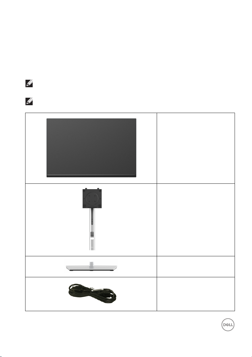
Your monitor ships with the components shown in the table below. If any
component is missing, contact Dell technical support. For more information, see
Contact Dell.
NOTE: Some items may be optional and may not ship with your monitor.
Some features may not be available in certain countries.
NOTE: If you are attaching a stand that you purchased from any other
source, follow the setup instructions available with the stand.
Display
Stand riser
Stand base
Power cable (varies by
country)
About your monitor │ 7
Page 8
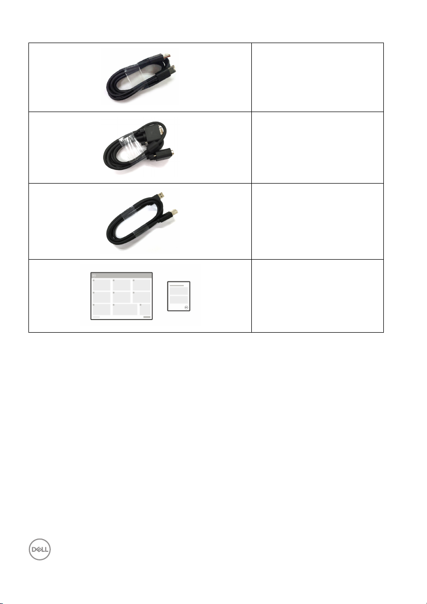
DisplayPort 1.2 cable
(DisplayPort to DisplayPort,
meters)
1.80
VGA cable (Japan onl y,
1.80 meters)
USB 3.2 Gen1 (5 Gbps)
upstream cable (enables the
USB ports on the monitor,
1.80 meters)
•Quick Setup Guide
• Safety, Environmental,
and R
egulatory
Information
8 │ About your monitor
Page 9

Product features
The Dell P2423 monitor has an active matrix, Thin-Film Transistor (TFT), Liquid
Crystal Display (LCD) and LED backlight. The monitor features include:
• 60.96 cm (24 in.) viewable area (measured diagonall y).
1920 x 1200 (16:10) resolution, plus ful l-screen support for lower resolutions.
• Wide viewing angle to allow viewing from a sitting or standing position.
• Color gamut of 99% sRGB.
• Video connectivity with DVI, DisplayPort, HDMI and VGA.
• Tilt, swivel, height and pivot adjustment capabilities.
• Removable stand and Video Electronics Standards Association (VESA™)
100
mm mounting holes for flexible mounting solutions.
• Equipped with 1 USB Type B upstream port and 4 SuperSpeed USB 5 Gbps
(USB 3.2 Gen1) Type-A downstream ports.
• Plug and play capability if supported by your system.
• On-Screen Display (OSD) adjustments for ease of set-up and screen
optimization.
• Power and joystick buttons lock.
• Security lock slot.
• Stand lock.
• < 0.3 W in Standby Mode.
• Optimize eye comfort with a flicker-free screen and low blue light feature.
• The monitor uses Low Blue Light panel and is in compliance with TUV
Rheinland (Hardware Solution) at factory reset/default setting mode (Preset
mode: Standard).
WARNING: The possible long-term effects of blue light emission from
the monitor may cause damage to the eyes, including eye fatigue,
digital eye strain, and so on. ComfortView Plus feature is designed to
reduce the amount of blue light emitted from the monitor to optimize
eye comfort.
About your monitor │ 9
Page 10
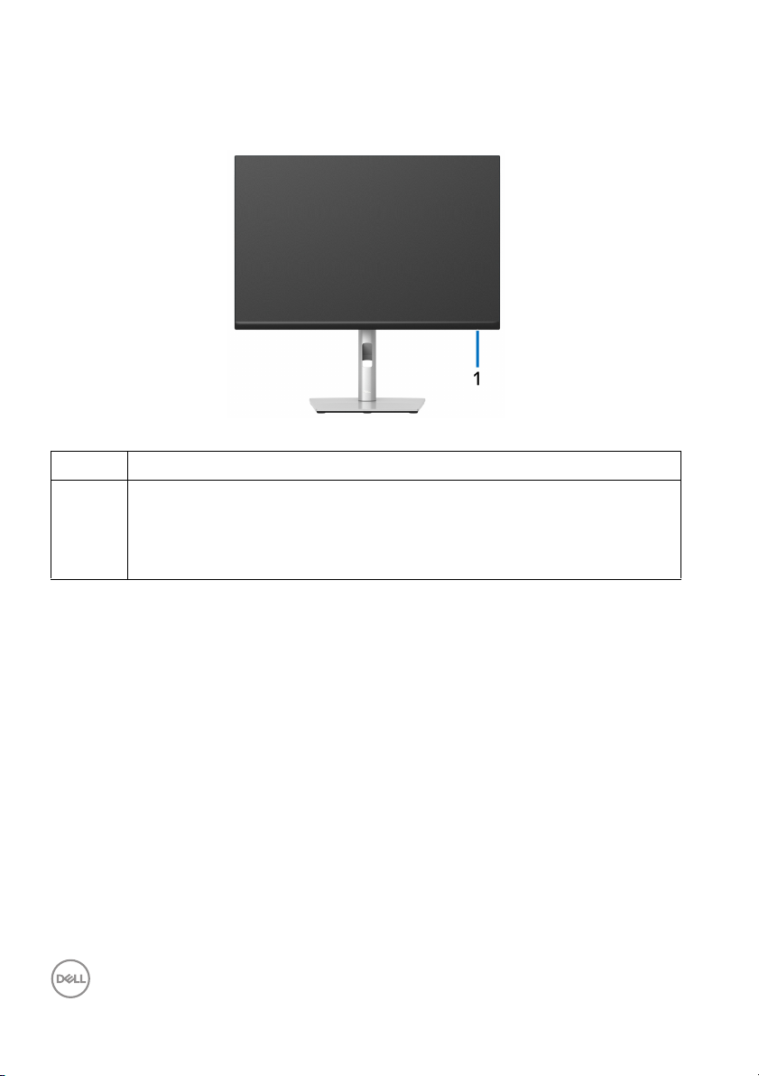
Identifying parts and controls
Front view
Label Description
1 Power LED indicator
Solid white light indicates that the monitor is turned on and functioning
norma
lly. Blinking white light indicates that the monitor is in Standby
Mode.
10 │ About your monitor
Page 11
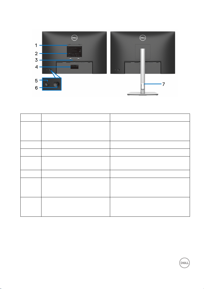
Back view
Back view with monitor stand
Label Description Use
1 VESA mounting holes (100 mm
x 1
00 mm - behind attached
A Cover)
VES
2 Regulatory label Lists the regulatory approvals.
3 Stand release button Releases stand from the monitor.
4 Barcode, serial number, and
Service
5 Power On/Off button To turn the monitor on or off.
6 Joystick Use to control the OSD menu. For
7 Cable-management slot Use to organize cables by inserting
Tag label
Wall-mount the monitor using VESAc
ompatible wall mount kit (100 mm x
0 mm).
10
Refer to this label if you need to
contact Dell for technical support.
mo
re Information, see Operating the
monitor.
them
through the slot. But this does
not accommodate DVI cable.
About your monitor │ 11
Page 12
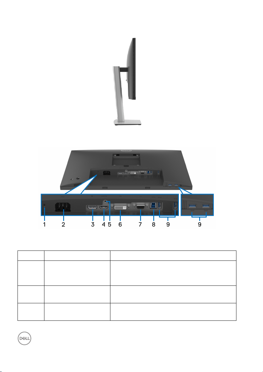
Side view
Bottom view
Bottom view without monitor stand
Label Description Use
1 Security lock slot
(based on
Security Slot™)
2 Power connector Connect the power cable (shipped with your
3 DisplayPort Connect your computer with the DisplayPort
12 │ About your monitor
Kensington
Secures the monitor with a security lock
(security lock not included).
monit
or).
cab
le (shipped with your monitor).
Page 13
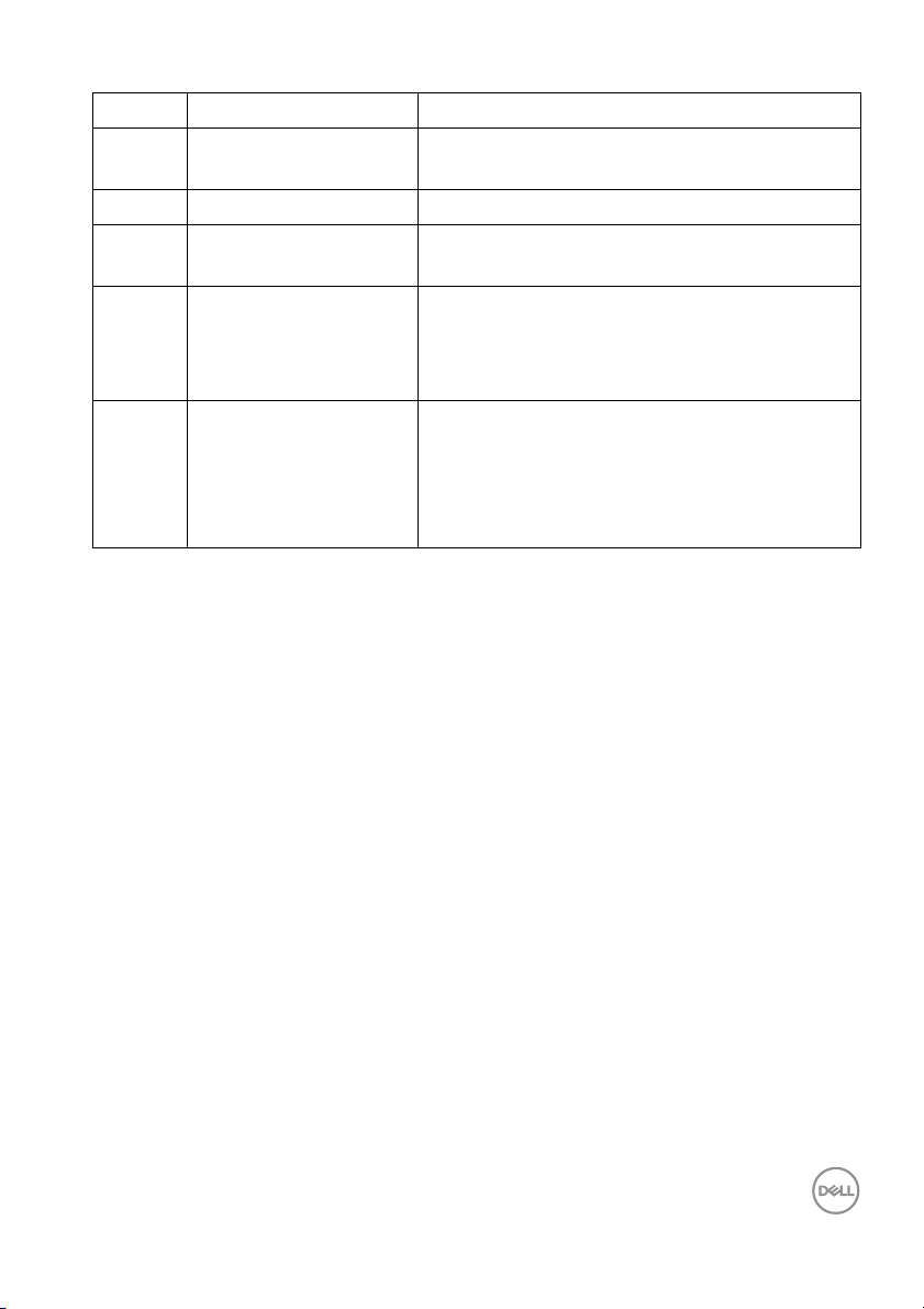
4 HDMI port Connect your computer with the HDMI cable.
5 Stand lock feature To lock the stand to the monitor using a M3 x
6
mm screw (screw not included).
6 DVI port Connect your computer with the DVI cable.
7 VGA connector Connect your computer with the VGA cable
(shipped with your monitor, for Japan only).
8 SuperSpeed USB
5
Gbps (USB 3.2 Gen1)
upstream port
9 SuperSpeed USB
5
Gbps (USB 3.2 Gen1)
downstream port (4)
*To avoid signal interference, when a wireless USB device has been connected to a
USB downstream port, it is NOT recommended to connect any other USB devices
to the adjacent port(s).
Connect the USB cable that came with your
monitor to the computer. Once this cable is
connected, you can use the USB connectors
on the monitor.
Connect your USB 3.2 Gen1 (5 Gbps) device.*
NOTE: To use these ports, you must connect
the USB cable (shipped with your monitor) to
the USB-upstream port on the monitor and to
your computer.
About your monitor │ 13
Page 14
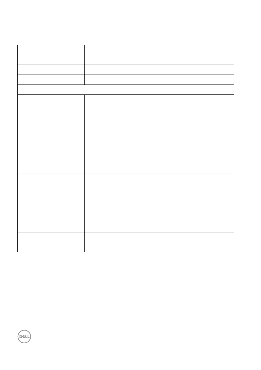
Monitor specifications
Model P2423
Screen type Active matrix - TFT LCD
Panel technology In-Plane Switching Technology
Aspect ratio 16:10
Viewable image
Diagonal
Width (active area)
Height (active area)
Tot a l a re a
Pixel pitch 0.270 mm x 0.270 mm
Pixel per inch (PPI) 94
Viewing angle 178° (vertical) typical
Luminance output 300 cd/m² (typical)
Contrast ratio 1000 to 1 (typical)
Faceplate coating Anti-glare treatment of the polarizer (Haze 25%, 3H)
Backlight White LED edgelight system
Response time 8 ms (Normal mode)
Color depth 16.7 million colors
Color gamut sRGB 99% (typical)
609.60 mm (24 in.)
518.40 mm (20.41 in.)
324.00 mm (12.76 in.)
167961.60 mm2 (260.34 in.2)
178° (horizontal) typical
5 ms (Fast mode)
14 │ About your monitor
Page 15
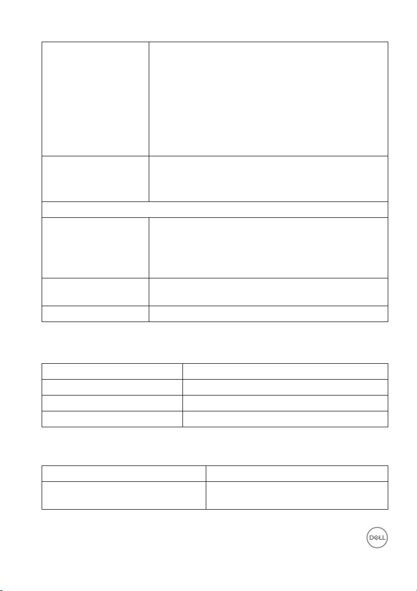
Connectivity • 1 x DisplayPort version 1.2 (HDCP 1.4)
• 1 x HDMI port version 1.4 (HDCP 1.4)
•1 x DVI port
•1 x VGA port
• 1 x SuperSpeed USB 5 Gbps (USB 3.2 Gen1)
upstr
eam port
• 4 x SuperSpeed USB 5 Gbps (USB 3.2 Gen1)
wnstream port
do
Border width (edge of
m
onitor to active area)
Adjustability
Height adjustable stand
Ti l t
Swivel
Pivot
Del l Display Manager
compa
tibility
Security Security lock slot (cable lock sold separately)
6.30 mm (Top)
6.30 mm (Left/Right)
17.80 mm (Bottom)
150 mm
-5° to 21°
-45° to 45°
-90° to 90°
Easy Arrange and other key features
Resolution specifications
Model P2423
Horizontal scan range 30 kHz to 83 kHz (automatic)
Vertica l scan range 56 Hz to 76 Hz (automatic)
Maximum preset resolution 1920 x 1200 at 60 Hz
Supported video modes
Model P2423
Video display capabilities (VGA & DVI
& HDMI
& DisplayPort playback)
480p, 576p, 720p, 1080i, 1080p, FHD
About your monitor │ 15
Page 16
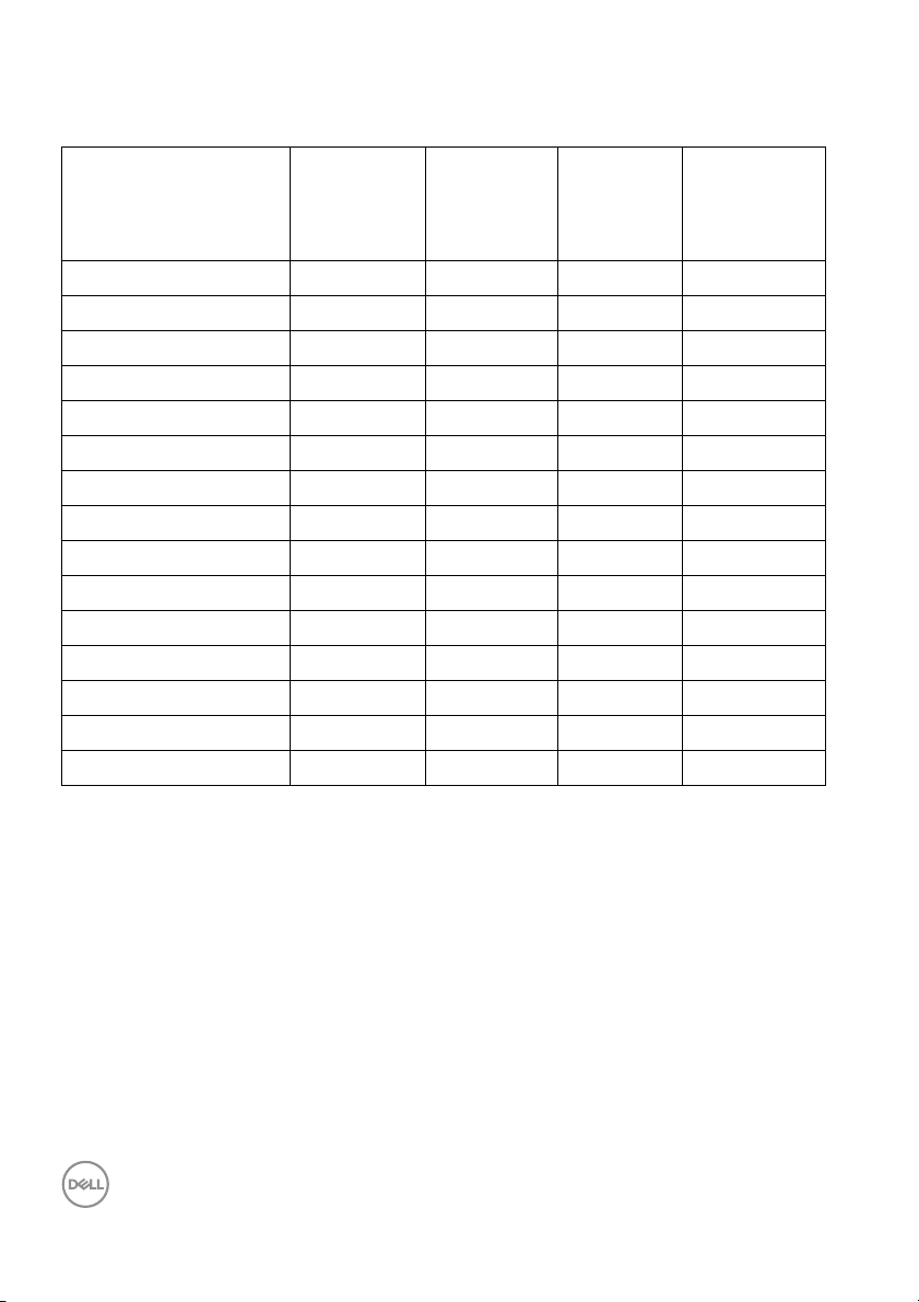
Preset display modes
Display mode Horizontal
frequency
(kHz)
720 x 400 31.50 70.10 28.30 -/+
VESA, 640 x 480 31.50 59.90 25.20 -/-
VESA, 640 x 480 37.50 75.00 31.50 -/-
VESA, 800 x 600 37.90 60.30 40.00 +/+
VESA, 800 x 600 46.90 75.00 49.50 +/+
VESA, 1024 x 768 48.40 60.00 65.00 -/-
VESA, 1024 x 768 60.00 75.00 78.80 +/+
VESA, 1152 x 864 67.50 75.00 108.00 +/+
1280 x 720 45.00 59.90 74.25 -/+
1280 x 720 56.50 74.80 95.75 -/+
VESA, 1280 x 1024 64.00 60.00 108.00 +/+
VESA, 1280 x 1024 80.00 75.00 135.00 +/+
VESA, 1600 x 1200 75.00 60.00 162.00 +/+
VESA, 1920 x 1080 67.50 60.00 148.50 +/+
1920 x 1200 74.00 60.00 154.00 +/+
Vertical
frequency
(Hz)
Pixel
clock
(MHz)
Sync
polarity
(Horizontal
/Vertical)
16 │ About your monitor
Page 17
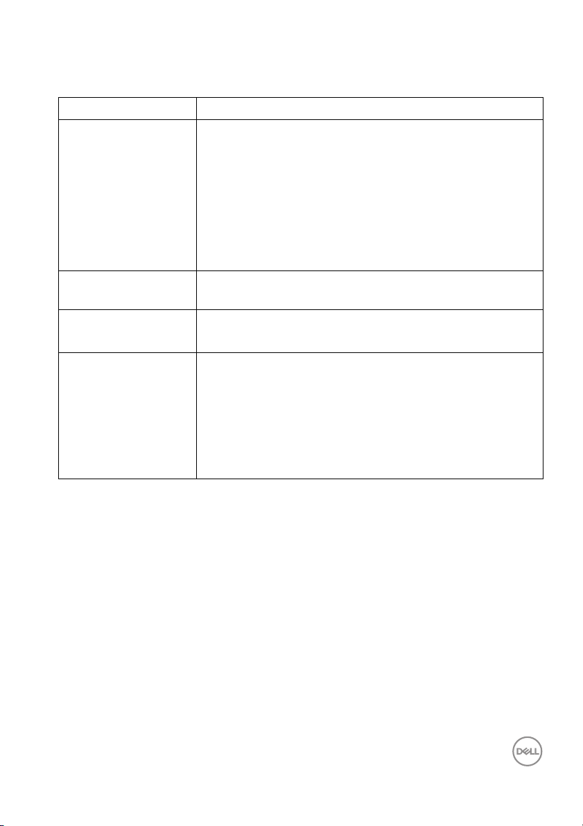
Electrical specifications
Model P2423
Video input signals • Analog RGB, 0.7 V ± 5%, positive polarity at 75 Ω input
imp
edance
• Digital DVI-D TMDS, 600 mV for each differential line,
e polarity at 50 Ω input impedance
positiv
• HDMI 1.4, 600 mV for each differential line, 100 Ω input
edance per differential pair
imp
• DisplayPort 1.2, 600 mV for each differential line, 100 Ω
nput impedance per differential pair
i
AC input vo l tage/
fr
equency/current
100 VAC to 240 VAC / 50 Hz or 60 Hz ± 3 Hz / 1.5 A
Inrush current •120 V: 30 A (Max.) at 0°C (cold start)
•240 V: 60 A (Max.) at 0°C (cold start)
Power consumption • 0.2 W (Off mode)
•0.3 W (Standby Mode)
• 14.8 W (On mode)
•48 W (Max.)
•12.85 W (Pon)
•40.76 kWh (TEC)
1
1
1
2
3
3
1
As defined in EU 2019/2021 and EU 2019/2013.
2
Max brightness and contrast setting with maximum power loading on all USB
ports.
3
Pon: Power consumption of On mode as defined in Energy Star 8.0 version.
TEC: Total energy consumption in kWh as defined in Energy Star 8.0 version.
This document is informational only and reflects laboratory performance. Your
product may perform differently, depending on the software, components and
peripherals you ordered and shall have no obligation to update such information.
Accordingly, the customer should not rely upon this information in making
decisions about electrical tolerances or otherwise. No warranty as to accuracy or
completeness is expressed or implied.
About your monitor │ 17
Page 18
NOTE: This monitor is ENERGY STAR certified.
This product qualifies for ENERGY STAR in the factory
lt settings which can be restored by “Factory Reset”
defau
function in the OSD menu. Changing the factory default
settings or enabling other features may increase power
consumption that could exceed the ENERGY STAR specified
limit.
Physical characteristics
Model P2423
Signal cable type • Digital: DisplayPort, 20 pins
• Digital: HDMI, 19 pins (cable not included)
• Digital: DVI-D, 24 pins (cable not
inc
luded)
• Analog: D-Sub, 15 pins (cable not
ncluded, except for Japan)
i
• Universal Serial Bus: USB, 9 pins
NOTE: De
are shipped with your monitor. As Dell does not have control over the different
cable suppliers in the market, the type of material, connector and process used to
manufacture these cables, Dell does not guarantee video performance on cables
that are not shipped with your Dell monitor.
Dimensions (with stand)
Height (extended) 510.80 mm (20.11 in.)
Height (compressed) 364.00 mm (14.33 in.)
Width 531.00 mm (20.90 in.)
Depth 179.57 mm (7.07 in.)
Dimensions (without stand)
Height 348.10 mm
Width 531.00 mm (20.90 in.)
Depth 53.26 mm (2.10 in.
ll monitors are designed to work optimally with the video cables that
(13.70 in.)
)
18 │ About your monitor
Page 19
Stand dimensions
Height (extended) 410.80 mm (16.17 in.)
Height (compressed) 364.00 mm (14.33 in.)
Width 245.00 mm (9.65 in.)
Depth 179.57 mm (7.07 in.)
Base 245.00 mm x 173.00 mm (9.65 in. x 6.81 in.)
Weight
Weight with packaging 7.7 1 kg ( 1 7. 0 0 l b)
Weight with stand assembl y and
cables
Weight without stand assembly
(For wall mount or VESA mount
considerations - no cables)
Weight of stand assembly 1.71 kg (3.77 lb)
Front frame gloss Black frame 2-4 gloss units
5.56 kg (12.26 l b)
3.52 kg (7.76 lb)
About your monitor │ 19
Page 20
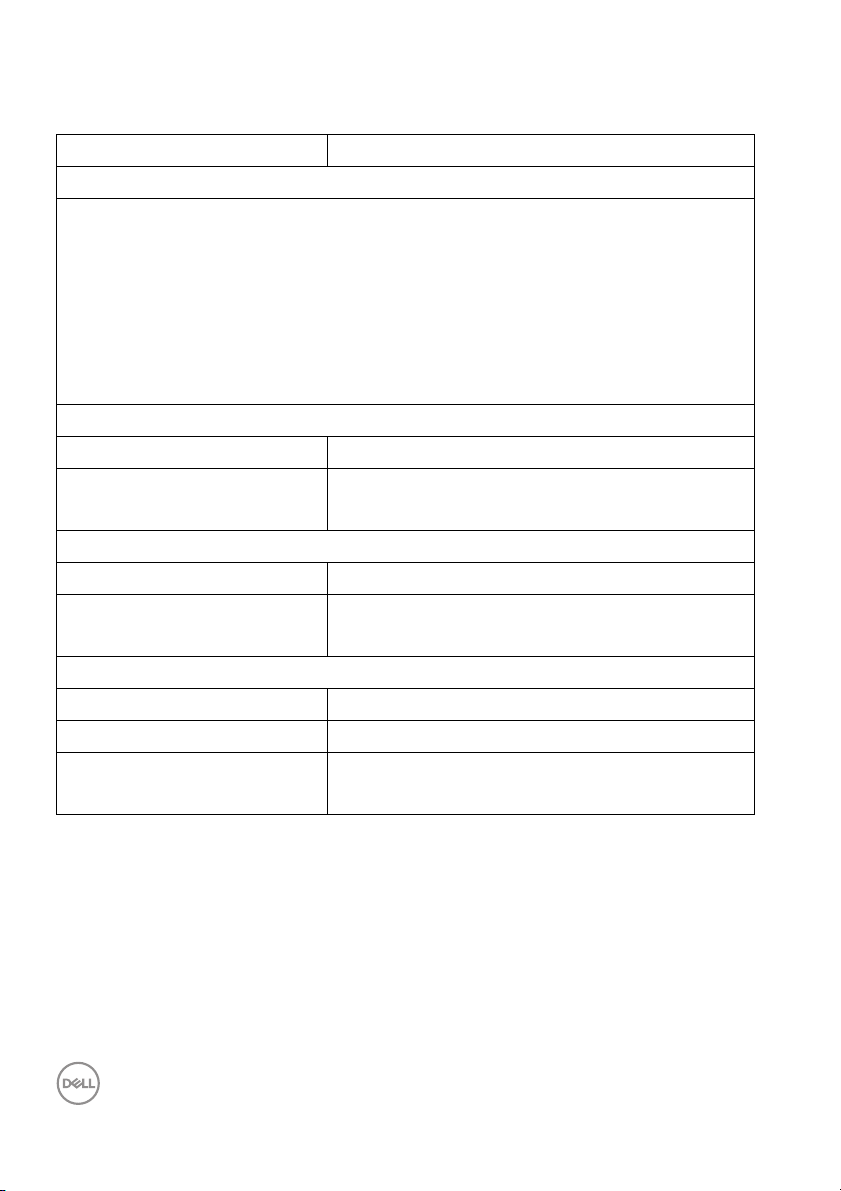
Environmental characteristics
Model P2423
Compliant standards
• ENERGY STAR certified monitor
• EPEAT registered where applicable. EPEAT registration varies by country. See
www.epeat.net for registration status by country.
• RoHS-compliant
• TCO Certified & TCO Certified Edge
• BFR/PVC Free monitor (excluding external cables)
• Arsenic-free glass and Mercury-free for the panel only
Te m p er at u r e
Operating 0°C to 40°C (32°F to 104°F)
Non-operating • Storage: -20°C to 60°C (-4°F to 140°F)
• Shipping: -20°C to 60°C (-4°F to 140°F)
Humidity
Operating 10% to 80% (non-condensing)
Non-operating • Storage: 5% to 90% (non-condensing)
• Shipping: 5% to 90% (non-condensing)
Altitude
Operating 5000 m (16404 ft) (maximum)
Non-operating 12192 m (40000 ft) (maximum)
Thermal dissipation • 163.78 BTU/hour (maximum)
•54.59 BTU/hour (typical)
20 │ About your monitor
Page 21
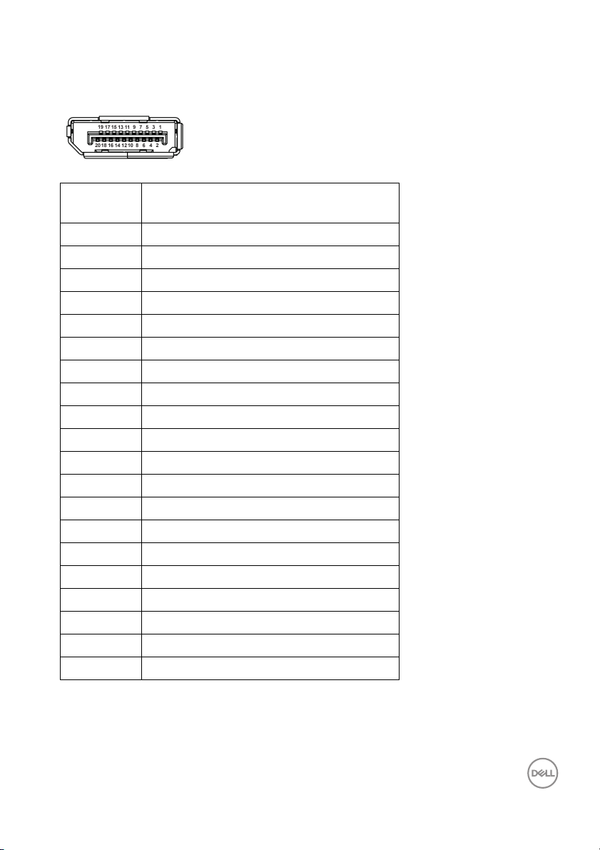
Pin assignments
DisplayPort connector
Pin
number
1 ML3 (n)
2 GND
3 ML3 (p)
4 ML2 (n)
5 GND
6 ML2 (p)
7 ML1 (n)
8 GND
9 ML1 (p)
10 ML0 (n)
11 GND
12 ML0 (p)
13 GND
14 GND
15 AUX (p)
16 GND
17 AUX (n)
18 Hot Plug Detect
19 Re-PWR
20 +3.3 V DP_PWR
20-pin side of the connected signal
cable
About your monitor │ 21
Page 22
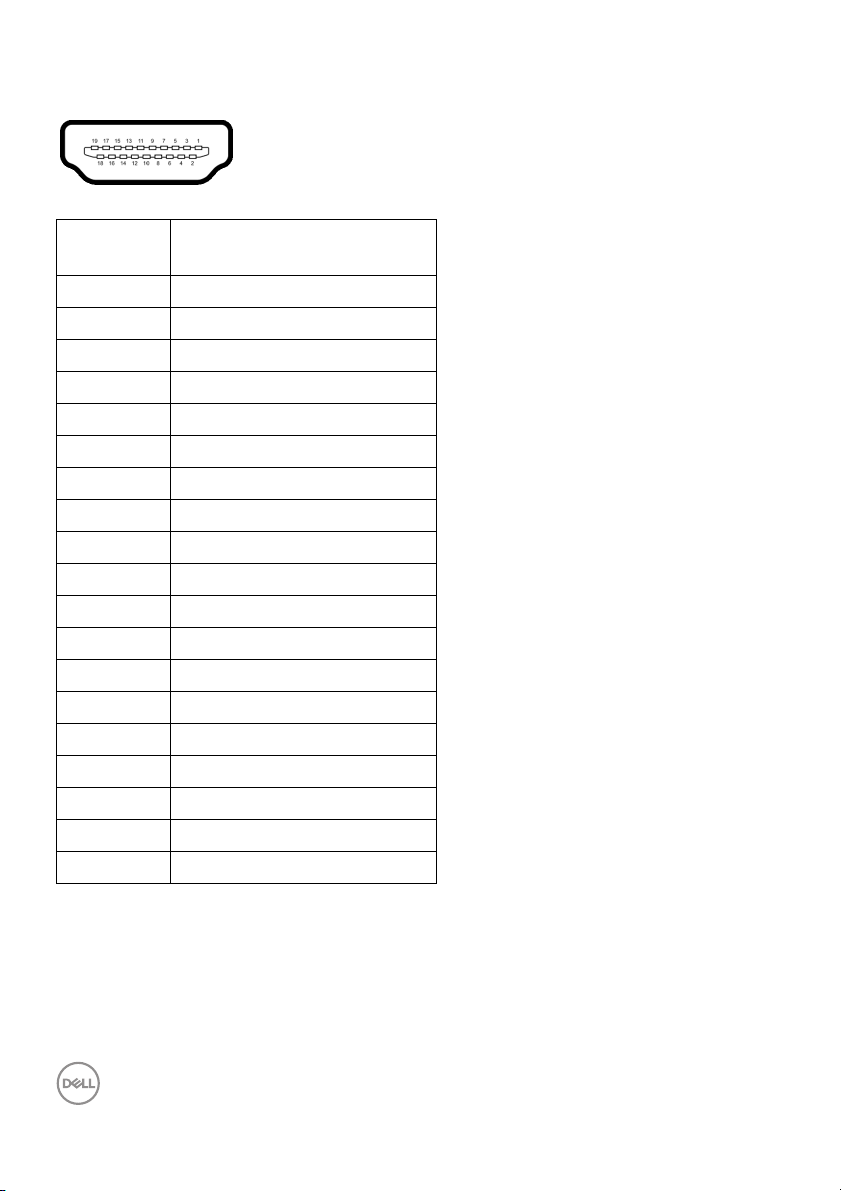
HDMI connector
Pin
number
1 TMDS DATA 2+
2 TMDS DATA 2 SHIELD
3 TMDS DATA 2-
4 TMDS DATA 1+
5 TMDS DATA 1 SHIELD
6 TMDS DATA 1-
7 TMDS DATA 0+
8 TMDS DATA 0 SHIELD
9 TMDS DATA 0-
10 TMDS CLOCK+
11 TMDS CLOCK SHIELD
12 TMDS CLOCK-
13 CEC
14 Reserved (N.C. on device)
15 DDC CLOCK (SCL)
16 DDC DATA (SDA)
17 DDC/CEC Ground
18 +5 V POWER
19 HOT PLUG DETECT
19-pin side of the
connected signal cable
22 │ About your monitor
Page 23
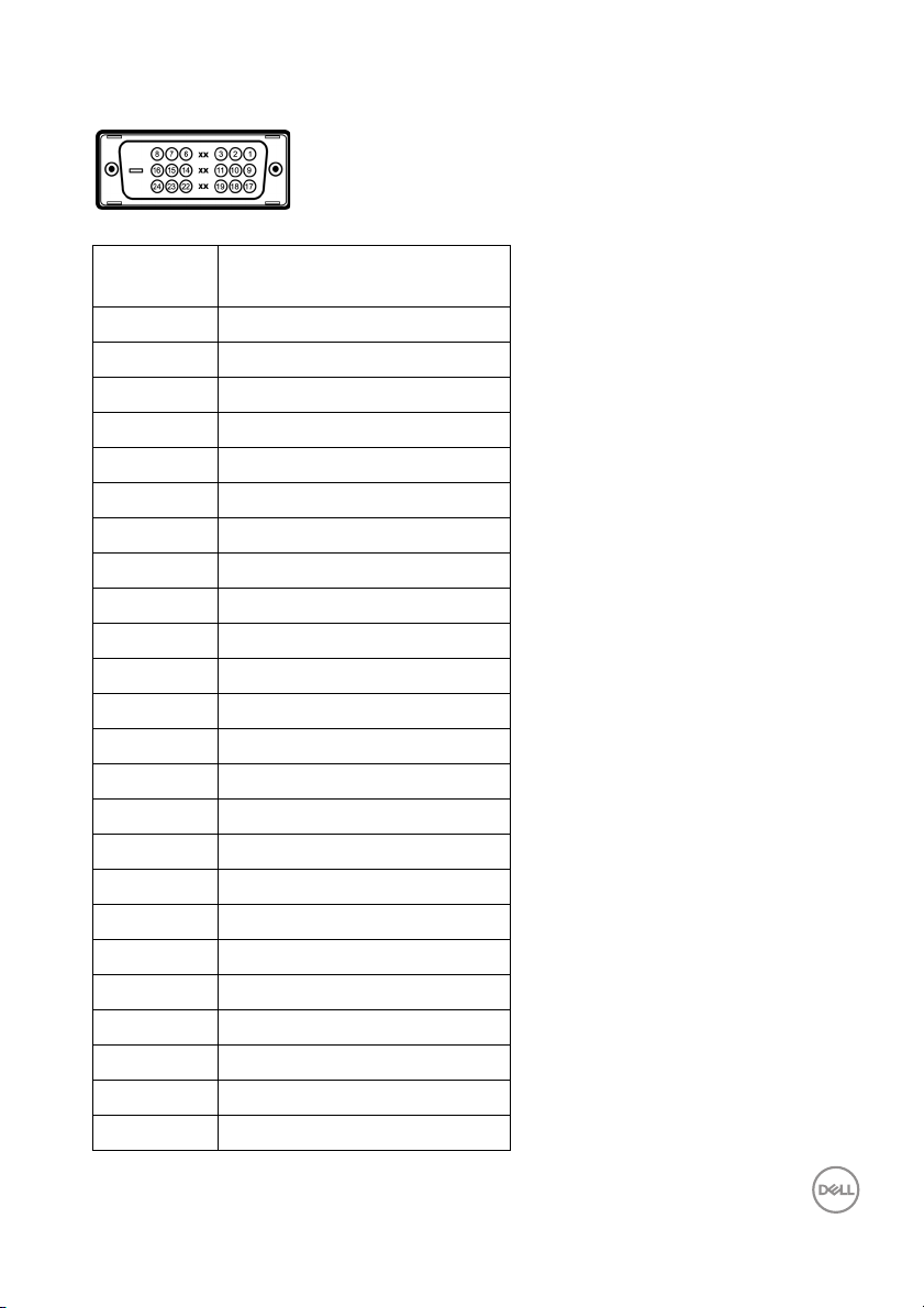
DVI connector
Pin
number
1 TMDS RX2-
2 TMDS RX2+
3 TMDS Ground
4 Floating
5 Floating
6 DDC Clock
7 DDC Data
8 Floating
9 TMDS RX1-
10 TMDS RX1+
11 TMDS Ground
12 Floating
13 Floating
14 +5 V/+3.3 V power
15 Sel f test
16 Hot Plug Detect
17 TMDS RX0-
18 TMDS RX0+
19 TMDS Ground
20 Floating
21 Floating
22 TMDS Ground
23 TMDS Clock+
24 TMDS Clock-
24-pin side of the
connected signal cable
About your monitor │ 23
Page 24
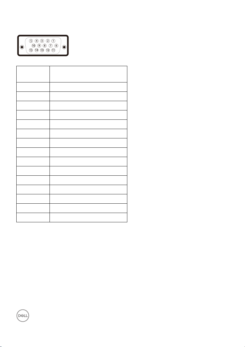
VGA connector
Pin
number
1 Video-Red
2 Video-Green
3 Video-Blue
4 GND
5 Self-test
6 GND-R
7 GND-G
8 GND-B
9 Computer 5 V/3.3 V
10 GND-sync
11 GND
12 DDC data
13 H-sync
14 V-sync
15 DDC clock
15-pin side of the
connected signal cable
Plug and play capability
You can install the monitor in any Plug and Play-compatible system. The monitor
automatically provides the computer system with its Extended Display Identification
Data (EDID) using Display Data Channel (DDC) protocols so that the system can
configure itself and optimize the monitor settings. Most monitor installations are
automatic; you can select different settings if desired. For more information about
changing the monitor settings, see Operating the monitor.
24 │ About your monitor
Page 25
Universal Serial Bus (USB) interface
This section gives you information about the USB ports that are available on the
monitor.
SuperSpeed USB 5 Gbps (USB 3.2 Gen1)
Transfer speed Data rate Maximum power supported
Super-Speed 5 Gbps 5 V/0.9 A (Max, each port)
High speed 480 Mbps 5 V/0.9 A (Max, each port)
Full speed 12 Mbps 5 V/0.9 A (Max, each port)
NOTE: This monitor is SuperSpeed USB 5 Gbps (USB 3.2 Gen1)
compatible.
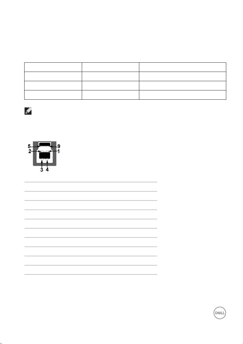
USB 3.2 Gen1 (5 Gbps) upstream connector
Pin number 9-pin side of the connector
1 VCC
2 D-
3 D+
4 GND
5 SSTX-
6 SSTX+
7 GND
8 SSRX-
9 SSRX+
About your monitor │ 25
Page 26
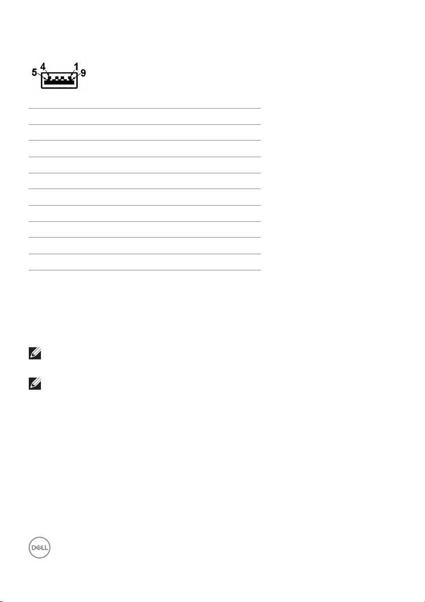
USB 3.2 Gen1 (5 Gbps) downstream connector
Pin number 9-pin side of the connector
1 VCC
2 D-
3 D+
4 GND
5 SSRX-
6 SSRX+
7 GND
8 SSTX-
9 SSTX+
USB ports
• 1 USB Type-B upstream - rear
• 2 USB Type-A downstream - rear
• 2 USB Type-A downstream - bottom
NOTE: USB 3.2 Gen1 (5 Gbps) functionality requires a USB 3.2 Gen1capable computer.
NOTE: The USB ports on the monitor work only when the monitor is
turned On or in Standby mode. If you turn Off the monitor and then
turn it On, the attached peripherals may take a few seconds to resume
normal functionality.
26 │ About your monitor
Page 27
LCD monitor quality and pixel policy
During the LCD Monitor manufacturing process, it is not uncommon for one or more
pixels to become fixed in an unchanging state which are hard to see and do not
affect the display quality or usability. For more information on Dell Monitor Quality
and Pixel Policy, see
www.del l.com/pixelguidelines.
Ergonomics
CAUTION: Improper or prolonged usage of keyboard may resul t in
injury.
CAUTION: Viewing the monitor screen for extended periods of time
may result in eye strain.
For comfort and efficiency, observe the following guidelines when setting up and
using your computer workstation:
• Position your computer so that the monitor and keyboard are directly in front
of you as you work. Special shel ves are commercially available to help you
correctly position your keyboard.
• To reduce the risk of eye strain and neck/arm/back/shoulder pain from using
the monitor for long periods of time, we suggest you to:
1. Set the distance of the screen between 20 to 28 in. (50 - 70 cm) from your
eyes.
2. Blink frequently to moisten your eyes or wet your eyes with water after
prolonged usage of the monitor.
3. Take regular and frequent breaks for 20 minutes every two hours.
4. Look away from your monitor and gaze at a distant object at 20 feet away
for at least 20 seconds during the breaks.
5. Perform stretches to relieve tension in the neck, arm, back, and shoulders
during the breaks.
• Make sure that the monitor screen is at eye level or slightly lower when you
are sitting in front of the monitor.
• Adjust the tilt of the monitor, its contrast, and brightness settings.
• Adjust the ambient lighting around you (such as overhead lights, desk lamps,
and the curtains or blinds on nearby windows) to minimize reflections and
glare on the monitor screen.
• Use a chair that provides good lower-back support.
• Keep your forearms horizontal with your wrists in a neutral, comfortable
position while using the keyboard or mouse.
About your monitor │ 27
Page 28
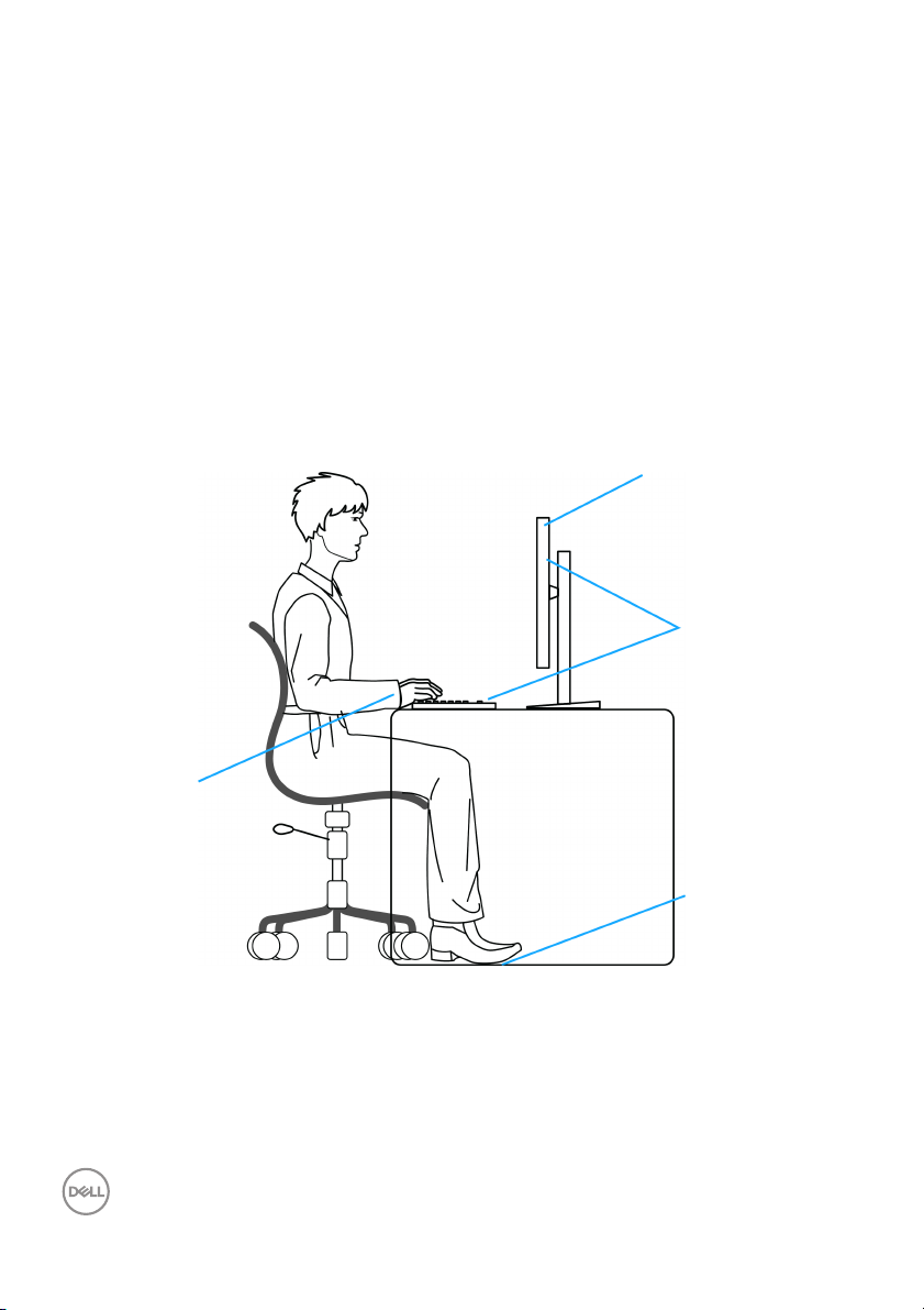
• Always leave space to rest your hands while using the keyboard or mouse.
monitor screen at or
below eye level
monitor and
keyboard
positioned
directly in front
of the user
feet flat on the
floor
wrists relaxed
and flat
• Let your upper arms rest natural ly on both sides.
• Ensure that your feet are resting flat on the floor.
• When sitting, make sure that the weight of your legs is on your feet and not on
the
front portion of your seat. Adjust your chair's height or use a footrest if
necessary to maintain a proper posture.
• Vary your work activities. Try to organize your work so that you do not have to
and work for extended periods of time. Try to stand or get up and walk
sit
around at regular intervals.
• Keep the area under your desk clear of obstructions and cables or power
ds that may interfere with comfortable seating or present a potential trip
cor
hazard.
28 │ About your monitor
Page 29
Handling and moving your display
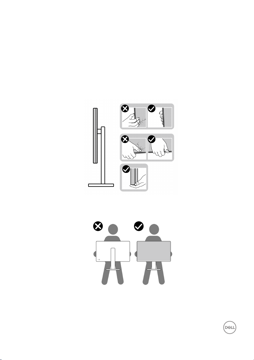
To ensure the monitor is handled safely when lifting or moving it, follow the
guidelines mentioned below:
• Before moving or lifting the monitor, turn off your computer and the monitor.
• Disconnect al l cables from the monitor.
• Place the monitor in the original box with the original packing materials.
• Hold the bottom edge and the side of the monit
excessive pressure when lifting or moving the monitor.
• When lifting or moving the monitor, ensure the screen is facing away from you
and do not press on the display area to avoid any scratches or damage.
or firmly without appl ying
• When transporting the monitor, avoid any sudden shock or vibration to it.
About your monitor │ 29
Page 30
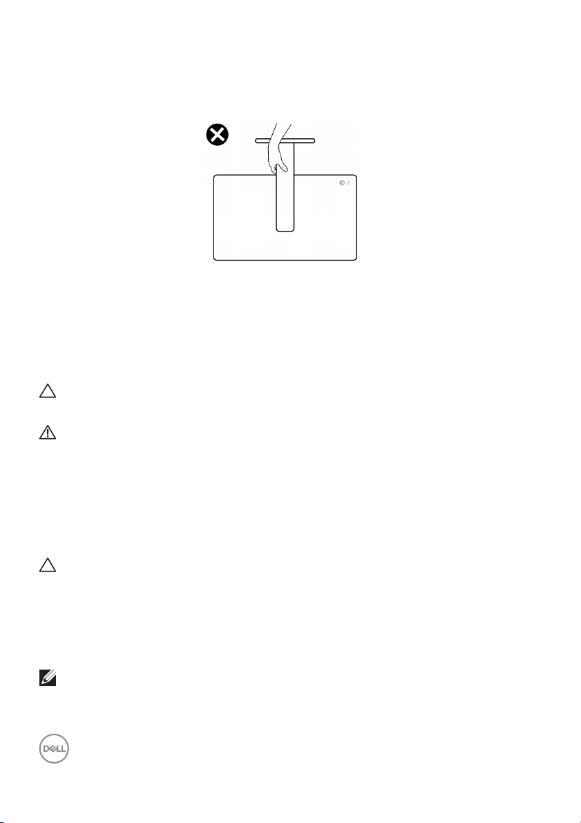
• When lifting or moving the monitor, do not turn the monitor upside down while
holding the stand base or stand riser. This may result in accidental damage to
the monitor or cause personal injury.
Maintenance guidelines
Cleaning your monitor
Improper cleaning methods can result in physical damage to Dell monitors. Physical
de
fects may affect the screen and body of the monitor.
CAUTION: Read and follow the Sa
monitor.
WARNING: Before cleaning the monitor, unplug the monitor power
cable from the electrical outlet.
For best practices, follow the instructions
cleaning, or handling your monitor:
• To clean the Del l Monitor screen, lightly dampen a soft, clean cloth with
ater. If possible, use a special screen-cleaning tissue or solution suitable for
w
the Del l Monitor screen.
CAUTION: Do not use detergents of any kind or other chemicals such as
ene, thinner, ammonia, abrasive cleaners, or compressed air.
benz
not directly spray the cleaning solution or even water on the
• Do
surface of the monitor. Directly spraying liquid onto the panel wil l roll down
to the bottom of the panel and corrode the electronics resulting in permanent
damage. Instead, apply solution or water to soft cloth material.
NOTE: Using cleaner may cause changes in the appearance of the
monitor, such as color fading, milky film on the monitor, deformation,
uneven dark shade, and screen surface peeling.
fety instructions before cleaning the
in the list below when unpacking,
30 │ About your monitor
Page 31

NOTE: Monitor damage due to improper cleaning methods and the use
of benzene, thinner, ammonia, abrasive cleaners, alcohol, compressed
air, detergent of any kind will lead to a Customer Induced Damage
(CID). CID is not covered under the standard Dell warranty.
• If you notice white powder when you unpack your monitor, wipe it off with a
cloth.
• Handle your monitor with care as a darker-colored monitor may get scratched
and show white scuff marks more than a lighter-colored monitor.
• To help maintain the best image quality on your monitor, use a dynamical ly
changing screen saver and turn off your monitor when not in use.
About your monitor │ 31
Page 32
Setting up the monitor
Attaching the stand
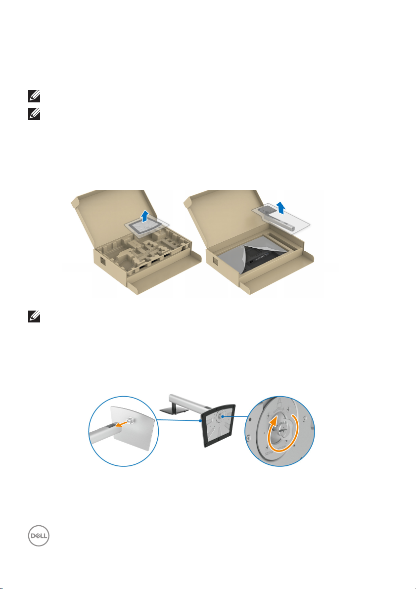
NOTE: The stand is not installed at the factory when shipped.
NOTE: The following instructions are applicable only for attaching the
stand that was shipped with your monitor. If you are attaching a stand
that you purchased from any other source, follow the setup
instructions available with the stand.
To attach the monitor stand:
emove the stand base and stand riser from the packaging cushion.
1. R
NOTE: The graphics are used for the purpose of illustration only. The
appearance of the package cushion may vary.
nsert the stand base blocks fully into the stand slot.
2. I
3. L
ift the screw handle and turn the screw clockwise.
4. A
fter fully tightening the screw, fold the screw handle flat within the recess.
32 │ Setting up the monitor
Page 33
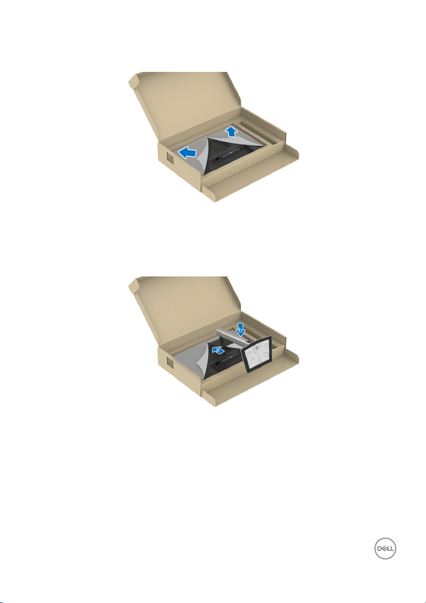
5. Lift the protective cover, as shown, to access the VESA area for stand
assembl y.
6. Attach the stand assembly to the display.
a. Fit the two tabs on the upper part of the stand to the groove on the back of
the display.
b. Press the stand down til l it snaps into place.
Setting up the monitor │ 33
Page 34
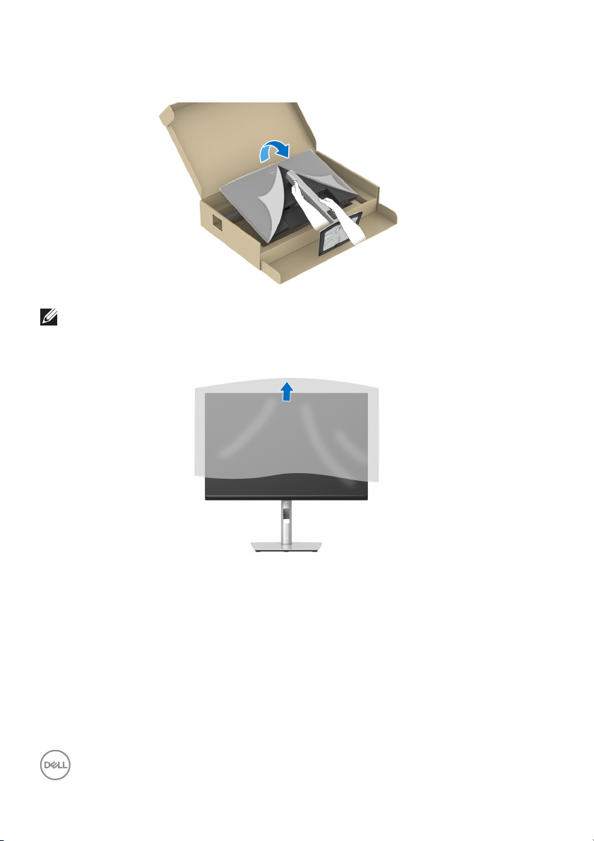
7. Hold the stand riser and lift the monitor carefully, then place it on a flat
surface.
NOTE: Lift the monitor carefully to prevent it from slipping or falling.
8. R
emove the protective cover from the monitor.
34 │ Setting up the monitor
Page 35
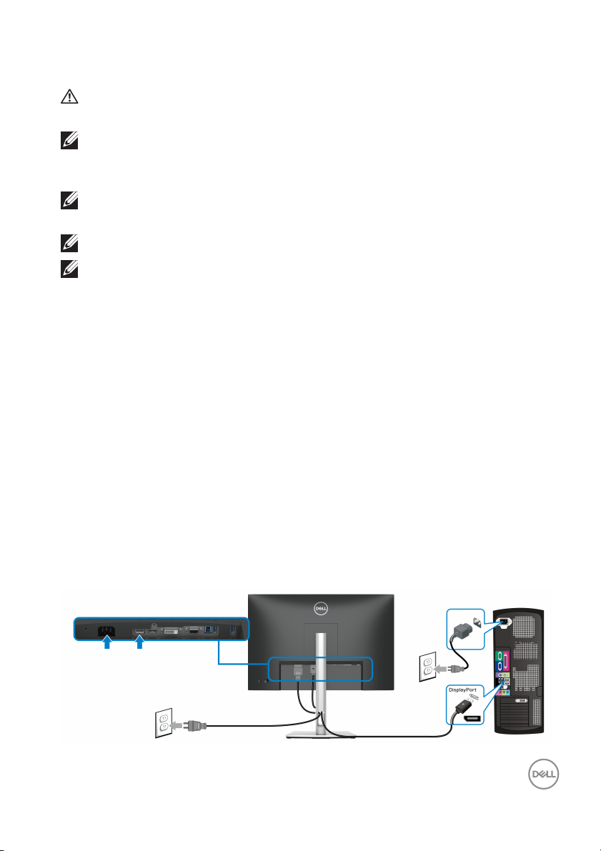
Connecting your monitor
WARNING: Before you begin any of the procedures in this section,
fol low the Safety instructions.
NOTE: Dell monitors are designed to work optimally with Dell supplied
inbox cables. Dell does
when using non-Dell cables.
NOTE: Route the cables through the cable-management slot before
connecting them.
NOTE: Do not connect all cables to the computer at the same time.
NOTE: The graphics are used for the purpose of illustration only. The
appearance of the computer may vary.
To connect your monitor to the computer:
urn Off your computer and disconnect the power cable.
1. T
2. Conne
3. Conne
4. Conne
5. Pl
6. T
ct the DisplayPort, HDMI, VGA or DVI cable from your monitor to the
computer.
ct the USB 3.2 Gen1 upstream port on the monitor and an appropriate
USB 3.2 Gen1 port on your computer with the supplied USB cable (see
Bottom view for details).
ct the USB 3.2 Gen1 peripherals to the USB 3.2 Gen1 downstream ports
on the monitor.
ug the power cables for your computer and monitor into a nearby outlet.
urn On the monitor and the computer.
If your monitor displays an image, installation is
an image, see Common problems.
not guarantee the video quality and performance
complete. If it does not display
Connecting the DisplayPort (DisplayPort to DisplayPort) cable
Setting up the monitor │ 35
Page 36
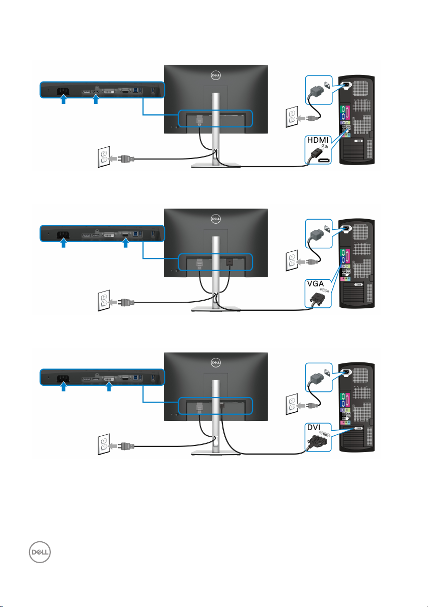
Connecting the HDMI cable (optional)
Connecting the VGA cable (optional)
Connecting the DVI cable (optional)
36 │ Setting up the monitor
Page 37
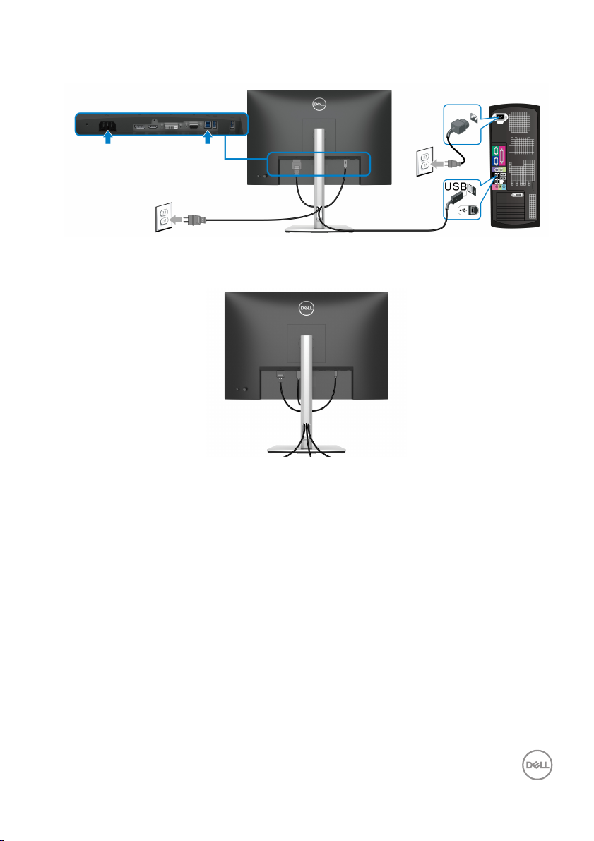
Connecting the USB 3.2 Gen1 (5 Gbps) cable
Organizing your cables
After attaching all the necessary cables to your monitor and computer (see
Connecting your monitor for cable attachment), organize the cables as shown
above.
Setting up the monitor │ 37
Page 38
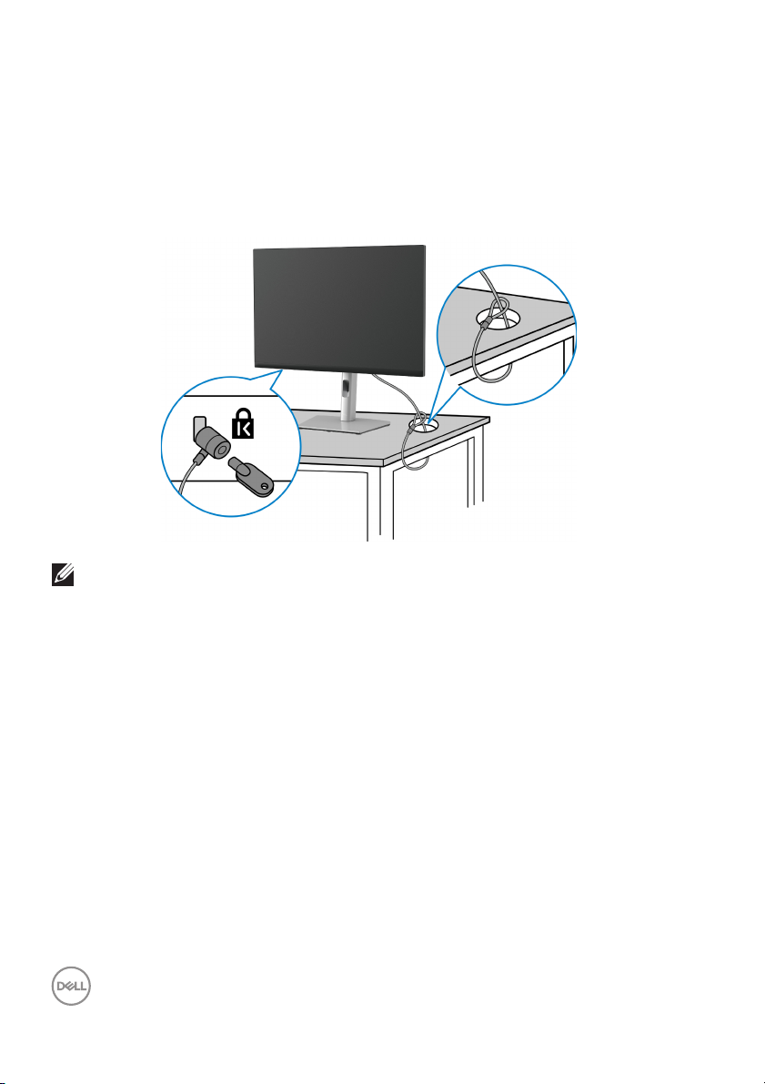
Securing your monitor using Kensington lock (optional)
The security lock slot is located at the bottom of the monitor (see Security lock
slot (based on Kensington Security Slot™)). Secure your monitor to a table using
the Kensington security lock.
For more information on using the
documentation that is shipped with the lock.
NOTE: The image is for the purpose of illustration only. The appearance
of the lock may vary.
Kensington lock (sold separately), see the
38 │ Setting up the monitor
Page 39
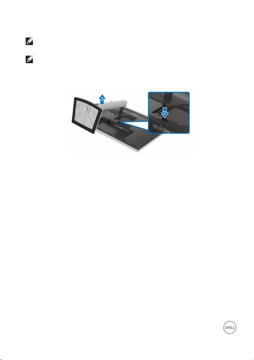
Removing the monitor stand
NOTE: To prevent scratches on the LCD screen when removing the
stand, ensure that the monitor is placed on a soft, clean surface.
NOTE: The following instructions are applicable only for removing the
stand that was shipped with your monitor. If you are removing a stand
that you purchased from any other source, follow the setup
instructions available with the stand.
To remove the stand:
ace the monitor on a soft cloth or cushion.
1. Pl
2. Pr
ess and hold the stand release button.
3. L
ift the stand up and away from the monitor.
Setting up the monitor │ 39
Page 40
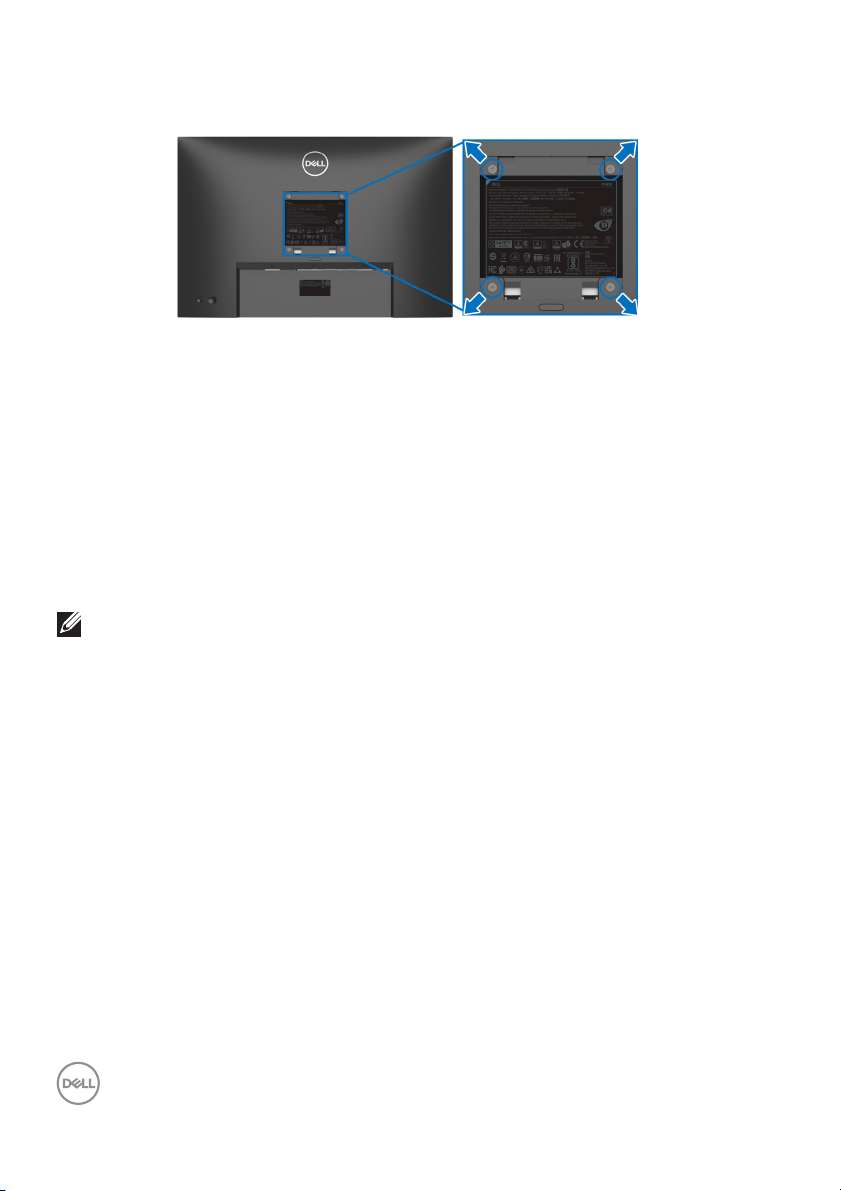
VESA wall mounting (optional)
(Screw dimension: M4 x 10 mm)
Refer to the instructions that come wit
1. Pl
ace the monitor panel on a soft cloth or cushion on a stable flat table.
2. R
emove the stand (see Removing the monitor stand.)
3. Use
4. A
5. Mo
a Phillips crosshead screwdriver to remove the four screws securing the
plastic cover.
ttach the mounting bracket from the wall mounting kit to the monitor.
unt the monitor on the wall. For more information, see the documentation
that shipped with the wall mounting kit.
NOTE: For use only with UL or CSA or GS-listed wall mount bracket
with minimum weight or load bearing capacity of 14.08 kg.
h the VESA-compatible wall mounting kit.
40 │ Setting up the monitor
Page 41
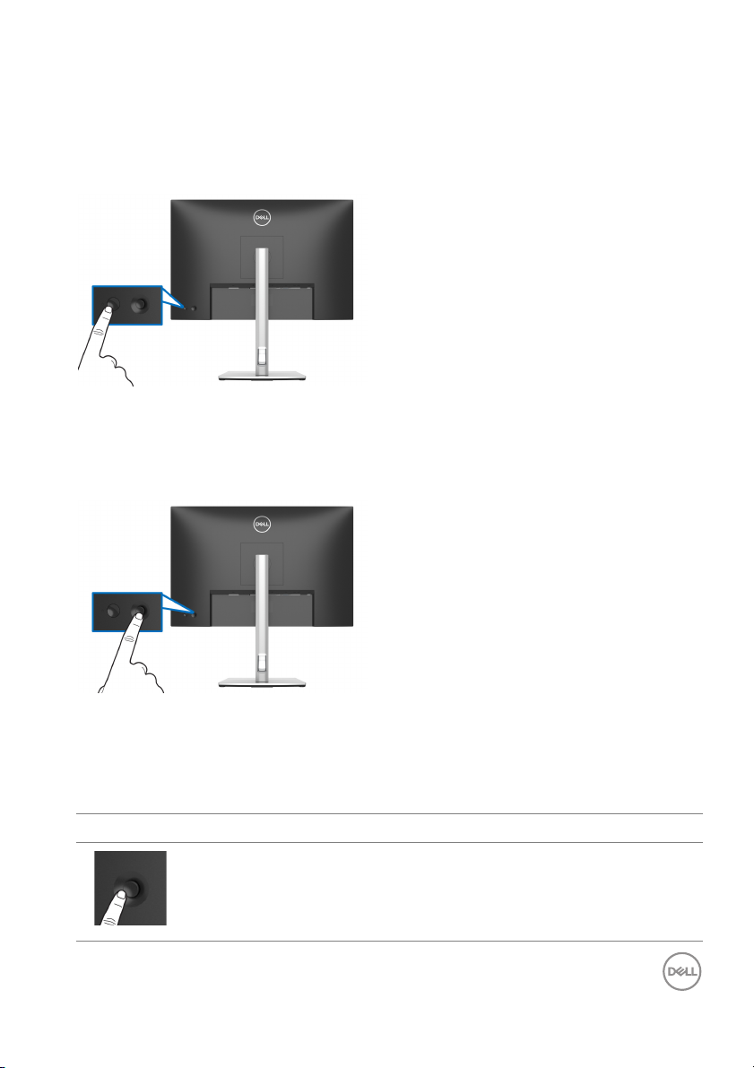
Operating the monitor
Power on the monitor
Press the power button to turn On the monitor.
Using the joystick control
Use the joystick control on the rear of the monitor to make On-Screen Display
(OSD) adjustments.
1. Press the joystick to launch the Menu Launcher.
2. Mo
ve the joystick up/down/left/right to toggle between options.
3. Pr
ess the joystick again to confirm the selection.
Joystick Description
• When there is no OSD on the screen, press the joystick to launch
the Menu Launcher. See Accessing the Menu Launcher.
• When the OSD is displayed, press the joystick to confirm the
lection or save the settings.
se
Operating the monitor │ 41
Page 42
• For 2-way (right and left) directional navigation.
• Move right to enter the submenu.
• Move left to exit from the submenu.
• For 2-way (up and down) directional navigation.
• Toggles between the menu items.
• Increases (up) or decreases (down) the parameters of selected
me
nu item.
Using the On-Screen Display (OSD) menu
Accessing the Menu Launcher
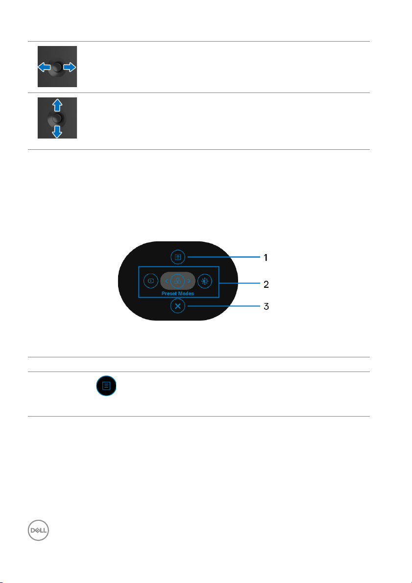
When you move or press the joystick, the Menu
the OSD main menu and shortcut functions,
To select a function, move the joystick.
Launcher appears to let you access
The following table describes the Menu Launcher functions:
Label Icon Description
1
Menu
42 │ Operating the monitor
To launch the On-Screen Display (OSD) main menu.
e Accessing the menu system.
Se
Page 43
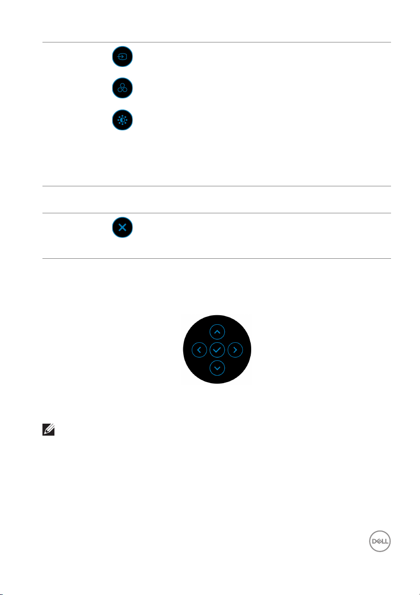
2
Shortcut
functions
NOTE: A
before you proceed to another function or exit.
Using the navigation keys
When the OSD main menu is active, move the joystick to configu
following the navigation keys displayed below the OSD.
fter you adjust the settings, press the joystick to save the changes
3
Exit
When you move the joystick to the left or right to
t
oggle between the shortcut functions, the selected
item will be highlighted and shifted to the center
position. Press the joystick to enter its submenu.
• Input So
list of video signals that may be connected to your
monitor.
• Pr
from the list of preset modes.
• Bri
sliders of brightness and contrast.
To exit the Menu Launcher.
urce: To choose an input source from the
eset Modes: To choose a preferred color mode
ghtness/Contrast: To access the adjustment
re the settings,
After you adjust the settings, press the joystick to save the changes before you
proceed to another menu or exit the OSD menu.
NOTE: To exit the current menu item and return to the previous menu,
move the joystick to the left until you exit.
Operating the monitor │ 43
Page 44
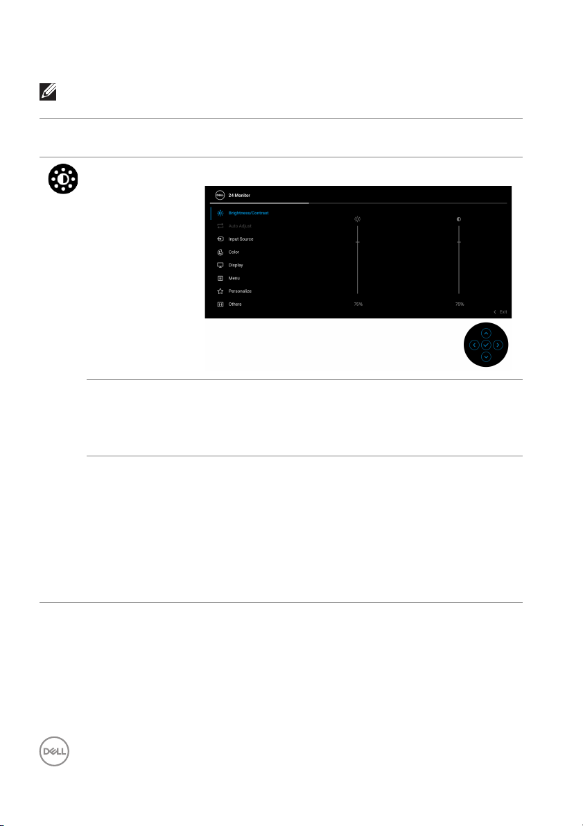
Accessing the menu system
NOTE: After you adjust the settings, press the joystick to save the
changes before you proceed to another menu or exit the OSD menu.
Icon Menu and
Submenus
Brightness/
Contrast
Brightness Brightness adjusts the luminance of the backlight.
Contrast Adjusts the Br
Description
Adjusts the brightness and the contrast of the display.
Move the joystick up to increase the brightness level
o
r move the joystick down to decrease the brightness
level (min. 0 / max. 100).
ightness first, and then adjust the
Contrast only if further adjustment is necessary.
Move the joystick up to increase the contrast level or
ve the joystick down to decrease the contrast level
mo
(min. 0 / max. 100).
The Co
difference between darkness and lightness on the
monitor screen.
ntrast function adjusts the degree of
44 │ Operating the monitor
Page 45
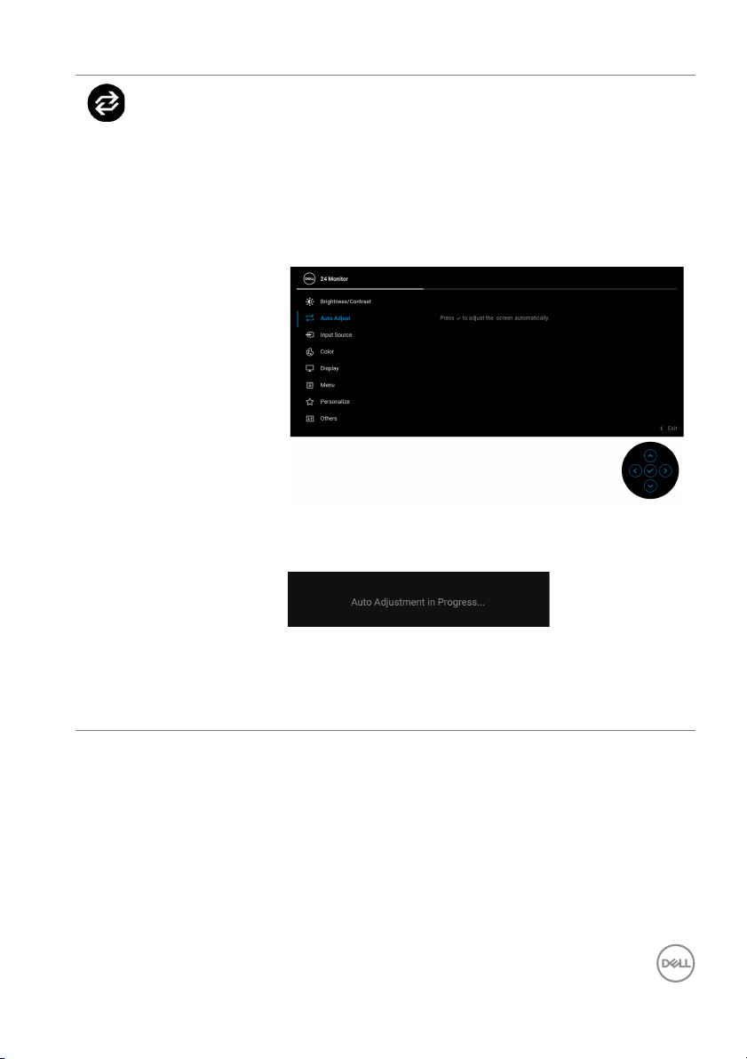
Auto Adjust Even though your computer recognizes your monitor
on startup, the Auto Adjust function optimizes the
display settings for use with your particular setup.
Auto Adjust a
incoming video signal. After using Auto Adjust, you
can further tune your monitor by using the Pixel
Clock (Coarse) and Phase (Fine) controls under
Display settings.
The following dialog appears as the monitor
automatically adjusts to the current input:
llows the monitor to self-adjust to the
NOTE: In most cases, Auto Adjust produces the best
image for your configuration.
NOTE: Auto Adjust is
monitor is connected using the VGA cable.
only available when your
Operating the monitor │ 45
Page 46
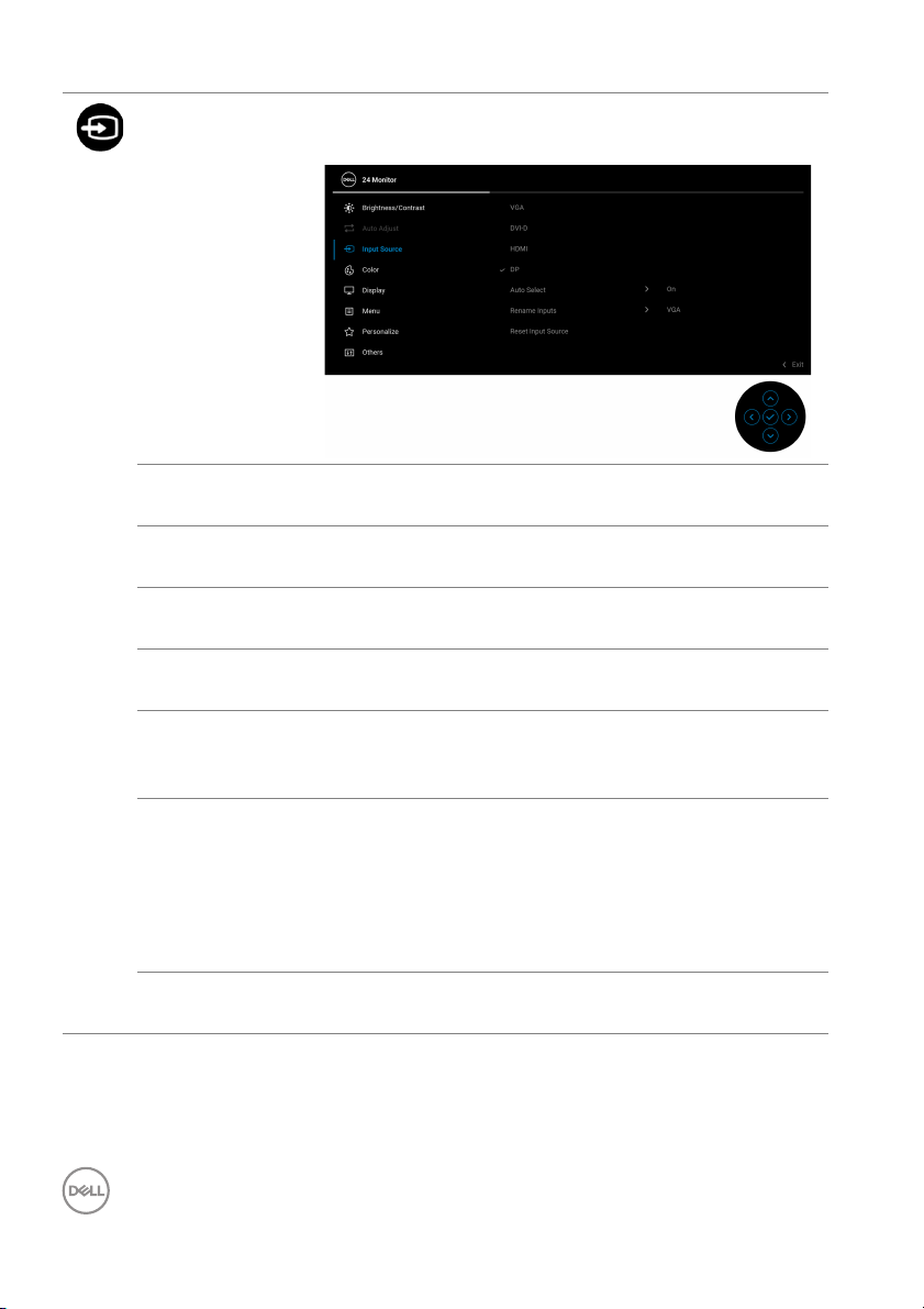
Input Source Use Input Source to select between the different
video signals that may be connected to your monitor.
VGA Select VGA input when you are using the VGA
connector. Press the joystick to confirm the selection.
DVI-D Select DV
connector. Press the joystick to confirm the selection.
HDMI Select HDM
connector. Press the joystick to confirm the selection.
DP Select DP
connector. Press the joystick to confirm the selection.
Auto Select Automatically scans for available input
default is On. Press the joystick to confirm the
selection.
Rename Inputs Allows you to specify a preset input name for the
se
lected input source. The preset options are PC,
PC 1, PC 2, La
default setting is Off.
NOTE: Th
messages and Display Info will not be changed.
Reset Input
Sour
ce
Resets your monitor input settings to the factory
settings.
I-D input when you are using the DVI-D
I when you are using the HDMI
when you are using the DisplayPort (DP)
sources. The
ptop, Laptop 1, and Laptop 2. The
e input names shown in the warning
46 │ Operating the monitor
Page 47
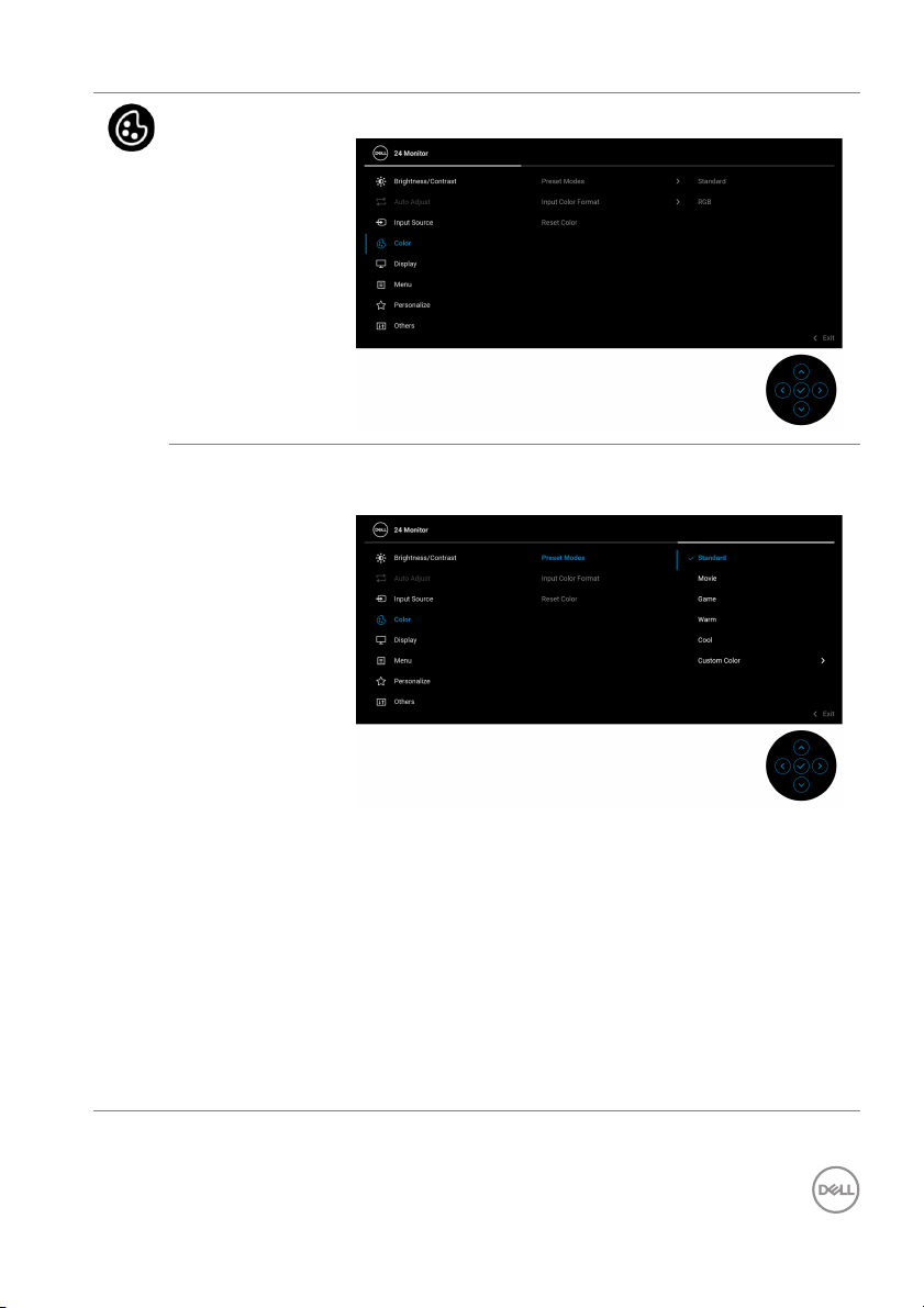
Color Use Color to adjust the color setting mode.
Preset Modes Allows you to choose from the list of preset color
modes. Press the joystick to confirm the selection.
• Standard: This is the defaul t setting. Using a low
blue light panel, this monitor is certified by TUV to
reduce blue light output and create more relaxing
and less stimulating images.
vie: Loads color settings ideal for movies.
• Mo
• Game: L
applications.
• Wa
temperatures. The screen appears warmer with a
red/yellow tint.
oads color settings ideal for most gaming
rm: Presents colors at lower color
Operating the monitor │ 47
Page 48
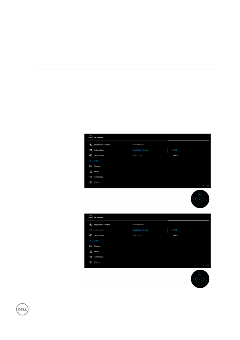
Preset Modes • Cool: Presents colors at higher color temperatures.
The screen appears cooler with a blue tint.
om Color: Allows you to manually adjust the
color settings. Use the joystick to adjust the three
colors (R, G, B) values and create your own preset
color mode.
elect this option if your monitor is
connected to a computer or a media player that
supports RGB output.
bCr/YPbPr*: Select this option if your media
player supports YCbCr (digital)/YPbPr (analog)
output.
Input Color
rmat
Fo
• Cust
Allows you to set the video input mode to:
• RGB: S
• YC
Press the joystick to confirm the selection.
*When VGA input is selected.
48 │ Operating the monitor
Page 49
Hue This feature can shift the color of the video image to
green or purple. This is used to adjust the desired flesh
tone color. Move the joystick to adjust the hue level
from '0' to '100'.
NOTE: Th
Movie or Game preset mode.
Saturation This feature can adjust the color saturation of the
video image
level from '0' to '100'.
NOTE: Th
Movie or Game preset mode.
Reset Color Resets your monitor’s color settings to the factory
se
ttings.
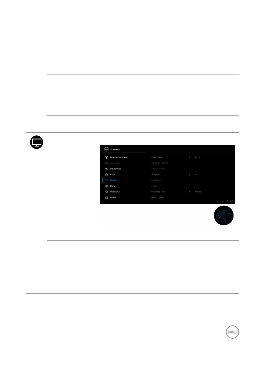
Display Use Display to adjust the images.
e feature is available only when you select
. Move the joystick to adjust the saturation
e feature is available only when you select
Aspect Ratio Adjusts the image ratio to 16:10, 4:3, or 5:4.
Horizontal
Po
sition
Vertical
Po
sition
Move the joystick to adjust the image left or right
(min. 0 / max. 100).
NOTE: T
Move the joystick to adjust the image up or down
(min. 0 / max. 100).
NOTE: T
he feature is only available for VGA input.
he feature is only available for VGA input.
Operating the monitor │ 49
Page 50
Sharpness This feature can make the image look sharper or
softer.
Move the joystick to adjust the sharpness level from
'0' to '100'.
Pixel Clock The Phase and Pixel Clock adjustments allow you to
adjust your monitor to your preference.
Move the joystick to adjust for best image quality.
NOTE: The feature is only available for VGA input.
Phase If satisfactory results are not obtained using the
Phase adjustment, use the Pixel Clock (coarse)
adjustment and then use Phase (fine) again.
NOTE: The feature is only available for VGA input.
Response Time Al lows you to set the Response Time to Normal or
Fast.
Reset Display Resets all display settings to the factory preset values.
50 │ Operating the monitor
Page 51
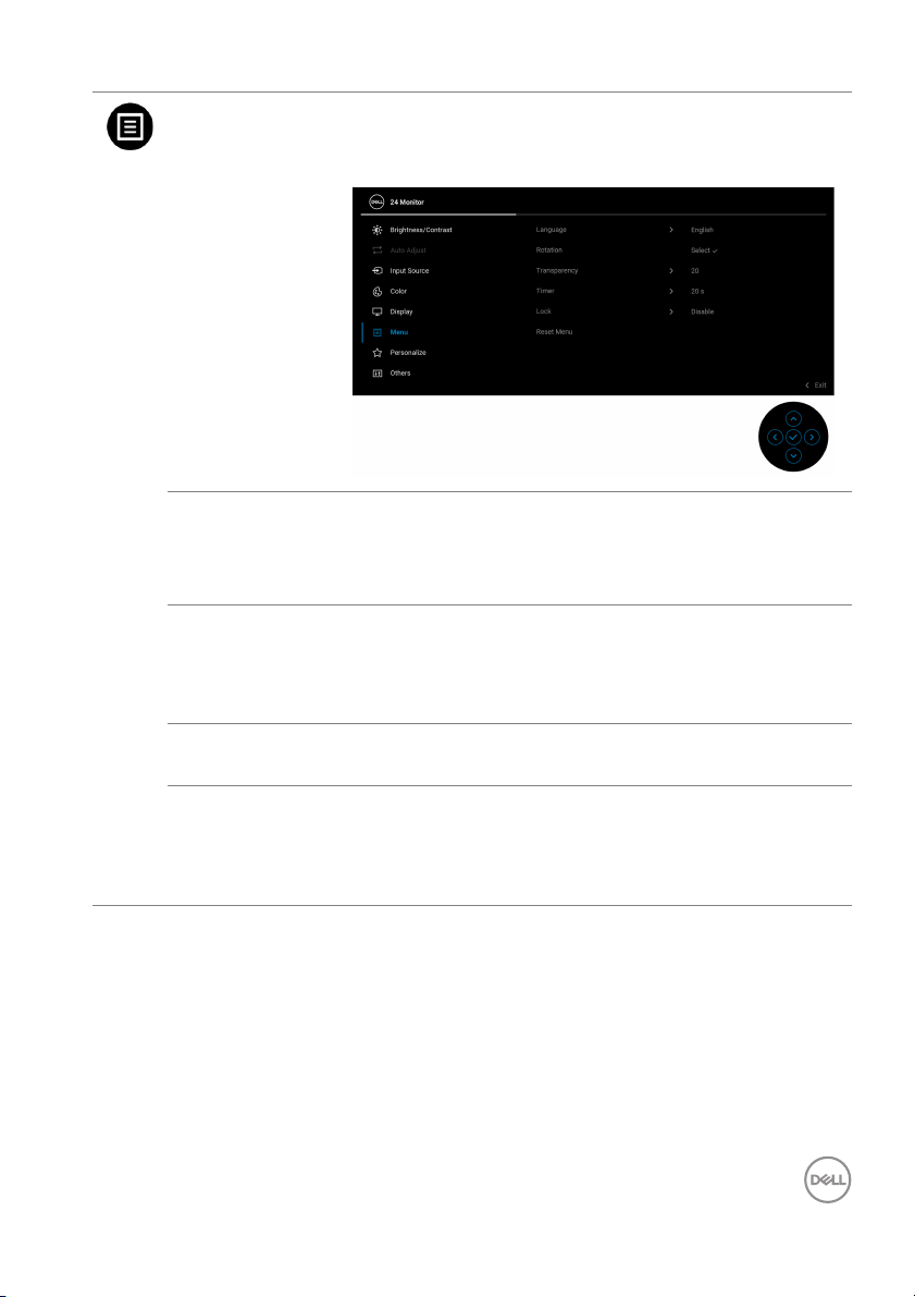
Menu Adjusts the settings of the OSD, such as, the
languages of the OSD, the amount of time the menu
remains on screen, and so on.
Language Sets the OSD display to one of the eight languages
(English, Spanish, French, German, Brazilian
Portuguese, Russian, Simplified Chinese, or
Japanese).
Rotation Press the joystick to rotate the OSD and the screen by
/90/180/270 degrees.
0
You can adjust the menu according to your display
tation.
ro
Transparency Select this feature to change the menu transparency
b
y moving the joystick (min. 0 / max. 100).
Tim er Sets the length of time the OSD will remain active
a
fter your last operation with the joystick.
Move the joystick to adjust the slider in 1 second
ncrement, from 5 to 60 seconds.
i
Operating the monitor │ 51
Page 52
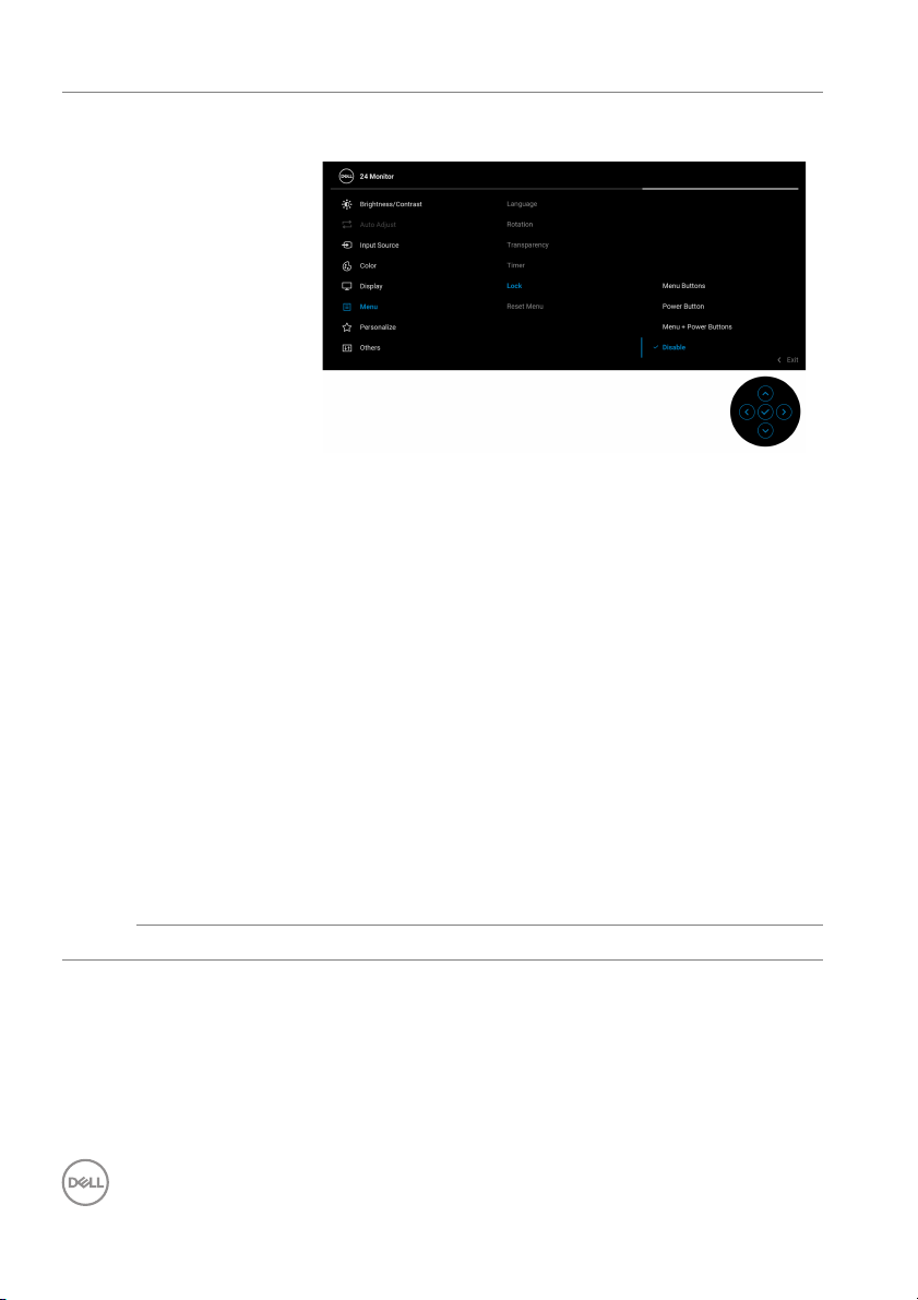
Lock With the control buttons on the monitor locked, you
can prevent people from accessing the controls.
• Menu Buttons: All joystick functions are locked
and not accessible by the user.
wer Button: Onl y the Power button is locked
• Po
and not accessible by the user.
• Menu
The default setting is Disab
Alternative Lock Method: You can move and hold the
jo
ystick up/down/left/right for 4 seconds to set the
lock options via the pop-up menu, and then press the
joystick to confirm the configuration.
NOTE: T
down/left/right for 4 seconds, and then press the
joystick to confirm to unlock and close the pop-up
menu.
Reset Menu Resets all OSD settings to the factory preset values.
+ Power Buttons: Both the joystick &
Power button are locked and not accessible by the
user.
le.
o unlock, move and hold the joystick up/
52 │ Operating the monitor
Page 53
Personal ize
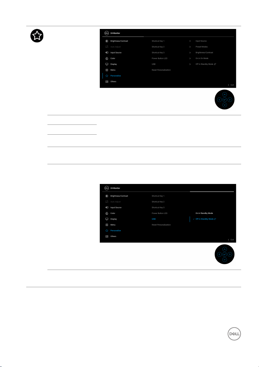
Shortcut Key 1 Al lows you to choose a feature from Preset Modes,
Shortcut Key 2
Shortcut Key 3
Power Button
LED
USB Allows you to enable or disable USB function during
Brightness/Contrast, Auto Adjust, Input Source,
Aspect Ratio, Rotation, or Display Info and set it as
a shortcut key.
Allows you to set the power LED indicator on or off to
ve energy.
sa
monit
or standby mode.
Reset
Personalization
Resets all settings under the Personal ize menu to
the factory preset values.
Operating the monitor │ 53
Page 54
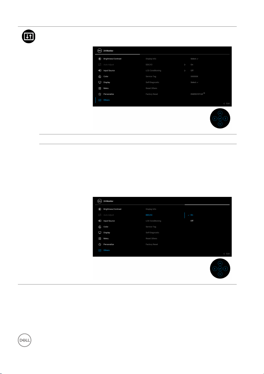
Others Allows you to adjust the OSD settings, such as DDC/
CI, LCD Conditioning, and so on.
Display Info Displays the monitor's current settings.
DDC/CI DDC/CI
allows you to adjust the monitor settings using
software on your computer. You can disable this
feature by selecting Off.
Enable this feature for best user experience and
op
(Display Data Channel/Command Interface)
timum performance of your monitor.
54 │ Operating the monitor
Page 55
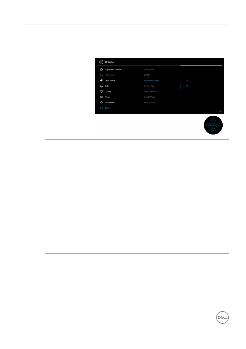
LCD
Conditioning
Service Tag Displays the service tag string of your monitor. This
Sel f-
Diagnostic
Reset Others Resets all settings under the Other
Helps reduce minor cases of image retention.
Depending on the degree of image retention, the
program may take some time to run. You can enable
this feature by selecting On.
string is required when you look for phone support,
check your warranty status, update drivers on Dell's
website, etc.
Initiates the following sel f-diagnostic process:
1. When initiated, a gray screen appears.
Carefully inspect the screen for abnormalities.
2.
3. Move the joystick. The color of the screen
changes to red.
4. Inspect the display for any abnormalities.
5. Repeat steps 3 and 4 to inspect the display in
green, blue, black, white and text screens.
The test is complete when the text screen appears.
ess the joystick to end the testing process.
Pr
s menu to the
factory preset values.
Operating the monitor │ 55
Page 56
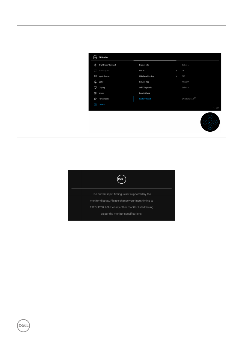
Factory Reset Restores all preset values to the factory default
s
ettings. These are also the settings for ENERGY
®
tests.
AR
ST
OSD warning message
When the monitor does not support a particular resolution mode, you will see the
following message:
This means that the monitor cannot synchronize with the signal that it is receiving
from the computer. See Monitor specifications for the Horizontal and Vertical
frequency ranges addressable by this monitor. The recommended mode is 19
20 x
1200.
56 │ Operating the monitor
Page 57
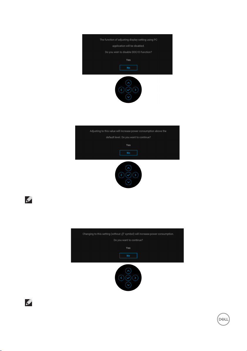
You will see the following message before the DDC/CI function is disabled:
When you adjust the Brightness level above the default level for the first time, the
following message appears:
NOTE: If you select Yes, the message will not appear the next time you
change the Brightness setting.
When you change the default USB setting for the first time
appears:
NOTE: If you select Yes, the message will not appear the next time you
change the USB setting. When you perform a factory reset, the
message will appear again.
Operating the monitor │ 57
, the following message
Page 58
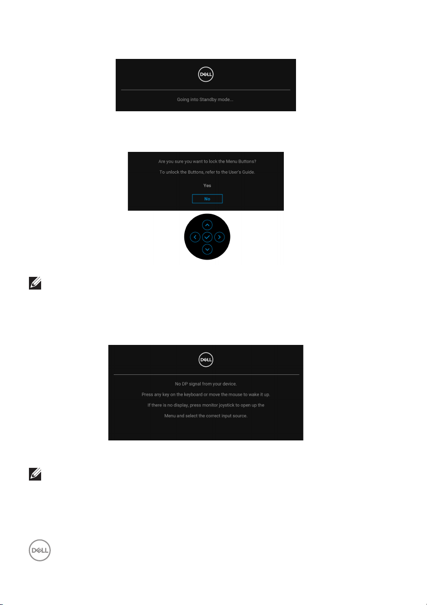
When the monitor goes into Standby mode, the following message appears:
Activate the computer and wake up the monitor to gain access to the OSD.
You will see the following message before the Lo
NOTE: The message may be slightly different according to the selected
settings.
The OSD functions only in the normal operation mode. If you press the joystick
during th
selected input:
e Standby mode, the following message will appear depending on the
ck function is activated:
Activate the computer and the monitor to gain access to the OSD.
NOTE: The message may be slightly different according to the
connected input signal.
58 │ Operating the monitor
Page 59
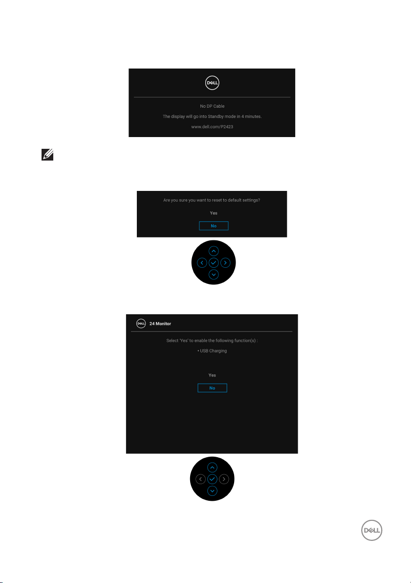
If VGA, DVI-D, DisplayPort, or HDMI input is selected and the corresponding cable is
not connected, the following message will appear:
NOTE: The message may be slightly different according to the selected
input signal.
When F
If you select Yes to reset to default settings, the following message appears:
actory Reset is selected, the following message appears:
See Tro ub l es ho ot in g for more information.
Operating the monitor │ 59
Page 60

Setting the maximum resolution
NOTE: The steps may vary slightly depending on the version of
Windows you have.
To set the maximum resolution for the monitor:
In Windows 8.1:
1. For Windows 8.1, select the Desktop tile to switch to classic desktop.
2. Right-click on the desktop and click Screen resolution.
3. If you have more than one monitor connected, ensure that you select P2423.
4. Click the Screen Resolution dropdown list and select 1920 x 1200.
5. Click OK.
In Windows 10 and Windows 11:
1. Right-click on the desktop and click Display settings.
2. If you have more than one monitor connected, ensure to select P2423.
3. Click the Resolution dropdown list and select 1920 x 1200.
4. Click Keep changes.
If you do not see 1920 x 1200 as an option, you must update your graphics driver to
the latest version. Depending on your computer, complete one of the following
procedures:
If you have a Dell desktop or laptop:
•Go to https://www.dell.com/support, enter your service tag, and download
the latest driver for your graphics card.
If you are using a non-Dell computer (laptop or desktop):
• Go to the support site for your computer and download the latest graphic
drivers.
• Go to your graphics card website and download the latest graphic drivers.
60 │ Operating the monitor
Page 61
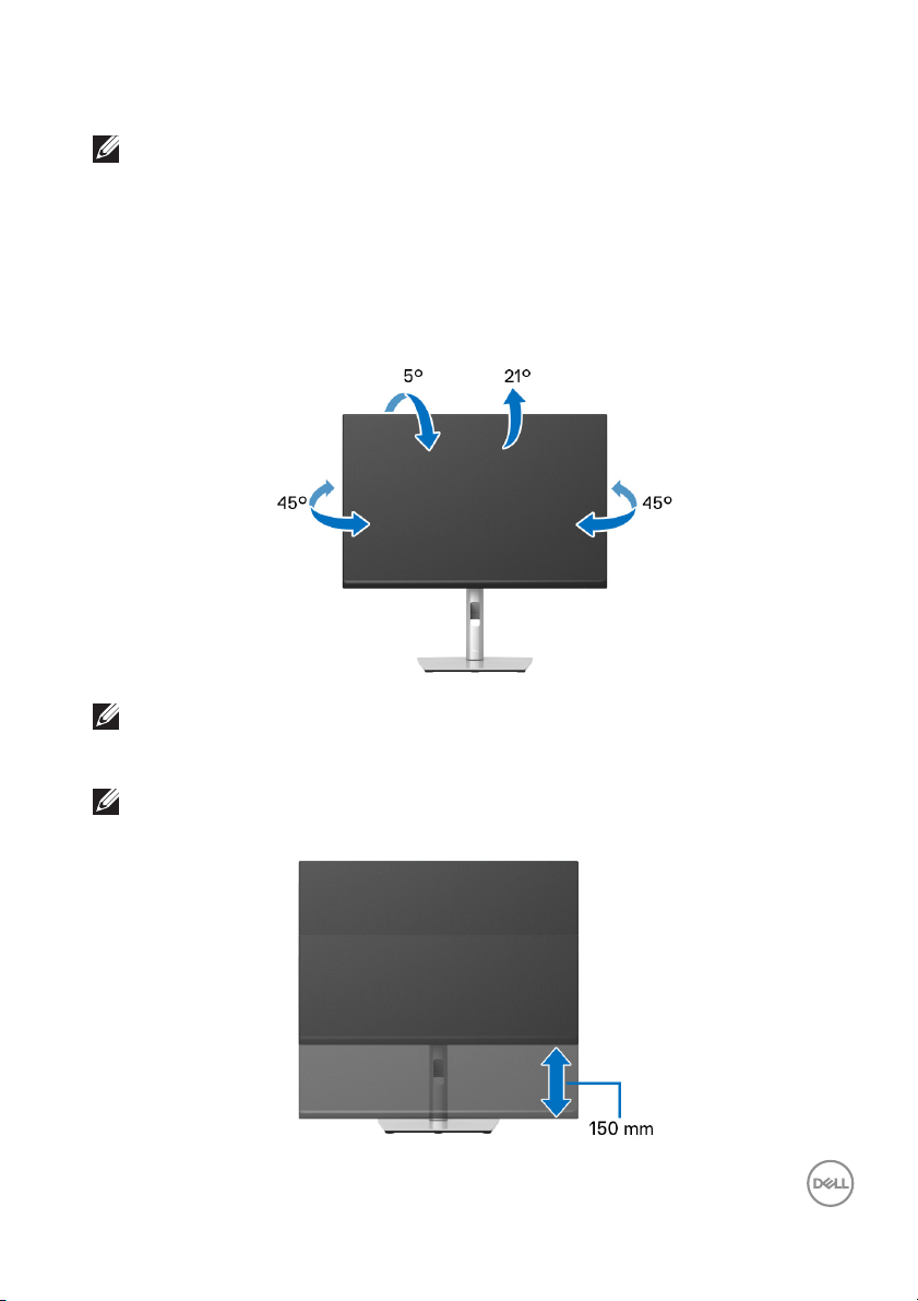
Using the tilt, swivel, and vertical extension
NOTE: The following instructions are applicable only for attaching the
stand that was shipped with your monitor. If you are attaching a stand
that you purchased from any other source, follow the setup
instructions available with the stand.
Ti l t, s w ive l
With the stand attached to the monitor, you
most comfortable viewing angle.
NOTE: The stand is not installed at the factory when shipped.
can tilt and swivel the monitor for the
Vertical extension
NOTE: The stand extends vertically up to 150 mm. The figure below
illustrates how to extend the stand vertically.
Operating the monitor │ 61
Page 62
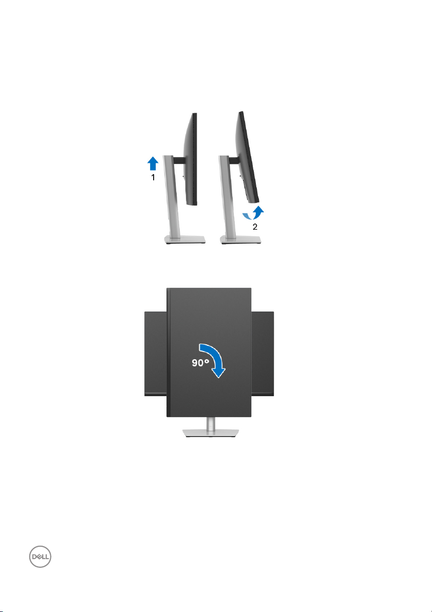
Rotating the monitor
Before you rotate the monitor, your monitor should be fully vertically extended
(Vertical extension) and fully tilted up to avoid hitting the bottom
monitor.
Rotate clockwise
edge of the
62 │ Operating the monitor
Page 63
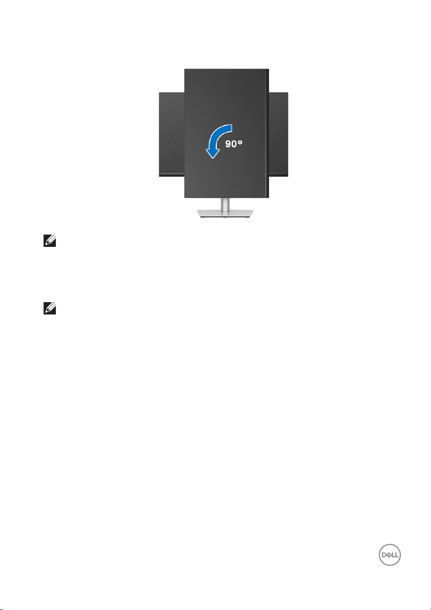
Rotate counterclockwise
NOTE: To use the Display Rotation function (Landscape versus Portrait
view) with your Dell computer, you require an updated graphics driver
that is not included with this monitor. To download the graphics driver,
go to www.dell.com/support and see the Download section for Video
Drivers for latest driver updates.
NOTE: When in the Portrait View Mode, you may experience
performance degradation in graphic-intensive applications (3D Gaming
and etc.).
Operating the monitor │ 63
Page 64

Adjusting the rotation display settings of your system
After you have rotated your monitor, you need to complete the procedure below to
adjust the Rotation Display Settings of your system.
NOTE: If you are using the monitor with a non-Dell computer, you need
to go the graphics driver website or your computer manufacturer
website for information on rotating the 'contents' on your display.
To adjust the Rotation Display Settings:
1. Right-click on the desktop and click Properties.
2. Select the Settings tab and click Advanced.
3. If you have an ATI graphics card, select the Rotation tab and set the
preferred rotation.
4. If you have an NVIDIA graphics card, click the NVIDIA tab, in the left-hand
column select NVRotate, and then select the preferred rotation.
5. If you have an Intel® graphics card, select the Intel graphics tab, click
Graphic Properties, select the Rotation tab, and then set the preferred
rotation.
NOTE: If you do not see the rotation option or it is not working
correctly, go to
for your graphics card.
www.del l.com/support and download the latest driver
64 │ Operating the monitor
Page 65
Troubleshooting
WARNING: Before you begin any of the procedures in this section,
fol low the Safety instructions.
Sel f-test
Your monitor provides a self-test feature that allows you to check whether your
monitor is functioning properly. If your monitor and computer are properly
connected but the monitor screen remains dark, run the monitor self-test by
performing the following steps:
urn off both your computer and the monitor.
1. T
2. Unp
lug the video cable from the computer.
3. T
urn on the monitor.
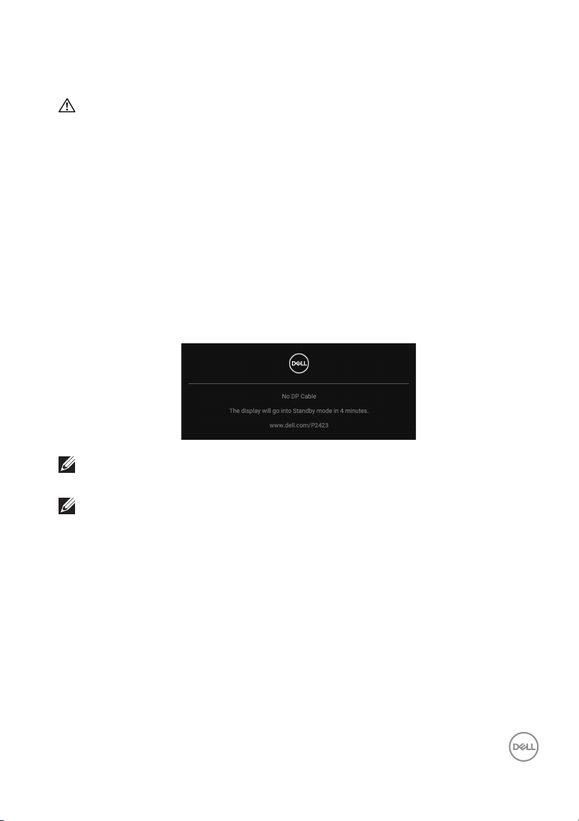
If the monitor cannot sense a video signal
message will appear:
NOTE: The message may be slightly different according to the
connected input signal.
and is working correctly, the following
NOTE: While in self-test mode, the power LED remains white.
4. T
his box also appears during normal system operation, if the video cable
becomes disconnected or damaged.
urn Off your monitor and reconnect the video cable; then turn On both your
5. T
computer and the monitor.
If your monitor screen remains blank after y
your video controller and computer, because your monitor is functioning properly.
ou use the previous procedure, check
Tro ub l es hoot in g │ 65
Page 66
Common problems
The following table contains general information about common monitor problems
you might encounter and the possible solutions:
Common
symptoms
No video/
power LED off
No video/
power LED on
Poor focus Picture is fuzzy,
What you
experience
No picture • Ensure that the video cable connecting
No picture or no
brightness
blurry, or
ghosting
Possible solutions
the monitor and the computer is properly
connected and secure.
• Verify that the power outlet is functioning
properly using any other electrical
equipment.
• Ensure that the power button is pressed
fully.
• Ensure that the correct input source is
selected in the
• Increase brightness and contrast controls
via OSD.
• Perform monitor self-test feature check
(see
Sel f-test).
• Check for bent or broken pins in the video
cable connector.
• Run the built-in diagnostics (see Self-
Diagnostic).
• Ensure that the correct input source is
selected in the
• Perform Auto Adjust via OSD.
• Adjust the Phase and Pixel Clock
controls via OSD.
• Eliminate video extension cables.
• Reset the monitor to factory settings.
• Change the video resolution to the correct
aspect ratio.
Input Source menu.
Input Source menu.
66 │ Tro ub l es hoot in g
Page 67

Shaky/jittery
video
Missing pixels LCD screen has
Stuck-on pixel s LCD screen has
Brightness
problems
Geometric
distortion
Wavy picture or
fine movement
spots
bright spots
Picture too dim
or too bright
Screen not
centered
correctly
• Perform Auto Adjust via OSD.
• Adjust the Phase and Pixel Clock
controls via OSD.
• Reset the monitor to factory settings.
• Check environmental factors.
• Relocate the monitor and test in another
room.
•Cycle power On-Off.
• Pixel that is permanently Off is a natural
defect that can occur in LCD technology.
• For more information on Del l Monitor
Quality and Pixel Policy, see Dell Support
site at:
•Cycle power On-Off.
• Pixel that is permanently off is a natural
defect that can occur in LCD technology.
• For more information on Del l Monitor
Quality and Pixel Policy, see Dell Support
site at:
• Reset the monitor to factory settings.
• Adjust brightness and contrast controls
via OSD.
• Reset the monitor to factory settings.
• Perform Auto Adjust via OSD.
• Adjust horizontal and vertical controls via
OSD.
• When using DVI-D/HDMI/DisplayPort
input, the positioning adjustments are not
avail able.
www.del l.com/pixelguidelines.
www.del l.com/pixelguidelines.
Tro ub l es hoot in g │ 67
Page 68
Horizontal/
vertical lines
Synchronization
problems
Safety related
issues
Intermittent
problems
Screen has one
or more lines
Screen is
scrambled or
appears torn
Visible signs of
smoke or sparks
Monitor
malfunctions on
and off
• Reset the monitor to factory settings.
• Perform Auto Adjust via OSD.
• Adjust the Phase and Pixel Clock
controls via OSD.
• Perform monitor self-test feature check
(see
Sel f-test) and determine if these
lines are also in self-test mode.
• Check for bent or broken pins in the video
cable connector.
• Run the built-in diagnostics (see Self-
Diagnostic).
• When using DVI-D/HDMI/DisplayPort
input, the Pixel Clock and Phase
adjustments are not available.
• Reset the monitor to factory settings.
• Perform Auto Adjust via OSD.
• Adjust the Phase and Pixel Clock
controls via OSD.
• Perform monitor self-test feature check
(see
Sel f-test) to determine if the
scrambled screen appears in self-test
mode.
• Check for bent or broken pins in the video
cable connector.
• Restart the computer in the safe mode.
• Do not perform any troubleshooting steps.
•Contact Dell immediately.
• Ensure that the video cable connecting
the monitor to the computer is connected
properly and is secure.
• Reset the monitor to factory settings.
• Perform monitor self-test feature check
(see
Sel f-test) to determine if the
intermittent problem occurs in self-test
mode.
68 │ Tro u bl es hoot in g
Page 69
Missing color Picture missing
color
Wrong color Picture color
not good
Image retention
from a static
image left on
the monitor for
a long period of
time
Video ghosting
or overshooting
Faint shadow
from the static
image displayed
appears on the
screen
Video ghosting,
shadows or
color smear
while scrol ling
• Perform monitor self-test feature check
(see
Sel f-test).
• Ensure that the video cable connecting
the monitor to the computer is connected
properly and is secure.
• Check for bent or broken pins in the video
cable connector.
• Change the settings of the Preset
Modes in the Color menu OSD
depending on the application.
• Adjust the R/G/B values under Custom
Color in the Color menu OSD.
• Change the Input Color Format to RGB
or YCbCr/YPbPr in the Color settings
OSD.
• Run the built-in diagnostics (see Sel f-
Diagnostic).
• Set the screen to turn off after a few
minutes of screen idle time. These can be
adjusted in Windows Power Options or
Mac Energy Saver setting.
• Al ternatively, use a dynamicall y changing
screensaver.
• Change the Response Time in the
Display menu OSD to Normal or Fast,
depending on your application and usage.
NOTE: Auto Adjust is only available when you use the analog (VGA)
connector.
Tro ub l e sh o ot in g │ 69
Page 70
Product specific problems
Common
symptoms
Screen image is too
sma
ll
Cannot adjust the
or with the
monit
joystick
No input signal
en user controls
wh
are pressed
The picture does
no
t fill the entire
screen
What you
experience
Image is centered on
screen, but does not
fill entire viewing
area
OSD does not
appear on the screen
No picture, the LED
light is white
The picture cannot
fill the height or
width of the screen
Possible solutions
• Check the Asp
the Display menu OSD.
• Reset the monitor to factory settings.
• Turn Off the monitor, unplug the
power cord, plug it back, and then
turn On the monitor.
• Check whether the OSD menu is
ocked. If yes, move and hold the
l
joystick up/down/left/right for 4
seconds to unlock (for more
information, see Lock).
• Check the signal source. Ensure the
computer is not in the power saving
mode by moving the mouse or
pressing any key on the keyboard.
• Check whether the signal cable is
lugged in properly. Re-plug the
p
signal cable if necessary.
• Reset the computer or video player.
• Due to different video formats
(aspect ratio) of DVDs, the monitor
may display in full screen.
• Run the built-in diagnostics (see
Sel f-Diagnostic).
ect Ratio setting in
70 │ Tro ub l es hoot in g
Page 71
Universal Serial Bus (USB) specific problems
Common
symptoms
USB interface is
no
t working
SuperSpeed USB
5 Gbps (USB 3.2
n1) interface is
Ge
slow
Wireless USB
periph
erals stop
working when a
USB 3.2 device is
plugged in
What you
experience
USB peripherals
are not working
SuperSpeed USB
5 Gbps (USB 3.2
1) peripherals
Gen
working slowly or
not working at all
Wireless USB
ripherals
pe
responding sl owl y
or only working as
the distance
between itself and
its receiver
decreases
Possible solutions
• Check that your monitor is turned On.
• Reconnect the upstream cable to your
com
puter.
• Reconnect the USB peripherals
downstream connector).
(
• Turn off the monitor and turn it on
ain.
ag
• Reboot the computer.
• Some USB devices like external
able HDD require higher electric
port
current; connect the device directly to
the computer system.
• Check that your computer is
SuperSp
Gen
• Some computers have USB 3.2, USB
2.
correct USB port is used.
• Reconnect the upstream cable to your
com
• Reconnect the USB peripherals
downstream connector).
(
• Reboot the computer.
• Increase the distance between the
USB 3
USB receiver.
• Position your wireless USB receiver as
lose as possible to the wireless USB
c
peripherals.
• Use a USB-extender cable to position
th
as possible from the USB 3.2 port.
eed USB 5 Gbps (USB 3.2
1)-compatible.
0, and USB 1.1 ports. Ensure that the
puter.
.2 peripherals and the wireless
e wireless USB receiver as far away
Tro u bl es hoot in g │ 71
Page 72

Appendix
FCC notices (U.S. only) and other regulatory information
For FCC notices and other regulatory information, see the regulatory compliance
website located at
Contact Del l
For customers in the United States, call 800-WWW-DELL (800-999-3355).
NOTE: If you do not have an active Internet connection, you can find
contact information on your purchase invoice, packing slip, bill, or Dell
product catalog.
Dell provides several online and telephone-based support and service
options. Availability varies by country and product, and some services may
not be available in your area.
• Online technical assistance — www.del l.com/support/monitors
•Contacting Dell — www.dell.com/contactdell
EU product database for energy label and product information sheet
P2423: https://eprel.ec.europa.eu/qr/1043228
www.del l.com/regulatory_compliance.
72 │ Appendix
 Loading...