

Dell OptiPlex N, OptiPlex N Series Service Manual

'HOO2SWL3OH[16\VWHPV
6(59,&(0$18$/
®

____________________
Information in this manual is subject to change without notice.
1997-1998 Dell Computer Corpora tion. All rights reserved.
Reproduction in any manner whatsoever without the written permission of Del l Computer Corporation is strictly forbidden.
Trademarks used in this text: Dell, the DELL logo, and OptiPlex are registered trademarks of Dell Computer Corporation; Intel and Pentium are registered trademarks
and MMX and EtherExpress are trademarks of Intel Corporation; MS-DOS is a registered tradem ark of Microsoft Corpora t ion; IBM is a registered trademark of
International Busin ess Ma chines Corporation; 3C om is a re gistered trademark of 3Com Corporation.
Other trademarks and tr ade names may be used in this document to refer to either the ent it ie s cl ai m ing the marks and names or their products. Dell Computer
Corporation disclai m s any pr oprietary interest in trademarks and trade name s other than its own.
February 1998 P/N 57646 Rev. A01

Contents
Chapter 1
System Overview. . . . . . . . . . . . . . . . . . . . . . . . . . . . . . . 1-1
System Features . . . . . . . . . . . . . . . . . . . . . . . . . . . . . . . . . . . . . . . . . . . . . . . 1-2
Expansion-Card Slot. . . . . . . . . . . . . . . . . . . . . . . . . . . . . . . . . . . . . . . . . 1-4
Hard-Disk Drive . . . . . . . . . . . . . . . . . . . . . . . . . . . . . . . . . . . . . . . . . . . . 1-4
Enhanced Dual-Interface EIDE Subsystem . . . . . . . . . . . . . . . . . . . . . . . 1-4
Built-In Video Controller . . . . . . . . . . . . . . . . . . . . . . . . . . . . . . . . . . . . . 1-4
Optional Built-In NIC. . . . . . . . . . . . . . . . . . . . . . . . . . . . . . . . . . . . . . . . 1-5
Stand for Vertical Orientation. . . . . . . . . . . . . . . . . . . . . . . . . . . . . . . . . . 1-5
Computer Service . . . . . . . . . . . . . . . . . . . . . . . . . . . . . . . . . . . . . . . . . . . . . . 1-6
Computer Power Supply. . . . . . . . . . . . . . . . . . . . . . . . . . . . . . . . . . . . . . 1-6
Pin Assignments for the DC Power Connectors. . . . . . . . . . . . . . . . . 1-7
DC Power Distribution . . . . . . . . . . . . . . . . . . . . . . . . . . . . . . . . . . . . 1-8
System Board . . . . . . . . . . . . . . . . . . . . . . . . . . . . . . . . . . . . . . . . . . . . . 1-10
Main Memory . . . . . . . . . . . . . . . . . . . . . . . . . . . . . . . . . . . . . . . . . . 1-11
System Board Jumpers . . . . . . . . . . . . . . . . . . . . . . . . . . . . . . . . . . . 1-11
Interrupt Assignments. . . . . . . . . . . . . . . . . . . . . . . . . . . . . . . . . . . . . . . . . . 1-13
DMA Channel Assignments. . . . . . . . . . . . . . . . . . . . . . . . . . . . . . . . . . . . . 1-14
Technical Specifications. . . . . . . . . . . . . . . . . . . . . . . . . . . . . . . . . . . . . . . . 1-15
Chapter 2
Basic Troubleshooting . . . . . . . . . . . . . . . . . . . . . . . . . . 2-1
Initial User Contact. . . . . . . . . . . . . . . . . . . . . . . . . . . . . . . . . . . . . . . . . . . . . 2-1
External Visual Inspection . . . . . . . . . . . . . . . . . . . . . . . . . . . . . . . . . . . . . . . 2-2
Observing the Boot Routine . . . . . . . . . . . . . . . . . . . . . . . . . . . . . . . . . . . . . . 2-3
Server-Based Diagnostics. . . . . . . . . . . . . . . . . . . . . . . . . . . . . . . . . . . . . . . . 2-4
Hard-Disk–Based Diagnostics . . . . . . . . . . . . . . . . . . . . . . . . . . . . . . . . . . . . 2-5
Internal Visual Inspection. . . . . . . . . . . . . . . . . . . . . . . . . . . . . . . . . . . . . . . . 2-7
v

Diskette-Based Diagnostics . . . . . . . . . . . . . . . . . . . . . . . . . . . . . . . . . . . . . . 2-8
Connecting the External Diskette Drive. . . . . . . . . . . . . . . . . . . . . . . . . . 2-8
Running the Diskette-Based Diagnostics. . . . . . . . . . . . . . . . . . . . . . . . . 2-9
Getting Help. . . . . . . . . . . . . . . . . . . . . . . . . . . . . . . . . . . . . . . . . . . . . . . . . 2-10
Chapter 3
Beep Codes and Error Messages . . . . . . . . . . . . . . . . . . 3-1
POST Beep Codes . . . . . . . . . . . . . . . . . . . . . . . . . . . . . . . . . . . . . . . . . . . . . 3-1
System Error Messages . . . . . . . . . . . . . . . . . . . . . . . . . . . . . . . . . . . . . . . . . 3-4
Chapter 4
Removing and Replacing Parts . . . . . . . . . . . . . . . . . . . 4-1
Recommended Tools . . . . . . . . . . . . . . . . . . . . . . . . . . . . . . . . . . . . . . . . . . . 4-1
Precautionary Measures . . . . . . . . . . . . . . . . . . . . . . . . . . . . . . . . . . . . . . . . . 4-2
Stand for Vertical Orientation . . . . . . . . . . . . . . . . . . . . . . . . . . . . . . . . . . . . 4-3
Computer Cover. . . . . . . . . . . . . . . . . . . . . . . . . . . . . . . . . . . . . . . . . . . . . . . 4-4
Control Panel . . . . . . . . . . . . . . . . . . . . . . . . . . . . . . . . . . . . . . . . . . . . . . . . . 4-6
Hard-Disk Drive. . . . . . . . . . . . . . . . . . . . . . . . . . . . . . . . . . . . . . . . . . . . . . . 4-7
System Power Supply. . . . . . . . . . . . . . . . . . . . . . . . . . . . . . . . . . . . . . . . . . . 4-8
System Board Components . . . . . . . . . . . . . . . . . . . . . . . . . . . . . . . . . . . . . . 4-9
Expansion-Card Cage. . . . . . . . . . . . . . . . . . . . . . . . . . . . . . . . . . . . . . . 4-10
Expansion Card . . . . . . . . . . . . . . . . . . . . . . . . . . . . . . . . . . . . . . . . . . . 4-11
Riser Board. . . . . . . . . . . . . . . . . . . . . . . . . . . . . . . . . . . . . . . . . . . . . . . 4-12
DIMMs. . . . . . . . . . . . . . . . . . . . . . . . . . . . . . . . . . . . . . . . . . . . . . . . . . 4-13
Microprocessor/Heat Sink Assembly. . . . . . . . . . . . . . . . . . . . . . . . . . . 4-14
System Battery . . . . . . . . . . . . . . . . . . . . . . . . . . . . . . . . . . . . . . . . . . . . 4-16
System Board . . . . . . . . . . . . . . . . . . . . . . . . . . . . . . . . . . . . . . . . . . . . . . . . 4-17
Appendix A
System Setup Program . . . . . . . . . . . . . . . . . . . . . . . . . .A-1
System Setup Screens. . . . . . . . . . . . . . . . . . . . . . . . . . . . . . . . . . . . . . . . . . .A-2
Index
Figures
Figure 1-1. Computer Orientation . . . . . . . . . . . . . . . . . . . . . . . . . . . . . . . 1-2
Figure 1-2. Front-Panel Features . . . . . . . . . . . . . . . . . . . . . . . . . . . . . . . . 1-3
Figure 1-3. Internal View. . . . . . . . . . . . . . . . . . . . . . . . . . . . . . . . . . . . . . 1-3
vi

Figure 1-4. Riser Board . . . . . . . . . . . . . . . . . . . . . . . . . . . . . . . . . . . . . . . 1-4
Figure 1-5. NIC Connector on I/O Panel . . . . . . . . . . . . . . . . . . . . . . . . . . 1-5
Figure 1-6. DC Power Connector P1 . . . . . . . . . . . . . . . . . . . . . . . . . . . . . 1-7
Figure 1-7. DC Power Connector P2 . . . . . . . . . . . . . . . . . . . . . . . . . . . . . 1-7
Figure 1-8. DC Power Connector P3 . . . . . . . . . . . . . . . . . . . . . . . . . . . . . 1-8
Figure 1-9. DC Power Cables. . . . . . . . . . . . . . . . . . . . . . . . . . . . . . . . . . . 1-8
Figure 1-10. DC Power Distribution. . . . . . . . . . . . . . . . . . . . . . . . . . . . . . . 1-9
Figure 1-11. System Board Components . . . . . . . . . . . . . . . . . . . . . . . . . . 1-10
Figure 1-12. System Board Jumpers. . . . . . . . . . . . . . . . . . . . . . . . . . . . . . 1-11
Figure 2-1. External Diskette Drive . . . . . . . . . . . . . . . . . . . . . . . . . . . . . . 2-8
Figure 4-1. Optional Stand Removal . . . . . . . . . . . . . . . . . . . . . . . . . . . . . 4-3
Figure 4-2. Computer Cover Removal . . . . . . . . . . . . . . . . . . . . . . . . . . . . 4-4
Figure 4-3. Service Access Lock . . . . . . . . . . . . . . . . . . . . . . . . . . . . . . . . 4-4
Figure 4-4. Control Panel Removal . . . . . . . . . . . . . . . . . . . . . . . . . . . . . . 4-6
Figure 4-5. Hard-Disk Drive Removal . . . . . . . . . . . . . . . . . . . . . . . . . . . . 4-7
Figure 4-6. System Power-Supply Removal. . . . . . . . . . . . . . . . . . . . . . . . 4-8
Figure 4-7. System Board Components . . . . . . . . . . . . . . . . . . . . . . . . . . . 4-9
Figure 4-8. Expansion-Card Cage Removal. . . . . . . . . . . . . . . . . . . . . . . 4-10
Figure 4-9. Expansion-Card Removal . . . . . . . . . . . . . . . . . . . . . . . . . . . 4-11
Figure 4-10. Riser Board Removal. . . . . . . . . . . . . . . . . . . . . . . . . . . . . . . 4-12
Figure 4-11. DIMM Removal. . . . . . . . . . . . . . . . . . . . . . . . . . . . . . . . . . . 4-13
Figure 4-12. DIMM Installation . . . . . . . . . . . . . . . . . . . . . . . . . . . . . . . . . 4-13
Figure 4-13. Microprocessor Removal. . . . . . . . . . . . . . . . . . . . . . . . . . . . 4-14
Figure 4-14. Microprocessor Securing-Clip Removal . . . . . . . . . . . . . . . . 4-15
Figure 4-15. System Battery Removal . . . . . . . . . . . . . . . . . . . . . . . . . . . . 4-16
Figure 4-16. System Board Removal . . . . . . . . . . . . . . . . . . . . . . . . . . . . . 4-17
Figure A-1. System Setup Screens . . . . . . . . . . . . . . . . . . . . . . . . . . . . . . .A-2
Figure A-2. Sample Device List Screen . . . . . . . . . . . . . . . . . . . . . . . . . . .A-6
Tables
Table 1-1. DC Voltage Ranges . . . . . . . . . . . . . . . . . . . . . . . . . . . . . . . . . 1-6
Table 1-2. System-Board Jumper Descriptions. . . . . . . . . . . . . . . . . . . . 1-12
Table 1-3. Interrupt Assignments . . . . . . . . . . . . . . . . . . . . . . . . . . . . . . 1-13
Table 1-4. DREQ Line Assignments. . . . . . . . . . . . . . . . . . . . . . . . . . . . 1-14
Table 1-5. Technical Specifications . . . . . . . . . . . . . . . . . . . . . . . . . . . . 1-15
Table 3-1. POST Beep Codes . . . . . . . . . . . . . . . . . . . . . . . . . . . . . . . . . . 3-2
Table 3-2. System Error Messages . . . . . . . . . . . . . . . . . . . . . . . . . . . . . . 3-5
Table A-1. System Setup Categories . . . . . . . . . . . . . . . . . . . . . . . . . . . . .A-3
vii

ead This First
R
A prerequisite for using this manual to service Dell computer systems is a
basic knowledge of IBM®-compatible PCs and prior training in IBMcompatible PC troubleshooting techniques. In addition to information
provided in this manual a nd the User’s Guide that came with the system, Dell
provides the Diagnostics and T roubleshooting Guide for troubleshooting procedures and instructions on using the Dell diagnostics to test the computer
system.
arnings, Cautions, and Notes
W
Throughout this manual, there may be blocks of text printed in bold type or in
italic type. These blocks are warnings, cautions, and notes, and they are used as
follows:
WARNING: A WARNING indicates the potential for bodily harm and provides instructions for how to avoid the problem.
CAUTION: A CAUTION indicates either potential damage to hardware or
loss of data and provides instructions for how to avoid the problem.
NOTE: A NOTE pr o v ides helpful information about using the computer system.
viii

Chapter 1
System Overview
he Dell
T
designed for centrally managed network operation. These computers have a
small-footprint, locked chassis with no externally accessible drives.
The OptiPlex N computers use the Intel® Pentium® microprocessor with
MMX™ technology. The microprocessor is installed in a type 7 ZIF socket,
allowing the computer to be upgraded when faster microprocessors become
available.
The Pentium microprocessor contains a built-in clock multiplier circuit, which
increases the internal operating frequency to a multiple of the system clock frequency. The microprocessors for Dell OptiPlex N computers operate at a
frequency of 166 MHz, 200 MHz, or 233 MHz, derived from a system clock
frequency of 66 MHz.
These Dell computers incorporate the high-performance PCI expansion bus.
This bus is built into the system board, which also integrates the microprocessor, memory controller, hard-disk drive controller, video controller, and
other elements of the basic computer.
®
OptiPlex® N computers are high-speed, upgradable computers
System Overview 1-1

S
left
side
front
right
side
back
ystem Features
In addition to the standard features found in a traditional personal computer , the
Dell OptiPlex N computers include the following new and/or advanced
features:
One PCI expansion-card slot on a riser board
•
One EIDE hard-disk drive
•
Ultra DMA/33 EIDE interface for hard-disk drive transfer rates of up to
•
33 MB/sec
Support for connecting an external diskette drive for troubleshooting
•
purposes
Integrated cache memory controller that supports 512 KB of external
•
pipelined-burst cache memory
Main system memory consisting of 16 to 256 MB of high-speed EDO
•
DIMMs
Built-in SVGA controller attached to the PCI bus with 2 MB of video
•
memory
Optional integrated 10/100-Mbps Ethernet NIC
•
Optional NIC expansion card providing Wakeup On LAN capability
•
Integrated Universal Serial Bus (USB) controller with two USB-compliant
•
connectors
SMART-compliant hard-disk drive and SMART support in the system
•
BIOS, which provides notification at system start-up if the hard-disk drive
has become unreliable
Server-based, hard-disk–based, and diskette-based diagnostics capabilities
•
For a complete list of system features, see “Technical Specifications” found
later in this chapter.
When following the text in this manual, assume that the location or direction
relative to the computer is as shown in Figure 1-1.
Figure 1-1. Computer Orientation
1-2 Dell OptiPlex N Systems Service Manual
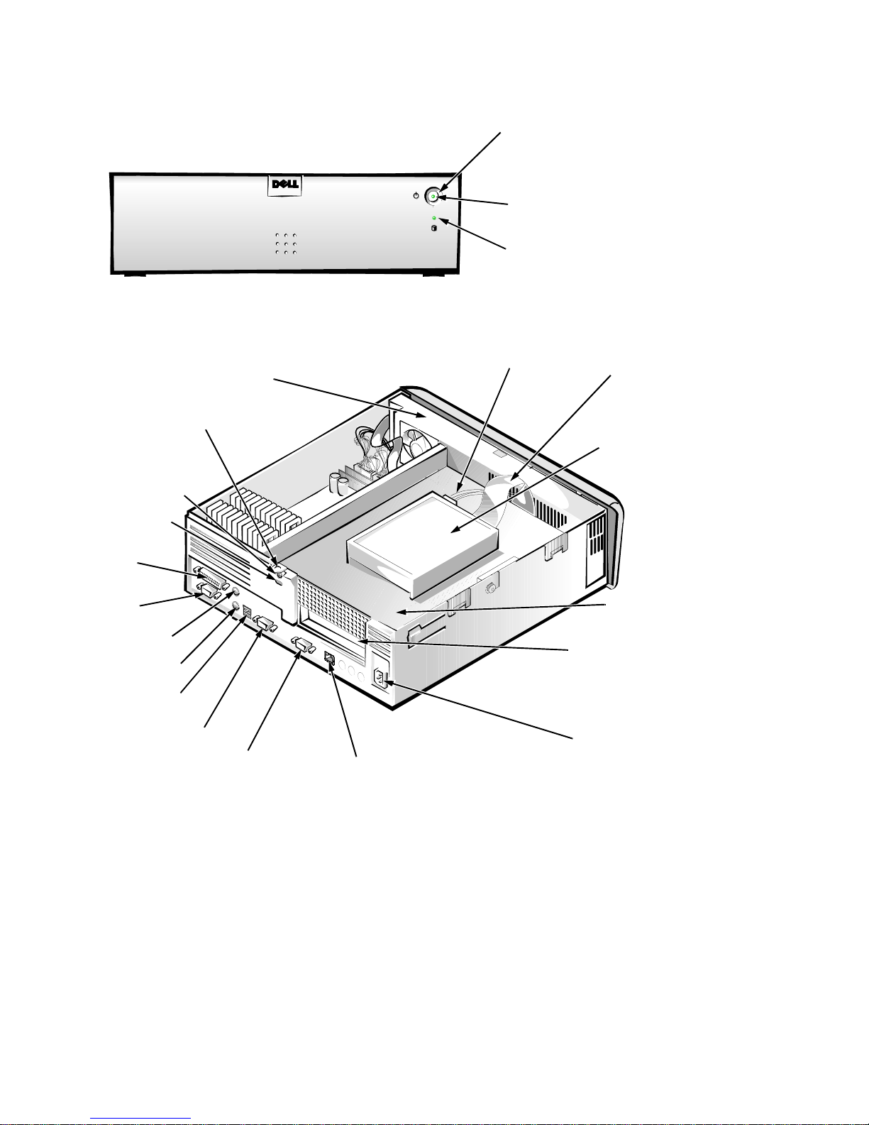
Figures 1-2 and 1-3 show the system’ s front-panel features and internal features,
respectively .
power button
power indicator
hard-disk drive
access indicator
Figure 1-2. Front-Panel Features
padlock ring
security access lock
security cable slot
parallel port
connector
serial port 1
connector
mouse connector
keyboard connector
USB connectors (2)
serial port 2 connector
video connector
power supply
NIC connector (optional)
DC power cable
expansion-card slot
AC power
receptacle
EIDE cable
hard-disk drive
expansion-card
cage
Figure 1-3. Internal View
System Overview 1-3
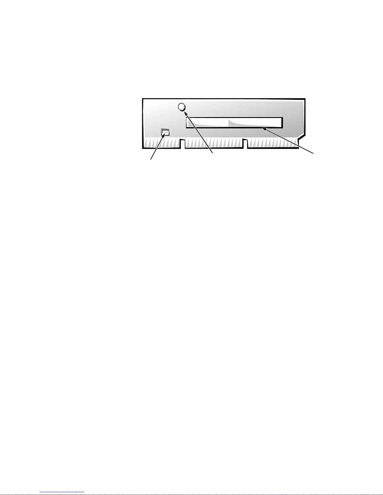
Expansion-Card Slot
PCI1
connector
power LED
Wakeup On LAN
power connector
The computer has one PCI expansion-card connector on the riser board (see
Figure 1-4). The computer automatically assigns any required memory space,
IRQ lines, and DMA channels to an installed PCI expansion card during system
start-up. The Wakeup On LAN power connector on the riser board supports an
optional NIC expansion card with Wakeup On LAN capability. The power LED
illuminates when DC power is applied to the riser board.
Figure 1-4. Riser Board
Hard-Disk Drive
One 1-inch-high EIDE hard-disk drive can be mounted to the top of the
expansion-card cage.
Enhanced Dual-Interface EIDE Subsystem
The EIDE subsystem provides two mode-4, DMA bus-mastered EIDE interfaces, each of which can support up to two EIDE devices. The EIDE controller
attaches to the high-speed PCI local bus. Any attached EIDE device should be
configured for the Cable Select jumper position. The computer’s boot drive
should be connected to the primary EIDE interface (IDE1).
NOTE: Although the OptiPlex N system board supports up to four EIDE
devices, no devices other than the internal hard-disk drive should be connected.
Built-In Video Controller
The video subsystem consists of a high-speed, high-resolution S3 Trio 64V2
86C785 video controller built into the system board. The video controller connects to the PCI bus, which operates at a frequency of 33 MHz.
The built-in video controller includes 2 MB of video memory built into the system board.
1-4 Dell OptiPlex N Systems Service Manual
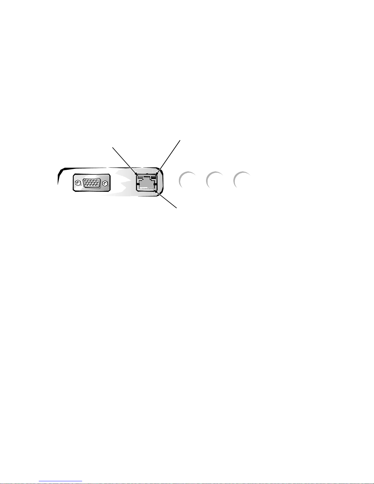
Optional Built-In NIC
The Dell OptiPlex N computers offer an optional integrated 10/100-Mbps
3Com® PCI 3C905 Ethernet NIC subsystem. The NIC provides all the functions of a separate 3Com 3C905 network expansion card and supports the
100BASE-TX Ethernet standards. Category 5 wiring and connections must be
used.
The integrated NIC does not support the Wakeup On LAN feature. Wakeup
On LAN capability is provided by an optional NIC expansion card such as the
Intel EtherExpress™ PRO/100M.
The NIC subsystem connects to the Ethernet network through an RJ45 connector on the back panel of the computer.
link integrity
indicator
activity
indicator
NIC connector
Figure 1-5. NIC Connector on I/O Panel
On computers with the optional built-in NIC, the NIC (RJ45) connector and
NIC interface circuitry are mounted on the system board. The connector
includes the following indicators (see Figure 1-5):
A yellow activity indicator flashes when the computer is transmitting or
•
receiving network data. (A high volume of network traffic may make this
indicator appear to be in a steady “on” state.)
A green link integrity indicator lights up when there is a good connection
•
between the network and the NIC. When the green indicator is off, the computer is not detecting a physical connection to the network.
“Network Considerations” in the online Network Administrator’s Guide pro-
vides instructions for connecting the computer to, and configuring it for use on,
an Ethernet network.
Stand for Vertical Orientation
The computer can be used in a vertical orientation by attaching an available
stand to the left side of the computer.
System Overview 1-5

C
omputer Service
The following subsections provide service-related information about the
computer.
Computer Power Supply
The Dell OptiPlex N computers have an 80-W computer power supply. The
power supply can operate from an AC power source of 115 VAC at 60 Hz or
230 VAC at 50 Hz. The computer power supply provides the DC operating voltages and currents listed in Table 1-1.
NOTE: The power supply produces DC voltages only under its loaded condition. Therefore, when you measure these voltages, the DC power connectors
must be connected to their corresponding pow er input connectors on the system
board and hard-disk drive.
.
Table 1-1. DC Voltage Ranges
Voltage Range Maximum Output Current
+3.3 VDC +3.135 to +3.465 VDC
+5 VDC +4.75 to +5.25 VDC
+12 VDC +11.40 to +12.60 VDC
6.0 A
12.0 A
1.0 A
1
1
2
1
–12 VDC –10.80 to –13.20 VDC 0.5 A
+5 VFP
1
The combined load on the +5-VDC and +3.3-VDC outputs should not exceed 65 W.
2
Withstands surges of up to 3.0 A to support disk start-up operations.
3
VFP (volts flea power) — sometimes called “standby power.”
3
+4.75 to +5.25 VDC 1.2 A
1-6 Dell OptiPlex N Systems Service Manual

Pin Assignments for the DC Power Connectors
The power-supply output voltages can be measured at the back (wire side) of
the connectors without disconnecting them. Figures 1-6 through 1-8 show the
wire side of the connectors.
open
common (black)
common (black)
common (black)
1
PSON#
(grey)
11
12 13 14 15 16 17 18 19 20
+5 VDC (red)
+5 VDC (red)
+5 VDC (red)
2
TFSC
(brown)
+5 VDC (red)
P1
234 5678 910
1
+5 VDC (red)
common (black)
+5 VDC (red)
common (black)
3
PWRGOOD
1
Pin 11 — PSON# should measure between +4 and +5 VDC except when the power button
(orange)
common (black)
common (black)
–12 VDC (blue)
+12 VDC (yellow)
+5 VFP (purple)
on the front panel is pressed, taking PSON# to its active-low state.
2
Pin 19 — Thermal fan-speed control (TFSC) is a power-supply input signal used to control
the power-supply fan speed.
3
Pin 5 — PWRGOOD should measure between +4 and +5 VDC when the power supply is
on to indicate that all power-supply output voltages are within the ranges specified in
Table 1-1.
Figure 1-6. DC Power Connector P1
1234
5
Figure 1-7. DC Power Connector P2
P2
6
+3.3 VDC (blue/white)
+3.3 VDC (blue/white)
+3.3 VDC (blue/white)
common (black)
common (black)
common (black)
System Overview 1-7

Figure 1-8. DC Power Connector P3
1 2 3 4
+5 VDC (red)
common (black)
common (black)
+12 VDC (yellow)
P3
P3P2P1
DC Power Distribution
Figures 1-9 and 1-10 provide the following information about DC power
distribution:
Power-supply connector identification
•
Power cable connection for the hard-disk drive
•
Power distribution to sockets and connectors on the system board
•
Figure 1-9. DC Power Cables
1-8 Dell OptiPlex N Systems Service Manual
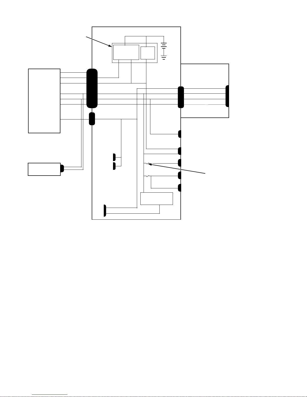
keyboard
controller
+3 VDC
system board
computer
power supply
internal
hard-disk drive
PWRGOOD
PSON#
+5 VFP
+5 VDC
+12 VDC
–12 VDC
+3.3 VDC
P3
P1 POWER_1
PSON#
+5 VFP
+5 VDC
+12 VDC
–12 VDC
POWER_2
P2
main memory
sockets
DIMM_A
DIMM_B
MICROPROCESSOR
core VCC +2.1 to +3.5 VDC
power
management
logic
+3.3 VDC
RTC/
NVRAM
+3.3 VDC
+5 VDC
+12 VDC
–12 VDC
RISER
+12 VDC
+5 VFP
+5 VDC
+5 VDC
+5 VDC
+5 VDC
processor core
regulator
battery
FAN
PANEL
USB
KYBD
MOUSE
riser board
+3.3 VDC
+5 VDC
+12 VDC
–12 VDC
fuses (2)
PCI1
Figure 1-10. DC Power Distribution
System Overview 1-9
System Board
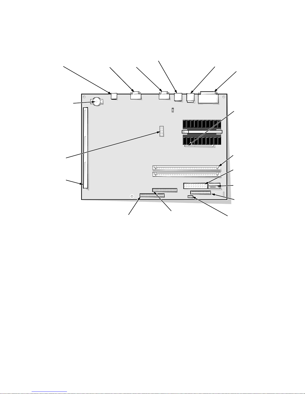
The subsections that follow provide service-related information about the system board and its components (see Figure 1-11).
NIC connector
(ENET)
battery socket
(BATTERY)
system board
jumpers
riser board
connector
(RISER)
video connector
(MONITOR)
serial port 2
connector
(SERIAL2)
USB connectors (2)
(USB)
keyboard/mouse
connectors (stacked)
(KYBD/MOUSE)
parallel/serial port 1
connectors (stacked)
(PARALLEL/SERIAL)
microprocessor socket
(MICROPROCESSOR)
(pin-1 corner)
DIMM sockets (2)
(DIMM_A)
main power input
connector (POWER_1)
3.3-V power input
connector (POWER_2)
front of computer
primary EIDE
interface connector
(IDE1) (pin-1 corner)
secondary EIDE
interface connector
(IDE2) (pin-1 corner)
Figure 1-11. System Board Components
diskette/tape drive
interface connector
(DSKT) (pin-1 corner)
control panel
connector (PANEL)
1-10 Dell OptiPlex N Systems Service Manual

Main Memory
The two DIMM sockets on the system board can accommodate combinations of
16-, 32-, 64-, and 128-MB DIMMs up to a total memory capacity of 256 MB.
Although 64-bit nonparity EDO DIMMs are recommended, 72-bit parity
DIMMs can also be installed. The standard main memory is 16 MB of highspeed (60-ns) nonparity memory. For optimum performance, install DIMMs in
consecutive sockets starting with socket DIMM_A.
System Board Jumpers
Figure 1-12 shows the location of the jumper blocks on the system board. See
Table 1-2 for the jumper descriptions and settings.
jumpered
unjumpered
Figure 1-12. System Board Jumpers
System Overview 1-11

Table 1-2. System-Board Jumper Descriptions
Jumper Description Settings
133 Reserved Do not install jumper.
166
*
Microprocessor
speed
Install jumper if the microprocessor’s
internal speed is 166 MHz; otherwise the
jumper should not be installed.
200
*
Microprocessor
speed
Install jumper if the microprocessor’s
internal speed is 200 MHz; otherwise the
jumper should not be installed.
233
*
Microprocessor
speed
Install jumper if the microprocessor’s
internal speed is 233 MHz; otherwise the
jumper should not be installed.
PSWD Password
enable or
disable
Install to enable the password features.
Remove the PSWD jumper and boot the
computer to remove an existing password.
BIOS Reserved Do not install jumper.
* One set of the speed jumper pins must have a jumper plug installed; otherwise, the computer will
operate at an undetermined speed.
1-12 Dell OptiPlex N Systems Service Manual

I
nterrupt Assignments
Table 1-3 shows the assignment or availability of IRQ lines.
Table 1-3. Interrupt Assignments
IRQ Line Used By/Available
IRQ0 Generated by system timer.
IRQ1 Generated by keyboard controller to indicate that keyboard’s out-
put buffer is full.
IRQ2 Generated internally by interrupt controller to enable IRQ8
through IRQ15.
IRQ3 Generated by super I/O controller to indicate that the device con-
nected to serial port 2 (COM2 or COM4) requires service.
IRQ4 Generated by super I/O controller to indicate that the device con-
nected to serial port 1 (COM1 or COM3) requires service.
IRQ5 Available for use by an expansion card.
IRQ6 Generated by super I/O controller to indicate that diskette
requires service.
IRQ7 Generated by super I/O controller to indicate that device con-
nected to parallel port requires service.
IRQ8 Generated by keyboard controller for each tick of RTC.
IRQ9 Available for use by video controller to indicate that the video or
monitor requires service.
IRQ10 Available for use by an expansion card.
IRQ11 Available for use by an expansion card.
IRQ12 Generated by keyboard controller to indi cate that mouse’s output
buffer is full.
IRQ13 Generated by math coprocessor to indicate coprocessor error.
IRQ14 Generated by hard-disk drive connected to primary EIDE port to
indicate that drive requires service. If the EIDE controller is dis-
abled, this line is available for other use.
IRQ15
* Although the OptiPlex N system board supports up to four EI DE devices, no devices other than
the internal hard-disk drive should be connected.
Generated by device connected to secondary EIDE port to
*
indicate that device requires service. If the EIDE controller is not
in use, this line is available for other use.
System Overview 1-13

D
MA Channel Assignments
Table 1-4 shows the assignment or availability of DREQ lines.
Table 1-4. DREQ Line Assignments
DREQ Line Used By/Available
DREQ0 Available
DREQ1 Available
DREQ2 Generated by super I/O controller to initiate DMA cycle for
attached diskette drive
DREQ3 Available
DREQ4 Generated by bus controller chip to activate second DMA
controller
DREQ5 Available
DREQ6 Available
DREQ7 Available
NOTES: The video controller and optional built-in NIC controller are assigned available
DMA channels automatically during computer start-up.
If the parallel port is in ECP mode, it uses one of the available DREQ lines.
1-14 Dell OptiPlex N Systems Service Manual

T
echnical Specifications
Table 1-5 provides technical specifications for the OptiPlex N systems.
z
Table 1-5. Technical Specifications
Microprocessor
Microprocessor type . . . . . . . Intel Pentium microprocessor with MMX
technology
Microprocessor speed . . . . . . 166, 200, or 233 MHz
Internal system clock . . . . . . 66 MHz
Internal cache . . . . . . . . . . . . 32 KB (16-KB data cache; 16-KB instruc-
tion cache)
Math coprocessor . . . . . . . . . internal to the microprocessor
System Information
System chip set . . . . . . . . . . . Intel 430TX PCI chip set
Data bus width . . . . . . . . . . . 64 bits
Address bus width. . . . . . . . . 32 bits
DMA channels . . . . . . . . . . . seven
Interrupt levels . . . . . . . . . . . 15
Flash EPROM (BIOS) . . . . . 2 Mb (256 KB)
Expansion Bus
Bus type . . . . . . . . . . . . . . . . PCI (complies with PCI specification 2.1)
Bus speed . . . . . . . . . . . . . . . 33 MHz
PCI expansion-card connectors
one
NIC
NIC . . . . . . . . . . . . . . . . . . . . optional integrated 3Com PCI 3C905 net-
work controller, operating at 10 or
100 Mbps
System Overview 1-15

Table 1-5. Technical Specifications
Memory
(continued)
Architecture . . . . . . . . . . . . . 64-bit (nonparity) or 72-bit (parity) EDO,
noninterleaved
DIMM sockets . . . . . . . . . . . two (gold contacts)
DIMM capacities . . . . . . . . . 16-, 32-, 64-, and 128-MB EDO parity or
nonparity (recommended)
Standard RAM . . . . . . . . . . . 16 MB
Maximum RAM. . . . . . . . . . 256 MB
Cache memory . . . . . . . . . . . 512-KB pipelined-burst, direct-mapped,
write-back SRAM
BIOS address . . . . . . . . . . . . F0000h
Drives
Internal hard-disk drive . . . . one 3.5-inch, 1-inch high EIDE hard-disk
drive
Video
Video type. . . . . . . . . . . . . . . S3 Trio 64V2 86C785 built-in SVGA
controller attached to the PCI bus
Video memory . . . . . . . . . . . 2 MB
Maximum video
resolution. . . . . . . . . . . . . . . .
1280 x 1024 pixels with 256 colors,
noninterlaced; 1024 x 768 pixels with
65,536 colors, noninterlaced
Ports
Externally accessible:
Serial (DTE). . . . . . . . . . two 9-pin connectors (16550-compatible)
Parallel . . . . . . . . . . . . . . one 25-hole connector (bidirectional)
Video . . . . . . . . . . . . . . . one 15-hole connector
PS/2-style keyboard . . . . 6-pin mini-DIN connector
PS/2-compatible
mouse . . . . . . . . . . . . . . . 6-pin mini-DIN connector
NIC (optional) . . . . . . . . RJ45 connector
USB . . . . . . . . . . . . . . . . two USB-compliant connectors
1-16 Dell OptiPlex N Systems Service Manual
 Loading...