

Dell OptiPlex 3050 User Manual

Dell OptiPlex 3050 All-in-One
Owner's Manual
Regulatory Model: W18B
Regulatory Type: W18B001

Notes, cautions, and warnings
NOTE: A NOTE indicates important information that helps you make better use of your product.
CAUTION: A CAUTION indicates either potential damage to hardware or loss of data and tells you how to avoid the problem.
WARNING: A WARNING indicates a potential for property damage, personal injury, or death.
© 2016 Dell Inc. or its subsidiaries. All rights reserved. This product is protected by U.S. and international copyright and intellectual property laws. Dell and
the Dell logo are trademarks of Dell Inc. in the United States and/or other jurisdictions. All other marks and names mentioned herein may be trademarks of
their respective companies.
2017 - 06
Rev. A01

Contents
1 Working on your computer............................................................................................................................. 7
Safety instructions............................................................................................................................................................. 7
Before working inside your computer.............................................................................................................................. 7
Turning o your computer.................................................................................................................................................7
Turning o your computer — Windows 10...............................................................................................................8
Turning o your computer — Windows 7.................................................................................................................8
After working inside your computer.................................................................................................................................8
Important Information........................................................................................................................................................8
2 Removing and installing components.............................................................................................................9
Stand................................................................................................................................................................................... 9
Removing easel stand..................................................................................................................................................9
Installing easel stand...................................................................................................................................................10
Installing Height Adjustable Stand - HAS.................................................................................................................10
Removing Height Adjustable Stand.......................................................................................................................... 12
Optical drive...................................................................................................................................................................... 12
Removing optical drive...............................................................................................................................................12
Installing optical drive................................................................................................................................................. 13
Back cover.........................................................................................................................................................................13
Removing back cover.................................................................................................................................................13
Installing back cover...................................................................................................................................................14
Intrusion switch.................................................................................................................................................................14
Removing intrusion switch.........................................................................................................................................14
Installing intrusion switch...........................................................................................................................................15
System board shield......................................................................................................................................................... 15
Removing system board shield................................................................................................................................. 15
Installing system board shield.................................................................................................................................... 16
Hard drive.......................................................................................................................................................................... 16
Removing hard drive.................................................................................................................................................. 16
Installing hard drive ....................................................................................................................................................17
Cable holder.......................................................................................................................................................................17
Removing cable holder...............................................................................................................................................17
Installing cable holder ................................................................................................................................................ 18
Memory modules.............................................................................................................................................................. 18
Removing memory module........................................................................................................................................18
Installing memory module.......................................................................................................................................... 19
Coin cell battery................................................................................................................................................................19
Removing coin cell battery........................................................................................................................................ 19
Installing coin cell battery..........................................................................................................................................20
Solid State Drive — optional ......................................................................................................................................... 20
Removing Solid State Drive (SSD) card..................................................................................................................20
Installing Solid State Drive (SSD) card.....................................................................................................................21
WLAN card........................................................................................................................................................................ 21
Contents
3

Removing WLAN card................................................................................................................................................21
Installing WLAN card................................................................................................................................................. 22
Heat sink .......................................................................................................................................................................... 22
Removing heat sink .................................................................................................................................................. 22
Installing heat sink .....................................................................................................................................................23
System fan........................................................................................................................................................................23
Removing system fan (35 W optional)....................................................................................................................23
Installing system fan (35 W optional)...................................................................................................................... 24
Removing system fan (65 W).................................................................................................................................. 24
Installing system fan (65 W).....................................................................................................................................25
Power and On-Screen Display........................................................................................................................................25
Removing power and On-Screen Display (OSD) board ....................................................................................... 25
Installing power and On-Screen Display (OSD) board...........................................................................................26
Speaker............................................................................................................................................................................. 26
Removing speaker .................................................................................................................................................... 26
Installing speaker........................................................................................................................................................28
VGA/Serial port (optional)..............................................................................................................................................28
Removing VGA/serial port (optional)......................................................................................................................28
Installing VGA/serial port (optional)........................................................................................................................ 29
Processor..........................................................................................................................................................................29
Removing processor..................................................................................................................................................29
Installing processor.................................................................................................................................................... 30
System board................................................................................................................................................................... 30
Removing system board............................................................................................................................................30
Installing system board.............................................................................................................................................. 33
Chassis frame...................................................................................................................................................................33
Removing chassis frame........................................................................................................................................... 33
Installing chassis frame..............................................................................................................................................35
Display assembly.............................................................................................................................................................. 36
Removing display assembly...................................................................................................................................... 36
Installing display assembly.........................................................................................................................................37
Camera..............................................................................................................................................................................38
Removing camera...................................................................................................................................................... 38
Installing camera.........................................................................................................................................................39
M.2 Intel Optane Memory Module 16 GB..................................................................................................................... 39
Overview.....................................................................................................................................................................39
Intel®OptaneTM Memory Module Driver Requirements..................................................................................... 40
Installing M.2 Intel Optane Memory Module 16 GB...............................................................................................40
Product specications................................................................................................................................................41
Environmental Conditions.........................................................................................................................................42
Troubleshooting..........................................................................................................................................................43
3 Technology and components....................................................................................................................... 45
Chipsets............................................................................................................................................................................ 45
Identifying chipset in Device Manager on Windows 7...........................................................................................45
Identifying the chipset in Device Manager on Windows 10..................................................................................45
Intel HD Graphics drivers.......................................................................................................................................... 45
Contents
4

Downloading the chipset driver............................................................................................................................... 46
Downloading drivers.................................................................................................................................................. 46
Display options..................................................................................................................................................................46
Identifying the display adapter (Windows 7 and Windows 10).............................................................................46
Changing the screen resolution (Windows 7 and Windows 10)........................................................................... 47
Adjusting brightness in Windows 7.......................................................................................................................... 47
Adjusting brightness in Windows 10........................................................................................................................ 47
Connecting to external display devices (Windows 7, 8.1 and 10)..........................................................................47
Intel HD Graphics ............................................................................................................................................................ 47
Intel HD Graphics drivers...........................................................................................................................................47
Hard drive options............................................................................................................................................................48
Identifying the hard drive in Windows 7..................................................................................................................48
Identifying the hard drive in Windows 10................................................................................................................48
Entering BIOS setup..................................................................................................................................................48
USB features.................................................................................................................................................................... 48
USB 3.0/USB 3.1 Gen 1 (SuperSpeed USB)...........................................................................................................49
Speed.......................................................................................................................................................................... 49
Applications................................................................................................................................................................ 50
Compatibility...............................................................................................................................................................50
Memory features.............................................................................................................................................................. 51
Verifying system memory in Windows 10 and Windows 7 ....................................................................................51
Verifying system memory in setup............................................................................................................................51
DDR4............................................................................................................................................................................ 51
Testing memory using ePSA.....................................................................................................................................52
Realtek HD audio drivers.................................................................................................................................................53
4 System setup...............................................................................................................................................54
BIOS Overview.................................................................................................................................................................54
Boot menu.................................................................................................................................................................. 54
System setup options................................................................................................................................................54
5 Technical specications...............................................................................................................................63
Processor specications................................................................................................................................................. 63
Memory specications.................................................................................................................................................... 64
Video specications.........................................................................................................................................................64
Audio specications.........................................................................................................................................................64
Communication specications........................................................................................................................................64
Cards specications.........................................................................................................................................................65
Display specications.......................................................................................................................................................65
Drives specications........................................................................................................................................................65
Port and connector specications.................................................................................................................................65
Power specications....................................................................................................................................................... 66
Camera specications..................................................................................................................................................... 66
Stand specications........................................................................................................................................................ 66
Physical specications.....................................................................................................................................................66
Environmental specications.......................................................................................................................................... 67
Contents
5

6 Troubleshooting...........................................................................................................................................68
Enhanced Pre-Boot System Assessment — ePSA diagnostics................................................................................68
Running the ePSA diagnostics.......................................................................................................................................68
LCD built in self test (BIST)............................................................................................................................................68
Invoking BIST with user modes................................................................................................................................70
OSD toggle..................................................................................................................................................................70
ePSA............................................................................................................................................................................70
7 Contacting Dell............................................................................................................................................ 72
6 Contents

Working on your computer
Safety instructions
Use the following safety guidelines to protect your computer from potential damage and to ensure your personal safety. Unless otherwise
noted, each procedure included in this document assumes that the following conditions exist:
• You have read the safety information that shipped with your computer.
• A component can be replaced or, if purchased separately, installed by performing the removal procedure in reverse order.
WARNING: Disconnect all power sources before opening the computer cover or panels. After you nish working inside the
computer, replace all covers, panels, and screws before connecting to the power source.
WARNING: Before working inside your computer, read the safety information that shipped with your computer. For additional
safety best practices information, see the Regulatory Compliance Homepage at www.Dell.com/regulatory_compliance
CAUTION: Many repairs may only be done by a certied service technician. You should only perform troubleshooting and simple
repairs as authorized in your product documentation, or as directed by the online or telephone service and support team.
Damage due to servicing that is not authorized by Dell is not covered by your warranty. Read and follow the safety instructions
that came with the product.
CAUTION: To avoid electrostatic discharge, ground yourself by using a wrist grounding strap or by periodically touching an
unpainted metal surface at the same time as touching a connector on the back of the computer.
CAUTION: Handle components and cards with care. Do not touch the components or contacts on a card. Hold a card by its
edges or by its metal mounting bracket. Hold a component such as a processor by its edges, not by its pins.
CAUTION: When you disconnect a cable, pull on its connector or on its pull-tab, not on the cable itself. Some cables have
connectors with locking tabs; if you are disconnecting this type of cable, press in on the locking tabs before you disconnect the
cable. As you pull connectors apart, keep them evenly aligned to avoid bending any connector pins. Also, before you connect a
cable, ensure that both connectors are correctly oriented and aligned.
NOTE: The color of your computer and certain components may appear dierently than shown in this document.
1
Before working inside your computer
To avoid damaging your computer, perform the following steps before you begin working inside the computer.
1 Ensure that you follow the Safety Instruction.
2 Ensure that your work surface is at and clean to prevent the computer cover from being scratched.
3 Ensure you follow the Turning o your computer .
4 Disconnect all network cables from the computer.
CAUTION
network device.
5 Disconnect your computer and all attached devices from their electrical outlets.
6 Press and hold the power button while the computer is unplugged to ground the system board.
NOTE
unpainted metal surface at the same time as touching a connector on the back of the computer.
: To disconnect a network cable, rst unplug the cable from your computer and then unplug the cable from the
: To avoid electrostatic discharge, ground yourself by using a wrist grounding strap or by periodically touching an
Turning o your computer
Working on your computer 7

Turning o your computer — Windows 10
CAUTION: To avoid losing data, save and close all open les and exit all open programs before you turn o your computer .
Click or tap .
1
2 Click or tap and then click or tap Shut down.
NOTE: Ensure that the computer and all attached devices are turned o. If your computer and attached devices did not
automatically turn o when you shut down your operating system, press and hold the power button for about 6 seconds to
turn them o.
Turning o your computer — Windows 7
CAUTION: To avoid losing data, save and close all open les and exit all open programs before you turn o your computer.
1 Click Start.
2 Click Shut Down.
NOTE
: Ensure that the computer and all attached devices are turned o. If your computer and attached devices did not
automatically turn o when you shut down your operating system, press and hold the power button for about 6 seconds to
turn them o.
After working inside your computer
After you complete any replacement procedure, ensure that you connect any external devices, cards, and cables before turning on your
computer.
1 Connect any telephone or network cables to your computer.
CAUTION
computer.
2 Connect your computer and all attached devices to their electrical outlets.
3 Turn on your computer.
4 If required, verify that the computer works correctly by running ePSA diagnostics.
: To connect a network cable, rst plug the cable into the network device and then plug it into the
Important Information
: Avoid using the touchscreen in dusty, hot, or humid environments.
NOTE
NOTE: Sudden change in temperature may cause condensation on the inner surface of the glass screen, which will disappear
after a short time and does not aect normal usage.
8 Working on your computer
Removing and installing components
This section provides detailed information on how to remove or install the components from your computer.
Stand
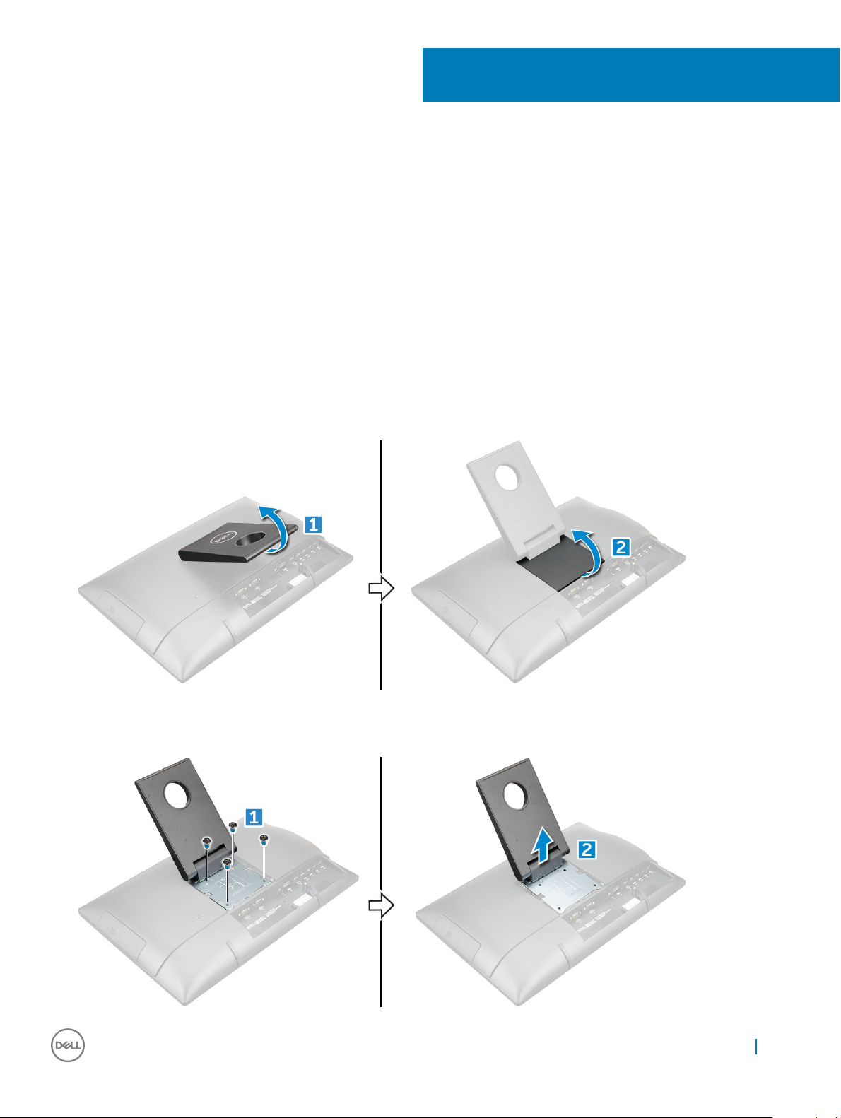
Removing easel stand
1 Follow the procedure in Before working inside your computer.
2 Place the computer on a at surface with the display facing downward.
3 To lift the stand:
a Lift the stand to access the stand cover.[1].
b Hold the stand cover and lift it away from the computer [2].
2
4 To remove stand:
a Remove the screws that secure the stand [1].
b Push the stand to release the metal plate from the notches of the back cover and lift it from the computer [2].
Removing and installing components 9
Installing easel stand
1 Position the stand to allow the metal plate tab to align with the notches on the back cover.
2 Replace the M4x7 screws to secure the stand to the computer.
3 Place the cover on the metal plate until snaps in.
4 Follow the procedure in After working inside your computer.
Installing Height Adjustable Stand - HAS
NOTE: A separate VESA bracket and 2 screws are provided to install the Height adjustable stand.
NOTE: Before installing HAS stand, follow the procedure to install VESA bracket.
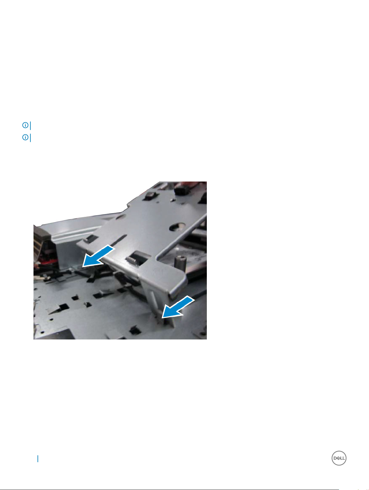
1 Remove the:
a optical drive
b back cover
2 Insert the VESA bracket into its slot on the computer.
3 Install the screws to secure the VESA bracket on the computer.
10
Removing and installing components
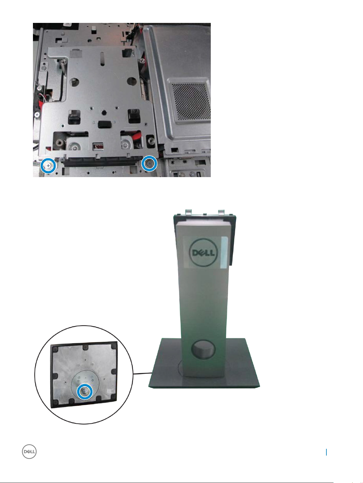
4 Close the back cover.
5 Install optical drive.
6 Position the stand to allow the metal plate tab to align with the notches on the back cover.
7 Place the cover on the metal plate until snaps in.
Removing and installing components
11
8 Follow the procedure in After working inside your computer.
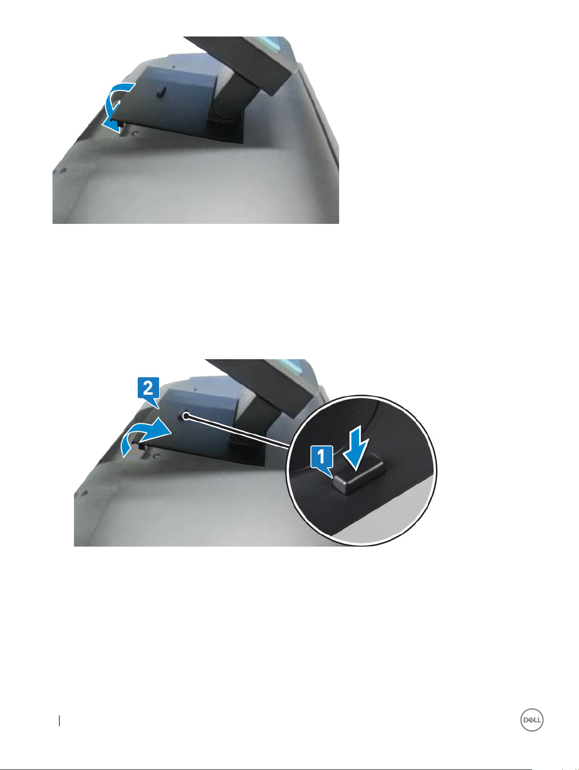
Removing Height Adjustable Stand
1 Follow the procedure in Before working inside your computer.
2 Place the computer on clean, at surface with the display facing downward.
3 To remove the stand:.
a Press the tab on the cover to release the stand [1].
b Lift the stand upward [2].
Optical drive
Removing optical drive
1 Follow the procedure in Before working inside your computer.
2 Remove the stand.
3 To remove the optical drive:
a Using a plastic scribe push the metal tab that is beneath the cover to release the optical drive [1].
b Remove the optical drive from the computer [2].
12
Removing and installing components
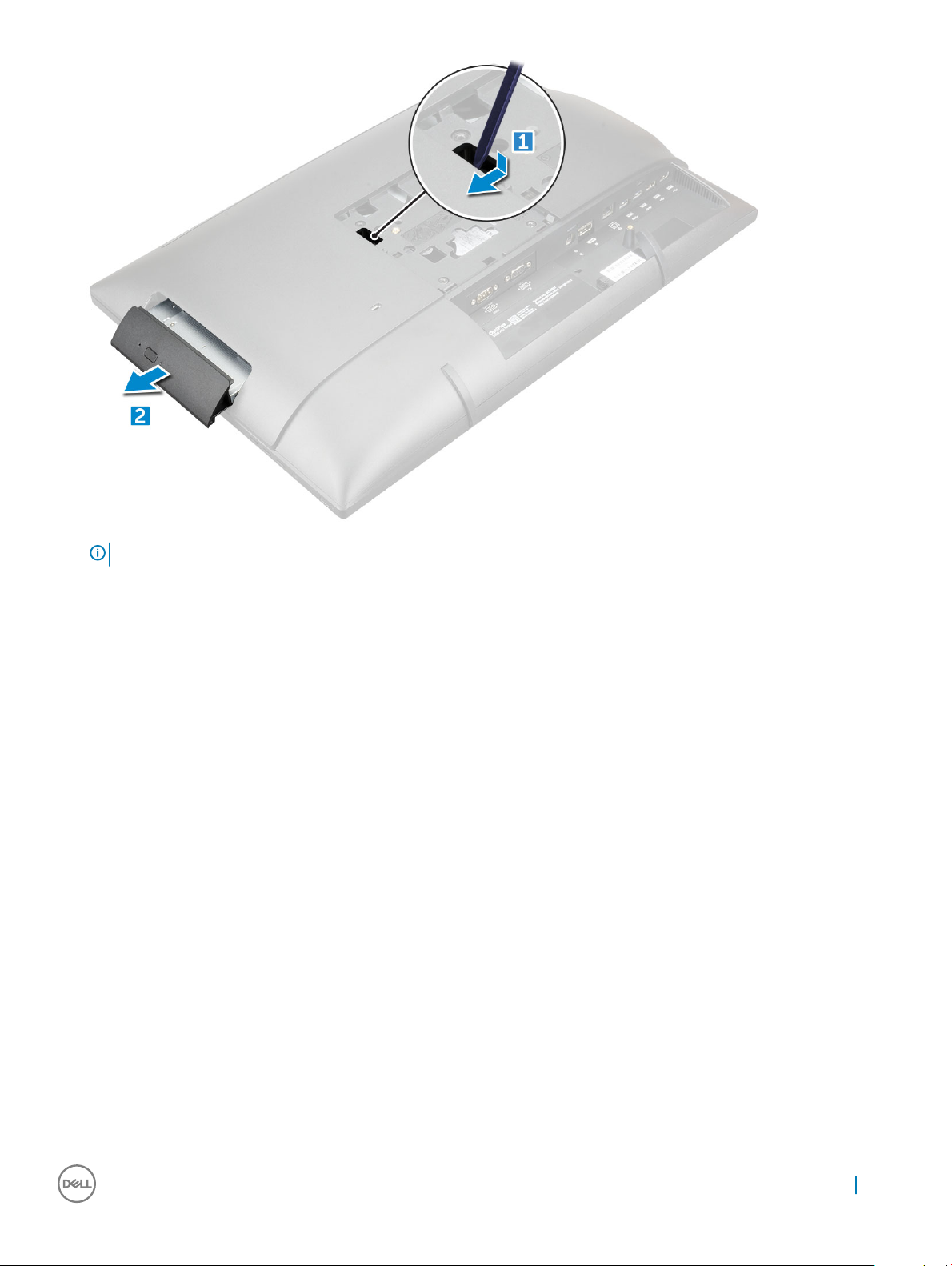
NOTE: If your system is not shipped with optical drive, to remove the metal tab follow step 3(a).
Installing optical drive
1 Insert the optical drive into the slot, until it snaps in.
2 Install the stand.
3 Follow the procedure in After working inside your computer.
Back cover
Removing back cover
1 Follow the procedure in Before working inside your computer.
2 Remove the:
a stand
b optical drive
3 Pry the edges and remove the back cover optical drive slot.
Removing and installing components
13
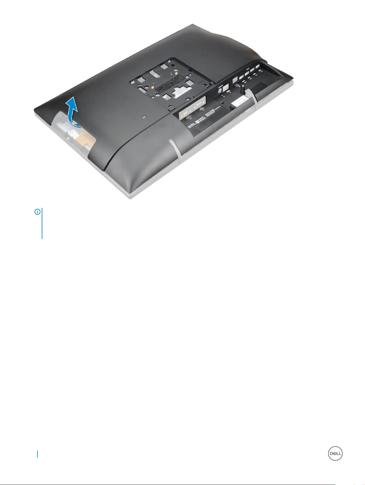
NOTE: On system with POGO Intrusion feature; after replacing the system board, it is very important that technicians
reassemble the back cover prior booting the system up to the SMMM service menu. The POGO intrusion feature can only
be enabled when the system is in service mode at SMMM. Once exited, the SMMM can no longer be triggered and a
replacement system board would be required.
Installing back cover
1 Align the notches on the back cover to the holes on the computer.
2 Press the back cover until it snaps on the computer.
3 Install the:
a optical drive
b stand
4 Follow the procedure in After working inside your computer.
Intrusion switch
Removing intrusion switch
1 Follow the procedure in Before working inside your computer.
2 Remove the:
a stand
b optical drive
c back cover
3 To remove intrusion switch from the back cover:
a Turn the holder clockwise direction [1].
b Lift the holder [2].
14
Removing and installing components
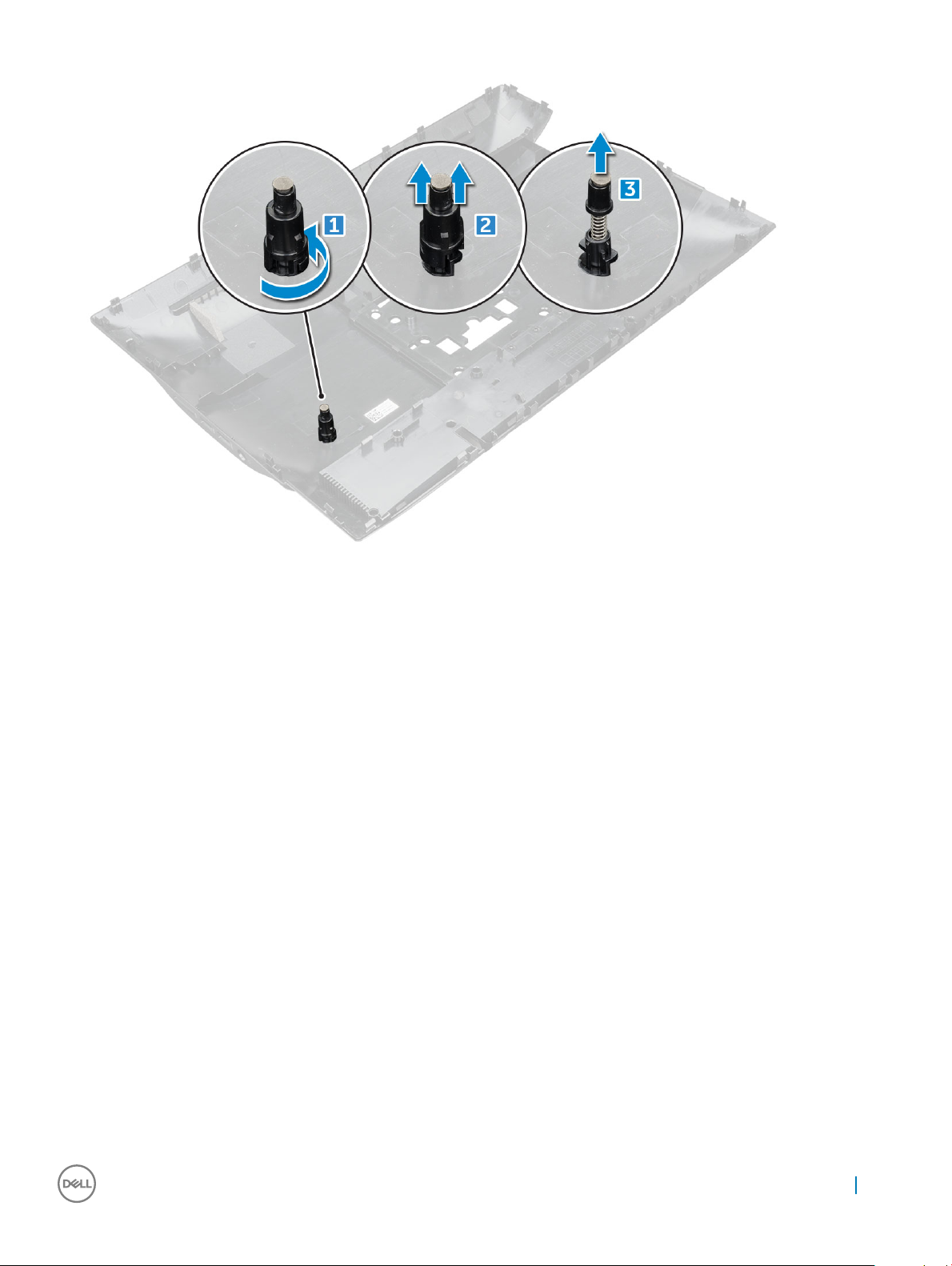
c Lift the intrusion switch [3].
Installing intrusion switch
1 Insert the switch on the holder on the back cover.
2 Plug the holder to intrusion switch
3 Replace the holder in direction.
4 Install the:
a back cover
b optical drive
c stand
5 Follow the procedure in After working inside your computer.
System board shield
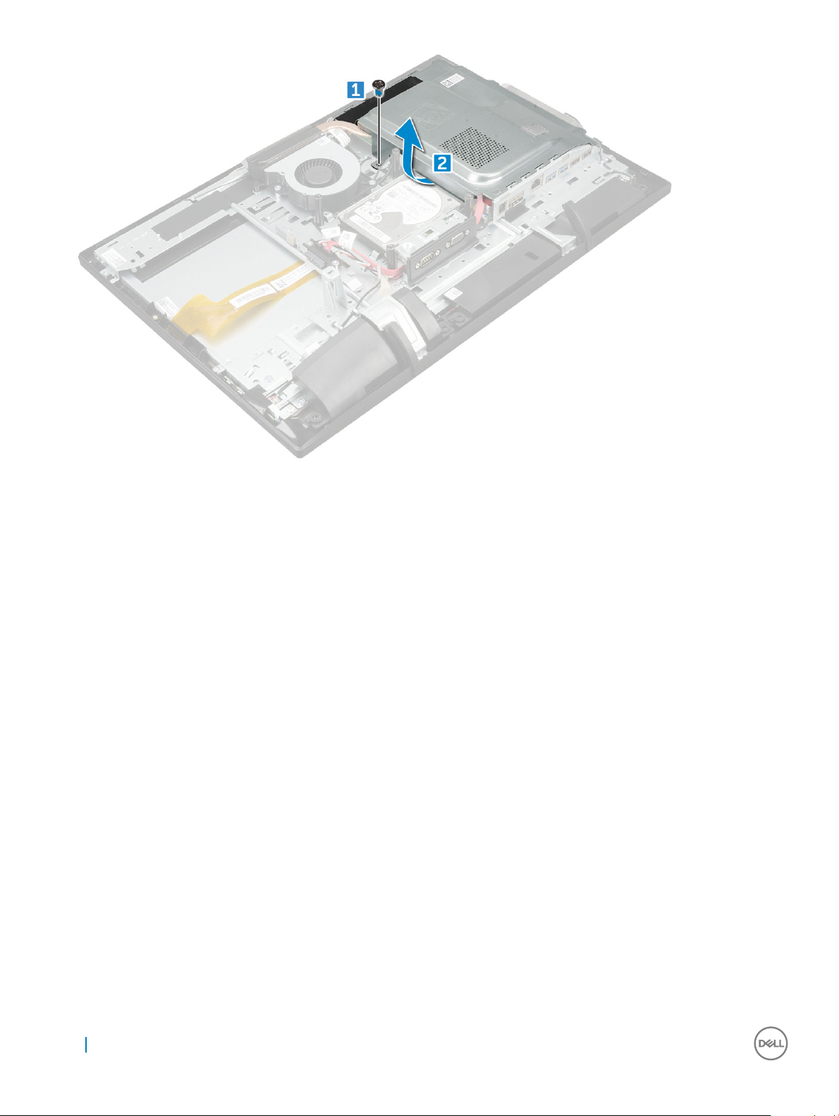
Removing system board shield
1 Follow the procedure in Before working inside your computer.
2 Remove the:
a stand
b optical drive
c back cover
3 To remove system board shield:
a Remove the M3 0.5x5 screw that secures system board shield to the computer [1].
b Lift the system board shield away from the computer [2].
Removing and installing components
15
Installing system board shield
1 Align the system board shield with the screw holder on the computer.
2 Replace M3 0.5x5 screw to secures the system board shield to the computer.
3 Install the:
a back cover
b optical drive
c stand
4 Follow the procedure in After working inside your computer.
Hard drive
Removing hard drive
1 Follow the procedure in Before working inside your computer.
2 Remove the:
a stand
b optical drive
c back cover
d system board shield
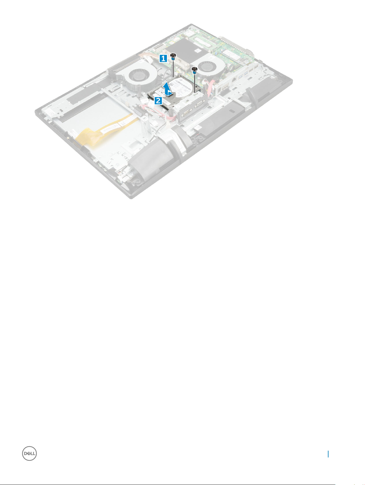
3 To remove hard drive:
a Remove the M3X3.5 screws that secure the hard drive to the computer [1].
b Slide and remove the hard drive from the computer [2].
16
Removing and installing components
Installing hard drive
1 Place the hard drive on the slot and slide it in to align with the screw holders and to connect it to the connector on the system board.
2 Replace the M3X3.5 screws to secure the hard drive on the computer.
3 Install the:
a system board shield
b back cover
c optical drive
d stand
4 Follow the procedure in After working inside your computer.
Cable holder
Removing cable holder
1 Follow the procedure in Before working inside your computer.
2 Remove the:
a stand
b optical drive
c back cover
d system board shield
e graphics card assembly
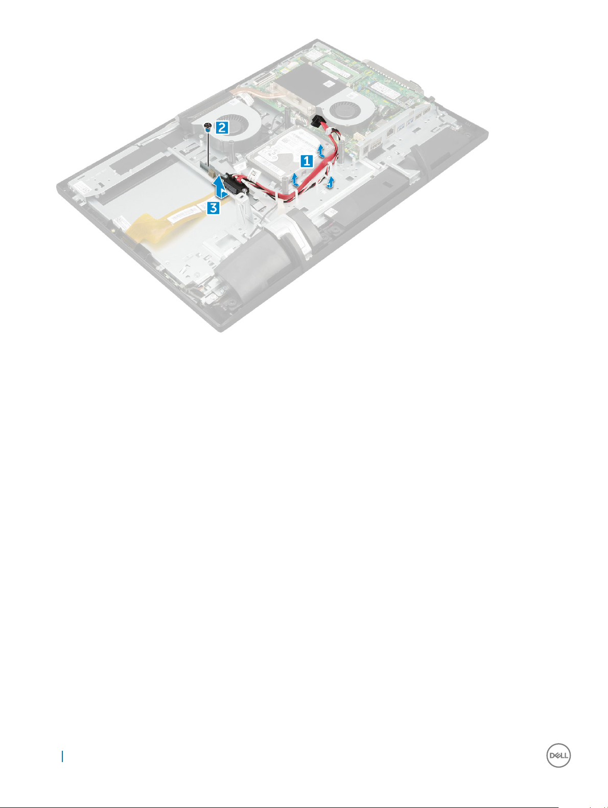
3 To remove cable holder:
a Disconnect and unroute VGA and SATA ODD cables from the system board [1]
b Remove the M2x2.5 screws that secure VGA and SATA ODD cables on the computer [2].
c Lift the cable holder away from the computer [3].
Removing and installing components
17
Installing cable holder
1 Route the VGA and SATA ODD cable the slot on the chassis.
2 Replace the M2x2.5 screws to secure the VGA and SATA ODD cable on the computer.
3 Connect the VGA and SATA ODD cables to the connector on the system board.
4 Install the:
a graphics card assembly
b system board shield
c back cover
d optical drive
e stand
5 Follow the procedure in After working inside your computer.
Memory modules
Removing memory module
1 Follow the procedure in Before working inside your computer.
2 Remove the:
a stand
b optical drive
c back cover
d system board shield
3 To remove memory module:
a Pry the retention clips away from the memory module until it pops-up [1].
b Lift the memory module from the connector [2].
18
Removing and installing components
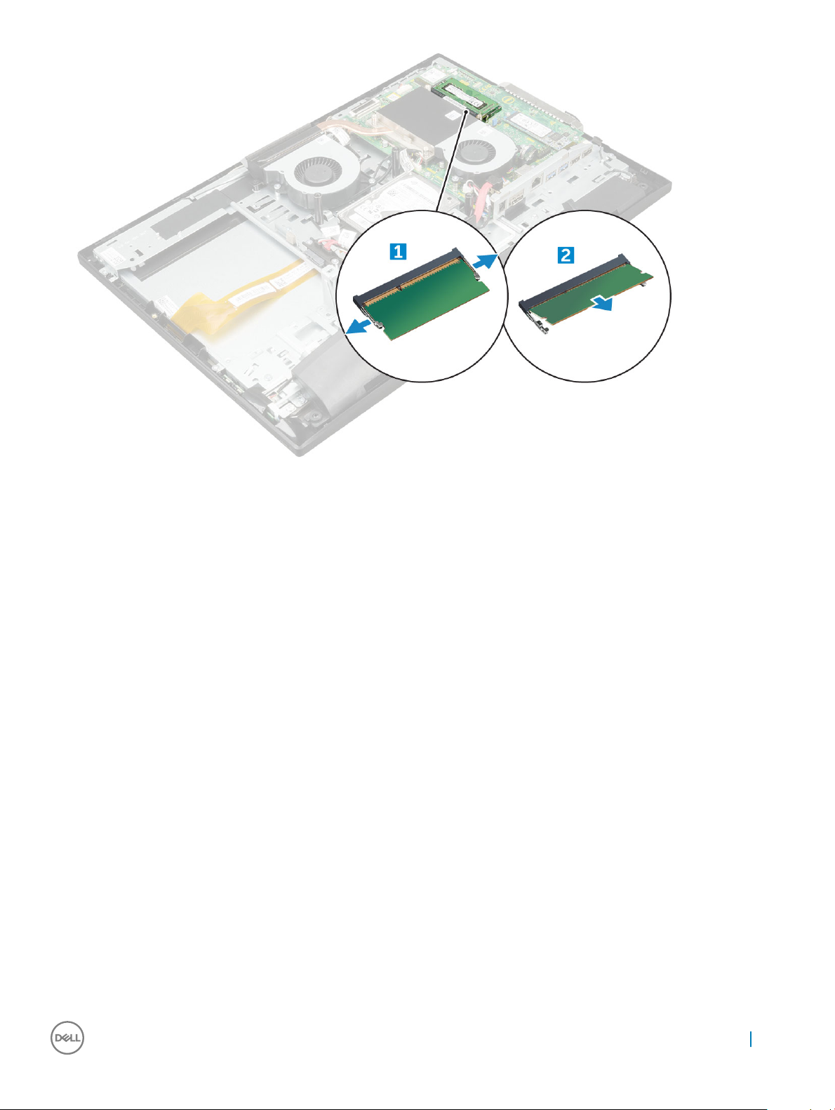
4 Perform the same steps to remove the second memory module.
Installing memory module
1 Insert the memory module into the slot and then press down until the clips snap-in.
2 Perform the same steps to insert the second memory module.
3 Install the:
a system board shield
b back cover
c optical drive
d stand
4 Follow the procedure in After working inside your computer.
Coin cell battery
Removing coin cell battery
1 Follow the procedure in Before working inside your computer.
2 Remove the:
a stand
b optical drive
c back cover
d system board shield
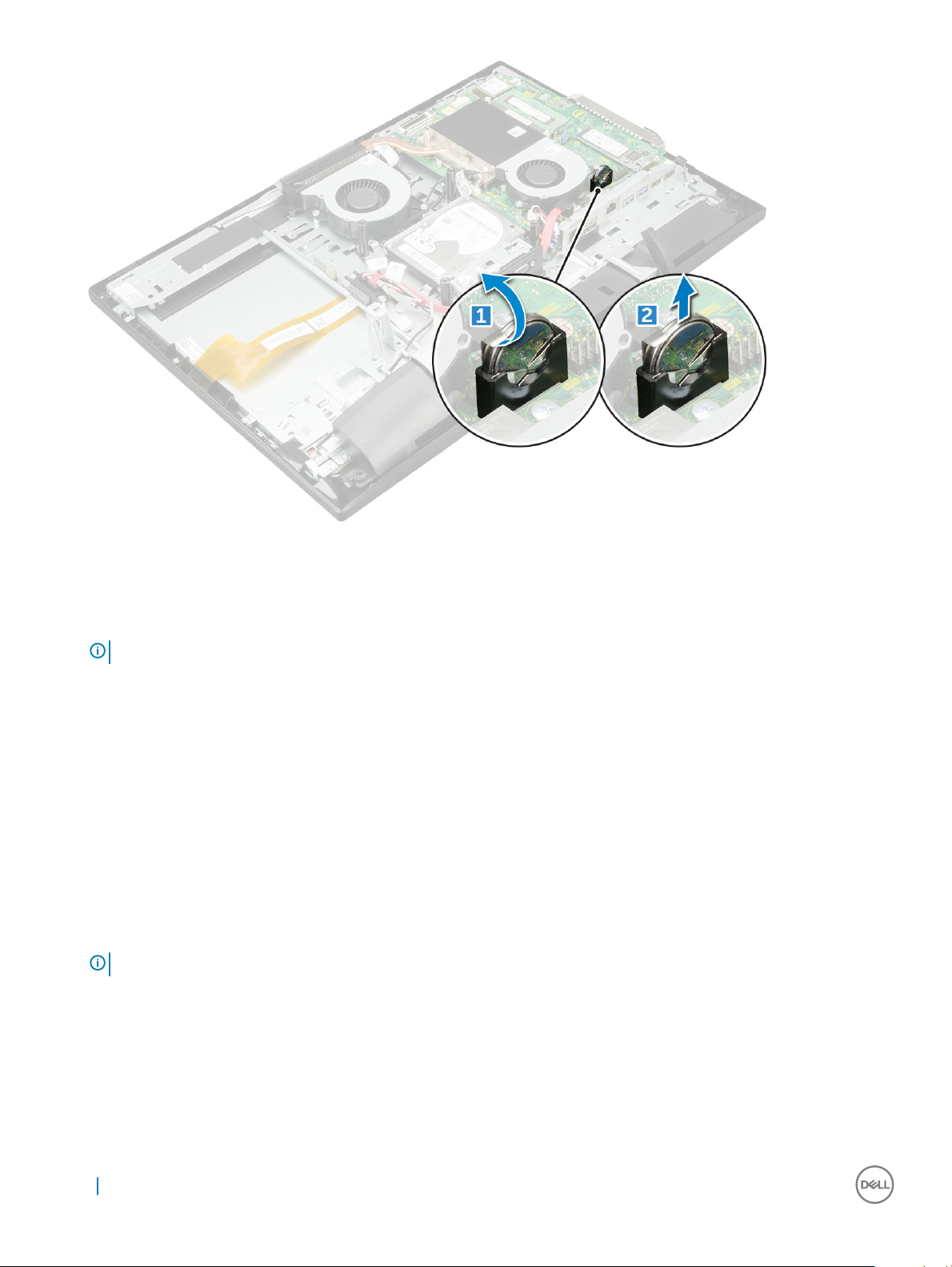
3 To remove coin cell battery:
a Push the metal latch to release the coin cell battery [1].
b Lift the coin cell battery from the computer [2].
Removing and installing components
19
Installing coin cell battery
1 Insert the coin cell battery into the slot on the system board, until it ts securely.
NOTE
: Insert the coin cell with the smooth side facing the metal tab.
2 Install the:
a system board shield
b back cover
c optical drive
d stand
3 Follow the procedure in After working inside your computer.
Solid State Drive — optional
Removing Solid State Drive (SSD) card
1 Follow the procedure in Before working inside your computer.
: If the system is shipped with SSD perform the following steps.
NOTE
2 Remove the:
a stand
b optical drive
c back cover
d system board shield
3 To remove SSD card:
a Remove the M2x2.5 screw that secures the SSD card to the system board [1].
b Lift the SSD card away from the connector [2].
20
Removing and installing components
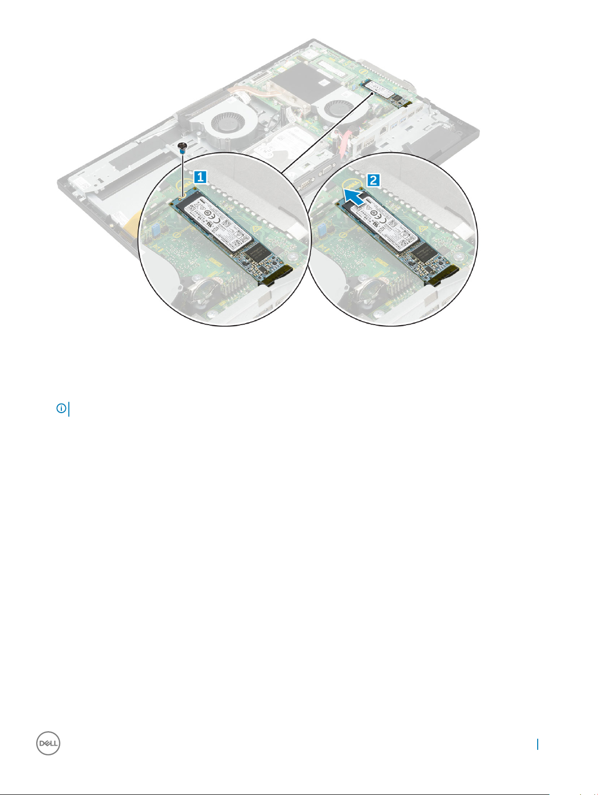
Installing Solid State Drive (SSD) card
1 Insert the SSD card to the connector on the system board.
NOTE
: If the system is shipped with SSD perform the following steps.
2 Replace the screw to secure the SSD card to the system board.
3 Install the:
a system board shield
b back cover
c optical drive
d stand
4 Follow the procedure in After working inside your computer.
WLAN card
Removing WLAN card
1 Follow the procedure in Before working inside your computer.
2 Remove the:
a stand
b optical drive
c back cover
d system board shield
3 To remove WLAN card:
a Disconnect the antenna cables from the connectors on the WLAN card [1].
b Remove the M2x 2.5 screw that secures the WLAN card to the system board [2].
Removing and installing components
21
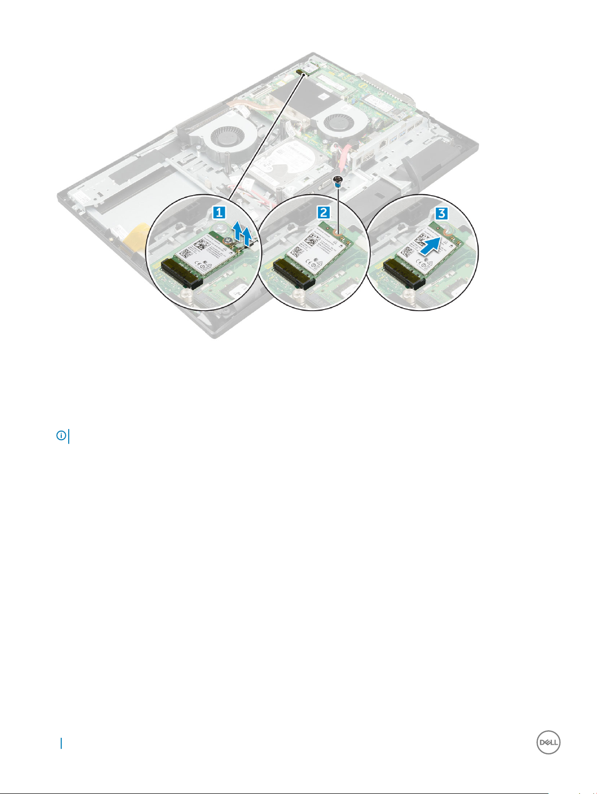
c Hold the WLAN card, and pull it from the connector on the system board [3].
Installing WLAN card
1 Align and then insert the WLAN card to the connector on the system board.
2 Replace the M2x2.5 screw to secure the WLAN card to the system board.
NOTE
: Best practise: Connect the cables and then insert the card into the slot.
3 Connect the antenna cables to the connectors on the WLAN card.
4 Install the:
a system board shield
b back cover
c optical drive
d stand
5 Follow the procedure in After working inside your computer.
Heat sink
Removing heat sink
1 Follow the procedure in Before working inside your computer.
2 Remove the:
a stand
b optical drive
c back cover
d system board shield
3 To remove heat sink:
22
Removing and installing components
 Loading...