

Page 1

Dell™ OpenManage™ Baseboard
Management Controller Utilities
User’s Guide
www.dell.com | support.dell.com
Page 2

Notes and Notices
NOTE: A NOTE indicates important information that helps you make better use of
your computer.
NOTICE: A NOTICE indicates either potential damage to hardware or loss of data
and tells you how to avoid the problem.
____________________
Information in this document is subject to change without notice.
© 2007 Dell Inc. All rights reserved.
Reproduction in any manner whatsoever without the written permission of Dell Inc. is strictly forbidden.
Trademarks used in this text: Dell, the DELL logo, OpenManage, PowerVault, PowerConnect, and
PowerEdge are trademarks of Dell Inc.; Microsoft, Windows, Windows Server and M-DOS are either
trademarks or registered trademarks of Microsoft Corporation in the United States and/or other
countries; Red Hat and Red Hat Enterprise Linux are registered trademarks of Red Hat Corporation;
SUSE is a registered trademark of Novell, Inc.; Intel is a registered trademark of Intel Corporation.
Other trademarks and trade names may be used in this document to refer to either the entities claiming
the marks and names or their products. Dell Inc. disclaims any proprietary interest in trademarks and
trade names other than its own.
August 2007
Page 3

Contents
1 Introduction . . . . . . . . . . . . . . . . . . . . . . . . 9
What’s New in BMC Management Utility 3.0 . . . 10
Supported Systems
. . . . . . . . . . . . . . . . . . . 10
BMC Configuration and Management Tasks
Configuring the BMC
Managing the System Using BMC
BMC Action on Event
Basic BMC Alerting Over a LAN
IPMI Shell Over a LAN
IPMI Shell Over the Serial Cable
SOL Proxy Over a LAN
. . . . . . . . . . . . . . . . 12
. . . . . . . . . 12
. . . . . . . . . . . . . . . 14
. . . . . . . . . . 14
. . . . . . . . . . . . . . . 15
. . . . . . . . . . 17
. . . . . . . . . . . . . . . 19
BMC Configuration and Management Tools
Using the Remote Access Configuration
Utility
. . . . . . . . . . . . . . . . . . . . . . . . 21
Using Deployment Toolkit
Using the BMC Management Utility
Using Server Administrator
Other Dell Documents You May Need
Obtaining Technical Assistance
. . . . . . . . . . . . . 21
. . . . . . . . 21
. . . . . . . . . . . . 22
. . . . . . . . . 22
. . . . . . . . . . . . 23
. . . . . . 12
. . . . . . 21
Contents 3
Page 4

2 Configuring Your Managed System . . . . . 25
BIOS Configuration . . . . . . . . . . . . . . . . . . . 25
Configuring System BIOS in
Dell PowerEdge™ x8xx/x9xx Systems
Configuring System BIOS in
Dell PowerEdge™ x9xx and xx0x Systems
Using BIOS Console Redirection With
SOL Proxy
. . . . . . . . . . . . . . . . . . . . . . 29
. . . . . . . 26
. . . . . 27
Baseboard Management Controller Configuration
. . . 29
Entering the Remote Access Configuration
. . . . . . . . . . . . . . . . . . . . . . . . 30
Utility
Remote Access Configuration Utility
. . . . . . . . . . . . . . . . . . . . . . . 30
Options
Configuring Your BMC Using the
Deployment Toolkit Utility
. . . . . . . . . . . . . . . . 36
Installation and Setup for
Microsoft Windows PE Operating Systems
. . . . 37
Creating a Bootable
Windows PE 2005 ISO Image
. . . . . . . . . . . . 38
Creating a Bootable
Windows PE 2.0 ISO Image
. . . . . . . . . . . . 40
Installation and Setup for
Linux Operating Systems
Basic configuration
. . . . . . . . . . . . . . 41
. . . . . . . . . . . . . . . . 42
Configuring Your BMC Using
Server Administrator
Using Dell Remote Access Controller 5
. . . . . . . . . . . . . . . . . . 45
. . . . . . 47
3 Using the BMC Management Utility . . . . 49
4 Contents
Installing the BMC Management Utility . . . . . . . . 50
Installation Prerequisites
Supported Operating Systems
. . . . . . . . . . . . . . 50
. . . . . . . . . . . 51
Page 5

Installation Procedures . . . . . . . . . . . . . . . . . 52
Installing on Systems Running Supported
Windows Operating Systems
. . . . . . . . . . . 52
Uninstalling on Systems Running Supported
Windows Operating Systems
. . . . . . . . . . . 53
Installing on Systems Running Supported
Linux Enterprise Operating Systems
. . . . . . . . 54
Uninstalling on Systems Running Supported
Linux Enterprise Operating Systems
. . . . . . . . 55
IPMI Shell
. . . . . . . . . . . . . . . . . . . . . . . . 55
Using IPMI Shell
. . . . . . . . . . . . . . . . . . 57
IPMI Shell Command Syntax
IPMI Shell Global Options
IPMI Shell Commands
SOL Proxy
. . . . . . . . . . . . . . . . . . . . . . . . 76
Using SOL Proxy
. . . . . . . . . . . . . . . . . . 78
Using SOL proxy in command mode
Configuring the SOL Proxy Configuration File
IPMItool
. . . . . . . . . . . . . . . . . . . . . . . . . 93
IPMItool Command for Dynamic Entry on the
DNS Server When DRAC is Not Present
4 Known Issues and
Frequently Asked Questions
Known Issues . . . . . . . . . . . . . . . . . . . . . . 103
General Issues
SOL Proxy Issues
IPMI Shell Issues
. . . . . . . . . . . . . . . . . . . 103
. . . . . . . . . . . . . . . . . . 103
. . . . . . . . . . . . . . . . . 104
. . . . . . . . . . . . 57
. . . . . . . . . . . . . 58
. . . . . . . . . . . . . . . 64
. . . . . . . . 88
. . . . . 90
. . . . . . 96
. . . . . . . . . 103
Frequently Asked Questions
. . . . . . . . . . . . . . 104
Contents 5
Page 6

A BMC Management Utility
Error Codes
. . . . . . . . . . . . . . . . . . . . . . 107
B Terminal Mode Commands
. . . . . . . . . . 111
Configuring Terminal Mode . . . . . . . . . . . . 111
Using Terminal Mode
Security Information
Syntax
. . . . . . . . . . . . . . . . . . . . . . . . . . 113
Command Length
Character Support
Hex-ASCII Command Format
Text Command Format
Examples
. . . . . . . . . . . . . . . . . . . . . . 115
. . . . . . . . . . . . . . . . 112
. . . . . . . . . . . . . . . . . . . 112
. . . . . . . . . . . . . . . . . . 113
. . . . . . . . . . . . . . . . . 113
. . . . . . . . . . . . . . 114
. . . . . . . . . . . . . . . . . . 114
C Escape Key Sequences . . . . . . . . . . . . . 123
6 Contents
Page 7

D Serial Port Console Redirection . . . . . . 125
Serial Communication . . . . . . . . . . . . . . . . . 125
Console Redirection Via COM1
Console Redirection Via COM2
Serial Terminal Communication to
BMC or DRAC
. . . . . . . . . . . . . . . . . . . 126
. . . . . . . . . . 125
. . . . . . . . . . 125
SPCR Table
Serial Console redirection With SOL Proxy
. . . . . . . . . . . . . . . . . . . . . . . 126
. . . . . . 127
Configuring Linux for Serial Redirection
During Boot
Enabling Login to the Console After Boot
. . . . . . . . . . . . . . . . . . . . . 127
. . . . . 129
Glossary . . . . . . . . . . . . . . . . . . . . . . . . . . . . 133
Index
. . . . . . . . . . . . . . . . . . . . . . . . . . . . . . 153
Contents 7
Page 8

8 Contents
Page 9

Introduction
The Dell™ systems’ baseboard management controller (BMC) monitors the
system for critical events by communicating with various sensors on the
system board and sends alerts and logs events when certain parameters exceed
their preset thresholds. The BMC supports the industry-standard Intelligent
Platform Management Interface (IPMI) specification, enabling you to
configure, monitor, and recover systems remotely. The BMC provides the
following features:
• Access through the system’s serial port and integrated NIC
• Fault logging and SNMP alerting
• Access to the system event log (SEL) and sensor status
• Control of system functions including power on and power off
• Support that is independent of the system’s power or operating state
• Text console redirection for system setup, text-based utilities, and
operating system consoles
• Access to Linux Enterprise server serial console interfaces by using Serial
over LAN (SOL).
Dell provides several distinct utilities and programs for accessing the BMC to
perform management activities. The following BMC interfaces allow you to
configure and manage your system through the BMC:
• The BMC Management Utility allows remote, out-of-band LAN and/or
serial port power control, event log access, and console redirection.
• The Remote Access Configuration Utility enables configuring BMC in a
pre-operating system environment.
• The Dell OpenManage™ Deployment Toolkit SYSCFG utility provides a
powerful command line configuration tool.
• Dell OpenManage Server Administrator allows remote, in-band access to
event logs, power control, and sensor status information and provides the
ability to configure the BMC.
• Command Line Interface (CLI) tools provide a command line tool for sensor
status information, System Event Log (SEL) access, and power control.
Introduction 9
Page 10

Additionally, the BMC can be accessed by standard, off-the-shelf terminal or
terminal emulator utilities that allow access to sensor status information and
power control.
What’s New in BMC Management Utility 3.0
The BMC Management Utility (BMU) 3.0 has the following new features:
• IPMItool command line interface available for Dell x8xx, x9xx, and xx0x
systems running supported Microsoft
• New commands to manage the LCD display in
• New commands to monitor your system’s power.
• Added support for Windows Server
and Web editions.)
NOTE: Microsoft Windows Server 2008 is scheduled to be available in the first half
of 2008. For latest information, see
http://www.microsoft.com/windowsserver2008/default.mspx.
®
Windows® and Linux systems.
x9xx
and xx0x systems.
®
2008 (includes Standard, Enterprise,
Supported Systems
The BMC management features documented in this guide are supported on
the following Dell systems:
• 800
• 830
• 840
• 850
• 860
• SC1425
• SC1435
• 1800
• 1850
• 1855
• 1900
• 1950
10 Introduction
Page 11

• 1955
• 2800
• 2850
• 2900
• 2950
• 2970
• 6800
• 6850
• 6950
• T105
• R900
• Dell PowerVault™ NX1950
• PowerVault 100
• PowerVault 500
• PowerVault 600
NOTE: All references in this document to x9xx systems also apply to the
PowerVault NX1950, PowerVault 500, and PowerVault 600 systems. All references
to the PowerEdge 840 system also apply to the PowerVault 100 system.
Introduction 11
Page 12

BMC Configuration and Management Tasks
The following sections document the basic tasks needed to set up and
configure the BMC on a managed system in preparation for using the BMC
Management Utility. These basic tasks are:
• Configuring the BMC
• Managing the BMC
Configuring the BMC
To configure the BMC on a managed system in a pre-boot environment, you
can use:
• Dell Deployment Toolkit (DTK)
• Remote Access Configuration Utility
• Dell Remote Access Controller (DRAC) 5 graphical user interface (GUI)
• command line interface (CLI)
from a management station depending on the scope of your required
configuration tasks. Alternately, you can configure the BMC on a managed
system with a running operating system using the Server Administrator home
page GUI or CLI. See "Baseboard Management Controller Configuration" for
more information.
Managing the System Using BMC
To manage the BMC in a pre-boot environment, or to access the BMC of a
system, you can use the BMC Management Utility. See "Using the BMC
Management Utility." To configure the BMC on a system with a running
operating system or to perform everyday BMC management tasks, you can
use the GUI on the Server Administrator home page. See the Server
Administrator User’s Guide for more information about using Server
Administrator to manage your system’s BMC functions. Figure 1-1 shows the
configuration matrix for BMC.
12 Introduction
Page 13
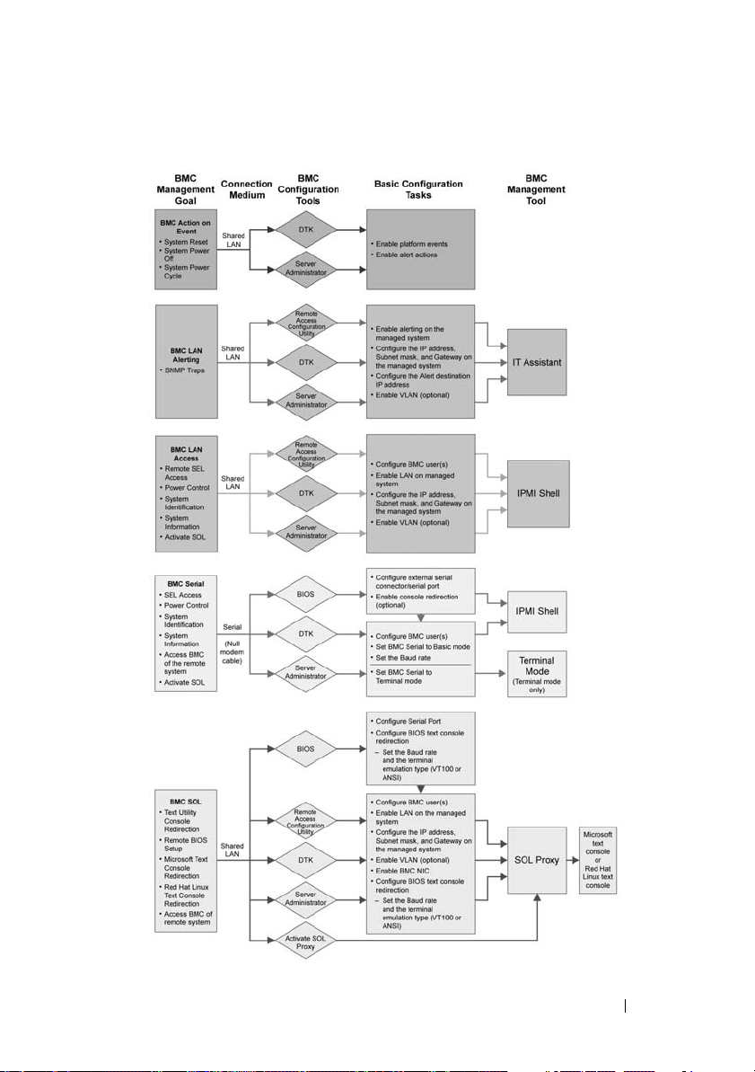
Figure 1-1. BMC Configuration Matrix
Introduction 13
Page 14

BMC Action on Event
If you plan to use your system’s BMC to perform actions when events occur,
you must follow the BMC Action on Event configuration guidelines listed in
Ta b l e 1 - 1 .
Table 1-1. BMC Action on Event Configuration Guidelines
Features Connection
Medium
•System
Reset
•System
Power Off
•System
Power
Cycle
LAN
BMC Configuration
To ol s
• Deployment Toolkit
(pre-operating system
environment)
• Server Administrator
Basic
Configuration
Ta sk s
•Enable
platform
events
• Enable alert
actions
Management
To ol s
NA
Basic BMC Alerting Over a LAN
If you plan to use your system’s BMC to send alerts (Platform Event Traps),
you must follow the BMC configuration guidelines listed in Table 1-2.
NOTE: The LAN-sharing depends on the NIC selection configuration option. The
available options are Shared and Failover, and if a RAC card is present, the additional
option available is Dedicated. See the NIC Selection option in the table in "Remote
Access Configuration Utility Options" section for more information on Shared, Failover,
and Dedicated.
NOTE: The Dedicated NIC selection option is available only if you are using Dell
Remote Access Controller (DRAC) 5.
14 Introduction
Page 15

Table 1-2. BMC LAN Alerting Configuration Guidelines
Features Connection
Medium
Platform
Event Alerts
(SNMP
Tr a ps )
LAN
BMC Configuration
To ol s
• Remote Access
Configuration
Utility (preoperating system
environment)
•Deployment
Toolkit (preoperating system
environment)
•Server
Administrator
Basic Configuration
Ta sk s
1
Configure NIC
Selection to
select Shared,
Failover, or
Dedicated
NOTE: This option is
available only on
Dell PowerEdge x9xx
and xx0x systems.
2
Configure the IP
address, Subnet
mask, and
Gateway on the
managed system
3
Configure the
VLAN (optional)
4
Enable alerting
5
Configure the
Alert destination
IP address
6
Configure the
Host Name
(optional)
Management
To ol s
IT Assistant
IPMI Shell Over a LAN
Table 1-3 lists the actions you can perform, if you plan to use the BMC
Management Utility’s IPMI Shell or IPMItool to access your system’s BMC
over a LAN.
Introduction 15
Page 16

Table 1-3. BMC LAN Access Configuration Guidelines
Features Connection
Medium
• Remote SEL
LAN
access
• Power control
•System
identification
•Sensor
information
BMC Configuration
To ol s
• Remote Access
Configuration
Utility (preoperating system
environment)
•Deployment
Toolkit (preoperating system
environment)
•Server
Administrator
Basic Configuration
Tas k s
1
Enable IPMI over
LAN on the
managed system
2
Configure NIC
selection to
select Shared,
Failover, or
Dedicated
NOTE: This
option is
available only on
Dell PowerEdge
x9xx and xx0x
systems.
3
Configure the
IP address,
Subnet mask,
and Gateway on
the managed
system
4
Configure IPMI
encryption key
(optional)
NOTE: This
option is
available only on
Dell PowerEdge
x9xx and xx0x
systems.
5
Configure VLAN
(optional)
6
Configure BMC
users
Management
Tools
IPMI Shell
16 Introduction
Page 17

IPMI Shell Over the Serial Cable
If you plan to use the BMC Management Utility’s IPMI Shell to access your
system’s BMC over a serial cable, you must follow the BMC configuration
guidelines listed in Table 1-4.
NOTE: Console redirection does not apply to BMC when using the serial interface.
Table 1-4. BMC Serial Configuration Guidelines
Features Connection
Medium
• Interactive
mode
• Remote SEL
access
• Power control
•System
identification
•System
information
• Access the
BMC of the
remote system
Accessed
through
the serial
channel by
using a
null
modem
cable
BMC Configuration
Tools
• BIOS (preoperating
system
environment)
•Deployment
Toolkit (preoperating
system
environment)
• Server
Administrator
(to enable BMC
serial only)
Basic
Configuration
Tas ks
1
Configure Serial
Port 1 to BMC
Serial
NOTE: This
option is
available only
on Dell
PowerEdge
x8xx systems.
2
Configure
External Serial
Connector to
Remote Access
NOTE: This
option is
available only
on Dell
PowerEdge
x9xx and xx0x
systems.
Management
To ol s
• IPMI Shell
(Basic
mode)
• Terminal
emulation
(Terminal
mode
only)
Introduction 17
Page 18

Table 1-4. BMC Serial Configuration Guidelines (continued)
Features Connection
Medium
•System
information
• Access the
BMC of the
remote system
BMC Configuration
To ol s
Basic
Configuration
Ta sk s
3
Set Serial baud
rate to match
the rate to be
used by the
management
tool
4
Set BMC Serial
Connection
Mode to Basic
for IPMI Shell
or Terminal for
Terminal
emulation
5
Configure BMC
users
Management
Tools
18 Introduction
Page 19

SOL Proxy Over a LAN
If you plan to use the BMC Management Utility’s SOL Proxy to access your
system’s console over a LAN, you must follow the BMC configuration
guidelines listed in Table 1-5.
Table 1-5. BMC SOL Configuration Guidelines
Features Connection
Medium
• Text Utility
console
redirection
• Remote
BIOS setup
• Microsoft
text
console
redirection
• Linux text
console
redirection
LAN
BMC Configuration
To ol s
• BIOS (preoperating system
environment)
• Remote Access
Configuration
Utility (preoperating system
environment)
• Deployment
Toolkit (preoperating system
environment)
• Server
Administrator
Basic Configuration
Ta sk s
1
Configure Serial
Port 1 to BMC
NIC
NOTE: This
option is available
only on Dell
PowerEdge x8xx
systems.
2
Configure BIOS
console
redirection to
Serial Port 1.
NOTE: This
option is available
only on Dell
PowerEdge x9xx
systems.
3
Configure
Console
Redirection to
On with Console
Redirection via
COM2
NOTE: This
option is available
only on Dell
PowerEdge x9xx
and xx0x systems.
Management
Tools
•SOL
Proxy
• IPMI
Shell
Introduction 19
Page 20

Table 1-5. BMC SOL Configuration Guidelines (continued)
Features Connection
Medium
• Force a
reboot on a
remote
system and
activate
console
redirection
• Access
BMC of
the remote
system
BMC Configuration
To ol s
Basic Configuration
Ta sk s
4
Configure other
Console
Redirection
parameters, such
as baud rate,
emulation type,
and so on.
5
Enable IPMI over
LAN on the
managed system
6
Configure the IP
address, Subnet
mask, and
Gateway on the
managed system
7
Configure IPMI
encryption key
(optional)
NOTE: This
option is
available only on
Dell PowerEdge
x9xx and xx0x
systems.
8
Configure VLAN
(optional)
9
Configure BMC
users
Management
Tools
20 Introduction
Page 21

BMC Configuration and Management Tools
Using the Remote Access Configuration Utility
The Remote Access Configuration Utility provides basic BMC setup and
configuration functions that can be accessed during system boot. Use the
Remote Access Configuration Utility for initial BMC setup and configuration
only. For advanced configuration tasks, you must use the Deployment Toolkit
SYSCFG utility or Server Administrator Version 2.0 or later.
NOTE: The Remote Access Configuration Utility is called the BMC Setup Module in
the Dell PowerEdge x8xx systems.
Using Deployment Toolkit
The Deployment Toolkit (DTK) SYSCFG utility provides a powerful
Microsoft Windows Preinstallation Environment (PE) and Linux
command
an initial deployment. Use the DTK SYSCFG utility to set all supported
BMC features. Additionally, you can use the Deployment Toolkit utilities to
capture and replicate system settings on similar systems. See "Configuring
Your BMC Using the Deployment Toolkit Utility" on page 36 for more
information on how to install and set up the DTK SYSCFG utility.
Using the BMC Management Utility
The BMC Management Utility provides a command-line interface to your
remote management station to manage BMC-supported functions. Use the
BMC Management Utility to manage your BMC from a remote management
station and as your managed system’s emergency management console. The
utility gives you the option of using either a command line interface (IPMI
Shell) or a SOL Proxy to access and manage the BMC. To use the BMC
Management Utility, you must perform the following tasks:
• Configure BMC using the Remote Access Configuration Utility, the DTK
• Install the BMC Management Utility on a management station.
See "Configuring Your Managed System" for instructions on configuring the
BMC on a managed system in preparation for using the BMC Management
Utility.
-line interface for locally configuring your system’s BMC as part of
SYSCFG utility, or Server Administrator.
Introduction 21
Page 22

Using Server Administrator
The Server Administrator provides a convenient and easy-to-use GUI for
remotely configuring or managing your system’s BMC on a system running a
supported operating system. You can use the Server Administrator to
configure the most relevant BMC features, such as Platform Event Filter
(PEF) parameters and alert destinations. Additionally, Server Administrator
can be used as a command line interface. Server Administrator requires that
the system has an operating system installed and functioning. As a result,
Server Administrator is best suited for everyday BMC management tasks, and
is not an option for performing pre-boot setup or accessing the BMC as an
emergency management console. To use Server Administrator, you must
perform the following tasks:
• Install Server Administrator on the managed system.
• Access the Server Administrator home page remotely or locally from a
supported browser on a management station.
• Configure BMC remotely or locally on the managed system.
See the Dell OpenManage™ Server Administrator User’s Guide and Command
line Interface User’s Guide on the Dell Support website at support.dell.com,
the Dell Systems Documentation CD, or the Dell Systems Management Tools
and Documentation DVD for more information about using Server
Administrator to configure and manage your system BMC.
Other Dell Documents You May Need
In addition to this User's Guide, you can find the following guides either on
the Dell Support website at support.dell.com or on the Dell Systems
Documentation CD and the Dell Systems Management Tools and
Documentation DVD:
•The
•The
•The
22 Introduction
Dell OpenManage Quick Installation Guide
information about installing the BMC Management Utility on a
management station.
Dell OpenManage Server Administrator User’s Guide
additional information about using Server Administrator to manage your
system’s BMC.
Dell OpenManage Deployment Toolkit User’s Guide
additional information about installing and using the DTK utilities.
provides additional
provides
provides
Page 23

• The
• The
• The Dell system User’s Guide provides supplemental information about
Additionally, the Dell OpenManage readme.txt file provides the latest
available information for the installation and operation of the programs and
utilities used to manage your system through the BMC. The readme is
available on the Dell Systems Console and Agent CD, the Dell Systems
Management Tools and Documentation DVD, and on the Dell Support
website at support.dell.com.
Dell OpenManage Deployment Toolkit Command Line Interface
Reference Guide
command-line options, suboptions, and arguments.
Dell OpenManage IT Assistant User’s Guide
about how to monitor and manage a large number of client and server
systems on a local area network (LAN) or wide area network (WAN).
configuring your BIOS settings with the System Setup Program, as well as
instructions for configuring your system to use console redirection.
provides a complete list of all valid BMC-related
provides information
Obtaining Technical Assistance
If at any time you do not understand a procedure described in this guide or if
your product does not perform as expected, help tools are available to assist
you. For more information about these help tools, see "Getting Help" in your
system's Installation and Troubleshooting Guide or the Hardware Owner’s
Manual.
Additionally, Dell Enterprise Training and Certification is available; see
www.dell.com/training for more information. This service may not be offered
in all locations.
Introduction 23
Page 24

24 Introduction
Page 25

Configuring Your Managed System
Before using the BMC Management Utility, configure certain items, such as
the necessary system BIOS, network, Intelligent Platform Management
Interface (IPMI) encryption key, and serial connection settings, depending on
the functionality to be performed, to enable access to the BMC.
NOTE: The IPMI encryption key is a public key that is used to generate an
encryption key for use between the firmware and the application.
In addition, to utilize the BMC Management Utility IPMI serial functions,
you must have a working connection between the management station and
the correct serial I/O port of the target BMC, using a null modem cable.
This section describes the basic procedures you must perform to prepare your
BMC to be accessed and managed using the BMC Management Utility.
The following procedures are described:
• BIOS Configuration
• Baseboard Management Controller Configuration
• Configuring your BMC with the Dell™ OpenManage™ Deployment
ToolKit (DTK) SYSCFG utility
• Configuring your BMC with Dell OpenManage Server Administrator
BIOS Configuration
For most configurations, you must configure the serial port settings and the
console redirection settings in your system BIOS before you can use the BMC
Management Utility. To configure the necessary system BIOS setting, your
must enter the System Setup Program. The BIOS settings can also be
configured using the Deployment Toolkit or the
NOTE: For more information about configuring BIOS settings, see your system
User’s Guide.
Configuring Your Managed System 25
Server Administrator.
Page 26

Configuring System BIOS in Dell PowerEdge™ x8xx/x9xx Systems
1
Turn on or restart your system.
2
Press <F2> immediately after you see the following message:
<F2> = Setup
The
System Setup
NOTE: If your operating system begins to load before you press <F2>, allow
the system to finish booting, and then restart your system and try again.
3
Use the up- and down-arrow keys to navigate to the
field and press <Enter>.
4
Use the up- and down-arrow keys to navigate to the
press <Enter>.
5
Use the space bar to select the serial port option.
The options are
(if an optional RAC is installed in the system).
To use BMC, serial port 1 uses the
can be through the serial port or the integrated shared NIC. RAC control
uses only the
when Console Redirection is set to use serial port 1.
a
Select
BMC Serial
serial cable connection.
b
Select
BMC NIC
access the BMC over a shared LAN.
6
Press <Enter> to return to the
7
Use the up- and down-arrow keys to navigate to the
field and press <Enter>.
8
Use the up- and down-arrow keys to navigate to the
option and then use the space bar to set the console redirection feature to
Serial Port 1
9
Use the up- and down- arrow keys to navigate to the
option and then use the space bar to set the console failsafe baud rate,
if applicable.
screen appears.
Integrated Devices
Serial Port 1
COM1, COM3, BMC Serial, BMC NIC, Off
COM1
address and communication
COM1
address.
Off
and
COM3
are not available options
if you are planning to access the BMC through the
if you are using SOL proxy and are planning to
System Setup
screen.
Console Redirection
Console Redirection
. Optionally, you can also enable
Redirection after Boot.
Failsafe Baud Rate
field and
, and
RAC
26 Configuring Your Managed System
Page 27

10
Use the up- and down-arrow keys to navigate to the
Ty p e
option and then use the space bar to select either
Remote Terminal
VT 100/VT 200
ANSI, if applicable.
11
Press <Enter> to return to the
12
Press <Esc> to exit the System Setup program. The
System Setup
screen.
Exit
screen displays
the following options:
•
Save Changes and Exit
•
Discard Changes and Exit
•
Return to Setup
13
Choose the appropriate option and exit the system setup.
Configuring System BIOS in Dell PowerEdge™ x9xx and xx0x Systems
1
Turn on and restart your system.
2
Press <F2> immediately after you see the following message:
<F2> = Setup
The
System Setup
NOTE: If your operating system begins to load before you press <F2>, allow
the system to finish booting, and then restart your system and try again.
3
Use the up- and down-arrow keys to navigate to the
Communication
4
Use the spacebar to select the appropriate serial communication option.
5
Press <Enter> to select the appropriate option for Console Redirection.
The following options are available:
On without Console Redirection:
available for use by the operating system or applications. Console
redirection is disabled. This is the default option.
screen appears.
Serial
field and press <Enter>.
COM1 and COM2 are enabled and
or
On with Console Redirection via COM1:
When BIOS console
redirection is enabled through COM1, the COM1 port is not available to
applications through the operating system.
On with Console Redirection via COM2:
When BIOS console
redirection is enabled through COM2, the COM2 port is not available to
applications through the operating system.
Configuring Your Managed System 27
Page 28

Off:
COM1 and COM2 are both disabled and not available for use by the
operating system or applications. BIOS Console redirection is disabled.
NOTE: Select On with Console Redirection via COM2 to use Console
Redirection with SOL.
6
Use the up- and down-arrow keys to navigate to the
Communication
7
Use the spacebar to select the appropriate external serial communication
field and press <Enter>.
External Serial
option.
The available options are
The default option is
NOTE: Select Remote Access to access the BMC through the serial cable
connection. This option can be set to any value for using SOL and accessing
the BMC over LAN.
8
Press <Enter> to select.
9
If required, use the spacebar to navigate to and change the settings for
COM1, COM2
COM1
.
, and
Remote Access.
Redirection after Boot.
10
Use the up- and down-arrow keys to navigate to the
Failsafe Baud Rate
option and then use the space bar to set the console failsafe baud rate,
if applicable.
11
Use the up- and down-arrow keys navigate to the
option and then use the space bar to select either
Remote Terminal Type
VT 100/VT 200
if applicable.
12
Press <Enter> to return to the
13
Press <Esc> to exit the System Setup program. The
System Setup
screen.
Exit
screen displays
the following options:
•
Save Changes and Exit
•
Discard Changes and Exit
•
Return to Setup
or
ANSI,
NOTE: For most options, any changes that you make are recorded but do not take
effect until you restart the system.
NOTE: Press <F1> to display the help file for the System Setup program.
28 Configuring Your Managed System
Page 29

Using BIOS Console Redirection With SOL Proxy
Console redirection allows maintenance of a system from a remote location
by redirecting keyboard input and output through the serial port. Any
console-based feature or operating system can then be used to access the
server. DR-DOS, Linux (init 3) and Windows
Console (SAC) are examples of operating systems and consoles that can be
used to access the server.
By default, some operating systems, such as Windows Server
automatically configured to send text console output to the BIOS. Manual
configuration of the Redirection after Boot feature through the system BIOS
may not be visible to the operating system. This results in both, the operating
system feature and the BIOS redirection feature, being enabled. Depending
on the operating system and its setup, the results may vary. Dell recommends
the following steps as good practice:
DR-DOS: Do not configure DR-DOS for serial console output. Enable
console redirection after reboot in system BIOS.
Windows Special Administrative Console (SAC): Do not configure
Windows SAC for serial console redirection. Enable console redirection after
reboot in system BIOS.
Linux: Do not configure console redirection after rebooting the system BIOS.
Do the tasks listed in the "Installation and Setup for Linux Operating
Systems" section, to configure Linux for console redirection.
NOTE: See" Escape Key Sequences" for a list of keystrokes to be used for BIOS Setup
operations from a serial terminal.
®
Special Administrative
™
2003, are
Baseboard Management Controller Configuration
You can perform basic BMC configuration using the Remote Access
Configuration Utility during system startup. See Figure 2-1. For more
advanced configuration options, see the instructions for the DTK SYSCFG
utility in the Deployment Toolkit User’s Guide.
Configuring Your Managed System 29
Page 30
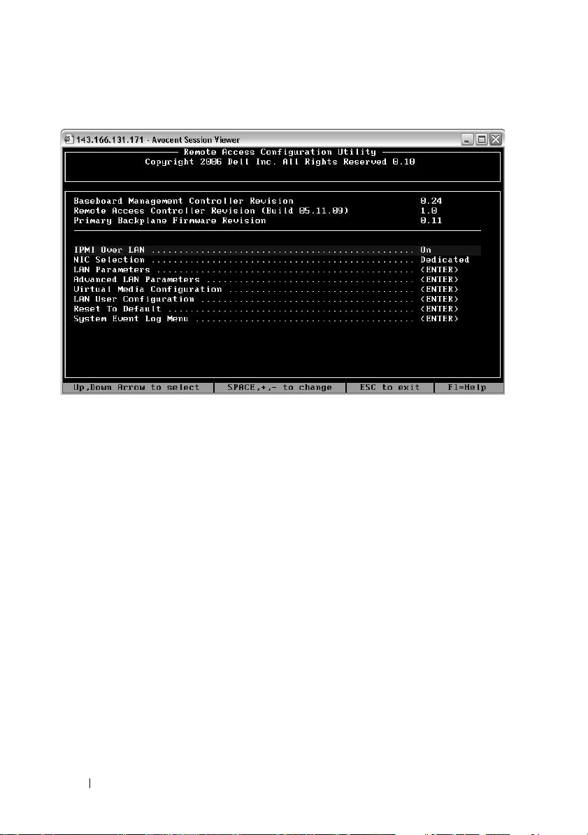
Figure 2-1. Remote Access Configuration Utility
Entering the Remote Access Configuration Utility
1
Turn on or restart your system.
2
Press <
If your operating system begins to load before you press <
allow the system to finish booting, and then restart your system and try
again.
Ctrl-E
> when prompted after POST.
Crtl-E
>,
Remote Access Configuration Utility Options
Table 2-1 lists the Remote Access Configuration Utility options and shows
how to configure the BMC on a managed system. After entering all settings,
press <Esc> and select one of the following:
•
Save Changes and Exit—
Configuration Utility.
•
Discard Changes and Exit
Configuration Utility.
•
Return to Setup
30 Configuring Your Managed System
—Continue using the Remote Access Configuration Utility.
Keep all entries made in the Remote Access
—Undo all entries made in the Remote Access
Page 31

Table 2-1. Remote Access Configuration Utility
Option Description
IPMI Over LAN
NIC Selection
NOTE: This option is
available only on Dell
PowerEdge x9xx and xx0x
systems.
Enables or disables the out-of-band LAN channel access
to the shared network controller.
Displays the configuration option.
•Shared
Select this option to share the network interface with
the host operating system. The remote access device
network interface is fully functional when the host
operating system is configured for NIC teaming.
The remote access device receives data through NIC 1
and NIC 2, but transmits data only through NIC 1.
If NIC 1 fails, the remote access device will not be
accessible.
NOTE: The NIC 2 is not available on the PowerEdge
1900 system.
• Failover
Select this option to share the network interface with
the host operating system. The remote access device
network interface is fully functional when the host
operating system is configured for NIC teaming.
The remote access device receives data through NIC 1
and NIC 2, but transmits data only through NIC 1.
If NIC 1 fails, the remote access device fails over to
NIC 2 for all data transmission.
The remote access device continues to use NIC 2 for
data transmission. If NIC 2 fails, the remote access
device fails over all data transmission back to NIC 1.
NOTE: This option cannot be selected on the
PowerEdge 1900 system.
Configuring Your Managed System 31
Page 32

Table 2-1. Remote Access Configuration Utility (continued)
Option Description
• Dedicated
Select this option to enable the remote access device to
utilize the dedicated network interface available on the
Remote Access Controller (RAC). This interface is not
shared with the host operating system and routes the
systems management traffic to a separate physical
network, enabling it to be separated from the
application traffic.
NOTE: This option is available only on systems with a
DRAC installed.
LAN Parameters
RMCP+ Encryption Key
IP Address Source
Ethernet IP Address The static IP address of the BMC. This field is limited
NOTE: This option is available only on PowerEdge x9xx
and xx0x systems.
The Key is used to encrypt the IPMI sessions.
The encryption key is entered as a maximum of 20 pairs
of ASCII hexadecimal characters representing 20 bytes.
For example,
01FA3BA6C812855DA001FA3BA6C812855DA0A0A0.
Displays whether the network controller will be assigned
a Static IP address or a DHCP address.
to a maximum value of 255.255.255.255.
The following IPv4 rules apply:
• IP addresses cannot be
xxx
is between
• The first octet must be between
143.xxx.xxx.xxx
127.xxx.xxx.xxx
0-255
.
)
1-223
, where
(that is,
NOTE: IP address 169.254.0.2 subnet mask 255.255.0.0 is
returned when the BMC is unable to contact the DHCP
server.
MAC Address
This field is read-only.
Displays the network controller’s BMC MAC address.
32 Configuring Your Managed System
Page 33

Table 2-1. Remote Access Configuration Utility (continued)
Option Description
Subnet Mask
The subnet mask for the static IP address.
NOTE: IP address 169.254.0.2 subnet mask 255.255.0.0 is
returned when the BMC is unable to contact the DHCP
server.
Default Gateway
VLAN Enable
VLAN ID
The IP gateway for the static IP address.
Enables or disables the virtual LAN ID.
This field is read-only when VLAN Enable is set to off.
To enter a value, navigate to the VLAN ID field from
another field.
A valid value for the virtual LAN ID must be a number
from 1 to 4094.
NOTE: If you enter a value outside the specified range,
either 1 or 4094 is entered, whichever is closest.
VLAN
LAN Alert Enabled Enables or disables LAN alerting.
Alert Policy Entry 1 Enables or disables the first alert destination.
Alert Destination 1
This field is read-only when VLAN Enable is set to off.
Specifies the priority of the VLAN. The valid values
range from Priority 0 - Priority 7.
This field is read-only when LAN Alert Enabled is
set to off.
Enter the IP address of the first alert destination. Use
the Left or Right arrow keys to navigate to each octet.
Use the numeric keypad to enter each octet.
The following IPv4 rules apply:
• IP addresses cannot be
0-255
between
• The first octet must be between
143.xxx.xxx.xxx
• The last octet must not be
xxx.xxx.xxx.0
(i.e.
127.xxx.xxx.xxx
.
)
0
or
or
xxx.xxx.xxx.255
1-223
255
(i.e.
, where
)
xxx
is
Configuring Your Managed System 33
Page 34

Table 2-1. Remote Access Configuration Utility (continued)
Option Description
Host Name String
Specifies the managed system hostname used to
correlate Platform Event Traps to the system on which
they originate.
Use alpha-numerics, but no symbols (except ’-’) or
spaces.
Advanced LAN Parameters
NOTE: This option is available only on systems with a
DRAC installed.
Dedicated NIC Configuration Options
NIC
Auto-Negotiate
LAN Speed Setting
Enables or disables the NIC
Enables or disables Auto-Negotiation of the LAN Speed.
This field is read-only when Auto-Negotiate is set
to Enabled.
Set the LAN Speed Setting to 10 or 100 Mbps
LAN Duplex Setting
This field is read-only when Auto-Negotiate is set
to Enabled.
Sets the LAN communication method to Half or Full
Duplex.
DNS Configuration Options
DNS Servers from DHCP
on = IP addresses of the DNS Servers are assigned by
the DHCP
off = IP addresses of the DNS Servers are set manually
DNS Server 1
This field is read-only when DNS Servers from
DHCP is set to on.
Enter the IP Address of DNS Server 1
The following IPv4 rules apply:
• IP addresses cannot be
0-255
between
• The first octet must be between
143.xxx.xxx.xxx
• The last octet must not be
xxx.xxx.xxx.0
(i.e.
127.xxx.xxx.xxx
.
)
0
or
xxx.xxx.xxx.255
or
1-223
255
, where
xxx
is
(i.e.
)
34 Configuring Your Managed System
Page 35

Table 2-1. Remote Access Configuration Utility (continued)
Option Description
DNS Server 2
This field is read-only when DNS Servers from
DHCP is set to on.
Enter the IP Address of DNS Server 2
The following IPv4 rules apply:
Register RAC Name
Register RAC Name
• IP addresses cannot be
0-255
between
• The first octet must be between
143.xxx.xxx.xxx
• The last octet must not be
xxx.xxx.xxx.0
(i.e.
on = You may enter the Current DNS RAC Name.
This field is read-only when Register RAC Name is
127.xxx.xxx.xxx
.
)
0
or
xxx.xxx.xxx.255
set to off.
Enter the Current DNS RAC Name using 1-32 alphanumerics, spaces, and symbols. Press <Enter> to save
the value. Press <Esc> to exit the field without saving.
Domain Name from DHCP
Domain Name
Turns the domain name on or off.
This field is read-only when DNS Servers from
DHCP is set to on.
Enter the Domain Name using 1-64 alpha-numerics,
spaces, and symbols. Press <Enter> to save the value.
Press <Esc> to exit the field without saving.
Virtual Media
Configuration
Virtual Media
Virtual Flash
LAN User Configuration
NOTE: This option is available only on systems with a
DRAC installed.
Attaches or detaches a virtual media drive.
Enables or disables virtual flash memory.
Enables setting the user name, user password, user
privilege, and enables user access for user ID=2.
Account Access
Account Privilege
Enables or disables account privileges.
Sets the account to:
Admin, User, Operator, or No Access
Account User Name
Sets the account user name.
or
1-223
255
, where
xxx
is
(i.e.
)
Configuring Your Managed System 35
Page 36

Table 2-1. Remote Access Configuration Utility (continued)
Option Description
Enter Password
Confirm Password
Reset To Default
System Event Log Menu
Total System Event Log
Entries
View System Event Log
Clear System Event Log
NOTE: If the first integrated network interface controller (NIC 1) is used in an Ether
Channel team or link aggregation team, the BMC management traffic will not
function on PowerEdge x8xx systems. The NIC teaming option is supported only on
PowerEdge x9xx and xx0x systems. For more information about network teaming,
see the documentation for the network interface controller.
Enter the password for this Account User. You must
enter at least one non-null character.
Confirm the password you entered.
Clears the BMC settings and resets the BMC setting to
the defaults.
NOTICE: Resetting to factory defaults will restore
remote non-volatile settings.
Enables viewing and clearing the System Event Log (SEL).
A popup box will indicate that the SEL is being read.
Displays the number of records in the SEL.
Displays a record in the SEL, starting with the most
recent record. Enter a record number to view, using the
Advance to Entry field. Use the Right and Left
arrow keys to scroll up and down the SEL.
Erases all records in the SEL.
Configuring Your BMC Using the Deployment Toolkit Utility
The Dell OpenManage Deployment Toolkit SYSCFG utility includes a set of
Microsoft
deploying Dell systems. The Deployment ToolKit (DTK) SYSCFG utility is
specifically designed to address all necessary BMC configuration tasks using a
powerful and comprehensive command-line interface. This utility runs on
PowerEdge 1435SC and all supported PowerEdge x7xx, x8xx, x9xx and xx0x
systems.
36 Configuring Your Managed System
®
Windows PE and Linux-based utilities for configuring and
Page 37

To use the BMC Management Utility, configure your managed system with
the SYSCFG utility by performing the following tasks:
• Obtain the latest version of DTK from
support.dell.com
.
the Dell Support website at
• Create a BMC configuration CD containing a bootable image, and the
SYSCFG utility.
• Configure BMC Users.
• Configure BMC SOL access.
• Configure BMC IPMI serial access.
Installation and Setup for Microsoft Windows PE Operating Systems
NOTE: See the Deployment Toolkit User’s Guide for additional information about
installing and using the utilities, and the Deployment Toolkit Command Line
Interface Reference Guide for a complete list of valid options, suboptions, and
arguments for using the SYSCFG.EXE to configure and manage your BMC.
The DTK components are provided as a self-extracting zip file on the Dell
Support website at support.dell.com. The self-extracting file can be opened
on any system running a Microsoft Windows operating system, or it can be
extracted at the Windows Command Prompt (cmd.exe) using the
PKUNZIP.EXE utility (not supplied with the Deployment Toolkit). By
default, the dtk-2.X-winpe-AXX.exe files are extracted to the root directory of
your local hard drive, for example, C:\. This location can be changed by giving
a different path when extracting the file. Perform the following steps to
extract the DTK components to a workstation running Windows:
1
Download the DTK file
website at
support.dell.com
Windows operating system.
2
After the zip file downloads, double-click the file.
3
Click OK.
4
Click
Unzip
.
By default, the DTK files are unzipped to
located in the
located in the
C:\Dell\Toolkit\Tools
C:\Dell\drivers
dtk-2.X-winpe-AXX
.exe
from the Dell Support
and save it on a system running a supported
C:
\. The
SYSCFG.EXE
utility is
directory. Dell-provided drivers are
folder.
Configuring Your Managed System 37
Page 38

Creating a Bootable Windows PE 2005 ISO Image
NOTE: See "Creating a Bootable Windows PE 2.0 ISO Image" on page 40 for
information on creating a bootable CD for Windows PE 2.0.
Integration of DTK Directory Structure in the Windows PE Build
This task involves a five-step process:
Integrating DTK tools and scripts: Copy the folder
1
unzipped from the Dell-supplied zip file to
DellWinPEBuild,
the Dell-supplied file directly into the Windows PE build.
2
Installing necessary drivers into Windows PE: Execute
\Dell\Drivers\DRIVERINST.BAT
• Path to
DellWinPEBuild
with two required arguments:
• Path where the Dell-provided drivers are located. These drivers can be
found in the DTK zip file under the
3
Adding support for mass storage drivers into Windows PE:
NOTE: You must implement this step to ensure mass storage drivers are
installed into Windows PE.
In the
winpeoem.sif
file (available under
\Dell\drivers
I386\SYSTEM32
Windows PE directory), edit the following text to remove the semicolons
from the
names for the Dell
Oem Driver Params
-m
ass storage drivers:
section and append the directory
\Dell
folder.
that you
in your
or extract
OemDriverRoot=""
OemDriverDirs=MRAID, PERC4IM, PERC5, SAS5
NOTE: For your reference, a sample winpeoem.sif file is available under
\Dell\Toolkit\template\Configs.
4
Starting required services: The
started for RAID to function; the
mr2kserv
racsvc
service should be installed and
service should be installed and
started for RACADM to function. For details on how to start the required
services, see the sample
\Dell\Toolkit\template\Configs
NOTE: When booting the target system, ensure that the RAC and the
mr2kserv services are running.
winbom.ini
.
file under
38 Configuring Your Managed System
Page 39

5
Extracting the following files from your Windows Server 2003 product CD
to
\Dell\Toolkit\Tools
:
• rpcns4.dll
• rpcrt4.dll
• rpcss.dll
NOTE: The directory name should not have any spaces.
You can now customize the Windows PE according to your requirements.
Creating a Bootable CD
Use the following steps to create bootable media that can be used to
configure the BMC on a managed system:
Create a directory,
1
2
Insert the Windows OEM Preinstallation Kit (OPK) CD into your CD
WinPE_OPKTools
, on your hard drive.
drive.
3
Copy all CD files from the Windows PE directory to the
WinPE_OPKTools
4
Copy
factory.exe
the
WinPE_OPKTools
5
Remove the CD from the CD drive.
6
Create and name a directory on your development system hard drive.
directory.
and
netcfg.exe
directory.
from the
CD drive
\tools\x86 directory to
This is where the ISO file is stored.
7
Navigate to the
8
Run the following command:
WinPE_OPKTools
directory through a command prompt.
OSCDIMG -bETFSBOOT.COM -n <DELLWINPEBUILD>
ETFSBOOT.COM is part of the OPK tools and makes the Windows PE
CD bootable. The following command line creates a bootable ISO image
called Dellx86winpe.iso:
C:\WINPE_OPKTOOLS\OSCDIMG -bETFSBOOT.com -n
c:\DELLWINPEBUILD
C:\FINALBUILD\Dellx86winpe.iso
Configuring Your Managed System 39
Page 40

9
Copy the SYSCFG.EXE utility to the root of the directory.
10
After you create an ISO image, you can use any CD-burning software to
burn the image onto a CD.
You are now ready to use your bootable CD to configure the BMC on a
managed system. See the
Deployment Toolkit User’s Guide
for additional
information.
Creating a Bootable Windows PE 2.0 ISO Image
If you are using Windows PE 2.0, download
Installation Kit (WAIK) from the Microsoft website. By default, WAIK is copied
to the
C:\Program Files\Windows AIK
Integration of DTK Directory Structure in Windows PE Build
DTK provides a script, VPE_driverinst.bat, to pre-install the Dell drivers into
a base Windows PE 2.0 image offline. Use the following steps to execute
this script:
1
Open a command prompt on your system and change the directory to the
location of VPE_driverinst.bat. For example:
cd C:\Dell\Drivers\winpe2.x
Execute VPE_driverinst.bat with two required arguments
2
<WINPEPATH>
and
<DTKPATH>
VPE_driverinst.bat <WINPEPATH> <DTKPATH>
Windows Administrative
directory.
. For example:
Where
<WINPEPATH>
structure for Windows PE 2.0 and
i s t h e d e st in a ti o n p a th t o c re at e t h e d i re c to r y
<DTKPATH>
is the path to Dell
drivers in the extracted DTK toolkit. For example:
VPE_driverinst.bat C:\vistaPE_x86 C:\DELL\DRIVERS
NOTE: <WINPEPATH> is passed as the destination to the WAIK command
copype.cmd. The destination folder C:\vistaPE_x86 is created as part of the
process, and should not already exist.
40 Configuring Your Managed System
Page 41

Creating a Bootable CD
Use the following steps to create bootable media:
1
Click
Start
2
, navigate to
Click
Windows PE Tools Command Prompt
All Programs→ Microsoft Windows AIK
to open a command prompt
window.
3
Run the following command:
oscdimg -n -bc:\vistaPE_x86\etfsboot.com
c:\vistaPE_x86\ISO c:\vistaPE_x86\WinPE2.0.iso
This command creates a CD bootable ISO image called WinPE2.0.iso.
4
You can use any CD burning software to burn the image onto a CD.
You are now ready to use your bootable CD to configure the BMC on a
managed system. See the
Deployment Toolkit User’s Guide
for additional
information.
Installation and Setup for Linux Operating Systems
NOTE: See the Deployment Toolkit User’s Guide for additional information about
installing and using the utilities, and the Deployment Toolkit Command Line
Interface Reference Guide for a complete list of all valid options, suboptions, and
arguments for using the SYSCFG utility to configure and manage your BMC.
1
Obtain the ISO image of embedded Linux available on the Dell Support
website at
2
Burn the ISO image using any commonly available CD burning software.
support.dell.com
.
.
NOTE: When you create a bootable CD, this image is supplied to the CD burning
software along with the complete deployment directory structure, which includes
all necessary supporting files to perform the deployment.
3
The CD burning software creates an image of the self-bootable ISO image
and the deployment files on the CD.
4
Extract the contents of the ISO image to a folder on your hard drive.
5
Copy your custom scripts into the folder you created in step 4.
NOTE: Your scripts should also take care of copying miscellaneous items to
unlock the CD, so that the CD can be mounted and ejected as required by the
operating system’s installation process.
Configuring Your Managed System 41
Page 42

6
In
/mnt/cdrom/isolinux.cfg
, the cd install section points to your
customized start-up script.
NOTE: The scripts that you copy into the CD will be copied to and run from the
RAM disk. This task is done to ensure the CD is not locked. Ensure that your
sample scripts have valid path names.
7
Copy the directory structure created in your work station, into the root
folder that you created in "step 4".
8
This folder contains the DTK CD files necessary for operating system
installation, and files required for replication.
9
Use the
isolinux
utility to burn the contents of the folder you created in
"step 7" to a CD and make it bootable.
10
Your ISO image is ready for booting.
Basic configuration
Before you can use the BMC Management Utility to remotely manage the
BMC on a managed system, you must perform some basic configuration
tasks. The Deployment Toolkit SYSCFG utility provides a powerful
command-line interface for performing the following configuration tasks:
• Configuring BMC users for the managed system
• Configuring the BMC IP address for IPMI LAN access and SOL access for
the managed system
• Configuring the BMC serial channel for IPMI serial access for the
managed system
NOTE: See the Deployment Toolkit User’s Guide for additional information about
installing and using the Deployment Toolkit utilities, and the Command Line
Interface Reference Guide for a complete list of valid options, suboptions, and
arguments for using the SYSCFG utility to configure and manage your BMC.
42 Configuring Your Managed System
Page 43

Configuring New BMC Users
The BMC is configured by default with user ID 2 set to username: root and
password: calvin. It is highly recommended that you change the user name
and password when deploying your system.
1
Insert the bootable BMC configuration diskette or CD into the
appropriate drive of the system to be deployed and reboot the system.
2
To create a new user, at the command prompt, type:
syscfg username --userid=X --name=
name
where X is a number between 2–10 and
name
is an ASCII string of 16 or
fewer characters.
Press <Enter> to execute the command line options.
3
To enable the new user ID, at the command prompt, type:
syscfg useraction --userid=X --action=enable
Press <Enter> to execute the command line options.
4
To set the password for a BMC user, at the command prompt, type:
syscfg passwordaction --action=setpassword --userid=X -
-password=
where
PowerEdge
NOTICE: A password must be set for each BMC user. The BMC firmware
does not allow access to users with null user names or passwords.
password
password
x8xx
is an ASCII string of 16 or fewer characters for both
and
x9xx
systems.
Press <Enter> to execute the command-line options.
5
To configure BMC user privilege, at the command prompt, type:
syscfg lanuseraccess --usrprivlmt=bmcuserprivilege
where bmcuserprivilege=
user, operator,
administrator, noaccess
Press <Enter> to execute the command-line options.
Configuring Your Managed System 43
Page 44

Configuring the BMC IP Address
1
Insert the Deployment Toolkit CD into the appropriate drive of the
system to be deployed and reboot the system.
2
To configure the BMC IP address source for the LAN channel to DHCP, at
the command prompt, type:
syscfg lcp --ipaddrsrc=dhcp
Press <Enter> to execute the command line options.
For a complete list of valid options, suboptions, and arguments for
configuring the BMC LAN channel see the
Line Interface Reference Guide
3
To configure the BMC IP address source for the LAN channel to a static
IP address, at the command prompt, type:
syscfg lcp --ipaddrsrc=static --ipaddress=
.
Deployment Toolkit Command
XXX.XXX.XXX.XX
--subnetmask=
XXX.XXX.XXX
Press <Enter> to execute the command line options.
For a complete list of valid options, suboptions, and arguments for
configuring the BMC LAN channel see the
Line Interface Reference Guide
XXX.XXX.XXX.X
.X
.
--gateway=
Deployment Toolkit Command
44 Configuring Your Managed System
Page 45

Configuring the BMC Serial Channel Access
1
Insert the bootable diskette or CD into the appropriate drive of the system
to be deployed, and reboot the system.
2
To configure the serial port for BMC, at the command prompt, type:
syscfg scp --connectionmode=basic -msgcommbitrate=
where
XXXXX
Press <Enter> to execute the command line options.
3
To configure the terminal mode for BMC, at the command prompt, type:
syscfg scp --connectionmode=terminal -msgcommbitrate=
where
XXXXX
Press <Enter> to execute the command line options.
For a complete list of valid options, suboptions, and arguments for
configuring the BMC serial channel, see the
Line Interface Reference Guide
is the baud rate in bps.
is the baud rate in bps.
XXXXX
XXXXX
Deployment Toolkit Command
.
Configuring Your BMC Using Server Administrator
You can also configure the BMC options using Server Administrator Version 5.3,
which is a one-to-one systems management software program that must be
installed on the managed system. Once installed, you can remotely access
Server Administrator from a management station with a supported browser to
perform BMC configuration tasks. See the Server Administrator User’s Guide
for more information about installing and using Server Administrator.
You can configure the BMC settings from either the Server Administrator
home page or from its command line interface. Users must have
Administrator privileges to access the BMC settings. Users logged in with
User or Power User group privileges can view the BMC information but
cannot change the settings.
See the Dell OpenManage Server Administrator Command Line Interface
User's Guide for information about configuring the BMC from the command line.
Configuring Your Managed System 45
Page 46

When using Server Administrator, you can click Help on the global
navigation bar for more detailed information about the specific window you
are viewing. Server Administrator help is available for all windows accessible
to the user based on user privilege level and the specific hardware and
software groups that Server Administrator discovers on the managed system.
The Server Administrator Instrumentation Service allows you to manage
BMC features, such as, general BMC information, configuration of the LAN
and serial port, BMC users, and BIOS setup. To use Server Administrator to
configure the BMC on a managed system, perform the following steps:
NOTE: You must be logged in with Admin privileges to configure the BMC settings.
1
Log in to the Server Administrator home page for the target system.
2
Click the
3
Click the
4
Click the
5
The
6
Click the
Under the
System
object.
Main System Chassis
Remote Access
BMC Information
Configuration
Configuration
object.
object.
window is displayed.
tab.
tab, you can configure LAN, Serial Port, and
Serial Over LAN.
7
Click the
Under the
Users
tab.
Users
tab, you can modify the BMC user configuration.
NOTICE: A password must be set for each BMC user. The BMC firmware does not
allow access to users with null user names or passwords.
Configuring BIOS in Server Administrator
To configure BIOS in Server Administrator, complete the following steps:
1
Click the
2
Click the
3
Click the
4
Click the
In the
communication
System
object.
Main System Chassis
BIOS
object.
Setup
tab.
Setup
tab, you can configure
parameters.
object.
Console Redirection
and
Serial Port
46 Configuring Your Managed System
Page 47

Using Dell Remote Access Controller 5
The Dell Remote Access Controller (DRAC) 5 provides a Web-based
interface and RACADM (a command-line interface) that enables you to
configure the DRAC 5 properties and users, perform remote management
tasks, and troubleshoot a remote (managed) system for problems.
Configuring the Network and IPMI LAN Settings
NOTE: You must have Configure DRAC 5 permission to do the following steps.
NOTE: Most DHCP servers require a server to store a client identifier token in its
reservations table. The client (DRAC 5, for example) must provide this token during
DHCP negotiation. For RACs, the DRAC 5 supplies the client identifier option using a
one-byte interface number (0) followed by a six-byte MAC address.
NOTE: If your managed system DRAC is configured in Shared or Shared with Failover
mode and the DRAC is connected to a switch with Spanning Tree Protocol (STP)
enabled, network clients will experience a 20- to 30-second delay in connectivity
when the management station’s LOM link state changes during the STP convergence.
1
Access the DRAC 5 Web-based interface. See the
Controller 5 User’s Guide
2
Click
Remote Access
3
Click the
4
Configure the DRAC 5 NIC settings in the
Configuration
for more information.
in the
System
tree.
tab and then click
Table 2-1 describes the Network Settings and IPMI Settings on the
Network Configuration
5
Click
Apply Changes
6
Click the appropriate
page.
when completed.
Network Configuration
Dell Remote Access
Network
.
Network Configuration
page button to continue.
page.
Configuring Your Managed System 47
Page 48

Adding and Configuring DRAC 5 Users
Create unique users with specific administrative permissions (or role-based
authority) to manage your system with the DRAC 5 and maintain system
security. For additional security, you can also configure alerts that are e-mailed
to specific users when a specific system event occurs.
NOTE: You must have Configure DRAC 5 permission to do the following steps.
1
Expand the System tree and click
2
Click the
Configuration
tab and then click
Remote Access
Users
.
. The
Users
page appears,
which includes each user’s State, RAC Privilege, IPMI LAN Privilege, and
IPMI Serial Privilege.
3
Click a user ID number in the User ID column.
4
Configure the user’s properties and privileges in the
User Configuration
page.
5
Click
Apply Changes
6
Click the appropriate
See the
Dell Remote Access Controller 5 User’s Guide
when completed.
User Configuration
page button to continue.
for more information on
the IPMI user privileges, DRAC group permissions, and the DRAC user
privilege settings.
48 Configuring Your Managed System
Page 49

Using the BMC Management Utility
The BMC Management Utility is a collection of software applications that
enable remote management and configuration of Dell™ systems equipped
with a BMC. The BMC Management Utility includes the following
components:
• Command Line Interface (IPMI Shell and IPMItool)
Both IPMI Shell and IPMItool are scriptable console application programs
used for the control and management of remote systems using the IPMI
version 1.5 and later protocol. IPMI Shell and IPMItool support both serial
access and LAN access to the BMC.
The IPMI Shell can be used either in the generic CLI mode or the
interactive mode. The interactive mode allows for a dedicated connection
to a server and availability of all commands from the operating system
CLI. Using the IPMI Shell in this mode improves usability and reduces
time and traffic required for connecting and authenticating. The IPMItool
can only be used in the CLI mode.
Both IPMI Shell and IPMItool allow administration of one or more
managed systems from a command line shell, rather than a graphical user
interface (GUI). Use the IPMI Shell or IPMItool to perform the
following tasks:
– System power management
– System identifier control
– Access to the event log
– Access to the system sensors
– Enable Serial-over-LAN for a remote managed system
Using the BMC Management Utility 49
Page 50

• Serial-Over-LAN Proxy (SOL Proxy)
The SOL Proxy is a telnet daemon that allows LAN-based administration
of remote systems using the Serial Over LAN (SOL) and IPMI protocols.
Any standard telnet client application, such as HyperTerminal on
Microsoft
®
Windows® or telnet on Linux, can be used to access the
daemon's features. SOL can be used either in the menu mode or
command mode. The SOL protocol coupled with the remote system's
BIOS console redirection allows administrators to remotely view and
change a managed system’s BIOS settings over a LAN. The Linux serial
console and Microsoft's EMS/SAC interfaces can also be accessed over a
LAN using SOL.
NOTICE: All versions of the Microsoft Windows operating system include
Hilgraeve's HyperTerminal terminal emulation software. However, the included
version does not provide many functions required during console redirection.
Instead, you can use any terminal emulation software that supports VT100 or ANSI
emulation mode. One example of a full VT100 or ANSI terminal emulator that
supports console redirection on your system is Hilgraeve's HyperTerminal Private
Edition 6.1 or later.
NOTE: See your system’s User’s Guide for more information about console
redirection, including hardware and software requirements and instructions for
configuring host and client systems to use console redirection.
NOTE: HyperTerminal and telnet settings must be consistent with the settings on
the managed system. For example, the baud rates and terminal modes should
match.
NOTE: The Windows "telnet" command that is run from a MS-DOS
supports ANSI terminal emulation, and the BIOS needs to be set for ANSI emulation
to display all the screens correctly.
®
prompt
Installing the BMC Management Utility
The BMC Management Utility is installed on a management station to
remotely connect to the managed system’s BMC. See Figure 3-1.
Installation Prerequisites
Before using the BMC Management Utility, you must perform at least the
basic BIOS and BMC configuration tasks described in "Configuring Your
Managed System."
50 Using the BMC Management Utility
Page 51

In addition, to access the BMC using the IPMI serial feature, you must have a
working connection between the management station and the correct serial
I/O port of the managed system’s BMC using a null modem cable.
Figure 3-1. Installing on a Management Station
Supported Operating Systems
The management station must be running one of the following supported
operating systems:
• Red Hat Enterprise Linux AS, ES, WS (version 4.0) 32-bit and 64-bit
• Microsoft Windows 2000 and Microsoft Windows XP
• Microsoft Windows Server
®
•SUSE
Linux Enterprise Server 9 SP3 (x86_64)
• SUSE Linux Enterprise Server 10 (x86_64)
®
2003 Web, Standard, and Enterprise Editions
Using the BMC Management Utility 51
Page 52

Installation Procedures
The following installation procedures provide step-by-step instructions for
installing and uninstalling the BMC Management Utility for each supported
operating system:
• Installing/uninstalling on systems running supported Windows operating
systems
• Installing/uninstalling on systems running supported Linux operating
systems
Installing on Systems Running Supported Windows Operating Systems
To install the BMC Management Utility on a management station running
the Windows operating system, perform the following steps:
1
Log in with administrator privileges to the system where you want to
install the systems management software components.
2
Exit any open application programs and disable any virus-scanning software.
3
Insert the
Management Tools and Documentation
DVD drive.
If the CD does not automatically start the setup program, click the
button, click
drive letter of your CD drive).
Dell Systems Console and Agent
DVD into your system's CD or
Run
, and then type
x:\windows\setup.exe
CD or the
Dell Systems
Start
(where x is the
The
Dell OpenManage Management Station Installation
4
Click
Install, Modify, Repair or Remove Management Station
Welcome to Install Wizard for Dell OpenManage Management
The
Station
5
Click
A software license agreement appears.
6
Select
The
7
Select
The
52 Using the BMC Management Utility
screen appears.
Next
.
I accept the terms in the license agreement,
Setup Type
Custom Setup
Custom Setup
screen appears.
and click
screen appears.
Next
screen appears.
.
if you agree.
.
Page 53

8
From the drop-down menu, which appears on the left side of BMC
Console, select
local hard drive
To accept the default directory path, click
and navigate to the directory where you want to install your software, and
then click
This feature, and all subfeatures will be installed on the
.
Next
. Otherwise, click
Next
.
Browse
Ready to Install the Program
The
9
Ensure that all information is correct and click
Installing Dell OpenManage Management Station
The
and displays the status of the installation.
10
When installation is complete, the
appears. Click
NOTE: Enable the virus scanning software after installation.
See the Dell OpenManage Installation and Security User’s Guide for
additional information about installing the BMC Management Utility on a
management station.
By default, the installation program copies the files to the following directory:
C:\Program Files\Dell\SysMgt\bmc.
The SOL Proxy service does not auto-start after installation. To start the SOL
Proxy service after installation, you can reboot the system (SOL Proxy
automatically starts on a reboot). To restart the SOL Proxy service on
Windows systems, complete the following steps:
1
Right-click
Management
2
Click
Services and Applications
are displayed to the right.
3
Locate
start the service.
Finish
.
My Computer
window is displayed.
DSM_BMU_SOLProxy
and click
screen appears.
Install
.
screen appears
Install Wizard Completed
Manage.
and then click
in the list of services and right-click to
The
Computer
Services.
screen
Available services
Uninstalling on Systems Running Supported Windows Operating Systems
To uninstall the BMC Management Utility, use the Add/Remove Programs
utility in the Control Panel.
Using the BMC Management Utility 53
Page 54

Installing on Systems Running Supported Linux Enterprise Operating Systems
To install the BMC Management Utility on a management station running
the Linux operating system:
1
Log in as root to the system where you want to install the management
station components.
2
If required, mount the
command:
mount /mnt/cdrom
3
Install the BMC Management Utility with the following command for
SUSE Linux Enterprise server:
rpm -ivh /linux/bmc/osabmcutil9g-SUSE*.rpm
or for Red Hat Enterprise Linux, use the following command:
rpm -ivh /linux/bmc/osabmcutil9g-RHEL*.rpm
By default, the installation program copies the files to the following
locations:
/etc/init.d/SOLPROXY.cfg
/etc/SOLPROXY.cfg
/usr/sbin/dsm_bmu_solproxy32d
/usr/sbin/solconfig
/usr/sbin/ipmish
The SOL Proxy will start automatically during system startup.
Alternatively, you can go to directory
commands to manage the SOL Proxy service:
solproxy status
dsm_bmu_solproxy32d start
dsm_bmu_solproxy32d stop
solproxy restart
Dell Systems Console and Agent
/etc/init.d
and use the following
CD using the
54 Using the BMC Management Utility
Page 55

Uninstalling on Systems Running Supported Linux Enterprise Operating Systems
To uninstall the BMC Management Utility, perform the following steps:
1
Log in as
2
Enter either of the following commands to remove all the installed
packages from SUSE Linux Enterprise Server or Red Hat
Linux
rpm -e osabmcutil9g-SUSE*
rpm -e osabmcutil9g-RHEL*
If the BMC Management Utility has been uninstalled, you will receive a
success message.
®
.
root
.
®
Enterprise
IPMI Shell
IPMI Shell is a CLI console application and has no GUI. Its commands and
options are specified using command line arguments only.
IPMI Shell supports out-of-band (OOB) access (over a LAN or through the
serial port) to a single system at a time, however, multiple IPMI Shell sessions
can run simultaneously on the same managed system. See Figure 3-2.
IPMI Shell allows a user with user-level BMC privileges to:
• Display the current power status.
• Display the 16-byte system GUID of the managed system.
• Display information from the system’s field replaceable unit (FRU).
• Display the BMC firmware information.
• Display summary information about the event log.
• Display logged events.
• Display current status of platform sensors.
• Enable or disable SOL.
Using the BMC Management Utility 55
Page 56

In addition to the operations that can be performed by a user with user-level
BMC user privileges, IPMI Shell allows a user with operator-level and
administrator-level BMC user privileges to:
• Power on, reset, or power cycle a managed system.
• Simulate a hard power off on a managed system (forcing the system to
turn off without shutting down the operating system).
• Clear the system event log (SEL).
• Turn the blinking system identification LED on or off.
To facilitate command scripting, upon successful execution, IPMI Shell
terminates with an exit code of zero, and will output the execution results in a
parsable format. If an error is encountered, the program exits with a non-zero
error code and outputs the error in a parsable format. See "BMC
Management Utility Error Codes" for a complete list of possible BMC
Management Utility error codes.
Figure 3-2. IPMI Shell Diagram
56 Using the BMC Management Utility
Page 57

Using IPMI Shell
To use IPMI Shell, perform the following steps:
On systems running a supported Microsoft Windows operating system:
Start a
1
2
3
On systems running a supported Linux operating system:
1
2
NOTE: The IPMI Shell will be located in /usr/sbin.
Command Prompt
Locate the
directory:
Enter IPMI Shell commands (see "IPMI Shell Command Syntax") to
manage the remote system. See "IPMI Shell Commands" for a complete
list of valid options, commands, subcommands, and arguments.
Start an operating system (OS) shell.
Enter IPMI Shell commands (see "IPMI Shell Command Syntax") to
manage the remote system. See "IPMI Shell Commands" for a complete
list of valid options, commands, subcommands, and arguments.
ipmish.exe
C:\Program Files\Dell\SysMgt\bmc.
window.
file. By default,
ipmish.exe
is located in the
IPMI Shell Command Syntax
The general syntax of IPMI Shell CLI commands is as follows:
ipmish [
The general usage for a command is:
command [subcommand
global-options
] [
] …
command [; command
] …
command option and argument
] …
Both global options and command-specific options are always in the following
form:
option argument
-
For example:
-help
-max 20
-u John
Using the BMC Management Utility 57
Page 58

Arguments with embedded tabs or spaces must be enclosed in matching
double quotation marks ("). For example:
-user "John Smith"
Every command has one default action. The default action is typically, but
not always, the equivalent of reading and displaying the current setting or
status for the command.
IPMI Shell Global Options
IPMI Shell has the following global options:
Running IPMISH over LAN Option -ip
Synopsis
ipmish -ip
-p
password
bmc_ip_address
|
bmc_hostname
-u
username
[-k KG value]
Description
<command>
This option is used to establish a connection to a remote managed system
using the LAN channel. The IP port specified in installation (default value is 623)
is used unless another port has been configured.
NOTE: This global option cannot be used independently to connect to the BMC.
One or more IPMISH commands must follow the option.
Options
-ip
bmc_ip_address
|
bmc_hostname
Specifies the IP address or hostname of the remote managed system.
-u
username
Specifies the BMC username.
-p
password
Specifies the BMC user password.
-k
KG value
58 Using the BMC Management Utility
Page 59

Specifies the KG value in Hex format. The IPMI encryption key is a public
key used to generate an encryption key for use between firmware and
application. It is differentiated from a password, which is not public and is
used to access the firmware. The maximum value is 20 ASCII hex pairs with
no spaces between the pairs.
NOTE: Even number of hexadecimal characters is valid and odd number of
hexadecimal characters is invalid. For example, 123456AB67 is valid, and 123 is
invalid. Enter 00, 0000, etc. to disable encryption.
NOTE: The IPMI encryption key is available only on Dell x9xx and xx0x systems.
Running IPMISH over Serial - Option -com
Synopsis
ipmish -com
flow_control
serial_port
-u
username
-baud
-p
password
baud_rate
-flow
The following attributes should be configured for IPMISH over serial to
function correctly.
NOTE: These options can be configured in BIOS Setup, as well as using
Dell OpenManage tools. Log on to Server Administrator and navigate to BIOS Setup.
• "External Serial Connector" must be configured and set to "Remote
x9xx
and
xx0x
Access" for PowerEdge
systems. This option is available in
the "Serial Communication" submenu in BIOS setup.
• Disable the "RAC serial Console" if you have a DRAC 5 card installed. Log
on to the DRAC GUI, navigate to Serial and deselect the "Enable Serial
console" checkbox.
• Set "Serial port 1" to "BMC Serial" for PowerEdge
x8xx
systems. This
option is available under the Integrated Devices menu in BIOS Setup.
The Serial communication connection mode for the BMC must be set to "Direct
Connect Basic Mode" for all systems. This can be configured using Server
Administrator. Log on to Server Administrator and navigate to Serial Port.
Description
This option establishes a connection to a remote managed system using the
serial channel.
NOTE: This global option cannot be used independently to connect to the BMC.
One or more IPMISH commands must follow the option.
Using the BMC Management Utility 59
Page 60

Options
-com
serial_port
Specifies the serial port used when establishing an IPMI session to the
managed system. For a system running Windows, the management station
port can be 1, 2, 3, and so on. For systems running Linux, the management
station port can be ttyS0, ttyS1, ttyS2, and so on.
-baud
baud_rate
Specifies the communication baud rate over the serial channel.
The maximum reliably supported baud rates are:
• 19200 for PowerEdge x8
• 57600 for PowerEdge
xx
systems
x9xx
and xx0x systems without Dell Remote Access
Controller 5 (DRAC 5)
• 115200 for PowerEdge
NOTE: The baud rate for serial channel should match the baud rate set in the
managed system.
-flow
flow_control
x9xx
and xx0x systems with DRAC 5
Specifies the data flow control method. There are two flow control options:
cts (hardware flow control) and none (no flow control).
-u
username
Specifies the BMC username.
password
-p
Specifies the BMC user password.
IPMI Help Option -help
Synopsis
ipmish -help [
Description
command
]
This option displays the following information:
• A summary page for all commands
• A summary of all subcommands for a single command
• A detailed description of a command-subcommand combination
60 Using the BMC Management Utility
Page 61

Options
-help
subcommand
A command list and a capsule description of options are printed if no
argument is given. When there is an argument specifying a valid command,
the help option displays a detailed description of the command. See
Figure 3-7 and Figure 3-4.
Figure 3-3. IPMI Help Option Example 1
Using the BMC Management Utility 61
Page 62

Figure 3-4. IPMISH Help option Example 2
IPMI Session Option -interactive
Synopsis
ipmish -interactive [-cfg
Description
<config-file>
]
This option invokes the interactive CLI mode. An IPMISH prompt appears
when entering interactive CLI mode. Type quit to exit the IPMISH prompt
and return to the CLI prompt.
NOTE: The command prompt responds with an error message in the interactive
mode, if a command is used before establishing an IPMI session with connect.
Options
-interactive
Invokes the interactive CLI mode.
<config-file>
-cfg
62 Using the BMC Management Utility
Page 63

Specifies the configuration file for BMU to start the CLI mode with. If a
configuration file is not specified, BMU operates with default configuration
settings.
NOTE: The -interactive option must be followed by connect for ipmish
to work.
See "Configuring the SOL Proxy Configuration File" for more information on
configuration files.
Figure 3-5. IPMISH interactive option
The following line edit functions are supported during the interactive session:
Up and Down arrow keys to browse command history.
1
2
Left and Right arrow keys to move the input cursor.
3
Home and End keys to move the input cursor to the beginning or end of
the line.
4
Backspace key to move the input cursor back by one space.
The following line edit functions are supported for the SOL proxy menu
mode:
1
Left and Right arrow key to move the input cursor.
2
Home and End keys to move the input cursor to the beginning or end of
the line.
3
Backspace key to move the input cursor back by one space.
Using the BMC Management Utility 63
Page 64

IPMI Shell Commands
Table 3-1 lists IPMI Shell commands with a brief description.
NOTE: The sol, sensor, and connect commands can be used in the IPMI Shell
interactive and non-interactive modes and the quit command can be used only in
the interactive mode.
Table 3-1. IPMI Shell Commands
Command Description
identify Controls the identification LED on the front panel.
sysinfo Retrieves and displays managed system information.
power Controls the power state of the managed system.
sel Displays or deletes information from the SEL.
sol Enables Serial-over-LAN for the remote managed system.
sensor Displays current status of platform sensors.
lcd Displays information on and helps configure the LCD panel in
Dell
x9xx
and
xx0x
systems
powermonitor Displays information on and helps manage your system’s power.
connect Connects to the BMC of the remote managed system.
help displays a command list with descriptions and syntax of options.
quit exits the command prompt.
.
identify
Synopsis
identify [on [-t
Description
seconds
] | off]
This command controls the identification LED on the front panel. See
Figure 3-6.
64 Using the BMC Management Utility
Page 65

Subcommands
on
off
Turns the managed system’s front panel LED on or off. If the BMC supports
the IPMI extension Chassis Identify On command, then the identify on
command turns the LED on indefinitely until the identify off command is
used to turn the LED off.
NOTE: Acknowledgement or status check of the command is not displayed on the
command prompt. You should manually check the status on the system.
Options
-t
seconds
Specifies how long the LED is on. It should be no longer than 255 seconds.
Default Subcommand
If a subcommand is not specified, this command acts the same as the identify
on command.
Figure 3-6. identify Option Example
sysinfo
Synopsis
sysinfo [fru | id]
Using the BMC Management Utility 65
Page 66

Description
This command retrieves and displays the system information, including field
replaceable unit (FRU) and BMC information for the managed system. See
Figure 3-7 and Figure 3-8.
Subcommands
fru — Returns FRU related information
id — Returns BMC related information
Default Subcommand
If a subcommand is not specified, this command acts the same as sysinfo id.
See Figure 3-7.
Figure 3-7. sysinfo Option Example
66 Using the BMC Management Utility
Page 67

Figure 3-8. sysinfo FRU Example
power
Synopsis
power status
power off [-force] | on | cycle | reset
Description
This command displays the current power status of the managed system,
turns the system on or off, or resets the system. See Figure 3-9.
Subcommands
•
status
value is
on
•
•
off
NOTE: This reboot feature mimics restarting the system using the server's power
button. A graceful shutdown of the server operating system may not be possible
when the server software stops responding, or if you are not logged as an
administrator at a local Windows console. In these cases, you must specify a
forced reboot instead of graceful reboot of Windows.
— Displays the current power status of the system, the returned
on
or
off
.
— Turns on the managed system.
— Issues a "graceful shutdown" IPMI command.
Using the BMC Management Utility 67
Page 68

•
cycle
•
reset
Options
— Turns off the system, pauses, then turns the system back on.
— Pulses the system reset signal, regardless of the power state.
-force
This option simulates pressing and holding the power button for four or more
seconds.
Default Subcommand
If a subcommand is not specified, this command functions the same as
power status.
Figure 3-9. power Option Example
sel
Synopsis
sel status
sel get [ [-begin
n
] | [-last
] [-format <
index1
] [-end
oemlist|legacy>
68 Using the BMC Management Utility
index2
| -max
]
count
]
Page 69

sel clear
Description
This command displays the system event log information, displays the contents
of the event log, and deletes all the event log records. See Figure 3-10.
Subcommands
•
status
get
•
•
clear
Options
-begin
— Displays the total number of system event log records.
— Prints all or part of the event log.
— Deletes all the records in the event log.
index1
Specifies the first record to display.
-end
index2
Specifies the last record to display.
-max
count
Specifies the maximum number of records to display.
If the value of the argument count is bigger than the total number of the
records, the last record displayed will be the last one in the event log.
-last
n
Specifies the number of records to be displayed, starting from the last record
and counting backwards.
Default Subcommand
If a subcommand is not specified, this command acts the same as sel status.
Display Format
System event log records are displayed using either a tabular format (legacy)
or a vertical format (oemlist) consistent with the SEL log output found in
other Dell OpenManage products. The default is the oemlist format. The
column headers for the legacy format are: Ordinal Number, Date, Time,
Sensor Number, Sensor Type, and Brief Description. See Figure 3-10 for an
example of oemlist and legacy formatted SEL display.
Using the BMC Management Utility 69
Page 70

Figure 3-10. sel Option Example
SOL
Synopsis
sol[enable |disable]
sol config [-baud
retry count
retry_interval
Description
retry_count
]
baud rate
][-priv
privilege level
] [retry interval
This command allows you to configure sol session parameters of a remote BMC.
NOTE: The command prompt responds with an error message if a command is
used before establishing an IPMI session with connect.
Subcommands
•
enable
•
disable
config
•
— Allows you to enable SOL of connected server.
— Allows you to disable SOL of connected server.
— Allows you to configure SOL baud rate and privilege level.
70 Using the BMC Management Utility
] [-
Page 71

Options
• -baud baud_rate
Specifies the communication baud rate over the serial channel, such as
9600 or 19200. It should be in conformity with the SOL baud rate of the
managed server.
• -priv privilege_level
Specifies minimum privilege levels required to establish an SOL session.
Possible values are User, Operator, and Administrator.
• -retry count retry_count
Specifies number of times the BMC will retry sending SOL packages if no
acknowledgement is received. The maximum and minimum values are 7
and 0, respectively.
• -retry interval retry_interval
Specifies the retry time interval that the BMC will wait before resending
SOL packets to the remote console. It is specified in 10 ms increments. For
example, if you set 100 as the value, the BMC will wait 1000 ms before
retrying to send SOL packages to the remote console. If you specify zero as
the value, the BMC will retry sending instantly, without any time intervals.
Figure 3-11. IPMISH SOL option
sensor
Synopsis
sensor [temp|fan|volt|discrete|numeric][-format
<oemlist|legacy>]
Using the BMC Management Utility 71
Page 72
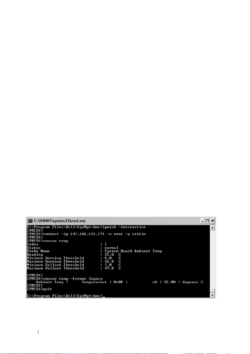
Description
This command displays the current status of platform sensors using one of
the two possible formats.
OPTIONS
[temp|fan|volt|discrete|numeric]
Specifies the sensor group (temp, volt, fan, discrete, or numeric) for which
information is displayed. If you do not specify a sensor group, all sensors for
which there is information will be displayed.
-format <oemlist|legacy>
Use different formats to output the sensor data. Default format is oemlist. Legacy
format is displayed as below:
Sensor Name | Sensor Type | Sensor # | Status [| Value
| Units ]
Subcommands
[temp | fan | volt | discrete | numeric]
Specifies the sensor group for which information is displayed. If no sensor
group is specified, information is displayed for all groups.
Figure 3-12. Sensor option example
72 Using the BMC Management Utility
Page 73

connect
Synopsis
connect -ip bmc-ip-address | bmc-host-name [-u
username] [-p password] [-k IPMI encryption key value]
connect -com bmc_ip_address | bmc_hostname -u username
-p password
[-k KG value]
Description
<command>
This command establishes an IPMI connection with the remote server in the
interactive mode to enable the user to perform server management activities.
The command remains active until the user quits the command prompt or
uses the command again to connect to a different server.
Options
-ip
bmc-ip-address|bmc_hostname
Specifies the out-of-band IP address or hostname of the remote managed
system.
-u
username
Specifies the username to connect to the remote system.
-p
password
Specifies the password to be used to connect to the remote managed system.
-k IPMI encryption key value
Specifies the KG value in Hex format. The IPMI encryption key is a public
key used to generate an encryption key for use between firmware and
application. It is differentiated from a password, which is not public and is
used to access the firmware. The maximum value is 20 ASCII hex pairs with
no spaces between the pairs.
NOTE: Even number of hexadecimal characters is valid and odd number of
hexadecimal characters is invalid. For example, 123456AB67 is valid, and 123 is
invalid. Enter 00, 0000, etc. to disable encryption.
Using the BMC Management Utility 73
Page 74

Figure 3-13. IPMISH connect option
LCD
Synopsis
lcd info
Description
This command displays the status of the LCD display on a x9xx or xx0x
system. You can also configure the LCD display using this command.
Subcommands
•
info
•
set
custom
none
•
•
default
— Displays information about the LCD display.
— Sets LCD display to either
none, default, custom
to set a string of your choice.
— Turns the LCD display off.
— Sets the default display on the LCD.
. Choose
Default Subcommand
If a subcommand is not specified, this command functions the same as lcd
info.
powermonitor
Synopsis
powermonitor status
Description
This command displays the current power status of the managed system.
74 Using the BMC Management Utility
Page 75

Subcommands
•
status
— Displays the current power status of the system.
The returned values denote energy consumption, peak power (in Watts),
and peak amperage.
clear peakpower
•
•
clear cumulativepower
Default Subcommand
— Deletes the peak power value.
— Deletes the cumulative power values.
If a subcommand is not specified, this command functions the same as power
status.
quit
Synopsis
quit
Description
This command exits the IPMI Shell interactive mode and returns to the
command mode.
help
Synopsis
help
[command]
Description
This command lists commands and capsule descriptions with syntax for each
command.
Argument
command
Specifies the command for which detailed description is required.
Using the BMC Management Utility 75
Page 76

Figure 3-14. IPMISH help option
SOL Proxy
SOL Proxy is a simple telnet server. It allows a telnet client to interact with
the hardware-designated serial port of a remote managed system using the
LAN communication channel. See Figure 3-15. With SOL Proxy,
administrators can view and change the BIOS settings over a shared LAN. In
addition, you can also access your managed system’s BMC using SOL Proxy
using the Linux serial console and Microsoft’s EMS/SAC interfaces. SOL
Proxy does not support in-band or serial connection to the managed system’s
BMC.
When BIOS console redirection to serial port is enabled on the remote
managed system, any application that uses the BIOS to read from or write to
the system console will have its I/O redirected to the designated serial I/O
port. When SOL is activated, the BMC firmware reads any data written to
the serial port and transmits it to the SOL Proxy as LAN packets. SOL Proxy
then forwards the data to the telnet client as TCP/IP packets.
Conversely, any keyboard activity at the telnet client is sent to the BMC by
SOL Proxy. BMC then writes the packets to the system serial I/O port.
NOTE: See your system’s User’s Guide for more information about console
redirection, including hardware and software requirements and instructions for
configuring host and client systems to use console redirection.
76 Using the BMC Management Utility
Page 77

The SOL Proxy communication scheme enables you to view and configure
the BIOS settings of a managed system, as well as to reset the managed
system remotely using a telnet client. SOL Proxy is installed as a daemon
service and automatically starts each time the system boots. SOL Proxy can
accommodate only one telnet session at a time.
You can use a variety of telnet clients to access SOL Proxy features. For
example:
• In a Windows environment, you can use a Command Prompt window as
your console. However, function keys such as <F1> and <F2> will not
operate correctly with this client except on systems running Windows
Server 2003.
• In a Windows environment, you can also use any telnet application that
supports VT100 or ANSI emulation mode (such as HyperTerminal) as your
console.
NOTICE: All versions of the Microsoft Windows operating system include
Hilgraeve's HyperTerminal terminal emulation software. However, the
included version does not provide many functions required during console
redirection. Instead, you can use any terminal emulation software that
supports VT100 or ANSI emulation mode. One example of a full VT100 or ANSI
terminal emulator that supports console redirection on your system is
Hilgraeve's HyperTerminal Private Edition 6.1 or later.
Using the BMC Management Utility 77
Page 78

NOTE: When using HyperTerminal, you must deselect the Wrap lines that
exceed terminal width check box to avoid console redirected data that may
→
appear to be corrupted or garbled. To deselect this feature, click File
→
Properties
width.
NOTE: See your system’s User’s Guide for more information about console
redirection, including hardware and software requirements and instructions for
configuring host and client systems to use console redirection.
Settings→ ASCII Setup…→ Wrap lines that exceed terminal
• In a Linux environment, you can use a shell such as
csh
or
ksh
as your
console, or you can use any telnet application supporting VT100 or ANSI
emulation mode.
NOTE: Telnet settings must be consistent with the settings on the managed system.
For example, the baud rates and terminal modes should match.
You can also send the terminal break function while in console redirection.
The use of this functionality requires that the specific terminal program in
use has the ability to send the break function. For example, you can send the
break signal through the Linux telnet modules by typing:
Ctrl+]send brk<Enter>
The Linux SysRq function is one example of an advanced debugging feature
that is enabled by use of the break function. See the "BIOS Configuration"
section on how to use this feature. See the "Serial Console redirection With
SOL Proxy" section for more information on the SysRq feature.
To enable BIOS console redirection for use with SOLProxy:
• Configure the
Redirection via COM2
available under the
• Configure the
PowerEdge
Redirection
option is available under the
Console redirection
for Dell
Serial Communication
Console Redirection
x8xx
systems. This option is available under the
menu in
BIOS Setup
attribute to
x9xx
and
xx0x
systems. This option is
submenu in BIOS setup.
attribute to
. Set
Serial Port 1
Integrated Devices
On with Console
Serial Port1
menu in
to
BMC NIC
BIOS Setup
for
Console
. This
.
Using SOL Proxy
Depending on the console you use, there are different steps for accessing SOL
Proxy. Throughout this section, the management station where the SOL
Proxy is running is referred to as the SOL Proxy Server.
78 Using the BMC Management Utility
Page 79

Initiating the SOL Proxy session using the Windows Command Prompt:
To connect and use SOL Proxy:
1
Open a Command Prompt window on your management station.
2
Enter the
telnet
command in the command-line and provide the
IP address of the SOL Proxy server and the port number that you specified
in the SOL Proxy installation (the default value is 623). For example:
telnet 192.168.1.24 623
NOTE: The IP address and port number you provide should conform to the
ones defined in the SOL Proxy configuration file. For more details, see
“Configuring the SOL Proxy Configuration File.”
3
If you are prompted for a username, provide the operating system login
credentials of the system running the service:
4
Provide a password when prompted. SOL Proxy will use this combination
DSM_BMU_SOL_Proxy
.
of operating system username and password to authenticate you on the
SOL Proxy Server. The specific authentication scheme will depend on the
operating system configuration for the SOL Proxy Server. However, if
localhost
or an IP address of 127.0.0.1 is used, it is assumed that the user
has login privileges to the current host, and is not prompted for a
username and password.
5
After authentication, a login successful message and the SOL Proxy main
menu prompt appear. You are ready to use SOL Proxy. By default, you will
be logged in the menu mode. See "SOL Proxy Main Menu" for further
instructions.
The following line edit functions are supported during the SOLProxy session:
1
Up- and down-arrow keys to browse command history.
2
Left- and right-arrow keys to move the input cursor.
Using the BMC Management Utility 79
Page 80

Using a Linux Shell
To connect and use SOL Proxy:
1
Open a Linux shell on your management station.
2
Enter the
telnet
command and provide the IP address of the SOL Proxy
Server and the port number you specified in SOL Proxy installation. For
example:
telnet 192.168.1.24 623
NOTE: The IP address and port number you provide should conform to the
ones defined in the SOL Proxy configuration file. For more details, see
“Configuring the SOL Proxy Configuration File.”
3
If you are prompted for a username, provide the operating system login
credentials of SOL Proxy Server.
4
Provide a password when prompted. SOL Proxy will use this combination
of operating system username and password to authenticate you on the
SOL Proxy Server. The specific authentication scheme will depend on the
operating system configuration for the SOL Proxy Server. However, if
localhost
or an IP address of 127.0.0.1 is used, it is assumed that the user
has login privileges to the current host, and is not prompted for a
username and password.
5
After authentication, a login successful message and the SOL Proxy main
menu prompt appear. You are ready to use SOL Proxy. See "SOL Proxy
Main Menu" for further instructions.
SOL Proxy Main Menu
After the telnet connection with SOL Proxy is successfully established, you
are presented with the following choices. See Figure 3-15.
80 Using the BMC Management Utility
Page 81

Figure 3-15. SOL Proxy Main Menu Example
The SOL Proxy main menu allows you to change the SOL settings of a
remote managed system’s BMC, reboot the remote BMC, or activate console
redirection.
When you select menu option 1, Connect to the Remote Server’s BMC, you
are prompted for the BMC IP address and BMC login. After you enter the
required information and make a successful connection, the internal state
SLP is changed to “connected.” If you select menu options 2, 3, or 4, and the
application state is not “connected,” you are prompted to connect to a BMC.
Menu option 2 allows you to enable, disable, and configure the SOL defaults,
including the minimum user privilege level required for activating SOL and
the communication baud-rate.
Menu options 3 and 4 allow you to establish a SOL remote console session
through the SOL Proxy main menu. Menu option 3 establishes a SOL session
without changing the remote system’s state. This option is ideal for connecting
to the Microsoft SAC/EMS or the Linux console. Menu option 4 reboots the
remote managed system and establishes a SOL session. This option is best
suited for performing BIOS setup and system configuration tasks.
Using the BMC Management Utility 81
Page 82

To exit an active SOL session, use the <~><.> character sequence.
This sequence terminates SOL and returns you to the top-level menu.
Connecting to the Remote Managed System’s BMC
NOTE: While multiple SOL sessions can be active at the same time, only one
console redirection session can be active at any given time for a managed system.
1
Select option 1 in the main menu.
2
Enter the BMC IP address of the remote managed system.
3
Provide the BMC username and password for the BMC on the managed
system. The BMC username and password must be assigned and stored in
the BMC non-volatile storage. See "Configuring Your Managed System"
for more information about configuring BMC users. Only one SOL session
with one BMC is permitted at one time.
The connection status displays on the main menu. See Figure 3-16.
4
Provide the IPMI encryption key if it was configured in the BMC.
Figure 3-16. Connecting to the Remote System’s BMC
82 Using the BMC Management Utility
Page 83

Configuring the SOL for the Remote Managed System
Select option 2 in the main menu.
NOTE: You must be connected to the managed system’s BMC before you can
configure the SOL features. If SOL Proxy is not yet connected to the managed
system’s BMC, you are prompted for an IP address, a username/password
combination, and an IPMI encryption key. The IPMI encryption key value will be
ignored if no key was set at the BMC on the target server. See "Connecting to the
Remote Managed System’s BMC" for more information.
The SOL configuration menu appears. According to the current SOL status,
the content of the SOL configuration menu varies:
• If SOL is already enabled, the current settings are displayed and you are
presented with three choices. See Figure 3-17.
Figure 3-17. Configuring the Serial-Over-LAN for the Remote System, Example 1
• If SOL is currently disabled, the options shown in Figure 3-18 are
Y
displayed. Type
to enable SOL or N to keep SOL disabled. See
Figure 3-18.
Using the BMC Management Utility 83
Page 84

Figure 3-18. Configuring the Serial-Over-LAN for the Remote System, Example 2
• If SOL is enabled, two BMC settings are displayed:
– The communication baud-rate between the system serial port and the
BMC
– The minimum BMC user privilege level required for activating
console redirection
SOL Proxy displays a list of valid values for each feature, as well as the
current value of the feature enclosed in a pair of brackets. Select the
number before a value to set it as the new setting, and press <Enter> to
confirm your changes. The new SOL settings are then displayed. See
Figure 3-19.
84 Using the BMC Management Utility
Page 85

Figure 3-19. SOL Settings, Example 3
Activating Console Redirection
Select option 3 in the main menu.
NOTE: You must be connected to the managed system’s BMC before you can
configure the SOL features. If SOL Proxy is not yet connected to the managed
system’s BMC, you are prompted for an IP address and a username/password
combination. See "Connecting to the Remote Managed System’s BMC" for more
information.
The remote managed system’s text console is redirected to your management
station. See Figure 3-20.
NOTE: BIOS Console Redirection must be enabled on the managed system and
correctly configured before SOL can be successfully activated. See "Configuring
Your Managed System" for more information.
Using the BMC Management Utility 85
Page 86

Figure 3-20. Console Redirection Example
Rebooting the Managed System and Activating Console Redirection
Select option 4 in the main menu.
NOTE: You must be connected to the managed system’s BMC before you can
configure the SOL features. If SOL Proxy is not yet connected to the managed
system’s BMC, you are prompted for an IP address, a username/password
combination, and an IPMI encryption key. The IPMI encryption key value will be
ignored if no key was set at the BMC on the target server. See "Connecting to the
Remote Managed System’s BMC" for more information.
The power state of the remote managed system is confirmed. If power is on,
you are prompted to decide between a graceful or forceful shutdown.
NOTE: This reboot feature mimics restarting the system using the server's power
button. A graceful shutdown of the server operating system may not be possible
when the server software stops responding, or if you are not logged as an
administrator at a local Windows console. In these cases, you must specify a
forced reboot instead of graceful reboot of Windows.
Next, the power state is monitored until the status changes to on. Console
redirection begins, and the remote managed system text console is redirected
to your management station. Use the escape character sequence <~><.>
to terminate console redirection and return to the top-level menu.
86 Using the BMC Management Utility
Page 87

While the managed system reboots, you can enter the BIOS system setup
program to view or configure BIOS settings. See Figure 3-21.
NOTE: Before activating the console redirection, you must first enable the console
redirection features. See "Configuring Your Managed System" for more information.
Figure 3-21. Reboot Example
Getting Help
Select option 5 in the main menu to display detailed descriptions for each
option. See Figure 3-22.
Using the BMC Management Utility 87
Page 88

Figure 3-22. Sample Help Screen
Exit
Select option 6 to end your telnet session and disconnect from SOL Proxy.
Using SOL proxy in command mode
By default, SOL Proxy is installed for use in the menu mode by the system. See
"Configuring the SOL Proxy Configuration File" section for instructions on
how to change the default settings to command mode.
Commands in SOL Proxy
SOL Proxy command mode is similar to the IPMI Shell interactive mode. In
addition to supporting all commands of the IPMI Shell interactive mode, the
SOL Proxy supports the following additional commands.
88 Using the BMC Management Utility
Page 89

console
Synopsis
console
Description
This command allows users to establish an SOL session with the connected
server.
NOTE: BMU responds with an error message if console is used before establishing
an IPMI session with connect.
reboot
Synopsis
reboot[-force]
Description
This command allows you to control power configurations and establish an
SOL session in one atomic operation. It is equivalent to executing the menu
command of "Reboot and Activate Console Redirection".
Options
-force
This option is used to force the system to shut down. If this option is omitted,
the "reboot" command is executed using a graceful shutdown.
Figure 3-23. reboot Option Example
Using the BMC Management Utility 89
Page 90

Configuring the SOL Proxy Configuration File
Certain parameters, for IPMI Shell and SOL Proxy, must be correctly
configured in the SOL Proxy Configuration file, - SOLProxy.cfg, which is
located in the default installation BMC directory.
The parameters and their descriptions are as follows:
Comments
Any line starting with a “#” is treated as a comment. For example:
#The file is an example.
IP Address
Specifies the specific IP address used to connect to SOL Proxy. This item
defines what kind of connection can be accepted to establish a SOL Proxy
telnet session. There are three possible values:
•
INADDR_ANY
•
127.0.0.1
•
IP address
For example:
ip=INADDR_ANY
Port Binding
Specifies the port at which the SOL Proxy listens for incoming connections.
By default, the port is set to 623 and can be modified by the user.
This item defines the port when you telnet SOL Proxy. If this item is absent,
623 is set as the default port. For example:
port=623
—
SOL proxy listens for input on any interface on the server.
— SOL proxy listens for input on the localhost only.
—
SOL proxy listens for input on this IP address only.
Session Timeout
Specifies the time in minutes before the SOL Proxy session times out.
If there is no keyboard activity for the specified timeout period, the telnet
session and the SOL session will be closed. The timeout value is specified in
minutes and can be changed during SOL Proxy installation. For example:
session_timeout=30
90 Using the BMC Management Utility
Page 91

Power-off Timeout
Specifies the time in seconds before the SOL Proxy gives up polling for the
managed system's power status. If the SOL Proxy issues the power off
command and the system does not power off within the specified interval, the
SOL Proxy returns with a message, indicating that the SOL Proxy was unable
to power off the system due to the timeout interval.
NOTE: When Reboot and Activate Console Redirection is selected and power for
the remote managed system is on, a power off IPMI command is issued. The power
status is then continually monitored until the power status reports “off.” If power
status remains “on” longer than this timeout period, Reboot and Activate Console
Redirection reports an error and returns to the top-level menu. This timeout value is
specified in seconds and can be changed during SOL Proxy installation.
For example:
power_off_timeout=60
Retry Interval
Specifies the period of time in seconds that the BMC waits before it tries to
resend a packet. The retry_interval unit is half a second. Therefore, a value of
2 means that the software waits one second for the BMC to respond before it
tries to resend the packet, a value of 4 means that it waits two seconds, and so
on. For example:
retry_interval=2
Retry Count
Specifies the maximum number of times that the software tries to resend a
packet if it does not receive a response from the BMC. Before each retry, the
software waits for the interval specified by the retry_interval parameter. For
example:
retry_count=10
User Interface
Specifies the default settings for SOL Proxy startup. The user can edit and set
this comment in the command or menu mode. For example:
user_interface=menu
Using the BMC Management Utility 91
Page 92

Sol Loss Silent
Specifies system behavior when one or more SOL packets are lost. The
possible values are 0 and 1. If it is set to 0 or is absent, the system will print an
error message on the screen each time an SOL packet is lost. If it is set to 1,
the system will not print error messages for loss of SOL packets. For example:
sol_loss_silent=0 or 1
Sol Loss Threshold
Specifies number of SOL packets that can be lost before SOL deactivation.
The default value is 0, which means that the system will deactivate SOL, if
any SOL packets are lost. For example,
sol_loss_silent_threshold=0
Sdr Cache
Specifies whether the system probe information is saved. This information
enhances speed of providing sensor and System Event Log (SEL) data. The
possible values are on and off. Default value is on. For example,
sdr_cache=on
Sdrcache Path
Specifies path where the system probe information is saved. Default location
is the installed BMC directory on your hard drive. For example,
sdrcache_path=<specified path directory>
Max Session
Specifies the maximum number of concurrent SOL sessions possible.
This default value is 1; any value less than 1 will be ignored or treated as 1.
You cannot set more than 20 sessions. For example,
max_session=2
Logpath
Specifies the path for storing the log files. Two log files, solproxy.log and
solproxyipmi.log, are created at the specified path. For example,
logpath=<specified location for log file>
92 Using the BMC Management Utility
Page 93

debug
Specifies if the debug data will be logged. The default is off.
debug=off
IPMItool
IPMItool is a CLI utility that helps in configuring and managing devices using the
IPMI version 1.5 and later protocol. IPMItool supports out-of-band (OOB) access
(over a LAN or through the serial port) to a single system at a time. However,
multiple IPMItool sessions can run simultaneously on the same managed system.
IPMItool allows a user with user-level BMC privileges to:
• Display the current power status.
• Display the 16-byte system GUID of the managed system.
• Display information from the system’s FRU.
• Display the BMC firmware information.
• Display summary information about the system event log.
• Display logged events.
• Display current status of platform sensors.
• Enable or disable SOL.
NOTE: See the IPMItool man page available on the World Wide Web for a
comprehensive list of features.
NOTE: While running ipmitool inband on Linux, if the OpenIPMI driver is not
running by default, it may cause commands to fail. To start the OpenIPMI drivers,
use the command
driver automatically during boot, use
service ipmi start. To set the system to start the
chkconfig ipmi on.
In addition to the operations that can be performed by a user with user-level
BMC user privileges, IPMItool allows a user with operator-level and
administrator-level BMC user privileges to:
• Power on, reset, or power cycle a managed system.
• Simulate a hard power off on a managed system (forcing the system to
turn off without shutting down the operating system).
• Clear the system event log (SEL).
• Turn the blinking system identification LED on or off.
Using the BMC Management Utility 93
Page 94

To facilitate command scripting, upon successful execution, IPMItool
terminates with an exit code of zero, and will output the execution results in
a parsable format. If an error is encountered, the program exits with a nonzero error code and outputs the error in a parsable format. See "BMC
Management Utility Error Codes" for a complete list of possible BMC
Management Utility error codes.
The complete list of commands listed under delloem in Table 3-2 are
supported by the IPMItool.
delloem
The delloem commands provide information on Dell-specific features.
Table 3-2 lists the delloem subcommands with a brief description.
Table 3-2. delloem Subcommands
Command Description
lcd
powermonitor
sysinfo
sel
sensor
Displays information on and helps configure the LCD
Dell
x9xx
and
xx0x
panel in
Displays information on and helps manage your
system’s power.
Displays information about your system.
Displays the system event log information.
Displays information on and helps manage your
system’s sensors
systems
.
Options for LCD
•
info
•
set [none|default|custom] <
to either none, default, or choose the
— Displays information about the LCD display.
string
custom
>
— Sets LCD display
option to set a string of your
choice.
Default Subcommand
If a subcommand is not specified, this command functions the same as lcd
info.
Options for powermonitor
94 Using the BMC Management Utility
Page 95

status—Displays the current power status of the system. The returned
values denote energy consumption, peak power (in Watts), and peak
amperage.
clear peakpower—Resets the peak power value.
clear cumulativepower—Resets the cumulative power values.
Default Subcommand
If a subcommand is not specified, this command functions the same as
powermonitor status.
Options for sysinfo
This command returns both FRU and BMC related information for your
system.
Options for sel
•
info
— Displays information about and the contents of the system
event log.
•
clear
•
list
<count>
•
— Deletes all records in the event log.
— Displays all contents of the event log.
|first
<count>
— Displays the first <
count
> (oldest)
entries in the SEL. If the count is zero, all entries are displayed.
•
last
<count>
— Displays the last <
count
> (most recent) entries in
the SEL. If the count is zero, all entries are displayed.
•
time
— Displays the most recent entries in the SEL. If the count is zero,
all entries are displayed. You can use the
system event log’s current time. The
get
command to display the
set <time string> option
allows you to set the system event log’s time. Future event log entries will
<
use the time set by this command.
MM/DD/YYYY HH:MM:SS
<
>.
time string> is in the form
NOTE: Hours are in 24-hour form. It is recommended that the event log be cleared
before setting the time.
NOTE: Time values between delloem sel time and sel time differ but
delloem sel time command returns the correct value for Dell systems.
the
Using the BMC Management Utility 95
Page 96

Default Subcommand
If a subcommand is not specified, this command functions the same as sel
info.
Options for sensor
•
list
— Displays the complete list of sensors and thresholds in a wide
table format.
get <id> ... [
•
<id>
]
— Displays information for sensors specified
by ID number.
•
thresh <id> <
threshold
> <
setting
>
— Allows you to set a
particular sensor threshold value. The sensor is specified by name. Valid
thresholds are:
•
unr
— Upper Non-Recoverable
•
ucr
— Upper Critical
unc
•
•
•
•
Default Subcommand
— Upper Non-Critical
lnc
— Lower Non-Critical
lcr
— Lower Critical
lnr
— Lower Non-Recoverable
If a subcommand is not specified, this command acts the same as sensor list.
IPMItool Command for Dynamic Entry on the DNS Server When DRAC is Not Present
To create a dynamic entry on the DNS server when DRAC is not present, use
the following command:
ipmitool raw 0x18 0x58 0xe4 0x15
NOTE: You must enter a 21-byte hexadecimal number (a 8-byte input for the
PowerEdge 1435SC) for the DHCP name. If the DHCP name is less than 21 bytes (8
bytes for PowerEdge SC1435), pad the end with zeroes.
96 Using the BMC Management Utility
Page 97

For example, to set the DNS server name to "foo":
ipmitool raw 0x18 0x58 0xe4 0x15 0x66 0x6f 0x6f 0x00
0x00 0x00 0x00 0x00 0x00 0x00 0x00 0x00 0x00 0x00 0x00
0x00 0x00 0x00 0x00 0x00 0x00
The ASCII character conversion chart is displayed in Table 3-3:
Table 3-3. ASCII Character Conversion Chart
Decimal Octal Hex Binary Value
000 000 000 00000000 NUL (Null character)
001 001 001 00000001 SOH (Start of Header)
002 002 002 00000010 STX (Start of Text)
003 003 003 00000011 ETX (End of Text)
004 004 004 00000100 EOT (End of Transmission)
005 005 005 00000101 ENQ (Enquiry)
006 006 006 00000110 ACK (Acknowledgment)
007 007 007 00000111 BEL (Bell)
008 010 008 00001000 BS (Backspace)
009 011 009 00001001 HT (Horizontal Tab)
010 012 00A 00001010 LF (Line Feed)
011 013 00B 00001011 VT (Vertical Tab)
012 014 00C 00001100 FF (Form Feed)
013 015 00D 00001101 CR (Carriage Return)
014 016 00E 00001110 SO (Shift Out)
015 017 00F 00001111 SI (Shift In)
016 020 010 00010000 DLE (Data Link Escape)
017 021 011 00010001 DC1 (XON) (Device Control 1)
018 022 012 00010010 DC2 (Device Control 2)
019 023 013 00010011 DC3 (XOFF) (Device Control 3)
020 024 014 00010100 DC4 (Device Control 4)
021 025 015 00010101 NAK (Negative Acknowledgement)
Using the BMC Management Utility 97
Page 98

Table 3-3. ASCII Character Conversion Chart (continued)
Decimal Octal Hex Binary Value
022 026 016 00010110 SYN (Synchronous Idle)
023 027 017 00010111 ETB (End of Transmission Block)
024 030 018 00011000 CAN (Cancel)
025 031 019 00011001 EM (End of Medium)
026 032 01A 00011010 SUB (Substitute)
027 033 01B 00011011 ESC (Escape)
028 034 01C 00011100 FS (File Separator)
029 035 01D 00011101 GS (Group Separator)
030 036 01E 00011110 RS (Request to Send) (Record Separator)
031 037 01F 00011111 US (Unit Separator)
032 040 020 00100000 SP (Space)
033 041 021 00100001 ! (Exclamation Mark)
034 042 022 00100010 " (Double Quote)
035 043 023 00100011 # (Number Sign)
036 044 024 00100100 $ (Dollar Sign)
037 045 025 00100101 % (Percent)
038 046 026 00100110 & (Ampersand)
039 047 027 00100111 ' (Single Quote)
040 050 028 00101000 ( (Left/Opening Parenthesis)
041 051 029 00101001 ) (Right/Closing Parenthesis)
042 052 02A 00101010 * (Asterisk)
043 053 02B 00101011 + (Plus)
044 054 02C 00101100 , (Comma)
045 055 02D 00101101 - (Minus or Dash)
046 056 02E 00101110 . (Dot)
047 057 02F 00101111 / (Forward Slash)
048 060 030 00110000 0
98 Using the BMC Management Utility
Page 99

Table 3-3. ASCII Character Conversion Chart (continued)
Decimal Octal Hex Binary Value
049 061 031 00110001 1
050 062 032 00110010 2
051 063 033 00110011 3
052 064 034 00110100 4
053 065 035 00110101 5
054 066 036 00110110 6
055 067 037 00110111 7
056 070 038 00111000 8
057 071 039 00111001 9
058 072 03A 00111010 : (Colon)
059 073 03B 00111011 ; (Semi-colon)
060 074 03C 00111100 < (Less Than)
061 075 03D 00111101 = (Equal Sign)
062 076 03E 00111110 > (Greater Than)
063 077 03F 00111111 ? (Question Mark)
064 100 040 01000000 @ (AT Symbol)
065 101 041 01000001 A
066 102 042 01000010 B
067 103 043 01000011 C
068 104 044 01000100 D
069 105 045 01000101 E
070 106 046 01000110 F
071 107 047 01000111 G
072 110 048 01001000 H
073 111 049 01001001 I
074 112 04A 01001010 J
075 113 04B 01001011 K
Using the BMC Management Utility 99
Page 100

Table 3-3. ASCII Character Conversion Chart (continued)
Decimal Octal Hex Binary Value
076 114 04C 01001100 L
077 115 04D 01001101 M
078 116 04E 01001110 N
079 117 04F 01001111 O
080 120 050 01010000 P
081 121 051 01010001 Q
082 122 052 01010010 R
083 123 053 01010011 S
084 124 054 01010100 T
085 125 055 01010101 U
086 126 056 01010110 V
087 127 057 01010111 W
088 130 058 01011000 X
089 131 059 01011001 Y
090 132 05A 01011010 Z
091 133 05B 01011011 [ (Left/Opening Bracket)
092 134 05C 01011100 \ (Back Slash)
093 135 05D 01011101 ] (Right/Closing Bracket)
094 136 05E 01011110 ^ (Caret/Circumflex)
095 137 05F 01011111 _ (Underscore)
096 140 060 01100000 `
097 141 061 01100001 a
098 142 062 01100010 b
099 143 063 01100011 c
100 144 064 01100100 d
101 145 065 01100101 e
102 146 066 01100110 f
100 Using the BMC Management Utility
 Loading...