


Dell OpenManage™
Baseboard Management
Controller Utilities
User’s Guide
www.dell.com | support.dell.com

Notes and Notices
NOTE: A NOTE indicates important information that helps you make better use of your computer.
NOTICE: A NOTICE indicates either potential damage to hardware or loss of data and tells you how to avoid the problem.
___________________
Information in this document is subject to change without notice.
© 2006 Dell Inc. All rights reserved.
Reproduction in any manner whatsoever without the written permission of Dell Inc. is strictly forbidden.
Trademarks used in this text: Dell, the DELL logo, OpenManage, and PowerEdge are trademarks of Dell Inc.; Microsoft, Windows, and Windows
Server are registered trademarks of Microsoft Corporation; Red Hat is a registered trademark of Red Hat Corporation; SUSE is a registered
trademark of Novell, Inc.; Intel is a registered trademark of Intel Corporation.
Other trademarks and trade names may be used in this document to refer to either the entities claiming the marks and names or their products.
Dell Inc. disclaims any proprietary interest in trademarks and trade names other than its own.
September 2006 Rev. A01

Contents
1 Introduction . . . . . . . . . . . . . . . . . . . . . . . . . . . . . . . . . 7
What’s New in BMC Management Utility 2.0. . . . . . . . . . . . . . . . . 8
Supported Systems
BMC Configuration and Management Tasks
Configuring the BMC
Managing the System Using BMC
BMC Action on Event
Basic BMC Alerting Over a LAN
IPMI Shell Over a LAN
IPMI Shell Over the Serial Cable
SOL Proxy Over a LAN
BMC Configuration and Management Tools
Using the Remote Access Configuration Utility
Using Deployment Toolkit
Using the BMC Management Utility
Using Server Administrator
Other Dell Documents You May Need
Obtaining Technical Assistance
. . . . . . . . . . . . . . . . . . . . . . . . . . . . . . . . . 8
. . . . . . . . . . . . . . . . . . . 9
. . . . . . . . . . . . . . . . . . . . . . . . . . . . . 9
. . . . . . . . . . . . . . . . . . . . . . 9
. . . . . . . . . . . . . . . . . . . . . . . . . . . . 11
. . . . . . . . . . . . . . . . . . . . . . 11
. . . . . . . . . . . . . . . . . . . . . . . . . . . 12
. . . . . . . . . . . . . . . . . . . . . . 13
. . . . . . . . . . . . . . . . . . . . . . . . . . . 14
. . . . . . . . . . . . . . . . . . . 15
. . . . . . . . . . . . . . 15
. . . . . . . . . . . . . . . . . . . . . . . . . . 15
. . . . . . . . . . . . . . . . . . . . 15
. . . . . . . . . . . . . . . . . . . . . . . . . 15
. . . . . . . . . . . . . . . . . . . . . . 16
. . . . . . . . . . . . . . . . . . . . . . . . . 17
2 Configuring Your Managed System . . . . . . . . . . . . . . . . . 19
BIOS Configuration. . . . . . . . . . . . . . . . . . . . . . . . . . . . . . . . 19
Configuring System BIOS in Dell PowerEdge™ x8xx Systems
Configuring System BIOS in Dell PowerEdge x9xx Systems
Using BIOS Console Redirection With SOL Proxy
. . . . . . . . . . . . . 22
. . . . . . . 19
. . . . . . . . 20
Baseboard Management Controller Configuration
Entering the Remote Access Configuration Utility
Remote Access Configuration Utility Options
. . . . . . . . . . . . . . . 23
. . . . . . . . . . . . . 23
. . . . . . . . . . . . . . . 23
Configuring Your BMC Using the Deployment Toolkit Utility
Installation and Setup for Microsoft Windows PE
Operating Systems
. . . . . . . . . . . . . . . . . . . . . . . . . . . . . 28
. . . . . . . . . . 28
Contents 3

Creating a CD . . . . . . . . . . . . . . . . . . . . . . . . . . . . . . . . 29
Installation and Setup for Linux Operating Systems
Basic configuration
. . . . . . . . . . . . . . . . . . . . . . . . . . . . . 30
. . . . . . . . . . . . 29
Configuring Your BMC Using Server Administrator
Using Dell Remote Access Controller 5
. . . . . . . . . . . . . . . 32
. . . . . . . . . . . . . . . . . . 33
3 Using the BMC Management Utility. . . . . . . . . . . . . . . . . 35
Installing the BMC Management Utility. . . . . . . . . . . . . . . . . . . . . 36
Installation Prerequisites
Supported Operating Systems
Installation Procedures
Installing on Systems Running Supported Windows
Operating Systems
Uninstalling on Systems Running Supported Windows
Operating Systems
Installing on Systems Running Supported Linux Enterprise
Operating Systems
Uninstalling on Systems Running Supported Linux Enterprise
Operating Systems
IPMI Shell
. . . . . . . . . . . . . . . . . . . . . . . . . . . . . . . . . . . . 39
Using IPMI Shell
IPMI Shell Command Syntax
IPMI Shell Global Options
IPMI Shell Commands
. . . . . . . . . . . . . . . . . . . . . . . . . . 36
. . . . . . . . . . . . . . . . . . . . . . . 36
. . . . . . . . . . . . . . . . . . . . . . . . . . . . . 37
. . . . . . . . . . . . . . . . . . . . . . . . . . . . . 37
. . . . . . . . . . . . . . . . . . . . . . . . . . . . . 38
. . . . . . . . . . . . . . . . . . . . . . . . . . . . . 38
. . . . . . . . . . . . . . . . . . . . . . . . . . . . . 39
. . . . . . . . . . . . . . . . . . . . . . . . . . . . . . 40
. . . . . . . . . . . . . . . . . . . . . . . . 41
. . . . . . . . . . . . . . . . . . . . . . . . . . 41
. . . . . . . . . . . . . . . . . . . . . . . . . . . 46
4 Contents
SOL Proxy
. . . . . . . . . . . . . . . . . . . . . . . . . . . . . . . . . . . . 56
Using SOL Proxy
Using SOL proxy in command mode
. . . . . . . . . . . . . . . . . . . . . . . . . . . . . . 58
. . . . . . . . . . . . . . . . . . . . 67
Configuring the SOL Proxy Configuration File
. . . . . . . . . . . . . . . . . . 68

4 Known Issues and Frequently Asked Questions . . . . . . . . 71
Known Issues . . . . . . . . . . . . . . . . . . . . . . . . . . . . . . . . . . 71
General Issues
SOL Proxy Issues
IPMI Shell Issues
. . . . . . . . . . . . . . . . . . . . . . . . . . . . . . . 71
. . . . . . . . . . . . . . . . . . . . . . . . . . . . . . 71
. . . . . . . . . . . . . . . . . . . . . . . . . . . . . . 71
Frequently Asked Questions
. . . . . . . . . . . . . . . . . . . . . . . . . . . 72
A BMC Management Utility Error Codes . . . . . . . . . . . . . . . 75
B Terminal Mode Commands
Configuring Terminal Mode . . . . . . . . . . . . . . . . . . . . . . . . . 79
Using Terminal Mode
Security Information
Syntax
. . . . . . . . . . . . . . . . . . . . . . . . . . . . . . . . . . . . . . 80
Command Length
Character Support
Hex-ASCII Command Format
Text Command Format
Examples
. . . . . . . . . . . . . . . . . . . . . . . . . . . . . . . . . . 82
. . . . . . . . . . . . . . . . . . . . . . . . . . . . 80
. . . . . . . . . . . . . . . . . . . . . . . . . . . . . . . 80
. . . . . . . . . . . . . . . . . . . . . . . . . . . . . . 80
. . . . . . . . . . . . . . . . . . . . . . . . . . . . . 81
. . . . . . . . . . . . . . . . . . . . . . . . . . . . . . 82
. . . . . . . . . . . . . . . . . . . . . . . 79
. . . . . . . . . . . . . . . . . . . . . . . . . . . 81
C Escape Key Sequences . . . . . . . . . . . . . . . . . . . . . . . . . 89
D Serial Port Console Redirection
. . . . . . . . . . . . . . . . . . . 91
Serial Communication . . . . . . . . . . . . . . . . . . . . . . . . . . . . . . 91
Console Redirection Via COM1
Console Redirection Via COM2
Serial Terminal Communication to BMC or DRAC
SPCR Table
. . . . . . . . . . . . . . . . . . . . . . . . . . . . . . . . . . . . 92
Serial Console redirection With SOL Proxy
Configuring Linux for Serial Redirection During Boot
Enabling Login to the Console After Boot
. . . . . . . . . . . . . . . . . . . . . . . 91
. . . . . . . . . . . . . . . . . . . . . . . 91
. . . . . . . . . . . . . 91
. . . . . . . . . . . . . . . . . . . 92
. . . . . . . . . . . 92
. . . . . . . . . . . . . . . . . 95
Contents 5

Glossary . . . . . . . . . . . . . . . . . . . . . . . . . . . . . . . . . . . . . . 99
. . . . . . . . . . . . . . . . . . . . . . . . . . . . . . . . . . . . . . . . 111
Index
6 Contents

Introduction
The Dell™ PowerEdge™ systems’ baseboard management controller (BMC) monitors the system for
critical events by communicating with various sensors on the system board and sends alerts and logs
events when certain parameters exceed their preset thresholds. The BMC supports the
industry-standard Intelligent Platform Management Interface (IPMI) specification, enabling you to
configure, monitor, and recover systems remotely. The BMC provides the following features:
• Access through the system’s serial port and integrated NIC
• Fault logging and SNMP alerting
• Access to the system event log (SEL) and sensor status
• Control of system functions including power on and power off
• Support that is independent of the system’s power or operating state
• Text console redirection for system setup, text-based utilities, and operating system consoles
• Access to Linux Enterprise server serial console interfaces by using Serial over LAN (SOL).
Dell provides several distinct utilities and programs for accessing the BMC to perform
management activities. The following BMC interfaces allow you to configure and manage your
system through the BMC:
• The BMC Management Utility allows remote, out-of-band LAN and/or serial port power control,
event log access, and console redirection.
• The Remote Access Configuration Utility enables configuring BMC in a pre-operating
system environment.
• The Dell OpenManage™ Deployment Toolkit Version 2.1 SYSCFG.EXE utility provides a
powerful command line configuration tool.
• Dell OpenManage Server Administrator allows remote, in-band access to event logs, power
control, and sensor status information and provides the ability to configure the BMC.
• Command Line Interface (CLI) tools provide a command line tool for sensor status information,
System Event Log (SEL) access, and power control.
Additionally, the BMC can be accessed by standard, off-the-shelf terminal or terminal emulator
utilities that allow access to sensor status information and power control.
Introduction 7

What’s New in BMC Management Utility 2.0
The BMC Management Utility (BMU) 2.0 has the following new features:
• Interactive mode for the IPMI Shell.
• New commands for IPMI Shell and SOL Proxy to connect to remote BMC and display sensor status.
• Choice of menu and command mode in SOL Proxy.
• Support for the following maximum baud rates for BMC serial communication and SOL:
– 19200 for PowerEdge 1425SC
– 57600 for PowerEdge
– 115200 for PowerEdge
• SOL activation through IPMI Shell interactive mode.
• Configuration of each SOL proxy server for up to 20 simultaneous SOL sessions.
• Support for SUSE
®
x9xx
Linux Enterprise Server.
and other PowerEdge
systems without Dell Remote Access Controller 5 (DRAC 5).
x9xx
systems with DRAC 5.
x8xx
systems.
Supported Systems
The BMC management features documented in this guide are supported on the following
Dell PowerEdge systems:
• 800
• 830
• 850
• 1425SC
• 1800
• 1850
• 1855
• 1900
• 1950
• 1955
• 2800
• 2850
• 2900
• 2950
• 6800
• 6850
8 Introduction

BMC Configuration and Management Tasks
The following sections document the basic tasks needed to set up and configure the BMC on a managed
system in preparation for using the BMC Management Utility. These basic tasks are:
• Configuring the BMC
• Managing the BMC
Configuring the BMC
To configure the BMC in a pre-boot environment, you can use the Remote Access Configuration Utility,
the Dell Remote Access Controller (DRAC) 5 Graphical User Interface (GUI), or the command line
interface (CLI) depending on the scope of your required configuration tasks. Alternately, you can
configure the BMC on a managed system with a running operating system using the Server
Administrator home page GUI or CLI. See "Baseboard Management Controller Configuration" for more
information.
Managing the System Using BMC
To manage the BMC in a pre-boot environment, or to access the BMC of a system, you can use the
BMC Management Utility. See "Using the BMC Management Utility." To configure the BMC on a
system with a running operating system or to perform everyday BMC management tasks, you can use the
GUI on the Server Administrator home page. See the Server Administrator User’s Guide for more
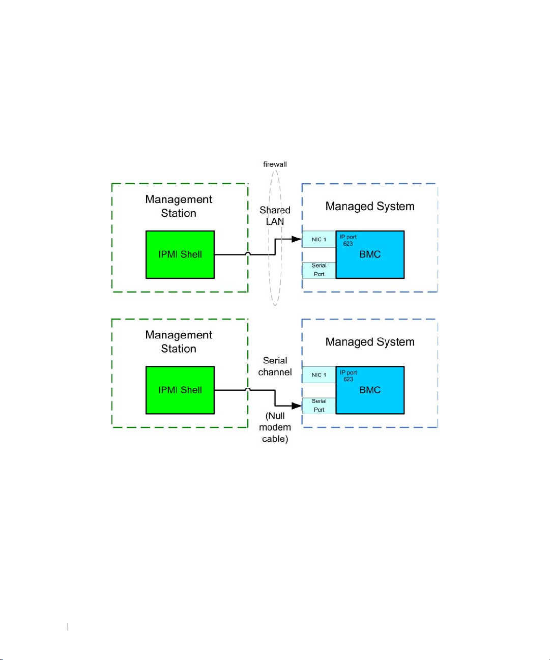
information about using Server Administrator to manage your system’s BMC functions. Figure 1-1 shows
the configuration matrix for BMC.
Introduction 9

Figure 1-1. BMC Configuration Matrix
10 Introduction

BMC Action on Event
If you plan to use your system’s BMC to peform actions when events occur, you must follow the BMC
Action on Event configuration guidelines listed in Table 1-1.
Table 1-1. BMC Action on Event Configuration Guidelines
Features Connection
Medium
• System Reset
• System Power Off
• System Power Cycle
LAN
BMC Configuration Tools Basic Configuration Tasks Management
To ol s
• Deployment Toolkit
(pre-operating system
environment)
• Server Administrator
• Enable platform events
• Enable alert actions
NA
Basic BMC Alerting Over a LAN
If you plan to use your system’s BMC to send alerts (Platform Event Traps), you must follow the
BMC configuration guidelines listed in Table 1-2.
NOTE: The LAN-sharing depends on the NIC selection configuration option. The available options are Shared and
Failover, and if a RAC card is present, the additional option available is Dedicated. See the NIC Selection option in the
table in "Remote Access Configuration Utility Options" section for more information on Shared, Failover, and Dedicated.
NOTE: The Dedicated NIC selection option is available only if you are using Dell Remote Access Controller (DRAC) 5.
Table 1-2. BMC LAN Alerting Configuration Guidelines
Features Connection
Medium
Platform Event
Alerts (SNMP
Tr a ps )
LAN
BMC Configuration Tools Basic Configuration Tasks Management
Tools
• Remote Access
Configuration Utility (preoperating system
environment)
• Deployment Toolkit (preoperating system
environment)
• Server Administrator
1
Configure NIC Selection to
select Shared, Failover, or
Dedicated
NOTE: This option is available
only on Dell PowerEdge x9xx
systems.
2
Configure the IP address,
Subnet mask, and Gateway
on the managed system
3
Configure the VLAN
(optional)
4
Enable alerting
5
Configure the Alert
destination IP address
6
Configure the Host Name
(optional)
IT Assistant
Introduction 11

IPMI Shell Over a LAN
Table 1-3 lists the actions you can perform, if you plan to use the BMC Management Utility’s IPMI Shell
or other IPMI tools to access your system’s BMC over a LAN.
Table 1-3. BMC LAN Access Configuration Guidelines
Features Connection
Medium
• Remote SEL
access
• Power control
•System
identification
•Sensor
information
LAN
BMC Configuration Tools Basic Configuration Tasks Management
Tools
• Remote Access
Configuration Utility (preoperating system
environment)
• Deployment Toolkit (preoperating system
environment)
• Server Administrator
1
Enable IPMI over LAN on
the managed system
2
Configure NIC selection to
select Shared, Failover, or
Dedicated
NOTE: This option is available
only on Dell PowerEdge x9xx
systems.
3
Configure the IP address,
Subnet mask, and Gateway
on the managed system
4
Configure IPMI encryption
key (optional)
IPMI Shell
NOTE: This option is available
only on Dell PowerEdge x9xx
systems.
5
Configure VLAN (optional)
6
Configure BMC users
12 Introduction

IPMI Shell Over the Serial Cable
If you plan to use the BMC Management Utility’s IPMI Shell to access your system’s BMC over a serial
cable, you must follow the BMC configuration guidelines listed in Table 1-4.
NOTE: Console redirection does not apply to BMC when using the serial interface.
Table 1-4. BMC Serial Configuration Guidelines
Features Connection
Medium
• Interactive
mode
• Remote SEL
access
• Power control
•System
identification
•System
information
• Access the
BMC of the
remote system
Accessed
through the
serial channel by
using a null
modem cable
BMC Configuration Tools Basic Configuration Tasks Management
Tools
• BIOS (pre-operating system
environment)
• Deployment Toolkit (preoperating system
environment)
• Server Administrator (to
enable BMC serial only)
1
Configure Serial Port 1 to
BMC Serial
NOTE: This option is available
only on Dell PowerEdge x8xx
systems.
2
Configure External Serial
Connector to Remote
Access
•IPMI Shell
(Basic
mode)
•Terminal
emulation
(Terminal
mode only)
NOTE: This option is available
only on Dell PowerEdge x9xx
systems.
3
Set Serial baud rate to
match the rate to be used by
the management tool
4
Set BMC Serial Connection
Mode to Basic for IPMI
Shell or Terminal for
Terminal emulation
5
Configure BMC users
Introduction 13

SOL Proxy Over a LAN
If you plan to use the BMC Management Utility’s SOL Proxy to access your system’s console over a LAN,
you must follow the BMC configuration guidelines listed in Table 1-5.
Table 1-5. BMC SOL Configuration Guidelines
Features Connection
Medium
• Text Utility
console
redirection
• Remote BIOS
setup
• Microsoft text
console
redirection
• Linux text
console
redirection
• Force a reboot
on a remote
system and
activate console
redirection
• Access BMC of
the remote
system
LAN
BMC Configuration Tools Basic Configuration Tasks Management
Tools
• BIOS (pre-operating system
environment)
• Remote Access
Configuration Utility (preoperating system
environment)
• Deployment Toolkit (preoperating system
environment)
• Server Administrator
1
Configure Serial Port 1 to
BMC NIC
NOTE: This option is available
only on Dell PowerEdge x8xx
systems.
2
Configure BIOS console
redirection to Serial Port 1
NOTE: This option is available
only on Dell PowerEdge x8xx
systems.
3
Configure Console
Redirection to On with
Console Redirection via
COM2
•SOL Proxy
•IPMI Shell
NOTE: This option is available
only on Dell PowerEdge x9xx
systems.
4
Configure other Console
Redirection parameters,
such as baud rate,
emulation type, etc.
5
Enable IPMI over LAN on
the managed system
6
Configure the IP address,
Subnet mask, and Gateway
on the managed system
7
Configure IPMI encryption
keyIPMI encryption key
(optional)
NOTE: This option is available
only on Dell PowerEdge x9xx
systems.
8
Configure VLAN (optional)
9
Configure BMC users
14 Introduction

BMC Configuration and Management Tools
Using the Remote Access Configuration Utility
The Remote Access Configuration Utility provides basic BMC setup and configuration functions that
can be accessed during system boot. Use the Remote Access Configuration Utility for initial BMC setup
and configuration only. For advanced configuration tasks, you must use the Deployment Toolkit
Version 2.1 SYSCFG.EXE utility or Server Administrator Version 2.0 or later.
NOTE: The Remote Access Configuration Utility is called the BMC Setup Module in the Dell PowerEdge x8xx systems.
Using Deployment Toolkit
The Deployment Toolkit Version 2.1 SYSCFG.EXE utility provides a powerful Microsoft Windows
Preinstallation Environment (PE) and Linux command-line interface for locally configuring your
system’s BMC as part of an initial deployment. Use the SYSCFG.EXE utility to set all supported BMC
features. Additionally, you can use the Deployment Toolkit utilities as part of a scripted deployment to
multiple similar systems. To use the SYSCFG.EXE utility, you must perform the following tasks:
• Download the Deployment Toolkit ISO image from the Dell Support website at
save the utilities to your hard drive.
• Burn the Deployment Toolkit ISO image containing the SYSCFG.EXE utility on a CD.
• Use the SYSCFG.EXE utility to configure BMC on the managed system.
See the Deployment Toolkit Version 2.1 User’s Guide and Command Line Interface Reference Guide for
more information about using the SYSCFG.EXE utility to configure and manage your system’s BMC.
support.dell.com
and
Using the BMC Management Utility
The BMC Management Utility provides a command-line interface to your remote management station
to manage BMC-supported functions. Use the BMC Management Utility to manage your BMC from a
remote management station and as your managed system’s emergency management console. The utility
gives you the option of using either a command line interface (IPMI Shell) or a SOL Proxy to access and
manage the BMC. To use the BMC Management Utility, you must perform the following tasks:
• Configure BMC using the Remote Access Configuration Utility, the Deployment Toolkit
SYSCFG.EXE utility, or Server Administrator.
• Install the BMC Management Utility on a management station.
See "Configuring Your Managed System" for instructions on configuring the BMC on a managed system
in preparation for using the BMC Management Utility.
Using Server Administrator
The Server Administrator provides a convenient and easy-to-use graphical user interface (GUI) for
remotely configuring or managing your system’s BMC on a system running a supported operating
system. You can use the Server Administrator to configure the most relevant BMC features, such as
Introduction 15

Platform Event Filter (PEF) parameters and alert destinations. Additionally, Server Administrator can be
used as a command line interface. Server Administrator requires that the system has an operating system
installed and functioning. As a result, Server Administrator is best suited for everyday BMC management
tasks, and is not an option for performing pre-boot setup or accessing the BMC as an emergency
management console. To use Server Administrator, you must perform the following tasks:
• Install Server Administrator on the managed system.
• Access the Server Administrator home page remotely or locally from a supported browser on a
management station.
• Configure BMC remotely or locally on the managed system.
See the Dell OpenManage™ Server Administrator Version 5.0 User’s Guide and Command line Interface
User’s Guide for more information about using Server Administrator to configure and manage your
system BMC.
Other Dell Documents You May Need
In addition to this User's Guide, you can find the following guides either on the Dell Support website at
support.dell.com or on the documentation CD:
• The
• The
• The
• The
• The
• The Dell system User’s Guide provides supplemental information about configuring your BIOS
Additionally, the Dell OpenManage readme.txt file provides the latest available information for the
installation and operation of the programs and utilities used to manage your system through the BMC.
The readme is available on the Dell OpenManage Systems Management Consoles CD and on the
Dell Support website at support.dell.com.
Dell OpenManage Quick Installation Guide
BMC Management Utility on a management station.
Dell OpenManage Server Administrator User’s Guide
Server Administrator to manage your system’s BMC.
Dell OpenManage Deployment Toolkit User’s Guide
installing and using the Deployment Toolkit utilities.
Dell OpenManage Deployment Toolkit Command Line Interface Reference Guide
complete list of all valid BMC-related command-line options, suboptions, and arguments.
Dell OpenManage IT Assistant User’s Guide
manage a large number of client and server systems on a local area network (LAN) or wide area
network (WAN).
settings with the System Setup Program, as well as instructions for configuring your system to use
console redirection.
provides additional information about installing the
provides additional information about using
provides additional information about
provides a
provides information about how to monitor and
16 Introduction

Obtaining Technical Assistance
If at any time you do not understand a procedure described in this guide or if your product does not
perform as expected, help tools are available to assist you. For more information about these help tools,
see "Getting Help" in your system's Installation and Troubleshooting Guide or the Hardware Owner’s
Manual.
Additionally, Dell Enterprise Training and Certification is available; see www.dell.com/training for more
information. This service may not be offered in all locations.
Introduction 17

18 Introduction

Configuring Your Managed System
Before using the BMC Management Utility, configure certain items, such as the necessary system
BIOS, network, Intelligent Platform Management Interface (IPMI) encryption key, and serial
connection settings, depending on the functionality to be performed, to enable access to the BMC.
NOTE: The IPMI encryption key is a public key that is used to generate an encryption key for use between the
firmware and the application.
In addition, to utilize the BMC Management Utility IPMI serial functions, you must have a working
connection between the management station and the correct serial I/O port of the target BMC,
using a null modem cable.
This section describes the basic procedures you must perform to prepare your BMC to be accessed
and managed using the BMC Management Utility. The following procedures are described:
• BIOS Configuration
• Baseboard Management Controller Configuration
• Configuring Your BMC with the Deployment ToolKit SYSCFG.EXE utility
• Configuring Your BMC with Dell™ OpenManage™ Server Administrator
BIOS Configuration
For most configurations, you must configure the serial port settings and the console redirection
settings in your system BIOS before you can use the BMC Management Utility. To configure the
necessary system BIOS setting, your must enter the System Setup Program. The BIOS settings can
also be configured using the Deployment Toolkit or the
Server Administrator.
NOTE: For more information about configuring BIOS settings, see your system User’s Guide.
Configuring System BIOS in Dell PowerEdge™ x8xx Systems
1
Turn on or restart your system.
2
Press <F2> immediately after you see the following message:
<F2> = Setup
The
System Setup
NOTE: If your operating system begins to load before you press <F2>, allow the system to finish booting,
and then restart your system and try again.
3
Use the up- and down-arrow keys to navigate to the
screen appears.
Integrated Devices
Configuring Your Managed System 19
field and press <Enter>.

4
Use the up- and down-arrow keys to navigate to the
5
Use the space bar to select the serial port option.
The options are
COM1, COM3, BMC Serial, BMC NIC, Off
installed in the system).
Serial Port 1
field and press <Enter>.
, and
RAC
(if an optional RAC is
To use BMC, serial port 1 uses the
or the integrated shared NIC. RAC control uses only the
COM1
address and communication can be through the serial port
COM1
available options when Console Redirection is set to use serial port 1.
a
Select
b
Select
BMC Serial
BMC NIC
if you are planning to access the BMC through the serial cable connection.
if you are using SOL proxy and are planning to access the BMC over a
shared LAN.
6
Press <Enter> to return to the
7
Use the up- and down-arrow keys to navigate to the
8
Use the up- and down-arrow keys to navigate to the
space bar to set the console redirection feature to
System Setup
screen.
Console Redirection
Console Redirection
Serial Port 1
Redirection after Boot.
9
Use the up- and down- arrow keys to navigate to the
Failsafe Baud Rate
bar to set the console failsafe baud rate, if applicable.
10
Use the up- and down-arrow keys to navigate to the
space bar to select either
11
Press <Enter> to return to the
12
Press <Esc> to exit the System Setup program. The
•
Save Changes and Exit
•
Discard Changes and Exit
•
Return to Setup
13
Choose the appropriate option and exit the system setup.
VT 100/VT 200
System Setup
or
ANSI, if applicable.
Remote Terminal Type
screen.
Exit
screen displays the following options:
address.
Off
and
COM3
are not
field and press <Enter>.
option and then use the
. Optionally, you can also enable
option and then use the space
option and then use the
Configuring System BIOS in Dell PowerEdge x9xx Systems
1
Turn on and restart your system.
2
Press <F2> immediately after you see the following message:
<F2> = Setup
The
System Setup
NOTE: If your operating system begins to load before you press <F2>, allow the system to finish booting, and
then restart your system and try again.
3
Use the up- and down- arrow keys to navigate to the
4
Use the spacebar to select the appropriate serial communication option.
20 Configuring Your Managed System
screen appears.
Serial Communication
field and press <Enter>.

5
Select the appropriate option for Console Redirection. The following options are available:
On without Console Redirection:
COM1 and COM2 are enabled and available for use by the
operating system or applications. Console redirection is disabled. This is the default option.
On with Console Redirection via COM1:
When BIOS console redirection is enabled through COM1,
the COM1 port is not available to applications through the operating system.
On with Console Redirection via COM2:
When BIOS console redirection is enabled through COM2,
the COM2 port is not available to applications through the operating system.
Off:
COM1 and COM2 are both disabled and not available for use by the operating system or
applications. BIOS Console redirection is disabled.
NOTE: Select On with Console Redirection via COM2 to use Console Redirection with SOL.
6
Press <Enter> to select and return to the previous screen.
7
Use the up- and down- arrow keys to navigate to the
External Serial Communication
field and
press <Enter>.
8
Use the spacebar to select the appropriate external serial communication option.
The available options are
NOTE: Select Remote Access to access the BMC through the serial cable connection. This option can be set
to any value for using SOL and accessing the BMC over LAN.
9
Press <Enter> to select and return to the previous screen.
10
If required, use the spacebar to navigate to and change the settings for
11
Use the up- and down- arrow keys to navigate to the
COM1, COM2
, and
Remote Access.
The default option is
Failsafe Baud Rate
COM1
Redirection after Boot.
option and then use the space
bar to set the console failsafe baud rate, if applicable.
12
Use the up- and down- arrow keys navigate to the Remote Terminal Type option and then use the
space bar to select either
13
Press <Enter> to return to the
14
Press <Esc> to exit the System Setup program. The
•
Save Changes and Exit
•
Discard Changes and Exit
•
Return to Setup
VT 100/VT 200
System Setup
or
ANSI,
if applicable.
screen.
Exit
screen displays the following options:
.
NOTE: For most options, any changes that you make are recorded but do not take effect until you restart the system.
NOTE: Press <F1> to display the help file for the System Setup program.
Configuring Your Managed System 21

Using BIOS Console Redirection With SOL Proxy
Console redirection allows maintenance of a system from a remote location by redirecting keyboard
input and output through the serial port. Any console-based feature or operating system can then be
used to access the server. DR-DOS, Linux (init 3) and Windows
are examples of operating systems and consoles that can be used to access the server.
By default, some operating systems, such as Windows Server
send text console output to the BIOS. Manual configuration of the Redirection after Boot feature
through the system BIOS may not be visible to the operating system. This results in both, the operating
system feature and the BIOS redirection feature, being enabled. Depending on the operating system and
its setup, the results may vary. Dell recommends the following steps as good practice:
DR-DOS: Do not configure DR-DOS for serial console output. Enable console redirection after reboot
in system BIOS.
Windows Special Administrative Console (SAC): Do not configure Windows SAC for serial console
redirection. Enable console redirection after reboot in system BIOS.
Linux: Do not configure console redirection after rebooting the system BIOS. Do the tasks listed in the
"Installation and Setup for Linux Operating Systems" section, to configure Linux for console redirection.
NOTE: See" Escape Key Sequences" for a list of keystrokes to be used for BIOS Setup operations from a serial
terminal.
®
Special Administrative Console (SAC)
™
2003, are automatically configured to
22 Configuring Your Managed System

Baseboard Management Controller Configuration
You can perform basic BMC configuration using the Remote Access Configuration Utility during system
startup. See Figure 2-1. For more advanced configuration options, see the instructions for the
SYSCFG.EXE utility in the Deployment Toolkit 2.1 User’s Guide.
Figure 2-1. Remote Access Configuration Utility
Entering the Remote Access Configuration Utility
1
Turn on or restart your system.
2
Press <
If your operating system begins to load before you press <
booting, and then restart your system and try again.
Ctrl-E
> when prompted after POST.
Crtl-E
>, allow the system to finish
Remote Access Configuration Utility Options
Table 2-1 lists the Remote Access Configuration Utility options and shows how to configure the BMC on
a managed system. After entering all settings, press <Esc> and select one of the following:
•
Save Changes and Exit
•
Discard Changes and Exit
•
Return to Setup
- Keep all entries made in the Remote Access Configuration Utility.
- Undo all entries made in the Remote Access Configuration Utility.
-
Continue using the Remote Access Configuration Utility.
Configuring Your Managed System 23

Table 2-1. Remote Access Configuration Utility
Option Description
IPMI Over LAN Enables or disables the out-of-band LAN channel access to the shared
network controller.
NIC Selection
NOTE: This option is available only
on Dell PowerEdge x9xx systems.
Displays the configuration option.
•Shared
Select this option to share the network interface with the host
operating system. The remote access device network interface is fully
functional when the host operating system is configured for
NIC teaming.
The remote access device receives data through NIC 1 and NIC 2,
but transmits data only through NIC 1.
NOTE: If NIC 1 fails, the remote access device will not be accessible.
NOTE: The NIC 2 is not available on the PowerEdge 1900 system.
• Failover
Select this option to share the network interface with the host
operating system. The remote access device network interface is fully
functional when the host operating system is configured for
NIC teaming.
The remote access device receives data through NIC 1 and NIC 2,
but transmits data only through NIC 1. If NIC 1 fails, the remote
access device fails over to NIC 2 for all data transmission.
The remote access device continues to use NIC 2 for data
transmission. If NIC 2 fails, the remote access device fails over all
data transmission back to NIC 1.
NOTE: This option cannot be selected on the PowerEdge 1900 system.
•Dedicated
Select this option to enable the remote access device to utilize the
dedicated network interface available on the Remote Access
Controller (RAC). This interface is not shared with the host
operating system and routes the management traffic to a separate
physical network, enabling it to be separated from the application
traffic.
NOTE: This option is available only on systems with a DRAC installed.
LAN Parameters
RMCP+ Encryption Key
NOTE: This option is available only on PowerEdge x9xx systems.
The Key is used to encrypt the IPMI sessions. The encryption key is
entered as a maximum of 20 pairs of ASCII hexadecimal characters
representing 20 bytes; for example,
01FA3BA6C812855DA001FA3BA6C812855DA0A0A0.
24 Configuring Your Managed System

Table 2-1. Remote Access Configuration Utility (continued)
Option Description
IP Address Source Displays whether the network controller will be assigned a
DHCP
address.
Ethernet IP Address
IP address or a
The static IP address of the BMC. This field is limited to a maximum
value of 255.255.255.255.
The following IPv4 rules apply:
• IP addresses cannot be
• The first octet must be between
127.xxx.xxx.xxx
1-223
(i.e.
, where
xxx
is between
143.xxx.xxx.xxx
NOTE: IP address 169.254.0.2 subnet mask 255.255.0.0 is returned when
the BMC is unable to contact the DHCP server.
MAC Address This field is read-only.
Displays the network controller’s BMC MAC address.
Subnet Mask The subnet mask for the static IP address.
NOTE: IP address 169.254.0.2 subnet mask 255.255.0.0 is returned when
the BMC is unable to contact the DHCP server.
Default Gateway The IP gateway for the static IP address.
VLAN Enable Enables or disables the virtual LAN ID.
VLAN ID This field is read-only when
VLAN Enable
is set to
off
To enter a value, navigate to the VLAN ID field from another field.
A valid value for the virtual LAN ID must be a number from 1 to 4094.
NOTE: If you enter a value outside the specified range, either 1 or 4094
is entered, whichever is closest.
VLAN This field is read-only when
Specifies the priority of the VLAN. The valid values range from
Priority 0 - Priority 7
LAN Alert Enabled Enables or disables LAN alerting.
Alert Policy Entry 1 Enables or disables the first alert destination.
Alert Destination 1 This field is read-only when
Enter the IP address of the first alert destination. Use the Left or Right
arrow keys to navigate to each octet. Use the numeric keypad to enter
each octet.
The following IPv4 rules apply:
• IP addresses cannot be
• The first octet must be between
• The last octet must not be
(i.e.
xxx.xxx.xxx.0
VLAN Enable
.
LAN Alert Enabled
127.xxx.xxx.xxx
1-223
(i.e.
0
or
255
or
xxx.xxx.xxx.255
is set to
off
is set to
, where
xxx
is between
143.xxx.xxx.xxx
)
Static
.
.
)
off
)
0-255
.
0-255
.
.
Configuring Your Managed System 25

Table 2-1. Remote Access Configuration Utility (continued)
Option Description
Host Name String Specifies the managed system hostname used to correlate Platform
Event Traps to the system on which they originate.
Use alpha-numerics, but no symbols (except ’-’) or spaces.
Advanced LAN Parameters
NOTE: This option is available only on systems with a DRAC installed.
Dedicated NIC Configuration Options
NIC
Auto-Negotiate
LAN Speed Setting
Enables or disables the NIC
Enables or disables Auto-Negotiation of the LAN Speed.
This field is read-only when Auto-Negotiate is set to Enabled.
Set the LAN Speed Setting to 10 or 100 Mbps
LAN Duplex Setting
This field is read-only when Auto-Negotiate is set to Enabled.
Sets the LAN communication method to Half or Full Duplex.
DNS Configuration Options
DNS Servers from DHCP
on = IP addresses of the DNS Servers are assigned by the DHCP
off = IP addresses of the DNS Servers are set manually
DNS Server 1
This field is read-only when DNS Servers from DHCP is set to
on.
Enter the IP Address of DNS Server 1
The following IPv4 rules apply:
DNS Server 2
• IP addresses cannot be
• The first octet must be between
• The last octet must not be
xxx.xxx.xxx.0
(i.e.
This field is read-only when DNS Servers from DHCP is set to
127.xxx.xxx.xxx
1-223
(i.e.
0
or
255
or
xxx.xxx.xxx.255
, where
xxx
is between
143.xxx.xxx.xxx
)
0-255
)
on.
Enter the IP Address of DNS Server 2
The following IPv4 rules apply:
Register RAC Name
Register RAC Name
• IP addresses cannot be
• The first octet must be between
• The last octet must not be
xxx.xxx.xxx.0
(i.e.
on = You may enter the Current DNS RAC Name.
This field is read-only when Register RAC Name is set to off.
127.xxx.xxx.xxx
1-223
(i.e.
0
or
255
or
xxx.xxx.xxx.255
, where
xxx
is between
143.xxx.xxx.xxx
)
0-255
)
Enter the Current DNS RAC Name using 1-32 alpha-numerics,
spaces, and symbols. Press <Enter> to save the value. Press <Esc>
to exit the field without saving.
.
.
26 Configuring Your Managed System

Table 2-1. Remote Access Configuration Utility (continued)
Option Description
Domain Name from DHCP
Domain Name
Virtual Media Configuration
Virtual Media
Virtual Flash
LAN User Configuration Enables setting the user name, user password, user privilege, and
Account Access Enables or disables account privileges.
Account Priviledge Sets the account to one of:
Account User Name Sets the account user name.
Enter Password Enter the password for this Account User. You must enter at least one
Confirm Password Confirm the password you entered.
Reset To Default Clears the BMC settings and resets the BMC setting to the defaults.
Turns the domain name on or off.
This field is read-only when DNS Servers from DHCP is set to
on.
Enter the Domain Name using 1-64 alpha-numerics, spaces, and
symbols. Press <Enter> to save the value. Press <Esc> to exit the
field without saving.
NOTE: This option is available only on systems with a DRAC installed.
Attaches or detaches a virtual media drive.
Enables or disables virtual flash memory.
enables user access for user ID=2.
Admin, User, Operator, No Access
non-null acharacter.
NOTICE: Resetting to factory defaults will restore remote non-
volatile settings.
System Event Log Menu Enables viewing and clearing the System Event Log (SEL). A popup box
will indicate that the SEL is being read.
Total System Event Log Entries Displays the number of records in the SEL.
View System Event Log Displays a record in the SEL, starting with the most recent record. Enter
a record number to view, using the
Right and Left arrow keys to scroll up and down the SEL.
Clear System Event Log Erases all records in the SEL.
NOTE: If the first integrated network interface controller (NIC 1) is used in an Ether Channel team or link
aggregation team, the BMC management traffic will not function on PowerEdge x8xx systems. The NIC teaming
option is supported only on PowerEdge x9xx systems. For more information about network teaming, see the
documentation for the network interface controller.
Advance to Entry
Configuring Your Managed System 27
field. Use the

Configuring Your BMC Using the Deployment Toolkit Utility
The Dell OpenManage Deployment Toolkit Version 2.1 SYSCFG.EXE Utility includes a set of
Microsoft
The Deployment ToolKit (DTK) SYSCFG.EXE utility is specifically designed to address all necessary
BMC configuration tasks using a powerful and comprehensive command-line interface. This utility runs
on PowerEdge 1425SC and all supported PowerEdge x7xx, x8xx, and x9xx systems.
To use the BMC Management Utility, configure your managed system with the SYSCFG.EXE utility by
performing the following tasks:
• Install the Deployment Toolkit Version 2.1.
• Create either a BMC configuration diskette or CD containing a bootable image, the appropriate CD
• Configure BMC Users.
• Configure BMC SOL access.
• Configure BMC IPMI serial access.
®
Windows PE and Linux-based utilities for configuring and deploying PowerEdge systems.
drivers (for a CD only), and the SYSCFG.EXE utility.
Installation and Setup for Microsoft Windows PE Operating Systems
NOTE: See the Deployment Toolkit Version 2.1 User’s Guide for additional information about installing and using the
utilities, and the Deployment Toolkit Version 2.1 Command Line Interface Reference Guide for a complete list of
valid options, suboptions, and arguments for using the SYSCFG.EXE to configure and manage your BMC.
The Deployment Toolkit components are provided as a self-extracting zip file on the Dell Support
website at support.dell.com. The self-extracting file can be opened on any system running a Microsoft
Windows operating system, or it can be extracted at the Windows Command Prompt (cmd.exe) using
the PKUNZIP.EXE utility (not supplied with the Deployment Toolkit). By default, the dtk-2.
AXX.exe files are extracted to the root directory of your local hard drive, for example, C:\. This location
can be changed by giving a different path when extracting the file. Perform the following steps to extract
the Deployment Toolkit components to a workstation running Windows:
1
Download the Deployment Toolkit file
support.dell.com
2
After the zip file downloads, double-click the file.
3
Click OK.
4
Click
Unzip
By default, the Deployment Toolkit files are unzipped to
the
C:\Dell\Toolkit\Tools
and save it anywhere on a system running a supported Windows operating system.
.
directory.
dtk-2.X-winpe-AXX.exe
C:
\. The
from the Dell Support website at
SYSCFG.EXE
utility is located in
X
-dos-
28 Configuring Your Managed System

Creating a CD
Use the following steps to create bootable media that can be used to configure the BMC on a
managed system:
1
Create a directory,
2
Insert the Windows OEM Preinstallation Kit (OPK) CD into your CD drive.
3
Copy all CD files from the Windows PE directory to the
4
Copy
factory.exe
WinPE_OPKTools
5
Remove the CD from the CD drive.
6
Create and name a directory on your development system hard drive. This is where the ISO file
is stored.
7
Navigate to the
8
Run the following command:
OSCDIMG -bETFSBOOT.COM -n <DELLWINPEBUILD>
ETFSBOOT.COM is part of the OPK tools and makes the Windows PE CD bootable. The following
command line creates a bootable ISO image called Dellx86winpe.iso:
C:\WINPE_OPKTOOLS\OSCDIMG -bETFSBOOT.com -n c:\DELLWINPEBUILD
C:\FINALBUILD\Dellx86winpe.iso
Copy the SYSCFG.EXE utility to the root of the directory.
9
10
Start your CD burning software and generate a bootable CD using the bootable diskette you created as
the boot image.
You are now ready to use your bootable CD to configure the BMC on a managed system. For more
information, see "Configuring the BMC."
WinPE_OPKTools
and
netcfg.exe
from the
directory.
WinPE_OPKTools
, on your hard drive.
WinPE_OPKTools
CD drive
\tools\x86 directory to the
directory through a command prompt.
directory.
Installation and Setup for Linux Operating Systems
NOTE: See the Deployment Toolkit Version 2.1 User’s Guide for additional information about installing and using the
utilities, and the Deployment Toolkit Version 2.1 Command Line Interface Reference Guide for a complete list of all
valid options, suboptions, and arguments for using the SYSCFG.EXE to configure and manage your BMC.
1
Obtain the ISO image of embedded Linux available on the Dell Support website at
2
Burn the ISO image using any commonly available CD burning software.
NOTE: When you create a bootable CD, this image is supplied to the CD burning software along with the complete
deployment directory structure, which includes all necessary supporting files to perform the deployment.
3
The CD burning software creates an image of the self-bootable ISO image and the deployment files
on the CD.
4
Extract the contents of the ISO image to a folder on your hard drive.
Configuring Your Managed System 29
support.dell.com
.

5
Copy your custom scripts into the folder you created in step 4.
NOTE: Your scripts should also take care of copying miscellaneous items to unlock the CD, so that the CD can
be mounted and ejected as required by the operating system’s installation process.
6
In
/mnt/cdrom/isolinux.cfg
NOTE: The scripts that you copy into the CD will be copied to and run from the RAM disk. This task is done to
ensure the CD is not locked. Ensure that your sample scripts have valid path names.
7
Copy the directory structure created in your work station, into the root folder that you created in "step 4".
8
This folder contains the Deployment Toolkit CD files necessary for operating system installation, and
, the cd install section points to your customized start-up script.
files required for replication.
9
Use the
isolinux
utility to burn the contents of the folder you created in "step 7" to a CD and make
it bootable.
10
Your ISO image is ready for booting.
Basic configuration
Before you can use the BMC Management Utility to remotely manage the BMC on a managed system,
you must perform some basic configuration tasks. The Deployment Toolkit SYSCFG.EXE utility
provides a powerful command-line interface for performing the following configuration tasks:
• Configuring BMC users for the managed system
• Configuring the BMC IP address for IPMI LAN access and SOL access for the managed system
• Configuring the BMC serial channel for IPMI serial access for the managed system
NOTE: See the Deployment Toolkit Version 2.1 User’s Guide for additional information about installing and using the
Deployment Toolkit utilities, and the Command Line Interface Reference Guide for a complete list of valid options,
suboptions, and arguments for using the SYSCFG.EXE to configure and manage your BMC.
Configuring New BMC Users
The BMC is configured by default with user ID 2 set to username: root and password: calvin. It is
highly recommended that you change the user name and password when deploying your system.
1
Insert the bootable BMC configuration diskette or CD into the appropriate drive of the system to be
deployed and reboot the system.
2
To create a new user, at the command prompt, type:
syscfg username --userid=X --name=
where X is a number between 2–10 and
name
name
is an ASCII string of 16 or fewer characters.
Press <Enter> to execute the command line options.
3
To enable the new user ID, at the command prompt, type:
syscfg useraction --userid=X --action=enable
Press <Enter> to execute the command line options.
30 Configuring Your Managed System

4
To set the password for a BMC user, at the command prompt, type:
syscfg passwordaction --action=setpassword --userid=X --password=
where
password
characters for PowerEdge
NOTICE: A password must be set for each BMC user. The BMC firmware does not allow access to users with
null user names or passwords.
is an ASCII string of 16 or fewer characters for PowerEdge
x9xx
systems.
x8xx
systems and 20
password
Press <Enter> to execute the command-line options.
5
To configure BMC user privilege, at the command prompt, type:
syscfg lanuseraccess --usrprivlmt=bmcuserprivilege where
bmcuserprivilege=
user, operator, administrator, noaccess
Press <Enter> to execute the command-line options.
Configuring the BMC IP Address
1
Insert the Deployment Toolkit CD into the appropriate drive of the system to be deployed and reboot
the system.
2
To configure the BMC IP address source for the LAN channel to DHCP, at the command prompt,
type:
syscfg lcp --ipaddrsrc=dhcp
Press <Enter> to execute the command line options.
For a complete list of valid options, suboptions, and arguments for configuring the BMC LAN channel
see the
Deployment Toolkit Version 2.1 Command Line Interface Reference Guide
.
3
To configure the BMC IP address source for the LAN channel to a static IP address, at the command
prompt, type:
syscfg lcp --ipaddrsrc=static --ipaddress=
--subnetmask=
XXX.XXX.XXX.X
--gateway=
XXX.XXX.XXX.XX
XXX.XXX.XXX
.X
Press <Enter> to execute the command line options.
For a complete list of valid options, suboptions, and arguments for configuring the BMC LAN channel
see the
Configuring the BMC Serial Channel Access
1
Insert the bootable diskette or CD into the appropriate drive of the system to be deployed, and reboot
Deployment Toolkit Version 2.1 Command Line Interface Reference Guide
.
the system.
Configuring Your Managed System 31

2
To configure the serial port for BMC, at the command prompt, type:
syscfg scp --connectionmode=basic --msgcommbitrate=
where
XXXXX
Press <Enter> to execute the command line options.
3
To configure the terminal mode for BMC, at the command prompt, type:
syscfg scp --connectionmode=terminal --msgcommbitrate=
where
XXXXX
Press <Enter> to execute the command line options.
For a complete list of valid options, suboptions, and arguments for configuring the BMC serial
channel, see the
is the baud rate in bps.
is the baud rate in bps.
Deployment Toolkit Version 2.1 Command Line Interface Reference Guide
XXXXX
XXXXX
.
Configuring Your BMC Using Server Administrator
You can also configure the BMC options using Server Administrator Version 5.0, which is a one-to-one
systems management software program that must be installed on the managed system. Once installed,
you can remotely access Server Administrator from a management station with a supported browser to
perform BMC configuration tasks. See the Server Administrator User’s Guide for more information about
installing and using Server Administrator.
You can configure the BMC settings from either the Server Administrator home page or from its
command line interface. Users must have Administrator privileges to access the BMC settings. Users
logged in with User or Power User group privileges can view the BMC information but cannot change
the settings.
See the Server Administrator Version 5.0 Command Line Interface User's Guide for information about
configuring the BMC from the command line.
When using Server Administrator, you can click Help on the global navigation bar for more detailed
information about the specific window you are viewing. Server Administrator help is available for all
windows accessible to the user based on user privilege level and the specific hardware and software
groups that Server Administrator discovers on the managed system.
The Server Administrator Instrumentation Service allows you to manage BMC features, such as, general
BMC information, configuration of the LAN and serial port, BMC users, and BIOS setup. To use Server
Administrator to configure the BMC on a managed system, perform the following steps:
NOTE: You must be logged in with Admin privileges to configure the BMC settings.
1
Log in to the Server Administrator home page for the target system.
2
Click the
3
Click the
4
Click the
32 Configuring Your Managed System
System
object.
Main System Chassis
Remote Access
object.
object.

5
The
BMC Information
6
Click the
Under the
7
Click the
Under the
NOTICE: A password must be set for each BMC user. The BMC firmware does not allow access to users with null
user names or passwords.
Configuring BIOS in Server Administrator
Configuration
Configuration
Users
tab.
Users
window is displayed.
tab.
tab, you can configure LAN, Serial Port, and Serial Over LAN.
tab, you can modify the BMC user configuration.
To configure BIOS in Server Administrator, complete the following steps:
1
Click the
2
Click the
3
Click the
4
Click the
In the
System
object.
Main System Chassis
BIOS
object.
Setup
tab.
Setup
tab, you can configure
object.
Console Redirection
and
Serial Port communication
parameters.
Using Dell Remote Access Controller 5
The Dell Remote Access Controller (DRAC) 5 provides a Web-based interface and RACADM (a
command-line interface) that enables you to configure the DRAC 5 properties and users, perform
remote management tasks, and troubleshoot a remote (managed) system for problems.
Configuring the Network and IPMI LAN Settings
NOTE: You must have Configure DRAC 5 permission to do the following steps.
NOTE: Most DHCP servers require a server to store a client identifier token in its reservations table. The client
(DRAC 5, for example) must provide this token during DHCP negotiation. For RACs, the DRAC 5 supplies the client
identifier option using a one-byte interface number (0) followed by a six-byte MAC address.
NOTE: If your managed system DRAC is configured in Shared or Shared with Failover mode and the DRAC is
connected to a switch with Spanning Tree Protocol (STP) enabled, network clients will experience a 20 to 30
second delay in connectivity when the management station’s LOM link state changes during the STP convergence.
1
Access the DRAC 5 Web-based interface. See the
Dell Remote Access Controller 5 User’s Guide
more information.
2
Click
Remote Access
3
Click the
4
Configure the DRAC 5 NIC settings in the
Configuration
Network Settings and IPMI Settings on the
in the
System
tab and then click
tree.
Network
.
Network Configuration
Network Configuration
Configuring Your Managed System 33
page. Table 2-1 describes the
page.
for

5
Click
Apply Changes
6
Click the appropriate
Adding and Configuring DRAC 5 Users
when completed.
Network Configuration
page button to continue.
Create unique users with specific administrative permissions (or role-based authority) to manage your
system with the DRAC 5 and maintain system security. For additional security, you can also configure
alerts that are e-mailed to specific users when a specific system event occurs.
NOTE: You must have Configure DRAC 5 permission to do the following steps.
1
Expand the System tree and click
2
Click the
Configuration
tab and then click
Remote Access
Users
.
. The
Users
page appears, which includes each user’s
State, RAC Privilege, IPMI LAN Privilege, and IPMI Serial Privilege.
3
Click a user ID number in the User ID column.
4
Configure the user’s properties and privileges in the
5
Click
Apply Changes
6
Click the appropriate
See the
Dell Remote Access Controller 5 User’s Guide
when completed.
User Configuration
page button to continue.
User Configuration
page.
for more information on the IPMI user privileges,
DRAC group permissions, and the DRAC user privilege settings.
34 Configuring Your Managed System

Using the BMC Management Utility
The BMC Management Utility is a collection of software applications that enable remote
management and configuration of systems equipped with a BMC. The BMC Management Utility
includes the following components:
• Command Line Interface (IPMI Shell)
The IPMI Shell is a scriptable console application program used for the control and management
of remote systems using the IPMI 1.5 protocol or later. The IPMI Shell supports both serial access
and LAN access to the BMC . It can be used either in the generic CLI mode or the interactive
mode. The interactive mode allows for a dedicated connection to a server and availability of all
commands from the operating system CLI. Using the IPMI Shell in this mode improves usability
and reduces time and traffic required for connecting and authenticating.
The IPMI Shell allows administration of one or more managed systems from a command line shell,
rather than a graphical user interface (GUI). Use the IPMI Shell to perform the following tasks:
– System power management
– System identifier control
– Access to the event log
– Access to the system sensors
– Enable Serial-over-LAN for a remote managed system
• Serial-Over-LAN Proxy (SOL Proxy)
The SOL Proxy is a telnet daemon that allows LAN-based administration of remote systems using
the Serial Over LAN (SOL) and IPMI protocols. Any standard telnet client application, such as
HyperTerminal on Microsoft
features. SOL can be used either in the menu mode or command mode. The SOL protocol
coupled with the remote system's BIOS console redirection allows administrators to remotely view
and change a managed system’s BIOS settings over a LAN. The Linux serial console and
Microsoft's EMS/SAC interfaces can also be accessed over a LAN using SOL.
®
Windows® or telnet on Linux, can be used to access the daemon's
NOTICE: All versions of the Microsoft Windows operating system include Hilgraeve's HyperTerminal terminal
emulation software. However, the included version does not provide many functions required during console
redirection. Instead, you can use any terminal emulation software that supports VT100 or ANSI emulation
mode. One example of a full VT100 or ANSI terminal emulator that supports console redirection on your system
is Hilgraeve's HyperTerminal Private Edition 6.1 or later.
NOTE: See your system’s User’s Guide for more information about console redirection, including
hardware and software requirements and instructions for configuring host and client systems to use
console redirection.
Using the BMC Management Utility 35

NOTE: HyperTerminal and telnet settings must be consistent with the settings on the managed system. For
example, the baud rates and terminal modes should match.
NOTE: The Windows "telnet" command that is run from a MS-DOS
the BIOS needs to be set for ANSI emulation to display all the screens correctly.
®
prompt supports ANSI terminal emulation, and
Installing the BMC Management Utility
The BMC Management Utility is installed on a management station to remotely connect to the
managed system’s BMC. See Figure 3-1.
Installation Prerequisites
Before using the BMC Management Utility, you must perform at least the basic BIOS and
BMC configuration tasks described in "Configuring Your Managed System."
In addition, to access the BMC using the IPMI serial feature, you must have a working connection
between the management station and the correct serial I/O port of the managed system’s BMC using a
null modem cable.
Figure 3-1. Installing on a Management Station
Supported Operating Systems
The management station must be running one of the following supported operating systems:
• Red Hat Enterprise Linux AS, ES, WS (version 3.0) 32-bit and 64-bit
• Red Hat Enterprise Linux AS, ES, WS (version 4.0) 32-bit and 64-bit
• Microsoft Windows 2000 and Microsoft Windows XP
• Microsoft Windows Server™ 2003 Web, Standard, and Enterprise Editions
®
•SUSE
36 Using the BMC Management Utility
Linux Enterprise Server

Installation Procedures
The following installation procedures provide step-by-step instructions for installing and uninstalling the
BMC Management Utility for each supported operating system:
• Installing/uninstalling on systems running supported Windows operating systems
• Installing/uninstalling on systems running supported Linux operating systems
Installing on Systems Running Supported Windows Operating Systems
To install the BMC Management Utility on a management station running the Windows operating
system, perform the following steps:
1
Log in with administrator privileges to the system where you want to install the systems management
software components.
2
Exit any open application programs and disable any virus-scanning software.
3
Insert the
If the CD does not automatically start the setup program, click the
type
The
4
Click
The
5
Click
A software license agreement appears.
Dell OpenManage™ Systems Management Consoles
x:\windows\setup.exe
Dell OpenManage Management Station Installation
Install, Modify, Repair or Remove Management Station
Welcome to Install Wizard for Dell OpenManage Management Station
Next
.
(where x is the drive letter of your CD drive).
CD into your system's CD drive.
Start
button, click
screen appears.
.
Run
, and then
screen appears.
6
Select
I accept the terms in the license agreement,
Setup Type
The
7
Select
Custom Setup
Custom Setup
The
8
From the drop-down menu, which appears on the left side of BMC Console, select
all subfeatures will be installed on the local hard drive
To accept the default directory path, click
where you want to install your software, and then click
Ready to Install the Program
The
9
Ensure that all information is correct and click
Installing Dell OpenManage Management Station
The
the installation.
10
When installation is complete, the
NOTE: Enable the virus scanning software after installation.
screen appears.
and click
screen appears.
Next
.
Next
screen appears.
Install Wizard Completed
if you agree.
.
. Otherwise, click
Next
.
Install
.
screen appears and displays the status of
screen appears. Click
Using the BMC Management Utility 37
Browse
and navigate to the directory
This feature, and
Finish
.

See the Dell OpenManage Version 5.0 User's Guide for additional information about installing the
BMC Management Utility on a management station.
By default, the installation program copies the files to the following directory:
C:\Program Files\Dell\SysMgt\bmc.
The SOL Proxy service does not auto-start after installation. To start the SOL Proxy service after
installation, you can reboot the system (SOL Proxy automatically starts on a reboot). To restart the
SOL Proxy service on Windows systems, complete the following steps:
1
Right-click
2
Click
3
Locate
My Computer
Services and Applications
DSM_BMU_SOLProxy
and click
Manage.
and then click
in the list of services and right-click to start the service.
The
Computer Management
Services.
Available services are displayed to the right.
window is displayed.
Uninstalling on Systems Running Supported Windows Operating Systems
To uninstall the BMC Management Utility, use the Add/Remove Programs utility in the Control Panel.
Installing on Systems Running Supported Linux Enterprise Operating Systems
To install the BMC Management Utility on a management station running the Linux operating system:
1
Log in as root to the system where you want to install the management station components.
2
If required, mount the
mount /mnt/cdrom
3
Install the BMC Management Utility with the following command for SUSE Linux Enterprise server:
rpm -ivh /linux/bmc/osabmcutil9g-SUSE*.rpm
or for Red Hat Enterprise Linux, use the following command:
rpm -ivh /linux/bmc/osabmcutil9g-RHEL*.rpm
By default, the installation program copies the files to the following locations:
/etc/init.d/SOLPROXY.cfg
/etc/SOLPROXY.cfg
/usr/sbin/dsm_bmu_solproxy32d
/usr/sbin/solconfig
/usr/sbin/ipmish
The SOL Proxy will start automatically during system startup. Alternatively, you can go to directory
/etc/init.d
solproxy status
dsm_bmu_solproxy32d start
dsm_bmu_solproxy32d stop
solproxy restart
and use the following commands to manage the SOL Proxy service:
Systems Management Consoles
CD using the command:
38 Using the BMC Management Utility

Uninstalling on Systems Running Supported Linux Enterprise Operating Systems
To uninstall the BMC Management Utility, perform the following steps:
Log in as
1
2
Enter either of the following command to remove all the installed packages from SUSE Linux
Enterprise Server or Red Hat Enterprise Linux.
rpm -e osabmcutil9g-SUSE*
rpm -e osabmcutil9g-RHEL*
If the BMC Management Utility has been uninstalled, you will receive a success message.
root
.
IPMI Shell
IPMI Shell is a CLI console application and has no GUI. Its commands and options are specified using
command line arguments only.
IPMI Shell supports out-of-band (OOB) access (over a LAN or through the serial port) to a single system
at a time, however, multiple IPMI Shell sessions can run simultaneously on the same managed system.
See Figure 3-2.
IPMI Shell allows a user with user-level BMC privileges to:
• Display the current power status.
• Display the 16-byte system GUID of the managed system.
• Display information from the system’s field replaceable unit (FRU).
• Display the BMC firmware information.
• Display summary information about the event log.
• Display logged events.
• Display current status of platform sensors
• Enable or disable SOL.
In addition to the operations that can be performed by a user with user-level BMC user privileges, IPMI
Shell allows a user with operator-level and administrator-level BMC user privileges to:
• Power on, reset, or power cycle a managed system.
• Simulate a hard power off on a managed system (forcing the system to turn off without shutting down
the operating system).
• Clear the system event log (SEL).
• Turn the blinking system identification LED on or off.
Using the BMC Management Utility 39
To facilitate command scripting, upon successful execution, IPMI Shell terminates with an exit code of
zero, and will output the execution results in a parsable format. If an error is encountered, the program
exits with a non-zero error code and outputs the error in a parsable format. See "BMC Management
Utility Error Codes" for a complete list of possible BMC Management Utility error codes.
Figure 3-2. IPMI Shell Diagram
Using IPMI Shell
To use IPMI Shell, perform the following steps:
On systems running a supported Microsoft Windows operating system:
1
Start a
Command Prompt
2
Locate the
Files\Dell\SysMgt\bmc.
3
Enter IPMI Shell commands (see "IPMI Shell Command Syntax") to manage the remote system. See
"IPMI Shell Commands" for a complete list of valid options, commands, subcommands,
and arguments.
40 Using the BMC Management Utility
ipmish.exe
window.
file. By default,
ipmish.exe
is located in the directory:
C:\Program

On systems running a supported Linux operating system:
1
Start an operating system (OS) shell.
2
Enter IPMI Shell commands (see "IPMI Shell Command Syntax") to manage the remote system. See
"IPMI Shell Commands" for a complete list of valid options, commands, subcommands,
and arguments.
NOTE: The IPMI Shell will be located in /usr/sbin.
IPMI Shell Command Syntax
The general syntax of IPMI Shell CLI commands is as follows:
ipmish [
The general usage for a command is:
command [subcommand
Both global options and command-specific options are always in the following form:
option argument
-
For example:
-help
-max 20
-u John
Arguments with embedded tabs or spaces must be enclosed in matching double quotation marks (").
For example:
-user "John Smith"
global-options
] [
] …
command [; command
] …
command option and argument
] …
Every command has one default action. The default action is typically, but not always, the equivalent of
reading and displaying the current setting or status for the command.
IPMI Shell Global Options
IPMI Shell has the following global options:
Running IPMISH over LAN Option -ip
Synopsis
ipmish -ip
[-k KG value]
bmc_ip_address
<command>
|
bmc_hostname
-u
username
Using the BMC Management Utility 41
-p
password

Description
This option is used to establish a connection to a remote managed system using the LAN channel. The
IP port specified in installation (default value is 623) is used unless another port has been configured.
NOTE: This global option cannot be used independently to connect to the BMC. One or more IPMISH commands
must follow the option.
Options
-ip
bmc_ip_address
|
bmc_hostname
Specifies the IP address or hostname of the remote managed system.
-u
username
Specifies the BMC username.
-p
password
Specifies the BMC user password.
-k
KG value
Specifies the KG value in Hex format. The IPMI encryption key is a public key used to generate an
encryption key for use between firmware and application. It is differentiated from a password, which is
not public and is used to access the firmware. The maximum value is 20 ASCII hex pairs with no spaces
between the pairs.
NOTE: Even number of hexadecimal characters is valid and odd number of hexadecimal characters is invalid. For
example, 123456AB67 is valid, and 123 is invalid. Enter 00, 0000, etc. to disable encryption.
NOTE: The IPMI encryption key is available only on PowerEdge
Running IPMISH over Serial - Option -com
Synopsis
ipmish -com
username
-u
serial_port
-p
password
-baud
baud_rate
™
x9xx systems.
-flow
flow_control
The following attributes should be configured for IPMISH over serial to function correctly.
NOTE: These options can be configured in BIOS Setup, as well as using Dell OpenManage tools. Log on to Server
Administrator and navigate to BIOS Setup.
• "External Serial Connector" must be configured and set to "Remote Access" for PowerEdge
systems. This option is available in the "Serial Communication" submenu in BIOS setup.
• Disable the "RAC serial Console" if you have a DRAC 5 card installed. Log on to the DRAC GUI,
navigate to Serial and deselect the "Enable Serial console" checkbox.
• Set "Serial port 1" to "BMC Serial" for PowerEdge
x8xx
systems. This option is available under the
Integrated Devices menu in BIOS Setup.
42 Using the BMC Management Utility
x9xx

The Serial communication connection mode for the BMC must be set to "Direct Connect Basic Mode"
for all systems. This can be configured using Server Administrator. Log on to Server Administrator and
navigate to Serial Port.
Description
This option establishes a connection to a remote managed system using the serial channel.
NOTE: This global option cannot be used independently to connect to the BMC. One or more IPMISH commands
must follow the option.
Options
-com
serial_port
Specifies the serial port used when establishing an IPMI session to the managed system. For a system
running Windows, the management station port can be 1, 2, 3, and so on. For systems running Linux,
the management station port can be ttyS0, ttyS1, ttyS2, and so on.
-baud
baud_rate
Specifies the communication baud rate over the serial channel. The maximum reliably supported baud
rates are:
• 19200 for PowerEdge
• 57600 for PowerEdge
• 115200 for PowerEdge
NOTE: The baud rate for serial channel should match the baud rate set in the managed system.
-flow
flow_control
x8xx
systems
x9xx
systems without Dell Remote Access Controller 5 (DRAC 5)
x9xx
systems with DRAC 5
Specifies the data flow control method. There are two flow control options: CTS (hardware flow control)
and NONE (no flow control).
-u
username
Specifies the BMC username.
password
-p
Specifies the BMC user password.
IPMI Help Option -help
Synopsis
ipmish -help [
command
]
Using the BMC Management Utility 43
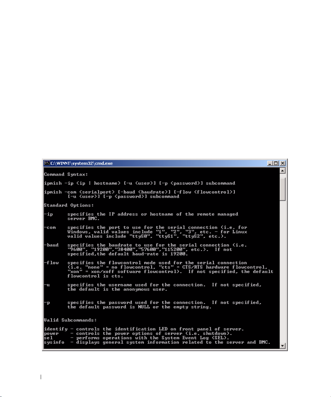
Description
This option displays the following information:
• A summary page for all commands
• A summary of all subcommands for a single command
• A detailed description of a command-subcommand combination
Options
-help
subcommand
A command list and a capsule description of options are printed if no argument is given. When there is
an argument specifying a valid command, the help option displays a detailed description of the
command. See Figure 3-3 and Figure 3-4.
Figure 3-3. IPMI Help Option Example 1
44 Using the BMC Management Utility
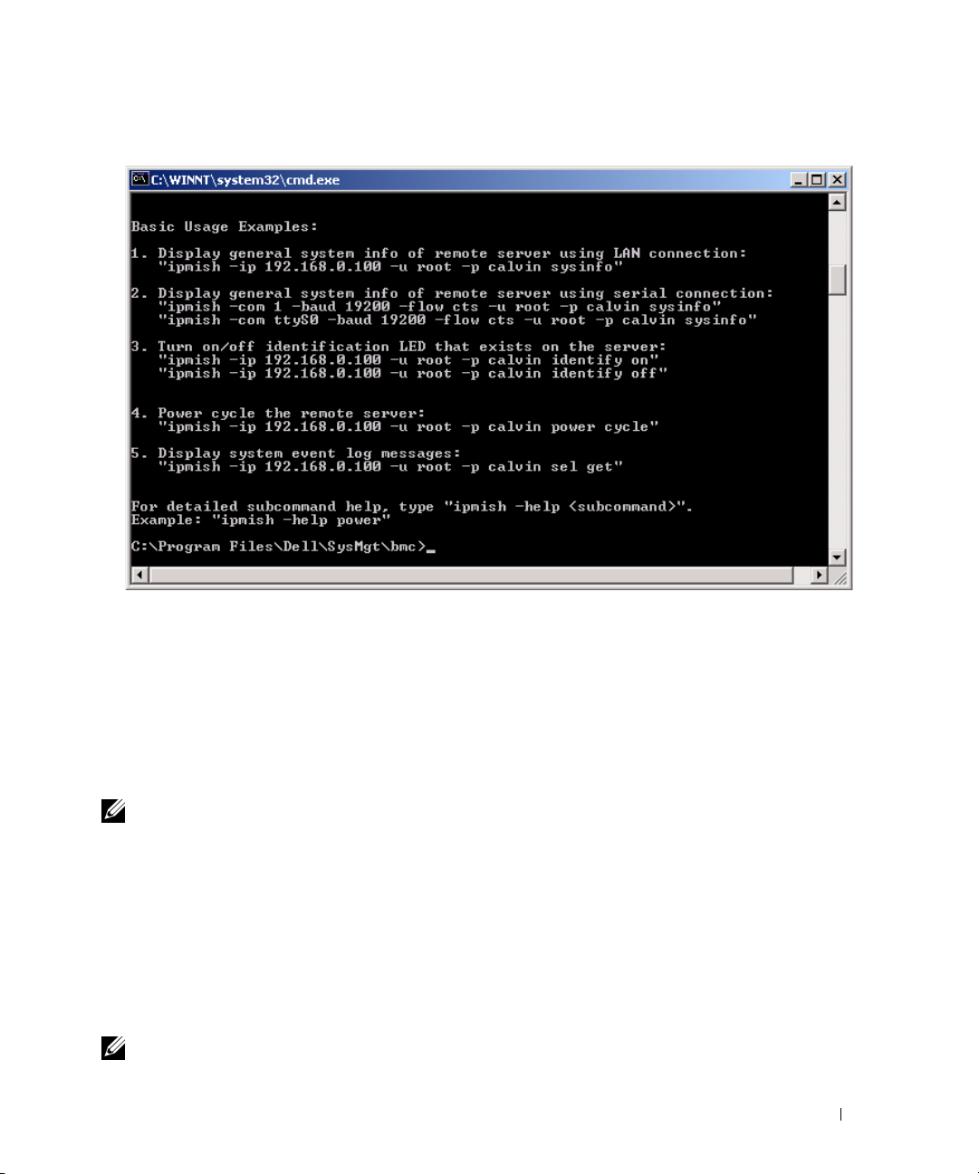
Figure 3-4. IPMISH Help option Example 2
IPMI Session Option -interactive
Synopsis
ipmish -interactive [-cfg
<config-file>
]
Description
This option invokes the interactive CLI mode. An IPMISH prompt appears when entering interactive
CLI mode. Type quit to exit the IPMISH prompt and return to the CLI prompt.
NOTE: The command prompt responds with an error message in the interactive mode, if a command is used
before establishing an IPMI session with connect.
Options
-interactive
Invokes the interactive CLI mode.
<config-file>
-cfg
Specifies the configuration file for BMU to start the CLI mode with. If a configuration file is not
specified, BMU operates with default configuration settings.
NOTE: The -interactive option must be followed by connect for ipmish to work.
Using the BMC Management Utility 45

See "Configuring the SOL Proxy Configuration File" for more information on configuration files.
Figure 3-5. IPMISH interactive option
The following line edit functions are supported during the interactive session:
1
Up and Down arrow keys to browse command history.
2
Left and Right arrow keys to move the input cursor.
3
Home and End keys to move the input cursor to the beginning or end of the line.
4
Backspace key to move the input cursor back by one space.
The following line edit functions are supported for the SOL proxy menu mode:
Left and Right arrow key to move the input cursor.
1
2
Home and End keys to move the input cursor to the beginning or end of the line.
3
Backspace key to move the input cursor back by one space.
IPMI Shell Commands
Table 3-1 lists IPMI Shell commands with a brief description.
NOTE: The sol, sensor, and connect commands can be used in the IPMI Shell interactive and non-interactive
modes and the quit command can be used only in the interactive mode.
Table 3-1. IPMI Shell Commands
Command Description
identify Controls the identification LED on the front panel.
sysinfo Retrieves and displays managed system information.
power Controls the power state of the managed system.
46 Using the BMC Management Utility

Table 3-1. IPMI Shell Commands (continued)
Command Description
sel Displays or deletes information from the SEL.
sol Enables Serial-over-LAN for the remote managed system.
sensor Displays current status of platform sensors.
connect Connects to the BMC of the remote managed system.
help displays a command list with descriptions and syntax of options.
quit exits the command prompt.
identify
Synopsis
identify [on [-t
Description
seconds
] | off]
This command controls the identification LED on the front panel. See Figure 3-6.
Subcommands
on
off
Turns the managed system’s front panel LED on or off. If the BMC supports the IPMI extension Chassis
Identify On command, then the identify on command turns the LED on indefinitely until the identify
off command is used to turn the LED off.
NOTE: Acknowledgement or status check of the command is not displayed on the command prompt. You should
manually check the status on the system.
Options
-t
seconds
Specifies how long the LED is on. It should be no longer than 255 seconds.
Default Subcommand
If a subcommand is not specified, this command acts the same as the identify on command.
Using the BMC Management Utility 47

Figure 3-6. identify Option Example
sysinfo
Synopsis
sysinfo [fru | id]
Description
This command retrieves and displays the system information, including field replaceable unit (FRU) and
BMC information for the managed system. See Figure 3-7 and Figure 3-8.
Subcommands
fru — Returns FRU related information
id — Returns BMC related information
Default Subcommand
If a subcommand is not specified, this command acts the same as sysinfo id. See Figure 3-7.
Figure 3-7. sysinfo Option Example
48 Using the BMC Management Utility

Figure 3-8. sysinfo FRU Example
power
Synopsis
power status
power off [-force] | on | cycle | reset
Description
This command displays the current power status of the managed system, turns the system on or off, or
resets the system. See Figure 3-9.
Subcommands
status — Displays the current power status of the system, the returned value is on or off.
on — Turns on the managed system.
off — Issues a “graceful shutdown” IPMI command.
NOTE: A graceful shutdown of the server operating system may not be possible when the server software is
locked up, or if you are not logged in to the server operating system in Windows. In these cases it may be
necessary to use the -force option to reboot or power control the system.
cycle — Turns off the system, pauses, then turns the system back on.
reset — Pulses the system reset signal, regardless of the power state.
Using the BMC Management Utility 49

Options
-force
This option simulates pressing and holding the power button for four or more seconds.
Default Subcommand
If a subcommand is not specified, this command functions the same as power status.
Figure 3-9. power Option Example
sel
Synopsis
sel status
sel get [ [-begin
[-format <
oemlist|legacy>
index1
] [-end
]
index2
| -max
count
] ] | [-last n]
sel clear
Description
This command displays the system event log information, displays the contents of the event log, and
deletes all the event log records. See Figure 3-10.
50 Using the BMC Management Utility

Subcommands
status — Displays the total number of system event log records.
get — Prints all or part of the event log.
clear — Deletes all the records in the event log.
Options
-begin
index1
Specifies the first record to display.
-end
index2
Specifies the last record to display.
-max
count
Specifies the maximum number of records to display.
If the value of the argument count is bigger than the total number of the records, the last record
displayed will be the last one in the event log.
-last
n
Specifies the number of records to be displayed, starting from the last record and counting backwards.
Default Subcommand
If a subcommand is not specified, this command acts the same as sel status.
Display Format
System event log records are displayed using either a tabular format (legacy) or a vertical format
(oemlist) consistent with the SEL log output found in other Dell OpenManage products. The default is
the oemlist format. The column headers for the legacy format are: Ordinal Number, Date, Time, Sensor
Number, Sensor Type, and Brief Description. See Figure 3-10 for an example of oemlist and legacy
formatted SEL display.
Using the BMC Management Utility 51

Figure 3-10. sel Option Example
SOL
Synopsis
sol[enable |disable]
sol config [-baud
retry_count
Description
] [retry interval
baud rate
][-priv
privilege level
retry_interval
] [-retry count
]
This command allows you to configure sol session parameters of a remote BMC.
NOTE: The command prompt responds with an error message if a command is used before establishing an IPMI
session with connect.
Subcommands
enable
Allows you to enable SOL of connected server.
disable
Allows you to disable SOL of connected server.
config
Allows you to configure SOL baud rate and privilege level.
52 Using the BMC Management Utility

Options
-baud
baud_rate
Specifies the communication baud rate over the serial channel, such as 9600 or 19200. It should be in
conformity with the SOL baud rate of the managed server.
-priv
privilege_level
Specifies minimum privilege levels required to establish an SOL session. Possible values are User,
Operator, and Administrator.
-retry count
retry_count
Specifies number of times the BMC will retry sending SOL packages if no acknowledgement is received.
The maximum and minimum values are 7 and 0, respectively.
-retry interval
retry_interval
Specifies the retry time interval that the BMC will wait before resending SOL packets to the remote
console. It is specified in 10 ms increments. For example, if you set 100 as the value, the BMC will wait
1000 ms before retrying to send SOL packages to the remote console. If you specify zero as the value, the
BMC will retry sending instantly, without any time intervals.
Figure 3-11. IPMISH SOL option
sensor
Synopsis
sensor [temp|fan|volt|discrete|numeric][-format <oemlist|legacy>]
Description
This command displays the current status of platform sensors using one of the two possible formats.
OPTIONS
[temp|fan|volt|discrete|numeric]
Using the BMC Management Utility 53

Specifies the sensor group (temp, volt, fan, discrete, or numeric) for which information is displayed. If
you do not specify a sensor group, all sensors for which there is information will be displayed.
-format <oemlist|legacy>
Use different formats to output the sensor data. Default format is oemlist. Legacy format is diplayed as below:
Sensor Name | Sensor Type | Sensor # | Status [| Value | Units ]
Subcommands
[temp | fan | volt | discrete | numeric]
Specifies the sensor group for which information is displayed. If no sensor group is specified, information
is displayed for all groups.
Figure 3-12. Sensor option example
connect
Synopsis
connect -ip bmc-ip-address | bmc-host-name [-u username] [-p password]
[-k IPMI encryption key value]
connect -com bmc_ip_address | bmc_hostname -u username -p password
[-k KG value]
Description
<command>
This command establishes an IPMI connection with the remote server in the interactive mode to enable
the user to perform server management activities. The command remains active until the user quits the
command prompt or uses the command again to connect to a different server.
54 Using the BMC Management Utility

Options
-ip
bmc-ip-address|bmc_hostname
Specifies the out-of-band IP address or hostname of the remote managed system.
-u
username
Specifies the username to connect to the remote system.
-p
password
Specifies the password to be used to connect to the remote managed system.
-k IPMI encryption key value
Specifies the KG value in Hex format. The IPMI encryption key is a public key used to generate an
encryption key for use between firmware and application. It is differentiated from a password, which is
not public and is used to access the firmware. The maximum value is 20 ASCII hex pairs with no spaces
between the pairs.
NOTE: Even number of hexadecimal characters is valid and odd number of hexadecimal characters is invalid. For
example, 123456AB67 is valid, and 123 is invalid. Enter 00, 0000, etc. to disable encryption.
Figure 3-13. IPMISH connect option
quit
Synopsis
quit
Description
This command exits the IPMI Shell interactive mode and returns to the command mode.
help
Synopsis
help
[command]
Description
This command lists commands and capsule descriptions with syntax for each command.
Using the BMC Management Utility 55
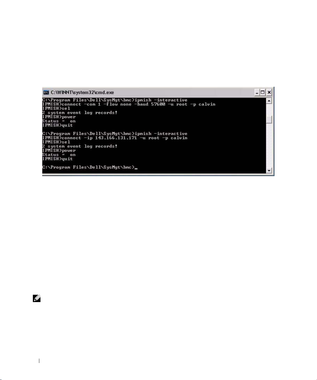
Argument
command
Specifies the command for which detailed description is required.
Figure 3-14. IPMISH help option
SOL Proxy
SOL Proxy is a simple telnet server. It allows a telnet client to interact with the hardware-designated
serial port of a remote managed system using the LAN communication channel. See Figure 3-15. With
SOL Proxy, administrators can view and change the BIOS settings over a shared LAN. In addition, you
can also access your managed system’s BMC using SOL Proxy using the Linux serial console and
Microsoft’s EMS/SAC interfaces. SOL Proxy does not support in-band or serial connection to the
managed system’s BMC.
When BIOS console redirection to serial port is enabled on the remote managed system, any application
that uses the BIOS to read from or write to the system console will have its I/O redirected to the
designated serial I/O port. When SOL is activated, the BMC firmware reads any data written to the serial
port and transmits it to the SOL Proxy as LAN packets. SOL Proxy then forwards the data to the telnet
client as TCP/IP packets.
Conversely, any keyboard activity at the telnet client is sent to the BMC by SOL Proxy. BMC then writes
the packets to the system serial I/O port.
NOTE: See your system’s User’s Guide for more information about console redirection, including hardware and
software requirements and instructions for configuring host and client systems to use console redirection.
56 Using the BMC Management Utility

The SOL Proxy communication scheme enables you to view and configure the BIOS settings of a
managed system, as well as to reset the managed system remotely using a telnet client. SOL Proxy is
installed as a daemon service and automatically starts each time the system boots. SOL Proxy can
accommodate only one telnet session at a time.
You can use a variety of telnet clients to access SOL Proxy features. For example:
• In a Windows environment, you can use a Command Prompt window as your console. However,
function keys such as <F1> and <F2> will not operate correctly with this client except on systems
running Windows Server 2003.
• In a Windows environment, you can also use any telnet application that supports VT100 or
ANSI emulation mode (such as HyperTerminal) as your console.
NOTICE: All versions of the Microsoft Windows operating system include Hilgraeve's HyperTerminal
terminal emulation software. However, the included version does not provide many functions required during
console redirection. Instead, you can use any terminal emulation software that supports VT100 or ANSI
emulation mode. One example of a full VT100 or ANSI terminal emulator that supports console redirection on
your system is Hilgraeve's HyperTerminal Private Edition 6.1 or later.
NOTE: When using HyperTerminal, you must deselect the Wrap lines that exceed terminal width check box
to avoid console redirected data that may appear to be corrupted or garbled. To deselect this feature, click
→
Properties→ Settings→ ASCII Setup…→ Wrap lines that exceed terminal width.
File
NOTE: See your system’s User’s Guide for more information about console redirection, including hardware and
software requirements and instructions for configuring host and client systems to use console redirection.
• In a Linux environment, you can use a shell such as
csh
or
ksh
as your console, or you can use any
telnet application supporting VT100 or ANSI emulation mode.
NOTE: Telnet settings must be consistent with the settings on the managed system. For example, the baud rates
and terminal modes should match.
Using the BMC Management Utility 57

You can also send the terminal break function while in console redirection. The use of this functionality
requires that the specific terminal program in use has the ability to send the break function. For example,
you can send the break signal through the Linux telnet modules by typing:
Ctrl+]send brk<Enter>
The Linux SysRq function is one example of an advanced debugging feature that is enabled by use of the
break function. See the "BIOS Configuration" section on how to use this feature. See the "Serial Console
redirection With SOL Proxy" section for more information on the SysRq feature.
To enable BIOS console redirection for use with SOLProxy:
• Configure the
PowerEdge
Console redirection
x9xx
systems. This option is available under the
attribute to
On with Console Redirection via COM2
Serial Communication
for
submenu in
BIOS setup.
• Configure the
is available under the
option is available under the
Console Redirection
Console Redirection
Integrated Devices
attribute to
menu in
Serial Port1
BIOS Setup
menu in
BIOS Setup
for PowerEdge
. Set
Serial Port 1
.
x8xx
systems. This option
to
BMC NIC
. This
Using SOL Proxy
Depending on the console you use, there are different steps for accessing SOL Proxy. Throughout this
section, the management station where the SOL Proxy is running is referred to as the SOL Proxy Server.
Initiating the SOL Proxy session using the Windows Command Prompt:
To connect and use SOL Proxy:
1
Open a Command Prompt window on your management station.
2
Enter the
and the port number that you specified in the SOL Proxy installation (the default value is 623).
For example:
telnet 192.168.1.24 623
telnet
command in the command-line and provide the IP address of the SOL Proxy server
NOTE: The IP address and port number you provide should conform to the ones defined in the SOL Proxy
configuration file. For more details, see “Configuring the SOL Proxy Configuration File.”
3
If you are prompted for a username, provide the operating system login credentials of the system
running the service:
4
Provide a password when prompted. SOL Proxy will use this combination of operating system
DSM_BMU_SOL_Proxy
username and password to authenticate you on the SOL Proxy Server. The specific authentication
scheme will depend on the operating system configuration for the SOL Proxy Server. However, if
localhost
or an IP address of 127.0.0.1 is used, it is assumed that the user has login privileges to the
current host, and is not prompted for a username and password.
5
After authentication, a login successful message and the SOL Proxy main menu prompt appear. You
are ready to use SOL Proxy. By default, you will be logged in the menu mode. See "SOL Proxy Main
Menu" for further instructions.
58 Using the BMC Management Utility
.

The following line edit functions are supported during the SOLProxy session:
1
Up- and Down- arrow keys to browse command history.
2
Left- and Right- arrow keys to move the input cursor.
Using a Linux Shell
To connect and use SOL Proxy:
1
Open a Linux shell on your management station.
2
Enter the
telnet
command and provide the IP address of the SOL Proxy Server and the port number
you specified in SOL Proxy installation. For example:
telnet 192.168.1.24 623
NOTE: The IP address and port number you provide should conform to the ones defined in the SOL Proxy
configuration file. For more details, see “Configuring the SOL Proxy Configuration File.”
3
If you are prompted for a username, provide the operating system login credentials of
SOL Proxy Server.
4
Provide a password when prompted. SOL Proxy will use this combination of operating system
username and password to authenticate you on the SOL Proxy Server. The specific authentication
scheme will depend on the operating system configuration for the SOL Proxy Server. However, if
localhost
or an IP address of 127.0.0.1 is used, it is assumed that the user has login privileges to the
current host, and is not prompted for a username and password.
5
After authentication, a login successful message and the SOL Proxy main menu prompt appear. You
are ready to use SOL Proxy. See "SOL Proxy Main Menu" for further instructions.
Using the BMC Management Utility 59

SOL Proxy Main Menu
After the telnet connection with SOL Proxy is successfully established, you are presented with the
following choices. See Figure 3-15.
Figure 3-15. SOL Proxy Main Menu Example
The SOL Proxy main menu allows you to change the SOL settings of a remote managed system’s BMC,
reboot the remote BMC, or activate console redirection.
When you select menu option 1, Connect to the Remote Server’s BMC, you are prompted for the BMC
IP address and BMC login. After you enter the required information and make a successful connection,
the internal state SLP is changed to “connected.” If you select menu options 2, 3, or 4, and the
application state is not “connected,” you are prompted to connect to a BMC.
Menu option 2 allows you to enable, disable, and configure the SOL defaults, including the minimum
user privilege level required for activating SOL and the communication baud-rate.
60 Using the BMC Management Utility

Menu options 3 and 4 allow you to establish a SOL remote console session through the SOL Proxy main
menu. Menu option 3 establishes a SOL session without changing the remote system’s state. This option
is ideal for connecting to the Microsoft SAC/EMS or the Linux console. Menu option 4 reboots the
remote managed system and establishes a SOL session. This option is best suited for performing BIOS
setup and system configuration tasks.
To exit an active SOL session, use the <~><.> character sequence. This sequence terminates SOL
and returns you to the top-level menu.
Connecting to the Remote Managed System’s BMC
NOTE: While multiple SOL sessions can be active at the same time, only one console redirection session can be
active at any given time for a managed system.
1
Select option 1 in the main menu.
2
Enter the BMC IP address of the remote managed system.
3
Provide the BMC username and password for the BMC on the managed system. The BMC username
and password must be assigned and stored in the BMC non-volatile storage. See "Configuring Your
Managed System" for more information about configuring BMC users. Only one SOL session with one
BMC is permitted at one time.
The connection status displays on the main menu. See Figure 3-16.
4
Provide the IPMI encryption key if it was configured in the BMC.
Figure 3-16. Connecting to the Remote System’s BMC
Using the BMC Management Utility 61

Configuring the SOL for the Remote Managed System
Select option 2 in the main menu.
NOTE: You must be connected to the managed system’s BMC before you can configure the SOL features. If
SOL Proxy is not yet connected to the managed system’s BMC, you are prompted for an IP address, a
username/password combination, and an IPMI encryption key. The IPMI encryption key value will be ignored if no
key was set at the BMC on the target server. See "Connecting to the Remote Managed System’s BMC" for more
information.
The SOL configuration menu appears. According to the current SOL status, the content of the SOL
configuration menu varies:
• If SOL is already enabled, the current settings are displayed and you are presented with three choices.
See Figure 3-17.
Figure 3-17. Configuring the Serial-Over-LAN for the Remote System, Example 1
• If SOL is currently disabled, the options shown in Figure 3-18 are displayed. Type Y to enable SOL or N
to keep SOL disabled. See Figure 3-18.
62 Using the BMC Management Utility

Figure 3-18. Configuring the Serial-Over-LAN for the Remote System, Example 2
• If SOL is enabled, two BMC settings are displayed:
– The communication baud-rate between the system serial port and the BMC
– The minimum BMC user privilege level required for activating console redirection
SOL Proxy displays a list of valid values for each feature, as well as the current value of the feature
enclosed in a pair of brackets. Select the number before a value to set it as the new setting, and press
<Enter> to confirm your changes. The new SOL settings are then displayed. See Figure 3-19.
Using the BMC Management Utility 63

Figure 3-19. SOL Settings, Example 3
Activating Console Redirection
Select option 3 in the main menu.
NOTE: You must be connected to the managed system’s BMC before you can configure the SOL features. If SOL
Proxy is not yet connected to the managed system’s BMC, you are prompted for an IP address and a
username/password combination. See "Connecting to the Remote Managed System’s BMC" for more information.
The remote managed system’s text console is redirected to your management station. See Figure 3-20.
NOTE: BIOS Console Redirection must be enabled on the managed system and correctly configured before SOL
can be successfully activated. See "Configuring Your Managed System" for more information.
64 Using the BMC Management Utility

Figure 3-20. Console Redirection Example
Rebooting the Managed System and Activating Console Redirection
Select option 4 in the main menu.
NOTE: You must be connected to the managed system’s BMC before you can configure the SOL features. If SOL
Proxy is not yet connected to the managed system’s BMC, you are prompted for an IP address, a
username/password combination, and an IPMI encryption key. The IPMI encryption key value will be ignored if no
key was set at the BMC on the target server. See "Connecting to the Remote Managed System’s BMC" for more
information.
The power state of the remote managed system is confirmed. If power is on, you are asked to decide
between a graceful or forceful shutdown.
Next, the power state is monitored until the status changes to on. Console redirection begins, and the
remote managed system text console is redirected to your management station. Use the escape character
sequence <~><.> to terminate console redirection and return to the top-level menu.
While the managed system reboots, you can enter the BIOS system setup program to view or configure
BIOS settings. See Figure 3-21.
NOTE: Before activating the console redirection, you must first enable the console redirection features. See
"Configuring Your Managed System" for more information.
Using the BMC Management Utility 65

Figure 3-21. Reboot Example
Getting Help
Select option 5 in the main menu to display detailed descriptions for each option. See Figure 3-22.
Figure 3-22. Sample Help Screen
Exit
Select option 6 to end your telnet session and disconnect from SOL Proxy.
66 Using the BMC Management Utility

Using SOL proxy in command mode
By default, SOL Proxy is installed for use in the menu mode by the system. See "Configuring the SOL
Proxy Configuration File" section for instructions on how to change the default settings to command mode.
Commands in SOL Proxy
SOL Proxy command mode is similar to the IPMI Shell interactive mode. In addition to supporting all
commands of the IPMI Shell interactive mode, the SOL Proxy supports the following additional
commands.
console
Synopsis
console
Description
This command allows users to establish an SOL session with the connected server.
NOTE: BMU responds with an error message if console is used before establishing an IPMI session with connect.
reboot
Synopsis
reboot[-force]
Description
This command allows you to control power configurations and establish an SOL session in one atomic
operation. It is equivalent to executing the menu command of "Reboot and Activate Console Redirection".
Options
-force
This option is used to force the system to shut down. If this option is omitted, the "reboot" command is
executed using a graceful shutdown.
Figure 3-23. reboot Option Example
Using the BMC Management Utility 67

Configuring the SOL Proxy Configuration File
Certain parameters, for IPMI Shell and SOL Proxy, must be correctly configured in the SOL Proxy
Configuration file, - SOLProxy.cfg, which is located in the default installation BMC directory.
The parameters and their descriptions are as follows:
Comments
Any line starting with a “#” is treated as a comment. For example:
#The file is an example.
IP Address
Specifies the specific IP address used to connect to SOL Proxy. This item defines what kind of
connection can be accepted to establish a SOL Proxy telnet session. There are three possible values:
•
INADDR_ANY
•
127.0.0.1
•
IP address
For example:
ip=INADDR_ANY
Port Binding
Specifies the port at which the SOL Proxy listens for incoming connections. By default, the port is set to
623 and can be modified by the user.
This item defines the port when you telnet SOL Proxy. If this item is absent, 623 is set as the default
port. For example:
port=623
—
SOL proxy listens for input on any interface on the server.
— SOL proxy listens for input on the localhost only.
—
SOL proxy listens for input on this IP address only.
Session Timeout
Specifies the time in minutes before the SOL Proxy session times out.
If there is no keyboard activity for the specified timeout period, the telnet session and the SOL session
will be closed. The timeout value is specified in minutes and can be changed during SOL Proxy
installation. For example:
session_timeout=30
Power-off Timeout
Specifies the time in seconds before the SOL Proxy gives up polling for the managed system's power
status. If the SOL Proxy issues the power off command and the system does not power off within the
specified interval, the SOL Proxy returns with a message, indicating that the SOL Proxy was unable to
power off the system due to the timeout interval.
68 Using the BMC Management Utility

NOTE: When Reboot and Activate Console Redirection is selected and power for the remote managed system is
on, a power off IPMI command is issued. The power status is then continually monitored until the power status
reports “off.” If power status remains “on” longer than this timeout period, Reboot and Activate Console
Redirection reports an error and returns to the top-level menu. This timeout value is specified in seconds and can
be changed during SOL Proxy installation.
For example:
power_off_timeout=60
Retry Interval
Specifies the period of time in seconds that the BMC waits before it tries to resend a packet. The
retry_interval unit is half a second. Therefore, a value of 2 means that the software waits one second for
the BMC to respond before it tries to resend the packet, a value of 4 means that it waits two seconds, and
so on. For example:
retry_interval=2
Retry Count
Specifies the maximum number of times that the software tries to resend a packet if it does not receive a
response from the BMC. Before each retry, the software waits for the interval specified by the
retry_interval parameter. For example:
retry_count=10
User Interface
Specifies the default settings for SOL Proxy startup. The user can edit and set this comment in the
command or menu mode. For example:
user_interface=menu
Sol Loss Silent
Specifies system behaviour when one or more SOL packets is lost. The possible values are 0 and 1. If it is
set to 0 or is absent, the system will print an error message on the screen each time an SOL packet is lost.
If it is set to 1, the system will not print error messages for loss of SOL packets. For example:
sol_loss_silent=0 or 1
Sol Loss Threshold
Specifies number of SOL packets that can be lost before SOL deactivation. The default value is 0, which
means that the system will deactivate SOL, if any SOL packets are lost. For example,
sol_loss_silent_threshold=0
Using the BMC Management Utility 69

Sdr Cache
Specifies whether the system probe information is saved. This information enhances speed of
providing sensor and System Event Log (SEL) data. The possible values are on and off. Default value is
on. For example,
sdr_cache=on
Sdrcache Path
Specifies path where the system probe information is saved. Default location is the installed
BMC directory on your hard drive. For example,
sdrcache_path=<specified path directory>
Max Session
Specifies the maximum number of concurrent SOL sessions possible. This default value is 1; any value
less than 1 will be ignored or treated as 1. You cannot set more than 20 sessions. For example,
max_session=2
Logpath
Specifies the path for storing the log files. Two log files, solproxy.log and solproxyipmi.log, are created at
the specified path. For example,
logpath=<specified location for log file>
debug
Specifies if the debug data will be logged. The default is off.
debug=off
70 Using the BMC Management Utility

Known Issues and Frequently Asked Questions
This section discusses known issues with using the BMC Management Utility, along with frequently
asked questions.
Known Issues
General Issues
• You must assign a valid BMC user name and password before you can connect to your system's
BMC using the BMC Management Utility. If you do not explicitly provide a valid BMC user name
and password when using the BMC Management Utility to log in to your system's BMC, the
BMC firmware will use a null user name and null password as defaults, resulting in a "Login Not
Authorized" error.
SOL Proxy Issues
• SOL Proxy on IP port 623 allows connections from a Web browser. However, if you connect from a
Web browser, SOL Proxy displays only jumbled and unusable data. You must close the Web
session and connect through a telnet connection to run the application.
®
• Microsoft
is enabled with EMS SAC, you will see corrupted data. As SAC does not implement hardware flow
control, you are unable to effectively use SOL Proxy to activate console redirection to EMS SAC.
This can result in corrupted screen output caused by missed characters. Slower baud rates correct
this situation and still provide good user experience.
SAC does not implement hardware control flow. Therefore, when console redirection
IPMI Shell Issues
• If you type
will receive a "command not found" error from DOS. This is because the BMU install directory is
not included in the system search path. You can execute IPMISH directly by specifying a fully
qualified path or by first navigating to the BMC directory and then executing the command. You
may also manually add the BMU install directory to the execution search path.
ipmish
from any directory other than the directory where the BMU is installed, you
Known Issues and Frequently Asked Questions 71

Frequently Asked Questions
Q: Do IPMI Shell commands correspond one-to-one to IPMI commands?
A: IPMI Shell provides only the most useful IPMI commands. It includes a definitive set of commands
that can accomplish the most common management tasks. Therefore, IPMI Shell commands may not
correspond one-to-one to IPMI commands.
Q: Can I manage a system by accessing multiple IPMI instances simultaneously?
A: Yes, you can manage a system by accessing multiple IPMI instances at the same time as long as your
system’s BMC supports more than one concurrent connection.
Q: Can my SOL Proxy server handle multiple connections at a time?
A: Yes, each SOL Proxy server can handle a maximum of 20 SOL Proxy connections simulatenously. By
default only one session is permitted. Edit solproxy.cfg and uncomment and increase the value of
max_session.
Q: How do I unlock an SOL session occupied by another user?
A: Your system’s BMC only supports one SOL session at a time. You must wait for the current user’s
session to time out before you can access a new SOL proxy session. See "Session Timeout" for more
information about configuring the session timeout parameters.
Q: Why can’t I connect to a console using the terminal emulation software included with my Microsoft
Windows
A: The version of HyperTerminal included with Windows does not provide many functions required
during console redirection. Either upgrade to HyperTerminal Private Edition 6.1 or later, or select any
other terminal emulation software that supports full configuration of VT100 or ANSI emulation mode.
Q. What is the Spanning Tree feature?
A. Most quality routers use the Rapid Spanning Tree Protocol (RSTP) to optimize performance and
remove loops. This can cause delays upto 30 seconds or more whenever a NIC is reset. Resets are known
to happen during BIOS POST, driver initialization, and some network software installation and
configuration. The delay can cause errors when running IPMISH commands. It can also cause a SOL
proxy session to become inactivated. You can configure your router to reduce or eliminate the delay by
enabling the router option edge-port (Dell™ PowerConnect™) or port fast (Cisco). This will allow the
link to remain constant and handle the optimization in real time.
72 Known Issues and Frequently Asked Questions
®
operating system?

Q: I performed a Reboot and Activate Console Redirection command using SOL Proxy, but the option
to press <F2> to enter the BIOS setup never appeared.
A: When the network switch has spanning-tree enabled, it takes as much as 30 to 40 seconds for the
spanning-tree check to make sure there are no loops in the network. During this time, packet forwarding
by the switch is blocked. Therefore, the software cannot communicate with the BMC until the spanning
tree check is complete. When the spanning tree feature is enabled on a edge-port or port fast router, the
network link can be broken for periods of time in excess of 30 seconds while the router analyzes the
network. This situation can be identified partially when the link light is off. IPMISH commands can
timeout during this process. Disable spanning-tree on the port fast router or enable the Spanning Tree
Fast option and try performing a Reboot and Activate Console Redirection command using SOL Proxy
again. You should now be able to enter BIOS setup by pressing <F2>.
Q: Why do I see a connection time-out error message when I perform the Power Reset command using
the IPMISH command line tool?
A: The spanning-tree feature described in the previous Q&A can cause problems during power
management as well. Use the solution above to help assure that power reset and other power
management commands can function without network timeouts.
Q: Why do some key and key combinations, such as <F10> and <Ctrl><Alt><Del>, not work
during console redirection?
A: Console redirection uses ANSI or VT 100/220 terminal emulation, which is limited to basic ASCII
characters. Function keys, arrow keys, and control keys are not available in the ASCII character set, and
most utilities require function keys and control keys for ordinary operations. See "Escape Key Sequences"
for more information on the same.
Q: Can you use terminal mode simultaneously with BIOS console redirection?
A: Yes. BMC terminal mode can function simultaneously with BIOS console redirection. You can escape
between the BMC’s terminal mode and the BIOS console redirection using the following
Escape sequences:
Press <Esc><q> to switch the system serial port to the BIOS console redirection text stream.
Press <Esc><(> to switch the system serial port to the BMC terminal mode text stream.
NOTE: Because you are switching back and forth between two independently active text streams, data
may be lost.
See your system User’s Guide for more information about configuring and using BIOS console
redirection and see "Terminal Mode Commands" for more information about using Terminal
Mode commands.
Known Issues and Frequently Asked Questions 73

74 Known Issues and Frequently Asked Questions

BMC Management Utility Error Codes
The following is a list of error messages for the BMC Management Utility. In case of a functional
failure, an error message will be printed to stderr. The text of the error message is listed in the
Message column in Table A-1.
Errors will always be printed in a parsable format such as:
Error (<hex-code>):<message>!
The following is an example:
Error(0xC1):Invalid Command!
Table A-1. BMC Management Utility Error Codes
Code Classification Message Description IPMI Error
A1h Connection
errors.
Invalid authentication type. Authentication type
A2h Communication
errors.
Data error. Data packet format error. 0xC6,
Not connected. Not connected to a
A3h Authorization
errors.
Login not authorized. Invalid BMC
Connection timeout. BMC not responding.
error.
Communication error. Network stack or serial
communication error.
remote server yet.
Insufficient privilege for
command.
Insufficient privilege
level to execute
command.
username/password.
0xC7,
0xC8,
0xCA
0xD4
0x86
BMC Management Utility Error Codes 75

Table A-1. BMC Management Utility Error Codes (continued)
Code Classification Message Description IPMI Error
A5h Initialization
errors.
Access denied. Trying to access the proxy
Unknown language. Unknown language code.
Invalid IP address. IP resolving error.
Session buffer limit
A6h
A8h
Unrecognized command. Unrecognized command.
Conflicting option. Conflicting option (-last
Invalid parameter. Invalid parameter.
A7h Parameter value
Parameter out of range
Parameter out of
Invalid data field. Invalid data field. 0xCC
Invalid index value. Index cannot be zero or a
First index larger than the
First index larger than total
Syntax errors. Command syntax error. Unable to parse
errors.
Authentication failure. Request for a session
from the local or remote
proxy was rejected.
from a forbidden IP
address.
Length exceeds the limit
exceeded.
Parameter out of range. Parameter out of range. 0xC9
(1-255).
range(1-65535)
last.
SEL records.
of telnet input.
command.
and -max).
The value is out of range
(1-255).
The value is out of range
(1-65535).
negative number.
The first index is larger
than the last.
The first index is larger
than the total SEL
records.
76 BMC Management Utility Error Codes

Table A-1. BMC Management Utility Error Codes (continued)
Code Classification Message Description IPMI Error
A8h H/W or F/W
errors.
Sensor not present. Request sensor, data, or
Sensor command error. Command illegal for
Firmware error. Command response
Destination error. Cannot deliver request to
Device error. Device specific (OEM)
A9h Processing errors
(transient errors
that may
disappear upon
retry of
command).
Destination timeout error. BMC timeout while
BMC out of storage space. BMC out of storage space
Invalid reservation ID. Invalid reservation ID. 0xC5
Duplicate command. Cannot execute
SDR busy. Sensor Data Record
Device busy. Device in firmware
BMC unavailable. BMC initialization in
Bad BMC state. Request not supported in
Unsupported command. Unsupported operation. 0xC1
0xCB
record not present.
0xCD
specified sensor or record
type.
0xCE
could not be provided.
0xD3
destination.
0x01–0x7E
errors.
BMC busy. BMC out of processing
resources.
processing command
required to process
command.
duplicated request.
Repository in update
mode.
update mode.
progress.
present BMC state.
0xC0
0xC3
0xC4
0xCF
0xD0
0xD1
0xD2
0xD5
BMC Management Utility Error Codes 77

Table A-1. BMC Management Utility Error Codes (continued)
Code Classification Message Description IPMI Error
BMC out of sessions. No session slots are
available for connection
request.
AEh Unexpected IPMI
errors.
Unspecified error. Unspecified error. 0xFF
AFh Unknown error Unknown error. Unknown error.
Invalid LUN. Invalid Logical Unit
Number (LUN) in
request.
0x81,
0x82,
0x83
0xC2
78 BMC Management Utility Error Codes

Terminal Mode Commands
This appendix provides information about terminal mode commands.
Terminal mode allows you to directly connect to the system's Baseboard Management Controller
(BMC) using a serial port connection and execute text-based commands. Two types of text
commands are supported:
• A limited selection of text commands
• Standard binary Intelligent Platform Management Interface (IPMI) hex-ASCII commands
Configuring Terminal Mode
NOTE: Terminal Mode can be configured through Server Administrator and the Deployment Toolkit (DTK).
To configure Terminal Mode through Server Administrator, complete the following steps:
Log in to the Server Administrator home page for the target system.
1
2
Click the
3
Click the
4
Click the
5
The
6
Click the
In the
7
Click the
You can configure the Connection Mode Setting, Baud Rate, Flow Control, Channel Privilege Level
Limit attributes on this screen.
• The Serial communication connection mode for the BMC must be set to
terminal Mode
•
External Serial Connector
systems. This option is available under the
•Disable the
navigate to
•Set
Integrated Devices
System
object.
Main System Chassis
Remote Access
BMC Information
Configuration
Configuration
Terminal Mode Settings
RAC serial Console
Serial
Serial Port 1
tab, click
for Dell™ PowerEdge™
from
for PowerEdge
menu.
object.
object.
window is displayed.
tab.
Serial Port
must be configured and set to
if you have a DRAC 5 installed. Login to the DRAC GUI,
Remote Access
x8xx
.
button.
x8xx
and
x9xx
Serial Communication
, and disable
systems. This option is available in the
systems.
Remote Access
submenu in the BIOS Setup.
Enable Serial console
Direct Connect
for PowerEdge
.
BIOS Setup
x9xx
, in the
Terminal Mode Commands 79

Using Terminal Mode
Use the Terminal Mode feature to perform the following tasks:
• Power the server on or off.
• Reset the server.
• Retrieve the server's health status.
• Configure and retrieve the server management subsystems boot options.
• Configure and retrieve the BMC's terminal mode configuration.
• Execute any platform supported binary command specified in the IPMI specification using the
hex-ASCII format.
NOTE: Many of the Terminal Mode features described in this section require an extensive knowledge of IPMI. It is
strongly recommended that Terminal Mode users have an advanced understanding of IPMI before using the
commands documented in this section.
Security Information
Access to the BMC using terminal mode is governed by the proper setup of user names and password.
See "Configuring Your Managed System" for more information. A session must be established with the
BMC prior to accepting any terminal mode commands. A limited selection of text commands and binary
hex-ASCII commands that are assigned the lowest IPMI privilege level are available prior to session
establishment with the BMC.
Since the terminal mode password is sent using clear text, it is highly desirable that the terminal mode
session takes place in a secure location over a secure link by using a direct connection.
Syntax
Terminal mode messages follow the general syntax below:
[<message data>]<newline sequence>
Each terminal mode message must be preceded with the left bracket "start” character and must be ended
with a right bracket “stop” character and the appropriate input new-line sequence.
No input characters are accepted until the start character has been received.
NOTE: Hex-ASCII commands can either use upper or lower-case letters for ASCII representations of hex digits.
Command Length
Terminal mode messages are limited to a maximum length of 122 characters. This includes the left- and
right-brackets, but not control characters.
80 Terminal Mode Commands

Character Support
Terminal mode messages are composed of standard printable ASCII characters. All other characters are
treated as illegal characters.
Special Character Handling — <Esc> character
The <Esc> character deletes an entire message prior to submission to the BMC for processing. If line
editing is enabled, and the <Esc> key is followed by an input newline sequence, the BMC responds by
outputting an output newline sequence. Otherwise, the BMC looks for the next start character.
Special Character Handling — <Delete> or <Backspace> character
The <Backspace> or <Delete> key deletes the last character entered if the message has not been
submitted to the BMC yet.
Special Character Handling — Line Continuation character
Long IPMI messages can be split across multiple lines by using the line continuation "\" character
followed immediately by an input newline sequence. Line continuation character usage is supported for
both text and hex-ASCII commands.
Special Character Handling — Illegal characters
Any illegal characters received by the BMC clear the message in progress and the BMC looks for the next
start character.
Hex-ASCII Command Format
Binary IPMI commands are sent and received as a series of case-insensitive hex-ASCII pairs, where each
is separated from the preceding pair by a single space character. Table B-1 lists the terminal mode
requests to BMC and Table B-2 lists the terminal mode responses from BMC. The following is an
example of a binary IPMI request message:
[18 00 22]<newline sequence>
Table B-1. Terminal Mode Request to BMC
Byte Explanation
1 [7:2] – Net Function (even)
[1:0] – Responder’s LUN
2 [7:2] – Requester’s Sequence Number
[1:0] – Bridge field
3 Command Number
4:N Data
Terminal Mode Commands 81

Table B-2. Terminal Mode Response from BMC
Byte Explanation
1 [7:2] – Net Function (odd)
[1:0] – Responder’s LUN
2 [7:2] – Requester’s Sequence Number
[1:0] – Bridge field
3 Command Number
4 Completion Code
5:N Data
Text Command Format
Text commands do not support the bridging and sequence number fields present in the hex-ASCII
commands. In addition, text commands are preceded by a prefix consisting of the string SYS. Table B-3
lists the terminal mode text commands and Table B-4 lists the terminal mode configuration.
Examples
Hex-ASCII command example (IPMI Reset Watchdog Cmd):
[18 00 22]<CR>
[1C 00 22 00]<CR-LF>
Text command example:
[SYS TMODE]<CR>
[OK TMODE]<CR-LF>
82 Terminal Mode Commands

Table B-3. Terminal Mode Text Commands
Command Switches Description
SYS PWD -U USERNAME
<password>
-U activates a terminal mode session. USERNAME corresponds to
the ASCII text for the username. <password> represents a
printable password (up to 16 characters). If <password> is not
provided, then a Null password (all binary 0’s) is submitted.
Passwords are case sensitive.
Either the SYS PWD command or the Activate Session IPMI
message must be successfully executed before any command or
IPMI messages are accepted.
NOTE: A modem connection may be automatically dropped if
multiple bad passwords are entered.
-N <password> -N represents a Null username and <password> represents a
printable password (up to 16 characters). If <password> is not
provided, then a Null password (all binary 0’s) is submitted.
Passwords are case sensitive.
Either the SYS PWD command or the Activate Session IPMI
message must be successfully executed before any command or
IPMI messages are accepted.
NOTE: A modem connection may be automatically dropped if
multiple bad passwords are entered.
-X -X immediately logs out any presently active session.
NOTE: Entering an invalid password with -U or -N does not allow you
to log on.
SYS TMODE Used as a no-op confirm that Terminal Mode is active. The BMC
returns an OK response followed by TMODE.
SYS SET BOOT
XX YY ZZ AA BB
Sets the boot flags to direct a boot to the specified device following
the next IPMI command or action initiated reset or power-on.
XX…BB represent five hex-ASCII encoded bytes, which are the
boot flags parameter in the Boot Option Parameters.
Upon receiving this command, the BMC automatically sets the
valid bit in the boot options and sets all the Boot Initiator
Acknowledge data bits to 1b.
Terminal Mode Commands 83

Table B-3. Terminal Mode Text Commands (continued)
Command Switches Description
SYS SET
BOOTOPT XX
YY…NN
SYS GET
BOOTOPT XX
YY ZZ
This is a text version of the IPMI Set System Boot Options
command. It allows any of the boot option parameters to be set,
not just the boot flags. XX YY…NN represent the hex-ASCII
encoding for the data bytes that are passed in the Set System Boot
Options request.
XX — Parameter valid.
[7] — 1b = Mark parameter invalid/locked.
0b = Mark parameter valid/unlocked.
[6:0] — Boot option parameter selector .
YY…NN — Boot Option Parameter Data.
Passing 0-bytes of parameter data allows the parameter valid bit to
be changed without affecting the present parameter setting.
This is a text version of the IPMI Get System Boot Options
command. It allows any of the boot option parameters to be
retrieved.
XX YY ZZ represents the hex-ASCII for the data bytes that are
passed in the Get System Boot Options request.
The BMC returns the data from the command in hex-ASCII
format.
XX—Parameter selector.
[7]—Reserved.
[6:0]—Boot option parameter selector.
YY—Set Selector.
[7:0]—Selects a particular block or set of parameters under the
given parameter selector.
Write as 00h if the parameter does not use a Set Selector.
ZZ—Block Selector.
Selects a particular block within a set of parameters
Write as 00h if the parameter does not use a Block Selector.
NOTE: There are no IPMI-specified Boot Options parameters that
use the block selector. However, this field is provided for consistency
with other configuration commands and as a placeholder for future
extension of the IPMI specification.
84 Terminal Mode Commands

Table B-3. Terminal Mode Text Commands (continued)
Command Switches Description
SYS SET TCFG Returns the Terminal Mode Configuration bytes where XX and YY
represent hex-ASCII encoding for the volatile version of data bytes
1 and 2 as specified in Table B-4, and AA BB represent hex-ASCII
encoding of the non-volatile version.
V:XX <output termination sequence>
N:AA BB <output termination sequence>
-V XX YY Sets the volatile Terminal Mode Configuration. XX and YY
represent hex-ASCII encoding for data bytes 1 and 2 as specified in
Table B-4. The BMC returns the same output as for SYS SET
TCFG, above.
-N XX YY Sets the non-volatile Terminal Mode Configuration. XX and YY
represent hex-ASCII encoding for data bytes 1 and 2 as specified in
Table B-4. The BMC returns the same output as for SYS SET
TCFG, above.
SYS RESET Directs the BMC to perform an immediate system hard reset.
SYS POWER
OFF
SYS POWER ON Causes the BMC to initiate an immediate system power on.
Directs the BMC to perform an immediate system power off.
Terminal Mode Commands 85

Table B-3. Terminal Mode Text Commands (continued)
Command Switches Description
SYS HEALTH
QUERY
Causes the BMC to return a high level version of the system health
status in terse format. The BMC returns a string with the following
format if the command is accepted.
PWR:zzz H:xx T:xx V:xx PS:xx C:xx D:xx S:xx O:xx
Where:
PWR is system POWER state.
H is overall Health.
T is Temperature.
V is Voltage.
PS is Power Supply subsystem.
C is cooling subsystem (Fans).
D is Hard Drive/RAID Subsystem.
S is physical Security.
O is Other (OEM).
zzz is: ON, OFF (soft-off or mechanical off), SLP (sleep - used
when sleep level cannot be distinguished), S4, S3, S2, S1, ??
(unknown).
and xx is: ok, nc, cr, nr, uf, or ?? where:
ok = OK (monitored parameters within normal operating ranges).
nc = non-critical ("warning": hardware outside
normal operating range).
cr = critical ("fatal": hardware exceeding specified
ratings).
nr = non-recoverable ("potential damage": system
hardware in jeopardy or damaged).
uf = unspecified fault (fault detected, but severity unspecified).
?? = status not available/unknown (typically because system power
is OFF).
86 Terminal Mode Commands

Table B-3. Terminal Mode Text Commands (continued)
Command Switches Description
SYS HEALTH
QUERY
SYS IDENTIFY Causes the BMC to indicate the system’s location in a rack of
SYS IDENTIFY -ON<XX> Causes the BMC to indicate the system’s location, for example,
SYS IDENTIFY -OFF Causes the BMC to stop indicating the system’s location. This has
-V Causes the BMC to return a high level version of the system health
status in multi-line verbose format. The BMC returns a string of
the following format:
SYS Health:xx<output termination sequence>.
Power: ON, OFF (soft-off or mechanical off), SLEEP (sleep - used
when can't distinguish sleep level), S4, S3, S2, S1, Unknown.
Temperature:xx<output termination sequence>.
Voltage:xx<output termination sequence>.
PowerSystem:xx<output termination sequence>.
Cooling:xx<output termination sequence>.
Drives:xx<output termination sequence>.
Security:xx<output termination sequence>.
Other:xx<output termination sequence>.
Where xx is:
OK (monitored parameters within normal operating ranges).
Non-critical (warning: hardware outside normal operating range).
Critical (fatal :hardware exceeding specified ratings).
Non-recoverable (potential damage: system hardware in jeopardy
or damaged).
Unspecified fault (fault detected, but severity unspecified).
Unknown (status not available/unknown (typically because system
power is OFF).
systems, for example, with a blinking LED or beep. The BMC will
indicate the system’s location only for 15 seconds. This is a text
version of the optional Chassis Identify command.
with a blinking LED or beep for a specific period of time.
XX is an optional hex-ASCII byte representing the number of
seconds the BMC is to cause the system to identify itself. If XX is
not provided, the BMC will indicate the system’s location only for
15 seconds. This is a text version of the optional Chassis Identify
command.
no effect if the system is not currently identifying itself. This is a
text version of the optional Chassis Identify command.
Terminal Mode Commands 87

Table B-4. Terminal Mode Configuration
Byte Explanation
1 [7:6]—Reserved.
[5]—Line Editing.
0b = Disable.
1b = Enable (Factory default).
[4]—Reserved.
[3:2]—Delete control (only applies when line editing is enabled).
00b = BMC outputs a <Delete> character when <Backspace> or <Delete> is
received.
01b = BMC outputs a <Backspace>< SP ><Backspace> sequence when
<Backspace> or
<Delete> is received (Factory default).
[1]—Echo control0b = No echo 1b = Echo (BMC echoes characters it receives)
(Factory default).
[0]—Handshaking—BMC outputs a [SYS]<newline> after receiving each terminal
mode IPMI message and is ready to accept the next message.
0b = Disable.
1b = Enable (Factory default).
2 [7:4] - Output newline sequence (BMC to console). Selects what characters the BMC
uses as the <newline> sequence when the BMC writes a line to the console in
Terminal Mode.
0h = no termination sequence.
1h = <CR-LF> (Factory default)
2h = <NULL>
3h = <CR>
4h = <LF-CR>
5h = <LF>
All other = reserved
[3:0] - Input newline sequence (Console to BMC). Selects what characters the console
uses as the newline sequence when writing to the BMC in Terminal Mode.
0h = reserved
1h = <CR> (Factory default)
2h = <NULL>
All other = reserved
88 Terminal Mode Commands

Escape Key Sequences
Console redirection uses ANSI or VT100/220 terminal emulation, which are limited to basic
ASCII characters. There are no function keys, arrow keys, or control keys in this character set.
However, most BIOS software requires the use of function keys and control keys for ordinary actions.
Specific function keys and escape keys can be emulated by using a special key sequence, called an
escape sequence, to represent a specific key.
Use the Escape sequences, listed in the following table, for keys while setting console redirection in
BIOS through serial port. These keys are also listed during BIOS POST. Press the spacebar to pause
and view the list. Supported sequences are also listed in the history of the system’s telnet client.
Table C-1. Escape sequences for specific keys
Key Supported sequences
F10 <Esc><0>
F12 <Esc><@>
<Ctrl><M> <Esc><Ctrl><M>
<Ctrl><H> <Esc><Ctrl><H>
<Ctrl><I> <Esc><Ctrl><I>
<Ctrl><J> <Esc><Ctrl><J>
<Alt><X> <Esc><X><X>
<Ctrl><Alt><Del> <Esc><R><Esc><r><Esc>
<R>
Escape Key Sequences 89

90 Escape Key Sequences

Serial Port Console Redirection
Serial Communication
For PowerEdge x9xx servers, serial console redirection can be accomplished using COM1 or COM2.
Console Redirection Via COM1
To activate serial console redirection via COM1, you must configure the following settings:
Set Serial Communication-> Serial Communication to On with Console Redirection via COM1
Set Serial Communication-> External Serial Connector to COM1
Console Redirection Via COM2
Console Redirection via COM2 can be used to redirect either to the external connector or to the
remote access device, such as a BMC or DRAC 5, for Serial Over LAN (SOL) communication.
To activate serial console redirection via COM2, you must configure the following settings:
Set Serial Communication-> Serial Communication to On with Console Redirection via COM2
Set Serial Communication-> External Serial Connector to COM2
NOTE: If the console redirection is used for SOL then the External Serial Connector setting does not need to
be configured.
When using COM2 for console redirection regardless of whether you redirect to the external
connector or for SOL, the BIOS reads the SOL baud rate from the BMC and uses that setting to
activate console redirection. SOL baud rate can be configured using the Dell Deployment Toolkit,
OMSA, DRAC, or the BMU.
Serial Terminal Communication to BMC or DRAC
Serial Terminal Mode allows you to directly connect to the BMC or DRAC using a serial port
connection and execute text-based commands. Refer to the Appendix B for information about
configuring your BMC and DRAC for Serial Terminal Communication as well as available Terminal
Mode Commands.
In Terminal Mode, the BMC or the DRAC, if present, support Escape key sequences that allow
switching between the Serial Terminal Connection and the connection to the system COM2 port.
This can be combined with the Console Redirection via COM2 (see "Console Redirection Via
COM2") to switch between viewing the system console redirection and communicating to BMC or
DRAC to execute the terminal commands such as system reset.
Serial Port Console Redirection 91

NOTE: For this combined functionality, Serial Communication baud rate and the SOL baud rate must be set to the
same value.
When in terminal mode, to switch the connection to the system COM2 port use:
<Esc> +<Shift> <q>
When connected to the system COM2 port, to go back to the terminal mode use:
<Esc> +<Shift> <9>
SPCR Table
The Serial Port Console Redirection (SPCR) table provides information about how the system firmware
and service processor use the out-of-band (OOB) management port. For example, if the OOB
Management port is a serial port, the SPCR table contains information such as serial port number, baud
terminal type, and other settings used for OOB communication. The SPCR table is read by the Special
Administrative Console (SAC) for console redirection and configures itself automatically during a
bootable CD installation.
The SPCR table is automatically enabled if the system service processor supports Emergency
Management Services (EMS) such as console redirection. If it is not configured automatically, you must
configure SPCR to match BMC settings by adding the following parameters to the unattend.txt file.
NOTE: The unattend.txt file is automatically created after installation.
[Data]
EMSPort
EMSBaudrate
Where,
EMSPort = Port used for serial communication. For example, COM1 or COM2.
EMSBaudrate = Configured baud rate for communication. The minimum supported baud rates for
supported Dell™ PowerEdge™ systems is 19200.
Serial Console redirection With SOL Proxy
Configuring Linux for Serial Redirection During Boot
The "SysRq key" is a key sequence that allows basic commands to be passed directly to the kernel for
debugging. Under some circumstances, it can also be used to reboot remote managed systems. The serial
console uses the RS-232 break function as the SysRq key. A "break" is a period of no transmission on the
serial line. To configure the "Sysrq" key in systems running Linux, follow the instructions given below:
NOTE: The following instructions are specific to the Linux GRand Unified Bootloader (GRUB). Similar changes
would be necessary for using a different boot loader.
92 Serial Port Console Redirection

NOTE: In configuring the client VT100 emulation window, you must set the window or application that is displaying
the redirected console to 25 rows x 80 columns to ensure proper text display; otherwise, some text screens may be
garbled.
Edit the file /etc/grub.conf, as follows. See the sample file that follows, which shows the changes
described in this procedure.
Add the following two new lines in the
1
general settings
section of the file:
serial --unit=0 --speed=19200
terminal --timeout=10 serial
Append two options to the kernel line:
2
kernel ............. console=ttyS0,19200
If the
3
/etc/grub.conf
contains a
splashimage
directive, you must comment it out.
This sample file, using a baud rate of 19200, is an example. The following maximum baud rates are
allowed for BMC serial communication and SOL:
• 19200 for PowerEdge 1425SC and other PowerEdge
• 57600 for PowerEdge
• 115200 for PowerEdge
x9xx
systems without Dell Remote Access Controller 5 (DRAC 5).
x9xx
systems with DRAC 5.
x8xx
systems.
Serial Port Console Redirection 93

Table D-1. Sample File: /etc/grub.con
# grub.conf generated by anaconda
#
Note that you do not have to rerun grub after making changes to this file
# NOTICE: You do not have a /boot partition. This means that
# all kernel and initrd paths are relative to /, e.g.
# root (hd0,0)
# kernel /boot/vmlinuz-version ro root=/dev/sdal
# initrd /boot/initrd-version.img
#boot=/dev/sda
default=0
timeout=10
#splashimage=(hd0,2)/grub/splash.xpm.gz
serial --unit=0 --speed=19200
terminal --timeout=10 serial
title Red Hat Linux Advanced Server (2.4.9-e.3smp)
root (hd0,0)
kernel /boot/vmlinuz-2.4.9-e.3smp ro root=/dev/sda1 hda=ide-scsi
console=tty0 console=ttyS0,19200
initrd /boot/initrd-2.4.9-e.3smp.img
title Red Hat Linux Advanced Server-up (2.4.9-e.3
root (hd0,00)
kernel /boot/vmlinuz-2.4.9-e.3 ro root=/dev/sda1 s
initrd /boot/initrd-2.4.9-e.3.im
Additional information for editing the grub.conf:
1
You may need to disable GRUB's graphical interface and use the text-based interface instead;
otherwise, the GRUB screen will not be displayed in BMU console redirection. To do so, comment out
the line starting with
2
If you have multiple options in GRUB and you want all of them to start a console session through the
BMU serial connection, add
console=ttyS0,19200
splashimage
.
console=ttyS1,19200
added to only the first option.
94 Serial Port Console Redirection
to all options. The preceding example shows

Enabling Login to the Console After Boot
Edit the file /etc/inittab, as follows:
Add a new line to configure a getty on the COM1 serial port:
co:2345:respawn:/sbin/agetty -h -L 19200 ttyS0 vt100
See the sample file, which shows the addition of the new line.
Table D-2. Sample File: /etc/innitab
#
# inittab This file describes how the INIT process should set up
# the system in a certain run-level.
#
# Author: Miquel van Smoorenburg, <miquels@drinkel.nl.mugnet.org
# Modified for RHS Linux by Marc Ewing and Donnie Barnes
#
# Default runlevel. The runlevels used by RHS are:
# 0 - halt (Do NOT set initdefault to this)
# 1 - Single user mode
# 2 - Multiuser, without NFS (The same as 3, if you do not have
# networking)
# 3 - Full multiuser mode
# 4 - unused
# 5 - X11
# 6 - reboot (Do NOT set initdefault to this)
#
id:3:initdefault:
# System initialization.
si::sysinit:/etc/rc.d/rc.sysinit
l0:0:wait:/etc/rc.d/rc 0
l1:1:wait:/etc/rc.d/rc 1
l2:2:wait:/etc/rc.d/rc 2
l3:3:wait:/etc/rc.d/rc 3
l4:4:wait:/etc/rc.d/rc 4
l5:5:wait:/etc/rc.d/rc 5
l6:6:wait:/etc/rc.d/rc 6
Serial Port Console Redirection 95

Table D-2. Sample File: /etc/innitab (continued)
# Things to run in every runlevel.
ud::once:/sbin/update
# Trap CTRL-ALT-DELETE
ca::ctrlaltdel:/sbin/shutdown -t3 -r now
# When our UPS tells us power has failed, assume we have a few
# minutes of power left. Schedule a shutdown for 2 minutes from now.
# This does, of course, assume you have power installed and your
# UPS is connected and working correctly.
pf::powerfail:/sbin/shutdown -f -h +2 "Power Failure; System Shutting Down"
# If power was restored before the shutdown kicked in, cancel it.
pr:12345:powerokwait:/sbin/shutdown -c "Power Restored; Shutdown Cancelled"
# Run gettys in standard runlevels
co:2345:respawn:/sbin/agetty -h -L 19200 ttyS0 vt100
1:2345:respawn:/sbin/mingetty tty1
2:2345:respawn:/sbin/mingetty tty2
3:2345:respawn:/sbin/mingetty tty3
4:2345:respawn:/sbin/mingetty tty4
5:2345:respawn:/sbin/mingetty tty5
6:2345:respawn:/sbin/mingetty tty6
# Run xdm in runlevel 5
# xdm is now a separate service
x:5:respawn:/etc/X11/prefdm -nodaemon
96 Serial Port Console Redirection

Edit the file /etc/securetty, as follows:
Add a new line, with the name of the serial tty for COM1:
ttyS0
See the sample file, which shows the addition of the new line.
Table D-3. Sample File: /etc/securetty
vc/1
vc/2
vc/3
vc/4
vc/5
vc/6
vc/7
vc/8
vc/9
vc/10
vc/11
tty1
tty2
tty3
tty4
tty5
tty6
tty7
tty8
tty9
tty10
tty11
ttyS0
Serial Port Console Redirection 97

98 Serial Port Console Redirection

Glossary
The following list defines or identifies technical
terms, abbreviations, and acronyms used in your
system documents.
adapter card
An expansion card that plugs into an expansion-card
connector on the system's system board. An adapter
card adds some specialized function to the system by
providing an interface between the expansion bus and
a peripheral device. Examples of adapter cards include
network cards, sound cards, and SCSI adapters.
ANSI
Abbreviation for American National
Standards Institute.
API
Abbreviation for application program interface, which
is a set of routines, protocols, and tools for building
software applications that act as an interface between
the operating system and application programs.
Argument
The value supplied with an option, such as in the
following command line instance:
utilname --option=argument
ARP
Acronym for Address Resolution Protocol, which is a
method for finding a host’s Ethernet address from its
Internet address.
ASCII
Acronym for American Standard Code for Information
Interchange. A text file containing only characters from
the ASCII character set (usually created with a text
editor, such as Notepad in Microsoft
®
Windows®), is
called an ASCII file.
asset tag code
An individual code assigned to a system, usually by a
system administrator, for security or tracking purposes.
autoexec.bat file
The
autoexec.bat
file is executed when you boot your
system (after executing any commands in the
config.sys
file). This start-up file contains commands
that define the characteristics of each device connected
to your system, and it finds and executes programs
stored in locations other than the active directory.
backup
A copy of a program or data file. As a precaution, you
should back up your system's hard drive on a regular
basis. Before making a change to the configuration of
your system, you should back up important start-up
files from your operating system.
baud rate
A measurement of data transmission speed. For
example, modems are designed to transmit data at one
or more specified baud rate(s) through the COM
(serial) port of a system.
binary
A base-2 numbering system that uses 0 and 1 to
represent information. The system performs
operations based on the ordering and calculation of
these numbers.
BIOS
Acronym for basic input/output system. Your system's
BIOS contains programs stored on a flash memory chip.
The BIOS controls the following:
• Communications between the microprocessor and
peripheral devices, such as the keyboard and the
video adapter
• Miscellaneous functions, such as system messages
Glossary 99

bit
The smallest unit of information interpreted by
your system.
BMC
Abbreviation for baseboard management controller,
which is a controller that provides the intelligence in
the IPMI structure.
boot routine
When you start your system, it clears all memory,
initializes devices, and loads the operating system.
Unless the operating system fails to respond, you can
reboot (also called warm boot) your system by pressing
<Ctrl><Alt><Del>; otherwise, you must perform a
cold boot by pressing the reset button or by turning the
system off and then back on.
bootable diskette
You can start your system from a diskette. To make a
bootable diskette on a system running Windows, insert
a diskette in the diskette drive, type
sys a:
at the
command line prompt, and press <Enter>. Use this
bootable diskette if your system will not boot from the
hard drive.
your system's disk drives; when a program makes a
request to a disk drive for data that is in the cache, the
disk-cache utility can retrieve the data from RAM faster
than from the disk drive.
CD-ROM
Abbreviation for compact disc read-only memory. CD
drives use optical technology to read data from CDs.
CDs are read-only storage devices; you cannot write
new data to a CD with standard CD drives.
CHAP
Acronym for Challenge-Handshake Authentication
Protocol, an authentication scheme used by PPP
servers to validate the identity of the originator of the
connection upon connection or any time later.
CLI
Abbreviation for command line interface.
Command
The combination of an option and argument or just an
option if no argument is required, such as in the
following command line instances:
utilname --option
bus
An information pathway between the components of a
system. Your system contains an expansion bus that
allows the microprocessor to communicate with
controllers for all the various peripheral devices
connected to the system. Your system also contains an
address bus and a data bus for communications
between the microprocessor and RAM.
byte
Eight contiguous bits of information, the basic data
unit used by your system.
cache
A fast storage area that keeps a copy of data or
instructions for quicker data retrieval. For example,
your system's BIOS may cache ROM code in faster
RAM. Or, a disk-cache utility may reserve RAM in
which to store frequently accessed information from
100 Glossary
utilname --option=argument
command line instance
A series of valid commands, options, and arguments
typed in the command line. For example, the
Deployment Toolkit utility name and all necessary
options and arguments as they are entered through the
OS shell:
A:>utilname --option --option=argument
COMn
The device names for the first through fourth serial
ports on your system are COM1, COM2, COM3, and
COM4. The default interrupt for COM1 and COM3
is IRQ4, and the default interrupt for COM2 and
COM4 is IRQ3. Therefore, you must be careful when
configuring software that runs a serial device so that
you don't create an interrupt conflict.
 Loading...