

Page 1

Dell PowerVault
NX3500 System
Administrator’s Guide
Page 2

Notes and Cautions
NOTE: A NOTE indicates important information that helps you make better use of
your computer.
CAUTION: A CAUTION indicates potential damage to hardware or loss of data if
instructions are not followed.
____________________
Information in this publication is subject to change without notice.
© 2012 Dell Inc. All rights reserved.
Reproduction of these materials in any manner whatsoever without the written permission of Dell Inc.
is strictly forbidden.
Trademarks used in this text: Dell™, the DELL logo, and PowerVault™ are trademarks of Dell Inc.
Microsoft
trademarks of Microsoft Corporation in the United States and/or other countries. Symantec™,
NetBackup™, and Backup Exec™ are trademarks of Symantec Corporation. CommVault
Simpana
Other trademarks and trade names may be used in this publication to refer to either the entities claiming
the marks and names or their products. Dell Inc. disclaims any proprietary interest in trademarks and
trade names other than its own.
2012 - 01 Rev. A02
®
, Windows®, Internet Explorer®, and Windows Server® are either trademarks or registered
®
®
are either trademarks or registered trademarks of CommVault.
and
Page 3

Contents
1 Introduction . . . . . . . . . . . . . . . . . . . . . . . 17
About This Document . . . . . . . . . . . . . . . . . . 17
Other Information You May Need
. . . . . . . . . . . . 18
Terms Used in the Document . . . . . . . . . . . . . . 19
PowerVault NX3500 Architecture
Key Features
PowerVault NX3500 Views
System Components
NAS Controller Pair
PowerVault MD Storage
. . . . . . . . . . . . . . . . . . . . 23
. . . . . . . . . . . . . 23
. . . . . . . . . . . . . . . . . . . 25
. . . . . . . . . . . . . . . . . 25
. . . . . . . . . . . . . . 26
BPS . . . . . . . . . . . . . . . . . . . . . . . . . 26
SAN Network
. . . . . . . . . . . . . . . . . . . . 26
Internal Network . . . . . . . . . . . . . . . . . . 26
Internal Network A
Internal Network B
. . . . . . . . . . . . . . . . . 27
. . . . . . . . . . . . . . . . . 27
LAN or Client Network . . . . . . . . . . . . . . . 27
2 Setting Up Your PowerVault
NX3500 Solution
Setting Up the Environment . . . . . . . . . . . . . . . 30
Choosing the Topology
Completing the NAS System Setup
Worksheet
. . . . . . . . . . . . . . . . . . . 29
. . . . . . . . . . . . . . . 30
. . . . . . . . . . . . . . . . . . . . . 42
. . . . . . . . . . . . 21
Contents 3
Page 4

NAS System Setup Worksheet . . . . . . . . . . . 42
Preparing Your Management Station. . . . . . . . 45
Installing the Solution in the Rack . . . . . . . . . . . 45
Setting Up Your MD Storage Solution
. . . . . . . 45
Creating Disk Groups . . . . . . . . . . . . . . . . 46
Creating Virtual Disks
Creating a Host Group
. . . . . . . . . . . . . . . . 49
. . . . . . . . . . . . . . . 51
Creating Host-to-Virtual Disk Mappings . . . . . . 52
Running the PowerVault NASCU . . . . . . . . . . . . 53
Installing the PowerVault NASCU
. . . . . . . . . 53
Launching the PowerVault NASCU . . . . . . . . . 54
NAS Manager Configuration Wizard
. . . . . . . . 64
Accessing the NAS Manager Web Interface
PowerVault NAS Manager
Configuration Wizard . . . . . . . . . . . . . . . . 66
3 Accessing the Dell PowerVault
NAS Manager . . . . . . . . . . . . . . . . . . . . . 69
Browser Requirements . . . . . . . . . . . . . . . 69
. . . 64
4 Monitoring PowerVault NX3500. . . . . . . 73
4 Contents
NAS Manager Overview
Action Bar
. . . . . . . . . . . . . . . . . . . . . . 71
Admin Tabs
Admin Tree
. . . . . . . . . . . . . . . . . 70
. . . . . . . . . . . . . . . . . . . . . 71
. . . . . . . . . . . . . . . . . . . . . 71
Toolbar . . . . . . . . . . . . . . . . . . . . . . . 71
Page
. . . . . . . . . . . . . . . . . . . . . . . . . 71
Search Bar
. . . . . . . . . . . . . . . . . . . . . 72
Dashboard . . . . . . . . . . . . . . . . . . . . . . . . 74
Page 5

Status . . . . . . . . . . . . . . . . . . . . . . . . 74
Capacity. . . . . . . . . . . . . . . . . . . . . . . 76
Current Performance
Load Balancing
. . . . . . . . . . . . . . . . 76
. . . . . . . . . . . . . . . . . . . 77
Network Performance
Client Network Throughput—Read or Write
Operations Per Second
. . . . . . . . . . . . . . . . . . 78
. . . . 78
. . . . . . . . . . . . . . . 78
Network Aggregated Throughput . . . . . . . . . 78
Load Balancing . . . . . . . . . . . . . . . . . . . . . 79
Over Time
. . . . . . . . . . . . . . . . . . . . . . 79
Client Connections . . . . . . . . . . . . . . . . . 79
Usage Considerations
CIFS Connections
Hardware
. . . . . . . . . . . . . . . . . . . . . . . . 83
Component Status
Capacity
. . . . . . . . . . . . . . . . . . . . . . . . . 85
Space Utilization
Quota Usage
Replication
. . . . . . . . . . . . . . . . . . . . 86
. . . . . . . . . . . . . . . . . . . . . . . . 86
Active Remote Replication Jobs
Remote Replication Report
. . . . . . . . . . . . . . . 81
. . . . . . . . . . . . . . . . . . 82
. . . . . . . . . . . . . . . . . 84
. . . . . . . . . . . . . . . . . . 85
. . . . . . . . . . 86
. . . . . . . . . . . . . 86
5 Monitoring PowerVault NX3500
Events . . . . . . . . . . . . . . . . . . . . . . . . . . . 87
Event Search . . . . . . . . . . . . . . . . . . . . . . 88
Defining Queries
. . . . . . . . . . . . . . . . . . . . 89
Contents 5
Page 6

6 Using Volumes, Shares, and Quotas . . . 91
NAS Volumes. . . . . . . . . . . . . . . . . . . . . . . 91
Usage Considerations
Solution 1
. . . . . . . . . . . . . . . . . . . . . . 94
Solution 2 . . . . . . . . . . . . . . . . . . . . . . 95
Solution 3
. . . . . . . . . . . . . . . . . . . . . . 95
Managing NAS Volumes
Adding a NAS Volume . . . . . . . . . . . . . . . 96
Modifying a NAS Volume
Removing a NAS Volume
. . . . . . . . . . . . . . . 93
. . . . . . . . . . . . . . 95
. . . . . . . . . . . . . . 96
. . . . . . . . . . . . . . 96
Shares and Exports
Managing NFS Exports
Managing CIFS Shares
. . . . . . . . . . . . . . . . . . . 97
. . . . . . . . . . . . . . . 97
. . . . . . . . . . . . . . . 99
Setting Access Control Lists and Share Level
Permissions on FluidFS
CIFS Storage Administrator Account
. . . . . . . . . . . . . . . . 100
. . . . . . . 100
Active Directory Configuration . . . . . . . . . . 100
Setting ACLs or SLPs on a CIFS Share
. . . . . . 100
Access Using CIFS . . . . . . . . . . . . . . . . 102
Configuring CIFS Shares Level Permissions
Removing a CIFS Share
. . . . . . . . . . . . . . 104
Resetting Local Administrator Password
. . . 103
. . . . . 104
Quotas . . . . . . . . . . . . . . . . . . . . . . . . . 105
Default Quotas
. . . . . . . . . . . . . . . . . . 105
User or Group Specific Quotas . . . . . . . . . . 105
Quota Types
. . . . . . . . . . . . . . . . . . . . 106
6 Contents
Page 7

7 Protecting Data on PowerVault
NX3500 . . . . . . . . . . . . . . . . . . . . . . . . . 107
Replication. . . . . . . . . . . . . . . . . . . . . . . . 108
NAS Replication
Activating Replication . . . . . . . . . . . . . . . 109
Setting Up a Replication Partner
Adding a Replication Policy
Managing Replication Policies . . . . . . . . . . . 110
Deleting a Replication Policy
Removing a Replication Partner
. . . . . . . . . . . . . . . . . . 108
. . . . . . . . . . 110
. . . . . . . . . . . . 110
. . . . . . . . . . . . 110
. . . . . . . . . . 111
Managing Snapshots
Snapshots
Activating Snapshots
. . . . . . . . . . . . . . . . . . 111
. . . . . . . . . . . . . . . . . . . . . . 111
. . . . . . . . . . . . . . . . 112
Creating a Snapshot (Without a Policy) . . . . . . 112
Adding or Modifying a Snapshot Policy
Accessing Snapshots
. . . . . . . . . . . . . . . 112
. . . . . . 112
Restoring Data . . . . . . . . . . . . . . . . . . . 113
Restoring a NAS Volume From a Snapshot
. . . . 113
Deleting a Snapshot . . . . . . . . . . . . . . . . 113
Backing Up and Restoring Data . . . . . . . . . . . . . 114
Supported Applications
Enabling NDMP Support
Changing NDMP Password
Modifying DMA Servers List
. . . . . . . . . . . . . . . 116
. . . . . . . . . . . . . . 116
. . . . . . . . . . . . 117
. . . . . . . . . . . . 117
Specifying NAS Volume for Backup . . . . . . . . 118
Displaying Active NDMP Jobs
Terminating an Active NDMP Job
NDMP Design Considerations
Using Antivirus Applications
Overview
. . . . . . . . . . . . . . . . . . . . . . 119
. . . . . . . . . . . 118
. . . . . . . . . 118
. . . . . . . . . . . 119
. . . . . . . . . . . . . . 119
Contents 7
Page 8

Supported Applications. . . . . . . . . . . . . . 119
Adding Antivirus Hosts . . . . . . . . . . . . . . 119
Enabling Antivirus Support Per CIFS Share
. . . 120
8 Managing the PowerVault NX3500 . . . . 121
Managing the System . . . . . . . . . . . . . . . . . 123
Managing Client Access. . . . . . . . . . . . . . . . 123
Viewing the Defined Subnets
Modifying a Subnet . . . . . . . . . . . . . . . . 124
Removing a Subnet
. . . . . . . . . . . . . . . . 124
. . . . . . . . . . . 124
Managing Administrator Users
Adding an Administrator
Changing the Administrator’s Password
Modifying an Administrator
. . . . . . . . . . . . 125
. . . . . . . . . . . . . 125
. . . . . 125
. . . . . . . . . . . . 126
Modifying an Administrator's
E-Mail Filter Rules. . . . . . . . . . . . . . . . . 126
Removing an Administrator . . . . . . . . . . . . 126
Managing Local Users . . . . . . . . . . . . . . . . . 127
Adding Local Users
. . . . . . . . . . . . . . . . 127
Modifying Local Users . . . . . . . . . . . . . . 128
Deleting Local Users
Changing the Password
Managing Local Groups
Adding a Local Group
Modifying a Local Group
Deleting a Local Group
Authentication
. . . . . . . . . . . . . . . . . . . . . 130
. . . . . . . . . . . . . . . 128
. . . . . . . . . . . . . . 128
. . . . . . . . . . . . . . . . 128
. . . . . . . . . . . . . . . 129
. . . . . . . . . . . . . 129
. . . . . . . . . . . . . . 129
Configuring an Identity Management
Database
. . . . . . . . . . . . . . . . . . . . . 130
8 Contents
Page 9

Enabling User Authentication Through
an NIS Database
. . . . . . . . . . . . . . . . . . 131
Enabling User Authentication Through
an LDAP Database
. . . . . . . . . . . . . . . . . 131
Disabling the Use of an External UNIX
Identity Management Database . . . . . . . . . . 132
Active Directory
. . . . . . . . . . . . . . . . . . . . . 132
Synchronizing PowerVault NX3500 With
the Active Directory Server
Configuring the Active Directory Service
. . . . . . . . . . . . . . . 132
. . . . . 133
Network Configuration Overview . . . . . . . . . . . . 133
Accessing the System
. . . . . . . . . . . . . . . 133
Performance and Static Routes . . . . . . . . . . 134
Configuring DNS . . . . . . . . . . . . . . . . . . . . . 136
Adding DNS Servers
. . . . . . . . . . . . . . . . 136
Removing DNS Servers. . . . . . . . . . . . . . . 136
Adding DNS Domains
. . . . . . . . . . . . . . . . 137
Deleting DNS Domains . . . . . . . . . . . . . . . 137
Managing Static Routes . . . . . . . . . . . . . . . . . 137
Adding Static Routes
. . . . . . . . . . . . . . . . 137
Modifying a Static Route . . . . . . . . . . . . . . 137
Deleting a Static Route
Defining File System Protocols
. . . . . . . . . . . . . . . 138
. . . . . . . . . . . . . 138
Configuring CIFS Parameters . . . . . . . . . . . . . . 138
Configuring General CIFS Parameters
Configuring Advanced CIFS Parameters
. . . . . . . 138
. . . . . . 139
Configuring System Time Parameters
Changing the Time Zone
. . . . . . . . . . . . . . 140
. . . . . . . . . . 140
Contents 9
Page 10

Manually Configuring the Current Date
and Time
. . . . . . . . . . . . . . . . . . . . . . 140
Removing an NTP Server . . . . . . . . . . . . . . . 141
Synchronizing PowerVault NX3500 With
a Local NTP Server
. . . . . . . . . . . . . . . . 141
9 Maintaining the PowerVault NX3500 . . . 143
Shutting Down the PowerVault NX3500 System. . . . 143
Turning On the PowerVault NX3500 Solution
Installing the Service Pack
. . . . . . . . . . . . . . 145
. . . . . 144
Expanding the PowerVault NX3500
Storage Capacity
Prerequisites
Adding LUNs to PowerVault NX3500
Running Diagnostics on PowerVault
Online Diagnostics
Offline Diagnostics
Reinstalling the PowerVault NX3500
Replacing a PowerVault NX3500 Controller
Prerequisites
. . . . . . . . . . . . . . . . . . . . 146
. . . . . . . . . . . . . . . . . . . 146
. . . . . . . 147
. . . . . . . . . 148
. . . . . . . . . . . . . . . . 148
. . . . . . . . . . . . . . . . 149
. . . . . . . . . 150
. . . . . . 151
. . . . . . . . . . . . . . . . . . . 151
Detaching the PowerVault NX3500
Controller
. . . . . . . . . . . . . . . . . . . . . 151
Removing and Replacing the PowerVault
NX3500 Controller . . . . . . . . . . . . . . . . . 152
Attaching the PowerVault NX3500
Controller . . . . . . . . . . . . . . . . . . . . . 153
10 Contents
Page 11

10 Troubleshooting . . . . . . . . . . . . . . . . . . . 155
Troubleshooting CIFS Issues . . . . . . . . . . . . . . 155
Clients Cannot Access CIFS Files
CIFS Access Denied
. . . . . . . . . . . . . . . . 155
CIFS ACL Corruption . . . . . . . . . . . . . . . . 156
CIFS Client Clock Skew
. . . . . . . . . . . . . . . 156
CIFS Client Disconnection on File Read
CIFS Client General Disconnection. . . . . . . . . 157
CIFS Client Login Failure
CIFS Connection Failure
. . . . . . . . . . . . . . 157
. . . . . . . . . . . . . . 157
CIFS Delete-On-Close Denial . . . . . . . . . . . . 158
CIFS File Access Denied
. . . . . . . . . . . . . . 158
CIFS File Sharing Conflict
CIFS Guest Account Invalid . . . . . . . . . . . . 159
CIFS Locking Inconsistency
CIFS Maximum Connections Reached
CIFS Share Does Not Exist . . . . . . . . . . . . . 160
CIFS Path Share Not Found
CIFS Write to Read Only Volume . . . . . . . . . . 161
Troubleshooting NFS Issues . . . . . . . . . . . . . . . 161
Cannot Mount NFS Export
NFS Export Does Not Exist . . . . . . . . . . . . . 164
NFS File Access Denied
. . . . . . . . . . . . . . 164
NFS Insecure Access to Secure Export
NFS Mount Fails Due to Export Options . . . . . . 165
NFS Mount Fails Due to Netgroup Failure
NFS Mount Path Does Not Exist
NFS Owner Restricted Operation
NFS Write to Read-Only Export
NFS Write to Read-Only Volume
NFS Write to Snapshot
. . . . . . . . . . . . . . . 168
NFS Access Denied to a File or Directory
. . . . . . . . . 155
. . . . . . 157
. . . . . . . . . . . . . . 158
. . . . . . . . . . . . 159
. . . . . . . 159
. . . . . . . . . . . . . 160
. . . . . . . . . . . . . 161
. . . . . . 165
. . . . . 166
. . . . . . . . . . 167
. . . . . . . . . . 167
. . . . . . . . . . . 168
. . . . . . . . . . 168
. . . . . 168
Contents 11
Page 12

Troubleshooting Replication Issues . . . . . . . . . . 169
Replication Configuration Error
. . . . . . . . . . 169
Replication Destination Cluster is Busy . . . . . 169
Replication Destination FS is Busy
Replication Destination is Down
. . . . . . . . 170
. . . . . . . . . 170
Replication Destination is Not Optimal . . . . . . 170
Replication Destination Volume is Busy
Reclaiming Space
. . . . . . . . . . . . . . . . . 171
Replication Destination Volume
is Detached . . . . . . . . . . . . . . . . . . . . 171
Replication Disconnection
. . . . . . . . . . . . 171
Replication Incompatible Versions . . . . . . . . 172
Replication Internal Error
Replication Jumbo Frames Blocked
. . . . . . . . . . . . . 172
. . . . . . . 172
Replication Destination Does Not
Have Enough Space . . . . . . . . . . . . . . . 172
Replication Source is Busy
. . . . . . . . . . . . 173
Replication Source is Down . . . . . . . . . . . 173
Replication Source is Not Optimal
. . . . . . . . 173
Replication Source Volume is Busy
Reclaiming Space. . . . . . . . . . . . . . . . . 174
12 Contents
Troubleshooting Active Directory Issues
. . . . . . . 174
Group Quota For an Active Directory
User Does Not Work
Active Directory Authentication
. . . . . . . . . . . . . . . 174
. . . . . . . . . 175
Troubleshooting Active Directory
Configuration . . . . . . . . . . . . . . . . . . . 175
Troubleshooting BPS Issues
. . . . . . . . . . . . . . 176
Backup Power Supply LED Displays
a Solid Amber Light
. . . . . . . . . . . . . . . . 176
Backup Power Supply LED Flashes
Green and Amber . . . . . . . . . . . . . . . . . 177
Backup Power Supply Displays a
Blinking Amber LED
. . . . . . . . . . . . . . . . 177
Page 13

BPS LED Is Off . . . . . . . . . . . . . . . . . . . 178
Troubleshooting NAS File Access and
Permissions Issues
. . . . . . . . . . . . . . . . . . . 178
Cannot Change the Ownership of a
File or a Folder
Cannot Modify NAS Files
Mixed File Ownership Denied
. . . . . . . . . . . . . . . . . . . 178
. . . . . . . . . . . . . . 179
. . . . . . . . . . . 179
Problematic SMB Access From a
Linux Client . . . . . . . . . . . . . . . . . . . . . 179
Strange UID and GID Numbers on
Dell NAS System Files . . . . . . . . . . . . . . . 180
Troubleshooting Networking Issues . . . . . . . . . . 181
Name Server Unresponsive
. . . . . . . . . . . . 181
Specific Subnet Clients Cannot Access
the PowerVault NX3500 System . . . . . . . . . . 181
Troubleshooting DNS Configurations
. . . . . . . . 182
Determining the IQN of the PowerVault
NX3500 Controllers Using CLI . . . . . . . . . . . 182
Troubleshooting RX and TX Pause
Warning Messages. . . . . . . . . . . . . . . . . 182
Troubleshooting NAS Manager Issues
NAS Dashboard is Delayed
NAS System Time is Wrong
Cannot Connect to the NAS Manager
. . . . . . . . . 183
. . . . . . . . . . . . . 183
. . . . . . . . . . . . . 183
. . . . . . . 184
Blank Login Screen . . . . . . . . . . . . . . . . . 185
Troubleshooting Backup Issues . . . . . . . . . . . . . 185
Troubleshooting Snapshots
. . . . . . . . . . . . 185
Troubleshooting an NDMP Internal Error . . . . . 187
Troubleshooting System Issues
Troubleshooting System Shutdown
NAS Container Security Violation
. . . . . . . . . . . . . 188
. . . . . . . . . 188
. . . . . . . . . 189
Contents 13
Page 14

Multiple Errors Received During
File System Format
Associating LUN Names to Virtual Disks
Identifying Controllers
. . . . . . . . . . . . . . . . 189
. . . . . 191
. . . . . . . . . . . . . . 191
Troubleshooting NAS Configuration
Utility Issues
. . . . . . . . . . . . . . . . . . . . . . 192
Error Received While Running the
PowerVault NASCU
. . . . . . . . . . . . . . . . 192
Cannot Launch PowerVault NX3500
NAS Configuration Utility
. . . . . . . . . . . . . 193
11 Command Line Interface . . . . . . . . . . . . 195
Overview . . . . . . . . . . . . . . . . . . . . . . . . 195
12 Internationalization . . . . . . . . . . . . . . . . 201
14 Contents
Accessing the CLI
. . . . . . . . . . . . . . . . . . . 196
CLI Menu Options . . . . . . . . . . . . . . . . . . . 197
Overview . . . . . . . . . . . . . . . . . . . . . . . . 201
Unicode Client Support Overview
NFS Clients
. . . . . . . . . . . . . . . . . . . . . . . 202
. . . . . . . . . . . 201
CIFS Clients. . . . . . . . . . . . . . . . . . . . . . . 202
Unicode Configuration Parameters
Unicode Configuration Limitations
File Size and Directory Name
Clients Compatibility Problems
Japanese Compatibility Issues
. . . . . . . . . . 202
. . . . . . . . 203
. . . . . . . . . . . 203
. . . . . . . . . . 203
. . . . . . . . . . 203
Page 15

13 Frequently Asked Questions . . . . . . . . . 205
NDMP . . . . . . . . . . . . . . . . . . . . . . . . . . 205
Replication
. . . . . . . . . . . . . . . . . . . . . . . . 206
A BPS Alarms . . . . . . . . . . . . . . . . . . . . . . 209
B Cabling Recommendation . . . . . . . . . . . 213
Contents 15
Page 16

16 Contents
Page 17

1
Introduction
The Dell PowerVault NX3500 clustered network attached storage (NAS)
system is a high-availability storage solution. The solution aggregates multiple
NAS controllers in a cluster and presents them to UNIX, Linux, and
Microsoft Windows clients as one virtual file server.
About This Document
This document provides information on the features available to the storage
administrator. It is organized as follows.
Chapter Description
Introduction Provides information on the PowerVault NX3500 cluster
solution architecture and features.
Setting Up Your
PowerVault NX3500
Solution
Accessing the Dell
PowerVault NAS
Manager
Monitoring
PowerVault NX3500
Monitoring
PowerVault NX3500
Events
Using Volumes,
Shares, and Quotas
Protecting Data on
PowerVault NX3500
Provides instructions on setting up the PowerVault NX3500, the
various topologies, and cabling options. It also includes the
detailed setup procedure and available configuration options.
Provides an overview of the NAS Manager web console and
instructions for accessing it.
Provides descriptions and procedures for monitoring the
PowerVault NX3500.
Provides procedures for searching events and defining queries.
Provides instructions for managing NAS volumes, shares,
and quotas.
Provides procedures for configuring data protection options
such as, snapshots, replication, and backup agent.
Introduction 17
Page 18

Chapter Description
Managing the
PowerVault NX3500
Maintaining the
PowerVault NX3500
Troubleshooting Provides information on troubleshooting your NAS
Command Line
Interface
Internationalization Provides information about unicode support in
BPS Alarms Contains additional information on troubleshooting the Dell
NAS Setup Worksheet Provides a worksheet that will help you set up and configure
Provides procedures and descriptions about the initial
configuration, system information, users management,
license management, system time, networking, protocols,
authentication, monitoring configuration, and maintenance.
Provides procedures for shutting down, powering up,
upgrading, and running diagnostics.
storage solution.
Provides basic information for using the PowerVault
NX3500 CLI.
PowerVault NX3500.
Backup Power Supply (BPS).
your solution.
Other Information You May Need
Document Description
Getting Started Guide Provides an overview of system features, setting up your
solution, and technical specifications. This document is
shipped with your system and is also available at
support.dell.com/manuals.
Hardware Owner's
Manual
Rack Installation
Instructions
Online Help Provides information about configuring and managing the
Provides information about solution features and describes
how to troubleshoot the system and install or replace system
components. This document is available at
support.dell.com/manuals.
Describes how to install your system into a rack. This
document is shipped with your rack solution and is also
available at support.dell.com/manuals.
NAS Manager. The online help is integrated with the system
and can be accessed from the NAS Manager.
18 Introduction
Page 19

Terms Used in the Document
Table 1-1. PowerVault NAS System Terms
Term Description
Backup Power
Supply
Client access VIP Virtual IP addresses that clients use to access CIFS shares and
Controller (NAS
controller or nodes)
Controller pair Two NAS controllers that are configured as pair in a
Data Management
Application (DMA)
Dell PowerVault
Modular Disk
Storage Manager
(MDSM)
Fluid File System High-performance, scalable file system software installed on
Host Port Identifier Unique ID used to identify hosts in a network.
Internal network A
(peer connection)
Internal network B
(internal
management or
IPMI)
Provides back up battery power in the event of a power loss.
NFS exports hosted by a PowerVault NAS system. The
PowerVault NAS system supports multiple client access
Virtual IPs (VIPs).
NAS appliance installed with the Dell Fluid File System
(FluidFS) software.
PowerVault NAS clustered system. Cache data is mirrored
between the paired NAS controllers.
Also known as the Backup Application Server.
The management software that ships with the PowerVault
MD32x0i or MD36x0i array.
NAS controllers.
The PowerVault NX3500's internal network consists of two
independent Gigabit Ethernet ports. The internal network is
the infrastructure for PowerVault NX3500 clustering,
including the heartbeat monitor, data transfer, and mirroring
information between the controllers.
The PowerVault NX3500 internal management network (also
known as internal network b) connects both controllers. All
administrative related functions and controller reboots are
performed on this network.
Introduction 19
Page 20

Table 1-1. PowerVault NAS System Terms
Term Description
LAN or client
network (primary
network)
NAS storage pool Virtual disks created on the PowerVault MD32x0i or MD36x0i
NAS volume (NAS
container or virtual
volume)
NAS replication Replication between two PowerVault NAS systems or between
NAS replication
partners
Network Data
Management
Protocol
Peer controller The peer NAS controller with which a specific NAS controller
Power module
(battery unit)
PowerVault
MD3xx0i
PowerVault NAS
Configuration
Utility (NASCU)
NAS Manager The web-based user interface, which is part of the PowerVault
PowerVault NAS
system
The network through which clients access NAS shares or exports.
The PowerVault NAS system is connected to customer’s IT
environment and its NAS clients using this network.
storage arrays dedicated to the PowerVault NX3500 system.
A virtualized volume that consumes storage space in the NAS
storage pool. Administrators can create CIFS shares and NFS
exports on a NAS volume and share them with authorized users.
A PowerVault NAS system supports multiple NAS volumes.
two NAS volumes.
PowerVault NAS systems participating in a replication activity.
Network Data Management Protocol (NDMP) used for
backup and restore.
is paired in a PowerVault NAS system.
One of the battery units in a BPS.
Refers to the PowerVault MD3200i, MD3220i, MD3600i,
MD3620i iSCSI storage solutions.
The setup wizard used to initially discover and configure a
PowerVault NAS system. This utility is only used for the initial
setup.
NX3500 software, used to manage the PowerVault NAS system.
A fully configured, highly-available and scalable NAS
appliance, providing NAS (CIFS and/or NFS) services, which
is comprised of a pair of NAS controllers, a BPS, a PowerVault
storage subsystem, and the NAS Manager.
(continued)
20 Introduction
Page 21

Table 1-1. PowerVault NAS System Terms
Term Description
Standby controller A NAS appliance that is installed with the FluidFS software
but not part of a cluster. For example, a new or replacement
controller from the Dell factory is considered as a standby
controller.
SAN network (iSCSI
network)
The network that carries the block level (iSCSI) traffic and to
which the storage subsystem is connected.
(continued)
NOTE: It is recommended that this network be isolated from the
LAN or client network.
PowerVault NX3500 Architecture
The PowerVault NX3500 combined with MD3xxxi provides you with a unified
storage solution (see Figure 1-1). This solution provides you with access to
both block and file storage (see Figure 1-2).
The PowerVault NX3500 clustered NAS solution consists of a pair of
controllers and the PowerVault Modular Disk (MD) iSCSI storage array. In
addition, both controllers are protected by BPS, which helps protect data
during power failure.
Each controller has:
• Two connections (four for the solution) to the customer's LAN or
client network.
• Two connections (four for the solution) to the customer's SAN network.
• Two controller peer to peer connections for the cluster's internal network.
Introduction 21
Page 22
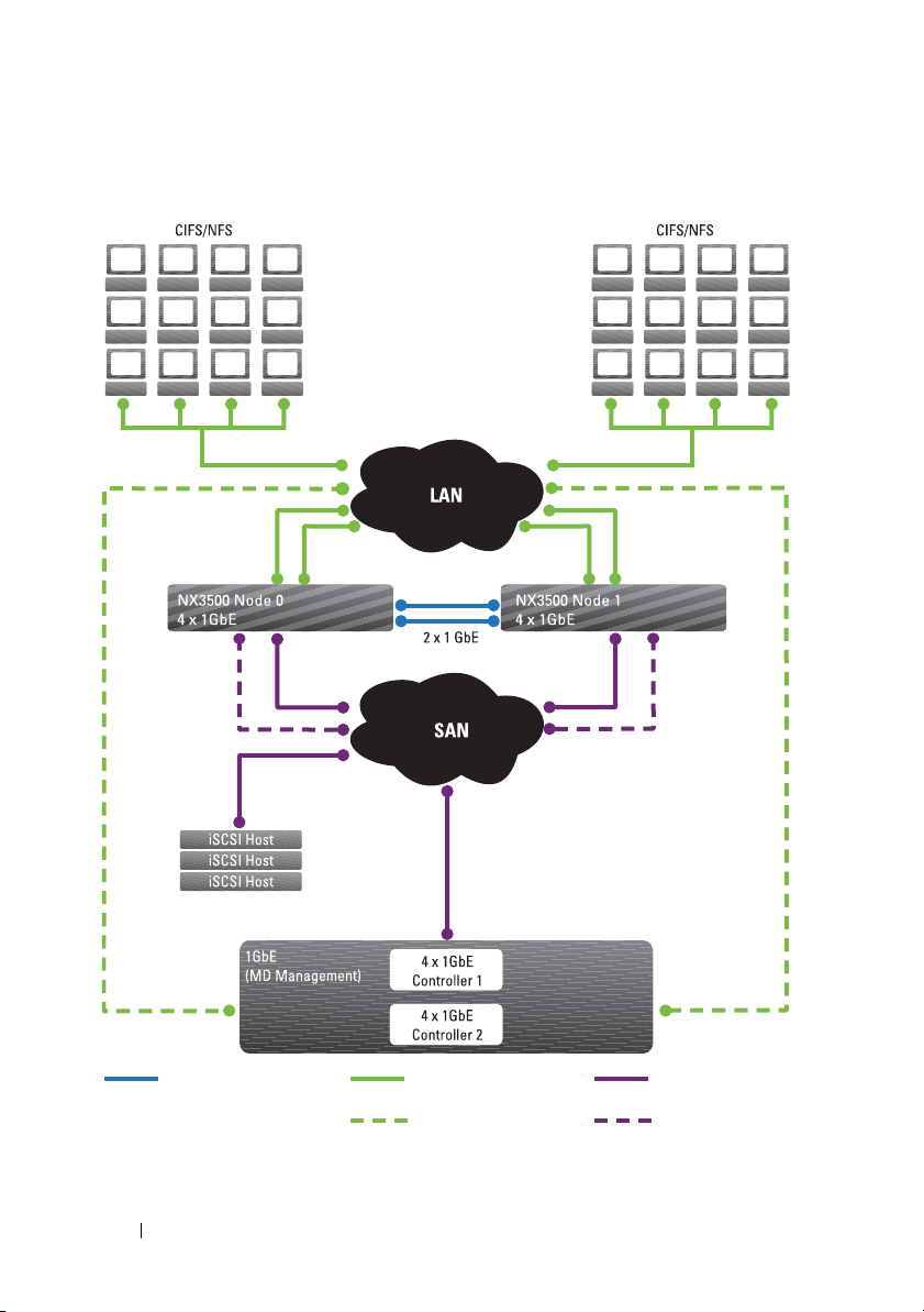
Figure 1-1. PowerVault NX3500 Architecture
Peer Connection
(Internal Network A)
Client Network
Management
Connection From MD
Array
iSCSI Network
Internal Network B
22 Introduction
Page 23

Key Features
The PowerVault NX3500:
• Helps administrators expand existing capacity and improve performance
when needed, without impacting the applications or users.
• Provides administrative functions for storage administrators who perform
day-to-day system operations and storage management.
• Has a distributed file system, which creates a single interface to the data.
• Uses a quad core processor per controller.
• Is capable of storing terabytes in a single file system.
• Allows for dynamic increase in capacity.
• Has a centralized, easy to use, web-based NAS management console.
• Has on-demand virtual storage provisioning.
• Has granular disk space management.
• Is capable of providing user-accessible Point-In-Time snapshots.
•Is capable of sharing files with Microsoft Windows, Linux, and UNIX users.
• Offers flexible, automated online replication and disaster recovery.
• Features built-in performance monitoring and capacity planning.
PowerVault NX3500 Views
You can access the PowerVault NX3500 as a client or an administrator
depending on the access privileges you have.
NOTE: It is recommended that you do not attempt to log on to both the CLI and NAS
Manager at the same time.
Introduction 23
Page 24
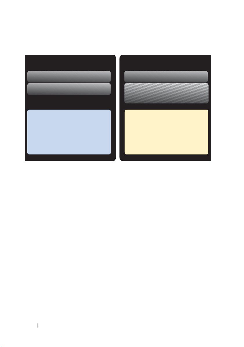
Figure 1-2. File-Level Storage and Block-Level Storage
NX3500 NAS Configuration Utility
NAS Manager
File Management
Block Management
Modular Disk Configuration Utility
Modular Disk Storage Manager
Wizard-based installation
Configure NAS network IP
Create and manage volumes and shares
Performance monitoring
Set up snapshots and replication
NDMP backup
Configure iSCSI storage array
Map virtual disks
Monitor and manage component status,
capacity, host, mappings, arrays and
virtual disks
Provision MD iSCSI storage for NAS
Define NAS host in MD iSCSI array
Client View
To the client, the PowerVault NX3500 presents itself as a single file-server
with a single file system, IP address, and name. The PowerVault NX3500's
global file system serves all users concurrently without performance
constraints. It offers end users the freedom to connect to the PowerVault
NX3500 using their respective operating system's NAS protocols.
• NFS protocol for UNIX users.
• CIFS protocol for Windows users.
Administrator View
As an administrator, you can use either the CLI or the NAS Manager to
configure or modify system settings, such as configuring protocols, adding
users, and setting permissions.
The NAS Manager provides access to system functionality, using standard
internet browsers.
24 Introduction
Page 25

System Components
The PowerVault NX3500 system consists of:
• Hardware
– NAS controller pair
– MD PowerVault storage
– Backup power supply
•Network
– SAN network
– Internal network
– LAN or client network
NAS Controller Pair
The PowerVault NX3500 clustered NAS solution consists of two NAS
controllers configured as a pair. This redundant configuration ensures that
there is no single point of failure. The controllers handle load balancing of
client connections, manage read-write operations, perform caching, and
interface with servers and workstations. The cluster and its internal networks
are consolidated using a virtual IP.
The PowerVault NX3500 software is installed on both controllers. The
software is a complete package, consisting of an operating system, volume
management, distributed file system, and clustering technology.
Read-write operations are handled through mirrored non-volatile RAM
(NVRAM). Mirroring the cache data between the paired NAS controllers,
ensures a quick response to clients' requests, while maintaining complete data
integrity. Data from the cache to permanent storage is transferred
asynchronously through optimized data-placement schemes.
Each controller is equipped with a 12 GB RAM, most of which is used for
caching. The file system uses the cache efficiently to provide fast and reliable
writes and reads. Writing or modifying files occurs first in the cache. Data is
then mirrored to the peer controller’s cache. This feature ensures that all
transactions are duplicated and secured.
Introduction 25
Page 26

PowerVault MD Storage
The controllers connect to the PowerVault MD iSCSI storage array, which is a
RAID subsystem. RAID storage subsystems are designed to eliminate single
points of failure. Each active component in the storage subsystem is
redundant and hot-swappable. The solution supports typical RAID
configurations including RAID 0, RAID 1, RAID 5, RAID 6, and RAID 10.
BPS
The BPS provides continuous power to the controllers. Each controller
receives its power from a dedicated BPS and from the power grid. The
controllers regularly monitor the BPS battery status, which requires the BPS
to maintain a minimum level of power for normal operation. The BPS has
sufficient battery power to allow the controllers to safely shut down.
The BPS enables the controllers to use the cache as NVRAM. The BPS
provides the clustered solution enough time to write all the data from the
cache to the disk if the controller experiences a loss of power.
NOTE: You can view the BPS events on the NAS Manager.
SAN Network
The SAN network is a critical part of the PowerVault NX3500 solution. The
controller pair that resides on the SAN network communicates to the storage
subsystem using the iSCSI protocol. The PowerVault NX3500 communicates
on the SANa and SANb networks, rendering a high availability (HA) design.
Internal Network
The PowerVault NX3500 solution requires an internal network for peer-topeer data transfer and management. To achieve complete data distribution
and to maintain HA, each controller must have access to its peer controller.
The internal network achieves this goal.
The internal network is classified into internal network A and internal network B.
NOTE: Ensure that the IP addresses you assign to internal network A and internal
network B are from a private IP space and do not conflict with other subnets on
your network.
26 Introduction
Page 27

Internal Network A
PowerVault NX3500's internal network A is comprised of two independent
Gigabit Ethernet ports. The internal network is the infrastructure for the
PowerVault NX3500 clustering, and includes heartbeat monitoring, data
transfer, and mirroring of information between the controllers' caches. The
internal network also distributes data evenly across all LUNs in the system.
NOTE: Internal network A is also referred to as peer-to-peer connections. The
network uses point-to-point cable connections.
Internal Network B
Internal network B is the PowerVault NX3500 internal management network,
which is plugged into the SAN switch and connects both controllers. All
administrative related functions are performed on this network.
In the event where the controllers lose communication with each other but
continue to function independently (known as the split-brain situation), the
PowerVault management network automatically resets the suspected
controller. This prevents the split-brain situation and ensures data integrity.
LAN or Client Network
After the initial configuration, a virtual IP (VIP) address connects the
PowerVault NX3500 to the client or LAN network.
The VIP address allows clients to access the PowerVault NX3500 as a single
entity, thereby providing access to the file system. It enables the PowerVault
NX3500 to perform load balancing between controllers, and ensures that the
service continues even if a controller fails.
The LAN or client network is comprised of two Gigabit Ethernet ports on
each controller, which connect to the LAN or client network switches. The
solution can have a maximum of four VIPs that serve the system. For more
information, see “Setting Up Your PowerVault NX3500 Solution” on page 29.
The PowerVault NX3500 solution is administered using the LAN or client
network on the NAS Management VIP.
Introduction 27
Page 28

28 Introduction
Page 29

2
Setting Up Your PowerVault NX3500 Solution
This chapter describes the procedure to configure the Dell PowerVault
NX3500 NAS cluster solution and integrate it into your environment.
A successful configuration of the PowerVault NX3500 involves:
• Setting up the environment (see "Setting Up the Environment" on
page 30).
• Installing the solution in a rack.
• Setting up the MD storage solution (see "Setting Up Your MD Storage
Solution" on page 45).
• Installing and running the PowerVault NAS configuration utility (see
"Running the PowerVault NASCU" on page 53).
• Initializing the filesystem.
• Utilizing the system.
Setting Up Your PowerVault NX3500 Solution 29
Page 30
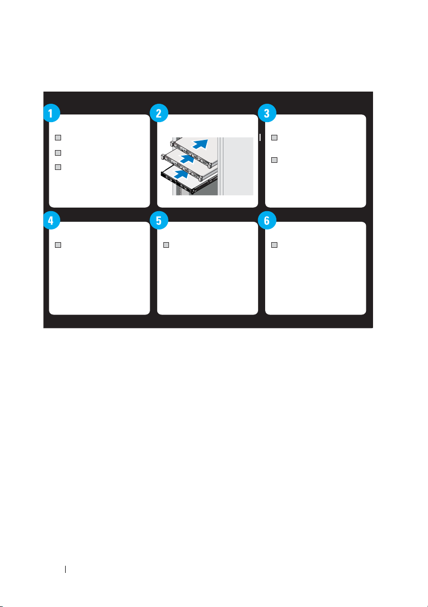
Figure 2-1. Setting Up Your PowerVault NX3500 Solution
Environment Setup
Select switch topology
Complete worksheet
Prepare management
station
Verify IPv6 address
Install software
Rack, Stack, and Cable Set up Storage
Utilize SystemInitialize File SystemConfiguration utility
Create HostGroup, Virtual
Disks, and map them together
Complete final step during
step 5
Execute PowerVault
NASCU
Complete initialization steps
in web admin interface
Create NAS volumes, CIFS
shares
Setting Up the Environment
To set up the environment:
1
Choose the topology and cable your solution.
2
Complete the NAS system setup worksheet.
3
Prepare your management station.
Choosing the Topology
Choosing the topology involves choosing the MD topology and the
switch topology.
30 Setting Up Your PowerVault NX3500 Solution
Page 31

MD Topology
Your MD array is equipped with eight ports across two controllers. You can
configure the MD array for your solution using:
• Four subnets (See Figure 2-2)
–Two for NAS
–Two for Block
• Two subnets (See Figure 2-2)
– Serves both NAS and Block
Setting Up Your PowerVault NX3500 Solution 31
Page 32

Figure 2-2. The MD Switch Topology
32 Setting Up Your PowerVault NX3500 Solution
Page 33

Choosing the Switch Topology
NOTE: The two subnets option would also be used for the MD36xxi.
The PowerVault NX3500 supports four switch topologies. The topologies are
listed in Table 2-1 with their benefits and challenges. Choose the ideal
topology for your environment and cable the solution accordingly.
Table 2-1. Switch Topologies for PowerVault NX3500 in the Non-Redundant and High
Availability Options
Topology Description High-Availability Non-Redundant
Dedicated
SAN
All-in-one
solution
This topology leverages the best
practices of the industry relating
to iSCSI and separates the SAN
and LAN/Client traffic. The client
cables are connected to a client
switch and the SAN cables are
connected to a SAN switch.
A basic topology where the SAN
and the client cables are
connected to the same switch.
Figure 2-4
(recommended)
Figure 2-6 Figure 2-7
Figure 2-5
The following settings are highly recommended on your switch:
• Spanning Tree Portfast (required)
• Flow control (required)
• Jumbo frames (9000 MTU)
NOTE: Dell PowerConnect switches need to be configured to 9216 MTU or greater
to accept frames of size 9000 MTU. Non-Dell switches may require a different MTU
configuration for similar frame sizes. For more information on MTU configuration for
non-Dell switches, see the switch-specific manual.
NOTE: Jumbo frames and flow control settings are mandatory for all ports used
solely by the PowerVault NX3500 and file access, for block usage port setting,
please refer to your array user guide for optimal performance setting.
Setting Up Your PowerVault NX3500 Solution 33
Page 34

Figure 2-3. NX3500 Node NIC Cabling
NOTE: See Figure 2-3 to connect the PowerVault NX3500 and MD ports to the
appropriate switch in the for the best practice solution in the HA option.
Best Practice Solution in the HA Option
The best practice solution is to isolate the SAN traffic from the LAN or client
traffic with redundant switches for HA. All the client cables are split between
the redundant client switches, and the SAN or internal network cables are
split between the redundant SAN switches. Peer connections are always back
to back.
NOTE: For cabling recommendation for existing MD-Series implementations that
do not have stacked switches, see “Cabling Recommendation” on page 213.
NOTE: The PowerVault NX3500 solution expects only two subnets (iSCSI ports) per
MD controller to be used by the solution. The other four ports are dedicated to
block devices.
34 Setting Up Your PowerVault NX3500 Solution
Page 35

Figure 2-4. Dedicated SAN Solution in the High Availability Option
Client Switches
SAN Switches
Controller0
Controller1
MD32xx0i
Setting Up Your PowerVault NX3500 Solution 35
Page 36

Dedicated SAN Solution in the Non-Redundant Option
The second configuration option is to isolate the SAN traffic from the client
traffic, but without redundant switches. All the client cables are connected to
the client switch and the SAN or internal network cables are connected to the
SAN switch. Peer connections are always back to back.
In this configuration, the switches become a single point of failure. It is
recommended that you separate the SAN subnets using virtual LANs.
36 Setting Up Your PowerVault NX3500 Solution
Page 37

Figure 2-5. Dedicated SAN Solution in the Non-Redundant Option
SAN Switch
Client Switch
Controller0
Controller1
MD32xx0i
Setting Up Your PowerVault NX3500 Solution 37
Page 38

All-in-One High-Availability Option
In an all-in-one high availability option, the redundant switches host both
SAN or internal and client network traffic. The SAN or internal and client
cables are split between the redundant switches. Peer connections are always
back to back. It is recommended that you separate the SAN subnets using
virtual LANs.
38 Setting Up Your PowerVault NX3500 Solution
Page 39

Figure 2-6. All-in-One High-Availability Option
Client Connections
Peer Connections
Internal Network and SAN
Controller0
Controller1
MD32xx0i
Setting Up Your PowerVault NX3500 Solution 39
Page 40

All-in-One Non-Redundant Option
In an all-in-one non redundant option, both the SAN or internal and client
cables are connected to the same switch. In this configuration, the switch is a
single point of failure. It is recommended that you separate the SAN subnets
using virtual LANs.
40 Setting Up Your PowerVault NX3500 Solution
Page 41

Figure 2-7. All-in-One Non-Redundant Option
Switch
MD32xx0i
Controller1
Controller0
Setting Up Your PowerVault NX3500 Solution 41
Page 42

Completing the NAS System Setup Worksheet
The NAS System Setup Worksheet will assist you in the overall setup and configuration of your solution.
NAS System Setup Worksheet
PowerVault NAS Configuration Utility NAS Cluster IP Allocation
Information Requested Value IP Function IPs Allocated Sample IPs Physical Connections
Storage Array Identification Subnet 1—Primary Network
MD discovery IP NAS management VIP . . . 10.10.1.200 Client
MTU Client access VIP . . . 10.10.1.100 Client
NX3500 Controller Discovery
Controller 0 MAC address Controller 1 IP . . . 10.10.1.202 Client
Controller 1 MAC address Subnet mask . . . 255.255.255.0 Client
NAS Appliance Identification Subnet 2—Internal or Private Network Group 1
NAS cluster name Internal IP a0 . . . 172.168.1.1 Internal or Peer
PowerVault NAS Configuration Utility Results
NAS controller 0 IQN Internal IP a2 . . . 172.168.1.3 Internal or Peer
NAS controller 1 IQN Internal IP a3 . . . 172.168.1.4 Internal or Peer
NOTE: Use the IQNs recorded from the
PowerVault NAS Configuration Utility (NASCU) to
complete your mappings configuration on the
MD3xx0i backend storage.
Controller 0 IP . . . 10.10.1.201 Client
Gateway . . . 10.10.1.1 Client
Internal IP a1 . . . 172.168.1.2 Internal or Peer
Subnet mask . . . 255.255.255.0 Internal or Peer
Page 43

PowerVault NAS Configuration Utility NAS Cluster IP Allocation
Environment Setup Checklist
Management station:
• Verify IPv6 enabled
• Install PowerVault NASCU
Switch topology
Determine desired switch topology from one of
the following configurations:
• Dedicated SAN solution in the high-availability
option
• Dedicated SAN solution in the high-availability
option
• All-in-one high-availability option
• All-in-one non-redundant option
Subnet 3—Internal or Private Network Group 1
Internal IP b0 . . . 172.168.2.1 Internal or Peer
Internal IP b1 . . . 172.168.2.2 Internal or Peer
Internal IP b2 . . . 172.168.2.3 Internal or Peer
Internal IP b3 . . . 172.168.2.4 Internal or Peer
Subnet mask . . . 255.255.255.0 Internal or Peer
Subnet 4—SAN Network Group 1
SANa IP 0 . . . 192.168.10.20 SAN (to Switch A)
SANa IP 1 . . . 192.168.10.21 SAN (to Switch A)
Subnet mask . . . 255.255.255.0
Subnet 5—SAN Network Group 2
SANb IP 0 . . . 192.168.11.20 SAN (to Switch B)
SANb IP 1 . . . 192.168.11.21 SAN (to Switch B)
Subnet mask . . . 255.255.255.0
Page 44

Power Vault MD Configuration
IP Function IPs Allocated Sample IPs Physical Connections
Controller 0 Port 0 IP . . . 192.168.10.100 SAN (to Switch A)
Controller 0 Port 1 IP . . . 192.168.11.100 SAN (to Switch B)
Controller 0 Port 2 IP . . . 192.168.12.100
Controller 0 Port 3 IP . . . 192.168.13.100
Controller 1 Port 0 IP . . . 192.168.10.101 SAN (to Switch A)
Controller 1 Port 1 IP . . . 192.168.11.101 SAN (to Switch B)
Controller 1 Port 2 IP . . . 192.168.12.101
Controller 1 Port 3 IP . . . 192.168.13.101
Page 45

Preparing Your Management Station
A management station is required to manage and configure the PowerVault
NX3500. The solution can be accessed using either the CLI or the Dell
PowerVault NAS Manager.
NOTE: You can log on to either the CLI or the NAS Manager at a time. It is highly
recommended that you do not attempt to log on to both the CLI and NAS Manager at
the same time.
The minimum requirements for the management station are:
•It has IPv6 enabled.
• The PowerVault NASCU is installed.
NOTE: You can install Dell PowerVault NASCU from the Dell Resource Media
Fluid File System (FluidFS) media that shipped with your solution.
• The PowerVault NX3500 is cabled appropriately, and the management
station is on the same network as the LAN or client network.
• Has either Internet Explorer or Firefox installed with JavaScript enabled.
Installing the Solution in the Rack
Your solution requires a properly grounded electrical outlet, a compatible
rack, and a rack installation kit. For information on installing the solution in
the rack, see the Setting Up Your PowerVault Network Attached Storage
Solution that shipped with your product.
Setting Up Your MD Storage Solution
This section assumes you have discovered and completed the initial configuration
(naming, assigning iSCSI, and management port IPs) of your PowerVault
MD3xx0i storage arrays in accordance with the topology you plan to use.
This section provides the steps necessary to configure the host group and
virtual disks that are required for the PowerVault NX3500 system. For
additional information regarding a task such as creating virtual disks, see the
PowerVault Modular Disk Storage Manager (MDSM) Help or the Dell
PowerVault MD3xx0i Owner’s Manual at support.dell.com/manuals.
CAUTION: Correctly preparing the PowerVault Modular Disk (MD) storage array
is critical for successfully configuring your NAS solution.
Setting Up Your PowerVault NX3500 Solution 45
Page 46

Complete the following tasks using PowerVault MDSM.
NOTE: PowerVault MDSM is available on the Resource media that shipped with
your storage array.
1
Create a disk group for each virtual disk.
2
Create a virtual disk in each disk group.
3
Create a host group.
4
Map the virtual disks to the host group.
NOTE: See the MD storage array documentation at support.dell.com/manuals.
NOTE: Additional configuration is required after completing the steps in the
PowerVault Configuration Utility. Challenge Handshake Authentication Protocol
(CHAP) must be disabled on the PowerVault MD3xx0i storage array and the storage
array must be configured for two logical SANs.
Creating Disk Groups
To cre at e dis k gro up s:
NOTE: It is recommended that you create a minimum of two disk groups. Each will
house a virtual disk dedicated to the NAS storage pool.
1
Install and launch the PowerVault MDSM software on the
management station.
2
Target the MD storage array you plan to use for your NAS storage.
See the Dell PowerVault MD3
support.dell.com/manuals
xx
0i storage arrays
.
Deployment Guide
at
3 Choose one of the following methods to start the Create Disk Group
Wizard and proceed to step 4:
– To create a disk group from unconfigured capacity in the storage array:
a
On the
b
Select
Alternatively, you can right-click
Create Disk Group
Logical
tab, select
Disk Group
Unconfigured Capacity
Create
.
Unconfigured Capacity
from the pop-up menu.
.
, and select
– To create a disk group from unassigned physical disks in the storage array:
a
On the
Physical
tab, select one or more unassigned physical disks of
the same physical disk type.
46 Setting Up Your PowerVault NX3500 Solution
Page 47

b
Select
Disk Group
Create
.
Alternatively, you can right-click the unassigned physical disks, and
select
Create Disk Group
from the pop-up menu.
– To create a secure disk group:
a
On the
Physical
tab, select one or more unassigned security capable
physical disks of the same physical disk type.
b
Select
Disk Group
Create
.
Alternatively, you can right-click the unassigned security capable
physical disks, and select
The
Introduction (Create Disk Group)
4
Click
Next
.
The
Disk Group Name and Physical Disk Selection
5
Type a name for the disk group in
NOTE: The disk group name should not exceed 30 characters.
6
Select the appropriate
Create Disk Group
window is displayed.
Disk Group Name
Physical Disk Selection
from the pop-up menu.
window is displayed.
.
choice; you can select:
For manual configuration, the Manual Physical Disk Selection window is
displayed.
•
Automatic
, see step 7
For automatic configuration, the RAID Level and Capacity window is
displayed.
•
Manual
7
Click
8
Select the appropriate RAID level in
Next
, see step 10
.
Select RAID Level
.
You can select RAID levels 1/10, 6, and 5. Depending on the RAID level
selection, the physical disks available for the selected RAID level are
displayed in the
9
In the
Select Capacity
click
Finish
Select Capacity
.
table.
table, select the relevant disk group capacity, and
Repeat the procedure for a minimum of two disk groups and then proceed
to "Creating Virtual Disks" on page 49.
Setting Up Your PowerVault NX3500 Solution 47
Page 48

If you have selected
10
In the
Manual Physical Disk Selection
RAID level in
Manual
configuration, proceed to step 10.
Select RAID Level
window, select the appropriate
.
You can select RAID levels 0, 1/10, 6, and 5. Depending on the RAID level
chosen, the physical disks available for the selected RAID level is displayed
in
Unselected Physical Disks
11
In the
Unselected Physical Disks
disks and click
NOTE: You can select multiple physical disks at the same time by holding
<Ctrl> or <Shift> and selecting additional physical disks.
Add
.
To view the capacity of the new disk group, click
12
Click
Finish
.
table.
table, select the appropriate physical
Calculate Capacity
Repeat the procedure for a minimum of two disk groups.
.
48 Setting Up Your PowerVault NX3500 Solution
Page 49

Figure 2-8. Host Group and Virtual Disks
Creating Virtual Disks
NOTE: Before creating virtual disks, organize the physical disks into disk groups
and then create a virtual disk within each disk group.
Create a minimum of two virtual disks dedicated for NAS storage. The NAS
storage capacity can be expanded up to 16 virtual disks. The number of
virtual disks must increment in pairs.
NOTE: Minimum virtual disk size required for the PowerVault NX3500 is 125 GB.
Maximum virtual disk size required for the PowerVault NX3500 is 15 TB.
Setting Up Your PowerVault NX3500 Solution 49
Page 50

Table 2-2. Creating Virtual Disks
Pai r 1
Pai r 1
Pair 2
Pai r 2
Pai r 3
Pai r 3
Item Supported Not supported
Number of VDs or
LUNs
LUN sizes 125 GB, up to 15 TB Up to 125 GB, greater than 15 TB
2, 4, 6, 8, 10, 12, 14, 16 1, 3, 5, 7, 9, 11, 13, 15
NOTE: LUN pairs
should be of the same
size.
Host group Single host group Multiple host group
VD1: 125
GB
VD2: 125
GB
VD3: 759
GB
VD4: 759
GB
VD5: 1.33
TB
VD6: 1.33
TB
VD1:125 GB
VD2: 130 GB
VD3: 759 GB
VD4: 650 GB
VD5: 1.33 TB
VD6: 1.90 TB
To create virtual disks from free capacity:
1
Start the
2
On the
Create Virtual Disk Wizard
Logical
tab, select
Free Capacity
.
from the disk group you created
in the earlier steps.
3
Select
4
Virtual Disk
The
Introduction (Create Virtual Disk)
Click
Next
.
The
Specify Capacity/Name
and then click
window is displayed.
Create
.
window is displayed.
5
Select the appropriate unit for storage capacity in
capacity of the virtual disk in
6
Enter a name for the virtual disk in
NX3500Lun0
).
50 Setting Up Your PowerVault NX3500 Solution
Units
New Virtual Disk Capacity
Virtual Disk Name (
and enter the
.
for example,
Page 51

NOTE: The virtual disk name should not exceed 30 characters.
7
In
Advanced Virtual Disk Parameters
•
Use Recommended Settings
•
Customize Settings
8
Click
Next
.
9
In the
Customize Advanced Virtual Disk Parameters
, select one of the following options:
window, select the
appropriate Virtual Disk I/O characteristics type.
10
Select one of the following options:
•
File system (typical)
•
Database
•
Multimedia
•
Custom
NOTE: If you select Custom, you must select an appropriate segment size and
preferred RAID controller module ownership. For more information, see the
MD storage array documentation at support.dell.com/manuals.
11
Click
Finish
.
The virtual disks are created.
Creating a Host Group
To create a host group:
1
Launch the PowerVault MDSM and target the MD storage array you plan
to use for your NAS storage.
2
Select the
3
In the
4
Perform one of the following actions:
• Select
• Right-click the storage array or the
5
Type the name of the new host group in
(for example,
Mappings
To po l og y
Mappings
Host Group
NX3500
tab.
pane, select the storage array or the
and then
Define Host Group
Default Group,
from the pop-up menu.
Enter New Host Group Name
).
Default Group
.
and select
.
Define
NOTE: Host group name must have alphanumeric characters.
Setting Up Your PowerVault NX3500 Solution 51
Page 52

NOTE: Since the controllers are not configured yet, no hosts are available at
this time. No host other than the NX3500 controllers should be added to this
host group.
6
Click OK.
The host group is added to the storage array.
Creating Host-to-Virtual Disk Mappings
To create host-to-virtual disk mappings:
1
Launch PowerVault MDSM and target the MD storage array you plan to
use for your NAS storage.
2
In the
To po l og y
you created in the previous steps.
3
In the tool bar, select
The
Default Additional Mapping
4
In
Host group or host
All defined hosts, host groups, and the default group appear in the list.
5
In the
Logical Unit Number
0 through 255.
6
Select the virtual disk to be mapped in the virtual disk area.
The virtual disk area lists the names and capacity of the virtual disks that
are available for mapping, based on the selected host group or selected
host. Only select the virtual disks that were created specifically to be used
by the PowerVault NX3500. You must select an even number of virtual
disks, up to 16.
pane, expand
Default Group
and select the host group
MappingsDefineAdditional Mapping
window is displayed.
, select the host group you created in the previous steps.
field, select a LUN. The supported LUNs are
.
7
Click
Add
.
NOTE: The Add button is inactive until a host group or host, LUN, and virtual
disk are selected.
8
To define additional mappings, repeat step 4 through step 7.
NOTE: After a virtual disk has been mapped, it is no longer available in the
virtual disk area.
9
Click
Close
.
52 Setting Up Your PowerVault NX3500 Solution
Page 53

The mappings are saved. The Top ol o gy pane and the Defined Mappings
pane in the Mappings tab are updated to reflect the mappings.
Running the PowerVault NASCU
The PowerVault NAS Configuration Utility (NASCU) walks you through the
steps necessary to set up the network configuration and pair the PowerVault
NX3500 controllers together. It also starts the process of pairing the system to
the PowerVault MD3xx0i storage appliance. It is recommended that you
determine your network configuration and IP address allocation for your NAS
controllers before executing this utility. See “Completing the NAS System
Setup Worksheet” on page 42.
Before running the PowerVault NASCU, ensure that:
• The PowerVault NASCU is installed and executed from a management
station that has IPv6 enabled. The utility connects to and configures your
controllers through the local link Ipv6 address. Ipv6 can be disabled, but
only after the installation and configuration is complete.
• The management station is connected to the same switch as the client
connections on your NAS controllers (see Table 2-1).
NOTE: Use the PowerVault NASCU only for initial configuration. After the PowerVault
NX3500 is configured use the NAS Manager to make changes to the configuration.
Installing the PowerVault NASCU
NOTE: Do not attempt to use the PowerVault NASCU to reconfigure an already
clustered PowerVault NX3500 solution.
For Windows-based management stations:
1
Insert the
If
autorun
after a few moments.
2
If
autorun
3
If
autorun
installer, open an explorer window and navigate to the optical drive where
the
PowerVault NX3500 Resource Media
is enabled on your system, the installer automatically launches
is enabled, proceed to step 5.
is disabled, or if
PowerVault NX3500 Resource Media
autorun
Setting Up Your PowerVault NX3500 Solution 53
does not automatically launch the
into the optical drive.
is located.
Page 54

4
Open
StartHere.htm
5
Follow the prompts in the installer to complete the installation.
For Linux-based admin stations:
Graphical Installation
1
Insert the
2
Point the file-system explorer to the mounted optical drive.
3
Run
This launches an internet browser.
4
Follow the prompts in the installer to complete the installation.
Command-Line Installation
1
Insert the
2
Open a terminal window and change directories (cd) to the optical drive
(For example,
3
Change directories to the
4
Identify the build of operating system being used (32-bit or 64-bit) and
change directory into either the
Linux_i386/VM/ (32-bit)
5
Run the installer located in this folder by calling
installer-linux-<build_type>.bin
6
Follow the steps in the installer to complete the installation.
PowerVault NX3500 Resource Media
StartHere.htm
PowerVault NX3500 Resource Media
.
.
cd /media/disk/media/cdrom
InstData
folder.
folder.
Linux_amd64/VM/ (64-bit)
.
into the optical drive.
into the optical drive.
).
sh ./pv-nas-config-utility-
or
Launching the PowerVault NASCU
For Windows-based operating systems:
1
Access the Windows desktop and double-click the
Configuration Utility
navigate to
2
Click on
For Linux-based operating systems:
1
Execute the
2
Ensure that the currently logged-on terminal user is
54 Setting Up Your PowerVault NX3500 Solution
All ProgramsDellPowerVault NAS
PowerVault NX3500 Configuration Utility
PowerVault NASCU
icon, or access the Windows start menu and
from a terminal prompt.
PowerVault NX3500
.
.
root
.
Page 55

To change the user to
a
At the prompt, type su
b
Navigate to the root home folder by typing
c
Execute the
Config-Utility
root
:
and enter the root password at the prompt.
PowerVault NASCU
.
by typing
cd ~/
.
/bin/sh./Dell-PV-NAS-
The welcome screen is displayed.
The actual configuration is deferred until all settings are confirmed in the
Configuration Summary
CAUTION: Use this utility only to configure two unconfigured controllers. Do not
attempt to use this utility on fully configured or clustered PowerVault NX3500 or to
reconfigure IP addresses. This utility does not check for duplicate IPs or null entries.
The
Storage Array Identification and Configuration
screen.
window is displayed.
3
Ty pe in th e
4
Click
MD Discovery IP
Next.
address, the
Setting Up Your PowerVault NX3500 Solution 55
Subnet Mask,
and the MTU size.
Page 56

MD Discovery IP and subnet mask:
This is one of the iSCSI Host port IPs
configured on the MD array controller iSCSI ports. You can access this
information from the MDSM. This IP address is used by the PowerVault
NASCU to establish communication with the MD storage array
.
SAN MTU size:
This is the MTU setting for the SAN network. Using
jumbo frames on the SAN network (MTU: 9000) is mandatory for new
installations. For an existing MD setup, it is highly recommended that you
use jumbo frames for optimal performance.
The
NAS Controller Discovery
NOTE: Dell PowerConnect switches must be configured to 9216 MTU or greater
to accept frames of size 9000 MTU. Non-Dell switches may require a different
MTU configuration for similar frame sizes. For more information on MTU
configuration for non-Dell switches, see the switch-specific documentation.
window is displayed.
5
Type in the Controller MAC addresses.
These are the string of numbers under the EMB NIC1 MAC Address on
the Service Tag slide out tag.
56 Setting Up Your PowerVault NX3500 Solution
Page 57

Controller MAC addresses:
These are used to establish communication
with the PowerVault NX3500 controllers and perform initial configuration.
This can be found on the System Identification slide out tab located
underneath the front bezel of the controller. The back of the tab lists the
“Embedded NIC 1 MAC address”. The connect button starts the co-click.
6
Click
Connect
NOTE: The slide out tab has two MAC addresses. Ensure that you enter the
embedded NIC Address and not the iDRAC address.
7
Enter the name used to identify the NAS cluster within the web
to check if NAS controllers are connected and click
administration interface.
8
Click
Next
.
The cluster name should be only alphanumeric characters with no spaces
or special characters other than dashes.
The
Primary Network Configuration
window is displayed.
Next
.
9
Type in the required parameters and click
Setting Up Your PowerVault NX3500 Solution 57
Next
.
Page 58

IP address descriptions are as follows:
•
Client Access VIP
: This is the IP address used to access CIFS and
NFS shares.
•
NAS Management VIP
: This is the IP address used to access the NAS
Manager and command line administration interfaces.
NOTE: Make a note of the NAS Management VIP address for use at a
later stage.
•
Controller IPs
: Private maintenance IP addresses for each controller
and should not be accessed by clients directly.
•
Gateway IP Address
: This is the IP address through which a system on
the network can be reached at all times, such as a domain controller.
The Gateway IP address should always be accessible to the PowerVault
NX3500 controllers.
The
Internal Network Configuration
window is displayed.
58 Setting Up Your PowerVault NX3500 Solution
Page 59

10
Type in the required parameters in the
window and click
Internal IPs
Next.
: These are used for internal communication between the
Internal Network Configuration
controller pair. IP addresses specified must be grouped in two different
subnets and be completely isolated from any other system on the network.
The PowerVault NASCU requests for these IP addresses to ensure that
there are no IP address clashes with other systems on your network.
The
SAN Network Configuration
window is displayed.
11
Type in the required parameters and click
SAN IPs
: These are used for iSCSI communication with the backend
storage device (PowerVault MD3
same subnets configured on the MD3
established with the MD3
xx
0i storage array over the two subnets specified.
Setting Up Your PowerVault NX3500 Solution 59
Next
.
xx
0i). As a result, these IPs must be on the
xx
0i storage array. iSCSI sessions are
Page 60

NOTE: The MD storage array best practices recommend different subnets to
be configured on each port of the MD controllers. For MD device such as the
MD3200i with four ethernet ports per controller, the NAS cluster establishes
iSCSI connections on two of the ports. The other two ports can be used to
provision block storage to other iSCSI clients.
The
Configuration Summary
window is displayed.
All settings are applied to your controllers after this point. Listed below is a
checklist of items to review:
• Ensure no duplicate IP addresses are present
• Check that IP groups are in the same subnet as required
• NAS cluster name follows expected naming convention
• SAN MTU setting matches MTU configuration of the switch
connecting the NAS controllers to the backend MD3
x
x0i storage
device
12
Click
Next
on the
Configuration Summary
window.
60 Setting Up Your PowerVault NX3500 Solution
Page 61

The
Configuration Results
window is displayed.
Upon successful configuration, the PowerVault NASCU presents you with the
NAS controller IQNs required to complete the pairing to the backend MD
storage device. Copy the IQNs for both controllers to a notepad, which is
entered into MDSM.
NOTE: Do not copy trailing white spaces along with the IQN, as this is interpreted as
part of the IQN and causes an iSCSI login failure at a later part in the configuration.
NOTE: MDSM refers to IQNs as host port identifiers.
If there is an error, see "NAS Container Security Violation" on page 189.
When you click Next, the NAS Manager is launched in your default web
browser. The Configuration Wizard is displayed and it guides you through
the steps to configure and start the NAS service. If it does not open, follow
the procedure in "Accessing the NAS Manager Web Interface" on page 64 to
access the wizard.
Setting Up Your PowerVault NX3500 Solution 61
Page 62

NOTE: Before running the NAS Manager Configuration Wizard, create two hosts
(one per controller) in the host group you created earlier. Enter the IQNs provided in
the configuration results into the Host Port Identifier field for each controller. See
"Define Two Hosts" on page 62. After defining hosts, proceed to the NAS Manager
Configuration Wizard.
Define Two Hosts
Define the hosts as follows:
1
From the PowerVault MDSM for the array you plan to use for your NAS
storage, perform one of the following actions:
• Select
• Select the
• Select the
2
In
Host name
3
Select
identifier
PowerVault NASCU and enter a user label
click
Mappings
(See “Creating a Host Group” on page 51.) in the
select
Define Host
The
Specify Host Name
, enter a host name (for example,
NOTE: The host name should be alphanumeric characters with the only
special character "-".
Add by creating a new host port identifier
and then
Setup
tab, and click
Mappings
Define Host
.
Manually Define Hosts
tab. Right-click the
Host Group
from the pop-up menu.
window is displayed.
.
that you created
To po lo g y
NX3500-Controller-0
. In the
New host port
field, enter the IQN from the configuration results of the
for the host port identifier and
Add
.
pane, and
).
NOTE: The user label cannot be the same as the host name, it should be
based off the host name. For example: NX3500-Controller-0-IQN.
4
Click
Next
.
Specify Host Type
The
5
In
Host
type, select
The
Host Group Question
6
In this window, select
window is displayed.
Linux
as the operating system for the host.
window is displayed.
Ye s
.
This host shares access to the same virtual disks with other hosts.
7
Click
Next
.
62 Setting Up Your PowerVault NX3500 Solution
Page 63

The
Specify Host Group
8
Select the host group you created (see “Creating a Host Group” on
page 51), and click
The
Preview
9
Click
Proceed to the
window is displayed.
Finish and repeat
NAS Manager Configuration Wizard
window is displayed.
Next
.
step 1 to step 9 for Controller1.
that was launched in
your web browser.
Figure 2-9. Hosts in Host Group
Setting Up Your PowerVault NX3500 Solution 63
Page 64

NAS Manager Configuration Wizard
The NAS Manager Configuration Wizard helps complete the PowerVault
NX3500 configuration and integrate the solution into the environment. It lets
you set up the DNS, time management, user identification, and
authentication parameters, and monitoring options as well as formatting and
starting the file system.
You can leave the wizard at any time by selecting another page from the
Navigation pane. Every page in the Configuration Wizard can also be
accessed from the Navigation pane. This means that you can modify the
system's configuration parameters directly, by accessing the appropriate page
from the Navigation pane, without having to run the entire wizard.
Accessing the NAS Manager Web Interface
To access the NAS Manager:
1
Access the PowerVault NAS Manager web interface using the NAS
Management VIP address you specified in the PowerVault NASCU.
The
Security Alert
NOTE: The Security Alert window is displayed after you install the
PowerVault NX3500 system, or after upgrading the system. Clicking Yes
enables the current session. Clicking View Certificate, as explained in the
following step, enables all future sessions.
2
Click
View Certificate
The
Certificate
window is displayed.
.
window is displayed.
3
Click the
The
4
Click
The
5
Verif y th at
certificate
The
6
Click
A
Security Warning
Install Certificate
Welco me
Next
window of the
.
Certificate Store
button.
Certificate Import Wizard
window is displayed.
Automatically select the certificate store based on the type of
is selected and click
Next
.
Completing the Certificate Import Wizard
Finish
.
window is displayed.
64 Setting Up Your PowerVault NX3500 Solution
is displayed.
window is displayed.
Page 65

7
Click
Yes
.
A
Certificate Import Wizard
successful
8
Click OK.
9
Click
OK
in the certificate window.
10
Access the NAS Manager.
The
PowerVault License file
NOTE: This window is displayed only if the license has not been installed.
11
Browse to the
The
PowerVault NAS Manager Login
12
Typ e t he
username
NOTE: Use admin as the username. The default password is Stor@ge!. You
have the option of changing the password later.
".
License file
and
message is displayed: "
window is displayed.
and click
Install
window is displayed.
password
and click
The PowerVault NAS Manager is displayed with the
Wizard
page open.
NOTE: If the Start Configuration page does not open automatically, click System
ManagementMaintenanceStart Configuration Wizard.
.
Log in
The import was
.
Start Configuration
Setting Up Your PowerVault NX3500 Solution 65
Page 66

PowerVault NAS Manager Configuration Wizard
Table 2-3 describes the options available on the PowerVault NAS Manager
Configuration Wizard.
Table 2-3. The PowerVault NAS Manager Configuration Wizard Options
Option Description
Solution Integration
DNS Configuration
Time Configuration
Monitoring
Email (SMTP)
Configuration
SNMP Configuration
System Function
Format File Syst e m
System Stop/Start
Change Passwords Enables you to change the admin and CIFS
System and Users Identity
System Identity Enables you to configure the system name and the
CIFS Protocol
Configuration
Identity Management
Database
Cross Protocol:
to UNIX User Mapping
Using Your System
Windows
Enables you to configure DNS parameters.
Enables you to configure time zone parameters
and synchronize the time zone with NTP servers.
Enables you to configure the system’s alerting
mechanism using email.
Enables you to configure the system’s SNMP
access and trap parameters.
Enables you to format the file system.
Enables you to start the file system.
Administrator’s password.
Active Directory domain it belongs to.
Enables you to allow file access using the CIFS
protocol and specify how CIFS users are
authenticated.
Enables you to configure additional identity
databases, such as NIS or LDAP.
Enables you to configure user identity
interoperability between Active Directory and
UNIX identity databases.
66 Setting Up Your PowerVault NX3500 Solution
Page 67

Table 2-3. The PowerVault NAS Manager Configuration Wizard Options
Option Description
NAS Volumes
Configuration
CIFS Shares Enables you to configure CIFS shares.
NFS Exports Enables you to configure NFS exports.
Enables you to configure NAS volumes.
(continued)
Setting Up Your PowerVault NX3500 Solution 67
Page 68

68 Setting Up Your PowerVault NX3500 Solution
Page 69

3
Accessing the Dell PowerVault NAS Manager
The NAS Manager is a web-based user interface that enables you to configure
and monitor your PowerVault NX3500 storage system.
Browser Requirements
•Firefox 3.6
• Internet Explorer 7, 8
The NAS Manager can be displayed at resolutions of 1024 x 768 pixels or
above. It is recommended to display the web interface at High Color, 16-bit
resolution. Also, disable any type of pop-up blocker application while using
the web interface as it may cause unpredictable behavior.
NOTE: It is highly recommended that JavaScript be enabled in your browser for
NAS Manager to function properly.
Accessing the Dell PowerVault NAS Manager 69
Page 70

NAS Manager Overview
1 23 456
The NAS Manager web interface comprises of the Admin tabs, Admin tree,
Pages, Action bar, Search bar, and Toolbar.
Figure 3-1. NAS Manager Web Interface
1 Admin tree 4 Action bar
2 Admin tabs 5 Search bar
3 Page 6 Toolbar
70 Accessing the Dell PowerVault NAS Manager
Page 71

Action Bar
The Action bar, consists of additional functionality relevant to the current
page displayed. For more information on the menus, see the Online Help.
Admin Tabs
The Admin tabs divide the administration tasks into functional groups.
When you select a different tab, the options displayed in the Administration
tree changes.
For more information on the Admin tabs and their functionality, see
the Online Help.
Admin Tree
The Admin tree, located above the Admin tabs in the left pane, shows the
available functionality and changes depending on the Admin tab selected.
The Admin tree divides the functionality into groups and subgroups. This
enables you to easily find the task you need to perform.
Tool ba r
The NAS Manager toolbar, located on the upper right side of the page,
displays the following options.
Table 3-1. The NAS Manager Toolbar Options
Option Description
About Selecting this opens the About screen with the current version
information.
Help Selecting this opens the online help in the section most relevant
to the currently displayed page.
Logout Selecting this enables you to exit the NAS Manager.
Page
The Page displays the function currently selected in the Admin tree or Action
bar. You can enter information, make changes, or simply view the current
status or configuration settings.
Accessing the Dell PowerVault NAS Manager 71
Page 72

NOTE: The functionality and actions in NAS Manager are dynamic and are
available as determined by the permissions allocated to each user.
NOTE: You can log on to either the CLI or the NAS Manager at a time. It is highly
recommended that you do not attempt to log on to both the CLI and NAS Manager at
the same time.
Search Bar
When a page contains a table of items, the Search bar is displayed and allows
you to quickly find the relevant lines.
Each table displays up to 50 lines at a time. If more than 50 lines are available,
they are split into multiple pages with 50 lines per page. You can move from
one page to another by using the relevant buttons in the Search bar.
You can change the order a table is sorted by clicking on the column title.
Click once to change the sorting order to ascending and click again to change
the sorting order to descending.
The NAS Manager Search bar, located beside the page title, displays the
following items.
Table 3-2. The NAS Manager Search Bar Options
Option Icon
Description
Search filter field N/A Enter the string you want to use in the
Search button N/A Press this button after entering a search
Go to first page |< Press this button to go to the first page of
Go to previous page < Press this button to go to the previous page of
Current page number N/A This field shows the current page number.
Go to next page > Press this button to go to the next page of data.
Go to last page >| Press this button to go to the last page of
Description
search. All text columns in the table are then
searched.
string to filter the table.
data.
data.
You can modify this field and press <Enter>
to quickly switch to a specific page.
data.
72 Accessing the Dell PowerVault NAS Manager
Page 73

4
Monitoring PowerVault NX3500
NOTE: The information in this chapter refers to file management using the Dell
PowerVault NAS Manager. Block management and monitoring is done using Dell
PowerVault Modular Disk Storage Management (MDSM).
You can monitor the status of the Dell PowerVault NX3500 NAS clustered
system using the Monitor tab in the NAS Manager. Here, you can view the
overall status of the system on the Dashboard page, see the quotas usage
report, and receive remote replication job status reports.
To access the monitoring pages, click the Monitor tab in the Admin tabs. By
default, the Dashboard page is displayed.
Table 4-1. Monitor Tab Options
Field Description
Overview
Dashboard
Network Performance
Load Balancing
Over time
Client Connections
CIFS Connections
Hardware
System Validation
Provides a single glance monitoring of the system.
Allows you to see network throughput for read and writes
in IOPS and MBps for last day, week, month, and year.
Allows you to see processor load, CIFS connections,
read and write throughput for each controller for last
day, week, month, and year.
Allows you to see load balancing of client connections
by protocol and controller. Lets you set the migration
policy for each protocol.
Allows you to see a list of CIFS connections.
Allows you to see the diagnostic test result of each of
the system components.
Monitoring PowerVault NX3500 73
Page 74

Table 4-1. Monitor Tab Options
Field Description
Component Status
Capacity
Space Utilization
Quota Usage
Replication
NAS Replication
NDMP
NDMP Active Jobs
(continued)
Allows you to see the connectivity, power, and hardware
status of each controller.
Allows you to see free space, non-snapshot used space,
and snapshot used space for each NAS volume for last
day, last week, last month, and last year.
Allows you to see the quota usage for each NAS volume
for users and groups.
Allows you to see a list of NAS replication events.
Allows you to see a list of NDMP active jobs.
Dashboard
The Dashboard page is displayed by default when you click the Monitor tab.
It shows the status of the entire system in a single view. The Dashboard page
includes five real-time and short-term sections:
• Status
• Capacity
• Current Performance
• Recent Performance
• Load Balancing
NOTE: The information in the screen is refreshed automatically every few seconds.
Status
The Status section displays the system status and a list of hardware
components. Each hardware component type displays the total number of
components and the number of problematic components. The list includes
controllers and the Backup Power Supply (BPS). The power section of the
controllers refers to the BPS.
74 Monitoring PowerVault NX3500
Page 75

Table 4-2. Status Section Options
Item Status Description
Overall State On The file system is started.
Off The file system is stopped.
Stopping The file system is stopping.
Service Status Full Service The system is fully operational and can be
accessed by all clients. The system is in
mirroring mode, that is, the write-back
cache is protected by peer controller.
Partial Service The system may provide partial services
to all clients.
Full Service (journal) The system is fully operational and can be
accessed by all clients. The system is in
journaling mode, that is, the write-back
cache is protected and all the data is
written directly to the disk rather than
stored in the cache in order to preserve
data integrity.
No Service The system does not provide service to
any clients.
Fault The system has a problem providing
service. The system may recover
automatically within several minutes
depending on the fault.
Servers Status All Optimal All the indicators of controllers' health are
optimal.
Not Optimal Some indication of a problem exists, but
this does not prevent service to clients.
For example, this may result from powerloss to a power supply, or a network
interface disconnection.
Some Down One controller is not responding, but the
system provides service in a degraded
mode. The server might recover
automatically, depending on the reason.
Monitoring PowerVault NX3500 75
Page 76

Table 4-2. Status Section Options
Item Status Description
Some Detached One controller is detached, but the
Fault Peer controllers are unable to provide
(continued)
system provides service in a degraded
mode. The controller will require manual
intervention to recover (re-attach).
service, and therefore the system does not
provide service. This can happen if
controllers are down or have lost access to
the storage sub system.
Capacity
Table 4-3. Capacity Section Options
Color Title Description
Green Free Space The space allocated to NAS
volumes but not yet in use.
Light Blue Used space non-snapshot The space allocated to NAS
volumes and used for live data.
Purple Used space snapshot The space allocated to NAS
volumes and used for snapshots.
Gray Unallocated The space, available on the LUNs,
which is not allocated to any NAS
volume.
Current Performance
The Current Performance section displays the current network throughput.
The current network throughput includes data read-write throughput (MBps)
and the number of read-write operations per second, per protocol.
NOTE: To display the Network Performance page, click the Current Performance title.
76 Monitoring PowerVault NX3500
Page 77

Table 4-4. Recent Performance Indicators
Color * Operation Description
Dark Purple Read Data read from the system
(MBps).
Light Blue Write Data written to the system
(MBps).
* See Table 4-5.
Load Balancing
The Load Balancing section displays a table with real-time information
about the PowerVault NX3500 status, processor utilization, and the number
of connections for each controller. Table 4-5 provides a broad view of the
system's load balancing.
NOTE: To display the Load Balancing page from the Dashboard, click the Load
Balancing title.
Table 4-5. Processor Utilization Indicators
Color Description
Light Green Indicates the percentage of the processor in a controller that is
busy.
Blue Indicates the percentage of the processor in a controller that is
idle.
Monitoring PowerVault NX3500 77
Page 78

Network Performance
The Network Performance page displays PowerVault NX3500 performance
over time. This page contains four tabs, each provides a different period. For
example, last day, last week, last month, and last year.
Table 4-6. Network Performance Indicators
Color Protocol Description
Green CIFS Data read or written using the CIFS protocol (MBps)
Blue NFS Data read or written using the NFS protocol (MBps)
Purple Replication Data read or written by NAS replication (MBps)
Yellow NDMP Data read or written by backup and/or restore
Magenta Network Network and protocol overhead, for example,
metadata operations (MBps)
Client Network Throughput—Read or Write
At the top of the screen there are two graphs, Client Network Throughput—
Read and Client Network Throughput—Write. The graphs display
throughput information (read and write) by protocol.
Operations Per Second
The lower left side of the screen shows the operations per second (OPS)
graph. The graph displays OPS information per operation.
Table 4-7. OPS Information Per Operation
Color Operation Description
Green Read The number of read operations per second.
Blue Write The number of write operations per second.
Magenta Other The number of meta-data operations per second.
Network Aggregated Throughput
The lower right side of the screen shows the Network Aggregated Throughput
graph. The graph displays total network throughput by network.
78 Monitoring PowerVault NX3500
Page 79

Load Balancing
Over Time
The Load Balancing Over Time page displays the balance in load between
PowerVault NX3500 controllers over time. The screen includes four tabs, each
tab presents a different period, for example, last day, last week, last month,
and last year.
CPU Load
The top left side of the screen displays the processor load graph. This graph
displays the average processor utilization in percentage for each of the
selected controllers.
CIFS Connections
The top right side of the screen displays the CIFS Connections graph. The
graph displays the number of active connections for each of the selected
controllers. Only CIFS connections appear in the graph (NFS clients are not
connection oriented).
Throughput—Read or Write
The bottom of the screen displays two graphs:
•Throughput—Read
•Throughput—Write
The graphs display the combined actual throughput, excluding overhead
(read and write) for each of the selected controllers.
Client Connections
The Client Connections page enables the following:
• Display the distribution of clients between controllers.
• Manually migrate specific clients from one controller to another.
• Set the policy for automatic client migration.
Monitoring PowerVault NX3500 79
Page 80

Displaying Client Distribution
The client's distribution page displays only clients that belong to the same
subnet as the system (local clients). Clients that access the system through a
router (or layer 3 switches) are not displayed in this page; instead, the router
is displayed.
By default, the Clients tab displays a list of all the client connections. You can
narrow the list down and display connections for specific Protocol, Controller,
and Network.
The client connections table provides the following information.
Table 4-8. Client Connections Page
Field Description
Client/router IP The IP address of the client or router accessing the system.
Access using IP The IP address used to access the system.
Assigned interface The controller and network interface which were allocated for
this client or router (either automatically by the system or
manually by an administrator).
Current interface The controller and network interface currently assigned to
this client or router. The current interface can be different
from the assigned interface after automatic connection failover. Depending on the Migration Policy, a connection that
was migrated from its assigned controller to another
controller, can remain on that controller. In such an event, the
current interface is different from the assigned interface.
Protocol The protocol that the client connection uses: CIFS, NFS, or
Other. PowerVault NX3500 identifies the clients accessing
with a recognized protocol, CIFS, or NFS and displays the
actual protocol. For other local clients, for example, routers,
the system displays the value 'Other' as the protocol.
80 Monitoring PowerVault NX3500
Page 81

Usage Considerations
Migrating Clients to Another Controller
If there is an imbalance in the network load, the system can rebalance the
load by migrating clients between controllers, either automatically or
manually. Choose whether the clients or routers in the list may be migrated to
other controllers.
Select the connections you want to migrate from the list and click Assign
Interface. The Assign Interface page displays, and lists the selected
connections for approval.
Choose the controller you want to migrate the selected clients to. You can
either choose a specific controller as the target or choose Assigned Controller.
• To migrate all the selected clients to a specific controller, choose a specific
controller from the list.
• To migrate all the selected clients back to their original controllers after a
failed controller is revived, choose the Assigned Controller. Each client can
have a different assigned controller.
You can either let the system select the target interface on the controller, or
choose a specific one.
NOTE: This operation will disconnect CIFS connections if they are migrated to a
different controller.
• To enable automatic rebalance, select
other controllers when rebalancing the network load
• To keep the selected clients assigned controller permanent (except during
fail-over) clear
rebalancing the network load
Allow these clients to migrate to other controllers when
.
Allow these clients to migrate to
.
Setting the Migration Policy
In case of a controller failure, the system automatically migrates each
connection from the failed controller to another controller to allow clients to
continue their work. This causes disconnections to CIFS clients. When the
failed controller revives, the system can rebalance the load by migrating
clients back to the revived controller automatically. This operation is called
fail-back.
Monitoring PowerVault NX3500 81
Page 82

Clients that use NFS are stateless and are not affected during fail-back.
Clients that use connection-based protocols (CIFS), may be disconnected
during fail-back. To optimize the fail-back operation, the system provides you
with the following policies for migration on recovery, which affect the loadbalance and disconnections:
• Migrate Immediately—Always keep the system well balanced, at the cost
of possibly disconnecting CIFS clients during work time.
• Migrate Automatically— Always keep the system well balanced if the
controller failure is very short, at the cost of disconnecting CIFS clients.
This option causes the system to remain unbalanced for a period of several
days, if the failure remains for long time.
This mode overcomes short controller failures because clients have not
created new material during the short time failure. Therefore, the best
practice is to rebalance them as soon as possible.
If the failure is longer than 10 minutes, the system remains unbalanced
until you rebalance it manually.
• Migrate Manually— Never migrates clients automatically. This requires
manual intervention to rebalance the system.
If the system requires manual intervention to rebalance it after fail-over,
the system sends an appropriate email message to the administrator.
You can configure the fail-back policy, as described above, per protocol and
LAN or client network.
CIFS Connections
The CIFS Connections page enables you to monitor current CIFS
connections. To manage CIFS connections, choose MonitorLoad
BalancingCIFS Connections. The CIFS Connection page is displayed.
82 Monitoring PowerVault NX3500
Page 83

Table 4-9. CIFS Connections
Field Description
Process ID The Client Connection ID.
User Name The domain and name of the user.
Client The client computer name.
Controller Name The controller that the client is connected to.
Login Time The connection time.
To disconnect a client from the CIFS protocol:
1
Select the check box beside the specific client.
2
Click
Disconnect
in the
Action
bar.
To disconnect all the connections for a specific controller:
1
Select the check box adjacent to the controller name.
2
Click
3
Click
Disconnect
Refresh
in the
Action
bar.
to update the information displayed.
Hardware
The System Validation page shows the current status of all components in
the PowerVault NX3500. It provides information about processors,
monitoring availability, NICs, IPMI, Ethernet bandwidth, BPS monitoring,
cabling connectivity, temperatures, memory, network statistics, and
Ethernet connectivity.
The Component Status page displays the current status of the PowerVault
NX3500. It provides information about status, internal hardware,
connectivity, and power for the two controllers.
Monitoring PowerVault NX3500 83
Page 84

Component Status
Viewing Detailed Status
To view additional details on the status of a specific controller, click the
controller whose information you want to view. The Controller Status page is
displayed. The following information is displayed for each controller.
Table 4-10. Controller Status Page
Field Description
Controller Displays the name of the selected controller.
Local IPMI Status Displays the status of the IPMI on the selected
controller.
Connectivity Status to Peer
IPMI
Number of CPUs Displays the total number of processors in the
Number of Ethernet NICs Displays the total number of network ports in the
UPS Battery [%] Displays the percentage of power stored in the BPS.
UPS Remaining Battery Time
[minutes]
Indicates whether the IPMI on the peer controller
is accessible and responsive.
controller, and indicates if any of the processors are
overheated.
NOTE: The total number of processors indicate the
single processor with four cores.
controller, and indicates if any ports do not have links.
Displays the time in minutes that the BPS can
support the system.
84 Monitoring PowerVault NX3500
Page 85

Capacity
Space Utilization
The Space Utilization page displays the current space utilization and space
utilization over time. The screen shows five tabs, including the current and
four over time tabs: last day, last week, last month, and last year.
Current Tab
The Current tab displays a list of NAS volumes.
Table 4-11. Current Tab
Field Description
NAS Volume The name of the NAS volume.
Allocated Space The space allocated for this NAS volume (GB).
Free Space Space allocated to NAS volumes but not yet in use
(GB).
Used Space Space allocated to NAS volumes and is in use (GB).
%Used by snapshot Percentage of used space assigned to snapshots.
The last field of the NAS volume row displays a graph of the space utilization
for each one of the volumes.
The end of the table provides a summary (total) row with the total for
Allocated Space, Used Space, and Free Space.
The last row displays the total unallocated space. This is the space available
for creation of new NAS volumes.
Table 4-12. NAS Volume
Color Legend Description
Blue Used space
non-snapshot
Purple Used space
snapshots
Green Free space Space allocated to the NAS volume but not yet in use.
Space allocated to the NAS volume and used for live
data.
Space allocated to the NAS volume and used for
snapshots.
Monitoring PowerVault NX3500 85
Page 86

Quota Usage
The Quota Usage page displays the quotas and usage of all users including
users for which no quota has been defined. It includes users that have been
removed from the system but still have usage.
To display the quotas usage, choose MonitorCapacityQuota Usage.
The Quota Usage page is displayed.
Replication
Active Remote Replication Jobs
The Active Remote Replication Jobs page enables you to monitor all active
tasks (jobs) in the cluster. In addition, you can view the list of job histories (all
non-active jobs that were executed on the cluster since the last installation).
To monitor and view jobs, choose MonitorNAS Replication.
The Active Remote Replication Jobs page is displayed.
Remote Replication Report
The Remote Replication Report page enables you to display all non-active
jobs that were executed on the cluster since the last installation.
To display the Remote Replication Report page, choose MonitorNAS
Replication.
86 Monitoring PowerVault NX3500
Page 87

5
Monitoring PowerVault NX3500 Events
You can monitor your Dell PowerVault NX3500 system by detecting normal
and abnormal events within your system using the Event Viewer utility. You
can use predefined queries to search for specific types of events such as
Current, Major-Critical, and Remote Replication.
To op en t he Event Viewer tab:
1
Click
Event Viewer
2
Choose an existing query, or create a query by clicking
The following are the default (predefined) queries:
•
Current:
•
Major-Critical:
the system.
•
Remote Replication:
When you click on a specific entry (row) in the Event Viewer page, an Event
Details window opens providing you with more information about this entry.
Here are the possible fields which could appear in a query.
Displays the most recent events.
in the
Admin
tabs to access the
Displays the events most crucial to the functioning of
Displays events related to backup of data.
Event Viewer
Filter
in the
page.
Action
bar.
Monitoring PowerVault NX3500 Events 87
Page 88

Table 5-1. Event Viewer
Field Description
Event ID The identification of event.
Severity The level of importance of the event.
Date The date when the event occurred.
Microseconds The time in microseconds the event
occurred after service start.
Subsystem The name of the subsystem on which the
event occurred.
Module The module which is involved in the event.
PID The process ID.
Cleared The event clear flag.
Context The context of the event.
Description A brief description about the event.
Event Search
The Event Viewer search utility enables you to find specific information
about your PowerVault NX3500 in the system log. For example, if you want to
debug a certain component and would like to view all the messages regarding
that component. Other examples include searching for a string, or finding out
if a certain service is currently activated.
To se arch the Event Viewer, select a predefined query or create your own query:
1
Click
Search
in the
Action
bar.
The
Find
window is displayed.
2
In the
Find
box, type the word you would like to find (this is mandatory).
3
From the in drop-down list, select
All
to search all Event Viewer columns.
Alternatively, select a specific column to search only that column.
4
From the
Direction
option, select Up or
Down
, to search either up or
down the column(s).
5
Select the
Match case
check box if you would like your search to be case-
sensitive.
88 Monitoring PowerVault NX3500 Events
Page 89

The search utility highlights the first event that matches the case within
the current page. If the query has more than one page, the search utility
will search only the active page. When you click on a specific entry (row)
in the Event list, an
information about this entry.
6
Click the
or click
Find Next
Cancel
Event Details
button to find the next item in the
to exit the search utility.
window opens providing you with more
Event Viewer
list,
Defining Queries
You can define several queries and search the PowerVault NX3500 log database
according to these queries to monitor your PowerVault NX3500 system.
To define queries, in the Action bar of the Event Viewer page click Filter. You
can modify, rename, or delete existing queries by selecting the specific query
and clicking the right mouse button.
The Create Query page includes the following tabs:
•
Display
Online Help
•
Sort
tab. For more information, see the
•
Filter
Follow the steps below to define a query:
1
Click
A pop-up window prompts you to define the query name.
: Provides filtering capabilities. For more information, see the
.
: Enables you to sort the fields you previously selected in the
Online Help
: Enables you to choose the fields for your query.
Run Query
to run the query.
.
Display
2
Click
Close
to close the
Create Query
Monitoring PowerVault NX3500 Events 89
window.
Page 90

90 Monitoring PowerVault NX3500 Events
Page 91

6
Using Volumes, Shares, and Quotas
The User Access tab enables you to define and manage the PowerVault
NX3500 from the client perspective.
To access the User Access parameters, in the Admin tree, click the User
Access tab.
Table 6-1. User Access Parameters
Field Description
NAS Volumes
Configuration
Shares
NFS Exports
CIFS Shares
Quota
Default
User Group
Allows you to add and delete NAS volumes.
Displays the NFS exports for each NAS volume.
Displays the CIFS shares for each NAS volume.
Allows you to set the default quota per user and group for
each NAS volume.
Displays the quota settings for user and group quota.
NAS Volumes
A NAS volume is a subset of the storage pool, with specific policies
controlling its space allocation, data protection, and security style.
NAS volumes can be created and configured. Administrators can either create
one large NAS volume consuming the entire NAS Pool or multiple NAS
volumes. In either case you can create, resize, or delete these NAS volumes.
This section describes how an administrator allocates and deploys NX3500
storage using NAS volumes. In order to make NAS volumes available to users,
they must be shared (exported) separately. Users need to specifically mount
each share.
Using Volumes, Shares, and Quotas 91
Page 92

Figure 6-1. NAS Volumes
Storage Pool: Before
Storage Pool: After
Volume 2
Volume 1
Volume 0
NTFS security style for
Windows clients
Snapshots twice a day
No backup
Quota limits per user
UNIX security style for UNIX
clients
No snapshots
Backup
No Quota limits
Mixed security style for most
clients
Snapshots one per hour
Backup
Quota limits
92 Using Volumes, Shares, and Quotas
Page 93

Usage Considerations
Choosing to define multiple NAS volumes enables administrators to apply
different management policies such as, Backup, Snapshots, Quotas, and
Security Style to their data. Without regard to the strategy used, the storage is
managed as one storage pool and free space can easily be migrated between
NAS volumes, by changing the NAS volume's allocated space.
Consider the following factors before choosing a strategy:
• General requirements
– NAS volumes are logical; they can be easily created, deleted or
modified (increased or decreased) based on the system capacity.
– The NAS volume name should not contain more than 230 characters.
It should contain only letters, digits and underscores (_) and should
begin with either a letter or an underscore.
– You can create as many virtual volumes as you want, but the total
capacity cannot exceed the total storage capacity.
– A single volume can occupy data of various types, by defining multiple
shares on the volumes.
– You can resize a virtual volume after creating it.
– The minimum size of a NAS volume is 20MB (or if the volume has
already been used, the minimum size is the stored data).
– The maximum size of a NAS volume is the remaining unallocated space.
• Business requirements—A company or application requirement for
separation or for using a single volume should be considered. NAS volumes
can be used to allocate storage for departments on demand, using the
threshold mechanism to notify departments when they approach the end
of their allocated free space.
• Snapshots—Each NAS volume can have a dedicated snapshot scheduling
policy to best protect the type of data it stores.
• Security style—In multiple protocol environments, it may be beneficial to
separate the data and define NAS volumes with UNIX security style for
UNIX-based clients, and NTFS for Windows-based clients. This enables
the administrator to match the security style with business requirements
and various data access patterns.
Using Volumes, Shares, and Quotas 93
Page 94

• Quotas—Quotas are also defined per NAS volume. Different quota
policies can be applied to different NAS volumes, allowing the
administrator to focus on managing quotas when it is appropriate.
Some of the usage examples are copy operations, list operations, and move
operations. Table 6-2 provides an example of an organization that has various
departments and how NAS volumes can be created. The right solution
depends on the customer’s requirements because NAS volumes are flexible
and they can be expanded and reduced on demand.
Table 6-2. NAS Volume Example
Department Preferred
Pos t
Production
Administration
and Finance
Broadcast Mixed No No Weekly 10–90/10 None
Press CIFS Daily No No 5–10/90 5%
Marketing CIFS Daily Yes No 5–50/50 None
Access
Management
Control
NFS Hourly No Weekly 20–20/80 1%
CIFS No No Weekly 10–50/50 None
Snapshots Replication Backup CIFS or NFS
Clients and
R/W Mix
(Common is
80/20)
Hourly Change %
of Existing Data
(1% And Above is
High)
(approximately)
Solution 1
Create five NAS volumes based on the departments. The administrator
logically breaks up the storage and the management into functional groups.
In this scenario, the departmental requirements are quite different and
supports the design to logically create NAS volumes along department lines.
94 Using Volumes, Shares, and Quotas
Page 95

This solution provides the following advantages:
• It is logically easy to manage the NAS volumes.
• The NAS volumes are created to match the exact needs of the department.
The disadvantage of this option is that the NAS volumes become difficult to
manage if the number of departments in the organization increases.
Solution 2
Group departments that have similar security requirements into NAS
volumes. The administrator creates three NAS volumes, one for NFS, one for
CIFS, and another for mixed. The advantage is that the NAS volumes work
separately between Windows and Linux. This solution has the following
disadvantages:
• All files in a NAS volume are backed up.
• Unwanted services may be provided to certain departments. If a CIFS
volume is created to backup data for the administration and finance
departments, the press and legal departments will also get backups even
though they do not require it.
Solution 3
NAS volumes can also be created based on the feature. The disadvantage of
this solution is that user mapping is required. A user needs to choose one
security style, either NTFS or UNIX, and based on the security style chosen
the correct mapping for other users is set.
Managing NAS Volumes
You can view the current status of all NAS volumes, add new NAS volumes,
and remove or modify existing NAS volumes.
To view the currently defined NAS volumes, select User Access NAS
Volumes Configuration. The NAS volumes list is displayed.
Using Volumes, Shares, and Quotas 95
Page 96

Adding a NAS Volume
To add a NAS volume:
1
Click
Add
in the
Action
bar above the NAS volumes list.
The
Add NAS Volume
2
Enter the new NAS volume parameters and click
page is displayed.
Save Changes
to create
the NAS volume.
NOTE: Click Revert to restore default properties.
Modifying a NAS Volume
To modify the parameters of a specific NAS volume:
1
Click a specific NAS volume in the NAS volume list.
The properties of the selected NAS volume are displayed.
2
Change the parameters as required and click
NOTE: If you change the allocated space for the NAS volume, the new allocation is
bound by its used space (minimum) and the available space in Dell PowerVault
NX3500 (maximum).
NOTE: NFS Exports, CIFS Shares, NAS Replication, or any reference to the NAS
volume to be deleted must be removed before successful deletion of a NAS volume.
Save Changes
.
Removing a NAS Volume
To remove a NAS volume:
1
Ensure that the NAS volume is not mounted and warn relevant users they
will be disconnected.
2
Select the specific NAS volume in the NAS volumes list and click
in the
Action
bar. The selected NAS volume is deleted.
Delete
NOTE: Deleting a NAS volume will delete all the NAS volume's files and directories
as well as its properties, that is, shares, snapshots definitions, and so on. Once
deleted, the NAS volume cannot be restored unless it is redefined and restored
from backup.
The space used by this deleted NAS volume is reclaimed in the background.
NOTE: It is recommended that you define a new NAS volume after brief period of time.
96 Using Volumes, Shares, and Quotas
Page 97

Shares and Exports
User access to volume space is done by sharing directories using NFS exports
and CIFS shares.
Managing NFS Exports
NFS exports provide an effective way of sharing files and data across UNIX/Linux
networks. NFS clients can only mount directories that have been exported.
To manage the NFS exports list, from the User Access tab, under Shares,
select NFS Exports. The NFS Exports page is displayed, and displays the list
of currently defined NFS exports.
Adding an NFS Export to PowerVault NX3500
To add an NFS export:
1
Click
Add
on the
The
Add NFS Export
and
Advanced
2
Enter the new export properties and click
export parameters.
NOTE: Click Revert to restore the default parameters.
Modifying an NFS Export
To modify the parameters of a specific NFS Export in the NFS Exports list:
1
Select the NFS Export you want to edit by clicking its name in the list.
The
Edit NFS Export
.
Action
bar.
page is displayed. It consists of two tabs,
Save Changes
page is displayed.
General
to save the
2
Modify the parameters as required.
This page contains the same fields and tabs as the
3
Click
Save Changes
NOTE: Click Revert to restore the previously saved parameters.
to modify the export according to your changes.
Using Volumes, Shares, and Quotas 97
Add NFS Export
page.
Page 98

Removing an NFS Export
To remove an NFS Export do the following:
1
Select the check box next to the NFS Export you want to remove.
2
Click
Delete
in the
Action
bar.
Access Using NFS
From a shell on a client system, use the su command to log in as root and type
the following command:
mount -o rw,bg,hard,nointr,tcp,vers=3,timeo=
2,retrans=10,rsize=32768,wsize=32768
<client_access_vip>:/<exported_folder>
local_folder
NOTE: The above parameters are the recommended parameters. It is
possible to change the protocol from tcp to udp, and the NFS version from 3 to 2.
To allow a UDP connection, you can configure the firewall settings in two
primary ways:
• Adjust the firewall settings so that the source IP address comes from either
of the two controllers and not the client VIP.
• Open the port range for UDP to allow ports as follows:
Service Name FluidFS Port
portmap 111
Statd 4000 through 4008
Nfs 2049 through 2057
nlm (lock manager) 4050 through 4058
mount 5001 through 5009
quota 5051 through 5059
For TCP connections, no special settings are needed. Adjust the firewall
settings to let any communication pass along the TCP connection.
98 Using Volumes, Shares, and Quotas
Page 99

Managing CIFS Shares
CIFS shares provide an effective way of sharing files and data across a
Windows network.
Viewing the Properties and Status of CIFS Shares
To view information on the existing CIFS shares:
1
Click
User Access
2
Select a specific NAS volume or all NAS volumes from the
Shares for NAS Volumes
Adding a CIFS Share
To add a CIFS share:
1
Click
User Access
2
3
4
5
On the
Click
Click
In the
CIFS Share
General
Advanced
General
checked for viruses
6
Click
Save Changes
NOTE: Click Revert to restore default parameters.
NOTE: Do not attempt to create a CIFS share using the Microsoft
Management Console (MMC). Use MMC only to set share level permissions
(SLPs). See "Setting Access Control Lists and Share Level Permissions on
FluidFS" on page 100.
Shares
CIFS Shares
.
list.
Shares
page, click
CIFS Shares
Add
.
.
to define general CIFS share parameters.
to define advanced CIFS share parameters.
tab, if you have selected the option
, click
Antivirus
, and define the antivirus policy.
Files should be
to save the share parameters.
Show CIFS
Modifying a CIFS Share
Once you determine whether a CIFS share is a general access directory or
user-based directory, you cannot change this setting. However, you can change
the parameters of the general access or user-based directory settings.
To modify the parameters of a specific CIFS share:
1
Click on the CIFS share that you want to edit.
2
In the
Edit CIFS Share
page, click
General
to modify general CIFS share
parameters.
Using Volumes, Shares, and Quotas 99
Page 100

3
Click
Advanced
4
In the
General
checked for viruses
5
Click
Save Changes
the previous parameters.
to modify advanced CIFS share parameters.
tab, if you have selected the option
, click
Antivirus
to save the share parameters or click
and modify antivirus policy.
Files should be
Revert
to restore
Setting Access Control Lists and Share Level Permissions on FluidFS
This section provides information about setting up access control lists
(ACLs) and share level permissions (SLP) on Fluid File System (FluidFS). It
is recommended that a Windows administrator follow the best practices as
defined by Microsoft.
Both ACLs and SLPs are supported by FluidFS. However, SLPs are limited as
they only address full control, modify and read rights for any given user or group.
CIFS Storage Administrator Account
A built-in local CIFS storage administrator account serves the primary
purpose of setting ownership of the CIFS share. The account can also be used
to set ACLs when the NAS service is not joined to an Active Directory
domain. This built-in account has a randomly generated password for security
purposes. You must change this password before attempting to set any ACLs
or SLPs.
Active Directory Configuration
FluidFS has the ability to join an Active Directory domain. This can be done
using the NAS Manager or the CLI. For more information, see "Configuring
the Active Directory Service" on page 133.
Setting ACLs or SLPs on a CIFS Share
The first time a CIFS share is created, the owner of the share must be
changed prior to setting any ACLs or attempting to access this share. If the
PowerVault NX3500 is joined to an Active Directory domain, the following
methods can be used for setting ACLs:
• Using an Active Directory domain account that has its primary group set as
the Domain Admins group.
100 Using Volumes, Shares, and Quotas
 Loading...