

Page 1

Dell Storage NX3330 Owner's Manual
Regulatory Model: E26S Series
Regulatory Type: E26S001
Page 2

Notes, cautions, and warnings
NOTE: A NOTE indicates important information that helps you make better use of your product.
CAUTION: A CAUTION indicates either potential damage to hardware or loss of data and tells you how to avoid the problem.
WARNING: A WARNING indicates a potential for property damage, personal injury, or death.
Copyright © 2017 Dell Inc. or its subsidiaries. All rights reserved. Dell, EMC, and other trademarks are trademarks of Dell Inc. or its subsidiaries. Other
trademarks may be trademarks of their respective owners.
2017 - 04
Rev. A01
Page 3

Contents
1 About your system..........................................................................................................................................7
Front-panel features and indicators................................................................................................................................. 7
LCD panel......................................................................................................................................................................8
Back panel features and indicators.................................................................................................................................10
Diagnostic indicators.........................................................................................................................................................11
Hard drive indicator codes...............................................................................................................................................13
iDRAC Direct LED indicator codes..................................................................................................................................13
NIC indicator codes..........................................................................................................................................................15
Power supply unit indicator codes..................................................................................................................................15
Locating your system Service Tag..................................................................................................................................18
2 Documentation resources.............................................................................................................................19
3 Technical specications................................................................................................................................21
4 Initial system setup and conguration..........................................................................................................26
Setting up your system................................................................................................................................................... 26
iDRAC conguration........................................................................................................................................................26
Options to set up iDRAC IP address........................................................................................................................26
Log in to iDRAC.......................................................................................................................................................... 27
Options to install the operating system.........................................................................................................................27
Methods to download rmware and drivers...........................................................................................................27
Manage your system........................................................................................................................................................27
5 Pre-operating system management applications..........................................................................................29
Options to manage the pre-operating system applications........................................................................................29
System Setup...................................................................................................................................................................29
Viewing System Setup.............................................................................................................................................. 29
System Setup details.................................................................................................................................................29
System BIOS.............................................................................................................................................................. 30
iDRAC Settings utility................................................................................................................................................ 47
Device Settings.......................................................................................................................................................... 48
Dell Lifecycle Controller...................................................................................................................................................48
Embedded systems management............................................................................................................................48
Boot Manager...................................................................................................................................................................49
Viewing Boot Manager..............................................................................................................................................49
Boot Manager main menu........................................................................................................................................ 49
PXE boot...........................................................................................................................................................................49
6 Installing and removing system components................................................................................................50
Safety instructions...........................................................................................................................................................50
Before working inside your system.................................................................................................................................51
After working inside your system....................................................................................................................................51
Contents
3
Page 4

Recommended tools.........................................................................................................................................................51
Front bezel (optional)......................................................................................................................................................52
Removing the optional front bezel...........................................................................................................................52
Installing front bezel...................................................................................................................................................52
Removing system cover..................................................................................................................................................53
Installing the system cover.............................................................................................................................................53
Inside system....................................................................................................................................................................54
Cooling shroud................................................................................................................................................................. 55
Removing the cooling shroud...................................................................................................................................56
Installing the cooling shroud.....................................................................................................................................56
System memory............................................................................................................................................................... 57
General memory module installation guidelines......................................................................................................58
Mode-specic guidelines.......................................................................................................................................... 59
Sample memory congurations................................................................................................................................60
Removing memory modules..................................................................................................................................... 62
Installing memory modules........................................................................................................................................63
Hard disk drives................................................................................................................................................................65
Removing 2.5 inch HDD blank..................................................................................................................................65
Installing 2.5 inch HDD blank....................................................................................................................................66
Removing hot-swappable HDD................................................................................................................................66
Installing hot-swappable HDD...................................................................................................................................67
Removing HDD from HDD carrier............................................................................................................................68
Installing HDD into HDD carrier................................................................................................................................68
Optical drive (optional)....................................................................................................................................................69
Removing optical drive..............................................................................................................................................69
Installing the optical drive..........................................................................................................................................70
Removing the slim optical drive blank......................................................................................................................71
Installing the slim optical drive blank.........................................................................................................................71
Cooling fans...................................................................................................................................................................... 72
Removing cooling fan................................................................................................................................................ 72
Installing cooling fan...................................................................................................................................................73
Expansion cards and expansion card riser.....................................................................................................................74
Expansion card installation guidelines......................................................................................................................74
Removing expansion card.........................................................................................................................................75
Installing expansion card............................................................................................................................................76
Removing expansion-card risers.............................................................................................................................. 76
Installing expansion card risers.................................................................................................................................78
SD vFlash card (optional)................................................................................................................................................78
Removing the optional SD vFlash card....................................................................................................................78
Integrated storage controller card..................................................................................................................................79
Removing integrated storage controller card......................................................................................................... 79
Installing integrated storage controller card............................................................................................................80
Network daughter card....................................................................................................................................................81
Removing NDC........................................................................................................................................................... 81
Installing the network daughter card.......................................................................................................................82
Processors and heat sinks.............................................................................................................................................. 83
Removing a processor...............................................................................................................................................84
Contents
4
Page 5

Installing a processor.................................................................................................................................................86
PSUs..................................................................................................................................................................................88
Hot spare feature.......................................................................................................................................................89
Removing the power supply unit blank...................................................................................................................89
Installing the power supply unit blank......................................................................................................................90
Removing an AC power supply unit......................................................................................................................... 91
Installing an AC power supply unit...........................................................................................................................92
System battery.................................................................................................................................................................93
Replacing the system battery...................................................................................................................................93
Hard disk drive backplane...............................................................................................................................................94
Removing HDD backplane........................................................................................................................................95
Installing HDD backplane.......................................................................................................................................... 96
Control panel.....................................................................................................................................................................97
Removing control panel board–8 HDD system...................................................................................................... 97
Installing the control panel board–eight hard drive system..................................................................................98
Removing control panel–8 HDD system.................................................................................................................99
Installing control panel–8 HDD system..................................................................................................................100
VGA module.....................................................................................................................................................................101
Removing the VGA module......................................................................................................................................101
Installing the VGA module....................................................................................................................................... 102
System board..................................................................................................................................................................103
Removing system board.......................................................................................................................................... 103
Installing system board............................................................................................................................................ 105
Restoring the Service Tag by using the Easy Restore feature............................................................................107
Trusted Platform Module...............................................................................................................................................107
Installing the Trusted Platform Module..................................................................................................................107
Initializing the TPM for BitLocker users.................................................................................................................108
Initializing the TPM for TXT users..........................................................................................................................108
7 Using system diagnostics........................................................................................................................... 109
Dell Embedded System Diagnostics.............................................................................................................................109
When to use the Embedded System Diagnostics................................................................................................109
Running the Embedded System Diagnostics from Boot Manager.....................................................................109
Running the Embedded System Diagnostics from the Dell Lifecycle Controller.............................................. 109
System diagnostic controls......................................................................................................................................110
8 Jumpers and connectors .............................................................................................................................111
System board jumper settings........................................................................................................................................111
System board connectors.............................................................................................................................................. 112
Disabling forgotten password........................................................................................................................................ 114
9 Troubleshooting your system...................................................................................................................... 115
Safety rst — for you and your system.......................................................................................................................115
Troubleshooting system startup failure.........................................................................................................................115
Troubleshooting external connections..........................................................................................................................116
Troubleshooting the video subsystem.......................................................................................................................... 116
Troubleshooting a USB device.......................................................................................................................................116
Contents
5
Page 6

Troubleshooting iDRAC Direct (USB XML conguration)..........................................................................................117
Troubleshooting iDRAC Direct (Laptop connection)...................................................................................................117
Troubleshooting a serial I/O device...............................................................................................................................117
Troubleshooting a NIC.................................................................................................................................................... 118
Troubleshooting a wet system.......................................................................................................................................118
Troubleshooting a damaged system..............................................................................................................................119
Troubleshooting the system battery.............................................................................................................................120
Troubleshooting power supply units.............................................................................................................................120
Troubleshooting power source problems...............................................................................................................120
Power supply unit problems.................................................................................................................................... 120
Troubleshooting cooling problems.................................................................................................................................121
Troubleshooting cooling fans......................................................................................................................................... 121
Troubleshooting system memory..................................................................................................................................122
Troubleshooting an internal USB key............................................................................................................................123
Troubleshooting an optical drive................................................................................................................................... 123
Troubleshooting a tape backup unit............................................................................................................................. 124
Troubleshooting a hard drive or SSD............................................................................................................................124
Troubleshooting a storage controller............................................................................................................................125
Troubleshooting expansion cards..................................................................................................................................126
Troubleshooting processors...........................................................................................................................................126
System messages...........................................................................................................................................................127
Warning messages....................................................................................................................................................127
Diagnostic messages................................................................................................................................................127
Alert messages..........................................................................................................................................................127
10 Getting help.............................................................................................................................................. 128
Contacting Dell................................................................................................................................................................128
Documentation feedback.............................................................................................................................................. 128
Quick Resource Locator ............................................................................................................................................... 128
6
Contents
Page 7
About your system
The Dell Storage NX3330 is a rack system that supports up to two processors based on the Intel Haswell E5-2600 v3 processor family, up
to 24 DIMMs, and storage capacity up to eight internal, hot-swappable 2.5-inch hard disk drives (HDDs).
Topics:
• Front-panel features and indicators
• Back panel features and indicators
• Diagnostic indicators
• Hard drive indicator codes
• iDRAC Direct LED indicator codes
• NIC indicator codes
• Power supply unit indicator codes
• Locating your system Service Tag
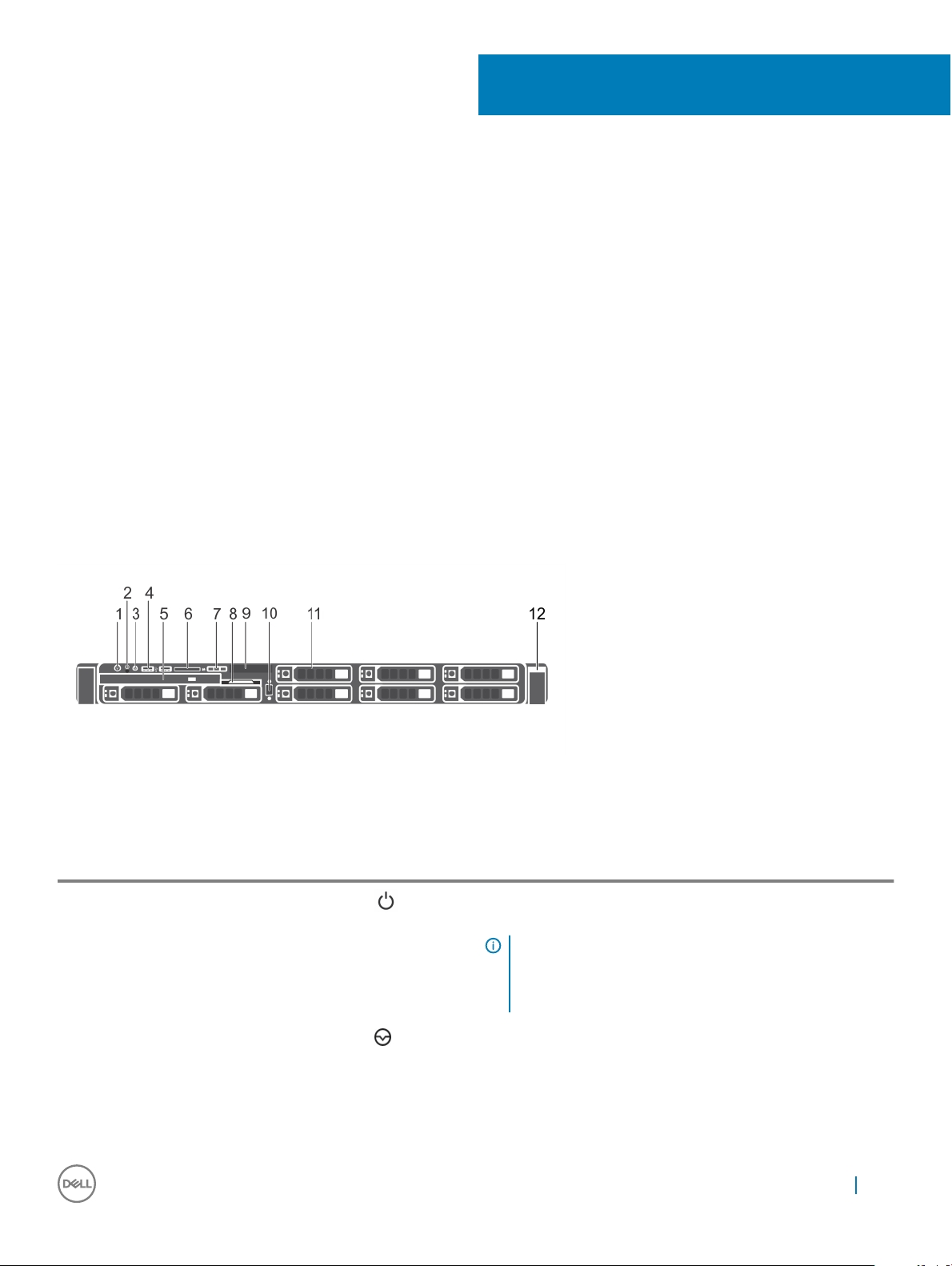
Front-panel features and indicators
1
Figure 1. Front-panel features and indicators—8 HDD system
Table 1. Front-panel features and indicators
Item Indicator, Button, or Connector Icon Description
1 Turn on indicator, power button The turn on indicator glows when the system is turn on. The power
button controls the power supply unit (PSU) output to the system.
NOTE: On ACPI-compliant operating systems (OSs),
turning o the system using the power button causes the
system to perform a graceful shutdown before power to
the system is turned o.
2 NMI button
Used to troubleshoot software and device driver errors when
running certain OSs. This button can be pressed using the end of a
paper clip.
Use this button only if directed to do so by qualied support
personnel or by the OS documentation.
About your system 7
Page 8

Item Indicator, Button, or Connector Icon Description
3 System identication button The identication buttons on the front- and back panels can be
used to locate a particular system within a rack. When one of these
buttons is pressed, the LCD panel on the front and the system
status indicator on the back ashes blue until one of the buttons is
pressed again.
Press to toggle the system ID to ON or OFF. If the system stops
responding during POST, press and hold the system ID button for
more than ve seconds to enter BIOS progress mode.
To reset the iDRAC (if not disabled on the iDRAC Setup page by
pressing F2) press and hold the button for more than 15 seconds.
4 USB management port/iDRAC
Direct (2)
5 Optical drive One optional SATA DVD-ROM drive or DVD+/-RW drive.
6 SD vFlash media card slot Allows you to insert a vFlash media card.
7 LCD menu buttons Allows you to navigate the control panel LCD menu.
8 Information tag A slide-out label panel which that allows you to record system
9 LCD panel Displays system ID, status information, and system error messages.
10 Quick Sync (optional)
Allows you to connect USB drives to the system or provides access
to the iDRAC Direct features. For more information, see the
Integrated Dell Remote Access Controller User's Guide at dell.com/
esmmanuals. The ports are USB 2.0-compliant.
NOTE: DVD devices are data only.
information, such as Service Tag, NIC, and MAC address.
The LCD lights blue during normal system operation. When the
system needs attention, the LCD lights amber and the LCD panel
displays an error code followed by descriptive text.
NOTE: If the system is connected to AC power and an
error is detected, the LCD lights amber regardless of
whether the system is turned on or turned o.
NOTE: By default, Quick Sync option is not available for
Dell Storage NX3330 system.
Indicates a Quick Sync-enabled system. The Quick Sync feature is
optional and requires a Quick Sync bezel. This feature allows
management of the system by using mobile devices. This feature
aggregates hardware or rmware inventory and various system level
diagnostic or error information that can be used in troubleshooting
the system. For more information, see the Integrated Dell Remote
Access Controller User’s Guide at dell.com/esmmanuals.
11 Video connector Allows you to connect a VGA display to the system.
12 HDDs (8) Up to eight 2.5 inch hot-swappable HDDs.
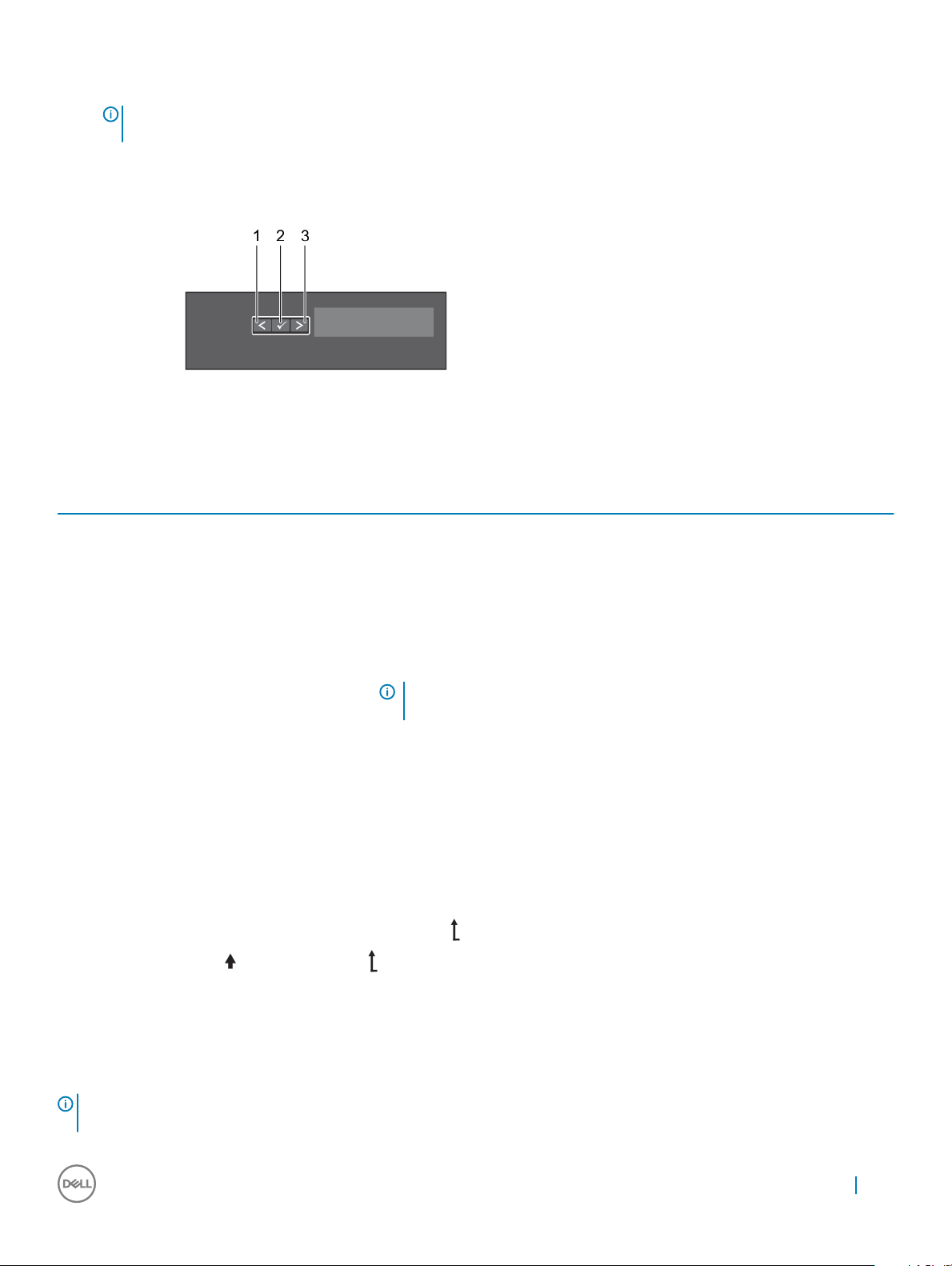
LCD panel
The LCD panel of your system provides system information, status, and error messages to indicate if the system is functioning correctly or
if the system needs attention. For more information about error messages, see the Dell Event and Error Messages Reference Guide at
Dell.com/openmanagemanuals >OpenManage software.
About your system
8
Page 9
• The LCD backlight turns blue during normal operating conditions.
• When the system needs attention, the LCD turns amber, and displays an error code followed by descriptive text.
NOTE: If the system is connected to a power source and an error is detected, the LCD turns amber regardless of whether
the system is turned on or o.
• The LCD backlight is turned o when the system is in standby mode and can be turned on by pressing either the Select, Left, or Right
button on the LCD panel.
• The LCD backlight remains o if LCD messaging is turned o using the iDRAC utility, the LCD panel, or other tools.
Figure 2. LCD panel features
Table 2. LCD panel features
Item Button Description
1 Left Moves the cursor back in one-step increments.
2 Select Selects the menu item highlighted by the cursor.
3 Right Moves the cursor forward in one-step increments.
During message scrolling:
• Press and hold the button to increase scrolling speed.
• Release the button to stop.
NOTE: The display stops scrolling when the button is released. After 45
seconds of inactivity, the display starts scrolling.
Viewing Home screen
The Home screen displays user-congurable information about the system. This screen is displayed during normal system operation when
there are no status messages or errors. When the system is in standby mode, the LCD backlight turns o after a few minutes of inactivity,
if there are no error messages.
1 To view the Home screen, press one of the three navigation buttons (Select, Left, or Right).
2 To navigate to the Home screen from another menu, complete the following steps:
a Press and hold the navigation button till the up arrow is displayed.
b Navigate to the using the up arrow
c Select the Home icon.
d On the Home screen, press the Select button to enter the main menu.
Setup menu
: When you select an option in the Setup menu, you must conrm the option before proceeding to the next
NOTE
action.
About your system 9
Page 10

Option Description
iDRAC Select DHCP or Static IP to congure the network mode. If Static IP is selected, the available elds are IP,
Subnet (Sub), and Gateway (Gtw). Select Setup DNS to enable DNS and to view domain addresses. Two
separate DNS entries are available.
Set error Select SEL to view LCD error messages in a format that matches the IPMI description in the SEL. This enables you
to match an LCD message with an SEL entry.
Select Simple to view LCD error messages in a simplied user-friendly description. For more information about
error messages, see the Dell Event and Error Messages Reference Guide at Dell.com/openmanagemanuals >
OpenManage software.
Set home Select the default information to be displayed on the Home screen. See View menu section for the options and
option items that can be set as the default on the Home screen.
Related links
View menu
View menu
NOTE: When you select an option in the View menu, you must conrm the option before proceeding to the next
action.
Option Description
iDRAC IP Displays the IPv4 or IPv6 addresses for iDRAC8. Addresses include DNS (Primary and Secondary), Gateway, IP,
and Subnet (IPv6 does not have Subnet).
MAC Displays the MAC addresses for iDRAC, iSCSI, or Network devices.
Name Displays the name of the Host, Model, or User String for the system.
Number Displays the Asset tag or the Service tag for the system.
Power Displays the power output of the system in BTU/hr or Watts. The display format can be congured in the Set
home submenu of the Setup menu.
Temperature Displays the temperature of the system in Celsius or Fahrenheit. The display format can be congured in the Set
home submenu of the Setup menu.
Back panel features and indicators
Figure 3. Back panel features and indicators—8 HDD system—3 PCIe expansion cards
10
About your system
Page 11
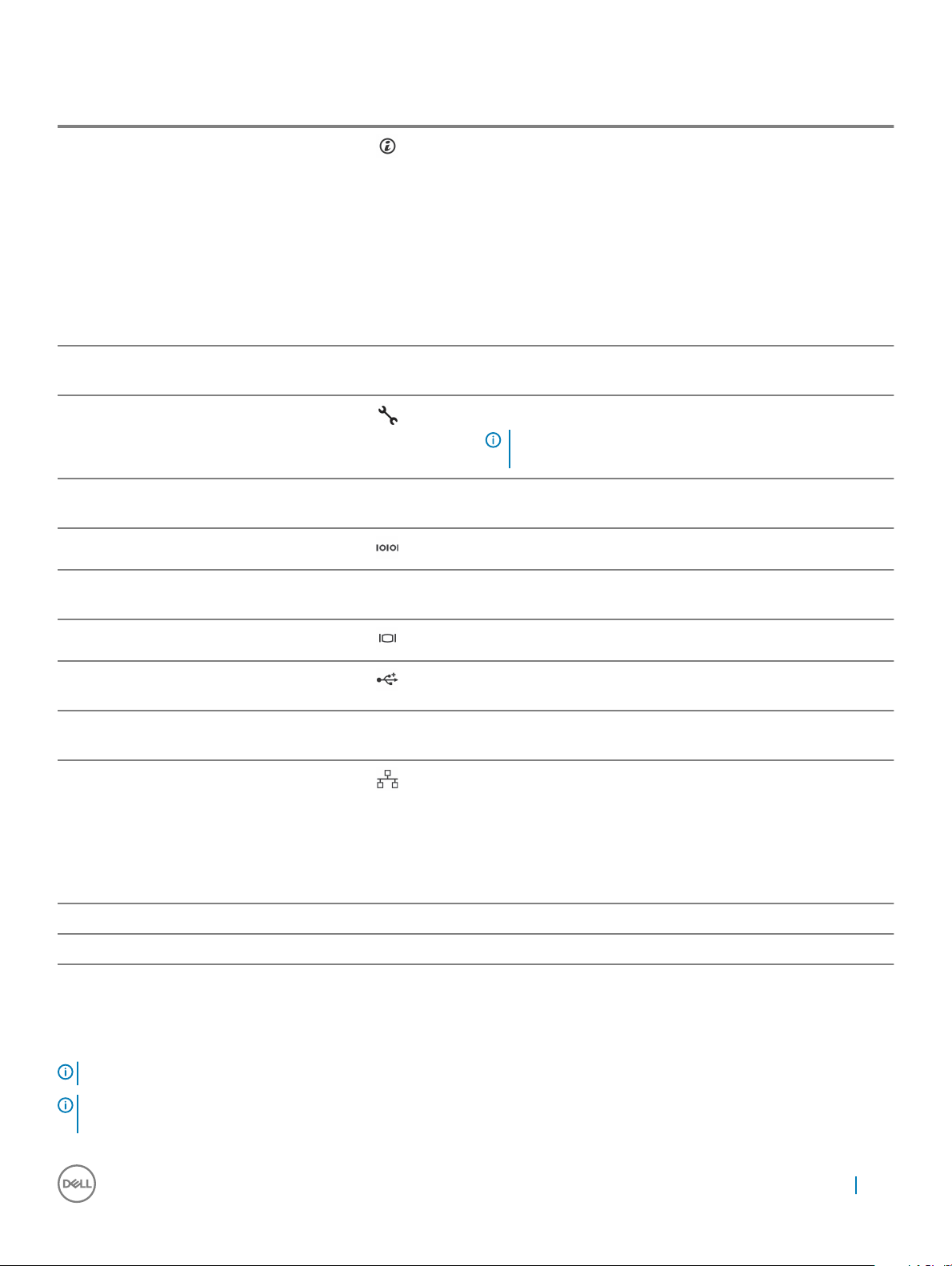
Table 3. Back panel features and indicators
Item Indicator, Button, or Connector Icon Description
1 System identication button The identication buttons on the front-and back panels can be used
to locate a particular system within a rack. When one of these
buttons is pressed, the LCD panel on the front and the system
status indicator on the back blinks until one of the buttons is
pressed again.
Press to toggle the system ID on and o. If the system stops
responding during POST, press and hold the system ID button for
more than ve seconds to enter BIOS progress mode.
To reset iDRAC (if not disabled on the iDRAC Setup page by
pressing F2), press and hold for more than 15 seconds.
2 System identication connector Allows you to connect the optional system status indicator
assembly through the optional cable management arm.
3 iDRAC8 Enterprise port Dedicated management port.
NOTE: The port is available for use only if the iDRAC8
Enterprise license is installed on your system.
4 LP PCIe expansion card slot
(riser 1)
5 Serial connector Allows you to connect a serial device to the system.
6 LP PCIe expansion card slot
(riser 2)
7 Video connector Allows you to connect a VGA display to the system.
8 USB connectors (2) Allows you to connect USB drives to the system. The ports are USB
9 LP PCIe expansion card slot
(riser 3)
10 Ethernet connectors (4) Four integrated 10/100/1000 Mbps NIC connectors
11 PSU 1 750 W AC PSUs
12 PSU 2 750 W AC PSUs
Allows you to connect a low prole PCIe expansion card.
Allows you to connect a low prole PCIe expansion card.
3.0-compliant.
Allows you to connect a low prole PCIe expansion card.
Or
Four integrated connectors:
• Two integrated 10/100/1000 Mbps NIC connectors
• Two integrated 100 Mbps/1 Gbps/10 Gbps SFP+ connectors
Diagnostic indicators
The diagnostic indicators on the system front panel display error status during system startup.
: The diagnostic indicators are not present if the system is equipped with an LCD display.
NOTE
NOTE: No diagnostic indicators are lit when the system is turned o. To start the system, plug it into a working power source and
press the power button.
About your system 11
Page 12

Table 4. Diagnostic indicators
Icon Description Condition Corrective action
Health indicator If the system is turned on, and in good
health, the indicator glows solid blue.
None required.
The indicator blinks amber if the
system is turned on or in standby, and
if any error exists (for example, a
failed fan or HDD).
HDD indicator The indicator blinks amber if a hard
drive experiences an error.
Electrical indicator The indicator blinks amber if the
system experiences an electrical error
(for example, voltage out of range, or
a failed PSU or voltage regulator).
Temperature
indicator
The indicator blinks amber if the
system experiences a thermal error
(for example, a temperature out of
range or fan failure).
See the System Event Log or system messages for the
specic issue. For more information about error messages,
see the Dell Event and Error Messages Reference Guide
at Dell.com/esmmanuals.
Invalid memory congurations can cause the system to
stop responding at startup without any video output. See
the Getting help section in this document.
See the System Event Log to determine the HDD that has
an error. Run the appropriate Online Diagnostics test.
Restart system and run embedded diagnostics (ePSA). If
the HDDs are congured in a RAID array, restart the
system and start the host adapter conguration utility
program.
See the System Event Log or system messages for the
specic issue. If it is because of an issue with the PSU,
check the LED on the PSU. Reseat the PSU by removing
and reinstalling it. If the issue persists, see the Getting
help section in this document.
Ensure that none of the following conditions exist:
• A cooling fan is removed or has failed.
• System cover, cooling shroud, EMI ller panel,
memory-module blank, or back-ller bracket is
removed.
• Ambient temperature is too high.
• External airow is obstructed.
Related links
Getting help
12
About your system
Memory indicator The indicator blinks amber if a
memory error occurs.
PCIe indicator The indicator blinks amber if a PCIe
card experiences an error.
See the Getting help section in this document.
See the system event log or system messages for the
location of the failed memory. Reinstall the memory
device. If the issue persists, see the Getting help section
in this document.
Restart the system. Update any required drivers for the
PCIe card. Reinstall the card. If the issue persists, see the
Getting help section in this document.
NOTE: For more information on supported PCIe
cards, see the Expansion Card Installation
Guidelines section in this document.
Page 13

Hard drive indicator codes
Figure 4. Hard drive indicators
1
Hard drive activity indicator 2 Hard drive status indicator
3 Hard drive
NOTE: If the hard drive is in Advanced Host Controller Interface (AHCI) mode, the status indicator (on the right side) does not
function and remains turned o.
Table 5. Hard drive indicator codes
Drive-status indicator pattern (RAID only) Condition
Blinks green two times per second Identifying drive or preparing for removal.
O Drive ready for insertion or removal.
NOTE: The drive status indicator remains o until all hard
drives are initialized after the system is turned on. Drives are
not ready for insertion or removal during this time.
Blinks green, amber, and turns o Predicted drive failure
Blinks amber four times per second Drive failed
Blinks green slowly Drive rebuilding
Steady green Drive online
Blinks green three seconds, amber three seconds, and turns
o six seconds
Rebuild aborted
iDRAC Direct LED indicator codes
The iDRAC Direct LED indicator lights up to indicate that the port is connected and is being used as a part of the iDRAC subsystem.
: The iDRAC Direct LED indicator does not turn on when the USB port is used in the USB mode.
NOTE
About your system 13
Page 14

Figure 5. iDRAC Direct LED indicator
1 iDRAC Direct status indicator
The iDRAC Direct LED indicator table describes iDRAC Direct activity when conguring iDRAC Direct by using the management port (USB
XML Import).
Table 6. iDRAC Direct LED indicators
Convention iDRAC Direct LED
A Green Turns green for a minimum of two seconds to indicate the start and end of a le transfer.
B Flashing green Indicates le transfer or any operation tasks.
C Green and turns o Indicates that the le transfer is complete.
D Not lit Indicates that the USB is ready to be removed or that a task is complete.
The following table describes iDRAC Direct activity when conguring iDRAC Direct by using your laptop and cable (Laptop Connect):
Table 7. iDRAC Direct LED indicator patterns
iDRAC Direct LED
indicator pattern
Solid green for two seconds Indicates that the laptop is connected.
Flashing green (on for two
seconds and o for two
seconds)
Turns o Indicates that the laptop is unplugged.
indicator pattern
Condition
Indicates that the laptop connected is recognized.
Condition
14 About your system
Page 15

NIC indicator codes
EachThe NIC on the back panel has an indicator that provides information about the network activity and link status. The activity LED
indicates whether the NIC is currently connected or not. The link LED indicates the speed of the connected network.
Figure 6. NIC indicators
1
link indicator 2 activity indicator
Table 8. NIC indicators
Convention Status Condition
A Link and activity indicators are o The NIC is not connected to the network.
B Link indicator is green The NIC is connected to a valid network at its
maximum port speed (1 Gbps or 10 Gbps).
C Link indicator is amber The NIC is connected to a valid network at less than
its maximum port speed.
D Activity indicator is ashing green Network data is being sent or received.
Power supply unit indicator codes
AC power supply units (PSUs) have an illuminated translucent handle that serves as an indicator and DC PSUs have an LED that serves as
an indicator. The indicator shows whether power is present or a power fault has occurred.
About your system
15
Page 16

Figure 7. AC PSU status indicator
1 AC PSU status indicator/handle
Table 9. AC PSU status indicators
Convention Power indicator
pattern
A Green A valid power source is connected to the PSU and the PSU is operational.
B Flashing green When the rmware of the PSU is being updated, the PSU handle ashes green.
C Flashing green and
turns o
D Flashing amber Indicates a problem with the PSU.
Condition
When hot-adding a PSU, the PSU handle ashes green ve times at 4 Hz rate and turns
o. This indicates a PSU mismatch with respect to eciency, feature set, health status,
and supported voltage.
NOTE: Ensure that both the PSUs are of the same capacity.
CAUTION: For AC PSUs, use only PSUs with the Extended Power Performance
(EPP) label on the back.
NOTE: Mixing PSUs from previous generations of Dell PowerEdge servers can
result in a PSU mismatch condition or failure to turn the system on.
CAUTION: When correcting a PSU mismatch, replace only the PSU with the
ashing indicator. Swapping the PSU to make a matched pair can result in an
error condition and unexpected system shutdown. To change from a high output
conguration to a low output conguration or vice versa, you must turn o the
system.
CAUTION: AC PSUs support both 220 V and 110 V input voltages with the
exception of Titanium PSUs, which support only 220 V. When two identical
PSUs receive dierent input voltages, they can output dierent wattages, and
trigger a mismatch.
16 About your system
CAUTION: If two PSUs are used, they must be of the same type and have the
same maximum output power.
Page 17

Convention Power indicator
pattern
E Not lit Power is not connected.
Condition
CAUTION: Combining AC and DC PSUs is not supported and triggers a
mismatch.
Figure 8. DC PSU status indicator
1
DC PSU status indicator
Table 10. DC PSU status indicators
Convention Power indicator pattern Condition
A Green A valid power source is connected to the PSU and that the PSU is operational.
B Flashing green When hot-adding a PSU, the PSU indicator ashes green. This indicates that there is a
PSU mismatch with respect to eciency, feature set, health status, and supported
voltage. Ensure that both the PSUs are of the same capacity.
C Flashing amber Indicates a problem with the PSU.
CAUTION: When correcting a PSU mismatch, replace only the PSU with the
ashing indicator. Swapping the PSU to make a matched pair can result in an
error condition and unexpected system shutdown. To change from a High
Output conguration to a Low Output conguration or vice versa, you must
turn o the system.
CAUTION: AC PSU support both 220 V and 110 V input voltages with the
exception of Titanium PSU, which support only 220 V. When two identical PSU
receive dierent input voltages, they can output dierent wattages, and
trigger a mismatch.
CAUTION: If two PSU are used, they must be of the same type and have the
same maximum output power.
About your system 17
Page 18

Convention Power indicator pattern Condition
CAUTION: Combining AC and DC PSU is not supported and triggers a
mismatch.
D Not lit Power is not connected.
Locating your system Service Tag
Your system is identied by a unique Express Service Code and Service Tag number. The Express Service Code and Service Tag are found
on the front of the system by pulling out the information tag. Alternatively, the information may be on a sticker on the chassis of the
system. This information is used by Dell to route support calls to the appropriate personnel.
18 About your system
Page 19

Documentation resources
This section provides information on the documentation resources for your server.
Table 11. Documentation resources for Dell Storage NX3330 NAS system
Task Document Location
2
Setting up your server For information about installing the server into a
rack, see the Rack documentation included with
your rack solution
For information about turning on the server and
the technical specications of your system, see the
Getting Started With Your System that shipped
with your system.
For information about Getting Started With Your
System that shipped with your system or the
Technical specications section in this document.
For information about overview of procedures for
setting up the storage system and internal storage,
see Setting Up Your Dell Storage NX3330 Network
Attached Storage System
Conguring your system For information about conguring, managing,
updating, and restoring the system, see the Dell
Storage Network Attached Storage (NAS)
Systems Running Windows Storage Server 2016 or
2012 R2 Administrator's Guide.
For information about the iDRAC features,
conguring and logging in to iDRAC, and managing
your system remotely, see the Integrated Dell
Remote Access Controller User's Guide.
Dell.com/storagemanuals
Dell.com/storagemanuals
Dell.com/idracmanuals
For information about understanding Remote
Access Controller Admin (RACADM)
subcommands and supported RACADM interfaces,
see the RACADM Command Line Reference Guide
for iDRAC.
For information about updating drivers and
rmware, see the Download rmware and drivers
section in this document.
Deploying your system For information about deploying the hardware and
installing the software on the appliance, see the
Dell Storage Network Attached Storage (NAS)
Systems Running Windows Storage Server 2016 or
2012 R2 Troubleshooting Guide
Managing your system For information about the features of the Dell
OpenManage Systems Management, see the Dell
Dell.com/idracmanuals
Dell.com/support/drivers
Dell.com/storagemanuals
Dell.com/openmanagemanuals
Documentation resources 19
Page 20

Task Document Location
OpenManage Systems Management Overview
Guide.
For information about setting up, using, and
troubleshooting OpenManage, see the Dell
OpenManage Server Administrator User’s Guide.
For information about installing, using, and
troubleshooting Dell OpenManage Essentials, see
the Dell OpenManage Essentials User’s Guide
For information about installing and using Dell
System E-Support Tool (DSET), see the Dell
System E-Support Tool (DSET) User's Guide.
For information about installing and using Active
System Manager (ASM), see the Active System
Manager User’s Guide.
Managing your system For understanding the features of Dell Lifecycle
Controller (LCC), see the Dell Lifecycle Controller
User’s Guide.
For information about partner programs enterprise
systems management, see the OpenManage
Connections Enterprise Systems Management
documents.
For information about connections and client
systems management, see the OpenManage
Connections Client Systems Management
documentation.
Dell.com/openmanagemanuals
Dell.com/openmanagemanuals
Dell.com/DSET
Dell.com/asmdocs
Dell.com/idracmanuals
Dell.com/
omconnectionsenterprisesystemsmanagement
Dell.com/dellclientcommandsuitemanuals
Working with the Dell
PowerEdge RAID controllers
Understanding event and error
messages
For information on understanding the features of
the Dell PowerEdge RAID controllers (PERC) and
deploying the PERC cards, see the Storage
controller documentation.
For information on checking the event and error
messages generated by the system rmware and
agents that monitor system components, see the
Dell Event and Error Messages Reference Guide
Dell.com/storagecontrollermanuals
Dell.com/openmanagemanuals > OpenManage
software
20
Documentation resources
Page 21

Technical specications
Table 12. Processor specication
Processor
Processor type Two Intel Haswell processor E5-2600 v3 product family
Table 13. Expansion bus specication
Expansion Bus
Bus type PCIe Generation 3
Expansion cards For a list of supported expansion cards, see the Expansion card
installation guidelines section in this document.
Expansion slots using riser card:
Riser 1 (Slot 1) One half-height, three fourth-length x8 link
(Slot 2) One half-height, half-length x16 link
3
Riser 2 (Slot 1) One half-height, half-length x8 link or one half-height, half-
length x8 link
NOTE: Both processors must be installed to use the slots
on riser 1 and the x16 link on riser 2.
(Slot 2) One half-height, half-length x8 link or one half-height,
half-length x16 link
Riser 3 (Slot 2) One half-height, half-length x8 link or one half-height,
half-length x16 link
Table 14. Power specication
Power
AC PSU (per PSU)
Wattage 750 W
Heat dissipation
NOTE: Heat dissipation is calculated using the PSU
wattage rating.
Voltage
NOTE: This system is also designed to be connected to
IT power systems with a phase to phase voltage not
exceeding 230 V.
2891 BTU/hr maximum (750 W PSU)
2843 BTU/hr maximum (750 W Titanium PSU)
100–240 V AC, autoranging, 50/60 Hz
Or
200–240 V AC, autoranging, 50/60 Hz, for 750 W Titanium PSU
Technical specications 21
Page 22

Table 15. Memory specication
Memory
Architecture 1866 MT/ and 2133 MT/s registered Error Correcting Code (ECC)
DIMMs
Support for Advanced ECC or memory-optimized operation
Support for LRDIMMs
Memory module sockets Twenty-four 288-pin
Memory module capacities
LRDIMM 4 GB, 8 GB, 16 GB, or 32 GB single-, dual-, or quad-ranked
RDIMM 4 GB, 8 GB, or 32 GB single-, dual-, or quad-ranked
16 GB single- or dual-ranked
Minimum RAM 2 GB with a single processor
4 GB with two processors
Maximum RAM
LRDIMM Up to 768 GB
RDIMM Up to 512 GB
Table 16. Drive specication
Drives
HDDs
8—HDD systems Up to eight 2.5 inch, internal, hot-swappable SAS, SATA, or
Nearline SAS HDDs
Optical drive One optional SATA DVD-ROM drive or DVD+/-RW drive
NOTE: DVD devices are data only.
Table 17. Connector specication
Connectors
Back
NIC Four 10/100/1000 Mbps or two 10/100/1000 Mbps and two 100
Mbps/1 Gbps/10 Gbps
Serial DB-9 Serial Port connector
USB Two 4-pin, USB 3.0-compliant
Video 15-pin VGA
Front
8 HDD systems
USB Two 4-pin, USB 3.0-compliant
Video 15-pin VGA
External vFlash card vFlash memory card slot
22 Technical specications
Page 23

Connectors
NOTE: The card slot is available for use only if the
iDRAC8 Enterprise license is installed on your system.
Internal
USB One 4-pin, USB 3.0-compliant
Internal Dual SD Module (IDSDM) Two optional ash memory card slots with the internal SD module
NOTE: One card slot is dedicated for redundancy.
Table 18. Video specication
Video
Video type Integrated VGA controller
Video memory 16 MB shared
Table 19. Expanded operating temperature
Expanded Operating Temperature
NOTE: When operating in the expanded temperature range, system performance may be impacted.
NOTE: When operating in the expanded temperature range, ambient temperature warnings may be reported on the LCD and
in the System Event Log.
< 10% of annual operating hours Continuous Operation 5 °C–40°C at 5% to 85% RH with 29°C
dew point.
NOTE: Outside the standard operating temperature
(10°C–35°C), the system can operate continuously down
to 5°C or as high as 40°C.
For temperatures between 35°C- 40°C, derate maximum
allowable temperature by 1°C per 175 m above 950 m (1°F per 319
ft).
< 1% of annual operating hours –5 °C–45°C at 5% to 90% RH with 29°C (84.2°F) maximum
dew point.
NOTE: Outside the standard operating temperature
(10°C–35°C), the system can operate down to –5°C or
up to 45°C for a maximum of 1% of its annual operating
hours.
For temperatures between 40 °C–45 °C, derate maximum
allowable dry bulb temperature by 1°C per 125 m above 950 m
(1°F per 228 ft).
Expanded Operating Temperature Restrictions
• Do not perform a cold startup below 5°C.
• The operating temperature specied is for a maximum altitude
of 3048 m (10,000 ft).
• PCIe SSD and 1.8-inch SSDs are not supported.
• GPU is not supported.
• 145 W and Workstation CPU (160 W) processors are not
supported.
• Two PSUs are required and one PSU failure is not supported.
Technical specications 23
Page 24

Expanded Operating Temperature
• Non-Dell qualied peripheral cards and/or peripheral cards
greater than 25 W are not supported.
Table 20. Environmental specication
Environmental
NOTE: For additional information about environmental measurements for specic system congurations, see Dell.com/
environmental_datasheets.
Temperature
Maximum temperature gradient (operating and storage) 20°C/h (36°F/h)
Storage temperature limits –40°C–65°C (–40°F–149°F)
Relative humidity
Storage 5% to 95% RH with 33°C (91 °F) maximum dew point.
Atmosphere must be non-condensing always.
Temperature (continuous operation)
Temperature ranges (for altitude less than 950 m or 3117 ft) 10 °C–35°C (50 °F–95°F) with no direct sunlight on the
equipment.
Humidity percentage range 10% to 80% Relative Humidity with 26°C (78.8°F) maximum
dew point.
Maximum vibration
Operating 0.26 G
Storage 1.87 G
at 5 Hz to 350 Hz (all operation orientations).
rms
at 10 Hz to 500 Hz for 15 min (all six sides tested).
rms
Maximum shock
Operating One shock pulse in the positive z axis of 31 G for 2.6 ms in all
operational orientations.
Storage Six consecutively executed shock pulses in the positive and
negative x, y, and z axes (one pulse on each side of the system)
of 71 G for up to 2 ms.
Maximum altitude
Operating
3,048 m (10,000 ft)
Storage 12,000 m (39,370 ft).
Operating altitude de-rating
Up to 35°C (95°F) Maximum temperature is reduced by 1°C/300 m (1°F/547 ft)
above 950 m (3,117 ft).
35 °C–40°C (95 °F–104°F) Maximum temperature is reduced by 1°C/175 m (1°F/319 ft)
above 950 m (3,117 ft).
40 °C–45°C (104 °F–113°F) Maximum temperature is reduced by 1°C/125 m (1°F/228 ft)
above 950 m (3,117 ft).
Particulate contamination
24 Technical specications
Page 25

Environmental
NOTE: This section denes the limits to help avoid IT equipment damage and/or failure from particulates and gaseous
contamination. If it is determined that levels of particulates or gaseous pollution are beyond the limits specied below and are
the reason for the damage and/or failures to your equipment, it may be necessary for you to re-mediate the environmental
conditions that are causing the damage and/or failures. Re-mediation of environmental conditions will be the responsibility of
the customer.
Air ltration
NOTE: Applies to data center environments only. Air
ltration requirements do not apply to IT equipment
designed to be used outside a data center, in
environments such as an oce or factory oor.
Conductive dust
NOTE: Applies to data center and non-data center
environments.
Corrosive dust
NOTE: Applies to data center and non-data center
environments.
Gaseous contamination
NOTE: Maximum corrosive contaminant levels measured at ≤50% relative humidity.
Copper coupon corrosion rate <300 Å/month per Class G1 as dened by ANSI/ISA71.04-1985.
Silver coupon corrosion rate <200 Å/month as dened by AHSRAE TC9.9.
Related links
Expansion card installation guidelines
Data center air ltration as dened by ISO Class 8 per ISO
14644-1 with a 95 percent upper condence limit.
NOTE: Air entering the data center must have MERV11
or MERV13 ltration.
Air must be free from conductive dust, zinc whiskers, or other
conductive particles.
• Air must be free of corrosive dust.
• Residual dust present in the air must have a deliquescent
point less than 60% relative humidity.
Technical
specications 25
Page 26

4
Initial system setup and conguration
Setting up your system
Complete the following steps to set up your system:
1 Unpack the system.
2 Install the system into the rack. For more information about installing the system into the rack, see your system Rack Installation
Placemat
3 Connect the peripherals to the system.
4 Connect the system to its electrical outlet.
5 Turn the system on by pressing the power button or by using iDRAC.
6 Turn on the attached peripherals.
iDRAC conguration
The Integrated Dell Remote Access Controller (iDRAC) is designed to make system administrators more productive and improve the overall
availability of Dell systems. iDRAC alerts administrators to system issues, helps them perform remote system management, and reduces the
need for physical access to the system.
at Dell.com/poweredgemanuals.
Options to set up iDRAC IP address
You must congure the initial network settings based on your network infrastructure to enable the communication to and from iDRAC. You
can set up the IP address by using one of the following interfaces:
Interfaces
iDRAC Settings
utility
Dell Deployment
Toolkit
Dell Lifecycle
Controller
Chassis or Server
LCD panel
You must use the default iDRAC IP address 192.168.0.120 to congure the initial network settings, including setting up DHCP or a static IP
for iDRAC.
: To access iDRAC, ensure that you install the iDRAC port card or connect the network cable to the Ethernet connector 1
NOTE
on the system board.
NOTE: Ensure that you change the default user name and password after setting up the iDRAC IP address.
Related links
LCD panel
Document/Section
See Dell Integrated Dell Remote Access Controller User's Guide at Dell.com/idracmanuals
See Dell Deployment Toolkit User’s Guide at Dell.com/openmanagemanuals
See Dell Lifecycle Controller User’s Guide at Dell.com/idracmanuals
See the LCD panel section
26 Initial system setup and conguration
Page 27

Log in to iDRAC
You can log in to iDRAC as:
• iDRAC user
• Microsoft Active Directory user
• Lightweight Directory Access Protocol (LDAP) user
The default user name and password are root and calvin. You can also log in by using Single Sign-On or Smart Card.
NOTE: You must have iDRAC credentials to log in to iDRAC.
For more information about logging in to iDRAC and iDRAC licenses, see the latest Integrated Dell Remote Access Controller User's Guide
at http://www.dell.com/support/home/us/en/19/Products/software/remote_ent_sys_mgmt/rmte_ent_sys_rmte_access_cntrllr.
Options to install the operating system
If the system is shipped without an operating system, install the supported operating system by using one of the following resources:
Table 21. Resources to install the operating system
Resources Location
Dell Systems Management Tools and Documentation media Dell.com/operatingsystemmanuals
Dell Lifecycle Controller Dell.com/idracmanuals
Dell OpenManage Deployment Toolkit Dell.com/openmanagemanuals
Dell certied VMware ESXi Dell.com/virtualizationsolutions
Supported operating systems on Dell PowerEdge systems Dell.com/ossupport
Installation and How-to videos for supported operating systems on
Dell PowerEdge systems
Supported Operating Systems for Dell PowerEdge Systems
Methods to download rmware and drivers
You can download the rmware and drivers by using any of the following methods:
Table 22. Firmware and drivers
Methods Location
From the Dell Support site Dell.com/support/home
Using Dell Remote Access Controller Lifecycle Controller (iDRAC
with LC)
Using Dell Repository Manager (DRM) Dell.com/openmanagemanuals
Using Dell OpenManage Essentials (OME) Dell.com/openmanagemanuals
Using Dell Server Update Utility (SUU) Dell.com/openmanagemanuals
Using Dell OpenManage Deployment Toolkit (DTK) Dell.com/openmanagemanuals
Dell.com/idracmanuals
Manage your system
This section provides the information about server management software.
Initial system setup and
conguration 27
Page 28

Server
Management
Software
Description
OpenManage
OpenManage
Essentials
Remote Access
Controller with Dell
Lifecycle Controller
(iDRAC with LC)
Partner Programs
Enterprise Systems
Management
OpenManage
Connections Client
Systems
Management
The Dell OpenManage Server Administrator provides a comprehensive one-to-one systems management solution
for both local and remote servers and their storage controllers and Direct Attached Storage (DAS).
For information about OpenManage documents, see Dell.com/openmanagemanuals.
Dell OpenManage Essentials is the newest one-to-many management console for managing Dell PowerEdge
servers and direct-attached storage as it provides a simple and easy interface for system administrators to
maximize the uptime and health of Dell systems.
For information about OpenManage documents, see Dell.com/openmanagemanuals.
iDRAC with Dell Lifecycle Controller allows administrators to deploy, update, monitor, and manage Dell servers from
any location without the use of agents in a one-to-one or one-to-many method. This out-of-band management
allows the updates to be sent from Dell or appropriate third-party consoles directly to iDRAC with Dell Lifecycle
Controller on a Dell PowerEdge server, regardless of the operating system that may or may not be running.
For information about Remote Enterprise Systems Management documents, see Dell.com/idracmanuals.
For information about OpenManage Connections Enterprise Systems Management documents, see Dell.com/
omconnectionsenterprisesystemsmanagement.
For information about OpenManage Connections Client Systems Management documents, see Dell.com/
dellclientcommandsuitemanuals.
28 Initial system setup and conguration
Page 29

Pre-operating system management applications
You can manage basic settings and features of a system without booting to the operating system by using the system rmware.
Options to manage the pre-operating system applications
Your system has the following options to manage the pre-operating system applications:
• System Setup
• Boot Manager
• Dell Lifecycle Controller
• Preboot Execution Environment (PXE)
System Setup
By using the System Setup screen, you can congure the BIOS settings, iDRAC settings, and device settings of your system.
: Help text for the selected eld is displayed in the graphical browser by default. To view the help text in the text browser,
NOTE
press F1.
5
You can access system setup by using two methods:
• Standard graphical browser — The browser is enabled by default.
• Text browser — The browser is enabled by using Console Redirection.
Viewing System Setup
To view the System Setup screen, perform the following steps:
1 Turn on, or restart your system.
2 Press F2 immediately after you see the following message:
F2 = System Setup
NOTE
: If your operating system begins to load before you press F2, wait for the system to nish booting, and then
restart your system and try again.
System Setup details
The System Setup Main Menu screen details are explained as follows:
Option
System BIOS Enables you to congure BIOS settings.
Description
iDRAC Settings Enables you to congure iDRAC settings.
Pre-operating system management applications 29
Page 30

Option Description
The iDRAC settings utility is an interface to set up and congure the iDRAC parameters by using UEFI (Unied
Extensible Firmware Interface). You can enable or disable various iDRAC parameters by using the iDRAC settings
utility. For more information about this utility, see Integrated Dell Remote Access Controller User’s Guide at
Dell.com/idracmanuals.
Device Settings Enables you to congure device settings.
System BIOS
You can use the System BIOS screen to edit specic functions such as boot order, system password, setup password, set the RAID mode,
and enable or disable USB ports.
Viewing System BIOS
To view the System BIOS screen, perform the following steps:
1 Turn on, or restart your system.
2 Press F2 immediately after you see the following message:
F2 = System Setup
NOTE
: If your operating system begins to load before you press F2, wait for the system to nish booting, and then
restart your system and try again.
3 On the System Setup Main Menu screen, click System BIOS.
System BIOS Settings details
The System BIOS Settings screen details are explained as follows:
Option
System Information Species information about the system such as the system model name, BIOS version, and Service Tag.
Memory Settings Species information and options related to the installed memory.
Processor Settings Species information and options related to the processor such as speed and cache size.
SATA Settings Species options to enable or disable the integrated SATA controller and ports.
Boot Settings Species options to specify the boot mode (BIOS or UEFI). Enables you to modify UEFI and BIOS boot settings.
Network Settings Species options to change the network settings.
Integrated Devices Species options to manage integrated device controllers and ports and specify related features and options.
Serial
Communication
System Prole
Settings
System Security Species options to congure the system security settings, such as system password, setup password, Trusted
Miscellaneous
Settings
Description
Species options to manage the serial ports and specify related features and options.
Species options to change the processor power management settings, memory frequency, and so on.
Platform Module (TPM) security. It also manages the power and NMI buttons on the system.
Species options to change the system date, time, and so on.
30 Pre-operating system management applications
Page 31

Boot Settings
You can use the Boot Settings screen to set the boot mode to either BIOS or UEFI. It also enables you to specify the boot order.
Viewing Boot Settings
To view the Boot Settings screen, perform the following steps:
1 Turn on, or restart your system.
2 Press F2 immediately after you see the following message:
F2 = System Setup
NOTE: If your operating system begins to load before you press F2, wait for the system to nish booting, and then
restart your system and try again.
3 On the System Setup Main Menu screen, click System BIOS.
4 On the System BIOS screen, click Boot Settings.
Boot Settings details
The Boot Settings screen details are explained as follows:
Option
Boot Mode Enables you to set the boot mode of the system.
Boot Sequence
Retry
Hard-Disk Failover Species the hard drive that is booted in the event of a hard drive failure. The devices are selected in the Hard-
Boot Option
Settings
BIOS Boot Settings Enables or disables BIOS boot options.
UEFI Boot Settings Enables or disables UEFI Boot options. The Boot options include IPv4 PXE and IPv6 PXE. This option is set to
Description
CAUTION: Switching the boot mode may prevent the system from booting if the operating system is
not installed in the same boot mode.
If the operating system supports UEFI, you can set this option to UEFI. Setting this eld to BIOS allows
compatibility with non-UEFI operating systems. This option is set to
NOTE: Setting this eld to UEFI disables the BIOS Boot Settings menu. Setting this eld to BIOS
disables the UEFI Boot Settings menu.
Enables or disables the Boot Sequence Retry feature. If this option is set to Enabled and the system fails to boot,
the system reattempts the boot sequence after 30 seconds. This option is set to Enabled by default.
Disk Drive Sequence on the Boot Option Setting menu. When this option is set to Disabled, only the rst hard
drive in the list is attempted to boot. When this option is set to Enabled, all hard drives are attempted to boot in
the order selected in the Hard-Disk Drive Sequence. This option is not enabled for UEFI Boot Mode.
Congures the boot sequence and the boot devices.
NOTE: This option is enabled only if the boot mode is BIOS.
IPv4 by default.
NOTE: This option is enabled only if the boot mode is UEFI.
BIOS by default.
Pre-operating system management applications 31
Page 32

Choosing the system boot mode
System Setup enables you to specify one of the following boot modes for installing your operating system:
• BIOS boot mode (the default) is the standard BIOS-level boot interface.
• Unied Extensible Firmware Interface (UEFI) (the default) boot mode is an enhanced 64-bit boot interface. If you have congured your
system to boot to UEFI mode, it replaces the system BIOS.
1 From the System Setup Main Menu, click Boot Settings, and select Boot Mode.
2 Select the boot mode you want the system to boot into.
CAUTION: Switching the boot mode may prevent the system from booting if the operating system is not installed in
the same boot mode.
3 After the system boots in the specied boot mode, proceed to install your operating system from that mode.
NOTE: Operating systems must be UEFI-compatible to be installed from the UEFI boot mode. DOS and 32-bit operating systems
do not support UEFI and can only be installed from the BIOS boot mode.
NOTE: For the latest information about supported operating systems, go to Dell.com/ossupport.
Changing the boot order
You may have to change the boot order if you want to boot from a USB key or an optical drive. The following instructions may vary if you
have selected
1 On the System Setup Main Menu screen, click System BIOS > Boot Settings.
2 Click Boot Option Settings > Boot Sequence.
3 Use the arrow keys to select a boot device, and use the plus (+) and minus (-) sign keys to move the device down or up in the order.
4 Click Exit, and then click Yes to save the settings on exit.
BIOS for Boot Mode.
Network Settings
You can use the Network Settings screen to modify PXE device settings. The network settings option is available only in the UEFI mode.
: The BIOS does not control network settings in the BIOS mode. For the BIOS boot mode, the optional Boot ROM of the
NOTE
network controllers handles the network settings.
Viewing Network Settings
To view the Network Settings screen, perform the following steps:
1 Turn on, or restart your system.
2 Press F2 immediately after you see the following message:
F2 = System Setup
: If your operating system begins to load before you press F2, wait for the system to nish booting, and then
NOTE
restart your system and try again.
3 On the System Setup Main Menu screen, click System BIOS.
4 On the System BIOS screen, click Network Settings.
32
Pre-operating system management applications
Page 33

Network Settings screen details
The Network Settings screen details are explained as follows:
Option Description
PXE Device n (n = 1
to 4)
PXE Device n
Settings(n = 1 to 4)
Enables or disables the device. When enabled, a UEFI boot option is created for the device.
Enables you to control the conguration of the PXE device.
UEFI iSCSI Settings
You can use the iSCSI Settings screen to modify iSCSI device settings. The iSCSI Settings option is available only in the UEFI boot mode.
BIOS does not control network settings in the BIOS boot mode. For the BIOS boot mode, the option ROM of the network controller
handles the network settings.
Viewing UEFI iSCSI Settings
To view the UEFI iSCSI Settings screen, perform the following steps:
1 Turn on, or restart your system.
2 Press F2 immediately after you see the following message:
F2 = System Setup
NOTE
: If your operating system begins to load before you press F2, wait for the system to nish booting, and then
restart your system and try again.
3 On the System Setup Main Menu screen, click System BIOS.
4 On the System BIOS screen, click Network Settings.
5 On the Network Settings screen, click UEFI iSCSI Settings.
UEFI iSCSI Settings details
The UEFI ISCSI Settings screen details are explained as follows:
Option
ISCSI Initiator Name Species the name of the iSCSI initiator (iqn format).
ISCSI Device n (n =
1 to 4)
Description
Enables or disables the iSCSI device. When disabled, a UEFI boot option is created for the iSCSI device
automatically.
System Security
You can use the System Security screen to perform specic functions such as setting the system password, setup password and disabling
the power button.
Viewing System Security
To view the System Security screen, perform the following steps:
1 Turn on, or restart your system.
2 Press F2 immediately after you see the following message:
F2 = System Setup
: If your operating system begins to load before you press F2, wait for the system to nish booting, and then
NOTE
restart your system and try again.
Pre-operating system management applications 33
Page 34

3 On the System Setup Main Menu screen, click System BIOS.
4 On the System BIOS screen, click System Security.
System Security Settings details
The System Security Settings screen details are explained as follows:
Option Description
Intel AES-NI Improves the speed of applications by performing encryption and decryption by using the Advanced Encryption
Standard Instruction Set (AES-NI). This option is set to Enabled by default.
System Password Sets the system password. This option is set to Enabled by default and is read-only if the password jumper is not
installed in the system.
Setup Password Sets the setup password. This option is read-only if the password jumper is not installed in the system.
Password Status Locks the system password. This option is set to Unlocked by default.
TPM Security
TPM Information Changes the operational state of the TPM. This option is set to No Change by default.
TPM Status Species the TPM status.
TPM Command
Intel TXT Enables or disables the Intel Trusted Execution Technology (TXT) option. To enable the Intel TXT option,
Power Button Enables or disables the power button on the front of the system. This option is set to Enabled by default.
NMI Button Enables or disables the NMI button on the front of the system. This option is set to Disabled by default.
AC Power Recovery Sets how the system behaves after AC power is restored to the system. This option is set to Last by default.
AC Power Recovery
Delay
User Dened Delay
(60s to 240s)
UEFI Variable
Access
Secure Boot Enables Secure Boot, where the BIOS authenticates each pre-boot image by using the certicates in the Secure
Secure Boot Policy When Secure Boot policy is set to Standard, the BIOS uses the system manufacturer’s key and certicates to
Secure Boot Policy
Summary
NOTE: The TPM menu is available only when the TPM module is installed.
Enables you to control the reporting mode of the TPM. The TPM Security option is set to O by default. You can
only modify the TPM Status, TPM Activation, and Intel TXT elds if the TPM Status eld is set to either On with
Pre-boot Measurements or On without Pre-boot Measurements.
CAUTION: Clearing the TPM results in the loss of all keys in the TPM. The loss of TPM keys may aect
booting to the operating system.
Clears all the contents of the TPM. The TPM Clear option is set to No by default.
virtualization technology and TPM Security must be enabled with Pre-boot measurements. This option is set to O
by default.
Sets the time delay for the system to power up after AC power is restored to the system. This option is set to
Immediate by default.
Sets the User Dened Delay option when the User Dened option for AC Power Recovery Delay is selected.
Provides varying degrees of securing UEFI variables. When set to Standard (the default), UEFI variables are
accessible in the operating system per the UEFI specication. When set to Controlled, selected UEFI variables are
protected in the environment and new UEFI boot entries are forced to be at the end of the current boot order.
Boot Policy. Secure Boot is disabled by default.
authenticate pre-boot images. When Secure Boot policy is set to Custom, the BIOS uses the user-dened key and
certicates. Secure Boot policy is set to Standard by default.
Species the list of certicates and hashes that secure boot uses to authenticate images.
34 Pre-operating system management applications
Page 35

Secure Boot Custom Policy Settings
Secure Boot Custom Policy Settings is displayed only when Secure Boot Policy is set to Custom.
Viewing Secure Boot Custom Policy Settings
To view the Secure Boot Custom Policy Settings screen, perform the following steps:
1 Turn on, or restart your system.
2 Press F2 immediately after you see the following message:
F2 = System Setup
NOTE: If your operating system begins to load before you press F2, wait for the system to nish booting, and then
restart your system and try again.
3 On the System Setup Main Menu screen, click System BIOS.
4 On the System BIOS screen, click System Security.
5 On the System Security screen, click Secure Boot Custom Policy Settings.
Secure Boot Custom Policy Settings details
The Secure Boot Custom Policy Settings screen details are explained as follows:
Option Description
Platform Key Imports, exports, deletes, or restores the platform key (PK).
Key Exchange Key
Database
Authorized
Signature Database
Forbidden
Signature Database
Enables you to import, export, delete, or restore entries in the Key Exchange Key (KEK) Database.
Imports, exports, deletes, or restores entries in the Authorized Signature Database (db).
Imports, exports, deletes, or restores entries in the Forbidden Signature Database (dbx).
Creating a system and setup password
Prerequisites
Ensure that the password jumper is enabled. The password jumper enables or disables the system password and setup password features.
For more information, see the System board jumper settings section.
: If the password jumper setting is disabled, the existing system password and setup password are deleted and you need
NOTE
not provide the system password to boot the system.
Steps
1 To enter System Setup, press F2 immediately after turning on or rebooting your system.
2 On the System Setup Main Menu screen, click System BIOS > System Security.
3 On the System Security screen, verify that Password Status is set to Unlocked.
4 In the System Password eld, type your system password, and press Enter or Tab.
Use the following guidelines to assign the system password:
• A password can have up to 32 characters.
• The password can contain the numbers 0 through 9.
• Only the following special characters are allowed: space, (”), (+), (,), (-), (.), (/), (;), ([), (\), (]), (`).
A message prompts you to reenter the system password.
5 Reenter the system password, and click OK.
6 In the Setup Password eld, type your setup password and press Enter or Tab.
A message prompts you to reenter the setup password.
Pre-operating system management applications
35
Page 36

7 Reenter the setup password, and click OK.
8 Press Esc to return to the System BIOS screen. Press Esc again.
A message prompts you to save the changes.
NOTE: Password protection does not take eect until the system reboots.
Using your system password to secure your system
About this task
If you have assigned a setup password, the system accepts your setup password as an alternate system password.
Steps
1 Turn on or reboot your system.
2 Type the system password and press Enter.
Next steps
When Password Status is set to Locked, type the system password and press Enter when prompted at reboot.
NOTE: If an incorrect system password is typed, the system displays a message and prompts you to reenter your password. You
have three attempts to type the correct password. After the third unsuccessful attempt, the system displays an error message
that the system has stopped functioning and must be turned o. Even after you turn o and restart the system, the error
message is displayed until the correct password is entered.
Deleting or changing system and setup password
Prerequisites
: You cannot delete or change an existing system or setup password if the Password Status is set to Locked.
NOTE
Steps
1 To enter System Setup, press F2 immediately after turning on or restarting your system.
2 On the System Setup Main Menu screen, click System BIOS > System Security.
3 On the System Security screen, ensure that Password Status is set to Unlocked.
4 In the System Password eld, alter or delete the existing system password, and then press Enter or Tab.
5 In the Setup Password eld, alter or delete the existing setup password, and then press Enter or Tab.
If you change the system and setup password, a message prompts you to reenter the new password. If you delete the system and
setup password, a message prompts you to conrm the deletion.
6 Press Esc to return to the System BIOS screen. Press Esc again, and a message prompts you to save the changes.
Operating with a setup password enabled
If Setup Password is set to Enabled, type the correct setup password before modifying the system setup options.
If you do not type the correct password in three attempts, the system displays the following message:
Invalid Password! Number of unsuccessful password attempts: <x> System Halted! Must power down.
Even after you turn o and restart the system, the error message is displayed until the correct password is typed. The following options are
exceptions:
• If System Password is not set to Enabled and is not locked through the Password Status option, you can assign a system password.
For more information, see the System Security Settings screen section.
• You cannot disable or change an existing system password.
: You can use the password status option with the setup password option to protect the system password from
NOTE
unauthorized changes.
36 Pre-operating system management applications
Page 37

Related links
System Security Settings details
System Information
You can use the System Information screen to view system properties such as Service Tag, system model name, and the BIOS version.
Viewing System Information
To view the System Information screen, perform the following steps:
1 Turn on, or restart your system.
2 Press F2 immediately after you see the following message:
F2 = System Setup
NOTE: If your operating system begins to load before you press F2, wait for the system to nish booting, and then
restart your system and try again.
3 On the System Setup Main Menu screen, click System BIOS.
4 On the System BIOS screen, click System Information.
System Information details
The System Information screen details are explained as follows:
Option
System Model
Name
System BIOS
Version
System
Management
Engine Version
System Service Tag Species the system Service Tag.
System
Manufacturer
System
Manufacturer
Contact
Information
System CPLD
Version
UEFI Compliance
Version
Description
Species the system model name.
Species the BIOS version installed on the system.
Species the current version of the Management Engine rmware.
Species the name of the system manufacturer.
Species the contact information of the system manufacturer.
Species the current version of the system complex programmable logic device (CPLD) rmware.
Species the UEFI compliance level of the system rmware.
Pre-operating system management applications 37
Page 38

Memory Settings
You can use the Memory Settings screen to view all the memory settings and enable or disable specic memory functions, such as system
memory testing and node interleaving.
Viewing Memory Settings
To view the Memory Settings screen, perform the following steps:
1 Turn on, or restart your system.
2 Press F2 immediately after you see the following message:
F2 = System Setup
NOTE: If your operating system begins to load before you press F2, wait for the system to nish booting, and then
restart your system and try again.
3 On the System Setup Main Menu screen, click System BIOS.
4 On the System BIOS screen, click Memory Settings.
Memory Settings details
The Memory Settings screen details are explained as follows:
Option
System Memory
Size
System Memory
Type
System Memory
Speed
System Memory
Voltage
Video Memory Species the amount of video memory.
System Memory
Testing
Memory Operating
Mode
Node Interleaving Species if Non-Uniform Memory architecture (NUMA) is supported. If this eld is set to Enabled, memory
Snoop Mode Species the Snoop Mode options. The Snoop Mode options available are Home Snoop, Early Snoop, and Cluster
Description
Species the memory size in the system.
Species the type of memory installed in the system.
Species the system memory speed.
Species the system memory voltage.
Species whether the system memory tests are run during system boot. Options are Enabled and Disabled. This
option is set to Disabled by default.
Species the memory operating mode. The options available are Optimizer Mode, Advanced ECC Mode, Mirror
Mode, Spare Mode, Spare with Advanced ECC Mode, Dell Fault Resilient Mode and Dell NUMA Fault Resilient
Mode. This option is set to Optimizer Mode by default.
NOTE: The Memory Operating Mode option can have dierent default and available options based on
the memory conguration of your system.
NOTE: The Dell Fault Resilient Mode option establishes an area of memory that is fault resilient. This
mode can be used by an operating system that supports the feature to load critical applications or
enables the operating system kernel to maximize system availability.
interleaving is supported if a symmetric memory conguration is installed. If the eld is set to Disabled, the system
supports NUMA (asymmetric) memory congurations. This option is set to Disabled by default.
on Die. This option is set to Early Snoop by default. This eld is available only when the Node Interleaving is set to
Disabled.
38 Pre-operating system management applications
Page 39

Processor Settings
You can use the Processor Settings screen to view the processor settings, and perform specic functions such as enabling virtualization
technology, hardware prefetcher, and logical processor idling.
Viewing Processor Settings
To view the Processor Settings screen, perform the following steps:
1 Turn on, or restart your system.
2 Press F2 immediately after you see the following message:
F2 = System Setup
NOTE: If your operating system begins to load before you press F2, wait for the system to nish booting, and then
restart your system and try again.
3 On the System Setup Main Menu screen, click System BIOS.
4 On the System BIOS screen, click Processor Settings.
Processor Settings details
The Processor Settings screen details are explained as follows:
Option
Logical Processor Enables or disables the logical processors and displays the number of logical processors. If this option is set to
QPI Speed Enables you to control QuickPath Interconnect data rate settings.
Alternate RTID
(Requestor
Transaction ID)
Setting
Virtualization
Technology
Address Translation
Service (ATS)
Adjacent Cache
Line Prefetch
Hardware
Prefetcher
DCU Streamer
Prefetcher
DCU IP Prefetcher Enables or disables the Data Cache Unit (DCU) IP prefetcher. This option is set to Enabled by default.
Execute Disable Enables you to run the disable memory protection technology. This option is set to Enabled by default.
Logical Processor
Idling
Congurable TDP Enables you to recongure the processor Thermal Design Power (TDP) levels during POST based on the power
Description
Enabled, the BIOS displays all the logical processors. If this option is set to Disabled, the BIOS displays only one
logical processor per core. This option is set to Enabled by default.
Modies Requestor Transaction IDs, which are QPI resources. This option is set to Disabled by default.
NOTE: Enabling this option may negatively impact the overall system performance.
Enables or disables the additional hardware capabilities provided for virtualization. This option is set to Enabled by
default.
Denes the Address Translation Cache (ATC) for devices to cache the DMA transactions. This option provides an
interface between CPU and DMA Memory Management to a chipset's Address Translation and Protection Table to
translate DMA addresses to host addresses. This option is set to Enabled by default.
Optimizes the system for applications that need high utilization of sequential memory access. This option is set to
Enabled by default. You can disable this option for applications that need high utilization of random memory
access.
Enables or disables the hardware prefetcher. This option is set to Enabled by default.
Enables or disables the Data Cache Unit (DCU) streamer prefetcher. This option is set to Enabled by default.
Enables you to improve the energy eciency of a system. It uses the operating system core parking algorithm and
parks some of the logical processors in the system which in turn allows the corresponding processor cores to
transition into a lower power idle state. This option can only be enabled if the operating system supports it. It is set
to Disabled by default.
and thermal delivery capabilities of the system. TDP veries the maximum heat the cooling system is needed to
dissipate. This option is set to Nominal by default.
Pre-operating system management applications 39
Page 40

Option Description
NOTE: This option is only available on certain stock keeping units (SKUs) of the processors.
X2Apic Mode Enables or disables the X2Apic mode.
Dell Controlled
Turbo
Controls the turbo engagement. Enable this option only when System Prole is set to Performance.
NOTE: Depending on the number of installed CPUs, there may be up to four processor listings.
Number of Cores
per Processor
Processor 64-bit
Support
Processor Core
Speed
Processor 1
Controls the number of enabled cores in each processor. This option is set to All by default.
Species if the processor(s) support 64-bit extensions.
Species the maximum core frequency of the processor.
The following settings are displayed for each processor installed in the system:
Option Description
Family-ModelStepping
Brand Species the brand name.
Level 2 Cache Species the total L2 cache.
Level 3 Cache Species the total L3 cache.
Number of Cores Species the number of cores per processor.
SATA Settings
NOTE: Depending on the number of CPUs, there may be up to four processors listed.
Species the family, model, and stepping of the processor as dened by Intel.
You can use the SATA Settings screen to view the SATA settings of SATA devices and enable RAID on your system.
Viewing SATA Settings
To view the SATA Settings screen, perform the following steps:
1 Turn on, or restart your system.
2 Press F2 immediately after you see the following message:
F2 = System Setup
NOTE
: If your operating system begins to load before you press F2, wait for the system to nish booting, and then
restart your system and try again.
3 On the System Setup Main Menu screen, click System BIOS.
4 On the System BIOS screen, click SATA Settings.
SATA Settings details
The SATA Settings screen details are explained as follows:
Option
Embedded SATA Enables the embedded SATA option to be set to O, ATA, AHCI, or RAID modes. This option is set to AHCI by
Description
default.
40 Pre-operating system management applications
Page 41

Option Description
Security Freeze
Lock
Write Cache Enables or disables the command for Embedded SATA drives during POST.
Port A Sets the drive type of the selected device. For Embedded SATA settings in ATA mode, set this eld to Auto to
Sends Security Freeze Lock command to the Embedded SATA drives during POST. This option is applicable only
for ATA and AHCI modes.
enable BIOS support. Set it to OFF to turn o BIOS support.
For AHCI or RAID mode, BIOS support is always enabled.
Option Description
Model Species the drive model of the selected device.
Drive Type Species the type of drive attached to the SATA port.
Capacity Species the total capacity of the hard drive. This eld is undened for removable media
devices such as optical drives.
Port B Sets the drive type of the selected device. For Embedded SATA settings in ATA mode, set this eld to Auto to
enable BIOS support. Set it to OFF to turn o BIOS support.
For AHCI or RAID mode, BIOS support is always enabled.
Option Description
Model Species the drive model of the selected device.
Drive Type Species the type of drive attached to the SATA port.
Capacity Species the total capacity of the hard drive. This eld is undened for removable media
devices such as optical drives.
Port C Sets the drive type of the selected device. For Embedded SATA settings in ATA mode, set this eld to Auto to
enable BIOS support. Set it to OFF to turn o BIOS support.
For AHCI or RAID mode, BIOS support is always enabled.
Option Description
Model Species the drive model of the selected device.
Drive Type Species the type of drive attached to the SATA port.
Capacity Species the total capacity of the hard drive. This eld is undened for removable media
devices such as optical drives.
Port D Sets the drive type of the selected device. For Embedded SATA settings in ATA mode, set this eld to Auto to
enable BIOS support. Set it to OFF to turn o BIOS support.
For AHCI or RAID mode, BIOS support is always enabled.
Option Description
Model Species the drive model of the selected device.
Drive Type Species the type of drive attached to the SATA port.
Capacity Species the total capacity of the hard drive. This eld is undened for removable media
devices such as optical drives.
Port E Sets the drive type of the selected device. For Embedded SATA settings in ATA mode, set this eld to Auto to
enable BIOS support. Set it to OFF to turn o BIOS support.
For AHCI or RAID mode, BIOS support is always enabled.
Pre-operating system management applications 41
Page 42

Option Description
Option Description
Model Species the drive model of the selected device.
Drive Type Species the type of drive attached to the SATA port.
Capacity Species the total capacity of the hard drive. This eld is undened for removable media
devices such as optical drives.
Port F Sets the drive type of the selected device. For Embedded SATA settings in ATA mode, set this eld to Auto to
enable BIOS support. Set it to OFF to turn o BIOS support.
For AHCI or RAID mode, BIOS support is always enabled.
Option Description
Model Species the drive model of the selected device.
Drive Type Species the type of drive attached to the SATA port.
Capacity Species the total capacity of the hard drive. This eld is undened for removable media
devices such as optical drives.
Port G Sets the drive type of the selected device. For Embedded SATA settings in ATA mode, set this eld to Auto to
enable BIOS support. Set it to OFF to turn o BIOS support.
For AHCI or RAID mode, BIOS support is always enabled.
Option Description
Model Species the drive model of the selected device.
Drive Type Species the type of drive attached to the SATA port.
Capacity Species the total capacity of the hard drive. This eld is undened for removable media
devices such as optical drives.
Port H Sets the drive type of the selected device. For Embedded SATA settings in ATA mode, set this eld to Auto to
enable BIOS support. Set it to OFF to turn o BIOS support.
For AHCI or RAID mode, BIOS support is always enabled.
Option Description
Model Species the drive model of the selected device.
Drive Type Species the type of drive attached to the SATA port.
Capacity Species the total capacity of the hard drive. This eld is undened for removable media
devices such as optical drives.
Port I Sets the drive type of the selected device. For Embedded SATA settings in ATA mode, set this eld to Auto to
enable BIOS support. Set it to OFF to turn o BIOS support.
For AHCI or RAID mode, BIOS support is always enabled.
Option Description
Model Species the drive model of the selected device.
Drive Type Species the type of drive attached to the SATA port.
Capacity Species the total capacity of the hard drive. This eld is undened for removable media
devices such as optical drives.
Port J Sets the drive type of the selected device. For Embedded SATA settings in ATA mode, set this eld to Auto to
enable BIOS support. Set it to OFF to turn o BIOS support.
42 Pre-operating system management applications
Page 43

Option Description
For AHCI or RAID mode, BIOS support is always enabled.
Option Description
Model Species the drive model of the selected device.
Drive Type Species the type of drive attached to the SATA port.
Capacity Species the total capacity of the hard drive. This eld is undened for removable media
devices such as optical drives.
Integrated Devices
You can use the Integrated Devices screen to view and congure the settings of all integrated devices including the video controller,
integrated RAID controller, and the USB ports.
Viewing Integrated Devices
To view the Integrated Devices screen, perform the following steps:
1 Turn on, or restart your system.
2 Press F2 immediately after you see the following message:
F2 = System Setup
NOTE
: If your operating system begins to load before you press F2, wait for the system to nish booting, and then
restart your system and try again.
3 On the System Setup Main Menu screen, click System BIOS.
4 On the System BIOS screen, click Integrated Devices.
Integrated Devices details
The Integrated Devices screen details are explained as follows:
Option
USB 3.0 Setting Enables or disables the USB 3.0 support. Enable this option only if your operating system supports USB 3.0. If you
User Accessible
USB Ports
Internal USB Port Enables or disables the internal USB port. This option is set to Enabled by default.
Integrated RAID
Controller
Integrated Network
Card 1
Embedded NIC1
and NIC2
Description
disable this option, devices operate at USB 2.0 speed. USB 3.0 is enabled by default.
Enables or disables the USB ports. Selecting Only Back Ports On disables the front USB ports, selecting All Ports
O disables all USB ports. The USB keyboard and mouse operate during boot process in certain operating systems.
After the boot process is complete, the USB keyboard and mouse do not work if the ports are disabled.
NOTE: Selecting Only Back Ports On and All Ports O disables the USB management port and also
restricts access to iDRAC features.
Enables or disables the integrated RAID controller. This option is set to Enabled by default.
Enables or disables the integrated network card.
NOTE: The Embedded NIC1 and NIC2 options are only available on systems that do not have Integrated
Network Card 1.
Enables or disables the Embedded NIC1 and NIC2 options. If set to Disabled, the NIC may still be available for
shared network access by the embedded management controller. The embedded NIC1 and NIC2 options are only
available on systems that do not have Network Daughter Cards (NDCs). The Embedded NIC1 and NIC2 option is
Pre-operating system management applications 43
Page 44

Option Description
mutually exclusive with the Integrated Network Card 1 option. Congure the Embedded NIC1 and NIC2 option by
using the NIC management utilities of the system.
I/OAT DMA Engine Enables or disables the I/OAT option. Enable only if the hardware and software support the feature.
Embedded Video
Controller
Current State of
Embedded Video
Controller
SR-IOV Global
Enable
OS Watchdog
Timer
Memory Mapped
I/O above 4 GB
Slot Disablement Enables or disables the available PCIe slots on your system. The slot disablement feature controls the conguration
Enables or disables the Embedded Video Controller option. This option is set to Enabled by default.
Displays the current state of the embedded video controller. The Current State of Embedded Video Controller
option is a read-only eld. If the Embedded Video Controller is the only display capability in the system (that is, no
add-in graphics card is installed), then the Embedded Video Controller is automatically used as the primary display
even if the Embedded Video Controller setting is set to Disabled.
Enables or disables the BIOS conguration of Single Root I/O Virtualization (SR-IOV) devices. This option is set to
Disabled by default.
If your system stops responding, this watchdog timer aids in the recovery of your operating system. When this
option is set to Enabled, the operating system initializes the timer. When this option is set to Disabled (the
default), the timer does not have any eect on the system.
Enables or disables the support for PCIe devices that need large amounts of memory. This option is set to Enabled
by default.
of PCIe cards installed in the specied slot. Slots must be disabled only when the installed peripheral card prevents
booting into the operating system or causes delays in system startup. If the slot is disabled, both the Option ROM
and UEFI drivers are disabled.
Serial Communication
You can use the Serial Communication screen to view the properties of the serial communication port.
Viewing Serial Communication
To view the Serial Communication screen, perform the following steps:
1 Turn on, or restart your system.
2 Press F2 immediately after you see the following message:
F2 = System Setup
NOTE
: If your operating system begins to load before you press F2, wait for the system to nish booting, and then
restart your system and try again.
3 On the System Setup Main Menu screen, click System BIOS.
4 On the System BIOS screen, click Serial Communication.
Serial Communication details
The Serial Communication screen details are explained as follows:
Option
Serial
Communication
Description
Selects serial communication devices (Serial Device 1 and Serial Device 2) in BIOS. BIOS console redirection can
also be enabled and the port address can be specied. This option is set to Auto by default.
Serial Port Address Enables you to set the port address for serial devices. This option is set to Serial Device 1=COM2, Serial Device
2=COM1 by default.
NOTE: You can use only Serial Device 2 for the Serial Over LAN (SOL) feature. To use console
redirection by SOL, congure the same port address for console redirection and the serial device.
44 Pre-operating system management applications
Page 45

Option Description
NOTE: Every time the system boots, the BIOS syncs the serial MUX setting saved in iDRAC. The serial
MUX setting can independently be changed in iDRAC. Loading the BIOS default settings from within
the BIOS setup utility may not always revert the serial MUX setting to the default setting of Serial
Device 1.
External Serial
Connector
Failsafe Baud Rate Species the failsafe baud rate for console redirection. The BIOS attempts to determine the baud rate
Remote Terminal
Type
Redirection After
Boot
Enables you to associate the External Serial Connector to Serial Device 1, Serial Device 2, or the Remote Access
Device by using this option.
NOTE: Only Serial Device 2 can be used for Serial Over LAN (SOL). To use console redirection by SOL,
congure the same port address for console redirection and the serial device.
NOTE: Every time the system boots, the BIOS syncs the serial MUX setting saved in iDRAC. The serial
MUX setting can independently be changed in iDRAC. Loading the BIOS default settings from within
the BIOS setup utility may not always revert this setting to the default setting of Serial Device 1.
automatically. This failsafe baud rate is used only if the attempt fails, and the value must not be changed. This
option is set to 115200 by default.
Sets the remote console terminal type. This option is set to VT 100/VT 220 by default.
Enables or disables the BIOS console redirection when the operating system is loaded. This option is set to
Enabled by default.
System Prole Settings
You can use the System Prole Settings screen to enable specic system performance settings such as power management.
Viewing System Prole Settings
To view the System Prole Settings screen, perform the following steps:
1 Turn on, or restart your system.
2 Press F2 immediately after you see the following message:
F2 = System Setup
NOTE
: If your operating system begins to load before you press F2, wait for the system to nish booting, and then
restart your system and try again.
3 On the System Setup Main Menu screen, click System BIOS.
4 On the System BIOS screen, click System Prole Settings.
System Prole Settings details
The System Prole Settings screen details are explained as follows:
Option
System Prole Sets the system prole. If you set the System Prole option to a mode other than Custom, the BIOS automatically
CPU Power
Management
Description
sets the rest of the options. You can only change the rest of the options if the mode is set to Custom. This option
is set to Performance Per Watt Optimized (DAPC) by default. DAPC is Dell Active Power Controller.
NOTE: All the parameters on the system prole setting screen are available only when the System
Prole option is set to Custom.
Sets the CPU power management. This option is set to System DBPM (DAPC) by default. DBPM is Demand-
Based Power Management.
Pre-operating system management applications 45
Page 46

Option Description
Memory Frequency Sets the speed of the system memory. You can select Maximum Performance, Maximum Reliability, or a specic
speed.
Turbo Boost Enables or disables the processor to operate in the turbo boost mode. This option is set to Enabled by default.
Energy Ecient
Turbo
C1E Enables or disables the processor to switch to a minimum performance state when it is idle. This option is set to
C States Enables or disables the processor to operate in all available power states. This option is set to Enabled by default.
Collaborative CPU
Performance
Control
Memory Patrol
Scrub
Memory Refresh
Rate
Uncore Frequency Enables you to select the Processor Uncore Frequency option.
Enables or disables the Energy Ecient Turbo option.
Energy Ecient Turbo (EET) is a mode of operation where a processor’s core frequency is adjusted to be within
the turbo range based on workload.
Enabled by default.
Enables or disables the CPU power management option. When set to Enabled, the CPU power management is
controlled by the OS DBPM and the System DBPM (DAPC). This option is set to Disabled by default.
Sets the memory patrol scrub frequency. This option is set to Standard by default.
Sets the memory refresh rate to either 1x or 2x. This option is set to 1x by default.
Dynamic mode enables the processor to optimize power resources across the cores and uncore during runtime.
The optimization of the uncore frequency to either save power or optimize performance is inuenced by the
setting of the Energy Eciency Policy option.
Energy Ecient
Policy
Number of Turbo
Boot Enabled Cores
for Processor 1
Monitor/Mwait Enables the Monitor/Mwait instructions in the processor. This option is set to Enabled for all system proles,
Enables you to select the Energy Ecient Policy option.
The CPU uses the setting to manipulate the internal behavior of the processor and determines whether to target
higher performance or better power savings.
NOTE: If there are two processors installed in the system, you see an entry for Number of Turbo Boost
Enabled Cores for Processor 2.
Controls the number of turbo boost enabled cores for processor 1. The maximum number of cores is enabled by
default.
except Custom by default.
NOTE: This option can be disabled only if the C States option in the Custom mode is set to disabled.
NOTE: When C States is set to Enabled in the Custom mode, changing the Monitor/Mwait setting does
not impact the system power or performance.
46 Pre-operating system management applications
Page 47

Miscellaneous Settings
You can use the Miscellaneous Settings screen to perform specic functions such as updating the asset tag and changing the system
date and time.
Viewing Miscellaneous Settings
To view the Miscellaneous Settings screen, perform the following steps:
1 Turn on, or restart your system.
2 Press F2 immediately after you see the following message:
F2 = System Setup
NOTE: If your operating system begins to load before you press F2, wait for the system to nish booting, and then
restart your system and try again.
3 On the System Setup Main Menu screen, click System BIOS.
4 On the System BIOS screen, click Miscellaneous Settings.
Miscellaneous Settings details
The Miscellaneous Settings screen details are explained as follows:
Option
System Time Enables you to set the time on the system.
System Date Enables you to set the date on the system.
Asset Tag Species the asset tag and enables you to modify it for security and tracking purposes.
Keyboard NumLock Enables you to set whether the system boots with the NumLock enabled or disabled. This option is set to On by
F1/F2 Prompt on
Error
Load Legacy Video
Option ROM
In-System
Characterization
Description
default.
NOTE: This option does not apply to 84-key keyboards.
Enables or disables the F1/F2 prompt on error. This option is set to Enabled by default. The F1/F2 prompt also
includes keyboard errors.
Enables you to determine whether the system BIOS loads the legacy video (INT 10H) option ROM from the video
controller. Selecting Enabled in the operating system does not support UEFI video output standards. This eld is
available only for UEFI boot mode. You cannot set the option to Enabled if UEFI Secure Boot mode is enabled.
Enables or disables In-System Characterization. This option is set to Disabled by default. The two other options
are Enabled and Enabled - No Reboot.
NOTE: The default setting for In-System Characterization is subject to change in future BIOS releases.
When enabled, In-System Characterization (ISC) executes during POST upon detecting relevant change(s) in
system conguration to optimize system power and performance. ISC takes about 20 seconds to execute, and
system reset is needed for ISC results to be applied. The Enabled - No Reboot option executes ISC and continues
without applying ISC results until the next time system reset occurs. The Enabled option executes ISC and forces
an immediate system reset so that ISC results can be applied. It takes the system longer to be ready due to the
forced system reset. When disabled, ISC does not execute.
iDRAC Settings utility
The iDRAC settings utility is an interface to set up and congure the iDRAC parameters by using UEFI. You can enable or disable various
iDRAC parameters by using the iDRAC settings utility.
Pre-operating system management applications
47
Page 48

NOTE: Accessing some of the features on the iDRAC settings utility needs the iDRAC Enterprise License upgrade.
For more information about using iDRAC, see Dell Integrated Dell Remote Access Controller User's Guide at Dell.com/idracmanuals.
Entering the iDRAC Settings utility
1 Turn on or restart the managed system.
2 Press F2 during Power-on Self-test (POST).
3 On the System Setup Main Menu page, click iDRAC Settings.
The iDRAC Settings screen is displayed.
Changing the thermal settings
The iDRAC settings utility enables you to select and customize the thermal control settings for your system.
1 Click iDRAC Settings > Thermal.
2 Under SYSTEM THERMAL PROFILE > Thermal Prole, select one of the following options:
• Default Thermal Prole Settings
• Maximum Performance (Performance Optimized)
• Minimum Power (Performance per Watt Optimized)
3 Under USER COOLING OPTIONS, set the Fan Speed Oset, Minimum Fan Speed, and Custom Minimum Fan Speed.
4 Click Back > Finish > Yes.
Device Settings
Device Settings enables you to congure device parameters.
Dell Lifecycle Controller
Dell Lifecycle Controller (LC) provides advanced embedded systems management capabilities including system deployment, conguration,
update, maintenance, and diagnosis. LC is delivered as part of the iDRAC out-of-band solution and Dell system embedded Unied
Extensible Firmware Interface (UEFI) applications.
Embedded systems management
The Dell Lifecycle Controller provides advanced embedded systems management throughout the system’s lifecycle. The Dell Lifecycle
Controller can be started during the boot sequence and can function independently of the operating system.
NOTE
: Certain platform congurations may not support the full set of features provided by the Dell Lifecycle
Controller.
For more information about setting up the Dell Lifecycle Controller, conguring hardware and rmware, and deploying the operating system,
see the Dell Lifecycle Controller documentation at Dell.com/idracmanuals.
48
Pre-operating system management applications
Page 49

Boot Manager
The Boot Manager screen enables you to select boot options and diagnostic utilities.
Viewing Boot Manager
To enter Boot Manager:
1 Turn on, or restart your system.
2 Press F11 when you see the following message:
F11 = Boot Manager
If your operating system begins to load before you press F11, allow the system to complete the booting, and then restart your system
and try again.
Boot Manager main menu
Menu item
Continue Normal
Boot
One-shot Boot
Menu
Launch System
Setup
Launch Lifecycle
Controller
System Utilities Enables you to launch System Utilities menu such as System Diagnostics and UEFI shell.
Description
The system attempts to boot to devices starting with the rst item in the boot order. If the boot attempt fails, the
system continues with the next item in the boot order until the boot is successful or no more boot options are
found.
Enables you to access boot menu, where you can select a one-time boot device to boot from.
Enables you to access System Setup.
Exits the Boot Manager and invokes the Dell Lifecycle Controller program.
One-shot BIOS boot menu
One-shot BIOS boot menu enables you to select a boot device to boot from.
System Utilities
System Utilities contains the following utilities that can be launched:
• Launch Diagnostics
• BIOS Update File Explorer
• Reboot System
PXE boot
You can use the Preboot Execution Environment (PXE) option to boot and congure the networked systems, remotely.
: To access the PXE boot option, boot the system and then press F12. The system scans and displays the active networked
NOTE
systems.
Pre-operating system management applications 49
Page 50

Installing and removing system components
This section provides information about installing and removing the system components.
Topics:
• Safety instructions
• Before working inside your system
• After working inside your system
• Recommended tools
• Front bezel (optional)
• Removing system cover
• Installing the system cover
• Inside system
• Cooling shroud
• System memory
• Hard disk drives
• Optical drive (optional)
• Cooling fans
• Expansion cards and expansion card riser
• SD vFlash card (optional)
• Integrated storage controller card
• Network daughter card
• Processors and heat sinks
• PSUs
• System battery
• Hard disk drive backplane
• Control panel
• VGA module
• System board
• Trusted Platform Module
6
Safety instructions
WARNING
yourself.
WARNING: Opening or removing the system cover while the system is powered on may expose you to a risk of electric shock.
CAUTION: Do not operate the system without the cover for a duration exceeding ve minutes.
CAUTION: Many repairs may only be done by a certied service technician. You should only perform troubleshooting and simple
repairs as authorized in your product documentation, or as directed by the online or telephone service and support team. Damage
due to servicing that is not authorized by Dell is not covered by your warranty. Read and follow the safety instructions that are
shipped with your product.
NOTE: Dell recommends that you always use a static mat and static strap while working on components inside the system.
50 Installing and removing system components
: Whenever you need to lift the system, get others to assist you. To avoid injury, do not attempt to lift the system by
Page 51

NOTE: To ensure proper operation and cooling, all bays in the system and system fans must be populated always with either a
component or with a blank.
Before working inside your system
Prerequisites
Follow the safety guidelines listed in the Safety instructions section.
Steps
1 Turn o the system, including any attached peripherals.
2 Disconnect the system from the electrical outlet and disconnect the peripherals.
3 If installed, remove the front bezel.
4 If applicable, remove the system from the rack.
For more information, see the Rack Installation placemat at Dell.com/poweredgemanuals.
5 Remove the system cover.
Related links
Safety instructions
After working inside your system
Prerequisites
Follow the safety guidelines listed in the Safety instructions section.
Steps
1 Install the system cover.
2 If applicable, install the system into the rack.
For more information, see the Rack Installation placemat at Dell.com/poweredgemanuals.
3 If removed, install the front bezel.
4 Reconnect the peripherals and connect the system to the electrical outlet.
5 Turn on the system, including any attached peripherals.
Related links
Safety instructions
Recommended tools
You need the following tools to perform the removal and installation procedures:
• Key to the bezel lock.
The key is needed only if your system includes a bezel.
• Phillips #1 screwdriver
• Phillips #2 screwdriver
• Torx #T6, #T8, #T10, and #T15 screwdrivers
• Wrist grounding strap
You need the following tools to assemble the cables for a DC power supply unit.
• AMP 90871-1 hand-crimping tool or equivalent
• Tyco Electronics 58433-3 or equivalent
• Wire-stripper pliers to remove insulation from size 10 AWG solid or stranded, insulated copper wire
: Use alpha wire part number 3080 or equivalent (65/30 stranding).
NOTE
Installing and removing system components 51
Page 52

Front bezel (optional)
The front bezel is attached to the front side of the server and prevents accidents while removing the hard drive or when pressing the reset
or power button. The front bezel can also be locked for additional security.
Removing the optional front bezel
Prerequisites
Follow the safety guidelines listed in the Safety instructions section.
Steps
1 Locate and remove the bezel key.
NOTE: The bezel key is attached to the back of the bezel.
2 Unlock the bezel by using the key.
3 Slide the release latch up, and pull the left end of the bezel.
4 Unhook the right end, and remove the bezel.
Figure 9. Removing the optional front bezel
1
bezel lock 2 front bezel
Related links
Safety instructions
Installing front bezel
1 Hook the right end of the bezel onto the chassis.
2 Fit the free end of the bezel onto the system.
3 Secure the bezel with the key lock.
52
Installing and removing system components
Page 53

Removing system cover
Prerequisites
1 Ensure that you read the Safety instructions section in this document.
2 Turn o the system, including any attached peripherals.
3 Disconnect the system from the electrical outlet and peripherals.
4 Remove the optional bezel. For more information, see the Removing the front bezel section in this document.
Steps
1 Turn the latch release lock to the unlock position.
2 Lift the cover release latch and remove the system cover.
Figure 10. Removing and installing the system
1
latch release lock 2 system cover
3 latch
Related links
Safety instructions
Removing the optional front bezel
Installing the system cover
Prerequisites
1 Follow the safety guidelines listed in the Safety instructions section.
2 Follow the procedure listed in the Before working inside your system section.
3 Ensure that all internal cables are connected and placed out of the way, and no tools or extra parts are left inside the system.
Steps
1 Align the slots on the system cover with the tabs on the chassis.
2 Push the system cover latch down.
Installing and removing system components
53
Page 54

The system cover slides forward and the slots on the system cover engage with the tabs on the chassis. The system cover latch locks
into place when the system cover is completely engaged with the tabs on the chassis.
3 Rotate the latch release lock clockwise to the locked position.
Next steps
1 If removed, install the front bezel.
2 Reconnect the peripherals and connect the system to the electrical outlet.
3 Turn on the system, including any attached peripherals.
4 Follow the procedure listed in the After working inside your system section.
Related links
Safety instructions
Before working inside your system
After working inside your system
Inside system
CAUTION: Many repairs may only be done by a certied service technician. You should only perform troubleshooting and simple
repairs as authorized in your product documentation, or as directed by the online or telephone service and support team. Damage
due to servicing that is not authorized by Dell is not covered by your warranty. Read and follow the safety instructions that are
shipped with your product.
NOTE: Components that are hot-swappable are marked orange and touch points on the components are marked blue.
54 Installing and removing system components
Page 55

Figure 11. Inside the system — 8 HDD system
1
control panel assembly 2 cooling fans (7)
3 processor 1 4 DIMMs (6)
5 PSU connector 6 PSU (2)
7 riser card 3 8 network daughter card
9 riser card 2 10 riser card 1
11 DIMMs (6) 12 processor 2
13 DIMMs (12) 14 HDD backplane
15 HDD
Cooling shroud
The cooling shroud aerodynamically directs the airow across the entire system. The airow passes through all the critical parts of the
system, where the vacuum pulls air across the entire surface area of the heat sink, thus allowing increased cooling.
Installing and removing system components
55
Page 56

Removing the cooling shroud
Prerequisites
CAUTION: Many repairs may only be done by a certied service technician. You should only perform troubleshooting and simple
repairs as authorized in your product documentation, or as directed by the online or telephone service and support team. Damage
due to servicing that is not authorized by Dell is not covered by your warranty. Read and follow the safety instructions that are
shipped with your product.
CAUTION: Never operate your system with the cooling shroud removed. The system may get overheated quickly, resulting in
shutdown of the system and loss of data.
1 Follow the safety guidelines listed in the Safety instructions section.
2 Follow the procedure listed in the Before working inside your system section.
3 If installed, remove the full-length PCIe card.
Steps
Holding the touch points, lift the cooling shroud away from the system.
Next steps
1 Install the cooling shroud.
2 If required, install the full-length PCIe card.
3 Follow the procedure listed in the After working inside your system section.
Related links
Safety instructions
Before working inside your system
After working inside your system
Installing the cooling shroud
Prerequisites
CAUTION
repairs as authorized in your product documentation, or as directed by the online or telephone service and support team. Damage
due to servicing that is not authorized by Dell is not covered by your warranty. Read and follow the safety instructions that are
shipped with your product.
1 Follow the safety guidelines listed in the Safety instructions section.
2 Follow the procedure listed in the Before working inside your system section.
3 If applicable, route the cables inside the system along the chassis wall and secure the cables by using the cable-securing bracket.
Steps
1 Align the tabs on the cooling shroud with the securing slots on the chassis.
2 Lower the cooling shroud into the chassis until it is rmly seated.
Next steps
1 If removed, install the full-length PCIe card.
2 Follow the procedure listed in the After working inside your system section.
: Many repairs may only be done by a certied service technician. You should only perform troubleshooting and simple
56
Installing and removing system components
Page 57

Related links
Safety instructions
Before working inside your system
After working inside your system
System memory
The system supports DDR4 registered DIMMs (RDIMMs) and load reduced DIMMs (LRDIMMs). System memory holds the instructions
that are executed by the processor.
NOTE: MT/s indicates DIMM speed in MegaTransfers per second.
Memory bus operating frequency can be 1866 MT/s, 2133 MT/s, or 2400 MT/s depending on the following factors:
• DIMM type (RDIMM or LRDIMM)
• Number of DIMMs populated per channel
• System prole selected (for example, Performance Optimized, Custom, or Dense Conguration Optimized)
• Maximum supported DIMM frequency of the processors
Your system contains 24 memory sockets split into two sets of 12 sockets, one set per processor. Each 12-socket set is organized into four
channels. In each channel, the release tabs of the rst socket are marked white, the second socket black, and the third socket green.
Figure 12. Memory socket locations
Installing and removing system components
57
Page 58

Memory channels are organized as follows:
Table 23. Memory channels
Processor Channel 0 Channel 1 Channel 2 Channel 3
Processor 1 Slots A1, A5, and A9 Slots A2, A6, and A10 Slots A3, A7, and A11 Slots A4, A8, and A12
Processor 2 Slots B1, B5, and B9 Slots B2, B6, and B10 Slots B3, B7, and B11 Slots B4, B8, and B12
The following table shows the memory populations and operating frequencies for the supported congurations:
Table 24. Memory population
DIMM Type DIMMs Populated/
Channel
RDIMM 1
2 2400, 2133, 1866 Dual rank or single rank
3 1866 Dual rank or single rank
LRDIMM 1
2 2400, 2133, 1866 Quad rank
3 2133, 1866 Quad rank
Voltage
1.2 V
1.2 V
Operating Frequency (in
MT/s)
2400, 2133, 1866 Dual rank or single rank
2400, 2133, 1866 Quad rank
Maximum DIMM Rank/Channel
General memory module installation guidelines
NOTE
: Memory congurations that fail to observe these guidelines can prevent your system from booting, stop responding
during memory conguration, or operating with reduced memory.
The system supports Flexible Memory Conguration, enabling the system to be congured and run in any valid chipset architectural
conguration. The following are the recommended guidelines for installing memory modules:
• RDIMMs and LRDIMMs must not be mixed.
• x4 and x8 DRAM based memory modules can be mixed. For more information, see the Mode-specic guidelines section.
• Up to three dual- or single-rank RDIMMs can be populated per channel.
• Up to three LRDIMMs can be populated per channel regardless of rank count.
• If memory modules with dierent speeds are installed, they will operate at the speed of the slowest installed memory module(s) or
slower depending on system DIMM conguration.
• Populate memory module sockets only if a processor is installed. For single-processor systems, sockets A1 to A12 are available. For dualprocessor systems, sockets A1 to A12 and sockets B1 to B12 are available.
• Populate all the sockets with white release tabs rst, followed by the black release tabs, and then the green release tabs.
• When mixing memory modules with dierent capacities, populate the sockets with memory modules with highest capacity rst. For
example, if you want to mix 4 GB and 8 GB memory modules, populate 8 GB memory modules in the sockets with white release tabs
and 4 GB memory modules in the sockets with black release tabs.
• In a dual-processor conguration, the memory conguration for each processor should be identical. For example, if you populate socket
A1 for processor 1, then populate socket B1 for processor 2, and so on.
• Memory modules of dierent capacities can be mixed provided other memory population rules are followed (for example, 4 GB and 8
GB memory modules can be mixed).
• Mixing of more than two memory module capacities in a system is not supported.
• Populate four memory modules per processor (one DIMM per channel) at a time to maximize performance.
Related links
Mode-specic guidelines
58
Installing and removing system components
Page 59

Mode-specic guidelines
Four memory channels are allocated to each processor. The allowable congurations depend on the memory mode selected.
NOTE: You can mix x4 and x8 DRAM based DIMMs to support RAS features. However, all guidelines for specic RAS features
must be followed. x4 DRAM based DIMMs retain Single Device Data Correction (SDDC) in memory optimized (independent
channel) mode. x8 DRAM based DIMMs need Advanced ECC mode to gain SDDC.
Advanced Error Correction Code (lockstep)
Advanced Error Correction Code (ECC) mode extends SDDC from x4 DRAM based DIMMs to both x4 and x8 DRAMs. This protects
against single DRAM chip failures during normal operation.
The installation guidelines for memory modules are as follows:
• Memory modules must be identical in size, speed, and technology.
• DIMMs installed in memory sockets with white release levers must be identical and the same rule applies for sockets with black release
levers. This ensures that identical DIMMs are installed in matched pair —for example, A1 with A2, A3 with A4, A5 with A6, and so on.
Memory optimized (independent channel) mode
This mode supports Single Device Data Correction (SDDC) only for memory modules that use x4 device width. It does not impose any
specic slot population requirements.
Memory sparing
: To use memory sparing, this feature must be enabled in System Setup.
NOTE
In this mode, one rank per channel is reserved as a spare. If persistent correctable errors are detected on a rank, the data from this rank is
copied to the spare rank, and the failed rank is disabled.
With memory sparing enabled, the system memory available to the operating system is reduced by one rank per channel. For example, in a
dual-processor conguration with sixteen 4 GB single-rank memory modules, the available system memory is: 3/4 (ranks/channel) × 16
(memory modules) × 4 GB = 48 GB, and not 16 (memory modules) × 4 GB = 64 GB.
: Memory sparing does not oer protection against a multi-bit uncorrectable error.
NOTE
NOTE: Both Advanced ECC/Lockstep and Optimizer modes support memory sparing.
Memory mirroring
Memory mirroring oers the strongest memory module reliability mode compared to all other modes, providing improved uncorrectable
multi-bit failure protection. In a mirrored conguration, the total available system memory is one half of the total installed physical memory.
Half of the installed memory is used to mirror the active memory modules. In the event of an uncorrectable error, the system switches over
to the mirrored copy. This ensures SDDC and multi-bit protection.
The installation guidelines for memory modules are as follows:
• Memory modules must be identical in size, speed, and technology.
• Memory modules installed in memory module sockets with white release levers must be identical and the same rule applies for sockets
with black and green release tabs. This ensures that identical memory modules are installed in matched pairs—for example, A1 with A2,
A3 with A4, A5 with A6, and so on.
Installing and removing system components
59
Page 60

Table 25. Processor conguration
Processor Conguration Memory population rules Memory population information
Single CPU Memory population order {1,2}, {3,4} See Memory mirroring note
Sample memory congurations
The following tables show sample memory congurations for one and two processor congurations that follow the appropriate memory
guidelines.
NOTE: 1R, 2R, and 4R in the following tables indicate single, dual, and quad-rank DIMMs respectively.
Table 26. Memory congurations—single processor
System capacity
(in GB)
4 4 1
8 4 2
16 4 4
24 4 6
48 4 12
DIMM size (in
GB)
8 2
8 6
Number of
DIMMs
DIMM rank, organization, and
frequency
1R, x8, 2133 MT/s,
1R, x8, 1866 MT/s
1R, x8, 2133 MT/s,
1R, x8, 1866 MT/s
1R, x8, 2133 MT/s,
1R, x8, 1866 MT/s
2R, x8, 2133 MT/s,
2R, x8, 1866 MT/s
1R, x8, 2133 MT/s,
1R, x8, 1866 MT/s
1R, x8, 1866 MT/s
1R, x8, 1600 MT/s
2R, x8, 2133 MT/s,
DIMM slot population
A1
A1, A2
A1, A2, A3, A4
A1, A2
A1, A2, A3, A4, A5, A6
A1, A2, A3, A4, A5, A6, A7, A8, A9, A10, A11,
A12
A1, A2, A3, A4, A5, A6
96 8 12
16 6
128 16 8
144 16 and 8 10
60 Installing and removing system components
2R, x8, 1866 MT/s
2R, x8, 1866 MT/s
2R, x8 1600 MT/s
2R, x4, 2133 MT/s,
2R, x4, 1866 MT/s
2R, x4, 2133 MT/s,
2R, x4, 1866 MT/s,
2R, x4 and 2R, x8, 1866 MT/s A1, A2, A3, A4, A5, A6, A7, A8, A9, A11
A1, A2, A3, A4, A5, A6, A7, A8, A9, A10, A11,
A12
A1, A2, A3, A4, A5, A6
A1, A2, A3, A4, A5, A6, A7, A8
Page 61

System capacity
(in GB)
DIMM size (in
GB)
Number of
DIMMs
DIMM rank, organization, and
frequency
2R, x4 and 2R, x8, 1600 MT/s
DIMM slot population
NOTE: 16 GB DIMMs must be
installed in slots numbered A1, A2,
A3, A4, A5, A6, A7, and A8. 8 GB
DIMMs must be installed in slots A9
and A11.
384 32 12
Table 27. Memory congurations—two processors
System
capacity (in GB)
16 4 4
32 4 8
64 4 16
96 4 24
DIMM size (in GB) Number of DIMMs DIMM rank, organization,
8 8
LRDIMM, x4, 1866 MT/s
LRDIMM, x4, 1600 MT/s
and frequency
1R, x8, 2133 MT/s,
1R, x8, 1866 MT/s
1R, x8, 2133 MT/s,
1R, x8, 1866 MT/s
1R, x8, 2133 MT/s
1R, x8, 1866 MT/s
2R, x8, 2133 MT/s,
2R, x8, 1866 MT/s
1R, x8, 1866 MT/s
1R, x8, 1600 MT/s
A1, A2, A3, A4, A5, A6, A7, A8, A9, A10, A11,
A12
DIMM slot population
A1, A2, B1, B2
A1, A2, A3, A4, B1, B2, B3, B4
A1, A2, A3, A4, A5, A6, A7, A8, B1, B2, B3,
B4, B5, B6, B7, B8
A1, A2, A3, A4, B1, B2, B3, B4
A1, A2, A3, A4, A5, A6, A7, A8, A9, A10, A11,
A12, B1, B2, B3, B4, B5, B6, B7, B8, B9,
B10, B11, B12
8 12
128 8 16
16 8
160 8 20
16 and 8 12
2R, x8, 2133 MT/s,
2R, x8, 1866 MT/s
2R, x8, 2133 MT/s
2R, x8, 1866 MT/s
2R, x4, 2133 MT/s,
2R, x4, 1866 MT/s
2R, x8, 1866 MT/s
2R, x8, 1600 MT/s
2R, x4, 2133 MT/s,
2R, x8, 2133 MT/s,
2R, x4, 1866 MT/s
2R, x8, 1866 MT/s
A1, A2, A3, A4, A5, A6, B1, B2, B3, B4, B5,
B6
A1, A2, A3, A4, A5, A6, A7, A8, B1, B2, B3,
B4, B5, B6, B7, B8
A1, A2, A3, A4, B1, B2, B3, B4
A1, A2, A3, A4, A5, A6, A7, A8, A9, A11, B1,
B2, B3, B4, B5, B6, B7, B8, B9, B11
A1, A2, A3, A4, A5, A6, B1, B2, B3, B4, B5,
B6
NOTE: 16 GB DIMMs must be
installed in slots numbered A1, A2,
A3, A4, B1, B2, B3, and B4. 8 GB
DIMMs must be installed in slots
A5, A6, B5, and B6.
Installing and removing system components 61
Page 62

System
capacity (in GB)
192 8 24
DIMM size (in GB) Number of DIMMs DIMM rank, organization,
and frequency
2R, x8, 1866 MT/s
2R, x8, 1600 MT/s
DIMM slot population
A1, A2, A3, A4, A5, A6, A7, A8, A9, A10, A11,
A12, B1, B2, B3, B4, B5, B6, B7, B8, B9,
B10, B11, B12
16 12
256 16 16
384 16 24
32 12
512 32 16
768 32 24
Removing memory modules
Prerequisites
2R, x4, 2133 MT/s,
2R, x4, 1866 MT/s
2R, x4, 2133 MT/s,
2R, x4, 1866 MT/s,
2R, x4, 1866 MT/s,
2R, x4, 1600 MT/s,
LRDIMM, 4R, x4, 2133 MT/s A1, A2, A3, A4, A5, A6, B1, B2, B3, B4, B5,
LRDIMM, 4R, x4, 2133 MT/s A1, A2, A3, A4, A5, A6, A7, A8, B1, B2, B3,
LRDIMM, 4R, x4, 1866 MT/s
LRDIMM, 4R, x4, 1600 MT/s
A1, A2, A3, A4, A5, A6, B1, B2, B3, B4, B5,
B6
A1, A2, A3, A4, A5, A6, A7, A8, B1, B2, B3,
B4, B5, B6, B7, B8
A1, A2, A3, A4, A5, A6, A7, A8, A9, A10, A11,
A12, B1, B2, B3, B4, B5, B6, B7, B8, B9,
B10, B11, B12
B6
B4, B5, B6, B7, B8
A1, A2, A3, A4, A5, A6, A7, A8, A9, A10, A11,
A12, B1, B2, B3, B4, B5, B6, B7, B8, B9,
B10, B11, B12
CAUTION
repairs as authorized in your product documentation, or as directed by the online or telephone service and support team. Damage
due to servicing that is not authorized by Dell is not covered by your warranty. Read and follow the safety instructions that are
shipped with your product.
1 Follow the safety guidelines listed in the Safety instructions section.
2 Follow the procedure listed in the Before working inside your system section.
3 Remove the cooling shroud.
WARNING
modules to cool before handling them. Handle the memory modules by the card edges and avoid touching the components or
metallic contacts on the memory module.
CAUTION: To ensure proper system cooling, memory module blanks must be installed in any memory socket that is not occupied.
Remove memory module blanks only if you intend to install memory modules in those sockets.
Steps
1 Locate the appropriate memory module socket.
2 To release the memory module from the socket, simultaneously press the ejectors on both ends of the memory module socket.
3 Lift and remove the memory module from the system.
: Many repairs may only be done by a certied service technician. You should only perform troubleshooting and simple
: The memory modules are hot to touch for some time after the system has been powered down. Allow the memory
CAUTION
module or metallic contacts.
: Handle each memory module only by the card edges, ensuring not to touch the middle of the memory
62
Installing and removing system components
Page 63

Figure 13. Removing the memory module
1 memory module 2 memory module socket
3 memory module socket ejector (2)
Next steps
1 Install the memory module.
NOTE
: If you are removing the memory module permanently, install a memory module blank.
2 Install the cooling shroud.
3 Follow the procedure listed in the After working inside your system section.
Related links
Safety instructions
Before working inside your system
After working inside your system
Installing memory modules
Prerequisites
WARNING
modules to cool before handling them. Handle the memory modules by the card edges and avoid touching the components or
metallic contacts on the memory module.
CAUTION: Many repairs may only be done by a certied service technician. You should only perform troubleshooting and simple
repairs as authorized in your product documentation, or as directed by the online or telephone service and support team. Damage
due to servicing that is not authorized by Dell is not covered by your warranty. Read and follow the safety instructions that are
shipped with your product.
1 Follow the safety guidelines listed in the Safety instructions section.
2 Follow the procedure listed in the Before working inside your system section.
3 Removing the cooling fan assembly.
Steps
1 Locate the appropriate memory module socket.
: The memory modules are hot to touch for some time after the system has been powered down. Allow the memory
Installing and removing system components
63
Page 64

CAUTION: Handle each memory module only by the card edges, ensuring not to touch the middle of the memory
module or metallic contacts.
2 Open the ejectors on the memory module socket outward to allow the memory module to be inserted into the socket.
3 Align the edge connector of the memory module with the alignment key of the memory module socket, and insert the memory module
in the socket.
CAUTION: Do not apply pressure at the center of the memory module; apply pressure at both ends of the memory
module evenly.
NOTE: The memory module socket has an alignment key that enables you to install the memory module in the socket in
only one orientation.
4 Press the memory module with your thumbs until the socket levers rmly click into place.
When the memory module is properly seated in the socket, the levers on the memory module socket align with the levers on the other
sockets that have memory modules installed.
Figure 14. Installing the memory module
1
memory module 2 alignment key
3 memory module socket ejector (2)
Next steps
1 Follow the procedure listed in the After working inside your system section.
2 Press F2 to enter System Setup, and check the System Memory setting.
The system should have already changed the value to reect the installed memory.
3 If the value is incorrect, one or more of the memory modules may not be installed properly. Ensure that the memory module is rmly
seated in the memory module socket.
4 Run the system memory test in system diagnostics.
Related links
Safety instructions
Before working inside your system
After working inside your system
64
Installing and removing system components
Page 65

Hard disk drives
All HDDs connect to the system board through the HDD backplane. HDDs are supplied in hot-swappable HDD carriers that t in the HDD
slots.
CAUTION: Before attempting to remove or install an HDD while the system is running, see the documentation for the storage
controller card to ensure that the host adapter is congured correctly to support hot-swappable HDD removal and insertion.
CAUTION: Do not turn o or restart your system while the HDD is being formatted. Doing so can cause a HDD
failure.
NOTE: Use only HDDs that have been tested and approved for use with the HDD backplane.
When you format an HDD, allow enough time for the formatting to be completed. Be aware that high-capacity HDDs can take a number of
hours to format.
Removing 2.5 inch HDD blank
Prerequisites
CAUTION: Many repairs may only be done by a certied service technician. You should only perform troubleshooting and simple
repairs as authorized in your product documentation, or as directed by the online or telephone service and support team. Damage
due to servicing that is not authorized by Dell is not covered by your warranty. Read and follow the safety instructions that came
with the product.
CAUTION: To maintain proper system cooling, all empty HDD slots must have HDD blanks installed.
1 Ensure that you read the Safety instructions section in this document.
2 If installed, remove the bezel.
Steps
Press the release button and slide the HDD blank out of the HDD slot.
Figure 15. Removing and installing a 2.5 inch HDD blank
HDD blank 2 release button
1
Related links
Safety instructions
Installing and removing system components
65
Page 66

Installing 2.5 inch HDD blank
Prerequisites
1 Ensure that you read the Safety instructions section in this document.
2 If installed, remove the front bezel.
Steps
Insert the HDD blank into the HDD slot until the release button clicks into place.
Next steps
If applicable, install the front bezel.
Related links
Safety instructions
Removing hot-swappable HDD
Prerequisites
CAUTION: Many repairs may only be done by a certied service technician. You should only perform troubleshooting and simple
repairs as authorized in your product documentation, or as directed by the online or telephone service and support team. Damage
due to servicing that is not authorized by Dell is not covered by your warranty. Read and follow the safety instructions that came
with the product.
1 Ensure that you read the Safety instructions section in this document.
2 If applicable, remove the bezel.
3 Using the management software, prepare the HDD for removal. Wait until the indicators on the HDD carrier signal that the HDD can
be removed safely. For more information, see the documentation for the storage controller.
If the HDD is online, the green activity/fault indicator ashes as the drive is turned o. When the HDD indicators are turned o, the
HDD is ready for removal.
CAUTION
supplied with your operating system.
Steps
1 Press the release button to open the HDD carrier release handle.
2 Slide the HDD carrier out of the HDD slot.
3 If you are not replacing the HDD immediately, insert an HDD blank in the empty HDD slot.
: To prevent data loss, ensure that your operating system supports hot-swap drive installation. See the documentation
CAUTION
: To maintain proper system cooling, all empty HDD slots must have HDD blanks installed.
66
Installing and removing system components
Page 67

Figure 16. Removing and installing a hot-swappable HDD
1 release button 2 HDD carrier
3 HDD carrier handle
Related links
Safety instructions
Installing hot-swappable HDD
Prerequisites
CAUTION
repairs as authorized in your product documentation, or as directed by the online or telephone service and support team. Damage
due to servicing that is not authorized by Dell is not covered by your warranty. Read and follow the safety instructions that are
shipped with your product.
1 Ensure that you read the Safety instructions section in this document.
CAUTION
CAUTION: Combining SAS and SATA HDDs in the same RAID volume is not supported.
CAUTION: When installing a HDD, ensure that the adjacent drives are fully installed. Inserting a HDD carrier and attempting to
lock its handle next to a partially installed carrier can damage the partially installed carrier's shield spring and make it unusable.
CAUTION: To prevent data loss, ensure that your OS supports hot-swap drive installation. See the documentation supplied with
your operating system.
CAUTION: When a replacement hot-swappable HDD is installed and the system is powered on, the HDD automatically begins to
rebuild. Make absolutely sure that the replacement HDD is blank or contains data that you wish to have over-written. Any data on
the replacement HDD is immediately lost after the HDD is installed.
Steps
1 If an HDD blank is installed in the HDD slot, remove it.
2 Install an HDD in the HDD carrier. For more information, see the Installing an HDD into an HDD carrier section in this document.
3 Press the release button on the front of the HDD carrier and open the HDD carrier handle.
4 Insert the HDD carrier into the HDD slot until the carrier connects with the backplane.
5 Close the HDD carrier handle to lock the HDD in place.
: Many repairs may only be done by a certied service technician. You should only perform troubleshooting and simple
: Use only HDDs that have been tested and approved for use with the HDD backplane.
Next steps
Install the optional front bezel.
Installing and removing system components
67
Page 68

Related links
Safety instructions
Installing HDD into HDD carrier
Removing HDD from HDD carrier
Prerequisites
1 Keep the #1 Phillips screwdriver handy.
2 Remove the HDD carrier from the system.
Steps
1 Remove the screws from the slide rails on the HDD carrier.
2 Lift the HDD out of the HDD carrier.
Figure 17. Removing and installing a HDD into a HDD carrier
1
screw (4) 2 HDD
3 HDD carrier
Installing HDD into HDD carrier
Prerequisites
CAUTION
repairs as authorized in your product documentation, or as directed by the online or telephone service and support team. Damage
due to servicing that is not authorized by Dell is not covered by your warranty. Read and follow the safety instructions that are
shipped with your product.
Keep the #1 Phillips screwdriver handy.
Steps
1 Insert the HDD into the HDD carrier with the connector end of the HDD toward the back.
2 Align the screw holes on the HDD with the set of screw holes on the HDD carrier.
When aligned correctly, the back of the HDD is ush with the back of the HDD carrier.
3 Attach the screws to secure the HDD to the HDD carrier.
: Many repairs may only be done by a certied service technician. You should only perform troubleshooting and simple
68
Installing and removing system components
Page 69

Optical drive (optional)
Optical drives retrieve and store data on optical discs such as CD and DVD. Optical drives can be categorized into two basic types: optical
disc readers and optical disc writers.
Removing optical drive
Prerequisites
1 Ensure that you read the Safety instructions section in this document.
2 Follow the procedure listed in the Before working inside your system section in this document.
CAUTION: Many repairs may only be done by a certied service technician. You should only perform troubleshooting and simple
repairs as authorized in your product documentation, or as directed by the online or telephone service and support team. Damage
due to servicing that is not authorized by Dell is not covered by your warranty. Read and follow the safety instructions that are
shipped with your product.
Steps
1 Disconnect the power/data cable from the back of the drive.
Note the routing of the power/data cable on the side of the system as you remove them from the system board and drive. Route
these cables properly when you replace them to prevent them from being pinched or crimped.
2 To release the optical drive, press the release tab.
3 Slide the optical drive out of the system until it is free of the optical-drive slot.
4 If you are not adding a new optical drive, install the optical drive blank.
Figure 18. Removing and installing optical drive
1
Optical drive 2 Power and data cable
3 Release tab
Next steps
Follow the procedure listed in the After working inside your system section in this document.
Related links
Safety instructions
Before working inside your system
After working inside your system
Installing and removing system components
69
Page 70

Installing the optical drive
Prerequisites
CAUTION: Many repairs may only be done by a certied service technician. You should only perform troubleshooting and simple
repairs as authorized in your product documentation, or as directed by the online or telephone service and support team. Damage
due to servicing that is not authorized by Dell is not covered by your warranty. Read and follow the safety instructions that are
shipped with your product.
1 Follow the safety guidelines listed in the Safety instructions section.
2 Follow the procedure listed in the Before working inside your system section.
3 If installed, remove the optical drive blank.
Steps
1 Align the optical drive with the optical drive slot on the front of the chassis.
2 Slide in the optical drive until the release tab snaps into place.
3 Connect the power and data cable to the optical drive and system board.
NOTE: Route the cable properly on the side of the system to prevent it from being pinched or crimped.
Figure 19. Installing the optional optical drive
1
optical drive 2 power and data cable
3 release tab
Next steps
Follow the procedure listed in the After working inside your system section.
Related links
Safety instructions
Before working inside your system
After working inside your system
70
Installing and removing system components
Page 71

Removing the slim optical drive blank
Prerequisites
CAUTION: Many repairs may only be done by a certied service technician. You should only perform troubleshooting and simple
repairs as authorized in your product documentation, or as directed by the online or telephone service and support team. Damage
due to servicing that is not authorized by Dell is not covered by your warranty. Read and follow the safety instructions that are
shipped with your product.
1 Follow the safety guidelines listed in the Safety instructions section.
2 Follow the procedure listed in the Before working inside your system section.
Steps
1 Locate the touch point for the slim optical drive blank lock inside the system.
2 Press the lock and pull the slim optical drive blank out of the chassis.
Figure 20. Removing the slim optical drive blank
1
slim optical drive blank 2 optical drive blank lock
Related links
Safety instructions
Before working inside your system
Installing the slim optical drive blank
Prerequisites
CAUTION
repairs as authorized in your product documentation, or as directed by the online or telephone service and support team. Damage
due to servicing that is not authorized by Dell is not covered by your warranty. Read and follow the safety instructions that are
shipped with your product.
1 Follow the safety instructions listed in the Safety instructions section.
2 Follow the procedure listed in the Before working inside your system section.
: Many repairs may only be done by a certied service technician. You should only perform troubleshooting and simple
Installing and removing system components
71
Page 72

Steps
1 Align the slim optical drive blank with the slim optical drive bay.
2 Slide the optical drive blank into the optical drive bay until the lock clicks into place.
Next steps
Follow the procedure listed in the After working inside your system section.
Figure 21. Installing the slim optical drive blank
1
slim optical drive blank 2 optical drive blank lock
Related links
Safety instructions
After working inside your system
Cooling fans
Your system supports hot-swappable cooling fans.
NOTE
: In the event of a issue with a particular fan, the fan number is referenced by the system management software, allowing
you to easily identify and replace the proper fan by noting the fan numbers on the cooling-fan assembly.
Removing cooling fan
Prerequisites
1 Ensure that you read the Safety instructions section in this document.
2 Follow the procedure listed in the Before working inside your system section in this document.
WARNING
utmost care while removing or installing cooling fans.
CAUTION: Many repairs may only be done by a certied service technician. You should only perform troubleshooting and simple
repairs as authorized in your product documentation, or as directed by the online or telephone service and support team. Damage
due to servicing that is not authorized by Dell is not covered by your warranty. Read and follow the safety instructions that are
shipped with your product.
CAUTION: The cooling fans are hot-swappable. To maintain proper cooling while the system is on, replace only one fan at a time.
: Opening or removing the system cover when the system is ON may expose you to a risk of electric shock. Exercise
CAUTION: Do not operate the system with the cover removed for a duration exceeding ve minutes.
72 Installing and removing system components
Page 73

NOTE: The procedure for removing each fan is identical.
Steps
Hold the fan and lift it out of the system.
Next steps
Figure 22. Removing and installing a cooling fan
1 cooling fans (7) 2 cooling fan connectors (7)
Related links
Safety instructions
Before working inside your system
Installing cooling fan
Prerequisites
1 Ensure that you read the Safety instructions section in this document.
2 Follow the procedure listed in the Before working inside your system section in this document.
CAUTION
repairs as authorized in your product documentation, or as directed by the online or telephone service and support team. Damage
due to servicing that is not authorized by Dell is not covered by your warranty. Read and follow the safety instructions that are
shipped with your product.
NOTE: Your system supports seven hot-swappable cooling fans.
Steps
1 Align the plug at the base of the cooling fan with the connector on the system board.
2 Slide the cooling fan into the securing slots until the tabs lock into place.
Next steps
Follow the procedure listed in the After working inside your system section in this document.
Related links
Safety instructions
Before working inside your system
After working inside your system
: Many repairs may only be done by a certied service technician. You should only perform troubleshooting and simple
Installing and removing system components
73
Page 74

Expansion cards and expansion card riser
An expansion card in the server is an add-on card that can be inserted into an expansion slot on the system board or riser card to add
enhanced functionality to the system through the expansion bus.
NOTE: A System Event Log (SEL) event is logged if an expansion card riser is unsupported or missing. It does not prevent your
system from turning on and no BIOS POST message or F1/F2 pause is displayed.
Expansion card installation guidelines
Your system supports PCI Express Generation 3 expansion cards.
Table 28. Systems supporting three PCIe expansion cards
Riser PCIe Slot Processor Connection Height Length Link Width Slot Width
1 1 Processor 2 Low Prole Half Length x16 x16
1 2 Processor 2 Low Prole Half Length x8 x16
3 3 Processor 1 Low Prole Half Length x16 x16
NOTE: Both the processors must be installed to use riser 1 slots.
NOTE: For a server with three PCIe cards, only MiniSAS HD third party cards are supported in slot 3. For a server with two PCIe
cards, only MiniSAS HD third-party cards are supported in slot 1.
NOTE: You can install expansion cards only on one slot on riser 2.
NOTE: Both the processors must be installed to use the x16 link on the riser 2 slot.
The following table provides a guide for installing expansion cards to ensure proper cooling and mechanical t. The expansion cards with the
highest priority must be installed rst using the slot priority indicated. All other expansion cards must be installed in the specied card
priority and slot priority order.
NOTE
: Use the "Systems Support up to 3 PCIe Expansion Cards" column for installation on the Dell Storage NX3330 system.
Table 29. Expansion-card installation priority
Card Priority Card Type Systems Supporting up to 2 PCIe
Expansion Cards
Slot Priority Max Allowed Slot Priority Max Allowed
1 PCIe Bridge N/A N/A 1 1
2 RAID 1 1 3, 1 2
3 40 G NICs 2, 1 1 3,2 1
4 10 Gb NICs 2, 1 2 3, 2, 1 3
5 FC16 HBA 2, 1 1 3, 2, 1 1
6 FC8 HBA 2, 1 1 3, 2, 1 3
7 FC4 HBA 2, 1 1 3, 2, 1 3
Systems Supporting up to 3 PCIe
Expansion Cards
8 FC16 HBA 2,1 1 N/A N/A
9 1 Gb NICs 2, 1 1 3, 2, 1 3
10 Non-RAID 2 1 N/A N/A
74 Installing and removing system components
Page 75

Card Priority Card Type Systems Supporting up to 2 PCIe
Expansion Cards
Slot Priority Max Allowed Slot Priority Max Allowed
11 Integrated RAID Integrated Slot 1 Integrated Slot 1
12 NDC Integrated Slot 1 Integrated Slot 1
Systems Supporting up to 3 PCIe
Expansion Cards
Removing expansion card
Prerequisites
1 Ensure that you read the Safety instructions section in this document.
2 Follow the procedure listed in the Before working inside your system section in this document.
CAUTION: Many repairs may only be done by a certied service technician. You should only perform troubleshooting and simple
repairs as authorized in your product documentation, or as directed by the online or telephone service and support team. Damage
due to servicing that is not authorized by Dell is not covered by your warranty. Read and follow the safety instructions that are
shipped with your product.
Steps
1 Disconnect any cables connected to the expansion card or expansion card riser.
2 To remove the expansion card, lift the expansion-card latch.
3 Grasp the expansion card by its edges and remove it from the expansion-card connector on the riser.
4 If you are removing the card permanently, install a metal ller bracket over the empty expansion slot opening and close the expansion-
card latch.
NOTE
: You must install a ller bracket over an empty expansion card slot to maintain Federal Communications
Commission (FCC) certication of the system. The brackets also keep dust and dirt out of the system and aid in proper
cooling and airow inside the system.
Figure 23. Removing and installing the expansion card
expansion connector 2 expansion card latch
1
3 expansion-card 4 expansion-card latch
Next steps
Follow the procedure listed in the After working inside your system section in this document.
Installing and removing system components
75
Page 76

Related links
Safety instructions
Before working inside your system
After working inside your system
Installing expansion card
Prerequisites
1 Ensure that you read the Safety instructions section in this document.
2 Follow the procedure listed in the Before working inside your system section in this document.
CAUTION: Many repairs may only be done by a certied service technician. You should only perform troubleshooting and simple
repairs as authorized in your product documentation, or as directed by the online or telephone service and support team. Damage
due to servicing that is not authorized by Dell is not covered by your warranty. Read and follow the safety instructions that are
shipped with your product.
NOTE: The expansion-card riser 1 and the x16 link on the riser 2 slot can be used only when both the processors are installed.
Steps
1 Unpack the expansion card and prepare it for installation.
For instructions, see the documentation accompanying the card.
2 Locate the expansion-card connector on the system board/riser.
3 Open the expansion-card latch and remove the ller bracket.
4 Holding the card by its edges, position the card so that the card-edge connector aligns with the expansion-card connector.
5 Insert the card-edge connector rmly into the expansion-card connector until the card is fully seated.
6 Slide the expansion-card latch into position.
Next steps
1 Follow the procedure listed in the After working inside your system section in this document.
2 Install any device drivers required for the card as described in the documentation for the card.
Related links
Safety instructions
Before working inside your system
After working inside your system
Removing expansion-card risers
Prerequisites
1 Ensure that you read the Safety instructions section in this document.
2 Follow the procedure listed in the Before working inside your system section in this document.
CAUTION
repairs as authorized in your product documentation, or as directed by the online or telephone service and support team. Damage
due to servicing that is not authorized by Dell is not covered by your warranty. Read and follow the safety instructions that are
shipped with your product.
NOTE: The expansion-card riser 1 and the x16 link on the riser 2 slot can be used only when both the processors are installed.
Steps
1 Holding the touch points, lift the expansion-card riser from the riser connector on the system board.
: Many repairs may only be done by a certied service technician. You should only perform troubleshooting and simple
76
Installing and removing system components
Page 77

Figure 24. Removing and installing the expansion card riser 1
1 expansion-card riser 1 2 connector
3 riser guide pin
Figure 25. Removing and installing the expansion card riser 3
connector 2 expansion card riser 3
1
3 expansion card release latch
2 If applicable, remove or install an expansion card on the riser.
3 Replace the expansion-card riser.
Next steps
Follow the procedure listed in the After working inside your system section in this document.
Installing and removing system components
77
Page 78

Related links
Safety instructions
Before working inside your system
After working inside your system
Installing expansion card risers
Prerequisites
CAUTION: Many repairs may only be done by a certied service technician. You should only perform troubleshooting and simple
repairs as authorized in your product documentation, or as directed by the online or telephone service and support team. Damage
due to servicing that is not authorized by Dell is not covered by your warranty. Read and follow the safety instructions that are
shipped with your product.
Steps
1 If applicable, reinstall the expansion card(s) into the expansion card riser.
2 Align the expansion-card riser with the connector and the riser guide pin on the system board.
3 Lower the expansion-card riser into place until the expansion-card riser connector is fully seated in the connector.
Next steps
1 Follow the procedure listed in the After working inside your system section in this document.
2 Install any device drivers required for the card as described in the documentation for the card.
Related links
After working inside your system
SD vFlash card (optional)
An SD vFlash card is a Secure Digital (SD) card that plugs into the SD vFlash card slot in the iDRAC port card. It provides persistent ondemand local storage and a custom deployment environment that enables automation of server conguration, scripts, and imaging. It
emulates USB device(s). For more information, see the Integrated Dell Remote Access Controller User's Guide at Dell.com/idracmanuals.
Removing the optional SD vFlash card
Prerequisites
1 Follow the safety guidelines listed in the Safety instructions section.
2 Locate the SD vFlash card slot at the back of the chassis.
Steps
To remove the SD vFlash card, push the SD vFlash card inward to release it, and pull the SD vFlash card from the SD vFlash card slot.
78
Installing and removing system components
Page 79

Figure 26. Removing the optional SD vFlash card
1 SD vFlash card 2 SD vFlash card slot
Related links
Safety instructions
Integrated storage controller card
Your system includes a dedicated expansion card slot on the system board for an integrated controller card. The integrated storage
controller card provides the integrated storage subsystem for your system’s internal HDDs. The controller supports SAS, and SATA HDDs
and also enables you to set up the HDDs in RAID congurations as supported by the version of the storage controller included with your
system.
Removing integrated storage controller card
Prerequisites
1 Ensure that you read the Safety instructions section in this document.
2 Complete the tasks listed in the Before working inside your system section in this document.
3 Remove the cooling shroud.
4 Remove the expansion-card riser 1.
5 Keep the #2 Phillips screwdriver handy.
CAUTION
repairs as authorized in your product documentation, or as directed by the online or telephone service and support team. Damage
due to servicing that is not authorized by Dell is not covered by your warranty. Read and follow the safety instructions that are
shipped with your product.
Steps
1 Loosen the screws that secure the integrated storage controller cable to the integrated storage-controller card connector on the
system board.
2 Lift the integrated storage controller cable out.
3 Lift one end of the card and angle it to disengage the card from the integrated storage-controller card holder on system board.
4 Lift the card out of the chassis.
: Many repairs may only be done by a certied service technician. You should only perform troubleshooting and simple
Installing and removing system components
79
Page 80

Figure 27. Removing and installing the integrated storage controller card
1
integrated storage controller cable 2 integrated storage controller card
3 integrated storage-controller card connector on the
system board
Next steps
1 Replace the expansion-card riser 1.
2 Replace the cooling shroud.
3 Complete the tasks listed in the After working inside your system section in this document.
Related links
Safety instructions
Before working inside your system
After working inside your system
4 integrated storage controller card holder
Installing integrated storage controller card
Prerequisites
1 Ensure that you read the Safety instructions section in this document.
2 Complete the tasks listed in the Before working inside your system section in this document.
3 Remove the cooling shroud.
4 Remove the expansion card riser 1.
5 Keep the #2 Phillips screwdriver handy.
80
Installing and removing system components
Page 81

CAUTION: Many repairs may only be done by a certied service technician. You should only perform troubleshooting and simple
repairs as authorized in your product documentation, or as directed by the online or telephone service and support team. Damage
due to servicing that is not authorized by Dell is not covered by your warranty. Read and follow the safety instructions that are
shipped with your product.
Steps
1 Align the end of the integrated storage-controller card opposite the connector with the integrated storage-controller card holder.
2 Lower the connector side of the integrated storage-controller card into the integrated storage-controller card connector on the
system board.
Ensure that the tabs on the system board align with the screw holes on the integrated storage-controller card.
3 Align the screws on the integrated storage-controller card cable with the screw holes on the connector.
4 Tighten the screws to secure the integrated storage-controller card cable with the integrated storage-controller card connector on the
system board.
Next steps
1 Replace the expansion card riser 1.
2 Replace the cooling shroud.
3 Complete the tasks listed in the After working inside your system section in this document.
Related links
Safety instructions
Before working inside your system
After working inside your system
Network daughter card
The Network daughter card (NDC) is a small, removable mezzanine card. The NDC provides you with the exibility of choosing dierent
network connectivity options, for example—4 x 1GbE, 2 x 10GbE and 2 x Converged Network Adapter.
CAUTION
Removing NDC
Prerequisites
1 Ensure that you read the Safety instructions section in this document.
2 Complete the tasks listed in the Before working inside your system section in this document.
3 Keep the #2 Philips screwdriver handy.
CAUTION
repairs as authorized in your product documentation, or as directed by the online or telephone service and support team. Damage
due to servicing that is not authorized by Dell is not covered by your warranty. Read and follow the safety instructions that are
shipped with your product.
Steps
1 Remove the expansion card riser 3.
2 Using a #2 Phillips screwdriver, loosen the two captive screws that secure the NDC to the system board.
3 Hold the NDC by the edges on either side of the touch points and lift to remove it from the connector on the system board.
4 Slide the NDC away from the back of the system until the Ethernet connectors are clear of the slot in the back panel.
5 Lift the NDC out of the system.
: If the GPU card is installed, you cannot install the 10 GbE NDC.
: Many repairs may only be done by a certied service technician. You should only perform troubleshooting and simple
Installing and removing system components
81
Page 82

Figure 28. Removing and installing the NDC
1
captive screw socket (2) 2 connector on the system board
3 captive screw (2) 4 touch point (2)
5 NDC 6 back panel slots for Ethernet connectors
Related links
Safety instructions
Before working inside your system
Installing the network daughter card
Prerequisites
1 Follow the safety guidelines listed in the Safety instructions section.
2 Follow the procedure listed in the Before working inside your system section.
3 If applicable, remove the expansion card riser 1.
4 Keep the Phillips #1 screwdriver ready.
CAUTION
repairs as authorized in your product documentation, or as directed by the online or telephone service and support team. Damage
due to servicing that is not authorized by Dell is not covered by your warranty. Read and follow the safety instructions that are
shipped with your product.
Steps
1 Orient the network daughter card (NDC) so that the Ethernet connectors t through the slot in the back panel.
2 Align the captive screws on the card with the captive screw sockets on the system board.
82
: Many repairs may only be done by a certied service technician. You should only perform troubleshooting and simple
Installing and removing system components
Page 83

3 Press the touch points on the card until the card connector is rmly seated on the system board connector.
4 Tighten the captive screws to secure the NDC to the system board.
Figure 29. Installing the NDC
1
captive screw socket (2) 2 connector on the system board
3 captive screw (2) 4 touch point (2)
5 network daughter card (NDC) 6 back panel slot for Ethernet connectors
Next steps
1 If applicable, install the expansion card(s) in the expansion card riser 2.
2 Follow the procedure listed in the After working inside your system section.
Related links
Safety instructions
Before working inside your system
After working inside your system
Processors and heat sinks
Use the following procedures when:
• Removing and installing a heat sink
• Installing an additional processor
• Replacing a processor
: To ensure proper system cooling, you must install a processor blank in any empty processor socket.
NOTE
Installing and removing system components 83
Page 84

Removing a processor
Prerequisites
CAUTION: Many repairs may only be done by a certied service technician. You should only perform troubleshooting and simple
repairs as authorized in your product documentation, or as directed by the online or telephone service and support team. Damage
due to servicing that is not authorized by Dell is not covered by your warranty. Read and follow the safety instructions that are
shipped with your product.
NOTE: This is a Field Replaceable Unit (FRU). Removal and installation procedures should be performed only by Dell certied
service technicians.
NOTE: If you are upgrading your system, download the latest system BIOS version from Dell.com/support and follow the
instructions included in the compressed download le to install the update on your system.
NOTE: You can update the system BIOS by using the Dell Lifecycle Controller.
NOTE: To ensure proper system cooling, you must install a processor blank in any empty processor socket.
1 Follow the safety guidelines listed in the Safety instructions section.
2 Follow the procedure listed in the Before working inside your system section.
3 Keep the Phillips #2 screwdriver ready.
4 If installed, remove the full-length PCIe card(s).
5 Remove the cooling shroud.
6 Remove the heat sink.
WARNING
before removing it.
CAUTION: The processor is held in its socket under strong pressure. Be aware that the release lever can spring up suddenly if not
rmly grasped.
Steps
1 Release the open rst socket lever near the unlock icon by pushing the lever down and out from under the tab.
2 Release the close rst socket release lever near the lock icon by pushing the lever down and out from under the tab. Lift the lever
90 degrees upward.
3 Lower the open rst socket-release lever to lift the processor shield.
4 Hold the tab on the processor shield and lift the processor shield until the open rst socket-release lever lifts up.
5 Lift the processor out of the socket and leave the open rst socket-release lever up.
: The processor is hot to touch for some time after the system has been powered down. Allow the processor to cool
CAUTION
when removing the processor out of the socket.
NOTE
protect the socket pins and keep the socket free of dust.
NOTE: After removing the processor, place it in an anti-static container for reuse, return, or temporary storage. Do not
touch the bottom of the processor. Touch only the side edges of the processor.
: The socket pins are fragile and can be permanently damaged. Be careful not to bend the pins in the socket
: If you are permanently removing the processor, you must install a socket protective cap in the vacant socket to
84 Installing and removing system components
Page 85

Figure 30. Processor shield
1
close rst socket release lever 2 lock icon
3 processor 4 open rst socket release lever
5 unlock icon
Installing and removing system components 85
Page 86

Figure 31. Removing a processor
1
close rst socket-release lever 2 pin-1 indicator of processor
3 processor 4 slot (4)
5 processor shield 6 open rst socket-release lever
7 socket 8 socket keys (4)
Next steps
1 Replace the processor(s).
2 Install the heat sink.
3 Reinstall the cooling shroud.
4 Follow the procedure listed in the After working inside your system section.
Related links
Safety instructions
Before working inside your system
After working inside your system
Installing a processor
Prerequisites
CAUTION
repairs as authorized in your product documentation, or as directed by the online or telephone service and support team. Damage
due to servicing that is not authorized by Dell is not covered by your warranty. Read and follow the safety instructions that are
shipped with your product.
1 Follow the safety guidelines listed in the Safety instructions section.
86
: Many repairs may only be done by a certied service technician. You should only perform troubleshooting and simple
Installing and removing system components
Page 87

2 Follow the procedure listed in the Before working inside your system section.
3 Keep the Phillips #2 screwdriver ready.
4 If you are upgrading your system, download the latest system BIOS version from Dell.com/support and follow the instructions
included in the compressed download le to install the update on your system.
NOTE: You can also update the system BIOS by using the Dell Lifecycle Controller.
5 Remove the cooling shroud.
NOTE: If applicable, close the expansion card latch on the cooling shroud to release the full length card.
6 If connected, disconnect the cables from expansion card(s).
7 If installed, remove the expansion card riser.
WARNING: The heat sink and processor are too hot to touch for some time after the system has been powered down. Allow the
heat sink and processor to cool down before handling them.
CAUTION: Never remove the heat sink from a processor unless you intend to remove the processor. The heat sink is necessary to
maintain proper thermal conditions.
NOTE: If you are installing a single processor, it must be installed in socket CPU1.
Steps
1 Unpack the new processor.
NOTE: If the processor has previously been used in a system, remove any remaining thermal grease from the processor
by using a lint-free cloth.
2 Locate the processor socket.
3 If applicable, remove the socket protective cap.
4 Release the open rst socket-release lever near the unlock icon by pushing the lever down and out from under the tab.
5 Similarly, release the close rst socket-release lever near the lock icon by pushing the lever down and out from under the tab. Lift
the lever 90 degrees upward.
6 Hold the tab near the lock symbol on the processor shield and lift it up and out of the way.
CAUTION
not to bend the pins in the socket.
CAUTION: While removing or reinstalling the processor, wipe your hands of any contaminants. Contaminants on the
processor pins such as thermal grease or oil can damage the processor.
7 Align the processor with the socket keys.
CAUTION
socket.
8 Align the pin-1 indicator of the processor with the triangle on the system board.
9 Place the processor on the socket such that the slots on the processor align with the socket keys.
10 Close the processor shield.
11 Lower the close rst socket-release lever near the lock icon and push it under the tab to lock it.
12 Similarly, lower the open rst socket-release lever near the unlock icon and push it under the tab to lock it.
: Positioning the processor incorrectly can permanently damage the system board or the processor. Be careful
: Do not use force to seat the processor. When the processor is positioned correctly, it engages easily into the
Installing and removing system components
87
Page 88

Figure 32. Installing a processor
1
socket-release lever 1 2 pin–1 corner of the processor
3 processor 4 slot (4)
5 processor shield 6 socket-release lever 2
7 processor socket 8 tab (4)
Next steps
: Ensure that you install the heat sink after you install the processor. The heat sink is necessary to maintain proper thermal
NOTE
conditions.
1 Install the heat sink.
2 If removed, reinstall the PCIe expansion card riser.
3 If disconnected, reconnect the cables to the expansion card(s).
4 Install the cooling shroud.
5 Follow the procedure listed in the After working inside your system.
6 While booting, press F2 to enter System Setup and verify that the processor information matches the new system conguration.
7 Run the system diagnostics to verify that the new processor operates correctly.
Related links
Safety instructions
Before working inside your system
PSUs
Your system supports one of the following:
• Two 750 W AC PSU modules or
88
Installing and removing system components
Page 89

• Two 750 W mixed mode PSU modules
NOTE: Titanium PSU is nominally rated for 200 V AC to 240 V AC input only.
NOTE: When two identical PSUs are installed, PSU redundancy (1+1 – with redundancy or 2+0 – without redundancy) is
congured in system BIOS. In redundant mode, power is supplied to the system equally from both PSUs when the Hot Spare
feature is disabled. When the Hot Spare feature is enabled, one of the PSUs will be put into standby when system utilization is
low in order to maximize eciency.
NOTE: If two PSUs are used, they must be of the same maximum output power.
NOTE: For AC PSUs, use only PSUs with the Extended Power Performance (EPP) label on the back. Mixing PSUs from previous
generations of servers can result in a PSU mismatch condition or failure to turn on.
Hot spare feature
Your system supports the hot spare feature that signicantly reduces the power overhead associated with power supply unit (PSU)
redundancy.
When the hot spare feature is enabled, one of the redundant PSUs is switched to the sleep state. The active PSU supports 100 percent of
the load, thus operating at higher eciency. The PSU in the sleep state monitors output voltage of the active PSU. If the output voltage of
the active PSU drops, the PSU in the sleep state returns to an active output state.
If having both PSUs active is more ecient than having one PSU in the sleep state, the active PSU can also activate the sleeping PSU.
The default PSU settings are as follows:
• If the load on the active PSU is more than 50 percent, then the redundant PSU is switched to the active state.
• If the load on the active PSU falls below 20 percent, then the redundant PSU is switched to the sleep state.
You can congure the hot spare feature by using the iDRAC settings. For more information about iDRAC settings, see the Integrated Dell
Remote Access Controller User’s Guide available at Dell.com/idracmanuals.
Removing the power supply unit blank
Install the power supply unit (PSU) blank only in the second PSU bay.
Prerequisites
CAUTION
repairs as authorized in your product documentation, or as directed by the online or telephone service and support team. Damage
due to servicing that is not authorized by Dell is not covered by your warranty. Read and follow the safety instructions that are
shipped with your product.
Follow the safety guidelines listed in the Safety instructions section.
Steps
If you are installing a second power supply unit (PSU), remove the PSU blank in the bay by pulling the blank outward.
: Many repairs may only be done by a certied service technician. You should only perform troubleshooting and simple
CAUTION
conguration. Remove the PSU blank only if you are installing a second PSU.
: To ensure proper system cooling, the PSU blank must be installed in the second PSU bay in a non-redundant
Installing and removing system components 89
Page 90

Figure 33. Removing the PSU blank
1 PSU blank 2 PSU bay
Next steps
Install the PSU or PSU blank.
Related links
Safety instructions
Installing the power supply unit blank
Install the power supply unit (PSU) blank only in the second PSU bay.
Prerequisites
CAUTION
repairs as authorized in your product documentation, or as directed by the online or telephone service and support team. Damage
due to servicing that is not authorized by Dell is not covered by your warranty. Read and follow the safety instructions that are
shipped with your product.
1 Follow the safety guidelines listed in the Safety instructions section.
Steps
Align the power supply unit blank with the power supply unit slot and push it into the power supply unit slot until it clicks into place.
: Many repairs may only be done by a certied service technician. You should only perform troubleshooting and simple
90
Installing and removing system components
Page 91

Figure 34. Installing the PSU blank
1 PSU blank 2 PSU bay
Related links
Safety instructions
Removing an AC power supply unit
Prerequisites
CAUTION
repairs as authorized in your product documentation, or as directed by the online or telephone service and support team. Damage
due to servicing that is not authorized by Dell is not covered by your warranty. Read and follow the safety instructions that are
shipped with your product.
CAUTION: The system needs one power supply unit (PSU) for normal operation. On power-redundant systems, remove and
replace only one PSU at a time in a system that is powered on.
If applicable, unlatch and lift the optional cable management arm if it interferes with the power supply unit (PSU) removal. For information
about the cable management arm, see the system’s rack documentation.
Follow the safety guidelines listed in the Safety instructions section.
Steps
1 Disconnect the power cable from the power source and from the PSU you intend to remove, and then remove the cables from the
strap.
2 Press the release latch and slide the PSU out of the chassis by using the PSU handle.
: Many repairs may only be done by a certied service technician. You should only perform troubleshooting and simple
Installing and removing system components
91
Page 92

Figure 35. Removing an AC PSU
1 release latch 2 PSU cable connector
3 PSU 4 power connector
5 PSU handle
Next steps
• If applicable, install the AC PSU.
• If applicable, install the PSU blank.
Related links
Safety instructions
Installing an AC power supply unit
Prerequisites
CAUTION
repairs as authorized in your product documentation, or as directed by the online or telephone service and support team. Damage
due to servicing that is not authorized by Dell is not covered by your warranty. Read and follow the safety instructions that are
shipped with your product.
NOTE: The maximum output power (shown in watts) is listed on the PSU label.
1 Follow the safety guidelines listed in the Safety instructions section.
2 For systems that support redundant power supply units (PSUs), ensure that both the PSUs are of the same type and have the same
maximum output power.
3 If installed, remove the PSU blank.
Steps
1 Slide the PSU into the chassis until the PSU is fully seated and the release latch snaps into place.
2 If applicable, relatch the cable management arm.
For information about the cable management arm, see the rack documentation of your system.
3 Connect the power cable to the PSU, and plug the cable into a power outlet.
92 Installing and removing system components
: Many repairs may only be done by a certied service technician. You should only perform troubleshooting and simple
CAUTION
: When connecting the power cable, secure the cable with the strap.
Page 93

NOTE: When installing, hot swapping, or hot-adding a new PSU, wait for 15 seconds for the system to recognize the
PSU and determine its status. The PSU redundancy may not occur until discovery is complete. Wait until the new PSU
is discovered and enabled before you remove the other PSU. The PSU status indicator turns green to signify that the
PSU is functioning properly.
Figure 36. Installing an AC PSU
1
release latch 2 PSU cable connector
3 PSU 4 power connector
5 PSU handle
Related links
Safety instructions
System battery
The system battery is used to power the real-time clock and storing the system’s BIOS settings.
Replacing the system battery
Prerequisites
WARNING
equivalent type recommended by the manufacturer. For more information, see the safety information that shipped with your
system.
CAUTION: Many repairs may only be done by a certied service technician. You should only perform troubleshooting and simple
repairs as authorized in your product documentation, or as directed by the online or telephone service and support team. Damage
due to servicing that is not authorized by Dell is not covered by your warranty. Read and follow the safety instructions that are
shipped with your product.
1 Follow the safety guidelines listed in the Safety instructions section.
2 Follow the procedure listed in the Before working inside your system section.
3 Remove the cooling shroud.
Steps
1 Locate the battery socket. For more information, see the Jumpers and connectors section.
: There is a danger of a new battery exploding if it is incorrectly installed. Replace the battery only with the same or
Installing and removing system components
93
Page 94

CAUTION: To avoid damage to the battery connector, you must rmly support the connector while installing or
removing a battery.
2 Place your nger between the securing tabs at the negative side of the battery connector, and lift the battery out of the socket.
Figure 37. Removing the system battery
1 system battery 2 system battery slot
3 To install a new system battery, hold the battery with the "+" facing up and slide it under the securing tabs.
4 Press the battery into the connector until it snaps into place.
Figure 38. Installing the system battery
1
system battery 2 system battery slot
Next steps
1 Install the cooling shroud.
2 Follow the procedure listed in the After working inside your system section.
3 While booting, press F2 to enter System Setup and ensure the battery is operating properly.
4 Enter the correct time and date in the System Setup Time and Date elds.
5 Exit System Setup.
Related links
Safety instructions
Before working inside your system
Jumpers and connectors
After working inside your system
Hard disk drive backplane
The Dell Storage NX3330 system supports 2.5 inch (x4) SAS/SATA backplane.
94
Installing and removing system components
Page 95

Removing HDD backplane
Prerequisites
1 Ensure that you read the Safety instructions section in this document.
2 Complete the tasks listed in the Before working inside your system section in this document.
3 Remove all HDDs.
CAUTION: Many repairs may only be done by a certied service technician. You should only perform troubleshooting and simple
repairs as authorized in your product documentation, or as directed by the online or telephone service and support team. Damage
due to servicing that is not authorized by Dell is not covered by your warranty. Read and follow the safety instructions that are
shipped with your product.
CAUTION: To prevent damage to the HDDs and HDD backplane, you must remove the HDDs from the system before removing
the HDD backplane.
CAUTION: You must note the number of each HDD and temporarily label them before removal so that you can replace them in
the same locations.
Steps
1 Disconnect the SAS/SATA/SSD data cable(s) and power cable from the backplane.
2 If applicable, disconnect the power/data cable from the optical drive.
3 Push the backplane blue release tabs in the direction of the arrows and lift the backplane upwards.
4 Pull the backplane away from the system until the securing slots on the backplane are free from the tabs on the chassis.
Figure 39. Removing and installing the 2.5-inch (x8) HDD backplane
backplane
1
3 backplane signal cable 4 SAS A cable
5 release tabs (2) 6 SAS B cable
7 SAS HDD connector on backplane
2 backplane signal cable
Installing and removing system components 95
Page 96

Figure 40. Cabling diagram — 2.5-inch (x8) systems
1
SAS backplane 2 signal connector on system board
3 system board 4 SAS A connector on system board
5 SAS B connector on system board
Related links
Safety instructions
Before working inside your system
Installing HDD backplane
Prerequisites
1 Ensure that you read the Safety instructions section in this document.
2 Complete the tasks listed in the Before working inside your system section in this document.
CAUTION
repairs as authorized in your product documentation, or as directed by the online or telephone service and support team. Damage
due to servicing that is not authorized by Dell is not covered by your warranty. Read and follow the safety instructions that are
shipped with your product.
96 Installing and removing system components
: Many repairs may only be done by a certied service technician. You should only perform troubleshooting and simple
Page 97

Steps
1 Use the hooks on the chassis as guides to align the HDD backplane.
2 Lower the HDD backplane until the release tabs snap into place.
3 Connect the SAS/SATA/SSD data, signal, and power cable(s) to the backplane.
Next steps
1 Install the HDDs in their original locations.
2 Complete the tasks listed in the After working inside your system section in this document.
Related links
Safety instructions
Before working inside your system
After working inside your system
Control panel
The control panel contains the power button, the diagnostic indicators, and the front USB ports.
Removing control panel board–8 HDD system
Prerequisites
1 Ensure that you read the Safety instructions section in this document.
2 Follow the procedure listed in the Before working inside your system section in this document.
3 Keep the #2 Philips screwdriver ready.
CAUTION
repairs as authorized in your product documentation, or as directed by the online or telephone service and support team. Damage
due to servicing that is not authorized by Dell is not covered by your warranty. Read and follow the safety instructions that are
shipped with your product.
CAUTION: The display module connector is a ZIF (zero insertion force) connector. Ensure that the locking tab on the connector
is released before removal and insertion. The locking tab must be engaged after insertion.
Steps
1 Disconnect the control panel and display module cables from the control panel board.
2 Using a #2 Phillips screwdriver, remove the two screws that secure the control panel board to the chassis.
3 Slide the control panel board toward the back and out of the system.
: Many repairs may only be done by a certied service technician. You should only perform troubleshooting and simple
Installing and removing system components
97
Page 98

Figure 41. Removing and installing the control panel board
1
control panel board 2 screws (2)
3 control-panel cable 4 display module cable
Related links
Safety instructions
Before working inside your system
After working inside your system
Installing the control panel board–eight hard drive system
Prerequisites
CAUTION
repairs as authorized in your product documentation, or as directed by the online or telephone service and support team. Damage
due to servicing that is not authorized by Dell is not covered by your warranty. Read and follow the safety instructions that are
shipped with your product.
1 Follow the safety guidelines listed in the Safety instructions section.
2 Keep the Philips #2 screwdriver ready.
Steps
1 Align the screw holes on the control panel board with the standos on the chassis.
2 Replace the two screws that secure the control panel board to the chassis.
3 Connect control panel and display module cables to the control panel board.
4 If required, route the power and data cables along the chassis wall.
98
: Many repairs may only be done by a certied service technician. You should only perform troubleshooting and simple
CAUTION
connector is released before removal and insertion. The locking tab must be engaged after insertion.
Installing and removing system components
: The display module connector is a ZIF (zero insertion force) connector. Ensure that the locking tab on the
Page 99

Figure 42. Installing the control panel board
1
control panel board 2 screws (2)
3 control panel cable 4 display module cable
Next steps
Follow the procedure listed in the After working inside your system section.
Related links
After working inside your system
Removing control panel–8 HDD system
Prerequisites
1 Ensure that you read the Safety instructions section in this document.
2 Complete the procedure listed in the Before working inside your system section in this document.
3 Keep the #1 Philips screwdriver ready.
CAUTION
repairs as authorized in your product documentation, or as directed by the online or telephone service and support team. Damage
due to servicing that is not authorized by Dell is not covered by your warranty. Read and follow the safety instructions that are
shipped with your product.
CAUTION: The display module connector is a ZIF (zero insertion force) connector. Ensure that the locking tab on the connector
is released before removal and insertion. The locking tab must be engaged after insertion.
Steps
1 Disconnect the display module cable from the control panel board.
2 Using a #1 Philips screwdriver, remove the screw (located at the bottom of the chassis) that secures the control module to the
chassis.
: Many repairs may only be done by a certied service technician. You should only perform troubleshooting and simple
: Apart from the screw, the control panel has three tabs (one on the left and two tabs on top) that secure it to the
NOTE
chassis.
Installing and removing system components 99
Page 100

CAUTION: Applying excessive force while pulling upward may damage the control panel.
3 Hold the top edge of the control panel at the corners and pull upward until the control panel tabs are released.
4 Hold the right edge of the control panel and rotate it toward the left until it is released from the chassis.
5 Pull the control panel away from the chassis.
Figure 43. Removing and installing the control panel
1
control panel 2 notch on chassis front wall (2)
3 display module ZIF connector 4 display module cable
Related links
Safety instructions
Before working inside your system
Installing control panel–8 HDD system
Prerequisites
CAUTION
repairs as authorized in your product documentation, or as directed by the online or telephone service and support team. Damage
due to servicing that is not authorized by Dell is not covered by your warranty. Read and follow the safety instructions that are
shipped with your product.
Keep the #1 Philips screwdriver ready.
Steps
1 Slide the left side of the control panel into the chassis so that the left tab on the control panel aligns with the slot on the chassis wall
and the top left tab aligns with the slot on the top of the chassis.
2 Pull the display module cable through the opening and into the chassis.
3 Push the right side of the control panel until the top right tab aligns with the top of the chassis and the panel snaps into place.
4 Using a #1 Philips screwdriver, replace the screw (located at the bottom of the chassis) that secures the control module to the
chassis.
: Many repairs may only be done by a certied service technician. You should only perform troubleshooting and simple
100
Installing and removing system components
 Loading...