

Page 1

Dell Latitude 3390 2-in-1
Owner's Manual
Regulatory Model: P69G
Regulatory Type: P69G001
Page 2

Notes, cautions, and warnings
NOTE: A NOTE indicates important information that helps you make better use of your product.
CAUTION: A CAUTION indicates either potential damage to hardware or loss of data and tells you how to avoid the problem.
WARNING: A WARNING indicates a potential for property damage, personal injury, or death.
© 2018 Dell Inc. or its subsidiaries. All rights reserved. Dell, EMC, and other trademarks are trademarks of Dell Inc. or its subsidiaries. Other trademarks
may be trademarks of their respective owners.
2018 - 2
Rev. A01
Page 3

Contents
1 Working on your computer............................................................................................................................. 7
Safety instructions............................................................................................................................................................. 7
Before working inside your computer..............................................................................................................................7
Turning o your computer.......................................................................................................................................... 8
After working inside your computer.................................................................................................................................8
2 Removing and installing components.............................................................................................................9
Screw size list.....................................................................................................................................................................9
Base cover.......................................................................................................................................................................... 9
Removing the base cover........................................................................................................................................... 9
Installing the base cover.............................................................................................................................................11
Battery................................................................................................................................................................................ 11
Removing the battery.................................................................................................................................................11
Installing the battery...................................................................................................................................................12
Power and volume control board.................................................................................................................................... 12
Removing the power and volume control board..................................................................................................... 12
Installing the power and volume control board....................................................................................................... 13
Hard disk drive (HDD)......................................................................................................................................................14
Removing the HDD.....................................................................................................................................................14
Installing the HDD....................................................................................................................................................... 14
Coin cell battery................................................................................................................................................................15
Removing the coin cell battery................................................................................................................................. 15
Installing the coin cell battery....................................................................................................................................15
WLAN card........................................................................................................................................................................16
Removing the WLAN card.........................................................................................................................................16
Installing the WLAN.................................................................................................................................................... 17
Memory modules.............................................................................................................................................................. 17
Removing the memory module................................................................................................................................. 17
Installing the memory module................................................................................................................................... 18
System fan.........................................................................................................................................................................18
Removing the system fan..........................................................................................................................................18
Installing the system fan............................................................................................................................................ 19
Heat sink ...........................................................................................................................................................................19
Removing the heat sink............................................................................................................................................. 19
Installing the heat sink...............................................................................................................................................20
LED board......................................................................................................................................................................... 20
Removing the LED board..........................................................................................................................................20
Installing the LED board............................................................................................................................................ 22
Speaker............................................................................................................................................................................. 22
Removing the speakers.............................................................................................................................................22
Installing the speakers............................................................................................................................................... 24
Input/Output(I/O) boards.............................................................................................................................................. 24
Removing the Input-Output board.......................................................................................................................... 24
Contents
3
Page 4

Installing the Input-Output board.............................................................................................................................26
Touchpad buttons board................................................................................................................................................. 27
Removing the touchpad ...........................................................................................................................................27
Installing the touchpad..............................................................................................................................................29
Display assembly.............................................................................................................................................................. 29
Removing the display assembly............................................................................................................................... 29
Installing the display assembly...................................................................................................................................31
Display cover..................................................................................................................................................................... 31
Removing the display cover.......................................................................................................................................31
Installing the display cover........................................................................................................................................33
Camera..............................................................................................................................................................................33
Removing the camera............................................................................................................................................... 33
Installing the camera..................................................................................................................................................34
Display (eDP) cable.......................................................................................................................................................... 34
Removing the display cable...................................................................................................................................... 34
Installing the display cable.........................................................................................................................................35
Power connector port..................................................................................................................................................... 36
Removing the power connector port...................................................................................................................... 36
Installing the power connector port........................................................................................................................ 36
System board....................................................................................................................................................................37
Removing the system board..................................................................................................................................... 37
Installing the system board....................................................................................................................................... 40
Palm rest............................................................................................................................................................................41
Removing the palmrest..............................................................................................................................................41
Installing the palmrest................................................................................................................................................42
3 Technology and components........................................................................................................................43
Power adapter..................................................................................................................................................................43
Processors........................................................................................................................................................................ 43
Skylake processor............................................................................................................................................................ 43
Processor performance features............................................................................................................................. 43
Identifying processors in Windows 10........................................................................................................................... 45
Verifying the processor usage in Task Manager.......................................................................................................... 45
Verifying the processor usage in Resource Monitor....................................................................................................45
Downloading the chipset driver............................................................................................................................... 46
Chipsets............................................................................................................................................................................ 46
Identifying the chipset in Device Manager on Windows 10..................................................................................46
Graphic options................................................................................................................................................................ 47
Downloading drivers.........................................................................................................................................................47
Identifying the display adapter........................................................................................................................................47
Changing the screen resolution......................................................................................................................................47
Rotating the display.........................................................................................................................................................48
Display options..................................................................................................................................................................48
Adjusting brightness in Windows 10.............................................................................................................................. 48
Cleaning the display.........................................................................................................................................................49
Using touch screen in Windows 10................................................................................................................................49
Connecting to external display devices......................................................................................................................... 49
Contents
4
Page 5

Realtek ALC3253 Waves MaxxAudio Pro controller....................................................................................................49
Downloading the audio driver...................................................................................................................................49
Identifying the audio controller in Windows 10.......................................................................................................50
Changing the audio settings.....................................................................................................................................50
WLAN cards..................................................................................................................................................................... 50
Secure Boot screen options..................................................................................................................................... 50
Hard drive options............................................................................................................................................................ 51
Identifying the hard drive in Windows 10.................................................................................................................51
Identifying the hard drive in the BIOS......................................................................................................................51
USB features.................................................................................................................................................................... 52
USB 3.0/USB 3.1 Gen 1 (SuperSpeed USB)...........................................................................................................52
Speed.......................................................................................................................................................................... 52
Applications.................................................................................................................................................................53
Compatibility...............................................................................................................................................................53
HDMI 1.4............................................................................................................................................................................54
HDMI 1.4 Features......................................................................................................................................................54
Advantages of HDMI.................................................................................................................................................54
USB Powershare.............................................................................................................................................................. 55
Camera features.............................................................................................................................................................. 55
Identifying the camera in Device Manager on Windows 10..................................................................................55
Starting the camera...................................................................................................................................................56
Starting the camera application...............................................................................................................................56
Memory features..............................................................................................................................................................57
Verifying system memory in Windows 10................................................................................................................ 57
Verifying system memory in system setup BIOS................................................................................................... 57
Testing memory using ePSA..................................................................................................................................... 57
4 System specications..................................................................................................................................58
Keyboard specications.................................................................................................................................................. 58
Display specications.......................................................................................................................................................58
Port and connector specications.................................................................................................................................58
Communication specications....................................................................................................................................... 59
Camera specications..................................................................................................................................................... 59
Video specications.........................................................................................................................................................59
Storage specications.....................................................................................................................................................59
Audio specications.........................................................................................................................................................60
Memory specications.................................................................................................................................................... 60
Processor specications................................................................................................................................................. 60
System specications.......................................................................................................................................................61
Touchpad specications...................................................................................................................................................61
Battery specications.......................................................................................................................................................61
Physical specications..................................................................................................................................................... 61
AC Adapter specications...............................................................................................................................................62
5 System Setup..............................................................................................................................................63
System setup options......................................................................................................................................................63
General screen options..............................................................................................................................................63
Contents
5
Page 6

Video screen options................................................................................................................................................. 64
Security screen options.............................................................................................................................................64
Secure Boot................................................................................................................................................................66
Intel software Guard Extensions.............................................................................................................................. 67
Performance screen options.....................................................................................................................................67
Power Management screen options........................................................................................................................68
POST Behavior...........................................................................................................................................................69
Manageability..............................................................................................................................................................70
Virtualization Support options...................................................................................................................................71
Wireless screen options..............................................................................................................................................71
Maintenance................................................................................................................................................................71
System Log.................................................................................................................................................................72
Boot Sequence.................................................................................................................................................................72
Navigation keys................................................................................................................................................................ 72
System setup options......................................................................................................................................................73
General screen options....................................................................................................................................................73
System Conguration screen options............................................................................................................................74
Video screen options....................................................................................................................................................... 75
Security screen options...................................................................................................................................................75
Secure Boot screen options............................................................................................................................................76
Intel Software Guard Extensions screen options..........................................................................................................77
Performance screen options...........................................................................................................................................77
Power Management screen options.............................................................................................................................. 78
POST Behavior screen options.......................................................................................................................................78
Virtualization support screen options............................................................................................................................79
Wireless screen options...................................................................................................................................................79
Maintenance screen options.......................................................................................................................................... 80
System Log screen options............................................................................................................................................ 80
Updating the BIOS in Windows .................................................................................................................................... 80
System and setup password........................................................................................................................................... 81
Assigning a system password and setup password................................................................................................81
Deleting or changing an existing system and or setup password.........................................................................81
6 Software......................................................................................................................................................83
Supported operating systems........................................................................................................................................ 83
Downloading drivers........................................................................................................................................................ 83
Intel chipset drivers....................................................................................................................................................83
Intel HD Graphics drivers.......................................................................................................................................... 84
Realtek HD audio drivers...........................................................................................................................................85
Network drivers......................................................................................................................................................... 85
7 Troubleshooting........................................................................................................................................... 86
Enhanced Pre-Boot System Assessment — ePSA diagnostics................................................................................ 87
System diagnostic lights..................................................................................................................................................87
8 Contacting Dell............................................................................................................................................90
Contents
6
Page 7

Working on your computer
Safety instructions
Use the following safety guidelines to protect your computer from potential damage and to ensure your personal safety. Unless otherwise
noted, each procedure included in this document assumes that the following conditions exist:
• You have read the safety information that shipped with your computer.
• A component can be replaced or, if purchased separately, installed by performing the removal procedure in the reverse order.
WARNING: Disconnect all power sources before opening the computer cover or panels. After you nish working inside the
computer, replace all covers, panels, and screws before connecting to the power source.
WARNING: Before working inside your computer, read the safety information that shipped with your computer. For additional
safety best practices information, see the Regulatory Compliance Homepage at www.dell.com/regulatory_compliance
CAUTION: Many repairs may only be done by a certied service technician. You should only perform troubleshooting and simple
repairs as authorized in your product documentation, or as directed by the online or telephone service and support team.
Damage due to servicing that is not authorized by Dell is not covered by your warranty. Read and follow the safety instructions
that came with the product.
1
CAUTION: To avoid electrostatic discharge, ground yourself by using a wrist grounding strap or by periodically touching an
unpainted metal surface that is grounded to ground yourself before you touch the computer to perform any disassembly tasks.
CAUTION: Handle components and cards with care. Do not touch the components or contacts on a card. Hold a card by its
edges or by its metal mounting bracket. Hold a component such as a processor by its edges, not by its pins.
CAUTION: When you disconnect a cable, pull on its connector or on its pull-tab, not on the cable itself. Some cables have
connectors with locking tabs; if you are disconnecting this type of cable, press in on the locking tabs before you disconnect the
cable. As you pull connectors apart, keep them evenly aligned to avoid bending any connector pins. Also, before you connect a
cable, ensure that both connectors are correctly oriented and aligned.
NOTE: The color of your computer and certain components may appear dierently than shown in this document.
Before working inside your computer
To avoid damaging your computer, perform the following steps before you begin working inside the computer.
1 Ensure that you follow the Safety instructions.
2 Ensure that your work surface is at and clean to prevent the computer cover from being scratched.
3 Turn o your computer.
CAUTION
network device.
4 Disconnect all the network cables from the computer.
5 Disconnect your computer and all attached devices from the electrical outlets.
6 Press and hold the power button while the computer is unplugged to ground the system board.
7 Remove the cover.
: To disconnect a network cable, rst unplug the cable from your computer and then unplug the cable from the
CAUTION
the metal at the back of the computer. While you work, periodically touch an unpainted metal surface to dissipate static
electricity, which could harm internal components.
: Before touching anything inside your computer, ground yourself by touching an unpainted metal surface, such as
Working on your computer 7
Page 8

CAUTION: Make sure that you place the cooler outlet side of your system at least 5 cm away from wall to prevent system
overheat.
CAUTION: Your system cannot be placed crosswise and make sure that there is no equipment on the side cover.
Turning o your computer
After working inside your computer
After you complete any replacement procedure, ensure that you connect any external devices, cards, and cables before turning on your
computer.
CAUTION: To avoid damage to the computer, use only the battery designed for this particular Dell computer. Do not use batteries
designed for other Dell computers.
1 Replace the battery.
2 Replace the base cover.
3 Connect any external devices, such as a port replicator or media base, and replace any cards, such as an ExpressCard.
4 Connect any telephone or network cables to your computer.
CAUTION: To connect a network cable, rst plug the cable into the network device and then plug it into the
computer.
5 Connect your computer and all attached devices to their electrical outlets.
6 Turn on your computer.
8
Working on your computer
Page 9

Removing and installing components
This section provides detailed information on how to remove or install the components from your computer.
Screw size list
Table 1. Latitude 3390 2-in-1 screw size list
2
Component M2x3
Battery 4
Power and volume buttons board 1
WLAN card 1
Power connector port 1
Type-C metal bracket 1
SSD card 1
HDD 2
System fan 2
System board 3
Keyboard shield 14
Base cover 9
Display hinges 4
I/O board 2
Touchpad board and Touchpad metal
bracket
M2x2
(Big
head)
M2x2 M2.5x5 M2.5x6
8
M2.5x2.5
(Big head)
M2.5xL1.4 M2x3.5
Keyboard 15
Sensor board 1
Base cover
Removing the base cover
1 Follow the procedure in Before working inside your computer.
2 Close the display and turn the laptop over.
3 Remove the M2.5 x 6 screws (9) that secure the base cover to the laptop.
: Two screws near the front edge of the system have to be removed at an angle before lifting the base cover.
NOTE
Removing and installing components 9
Page 10
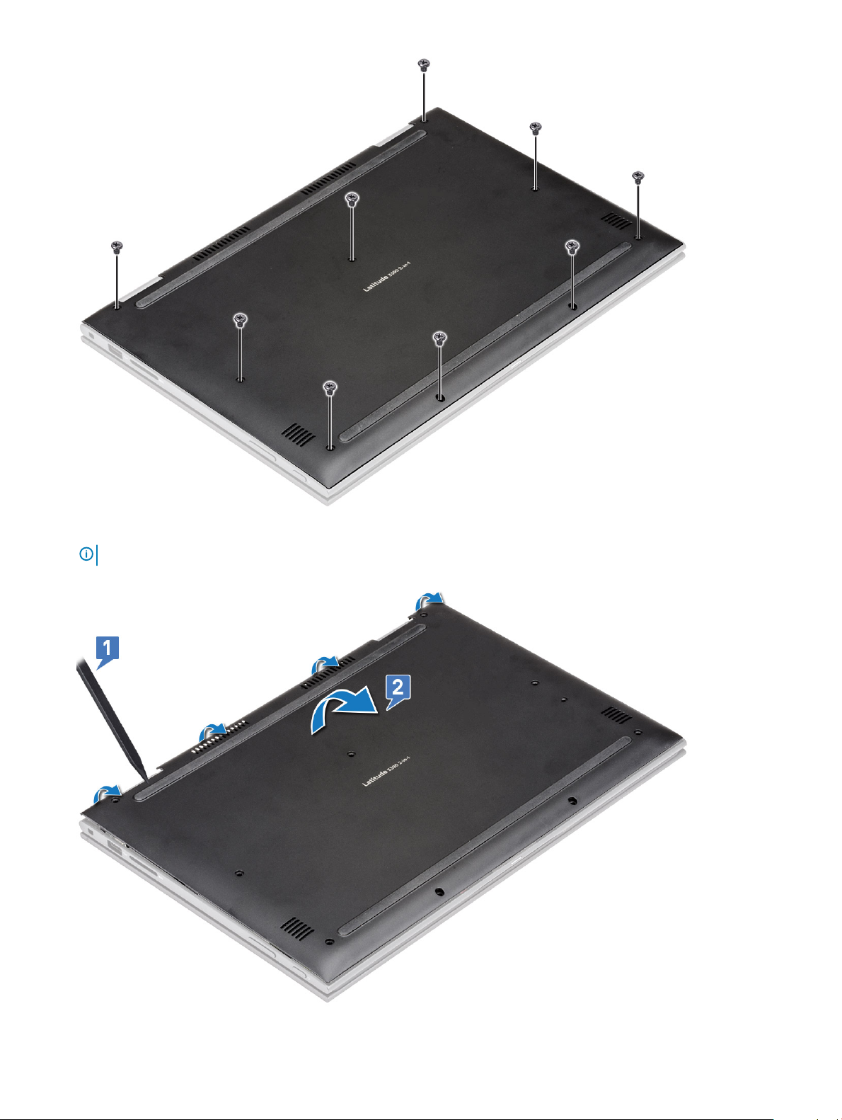
4 Using a plastic scribe, pry the base cover from the edges of the laptop chassis [1].
NOTE
: Pry the edges clockwise, starting from the lower left side of the air vent.
10 Removing and installing components
Page 11
5 Lift the base cover away from the laptop [2].
Installing the base cover
1 Align the edges of the base cover with the laptop and press until it clicks into place.
2 Tighten the screws to secure the base cover to the laptop.
3 Follow the procedure in After working inside your computer.
Battery
Removing the battery
1 Follow the procedure in Before working inside your computer.
2 Remove the base cover.
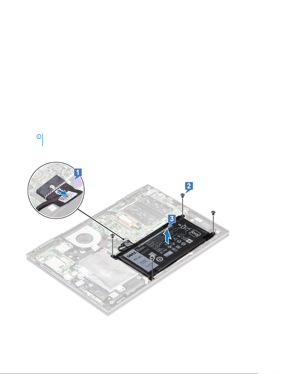
3 To remove the battery:
a Disconnect the battery cable from the connector on the system board [1].
NOTE: Ensure to pull the battery cable from the connector by the head of the connector label, to avoid damage to the
PIN.
b Remove the M2x3 screws (4) that secure the battery to the laptop [2].
c Lift the battery away from the laptop [3].
Removing and installing components
11
Page 12

Installing the battery
1 Insert the battery into the slot on the laptop.
2 Tighten the M2x3 screws (4) to secure the battery to the laptop.
3 Connect the battery cable to the connector on the system board
4 Install the base cover.
5 Follow the procedure in After working inside your computer.
Power and volume control board
Removing the power and volume control board
1 Follow the procedure in Before working inside your computer.
2 Remove the:
a base cover
b battery
c coin cell battery
3 To remove the power and volume control board:
a Disconnect the power cable from the connector on the system board [1].
CAUTION
battery cable.
b Peel the adhesive tape [2].
c Release the volume control board cable from the routing clips .
d Remove the M2x3 screw (1) that secures the power and volume control board to the laptop [3].
e Lift the power and volume control board away from the laptop [4].
: Ensure that you remove the coin cell battery connector on the system board, to avoid damage to the
12
Removing and installing components
Page 13
Installing the power and volume control board
1 Place the power and volume control board on the laptop chassis.
NOTE
: Place the power and volume control board into the two plastic placeholders which secures the board to the system
chassis.
2 Tighten the M2x3 screw (1) to secure the power and volume control board to the laptop.
3 Route the cables through the cable routing clips.
4 Connect the power and volume control board to the connector on the system board.
5 Ax the adhesive tape to secure it.
6 Install the:
a coin cell battery
b battery
c base cover
7 Follow the procedure in After working inside your computer.
Removing and installing components
13
Page 14
Hard disk drive (HDD)
Removing the HDD
1 Follow the procedure in Before working inside your computer.
2 Remove the:
a base cover
b battery
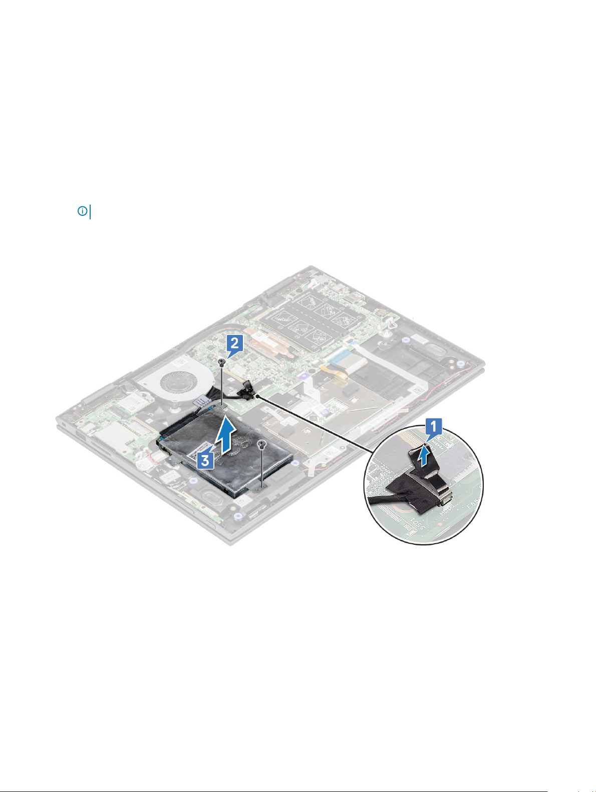
3 To remove the HDD:
a Disconnect the HHD cable from the connector on the system board [1].
NOTE: Ensure to pull the HDD cable by the plastic handle to avoid damage to the connector and cable.
b Release the cable adhesive tape that secures the cable to the system board.
c Remove the M2.5x6 screw (2) that secures the HDD on the laptop system board [2].
d Lift the HDD from the system board [3].
Installing the HDD
1 Place the HDD on the hard disk placeholder.
2 Press the adhesive tape to secure the HDD cable.
3 Connect the HDD cable head to the connector on the system board.
4 Tighten the M2.5x6 screw (2) to secure the HDD to the laptop chassis.
5 Install the:
a battery
b base cover
6 Follow the procedure in After working inside your computer.
Removing and installing components
14
Page 15
Coin cell battery
Removing the coin cell battery
1 Follow the procedure in Before working inside your computer.
2 Remove the:
a base cover
b battery
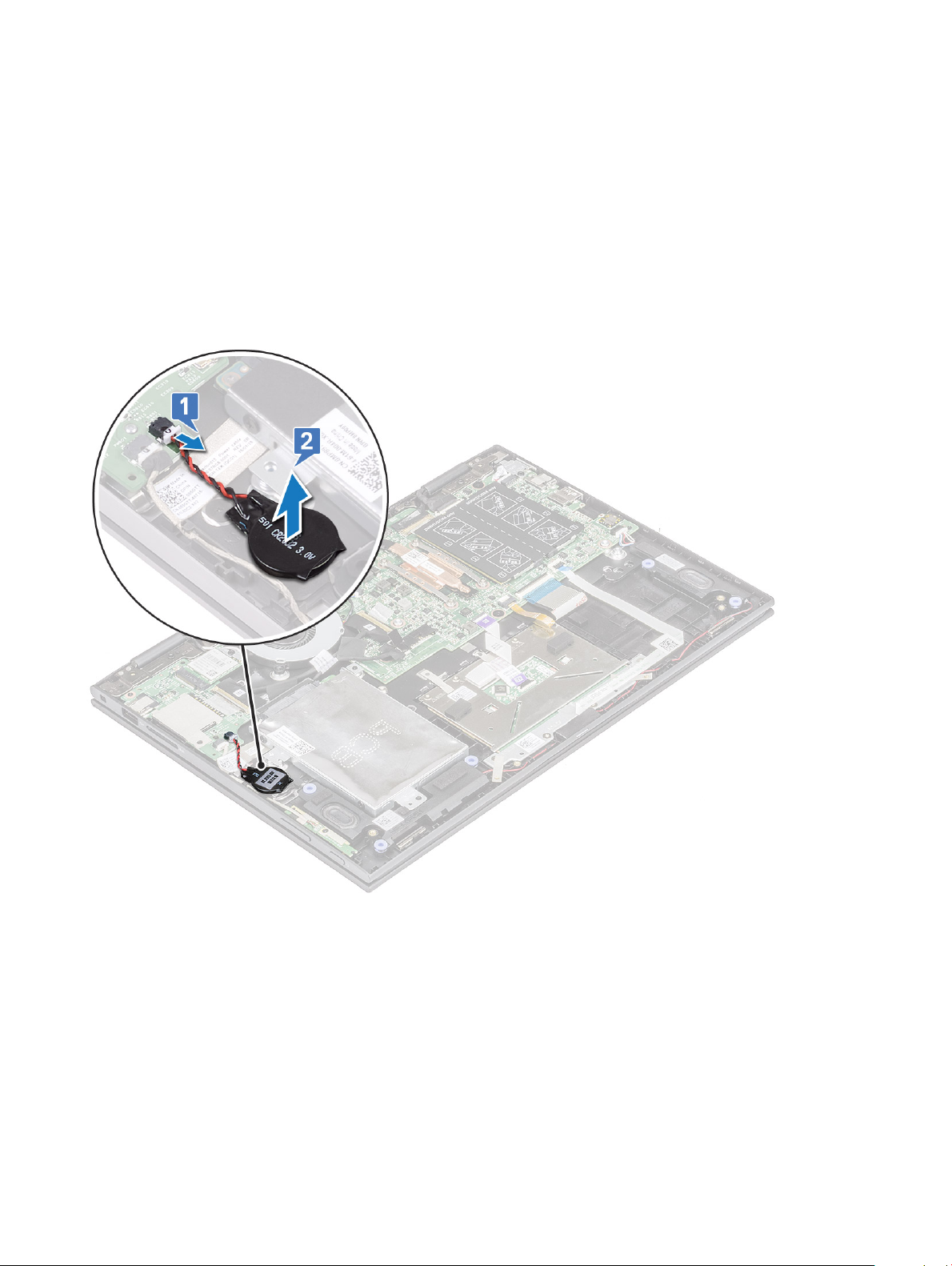
3 To remove the coin cell battery:
a Disconnect the coin cell battery from the connector on the system board [1].
b Pry and lift the coin cell battery to release it from the adhesive on the laptop [2].
Installing the coin cell battery
1 Place the coin cell battery on the laptop.
2 Connect the coin cell battery cable to the connector on the system board.
3 Install the:
a battery
b base cover
4 Follow the procedure in After working inside your computer.
Removing and installing components
15
Page 16
WLAN card
Removing the WLAN card
1 Follow the procedure in Before working inside your computer.
2 Remove the:
a base cover
b battery
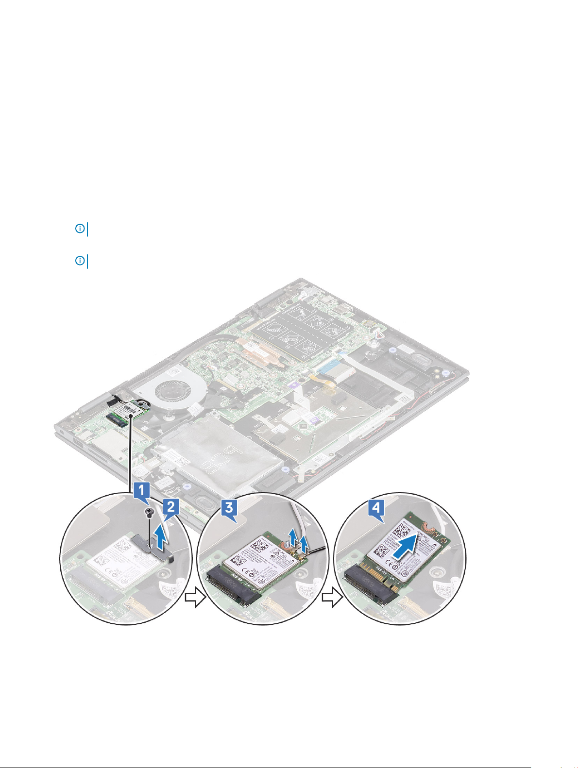
3 To remove WLAN card:
a Remove the M2x3 screw (1) that secures the WLAN card to the laptop [1].
b Lift the metal bracket to access the WLAN cables [2].
c Disconnect the WLAN cables from the connectors on the WLAN card [3].
NOTE: Ensure to gently use plastic scribe to disconnect the WLAN cables from the connectors.
d Slide the WLAN card away from the connector on the system board [4].
NOTE: Ensure to lift the WLAN card by an angle NOT more than 35°
16 Removing and installing components
Page 17
Installing the WLAN
1 Slide and connect the WLAN card to the connector on the system board.
2 Connect the WLAN cables to the connectors on the WLAN card.
3 Place the metal bracket to secure the WLAN cables.
4 Tighten the M2x3 screw (1) to secure the WLAN card to the laptop.
5 Install the:
a battery
b base cover
6 Follow the procedure in After working inside your computer.
Memory modules
Removing the memory module
1 Follow the procedure in Before working inside your computer.
2 Remove the:
a base cover
b battery
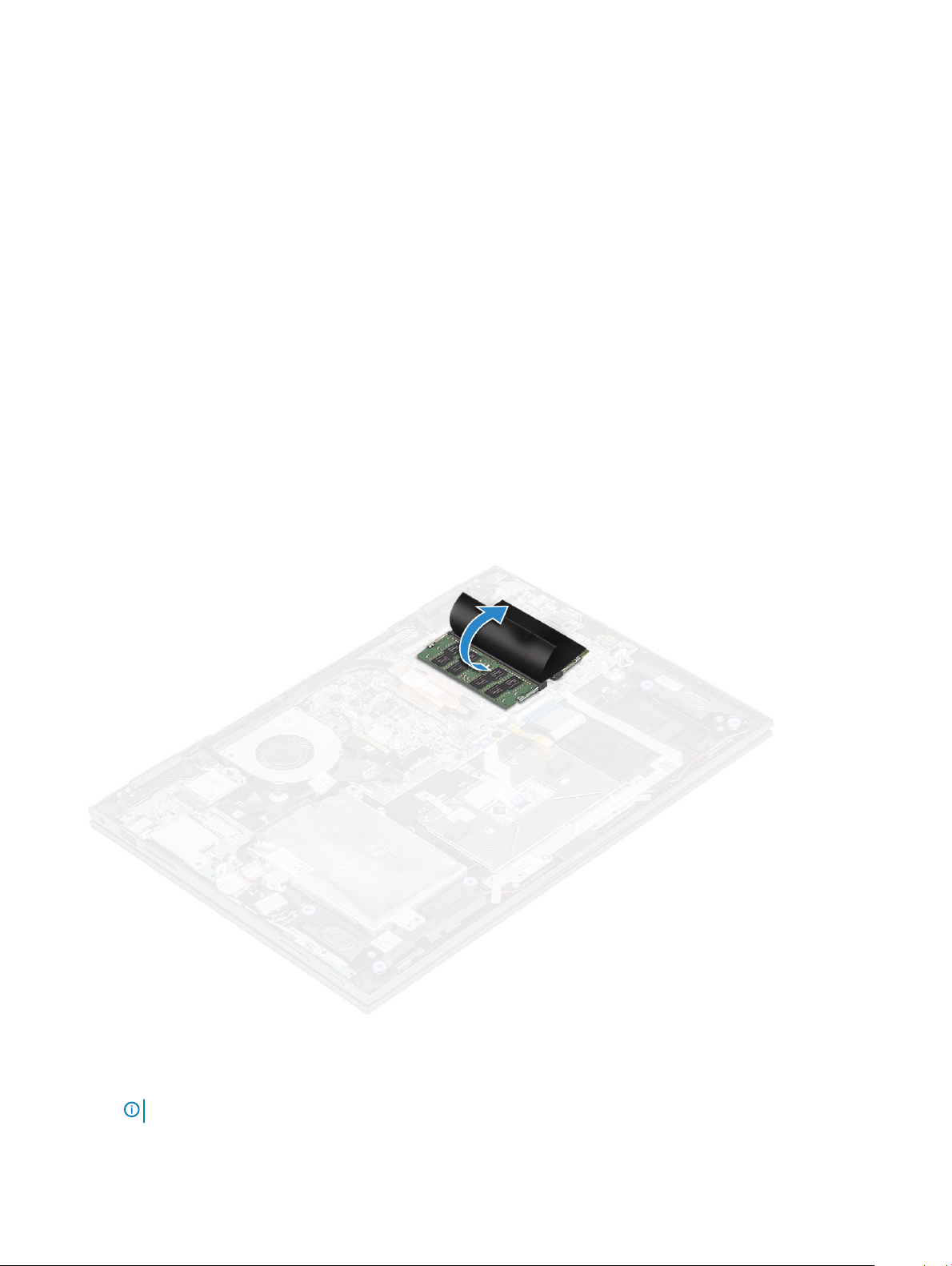
3 Peel and hold the label that protects the memory module to the laptop.
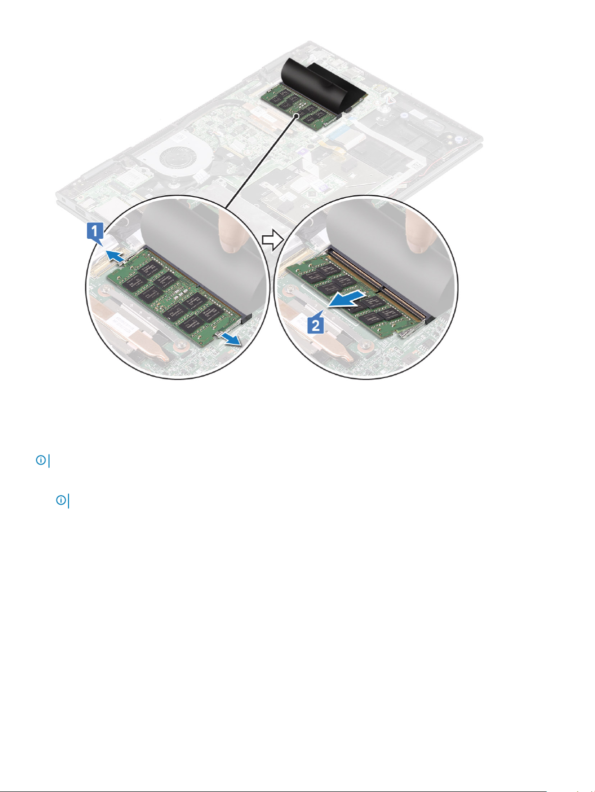
4 To remove memory module:
a Pull the retention clips away from the memory module until the memory module pops out [1].
b Pull the memory module from the memory module socket on the system board [2].
: Ensure to lift the memory module card by an angle NOT more than 35°.
NOTE
Removing and installing components 17
Page 18
5 Repeat steps 3 and 4 to remove the second memory module (if available or shipped with the system).
Installing the memory module
: Install the second memory module with DRAM chips facing downward.
NOTE
1 Insert the memory module into the memory module socket until the retention clips secure the memory module.
NOTE
: Ensure to hear a click sound when the memory module is secured.
2 Ax the adhesive tape to secure the memory moduleRelease the label that protects the memory module.
3 Install the:
a battery
b base cover
4 Follow the procedure in After working inside your computer.
System fan
Removing the system fan
1 Follow the procedure in Before working inside your computer.
2 Remove the:
a base cover
b battery
Removing and installing components
18
Page 19
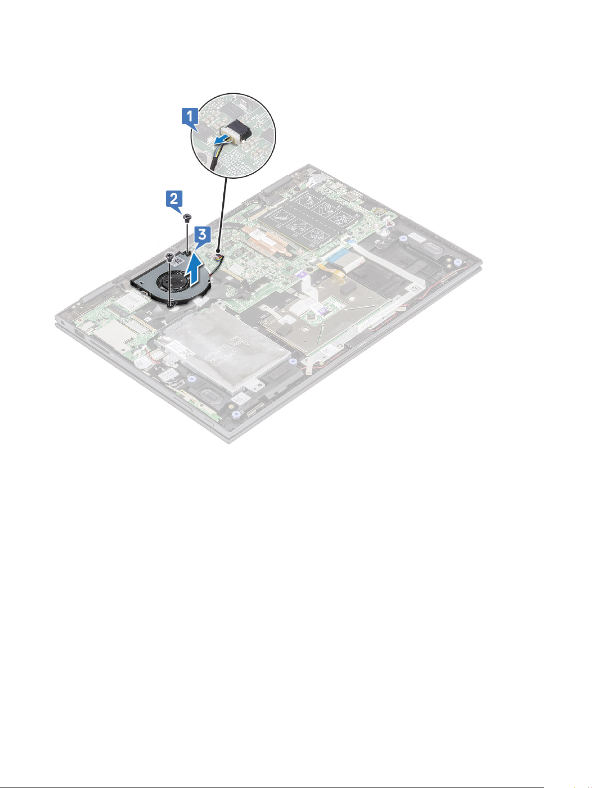
3 To remove the system fan:
a Disconnect the system fan cable from the connector on the system board [1].
b Remove the M2x3 screws (2) that secure the system fan to the laptop [2].
c Lift the system fan away from the laptop [3].
Installing the system fan
1 Place the system fan on the laptop.
2 Tighten the M2x3 screws (2) to secure the system fan to the laptop.
3 Connect the system fan cable to the connector on the system board.
4 Install the:
a battery
b base cover
5 Follow the procedure in After working inside your computer.
Heat sink
Removing the heat sink
1 Follow the procedure in Before working inside your computer.
2 Remove the:
Removing and installing components
19
Page 20
a base cover
b battery
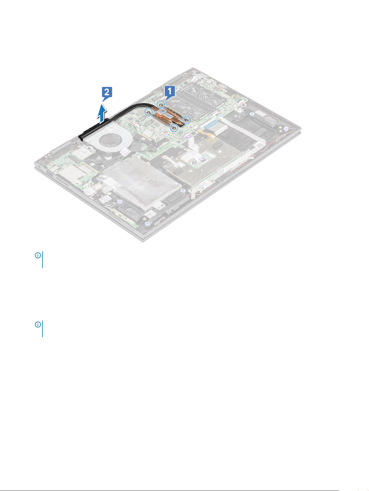
3 To remove the heat sink:
a Loosen the captive screws that secure the heat sink to the laptop[1] .
b Lift the heat sink away from the laptop [2].
NOTE: Loosen the captive screws using a diagonal or crisscross pattern as printed on Heatsink. The screws are captive
screws and cannot be fully removed.
Installing the heat sink
1 Place the heat sink on the system board.
2 Tighten the captive screws to secure the heat sink to the laptop.
NOTE
: Tighten the screws using a diagonal or crisscross pattern as printed on Heatsink. The screws are captive screws and
cannot be fully removed.
3 Install the:
a battery
b base cover
4 Follow the procedure in After working inside your computer.
LED board
Removing the LED board
1 Follow the procedure in Before working inside your computer.
2 Remove the:
Removing and installing components
20
Page 21
a base cover
b battery
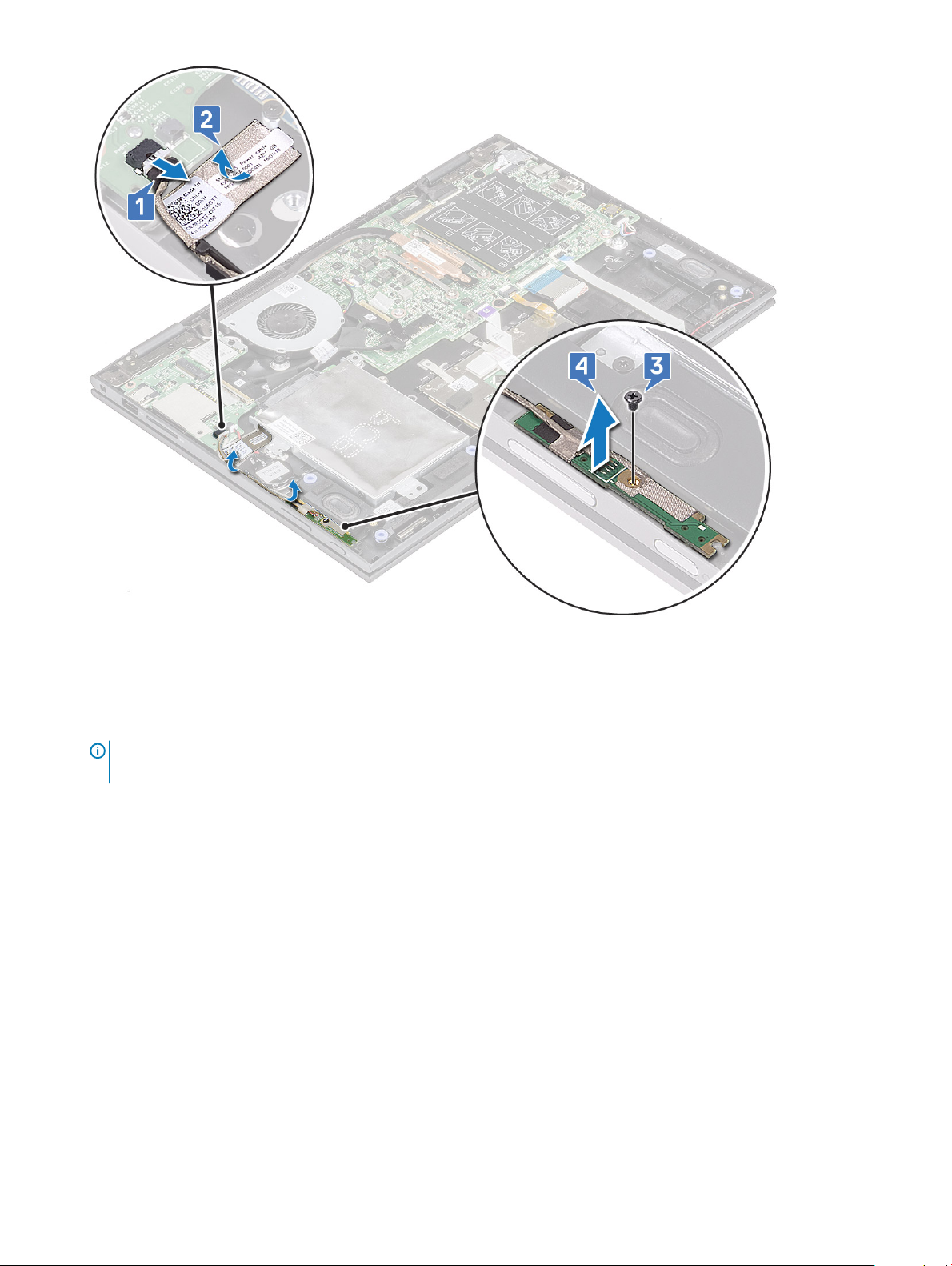
3 To remove the LED board:
a Lift the latch and disconnect the LED board cable [1].
NOTE: Use a sharp tool or a plastic scribe to gently lift the latch.
b Release the LED board cable from the laptop [2].
NOTE: LED board cable is glued with a adhesive,ensure to peel gently to avoid damage.
c Peel the adhesive tape to access the LED board [3].
d Lift the LED board away from the laptop .
NOTE
: The LED board is secured on a cylindrical plastic hook. Ensure to lift the board without a damage to the LED
board hole, that secures it on the system board.
Removing and installing components 21
Page 22
Installing the LED board
1 Insert the LED board into the slot on the laptop.
NOTE
: Ensure to align the LED board hole to the cylindrical hook to secure the board on the system board.
2 Ax the adhesive tape to secure the LED board to the laptop.
3 Ax the LED board cable to the adhesive tape on the system board and connect the LED board cable to the connector.Release the
latch.
4 Install the:
a battery
b base cover
5 Follow the procedure in After working inside your computer.
Speaker
Removing the speakers
1 Follow the procedure in Before working inside your computer.
2 Remove the:
a base cover
b battery
c LED board
3 To remove speakers:
a Remove the mylar tape that secures the speaker cable on the system board [1].
: Lift the latch and release the LED board cable from the laptop, before un-routing the speaker cable.
NOTE
b Disconnect the speaker cable from the connector on the system board [2].
Removing and installing components
22
Page 23
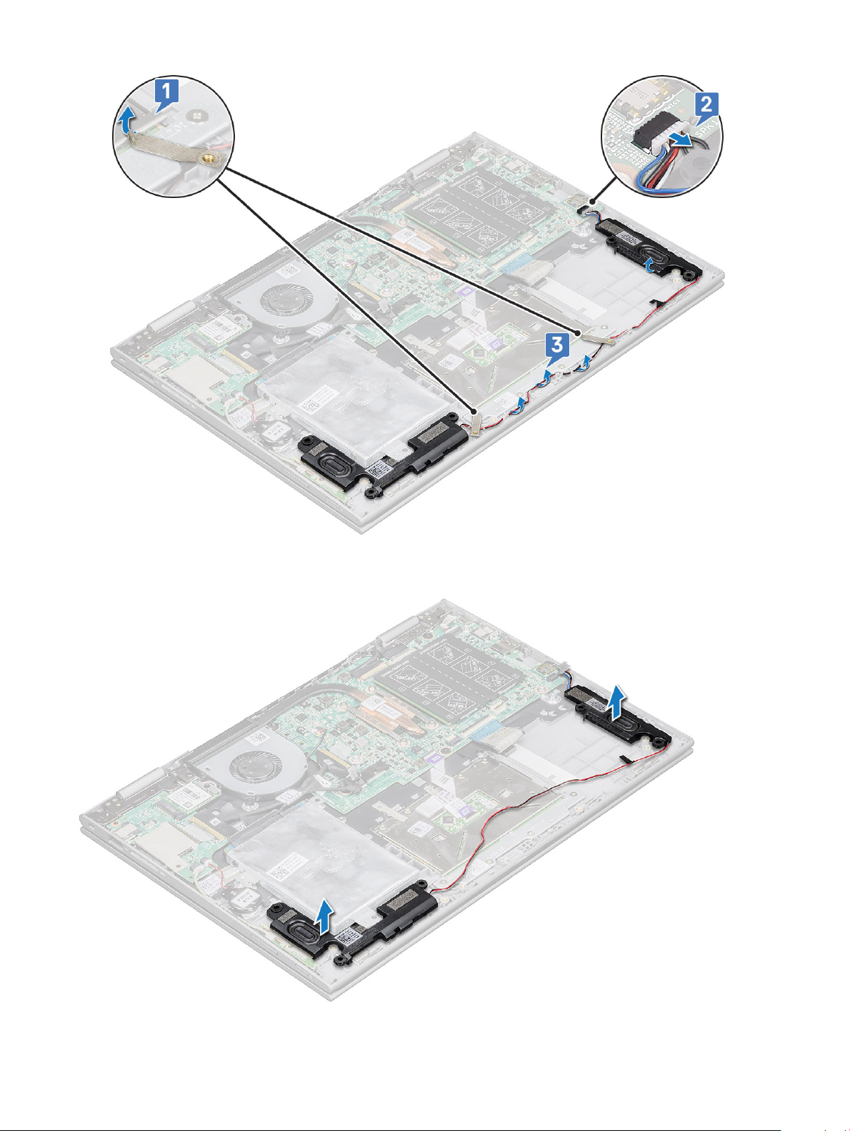
c Release the speaker cables from the routing clips on the system board [3].
d Lift the speakers away from the laptop.
•
Removing and installing components
23
Page 24

Installing the speakers
1 Insert the speakers into the slot on the laptop.
2 Route the speaker cable through the cable routing clips.
3 Paste the Mylar tape to secure the speaker cable on the system board.
4 Connect the speaker cable to the connector on the system board.
5 Install the:
a LED board
b battery
c base cover
6 Follow the procedure in After working inside your computer.
Input/Output(I/O) boards
Removing the Input-Output board
1 Follow the procedure in Before working inside your computer.
2 Remove the:
a base cover
b battery
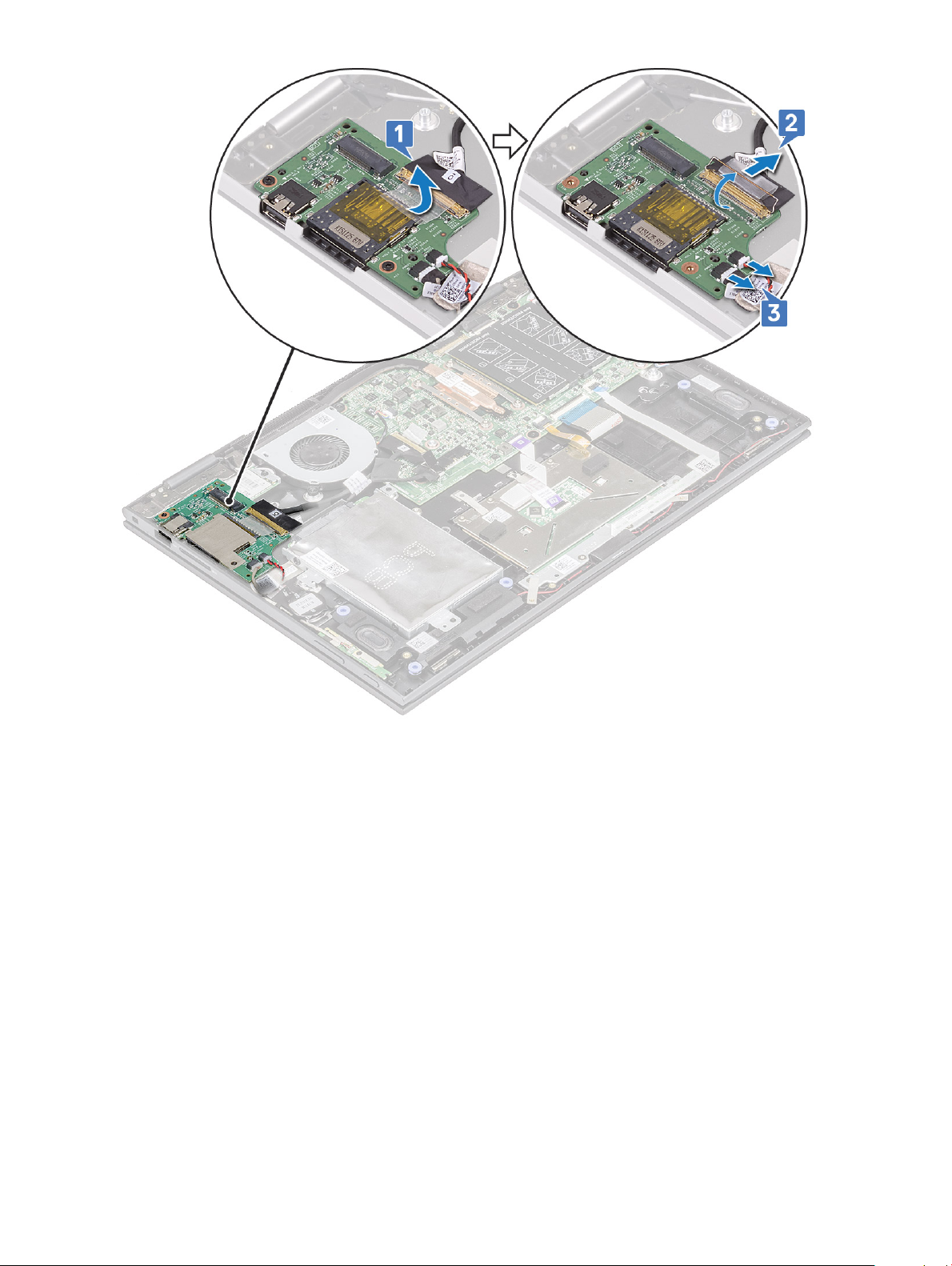
3 To remove the I/O board:
a Peel and lift the plastic label of the I/O board cable [1].
b Pull the copper lever to disconnect the I/O board cable on the system board [2].
NOTE
: Ensure to pull the copper lever by an angle 15° to 20°, to avoid damage to the connector copper pins.
c Disconnect the coin cell battery and power and volume button board cables from the I/O board [3].
24
Removing and installing components
Page 25
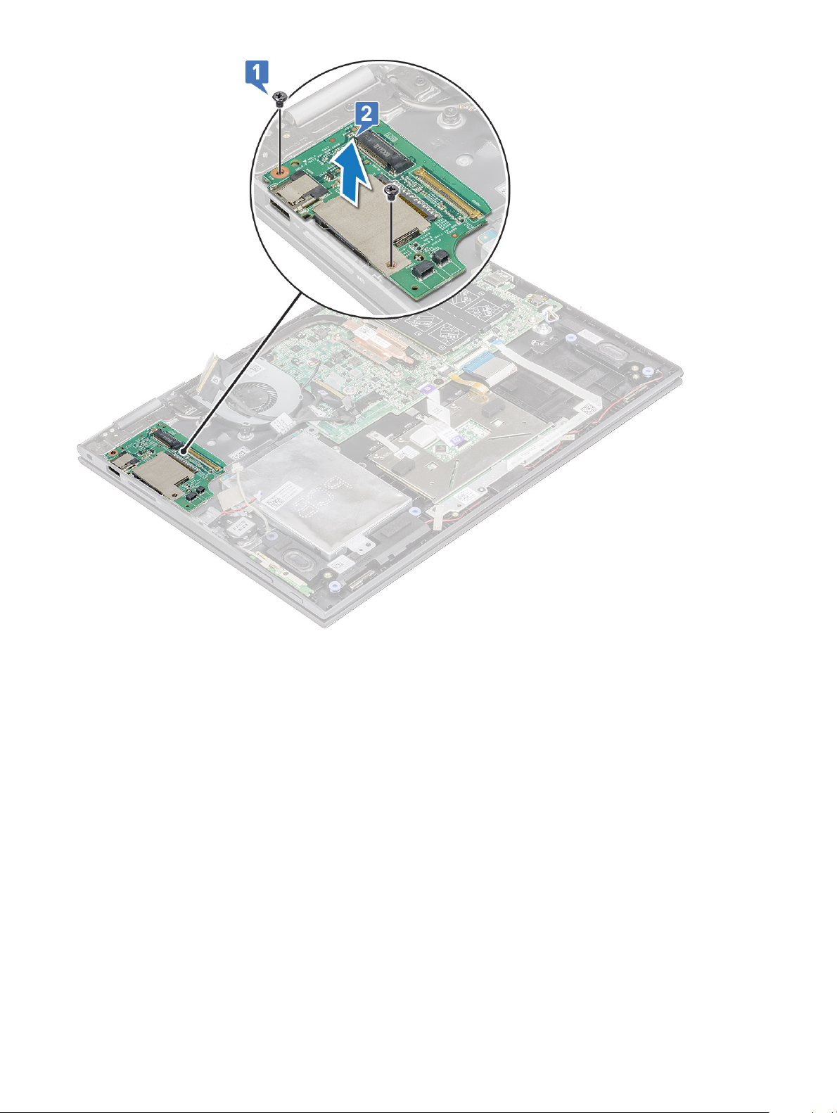
d Remove the M2x3.5 screw (2) that secures the I/O board to the laptop chassis [1].
e Lift the I/O board from the laptop chassis [2].
Removing and installing components
25
Page 26
Installing the Input-Output board
1 Place the I/O board on the laptop.
2 Tighten the M2x3.5 screws (2) to secure the I/O board to the laptop.
3 Connect the coin cell battery and power and volume button board cables to the connector on the I/O board.
4 Connect the I/O board cable to the connector on the system board.
5 Ax the adhesive tape to secure the I/O board cable and release the copper latch.
6 Install the:
a battery
b base cover
7 Follow the procedure in After working inside your computer.
Removing and installing components
26
Page 27
Touchpad buttons board
Removing the touchpad
1 Follow the procedure in Before working inside your computer.
2 Remove the:
a base cover
b battery
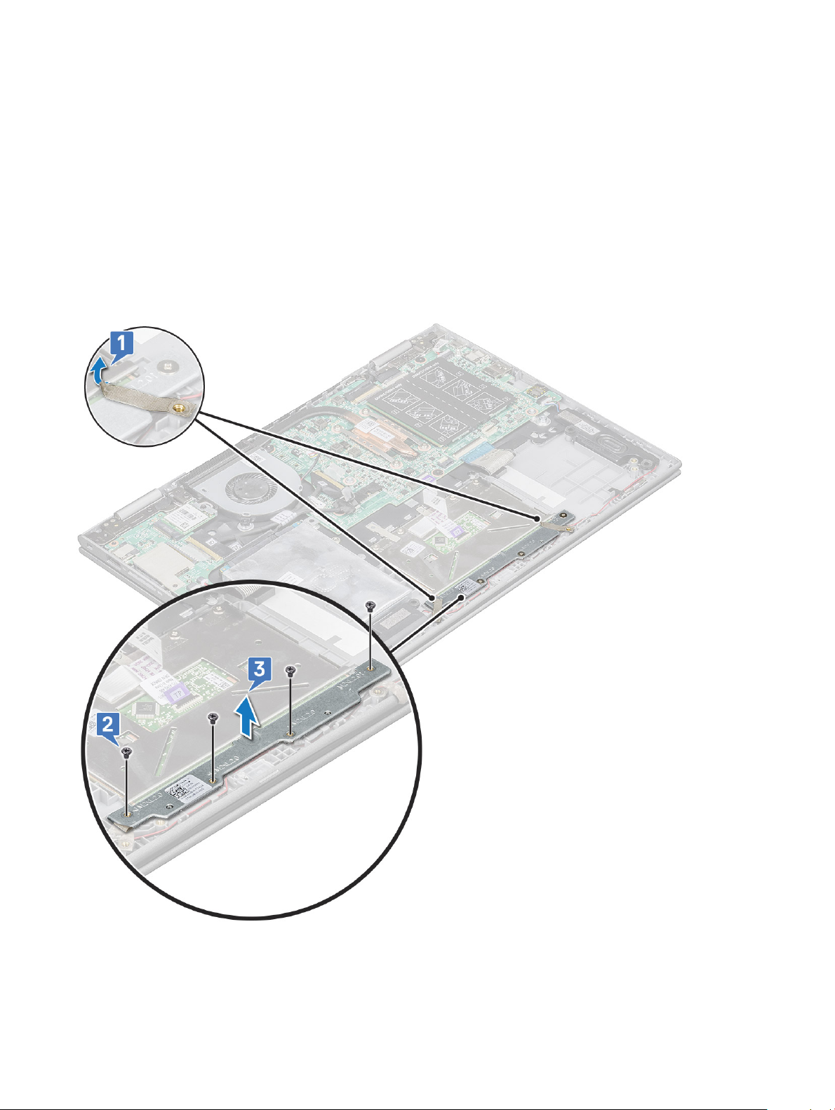
3 To remove the touchpad metal bracket:
a Remove the mylar tapes that secures the speaker cable to the laptop [1].
b Remove the M2x2 screws (4) that secure the touchpad board to the laptop chassis [2].
c Lift the touchpad metal bracket from the laptop chassis [3].
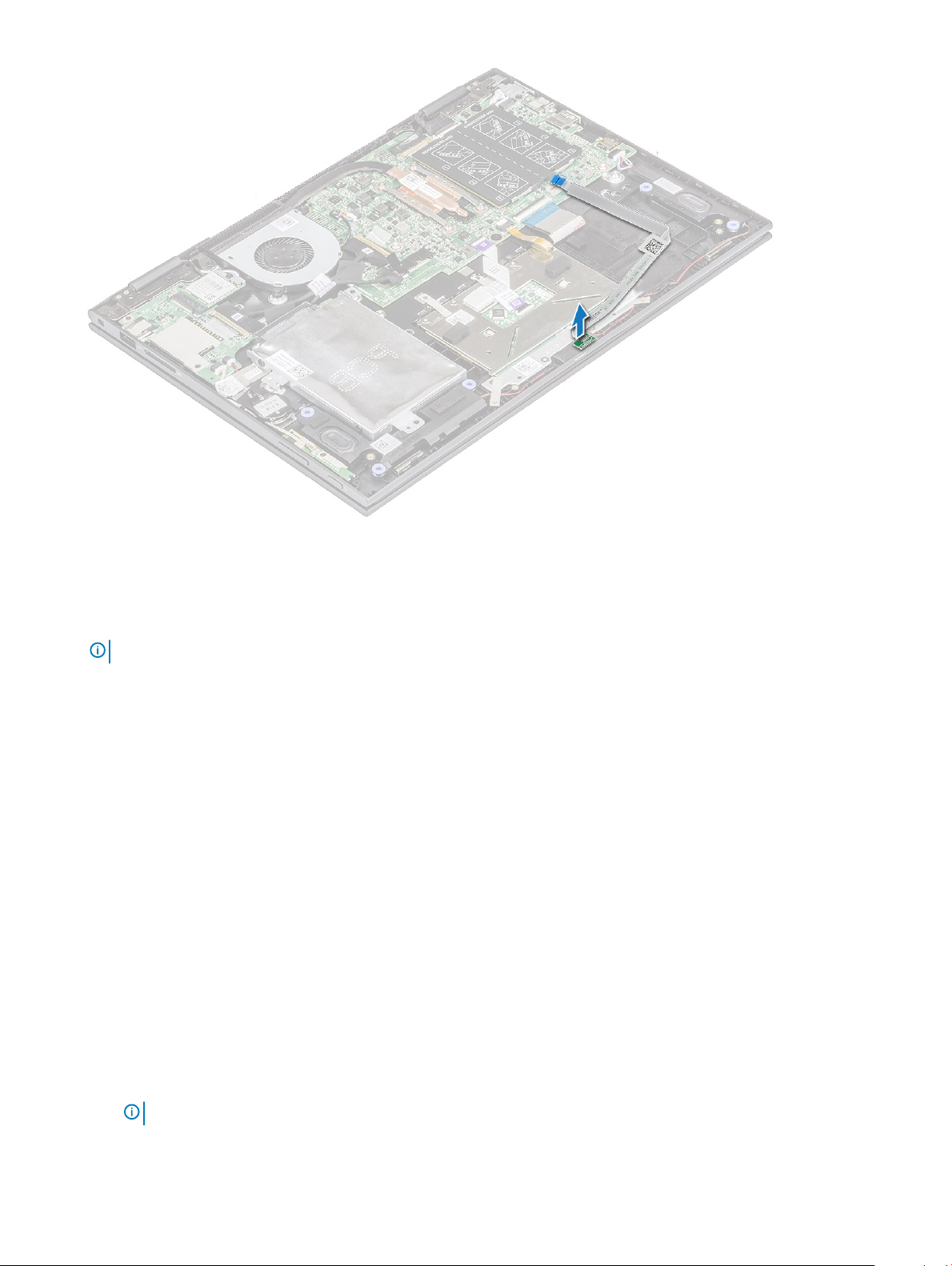
4 To release the touchpad:
a Remove the mylar tapes that secure the touchpad bracket to the laptop [1]
b Lift the latch and release touchpad cable on the system board [2].
c Pull the touchpad cable to release it from adhesive that secure the cable to the laptop.
Removing and installing components
27
Page 28

5 To remove touchpad board:
a Remove the M2x2 screws (4) that secure the touchpad to the laptop [1].
b Lift the touchpad away from the laptop chassis [2].
28
Removing and installing components
Page 29

Installing the touchpad
1 Place the touchpad on the laptop.
2 Tighten the screws to secure the touchpad to the laptop.
3 Place the metal tab over the touchpad.
4 Tighten the screws to secure the metal tab.
5 Connect the touchpad cable and keyboard daughter board cable to the connectors on the system board.
6 Install the:
a battery
b base cover
7 Follow the procedure in After working inside your computer.
Display assembly
Removing the display assembly
1 Follow the procedure in Before working inside your computer.
2 Remove the:
a base cover
b battery
c WLAN card
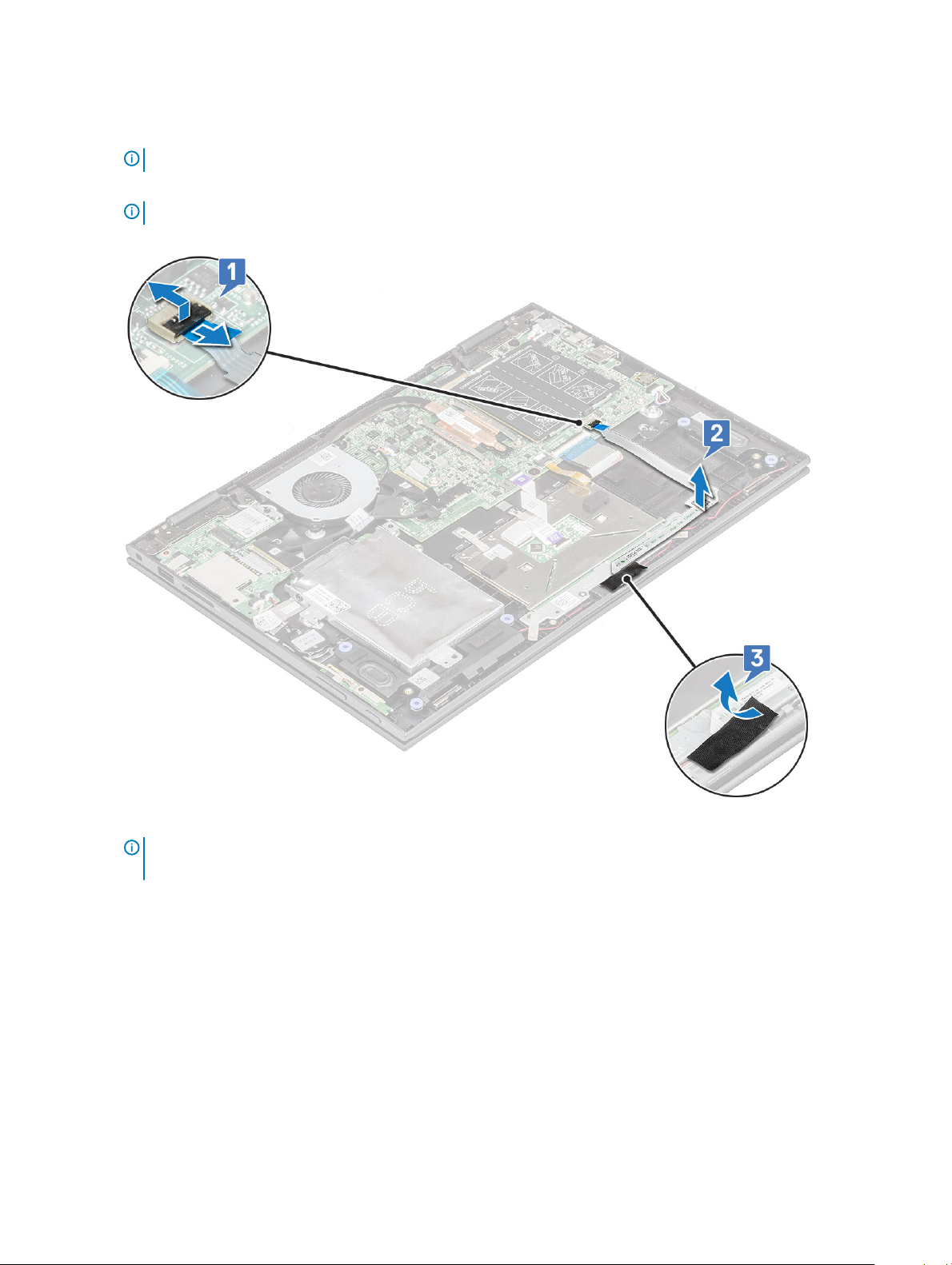
3 To release the display assembly:
a Peel the adhesive tapes that secure the display cable and touch screen board cables [1] [2].
b Open the latches and disconnect the display and touch screen board cables from the system board [3] [4].
Removing and installing components
29
Page 30

4 Turn the computer over and open the display.
5 To remove display assembly:
a Remove the screws that secure the display assembly to the laptop chassis [1].
b Lift the display assembly away from the laptop chassis [2].
30 Removing and installing components
Page 31

Installing the display assembly
1 Align the display assembly with the screw holders on the laptop chassis.
2 Tighten the screw to secure the display assembly to the laptop chassis.
3 Close the display and turn the laptop over.
4 Connect the display and touch screen board cables to the connectors on the system board.
5 Ax the adhesive tapes to secure the display and touch screen board cables.
6 Install the:
a WLAN card
b battery
c base cover
7 Follow the procedure in After working inside your computer.
Display cover
Removing the display cover
1 Follow the procedure in Before working inside your computer.
2 Remove the:
a base cover
b battery
c display assembly
3 To remove the display cover:
Removing and installing components
31
Page 32

a Using a plastic scribe, pry the display cover from the edges to release it from the display assembly [1].
b Lift the display cover away from the display assembly [2].
NOTE: Apply pressure uniformly in all sides of the display cover to avoid damaging the clips.
c Release the display cable and touch screen board cable from under the display hinge [3].
32 Removing and installing components
Page 33

Installing the display cover
1 Route the display cable and touch screen board cable to the display hinge.
2 Place the display cover on the display assembly and press along the edges to secure it.
3 Install the:
a display assembly
b battery
c base cover
4 Follow the procedure in After working inside your computer.
Camera
Removing the camera
1 Follow the procedure in Before working inside your computer.
2 Remove the:
a base cover
b battery
c display assembly
d display cover
3 To remove the camera:
a Using a plastic scribe, release the camera module from the display panel [1] [2].
b Disconnect the camera cable from the camera module [3].
Removing and installing components
33
Page 34

Installing the camera
1 Connect the camera cable to the connector on the camera module.
2 Insert the camera module into the slot on the display panel.
3 Install the:
a display cover
b display assembly
c battery
d base cover
4 Follow the procedure in After working inside your computer.
Display (eDP) cable
Removing the display cable
1 Follow the procedure in Before working inside your computer.
2 Remove the:
a base cover
b battery
c display assembly
d display cover
Removing and installing components
34
Page 35

3 To remove the display cable:
a Peel the adhesive tape and pull the latch to release the cables [1].
NOTE: Remove the tape cautiously for reuse.
b Disconnect the sensor board cable and the display cable from the display panel [2].
c Lift the display cable away from the display panel [3].
Installing the display cable
1 Route the display cable through the placeholders on the display panel.
2 Align the display cable along the routing channels on the display panel.
3 Connect the display cable and sensor board cable to the connectors on the display panel.
4 Ax the adhesive tapes to secure the display cable and sensor board cable.
5 Install the:
a display cover
b display assembly
c battery
d base cover
6 Follow the procedure in After working inside your computer.
Removing and installing components
35
Page 36

Power connector port
Removing the power connector port
1 Follow the procedure in Before working inside your computer.
2 Remove the:
a base cover
b battery
3 To remove the power connector port:
a Disconnect the power connector port cable from the connector on the system board [1].
b Remove the M2x3 screw (1) that secures the power connector port to the laptop [2].
c Lift the power connector port away from the laptop [3].
Installing the power connector port
1 Insert the power connector port into the slot on the laptop.
2 Tighten the M2x3 screw (1) to secure the power connector port to the laptop.
3 Connect the power connector port cable to the connector on the system board.
Removing and installing components
36
Page 37

4 Install the:
a battery
b base cover
5 Follow the procedure in After working inside your computer.
System board
Removing the system board
1 Follow the procedure in Before working inside your computer.
2 Remove the:
a base cover
b battery
c hard disk
d memory module
e coin cell battery
f WLAN card
g system fan
h heat sink
3 To disconnect the following cables from the system board:
a Lift the latch and disconnect the touch screen cable and display cable [1].
b Pull the plastic label and release the I/O board cable on the system board [2].
c Pull the label to disconnect the HDD cable on the system board [3]
d Lift the latch and release the touchpad cable [4].
e Disconnect the keyboard back lid cable [5].
f Lift the latch and release the keyboard cable [6].
g Lift the latch and release the LED cable [7]
h Disconnect the speaker cable on the system board [8].
i Disconnect the power connector port cable on the system board [9].
Removing and installing components
37
Page 38

j Remove the metal bracket screws (2) that secures the USB Type-C to the system board [1].
k Lift the metal bracket from the system board [2].
38
Removing and installing components
Page 39

4 To remove the system board:
a Remove the screws (3) that secure the system board to the laptop [1].
b Lift the system board away from the laptop[2].
Removing and installing components
39
Page 40

Installing the system board
1 Place the system board on the laptop.
2 Tighten the screws to secure the system board to the laptop.
3 Connect the following cables to the connectors on the system board:
a display cable
b keyboard cable
c touch pad cable
d power connector port
e HDD cable
f speaker cable
g LED cable
h keyboard back lid cable
i I/O board cable
4 Place the metal bracket and ax the screws (2) that secures the USB Type-C to the system board.
5 Ax the adhesive tapes to secure the I/O board, display, and touch screen cables.
6 Install the:
a heat sink
b system fan
c WLAN card
d coin cell battery
e memory module
f hard disk
g battery
h base cover
Removing and installing components
40
Page 41

7 Follow the procedure in After working inside your computer.
Palm rest
Removing the palmrest
1 Follow the procedure in Before working inside your computer.
2 Remove the:
a base cover
b battery
c WLAN card
d power and volume control board
e memory module
f hard disk
g coin cell battery
h system fan
i touchpad
j heat sink
k I/O board
l LED board
m power connector port
n display assembly
o speakers
p system board
The palmrest is the last component, after removing all the components.
Removing and installing components
41
Page 42

Installing the palmrest
1 Place the palmrest on a at surface.
2 Install the:
a system board
b speakers
c display assembly
d power connector port
e I/O board
f LED board
g heat sink
h touchpad
i system fan
j coin cell battery
k hard disk
l WLAN card
m memory module
n power and volume control board
o battery
p base cover
3 Follow the procedure in After working inside your computer.
42
Removing and installing components
Page 43

Technology and components
Power adapter
This laptop is shipped with the 45 W power adapter. This adapter uses an E4 connector.
WARNING: When you disconnect the power adapter cable from the laptop, grasp the connector, not the cable itself, and then
pull rmly but gently to avoid damaging the cable.
WARNING: The power adapter works with electrical outlets worldwide. However, power connectors and power strips vary
among countries. Using an incompatible cable or improperly connecting the cable to the power strip or electrical outlet may
cause re or equipment damage.
Processors
This laptop is shipped with the following processors:
• Intel Pentium-4405U
• Intel Core i3-6100U
• Intel Core i5-6200U
• Intel Core i5-6300U
3
: The clock speed and performance varies depending on the workload and other variables.
NOTE
Skylake processor
Intel Skylake is the successor to the Intel® Broadwell processor. It is a microarchitecture redesign using an already existing process
technology and it will be branded as Intel 6th Gen Core. Like Broadwell, Skylake is available in four variants with suxes SKL-Y, SKL-H, and
SKL-U.
The Skylake also includes Core i7, i5, i3, Pentium and Celeron processors.
Processor performance features
The following table illustrates the performance available on each Skylake.
Table 2. Performance features
Feature Feature description SKL-Y SKL-U SKL-H
General Features Cores Dual Core Dual Core Dual Core
CPU/Memory/Graphic
Overclocking
Intel Extreme Tuning
Utility
No No Yes
No No Yes
Intel Hyper-Threading
Technology
Yes Yes Yes
Technology and components 43
Page 44

Feature Feature description SKL-Y SKL-U SKL-H
Intel Smart Cache
Technology with last level
cache (LLC) sharing
between Processor and
GFx cores
Intel Smart Sound
Technology
Intel Turbo Boost
Technology 2.0
Last Level Cache (LLC) Up to 4M Up to 4M Up to 4M
Voltage Optimizer Yes TBD TBD
Display 3 Independent Display
Support
HDMI 2.0 Display @60Hz 3840x2160 3840x2160 3840x2160
DP/eDP Display @60Hz 3840x2160 4096x2304 4096x2304
eDP 1.3, support for
MPO, NV12
Media Intel Built-In Visuals Yes Yes Yes
Compute OpenCL 2.0 Yes No yes
Yes Yes Yes
Yes Yes Yes
Yes Yes Yes
Yes Yes Yes
Yes Yes Yes
Platform
Hardware
Memory Memory Type
14nm process Yes Yes Yes
16PCIe Graphic lanes
(congurable as 1x16 or
2x8 or 1x8+2x4)
PCIe Gen3.0 support No No Yes
Switchable graphics
(muxless solution)
Connector / Memory
Down
Speed
Max Capacity
No No Yes
No Yes Yes
• LPDDR3
• DDR3L
Memory down SODIMM SODIMM
• 1866MT/s for LPDDR3
• 1600MT/s for DDR3L
• LPDDR3–16 GB
• DDR3L-4 GB
• LPDDR3
• DDR3L
• DDR4
• 1866MT/s for LPDDR3
• 1600MT/s for DDR3L
• 2133MT/s for DDR4
• DDR3L-16 GB
• LPDDR3–16 GB
• DDR4=32 GB
• LPDDR3
• DDR3L
• DDR4
• 1866MT/s for LPDDR3
• 1600MT/s for DDR3L
• 2133MT/s for DDR4
• DDR3L-16 GB
• LPDDR3–16 GB
• DDR4=32 GB
OS Support Windows 10 (64-bit) Yes Yes Yes
Windows 7 (64-bit /
32bit)
Windows 8.1 (64-bit) Yes Yes Yes
44 Technology and components
Yes Yes Yes
Page 45

Feature Feature description SKL-Y SKL-U SKL-H
Linux (kernel and
associated modules)
Chrome Yes Yes No
Android No No No
Yes Yes Yes
Identifying processors in Windows 10
1 Tap Search the Web and Windows.
2 Type Device Manager.
3 Tap Processor.
The processor information is displayed.
Verifying the processor usage in Task Manager
1 Right Click on the taskbar.
2 Select Start Task Manager.
The Windows Task Manager window is displayed.
3 Click the Performance tab in the Windows Task Manager window.
The processor performance details are displayed.
Verifying the processor usage in Resource Monitor
1 Right Click on the taskbar.
2 Select Start Task Manager.
The Windows Task Manager window is displayed.
3 Click the Performance tab in the Windows Task Manager window.
The processor performance details are displayed.
Technology and components
45
Page 46

4 Click Open Resource Monitor.
Downloading the chipset driver
1 Turn on the laptop.
2 Go to Dell.com/support.
3 Click Product Support, enter the Service Tag of your laptop, and then click Submit.
NOTE
: If you do not have the Service Tag, use the autodetect feature or manually browse for your laptop model.
4 Click Drivers and Downloads.
5 Select the operating system installed on your laptop.
6 Scroll down the page, expand Chipset, and select your chipset driver.
7 Click Download File to download the latest version of the chipset driver for your laptop.
8 After the download is complete, navigate to the folder where you saved the driver le.
9 Double-click the chipset driver le icon and follow the instructions on the screen.
Chipsets
All laptops or notebook communicate with the CPU through the chipset. This laptop is shipped with the Intel Mobile CM238 .
Identifying the chipset in Device Manager on Windows 10
1 Right click the Start Menu.
2 Select Device Manager.
3 Expand System Devices and search for the chipset.
Technology and components
46
Page 47

Graphic options
This laptop is shipped with the following graphics chipset options:
• Intel HD Graphics 510 – Intel Pentium
• Intel HD Graphics 520 – Intel Core i3/i5
Downloading drivers
1 Turn on the laptop.
2 Go to Dell.com/support.
3 Click Product Support, enter the Service Tag of your laptop, and then click Submit.
NOTE
: If you do not have the Service Tag, use the auto detect feature or manually browse for your laptop model.
4 Click Drivers and Downloads.
5 Select the operating system installed on your laptop.
6 Scroll down the page and select the graphic driver to install.
7 Click Download File to download the graphic driver for your laptop.
8 After the download is complete, navigate to the folder where you saved the graphic driver le.
9 Double-click the graphic driver le icon and follow the instructions on the screen.
Identifying the display adapter
1 Right Click the Start menu.
2 Select Device Manager.
3 Expand Display adapters.
The display adapters are displayed.
Changing the screen resolution
1 Right click on the desktop and select Display Settings.
2 Tap or click Display settings.
The Setting window is displayed.
Technology and components
47
Page 48

3 Scroll down and select Advanced Display Settings.
The Advanced Display Setting is displayed.
4 Select the required resolution from the drop-down list and tap Apply.
Rotating the display
1 Right click on the desktop.
A sub menu is displayed.
2 Select Graphic Options > Rotation and choose one of the following:
• Rotate to Normal
• Rotate to 90 Degrees
• Rotate to 180 Degrees
• Rotate to 270 Degrees
: The Display can also be rotated using the following key combinations:
NOTE
• Ctrl + Alt + Up arrow key (Rotate to normal)
• Right arrow key (Rotate 90 degrees)
• Down arrow key (Rotate 180 degrees)
• Left arrow key (Rotate 270 degrees)
Display options
This laptop has 13.30– inch FHD with 1920 x 1080 resolution (maximum).
Adjusting brightness in Windows 10
To enable or disable automatic screen brightness adjustment:
1 Swipe-in from the right edge of the display to access the Action Center.
Tap or click All Settings > System > Display.
2
3 Use the Adjust my screen brightness automatically slider to enable or disable automatic-brightness adjustment.
: You can also use the Brightness level slider to adjust the brightness manually.
NOTE
48 Technology and components
Page 49

Cleaning the display
1 Check for any smudges or areas that must be cleaned.
2 Use a microber cloth to remove any obvious dust and gently brush o any dust particles.
3 Proper cleaning kits should be used to clean and keep your display in a crisp clear pristine condition.
NOTE: Never spray any cleaning solutions directly on the screen; spray it to the cleaning cloth.
Gently wipe the screen in a circular motion. Do not press hard on the cloth.
4
NOTE: Do not press hard or touch the screen with your ngers or you may leave oily prints and smears.
NOTE: Do not leave any liquid on the screen.
5 Remove all excess moisture as it may damage your screen.
6 Let the display dry thoroughly before you turn it on.
7 For stains that are hard to remove, repeat this procedure till the display is clean.
Using touch screen in Windows 10
Follow these steps to enable or disable the touch screen:
1 Right click on the Start menu.
2 Select Control Panel.
3 Tap Pen and Input Devices in the Control Panel.
4 Tap the Touch tab.
5 Select Use your nger as an input device to enable the touch screen. Clear the box to disable the touch screen.
Connecting to external display devices
Follow these steps to connect your laptop to an external display device:
1 Ensure that the external display device is turned on and plug the external display device cable into a video port on your laptop.
2 Press the Windows logo+P key.
3 Select one of the following modes:
• PC screen only
• Duplicate
• Extend
• Second Screen only
NOTE
: For more information, see the document that shipped with your display device.
Realtek ALC3253 Waves MaxxAudio Pro controller
This laptop is shipped with integrated Realtek ALC3253–CG Waves MaxxAudio Pro controller. It is a High Denition audio codec designed
for Windows desktop and laptops.
Downloading the audio driver
1 Turn on the laptop.
2 Go to www.Dell.com/support.
3 Click Product Support, enter the Service Tag of your laptop and click Submit.
Technology and components
49
Page 50

NOTE: If you do not have the Service Tag, use the autodetect feature or manually browse for your laptop model.
4 Click Drivers and Downloads.
5 Select the operating system installed on your laptop.
6 Scroll down the page and expand Audio.
7 Select the audio driver.
8 Click Download File to download the latest version of the audio driver for your laptop.
9 After the download is complete, navigate to the folder where you saved the audio driver le.
10 Double-click the audio driver le icon and follow the instructions on the screen.
Identifying the audio controller in Windows 10
1 Swipe from the right edge to access the Action center and select All Settings .
2 Type Device Manager in the search box and select Device Manager from the left pane.
3 Expand Sound, video and game controllers.
The audio controller is displayed.
Table 3. Identifying the audio controller in Windows 10
Before installation After installation
Changing the audio settings
1 Tap or touch the Search the web and Windows and type Dell Audio.
2 Start the Dell Audio utility from the left pane.
WLAN cards
This laptop supports the Intel Dual Band Wireless AC 7265 card
: Qualcomm xxxxxx (for example: QCA61x4A) is a product of Qualcomm Technologies, Inc
NOTE
Secure Boot screen options
Option
Secure Boot Enable This option enables or disables the Secure Boot feature.
Expert Key
Management
Description
• Disabled
• Enabled
Default setting: Enabled.
Allows you to manipulate the security key databases only if the system is in Custom Mode. The Enable Custom
Mode option is disabled by default. The options are:
• PK
50 Technology and components
Page 51

Option Description
• KEK
• db
• dbx
If you enable the Custom Mode, the relevant options for PK, KEK, db, and dbx appear. The options are:
• Save to File—Saves the key to a user-selected le
• Replace from File—Replaces the current key with a key from a user-selected le
• Append from File—Adds a key to the current database from a user-selected le
• Delete—Deletes the selected key
• Reset All Keys—Resets to default setting
• Delete All Keys—Deletes all the keys
NOTE: If you disable the Custom Mode, all the changes made will be erased and the keys will restore to
default settings.
Hard drive options
This laptop supports HDD, M.2 SATA SSD, and M.2 PCIe NVMe.
Identifying the hard drive in Windows 10
1 Right click on Start menu
2 SelectDevice Manager , and expand Disk drives.
The hard drive is listed under Disk drives.
Identifying the hard drive in the BIOS
1 Turn on or restart your system.
2 When the Dell logo appears, perform the following action to enter the BIOS setup program:
• With keyboard — Tap F2 until the Entering BIOS setup message appears. To enter the Boot selection menu, tap F12.
The hard drive is listed under the System Information under the General group.
Technology and components
51
Page 52

USB features
Universal Serial Bus, or USB, was introduced in 1996. It dramatically simplied the connection between host computers and peripheral
devices like mice, keyboards, external drivers, and printers.
Let's take a quick look on the USB evolution referencing to the table below.
Table 4. USB evolution
Type Data Transfer Rate Category Introduction Year
USB 3.0/USB 3.1 Gen 1 5 Gbps Super Speed 2010
USB 2.0 480 Mbps High Speed 2000
USB 3.0/USB 3.1 Gen 1 (SuperSpeed USB)
For years, the USB 2.0 has been rmly entrenched as the de facto interface standard in the PC world with about 6 billion devices sold, and
yet the need for more speed grows by ever faster computing hardware and ever greater bandwidth demands. The USB 3.0/USB 3.1 Gen 1
nally has the answer to the consumers' demands with a theoretically 10 times faster than its predecessor. In a nutshell, USB 3.1 Gen 1
features are as follows:
• Higher transfer rates (up to 5 Gbps)
• Increased maximum bus power and increased device current draw to better accommodate power-hungry devices
• New power management features
• Full-duplex data transfers and support for new transfer types
• Backward USB 2.0 compatibility
• New connectors and cable
The topics below cover some of the most commonly asked questions regarding USB 3.0/USB 3.1 Gen 1.
Speed
Currently, there are 3 speed modes dened by the latest USB 3.0/USB 3.1 Gen 1 specication. They are Super-Speed, Hi-Speed and FullSpeed. The new SuperSpeed mode has a transfer rate of 4.8Gbps. While the specication retains Hi-Speed, and Full-Speed USB mode,
commonly known as USB 2.0 and 1.1 respectively, the slower modes still operate at 480Mbps and 12Mbps respectively and are kept to
maintain backward compatibility.
USB 3.0/USB 3.1 Gen 1 achieves the much higher performance by the technical changes below:
• An additional physical bus that is added in parallel with the existing USB 2.0 bus (refer to the picture below).
• USB 2.0 previously had four wires (power, ground, and a pair for dierential data); USB 3.0/USB 3.1 Gen 1 adds four more for two pairs
of dierential signals (receive and transmit) for a combined total of eight connections in the connectors and cabling.
• USB 3.0/USB 3.1 Gen 1 utilizes the bidirectional data interface, rather than USB 2.0's half-duplex arrangement. This gives a 10-fold
increase in theoretical bandwidth.
Technology and components
52
Page 53

With today's ever increasing demands placed on data transfers with high-denition video content, terabyte storage devices, high megapixel
count digital cameras etc., USB 2.0 may not be fast enough. Furthermore, no USB 2.0 connection could ever come close to the 480Mbps
theoretical maximum throughput, making data transfer at around 320Mbps (40MB/s) — the actual real-world maximum. Similarly, USB
3.0/USB 3.1 Gen 1 connections will never achieve 4.8Gbps. We will likely see a real-world maximum rate of 400MB/s with overheads. At this
speed, USB 3.0/USB 3.1 Gen 1 is a 10x improvement over USB 2.0.
Applications
USB 3.0/USB 3.1 Gen 1 opens up the laneways and provides more headroom for devices to deliver a better overall experience. Where USB
video was barely tolerable previously (both from a maximum resolution, latency, and video compression perspective), it's easy to imagine
that with 5-10 times the bandwidth available, USB video solutions should work that much better. Single-link DVI requires almost 2Gbps
throughput. Where 480Mbps was limiting, 5Gbps is more than promising. With its promised 4.8Gbps speed, the standard will nd its way
into some products that previously weren't USB territory, like external RAID storage systems.
Listed below are some of the available SuperSpeed USB 3.0/USB 3.1 Gen 1 products:
• External Desktop USB 3.0/USB 3.1 Gen 1 Hard Drives
• Portable USB 3.0/USB 3.1 Gen 1 Hard Drives
• USB 3.0/USB 3.1 Gen 1 Drive Docks & Adapters
• USB 3.0/USB 3.1 Gen 1 Flash Drives & Readers
• USB 3.0/USB 3.1 Gen 1 Solid-state Drives
• USB 3.0/USB 3.1 Gen 1 RAIDs
• Optical Media Drives
• Multimedia Devices
• Networking
• USB 3.0/USB 3.1 Gen 1 Adapter Cards & Hubs
Compatibility
The good news is that USB 3.0/USB 3.1 Gen 1 has been carefully planned from the start to peacefully co-exist with USB 2.0. First of all,
while USB 3.0/USB 3.1 Gen 1 species new physical connections and thus new cables to take advantage of the higher speed capability of
the new protocol, the connector itself remains the same rectangular shape with the four USB 2.0 contacts in the exact same location as
before. Five new connections to carry receive and transmitted data independently are present on USB 3.0/USB 3.1 Gen 1 cables and only
come into contact when connected to a proper SuperSpeed USB connection.
Windows 8/10 will be bringing native support for USB 3.1 Gen 1 controllers. This is in contrast to previous versions of Windows, which
continue to require separate drivers for USB 3.0/USB 3.1 Gen 1 controllers.
Technology and components
53
Page 54

Microsoft announced that Windows 7 would have USB 3.1 Gen 1 support, perhaps not on its immediate release, but in a subsequent Service
Pack or update. It is not out of the question to think that following a successful release of USB 3.0/USB 3.1 Gen 1 support in Windows 7,
SuperSpeed support would trickle down to Vista. Microsoft has conrmed this by stating that most of their partners share the opinion that
Vista should also support USB 3.0/USB 3.1 Gen 1.
Super-Speed support for Windows XP is unknown at this point. Given that XP is a seven-year-old operating system, the likelihood of this
happening is remote.
HDMI 1.4
This topic explains the HDMI 1.4 and its features along with the advantages.
HDMI (High-Denition Multimedia Interface) is an industry-supported, uncompressed, all-digital audio/video interface. HDMI provides an
interface between any compatible digital audio/video source, such as a DVD player, or A/V receiver and a compatible digital audio and/or
video monitor, such as a digital TV (DTV). The intended applications for HDMI TVs, and DVD players. The primary advantage is cable
reduction and content protection provisions. HDMI supports standard, enhanced, or high-denition video, plus multichannel digital audio on
a single cable.
NOTE: The HDMI 1.4 will provide 5.1 channel audio support.
HDMI 1.4 Features
• HDMI Ethernet Channel - Adds high-speed networking to an HDMI link, allowing users to take full advantage of their IP-enabled
devices without a separate Ethernet cable
• Audio Return Channel - Allows an HDMI-connected TV with a built-in tuner to send audio data "upstream" to a surround audio system,
eliminating the need for a separate audio cable
• 3D - Denes input/output protocols for major 3D video formats, paving the way for true 3D gaming and 3D home theater applications
• Content Type - Real-time signaling of content types between display and source devices, enabling a TV to optimize picture settings
based on content type
• Additional Color Spaces - Adds support for additional color models used in digital photography and computer graphics
• 4K Support - Enables video resolutions far beyond 1080p, supporting next-generation displays that will rival the Digital Cinema systems
used in many commercial movie theaters
• HDMI Micro Connector - A new, smaller connector for phones and other portable devices, supporting video resolutions up to 1080p
• Automotive Connection System - New cables and connectors for automotive video systems, designed to meet the unique demands of
the motoring environment while delivering true HD quality
Advantages of HDMI
• Quality HDMI transfers uncompressed digital audio and video for the highest, crispest image quality.
• Low -cost HDMI provides the quality and functionality of a digital interface while also supporting uncompressed video formats in a
simple, cost-eective manner
• Audio HDMI supports multiple audio formats from standard stereo to multichannel surround sound
• HDMI combines video and multichannel audio into a single cable, eliminating the cost, complexity, and confusion of multiple cables
currently used in A/V systems
• HDMI supports communication between the video source (such as a DVD player) and the DTV, enabling new functionality
Technology and components
54
Page 55

USB Powershare
USB PowerShare is a feature which allows for external USB devices (i.e. cellular phones, portable music players, etc.) to charge using the
portable system's battery.
Only the USB connector with a lightning bolt icon, as seen in the image above, can be used.
This functionality is enabled in the system setup under the On Board Devices heading. You can select how much of the battery's charge
can be used as well (pictured below). If you set the USB PowerShare to 25%, the external device is allowed to charge until the battery
reaches 25% of full capacity (e.g. 75% of the portable's battery charge is used up).
Camera features
This laptop is shipped with front-facing camera with the image resolution of 1280 x 720 (maximum).
NOTE
: The camera is at the top center of the display.
Identifying the camera in Device Manager on Windows 10
1 In the Search box, type device manager, and tap to start it.
2 Under Device Manager, expand Imaging devices.
Technology and components
55
Page 56

Starting the camera
To start the camera, open an application that uses the camera. For instance, if you tap the Skype software that is shipped with the laptop,
the camera turns on. Similarly, if you are chatting on the internet and the application requests to access the webcam, the webcam turns on.
Starting the camera application
1 Tap or click the Windows button and select All apps.
2 Select Camera from the apps list.
3 If the Camera App is not available in the apps list, search for it.
Technology and components
56
Page 57

Memory features
This laptop supports 4–16 GB DDR4 SODIMM memory, up to 2133 MHz.
Verifying system memory in Windows 10
1 Click on the start menu and select Settings > System.
2 Under System, tap About.
Verifying system memory in system setup BIOS
1 Turn on or restart your system.
2 Perform the following actions after the Dell logo is displayed
• With keyboard — Tap F2 until the Entering BIOS setup message appears. To enter the Boot selection menu, tap F12.
3 On the left pane, select Settings > General > System Information,
The memory information is displayed on the right pane.
Testing memory using ePSA
1 Turn on or restart your system.
2 Perform one of the following actions after the Dell logo is displayed:
• With keyboard — Press F12.
The PreBoot System Assessment (PSA) starts on your system.
: If you wait too long and the operating system logo appears, continue to wait until you see the desktop. Turn o the
NOTE
laptop and try again.
Technology and components 57
Page 58

Keyboard specications
Feature Specication
4
System specications
Number of keys
Size
• United States: 80 keys
• United Kingdom: 81 keys
• Japan: 84 keys
• X= 19.05 mm key pitch
• Y= 18.05 mm key pitch
Display specications
Feature
Type Touch FHD AG
Height 165.38 mm (6.51 inches)
Width 293.77 mm (11.56 inches)
Diagonal 337.82 mm (13.30 inches)
Maximum resolution 1920 X 1080
Maximum brightness 220 nits
Refresh rate 60 Hz
Specication
Maximum viewing
angles (horizontal)
Maximum viewing
angles (vertical)
Pixel pitch 0.153 mm (0.006 inches)
80/80
80/80
Port and connector specications
Feature
Audio Stereo headset/mic combo
Video
USB
58 System specications
Specication
• One HDMI 1.4
• DisplayPort over USB Type-C
• One USB Type C
Page 59

Feature Specication
• One USB 3.1 Gen 1-Type A with PowerShare
• One USB 2.0
NOTE: USB Type-C port does not support the WD15 USB Type C Dock.
M.2 card 2230 x1 for the WLAN+ Bluetooth
Communication specications
Features Specication
Wireless
• Qualcomm QCA61x4A 802.11ac Dual Band (2x2) Wireless Adapter
• Bluetooth 4.1
Camera specications
Feature Specication
Resolution
Imaging rate Up to 30 frames per second
• Image: Up to 1280 X 720 (0.92MP)
• Video: Up to 1280 X 720 (0.92MP)
Video specications
Feature
Type Integrated on system board, hardware accelerated
Controller
Specication
• Intel HD Graphics 520
• Intel HD Graphics 610
• Intel HD Graphics 620
• Intel UHD Graphics 620
Data bus Internal PCIe
External display
support
• One HDMI 1.4
• On System: eDP (internal), HDMI, DP over USB TYPE-C
Storage specications
Feature
SSD M.2 2280
SATA/PCIe/NVMe
Specication
• Up to 128 GB
• up to 256 GB
• up to 512 GB
System specications 59
Page 60

Feature Specication
HDD
• Up to 500 GB 7200RPM
• up to 1TB HDD 5400RPM (1TB SMR)
Audio specications
Feature Specication
Types High-denition audio
Controller Realtek ALC3253 with Waves MaxxAudio pro
Stereo conversion 24-bit (analog-to-digital and digital-to-analog)
Internal interface High-denition audio codec
External interface microphone-in and stereo headphones/headsets/speakers universal connector
Speakers Power / Peak Power : 2X2Wrms/2X2.5Wpeak
Internal speaker
amplier
Volume controls Media control shortcut keys and also hot-key keyboard button
2 watt per channel
Memory specications
Feature
Memory connector Two SODIMM slots
Memory capacity 4 GB and 16 GB
Memory type DDR4
Speed
Minimum memory 4 GB
Maximum memory 16 GB (2 * 8 GB)
Specication
• 2133 MHz ( 6th Gen and 7th Gen Intel core processors)
• 2400 MHz (8th Gen Intel core processors)
Processor specications
Feature
Types
Specication
• 7th Generation Intel core i3 processor
• 8th Generation Intel core i5 processors
• Intel Pentium 4415U
• Intel Core i3-6006U
Chipset Integrated on the system board
60 System specications
Page 61

System specications
Feature Specication
Chipset Intel 7th and 8th Generation processors
DRAM bus width 64-bit
Flash EPROM SPI 128 Mbits
PCIe bus 100 MHz
External Bus
Frequency
PCIe Gen3 (8 GT/s)
Touchpad specications
Feature Specication
Resolution
Size
• Horizontal – 1228 dpi
• Vertical – 748 dpi
• Width: 105mm
• Height: 65mm
Battery specications
Feature
Type 3-cell smart lithium-ion (42 WHr)
Depth 181 mm (7.126 inches)
Height 7.05 mm (0.28 inch)
Specication
Width 95.9 mm (3.78 inches)
Weight 210g (0.463 lb)
Voltage 11.40 V DC
Life span 300 discharge per charge cycles
Temperature range
Operating 0 °C to 50 °C (32 °F to 122 °F)
Non-operating -20 °C to 65 °C (-4 °F to 149 °F )
Coin cell battery CR-2032
Physical specications
Feature
Height
Specication
• Front – 19.5 mm (0.77 inch)
• Back – 20.4 mm (0.80 inch)
System specications 61
Page 62

Feature Specication
Width 324 mm (12.76 inch)
Depth 224.8 mm (8.85 inch)
Weight 3.47 lb (1.57kg)
AC Adapter specications
Feature Specication
Type 45 W
Input voltage 100 V AC to 240 V AC
Input current
(maximum)
Input frequency 50 Hz to 60 Hz
Output current 2.31 A (continuous)
Rated output
voltage
Temperature range
(Operating)
Temperature range
(Non-Operating)
1.3 A
19.5 +/– 1.0 V DC
0°C to 40°C (32°F to 104°F)
–40°C to 70°C (–40°F to 158°F)
62 System specications
Page 63

Topics:
• System setup options
• Boot Sequence
• Navigation keys
• System setup options
• General screen options
• System Conguration screen options
• Video screen options
• Security screen options
• Secure Boot screen options
• Intel Software Guard Extensions screen options
• Performance screen options
• Power Management screen options
• POST Behavior screen options
• Virtualization support screen options
• Wireless screen options
• Maintenance screen options
• System Log screen options
• Updating the BIOS in Windows
• System and setup password
5
System Setup
System setup options
: Depending on the tablet and its installed devices, the items listed in this section may or may not appear.
NOTE
General screen options
This section lists the primary hardware features of your computer.
Option
System Information
Description
• System Information: Displays BIOS Version, Service Tag, Asset Tag, Ownership Tag, Ownership Date,
Manufacture Date, and the Express Service Code.
• Memory Information: Displays Memory Installed, Memory Available, Memory Speed, Memory Channels Mode,
Memory Technology, DIMM A Size, DIMM B Size.
• Processor Information: Displays Processor Type, Core Count, Processor ID, Current Clock Speed, Minimum
Clock Speed, Maximum Clock Speed, Processor L2 Cache, Processor L3 Cache, HT Capable, and 64-Bit
technology.
System Setup 63
Page 64

Option Description
• Device Information: Displays Primary Hard Drive, MiniCard Device, ODD Device, Dock eSATA Device, LOM
MAC Address, Video Controller, Video BIOS Version, Video Memory, Panel Type, Native Resolution, Audio
Controller, Wi-Fi Device, WiGig Device, Cellular Device, Bluetooth Device.
Battery Information Displays the battery status and the type of AC adapter connected to the computer.
Boot Sequence
Advanced Boot
Options
UEFI Boot Path
SecurityOptions
Boot Sequence Allows you to change the order in which the computer attempts to nd an operating
system. The options are:
• Windows Boot Manager
By default, the options is checked.
Boot List Options Allows you to change the boot list option:
• Legacy
• UEFI (The option is enabled by default)
Allows you the legacy option ROMs to load. By default, all the option are disabled.
• Enable Legacy Option ROMs
• Enable Attempt Legacy Boot
Allows you to control whether or not the system will prompt to the user to enter the Admin password, when a user
selects a UEFI boot path from the F12 boot Menu.
• Always, Except Internal HDD. This option is enabled by default.
• Always
• Never
NOTE: These options have no relevance if the Admin password is not set BIOS settings.
Date/Time Allows you to change the date and time.
Video screen options
Option
LCD Brightness Allows you to set the display brightness depending up on the power source (On Battery and On AC).
NOTE: The video setting will be visible only when a video card is installed into the system.
Description
Security screen options
Option
Admin Password Allows you to set, change, or delete the administrator (admin) password.
Description
NOTE: You must set the admin password before you set the system or hard drive password. Deleting the
admin password automatically deletes the system password and the hard drive password.
NOTE: Password changes take eect immediately.
64 System Setup
Page 65

Option Description
By default, the drive will not have a password set.
System Password Allows you to set, change or delete the system password.
NOTE: Password changes take eect immediately.
By default, the drive will not have a password set.
Strong Password Allows you to enforce the option to always set strong passwords.
Default Setting: Enable Strong Password is not selected.
NOTE: If user interface is enabled, Admin and System passwords must contain at least one uppercase
character, one lowercase character and be at least 8 characters long.
Password
Conguration
Password Bypass Allows you to disable or enable the permission to bypass the System and the Internal hard drive password, when
Password Change Allows you to enable or disable permission to the System and Hard Drive passwords when the admin password is
Non-Admin Setup
Changes
UEFI Capsule
Firmware Updates
TPM 2.0 Security Allows you to enable the Trusted Platform Module (TPM) during POST.
Allows you to determine the minimum and maximum length of Administrator and System passwords.
they are set. The options are:
• Disabled. This option is selected by default.
• Reboot bypass
set.
Allow Non-Admin Password Changes This option is selected by default.
Allows you to determine whether changes to the setup options are allowed when an administrator password is set.
If disabled the setup options are locked by the admin password.
This option controls whether the system allows BIOS updates via UEFI capsule update packages.
Enable UEFI Capsule Firmware Updates option is selected by default.
NOTE: Disabling this option will block BIOS updates from services such as Microsoft Windows Update
and Linux Vendor Firmware Service (LVFS).
You can control whether the trusted platform module is visible to the operating system. The option is:
• TPM on This option is selected by default.
• Clear
• PPI Bypass for Enable Commands This option is selected by default.
• Attestation Enable. This option is selected by default.
• PPI Bypass for Disable Commands
• Key Storage Enable. This option is selected by default.
• SHA-256. This option is selected by default.
CAUTION: For the TPM upgrade/downgrade process, it is recommended to complete the process in an
AC power with AC adapter plugged into the computer. The upgrade/downgrade process without the AC
adapter plugged in might damage the computer or hard disk.
NOTE: Disabling this option does not change any settings you have made to the TPM, nor does it delete
or change any information or keys you may have stored in the TPM. Changes to this setting take eect
immediately.
System Setup 65
Page 66

Option Description
Computrace (R) Allows you to activate or disable the optional Computrace Service from Absolute software. The options are:
• Deactivate
• Disable
• Activate
NOTE: The Activate and Disable options will permanently activate or disable the feature and no further
changes will be allowed
Default setting: Activate
OROM Keyboard
Access
Admin Setup
Lockout
Master Password
Lockout
SSM Security
Mitigation
Allows you to set an option to enter the Option ROM Conguration screens using hotkeys during boot. The options
are:
• Enabled. This option is selected by default.
• One Time Enable
• Disabled
Default setting: Enable
Allows you to prevent users from entering the setup when an Administrator password is set.
Enable Admin Setup Lockout This option is not selected by default.
Allows you to prevent users from entering the setup when an Master password is set. Hard disk passwords need to
be cleared before the setting can be changed.
Enable Master Password Lockout This option is not selected by default.
Allows you to enable or disable additional UEFI SMM Security Mitigation protections. The OS can use the feature
to help protect the secure environment created by virtualization based security.
SSM Security Mitigation This option is disabled by default.
Secure Boot
Option
Secure Boot Enable This option enables or disables the Secure Boot feature.
Expert Key
Management
Custom Mode Key
Management
66 System Setup
Description
• Disabled
• Enabled
Default setting: Enabled.
Allows you to manipulate the security key databases only if the system is in Custom Mode. The Enable Custom
Mode option is disabled by default.
Allows you to manage the security key databases only if the system is in Custom Mode .The options are:
• PK. This option is selected by default.
• KEK
• db
• dbx
Page 67

Option Description
NOTE: If you disable the Enable Custom Mode, all the changes made will be erased and the keys will
restore to default settings. Save to File will save the key to a user-selected le.
Intel software Guard Extensions
Option Description
Intel SGX Enable This option enables or disables to provide a secured environment for running code/storing sensitive information in
the context of the main OS. The options are:
• Disabled
• Enabled
• Software Controlled.This option is selected by default.
Enclave Memory
Size
Allows you to reserve the memory size. The memory size can be set from 32 MB to 128 MB, these options are
disabled by default. The options are:
• 32 MB
• 64 MB
• 128 MB
Performance screen options
Option
Multi Core Support This eld species whether the process has one or all cores enabled. The performance of some applications
Intel SpeedStep Allows you to enable or disable the Intel SpeedStep mode of the processor.
Description
improves with the additional cores. This option is enabled by default. Allows you to enable or disable multi-core
support for the processor.
• AllThis option is enabled by default.
• 1
• 2
• 3
• Enable Intel SpeedStep
Default setting: The option is enabled.
C-States Control Allows you to enable or disable the additional processor sleep states.
• C states
Default setting: The option is enabled.
Intel TurboBoost Allows you to enable or disable the Intel TurboBoost mode of the processor.
• Enable Intel TurboBoost
System Setup 67
Page 68

Option Description
Default setting: The option is enabled.
HyperThread
Control
Allows you to enable or disable the HyperThreading in the processor.
• Disabled
• EnabledThis option is enabled by default.
Power Management screen options
Option Description
AC Behavior Allows you to enable or disable the computer from turning on automatically when an AC adapter is connected.
Wake on AC This option is disabled by default.
Enable Intel Speed
Shift Technology
Auto On Time Allows you to set the time at which the computer must turn on automatically. The options are:
Allows you to enable or disable the Intel speed Shift Technology support. Setting to enable option, allows the
operating system to automatically select the required processor performance.
Enable Intel Speed Shift Technology This option is enabled by default.
• Disabled This option is enabled by default.
• Every Day
• Weekdays
• Select Days
USB Wake Support Allows you to enable USB devices to wake the system from Standby.
NOTE: This feature is only functional when the AC power adapter is connected. If the AC power adapter
is removed during Standby, the system setup removes power from all the USB ports to conserve battery
power.
• Enable USB Wake Support
• Wake on Dell USB-C Dock The option is selected by default.
Wireless Radio
Control
Wake on WLAN Allows you to enable or disable the feature that powers on the computer from the O state when triggered by a
Allows you to sense the connection of the system to a wired network and subsequently disable the selected
wireless radios (WLAN and/or WWAN)
Upon disconnection from the wired network, the selected wireless radios is re-enabled. By default none of the
option is enabled. The options are:
• Control WLAN radio
• Control WWAN radio
LAN signal.
• Disabled This option is selected by default.
• LAN Only
• WLAN Only
• LAN or WLAN
68 System Setup
Page 69

Option Description
Block Sleep Allows you to block entering to sleep (S3 state) in OS environment. When enabled system wont go to sleep. Intel
Rapid Start will be disabled automatically and OS Power option will be blank if it was set to Sleep (S3 state) . Block
Sleep (S3 State) option is disabled by default.
Peak Shift Allows you to minimize the AC power consumption during the peak power times of day. After you enable this
option, your system runs only in battery even if the AC is attached.
• Enable Peak ShiftThis option is not selected by default.
Advanced Battery
Charge
Conguration
Primary Battery
Charge
Conguration
Type-C Connector
Power
This option enables you to maximize the battery health. By enabling this option, your system uses the standard
charging algorithm and other techniques, during the non-work hours to improve the battery health.
• Enable Advanced Battery Charge ModeThis option is not selected by default.
Allows you to select the charging mode for the battery. The options are:
• Adaptive This option is enabled by default.
• Standard Fully charges your battery at a standard rate.
• ExpressCharge The battery charges over a shorter period of time using Dell’s fast charging technology.
• Primarily AC use
• Custom
If Custom Charge is selected, you can also congure Custom Charge Start and Custom Charge Stop.
NOTE: All charging mode may not be available for all the batteries. To enable this option, disable the
Advanced Battery Charge Conguration option.
Allows you to set the maximum power the computer can drawn from the Type-C connectors. The options are:
7.5 Watts
15 WattsThis option is enabled by default.
POST Behavior
Option
Adapter Warnings Allows you to enable or disable the system setup (BIOS) warning messages when you use certain power adapters.
Keypad
(Embedded)
Fn Lock Options
Description
Enable Adapter Warnings This option is selected by default.
Allows you to choose one of two methods to enable the keypad that is embedded in the internal keyboard.
• Fn Key Only This option is enabled by default.
• By Numlock
NOTE: When setup is running, this option has no eect. Setup works in Fn Key Only mode.
Allows you to let hot key combinations Fn + Esc toggle the primary behavior of F1–F12, between their standard
and secondary functions. If you disable this option, you cannot toggle dynamically the primary behavior of these
keys. The available options are:
• Fn Lock This option is enabled by default.
• Lock Mode Disable/Standard This option is selected by default.
System Setup 69
Page 70

Option Description
• Lock Mode Enable/Secondary
Fastboot Allows you to speed up the boot process by bypassing some of the compatibility steps. The options are:
• Minimal This option is selected by default.
• Thorough
• Auto
Extended BIOS
POST Time
Full Screen Logo Allows you display full screen logo if your image match screen resolution. The options are:
Sign of Life
Indication
Warnings and
Errors
MAC Address PassThrough
Allows you to create an additional pre-boot delay. The options are:
• 0 seconds This option is enabled by default.
• 5 seconds
• 10 seconds
• Enable Full Screen Logo This option is disabled by default.
Allows you to illuminate the front panel tablet buttons (Rotation Lock, Volume Down, Volume Up, Windows, P1,P2,
and P3) momentarily, when the power button is pressed to turn on the system. The options are:
• Enable Tablet Button LED Sign of Life This option is selected by default.
Allows you to select in the BIOS setup options that cause the boot process to pause only, when warnings or errors
are detected rather than stop, prompt and wait for user input. The options are:
Prompt on Warnings and Errors. This option is enabled by default.
Continue on Warnings
Continue on Warnings and Errors
Allows you to replace the external NIC MAC address in a supported dock or dongle with the selected MAC address
from the system. The options are:
System Unique MAC Address. This option is enabled by default.
Integrated NIC1 MAC Address
Disabled
Manageability
Option
USB Provision Allows you to enable or disable provisioning the Intel AMT from a USB storage device.
MEBx Hotkey
70 System Setup
Description
Enable USB Provision This option is not selected by default.
Allows you to specify whether the MEBx Hotkey function should be enabled, during the system boot.
Enable MEBx Hotkey. This option is selected by default.
Page 71

Virtualization Support options
Option Description
Virtualization Allows you to enable or disable the Intel Virtualization Technology.
Enable Intel Virtualization Technology This option is selected by default.
VT for Direct I/O Enables or disables the Virtual Machine Monitor (VMM) from utilizing the additional hardware capabilities provided
by Intel® Virtualization technology for direct I/O.
Enable VT for Direct I/O This option is selected by default.
Trusted Execution This option species whether a Measured Virtual Machine Monitor (MVMM) can utilize the additional hardware
capabilities provided by Intel Trusted Execution Technology. The TPM Virtualization Technology, and Virtualization
technology for direct I/O must be enabled to use this feature.
Trusted Execution This option is disabled by default.
Wireless screen options
Option
Wireless Switch Allows to set the wireless devices that can be controlled by the wireless switch. The options are:
Wireless Device
Enable
Description
• WWAN
• GPS (on WWAN Module)
• WLAN
• Bluetooth
All the options are enabled by default.
NOTE: For WLAN and WiGig enable or disable controls are tied together and they cannot be enabled or
disabled independently.
Allows you to enable or disable the internal wireless devices.
• WWAN/GPS
• WLAN
• Bluetooth
All the options are enabled by default.
Maintenance
Option
Service Tag Displays the Service Tag of your computer.
Asset Tag Allows you to create a system asset tag if an asset tag is not already set. This option is not set by default.
BIOS Downgrade Allows you to control ashing of the system rmware to previous revisions. The option are:
Description
System Setup 71
Page 72

Option Description
Allows BIOS Downgrade This option is enabled by default.
Data Wipe Allows you to securely erase data from all internal storage devices. The process adheres to Serial ATA Security
Erase and eMMC JEDEC Sanitize specications. The option are:
Wipe on Next Boot This option is disabled by default.
BIOS Recovery Allows you to recover from certain computed BIOS conditions from a recovery le on the user primary hard drive
or an external USB key. When 'Enabled' is selected BIOS stores the recovery le on the user primary hard drive.The
option are:
BIOS Recovery from Hard Drive This option is enabled by default.
BIOS Auto-Recovery
Always Perform Integrity Check
System Log
Option Description
BIOS Events Allows you to view and clear the System Setup (BIOS) POST events.
Thermal Events Allows you to view and clear the System Setup (Thermal) events.
Power Events Allows you to view and clear the System Setup (Power) events.
Boot Sequence
Boot Sequence allows you to bypass the System Setup–dened boot device order and boot directly to a specic device (for example:
optical drive or hard drive). During the Power-on Self Test (POST), when the Dell logo appears, you can:
• Access System Setup by pressing F2 key
• Bring up the one-time boot menu by pressing F12 key
The one-time boot menu displays the devices that you can boot from including the diagnostic option. The boot menu options are:
• Removable Drive (if available)
• STXXXX Drive
NOTE
: XXX denotes the SATA drive number.
• Optical Drive (if available)
• SATA Hard Drive (if available)
• Diagnostics
: Choosing Diagnostics, will display the ePSA diagnostics screen.
NOTE
The boot sequence screen also displays the option to access the System Setup screen.
Navigation keys
: For most of the System Setup options, changes that you make are recorded but do not take eect until you restart the
NOTE
system.
72 System Setup
Page 73

Keys Navigation
Up arrow Moves to the previous eld.
Down arrow Moves to the next eld.
Enter Selects a value in the selected eld (if applicable) or follow the link in the eld.
Spacebar Expands or collapses a drop‐down list, if applicable.
Tab Moves to the next focus area.
NOTE: For the standard graphics browser only.
Esc Moves to the previous page until you view the main screen. Pressing Esc in the main screen displays a message
that prompts you to save any unsaved changes and restarts the system.
System setup options
NOTE: Depending on the notebook and its installed devices, the items listed in this section may or may not appear.
General screen options
This section lists the primary hardware features of your computer.
Option
System Information
Battery Information Displays the battery status and the type of AC adapter connected to the computer.
Boot Sequence
Description
• System Information: Displays BIOS Version, Service Tag, Asset Tag, Ownership Tag, Ownership Date,
Manufacture Date, and the Express Service Code.
NOTE: Signed Firmware update is enabled
• Memory Information: Displays Memory Installed, Memory Available, Memory Speed, Memory Channels Mode,
Memory Technology, DIMM A Size, DIMM B Size. By default DIMM B slot is empty.
• Processor Information: Displays Processor Type, Core Count, Processor ID, Current Clock Speed, Minimum
Clock Speed, Maximum Clock Speed, Processor L2 Cache, Processor L3 Cache, HT Capable, and 64-Bit
technology.
• Device Information: SATA-0, SATA-1, Video Controller, Video BIOS Version, Video Memory, Panel Type, Native
Resolution, Audio Controller, WiFi Device, Bluetooth Device.
Boot Sequence Allows you to change the order in which the computer attempts to nd an operating
system. The options are:
• Windows Boot Manager
By default, the options is checked.
Boot List Options Allows you to change the boot list option:
• Legacy
• UEFI (The option is enabled by default)
Advanced Boot
Options
Allows you the legacy option ROMs to load. The options are:
• Enable Legacy Option ROMs(The option is enabled by default)
• Enable UEFI Network Stack
System Setup 73
Page 74

Option Description
• Enable Attempt Legacy Boot
BootUEFI Boot
Path
SecurityOptions
Date/Time Allows you to change the date and time.
Allows you to control whether or not the system will prompt to the user to enter the Admin password, when a user
selects a UEFI boot path from the F12 boot Menu.
• Always, Except Internal HDD(The option is enabled by default)
• Always
• Never
NOTE: These options have no relevance if the Admin password is not set BIOS settings.
System Conguration screen options
Option Description
SATA Operation Allows you to congure the internal SATA hard-drive controller. The options are:
• Disabled
• AHCI:
This option is enabled by default.
Drives Allows you to congure the SATA drives on board. All drives are enabled by default. The options are:
• SATA-0
• SATA-1
SMART Reporting This eld controls whether hard drive errors for integrated drives are reported during system startup. This
technology is part of the SMART (Self Monitoring Analysis and Reporting Technology) specication. This option is
disabled by default.
• Enable SMART Reporting
USB Conguration This eld congures the integrated USB controller. If Boot Support is enabled, the system is allowed to boot any
type of USB Mass Storage Devices (HDD, memory key, oppy).
If USB port is enabled, device attached to this port is enabled and available for OS.
If USB port is disabled, the OS cannot see any device attached to this port.
The options are:
• Enable USB Boot Support (by default enable)
• Enable External USB Port (by default enable)
USB PowerShare This eld congures the USB PowerShare feature behavior. This option allows you to charge external devices using
the stored system battery power through the USB PowerShare port.
Audio This eld enables or disables the integrated audio controller. By default, the Enable Audio option is selected. The
options are:
• Enable Microphone (by default enable)
• Enable Internal Speaker (by default enable)
74 System Setup
Page 75

Option Description
Miscellaneous
Devices
Allows you to enable or disable the following devices:
• Enable Camera (enabled by default)
• Enable Secure Digital (SD) card (enabled by default)
NOTE: All devices are enabled by default.
Video screen options
Option Description
LCD Brightness Allows you to set the display brightness depending up on the power source (On Battery and On AC).
NOTE: The video setting will be visible only when a video card is installed into the system.
Security screen options
Option Description
Admin Password Allows you to set, change, or delete the administrator (admin) password.
NOTE: You must set the admin password before you set the system or hard drive password. Deleting the
admin password automatically deletes the system password and the hard drive password.
NOTE: Successful password changes take eect immediately.
Default setting: Not set
System Password Allows you to set, change or delete the system password.
NOTE: Successful password changes take eect immediately.
Default setting: Not set
Internal HDD-1
Password
Strong Password Allows you to enforce the option to always set strong passwords.
Password
Conguration
Password Bypass Allows you to enable or disable the permission to bypass the System and the Internal HDD password, when they
Allows you to set, change or delete the system’s internal hard drive’s password.
Default setting: Not set
Default Setting: Enable Strong Password is not selected.
NOTE: If Strong Password is enabled, Admin and System passwords must contain at least one uppercase
character, one lowercase character and be at least 8 characters long.
Allows you to determine the minimum and maximum length of Administrator and System passwords.
are set. The options are:
• Disabled
• Reboot bypass
Default setting: Disabled
System Setup 75
Page 76

Option Description
Password Change Allows you to enable the disable permission to the System and Hard Drive passwords when the admin password is
set.
Default setting: Allow Non-Admin Password Changes is selected.
UEFI Capsule
Firmware Updates
PTT Security Allows you to control whether the Platform Trust Technology (PTT) feature is visible to the operating system. The
Computrace Allows you to activate or disable the optional Computrace software The options are:
Allows you to control whether the system allows BIOS updates through UEFI capsule update packages.
Default setting: Enable UEFI Capsule Firmware Updates is selected.
options are:
• PTT On
• Clear
Default setting: PTT On is selected.
NOTE: Disabling this option does not change any settings made to the PTT, delete, or change any
information or keys stored in the PTT. Changes made to this setting take eect immediately.
• Deactivate
• Disable
• Activate
NOTE: The Activate and Disable options will permanently activate or disable the feature and no further
changes will be allowed
Default setting: Deactivate
CPU XD Support Allows you to enable the Execute Disable mode of the processor.
Enable CPU XD Support (default)
Admin Setup
Lockout
Allows you to prevent users from entering the setup when an Administrator password is set.
Default Setting: Enable Admin Setup Lockout is not selected.
Secure Boot screen options
Option
Secure Boot Enable This option enables or disables the Secure Boot feature.
Expert Key
Management
Description
• Disabled
• Enabled
Default setting: Enabled.
Allows you to manipulate the security key databases only if the system is in Custom Mode. The Enable Custom
Mode option is disabled by default. The options are:
• PK
• KEK
• db
76 System Setup
Page 77

Option Description
• dbx
If you enable the Custom Mode, the relevant options for PK, KEK, db, and dbx appear. The options are:
• Save to File—Saves the key to a user-selected le
• Replace from File—Replaces the current key with a key from a user-selected le
• Append from File—Adds a key to the current database from a user-selected le
• Delete—Deletes the selected key
• Reset All Keys—Resets to default setting
• Delete All Keys—Deletes all the keys
NOTE: If you disable the Custom Mode, all the changes made will be erased and the keys will restore to
default settings.
Intel Software Guard Extensions screen options
Option Description
Intel SGX Enable This eld species you to provide a secured environment for running code/storing sensitive information in the
context of the main OS. The options are:
• Disabled
• Enabled
Default setting: Disabled
Enclave Memory
Size
This option sets SGX Enclave Reserve Memory Size. The options are:
• 32 MB
• 64 MB
• 128 MB
Performance screen options
Option
Multi Core Support This eld species whether the process has one or all cores enabled. The performance of some applications
Intel SpeedStep Allows you to enable or disable the Intel SpeedStep feature.
Description
improves with the additional cores. This option is enabled by default. Allows you to enable or disable multi-core
support for the processor. The installed processor supports two cores. If you enable Multi Core Support, two cores
are enabled. If you disable Multi Core Support, one core is enabled.
• Enable Multi Core Support
Default setting: The option is enabled.
• Enable Intel SpeedStep
Default setting: The option is enabled.
C-States Control Allows you to enable or disable the additional processor sleep states.
• C states
System Setup 77
Page 78

Option Description
Default setting: The option is enabled.
Hyper-Thread
Control
Allows you to enable or disable the Hyper-Threading in the processor.
• Disabled
• Enabled
Default setting: Enabled.
Power Management screen options
Option Description
Auto On Time Allows you to set the time at which the computer must turn on automatically. The options are:
• Disabled
• Every Day
• Weekdays
• Select Days
Default setting: Disabled
USB Wake Support Allows you to enable USB devices to wake the system from Standby.
NOTE: This feature is only functional when the AC power adapter is connected. If the AC power adapter
is removed during Standby, the system setup removes power from all the USB ports to conserve battery
power.
• Enable USB Wake Support
Default setting: The option is disabled.
Primary Battery
Charge
Conguration
Allows you to select the charging mode for the battery. The options are:
• Adaptive
• Standard — Fully charges your battery at a standard rate.
• ExpressCharge — The battery charges over a shorter period of time using Dell’s fast charging technology. This
option is enabled by default.
• Primarily AC use
• Custom
If Custom Charge is selected, you can also congure Custom Charge Start and Custom Charge Stop.
NOTE: All charging mode may not be available for all the batteries. To enable this option, disable the
Advanced Battery Charge Conguration option.
POST Behavior screen options
Option
Adapter Warnings Allows you to enable or disable the system setup (BIOS) warning messages when you use certain power adapters.
Description
Default setting: Enable Adapter Warnings
78 System Setup
Page 79

Option Description
Mouse/Touchpad Allows you to dene how the system handles mouse and touch pad input. The options are:
• Serial Mouse
• PS2 Mouse
• Touchpad/PS-2 Mouse: This option is enabled by default.
Fn Lock Options
Fastboot Allows you to speed up the boot process by bypassing some of the compatibility steps. The options are:
Allows you to let hot key combinations Fn + Esc toggle the primary behavior of F1–F12, between their standard
and secondary functions. If you disable this option, you cannot toggle dynamically the primary behavior of these
keys. The available options are:
• Fn Lock. This option is selected by default.
• Lock Mode Disable/Standard
• Lock Mode Enable/Secondary
• Minimal
• Thorough (default)
• Auto
Virtualization support screen options
Option
Virtualization Allows you to enable or disable the Intel Virtualization Technology.
VT for Direct I/O Enables or disables the Virtual Machine Monitor (VMM) from utilizing the additional hardware capabilities provided
Description
Enable Intel Virtualization Technology (default).
by Intel® Virtualization technology for direct I/O.
Enable VT for Direct I/O - enabled by default.
Trusted Execution This option species whether a Measured Virtual Machine Monitor (MVMM) can utilize the additional hardware
capabilities provided by Intel Trusted Execution Technology. The TPM Virtualization Technology, and Virtualization
technology for direct I/O must be enabled to use this feature.
Trusted Execution - disabled by default.
Wireless screen options
Option
Wireless Switch Allows to set the wireless devices that can be controlled by the wireless switch. The options are:
Wireless Device
Enable
Description
• WLAN
• Bluetooth
All the options are enabled by default.
Allows you to enable or disable the internal wireless devices.
• WLAN
System Setup 79
Page 80

Option Description
• Bluetooth
All the options are enabled by default.
Maintenance screen options
Option Description
Service Tag Displays the Service Tag of your computer.
Asset Tag Allows you to create a system asset tag if an asset tag is not already set. This option is not set by default.
BIOS Downgrade This controls ashing of the system rmware to previous revisions.
Data Wipe This eld allows users to erase the data securely from all internal storage devices. The following is list of devices
aected:
• Internal HDD
• Internal SDD
• Internal mSATA
• Internal eMMC
WARNING: Selecting this option results in permanent data loss and this action cannot be reversed.
BIOS Recovery This eld allows you to recover from certain corrupted BIOS conditions from a recover le on the user primary hard
drive or an external USB key.
• BIOS Recovery from Hard Drive (enabled by default)
System Log screen options
Option
BIOS Events Allows you to view and clear the System Setup (BIOS) POST events.
Thermal Events Allows you to view and clear the System Setup (Thermal) events.
Power Events Allows you to view and clear the System Setup (Power) events.
Description
Updating the BIOS in Windows
It is recommended to update your BIOS (System Setup), when you replace the system board or if an update is available. For laptops, ensure
that your computer battery is fully charged and connected to a power outlet
NOTE
: If BitLocker is enabled, it must be suspended prior to updating the system BIOS, and then re-enabled after the BIOS
update is completed.
1 Restart the computer.
2 Go to Dell.com/support.
• Enter the Service Tag or Express Service Code and click Submit.
• Click Detect Product and follow the instructions on screen.
3 If you are unable to detect or nd the Service Tag, click Choose from all products.
4 Choose the Products category from the list.
: Choose the appropriate category to reach the product page
NOTE
5 Select your computer model and the Product Support page of your computer appears.
System Setup
80
Page 81

6 Click Get drivers and click Drivers and Downloads.
The Drivers and Downloads section opens.
7 Click Find it myself.
8 Click BIOS to view the BIOS versions.
9 Identify the latest BIOS le and click Download.
10 Select your preferred download method in the Please select your download method below window, click Download File.
The File Download window appears.
11 Click Save to save the le on your computer.
12 Click Run to install the updated BIOS settings on your computer.
Follow the instructions on the screen.
NOTE: It is recommended not to update the BIOS version for more than three revisions. For example: If you want to update the
BIOS from 1.0 to 7.0, then install version 4.0 rst and then install version 7.0.
System and setup password
You can create a system password and a setup password to secure your computer.
Password type Description
System password Password that you must enter to log on to your system.
Setup password Password that you must enter to access and make changes to the BIOS settings of your computer.
CAUTION: The password features provide a basic level of security for the data on your computer.
CAUTION: Anyone can access the data stored on your computer if it is not locked and left unattended.
NOTE: System and setup password feature is disabled.
Assigning a system password and setup password
You can assign a new System Password only when the status is in Not Set.
To enter the system setup, press F2 immediately after a power-on or re-boot.
1 In the System BIOS or System Setup screen, select Security and press Enter.
The Security screen is displayed.
2 Select System Password and create a password in the Enter the new password eld.
Use the following guidelines to assign the system password:
• A password can have up to 32 characters.
• The password can contain the numbers 0 through 9.
• Only lower case letters are valid, upper case letters are not allowed.
• Only the following special characters are allowed: space, (”), (+), (,), (-), (.), (/), (;), ([), (\), (]), (`).
3 Type the system password that you entered earlier in the Conrm new password eld and click OK.
4 Press Esc and a message prompts you to save the changes.
5 Press Y to save the changes.
The computer reboots.
Deleting or changing an existing system and or setup password
Ensure that the Password Status is Unlocked (in the System Setup) before attempting to delete or change the existing System and/or
Setup password. You cannot delete or change an existing System or Setup password, if the Password Status is Locked.
System Setup
81
Page 82

To enter the System Setup, press F2 immediately after a power-on or reboot.
1 In the System BIOS or System Setup screen, select System Security and press Enter.
The System Security screen is displayed.
2 In the System Security screen, verify that Password Status is Unlocked.
3 Select System Password, alter or delete the existing system password and press Enter or Tab.
4 Select Setup Password, alter or delete the existing setup password and press Enter or Tab.
NOTE: If you change the System and/or Setup password, re-enter the new password when promoted. If you delete the
System and/or Setup password, conrm the deletion when promoted.
5 Press Esc and a message prompts you to save the changes.
6 Press Y to save the changes and exit from System Setup.
The computer reboots.
82 System Setup
Page 83

This chapter details the supported operating systems along with instructions on how to install the drivers.
Topics:
• Supported operating systems
• Downloading drivers
Supported operating systems
Table 5. Operating systems
6
Software
Windows
Other N/A
OS media support
• Microsoft Windows 10 Pro 64 bit
• Microsoft Windows 10 Home 64 bit
• Dell.com/support to download eligible Windows OS
• USB media available as upsell
Downloading drivers
1 Turn on the notebook.
2 Go to Dell.com/support.
3 Click Product Support, enter the Service Tag of your notebook, and then click Submit.
NOTE
: If you do not have the Service Tag, use the auto detect feature or manually browse for your notebook model.
4 Click Drivers and Downloads.
5 Select the operating system installed on your notebook.
6 Scroll down the page and select the driver to install.
7 Click Download File to download the driver for your notebook.
8 After the download is complete, navigate to the folder where you saved the driver le.
9 Double-click the driver le icon and follow the instructions on the screen.
Intel chipset drivers
Verify if the Intel chipset drivers are already installed in the laptop.
Software 83
Page 84

Table 6. Intel chipset drivers
Before installation After installation
Intel HD Graphics drivers
Verify if the Intel HD Graphics drivers are already installed in the laptop.
Table 7. Intel HD Graphics drivers
Before installation After installation
84 Software
Page 85

Realtek HD audio drivers
Verify if the Realtek audio drivers are already installed in the laptop.
Table 8. Realtek HD audio drivers
Before installation After installation
Network drivers
Install the WLAN and Bluetooth drivers from the Dell support site.
Verify if the Network drivers are already installed in the laptop.
Software 85
Page 86

Troubleshooting
Table 9. Troubleshooting
Issue Suggested Troubleshooting Steps
Battery Charging The battery should be charged while the system is o for faster charge time. Users may notice longer
charge times when the system is turned on and running graphics-intensive applications.
CAUTION: There is a danger of a new battery exploding if it is incorrectly installed. Replace the
battery only with the same or equivalent type recommended by the manufacturer. Discard used
batteries according to the manufacturer's instructions.
No POST When a user starts the notebook, the rst thing that the BIOS does is to perform the Power-On Self-Test
(POST). The POST is a built-in diagnostic program that checks the hardware to make sure that everything
is present and functioning properly, before the BIOS begins the actual boot.
If the system does not perform a Power-On Self-Test, there are various things that you can look for:
1 Check that the system has a power light.
2 If the system has no power light, make sure that it is plugged into AC power.
3 Remove the battery. Make sure that the power is turned o and the system is unplugged.
4 Remove all CRUs from the system and reconnect the AC adapter to the system and try again.
5 Run the ePSA diagnostics.
7
Video If the LCD on the system does not show any display or has other problems, here are some basic steps that
you can perform:
1 If the LCD is not displaying video or the video is garbled, run the ePSA diagnostics.
2 If the LCD is not displaying any video, connect an external monitor to eliminate a no-POST problem. A
good image on the external monitor eliminates a video card problem or a POST problem.
3 Connect an external monitor, when possible, for all LCD-related problems to help eliminate a possible
software or video card problem.
4 If the LCD has dim video, adjust the brightness or connect an AC adapter to eliminate a power
management conservation setting in the BIOS.
5 If the LCD has lines on the screen, check the system during POST and system setup, to determine if
the lines are present in all modes of operation. Run the ePSA diagnostics.
6 If the LCD has color problems, run the ePSA diagnostics.
7 If the LCD has burned-out pixels, verify that the LCD is still within LCD standard guidelines. For Dell
internal users only, click here.
BIOS If users have problems while using the notebook, the problems may be related to BIOS settings congured
incorrectly in BIOS/System Setup. Check the System Setup pages to verify the settings on each page. Try
resetting BIOS to default settings by pressing Alt+F.
Touchpad and Keyboard To troubleshoot touchpad and keyboard-related problems, you can perform the following steps:
1 Attach an external mouse or keyboard to check for peripheral functionality.
2 Run the ePSA diagnostics.
86 Troubleshooting
Page 87

Issue Suggested Troubleshooting Steps
Integrated NIC If the system is not able to identify any network after connecting the network cable to the network port,
try the following troubleshooting steps:
1 Make sure that the network driver has been installed and is working properly.
2 Check that the network LEDs are responding.
3 Check System Setup to make sure that the NIC is enabled.
4 Try reseating the cable.
5 Try a known good cable, if one is available.
6 If a known good system is available, check if that system is connecting to the network.
7 Run the ePSA diagnostics on the network port.
NOTE: If the integrated network hardware solution is defective or nonfunctional, replace the
system board.
VGA No additional drivers or updates are needed for VGA functionality. When troubleshooting an external
monitor, keep these tips in mind:
• Check both ends of the cable for a snug connection into the laptop and into the external monitor.
• Adjust the contrast and brightness controls on the external monitor.
• Make sure that the notebook is not set to internal display only.
• Swap with a known good cable.
• Try with a known good external monitor. Check the external device's documentation for any additional
steps required for functionality.
NOTE: If the VGA hardware port is defective or nonfunctional, replace the system board.
Topics:
• Enhanced Pre-Boot System Assessment — ePSA diagnostics
• System diagnostic lights
Enhanced Pre-Boot System Assessment — ePSA diagnostics
The ePSA diagnostics (also known as system diagnostics) performs a complete check of your hardware. The ePSA is embedded with the
BIOS and is launched by the BIOS internally. The embedded system diagnostics provides a set of options for particular devices or device
groups allowing you to:
• Run tests automatically or in an interactive mode
• Repeat tests
• Display or save test results
• Run thorough tests to introduce additional test options to provide extra information about the failed device(s)
• View status messages that inform you if tests are completed successfully
• View error messages that inform you of problems encountered during testing
CAUTION
results or error messages.
NOTE: Some tests for specic devices require user interaction. Always ensure that you are present at the computer terminal
when the diagnostic tests are performed.
: Use the system diagnostics to test only your computer. Using this program with other computers may cause invalid
System diagnostic lights
Power and battery-status light/ hard-drive activity light: Indicates the battery-charge status or the hard-drive activity.
Troubleshooting
87
Page 88

NOTE: Press Fn+H to toggle this light between power and battery-status light and hard-drive activity light.
Hard-drive activity light
Turns on when the computer reads from or writes to the hard drive.
Power and battery-status light
Indicates the power and battery-charge status.
Solid white – Power adapter is connected and the battery has more than 5 percent charge.
Amber – Computer is running on battery and the battery has less than 5 percent charge.
O
• Power adapter is connected and the battery is fully charged.
• Computer is running on battery and the battery has more than 5 percent charge.
• Computer is in sleep state, hibernation, or turned o.
The power and battery-status light blinks amber along with beep codes indicating failures.
For example, the power and battery-status light blinks amber two times followed by a pause, and then blinks white three times followed by
a pause. This 2,3 pattern continues until the computer is turned o indicating no memory module or RAM is detected.
The following table shows dierent light patterns, what they indicate, and the suggested solutions.
Table 10. System light problems and possible solutions
Light Pattern Problem description Suggested solution
2,1 CPU failure Replace the system board.
2,2 System board: BIOS and ROM failure Flash latest BIOS version. If problem persists, replace the
system board.
2,3 No memory module or RAM detected Conrm that the memory module is installed properly. If
problem persists, replace the memory module.
2,4 Memory module or RAM failure Replace the memory module.
2,5 Invalid memory module installed Replace the memory module.
2,6 System board or chipset error Replace the system board.
2,7 LCD failure Replace the LCD.
3,1 CMOS battery failure Replace the CMOS battery.
3,2 PCI or video card or chip failure Replace the CMOS battery.
3,3 Recovery image not found Reimage the system.
3,4 Recovery image found but invalid Reimage the system.
The computer may emit a series of beeps during start-up if the errors or problems cannot be displayed. The repetitive beep codes help the
user troubleshoot problems with the computer.
Camera status light: Indicates whether the camera is in use.
• Solid white – Camera is in use.
• O – Camera is not in use.
Caps Lock status light: Indicates whether Caps Lock is enabled or disabled.
• Solid white – Caps Lock enabled.
Troubleshooting
88
Page 89

• O – Caps Lock disabled.
Troubleshooting 89
Page 90

8
Contacting Dell
NOTE: If you do not have an active Internet connection, you can nd contact information on your purchase invoice, packing slip,
bill, or Dell product catalog.
Dell provides several online and telephone-based support and service options. Availability varies by country and product, and some services
may not be available in your area. To contact Dell for sales, technical support, or customer service issues:
1 Go to Dell.com/support.
2 Select your support category.
3 Verify your country or region in the Choose a Country/Region drop-down list at the bottom of the page.
4 Select the appropriate service or support link based on your need.
90 Contacting Dell
 Loading...