

Page 1

Dell™ Networking™ X1000
and X4000 Series Switches
Getting Started Guide
使用入门指南
入門指南
Panduan Pengaktifan
はじめに
시작 안내서
Page 2

Page 3

Dell™ Networking™ X1000
and X4000 Series Switches
Getting Started Guide
Regulatory Models: X1008, X1008P, X1018,
X1026, X4012, X1018P, X1026P, X1052,
X1052P
Page 4
Notes, Cautions, and Warnings
NOTE: A NOTE indicates important information that helps you make better use of
your device.
CAUTION: A CAUTION indicates either potential damage to hardware or loss of
data and tells you how to avoid the problem.
WARNING: A WARNING indicates a potential for property damage,
personal injury, or death.
____________________
Copyright © 2014 Dell Inc. All rights reserved. This product is protected by U.S. and international
copyright and intellectual property laws.
Dell™ and the Dell logo are trademarks of Dell Inc. in the United States and/or other jurisdictions.
All other marks and names mentioned herein may be trademarks of their respective companies.
P/N RF9YW Rev. A00
Page 5

Welcome
This document provides basic information to install and start running the
following Dell Networking X-series switches: X1008/X1008P, X1018/X1018P,
X1026/X1026P, X1052/X1052P and X4012.
The switch is delivered from the factory in Unmanaged Mode to avoid
unauthorized access to the switch. To use the switch in Managed Mode,
press the Mode button for at least seven seconds. The MGMT LED will
illuminate when in Managed Mode. To switch back to Unmanaged Mode,
repeat the process.
These Dell networking devices are ideal for the small to medium business
that requires high performance network connectivity along with advanced
web management features. The management features are designed to
minimize administrative management effort, while enhancing and improving
network traffic control.
For the latest documentation and software updates, go to dell.com/support.
Safety Environmental and Regulatory Information (SERI) is included in the
printed documentation.
Package Contents
While unpacking the device, make sure that the following items are included:
• The ordered network switch
• AC power cable (and power brick only for the X1008 and X1008P)
• Console micro-USB serial cable
• Self-adhesive rubber pads (for desk or shelf installation on select systems)
• Installation kit
• Safety Environmental and Regulatory Information document
•Placemat
• This Getting Started Guide
Getting Started Guide 3
Page 6
X1000 and X4000 Series Switches Summary
Table 1-1. X1000 and X4000 Series Switches Summary
Marketing Model
Name
X1008 External, 24W E08W E08W001
X1008P External, 150W E09W E09W001
X1018 Internal, 40W E10W E10W001
X1026 Internal, 40W E10W E10W002
X4012 Internal, 100W E10W E10W003
X1018P Internal, 280W E11W E11W001
X1026P Internal, 450W E11W E11W002
X1052 Internal, 100W E12W E12W001
X1052P Internal, 525W E12W E12W002
Power Supply Unit Regulatory Model
Number
Regulatory Type
Number
Mounting the Device
Rack Installation
WARNING: Read the safety information in SERI as well as the safety information
for other switches that connect to or support the switch.
WARNING: Disconnect all cables from the switch before mounting the switch in
a rack or cabinet.
CAUTION: When mounting multiple switches into a rack, mount the switches
from the bottom up.
Install the switch in a rack with brackets as follows (52 port switches have
a ready rail kit):
1
Place the supplied rack-mounting bracket on one side of the switch
making sure the mounting holes on the switch line up to the mounting
holes on the rack mounting bracket.
4 Getting Started Guide
Page 7
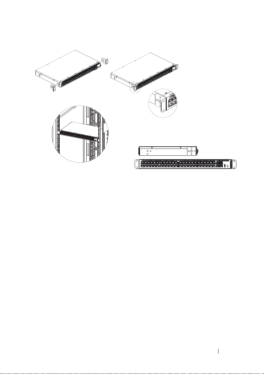
Figure 1-1. Bracket Installation for Rack Mounting
2
Insert the supplied screws into the rack mounting holes and tighten with
a screwdriver.
3
Repeat the process for the rack-mounting bracket on the other side of
the switch.
4
Insert the switch into the rack, making sure the rack-mounting holes on
the switch line up to the mounting holes on the rack.
5
Secure the switch to the rack with the rack screws (not provided).
Fasten the lower pair of screws before the upper pair of screws.
Make sure that the ventilation holes are not obstructed.
Flat Surface Installation
The switch can be installed on a flat surface if it is not installed on a rack.
The surface must be able to support the weight of the switch and the
switch cables.
Attach the self-adhesive rubber pads (provided with the switch) on each
1
marked location on the bottom of the chassis.
2
Set the switch on a flat surface, while leaving two inches (5.08 cm) on each
side and five inches (12.7 cm) at the back.
3
Make sure that the switch has proper ventilation.
Getting Started Guide 5
Page 8
Wall Installation
To mount the switch on a wall:
1
Make sure that the mounting location meets the following requirements:
• The surface of the wall must be capable of supporting the switch.
• Allow at least two inches (5.1 cm) space on the sides for proper
ventilation and five inches (12.7 cm) at the back for power
cable clearance.
• The location must be ventilated to prevent heat buildup.
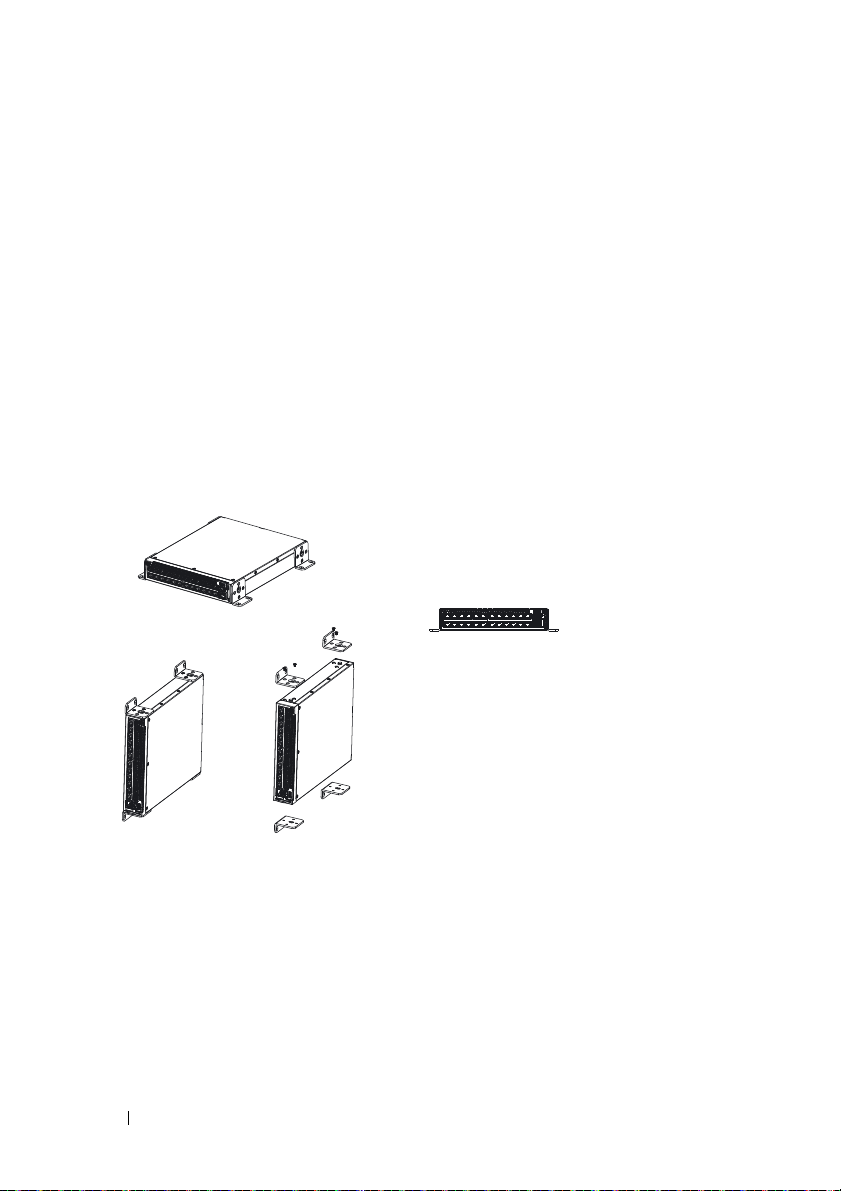
2
Place the supplied wall-mounting bracket on one side of the switch,
verifying that the mounting holes on the switch line up to the mounting
holes on the wall-mounting bracket.
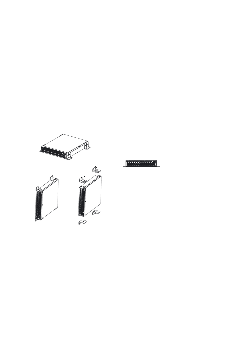
Figure 1-2. Bracket Installation for Wall Mounting
3
Insert the supplied screws into the wall-mounting bracket holes and
tighten with a screwdriver.
4
Repeat the process for the wall-mounting bracket on the other side of
the switch.
5
Place the switch on the wall in the location where the switch is being installed.
6
On the wall mark the locations where the screws to hold the switch must
be prepared.
6 Getting Started Guide
Page 9
7
On the marked locations, drill the holes and place all plugs (not provided)
in the holes.
8
Secure the switch to the wall with screws (not provided). Make sure that
the ventilation holes are not obstructed.
Starting and Configuring the Switch
Management Modes
The Dell Networking X1008/18/26 and equivalent PoE versions have a Mode
push button that toggles between Managed and Unmanaged Modes. The
MGMT LED is on when the switch is in Managed Mode and is off when in
Unmanaged Mode. To configure the switch while in Managed Mode, see the
following sections.
NOTE: Release notes and user documentation can be downloaded from
dell.com/support.
Connecting the Switch to the Network
CAUTION: Do not plug a phone jack connector into an RJ-45 port. This will
damage the Ethernet switch. Use only twisted-pair cables with RJ-45 connectors
that conform to FCC standards.
To connect the switch to the network:
• Attach one end of a twisted-pair cable to the switch's RJ-45 connector and
the other end of a twisted-pair cable to another switch or server.
As each connection is made, the link LED corresponding to each port on the
switch is illuminated (green or amber) indicating that the connection is valid.
Getting Started Guide 7
Page 10
Initial Configuration Through the Web
The administrator can perform switch configuration using the web
management GUI.
To configure the switch, perform the following:
1
Verify that the switch is in Managed Mode.
2
Connect the switch to a PC using Ethernet, and set a static IP address of
192.168.2.x
255.255.255.0
can receive its IP address from a DHCP server. If using DHCP for IP
assignment, look up the assigned IP address and use it for the next step.
3
Connect to the switch using the default switch IP address
your web browser. The login username is
4
After logging into the switch using the previous step, a getting started
wizard is available to guide the user through the initial switch
configuration. Applied changes are automatically saved to the startup
configuration.
(where x is between 2 and 254) and subnet mask of
on the PC. Note that the switch acts as a DHCP client and
192.168.2.1
admin
with password
admin
in
.
CLI Access
To access the switch using the Command Line Interface (CLI), it must be in
Managed Mode. The Command Line Interface can only be reached by using
telnet or a console connection. See the user guide for limited CLI options.
NOTE: The default switch setting is Unmanaged Mode. To set the switch to
Managed Mode, press the Mode button for at least seven seconds.
Connecting the Switch to a Terminal Server/PC
NOTE: The console port enables connecting to a terminal or desktop system
running terminal emulation software for monitoring or debugging the device using
the micro-USB port. (You can find the USB drivers at dell.com/support.)
To use the console port, the following is required (e.g., PuTTY, TeraTerm, etc.)
• VT100 compatible terminal or a desktop or portable system with a USB
port and running VT100 terminal emulation software.
8 Getting Started Guide
Page 11
To connect a terminal to the device console port, verify that the terminal
emulation software is set as follows:
1
Set the data rate to 9600 baud, data format to 8 data bits, 1 stop bit and
no parity.
2
Set flow control to none.
3
Select VT100 for Emulation mode.
Rebooting the Switch in Managed Mode
To reboot the switch, press the Reset button through the pinhole on the
switch for less than seven seconds.
Resetting the Switch in Managed Mode
To reset the switch to factory defaults, press the Reset button through the
pinhole on the switch for more than seven seconds.
CAUTION: When you reset the switch, any configuration information that has
been previously entered is lost.
Power Over Ethernet
The table below describes the PoE resources available for the various
switch models.
Table 1-2. Power Over Ethernet
PoE Switch Model Watts (dedicated POE
power only)
X1008 123 1-8
X1018p 246 1-16
Powered Ports
X1026p 369 1-24*
X1052p 369 1-24*
*These ports can be PoE or PoE+
Getting Started Guide 9
Page 12

10 Getting Started Guide
Page 13

Dell™ Networking™ X1000 和
X4000 系列交换机
使用入门指南
管制型号:X1008、X1008P、X1018、
X1026、X4012、X1018P、X1026P、
X1052、 X1052P
Page 14
注、小心和警告
注:“ 注 ” 表示可以帮助您更好地使用设备的重要信息。
小心:“ 小心 ” 表示可能会损坏硬件或导致数据丢失,并告诉您如何避免此
类问题。
警告:“ 警告 ” 表示可能会导致财产损失、人身伤害甚至死亡。
____________________
版权所有 © 2014 Dell Inc. 保留所有权利。本产品受美国和国际版权及知识产权法保护。
Dell™ 和 Dell 徽标是 Dell Inc. 在美国和 / 或其他司法管辖区的商标。文中涉及的所有其他商
标和名称可能是其各自公司的商标。
P/N RF9YW Rev. A00
Page 15

欢迎使用
本文档提供安装和启动以下 Dell 网络 X 系列交换机的基本信息:
X1008/X1008P、X1018/X1018P、X1026/X1026P、X1052/X1052P 和 X4012。
交换机出厂时为 Unmanaged Mode(未管理模式)以避免未授权访问交换
机。要在 Unmanaged Mode (未管理模式)下使用交换机,请按下 Mode
(模式)按钮至少 7 秒。在 Managed Mode(管理模式)下,MGMT LED
将会亮起。要切换回 Unmanaged Mode (未管理模式),请重复此过程。
这些 Dell 网络设备最适用于需要高性能网络连接和高级网络管理功能的
中小型企业。这些管理功能可最大程度减少管理投入,同时增强和提高网
络流量控制。
有关最新的文档和软件更新,请访问 dell.com/support。
印刷文档中包含安全、环境和法规信息 (SERI)。
包装内容
在拆开设备包装时,请确保随附以下物品:
•
订购的网络交换机
•AC
•
•
•
•
•
•
电源电缆 (以及仅适用于
控制台
micro-USB
自粘式橡胶垫 (适用于在特定系统上安装机台或机架)
安装套件
安全、环境和管制信息文档
垫子
本入门指南
串行电缆
X1008 和 X1008P
的电源模块)
使用入门指南 13
Page 16
X1000 和 X4000 系列交换机概述
表 1-1. X1000 和 X4000 系列交换机概述
营销型号名称 电源设备 管制型号 管制类型编号
X1008
X1008P
X1018
X1026
X4012
X1018P
X1026P
X1052
X1052P
外部, 24W
外部, 150W
内部, 40W
内部, 40W
内部, 100W
内部, 280W
内部, 450W
内部, 100W
内部, 525W
E08W E08W001
E09W E09W001
E10W E10W001
E10W E10W002
E10W E10W003
E11W E11W001
E11W E11W002
E12W E12W001
E12W E12W002
安装设备
机架安装
警告:请阅读 SERI 中的安全信息,以及连接或支持该交换机的其他交换机
的安全信息。
警告:在机架或机柜中安装交换机之前,请先断开交换机连接的所有电缆。
小心:将多台交换机安装到机架时,请按由下至上的顺序安装交换机。
按照以下说明在带托座的机架中安装交换机 (52 端口交换机有滑轨套件):
1
将随附的机架安装托座置于交换机的一侧,确保交换机上的安装孔与机
架安装托座上的安装孔对齐。
14 使用入门指南
Page 17
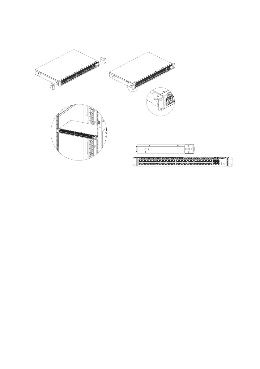
图 1-1. 机架安装托座的安装
2
将随附的螺钉插入机架安装孔,然后用螺丝刀拧紧。
3
对交换机另一侧的机架安装托座重复相同的操作过程。
4
将交换机插入机架,确保交换机上的机架安装孔与机架上的安装孔对齐。
5
使用机架螺钉 (未提供)将交换机固定到机架。先拧紧下方的螺钉对,
然后再拧紧上方的螺钉对。确保通风孔畅通无阻。
平坦表面安装
如果不在机架上安装,可将交换机安装在平坦表面上。该表面必须能够支
撑交换机和交换机电缆的重量。
1
将自粘式橡胶垫 (交换机随附)粘贴在机箱底部每个标记的位置。
2
将交换机放在平坦表面上,同时两侧保留
后侧保留
3
确保交换机有适当的通风。
5
英寸 (
12.7
厘米)的间隙。
2
英寸 (
5.08
厘米)的间隙,
使用入门指南 15
Page 18
墙壁式安装
要将交换机安装到墙上:
1
确保安装位置符合以下要求:
•
墙面必须可以支撑交换机的重量。
•
两侧保留至少
在后侧为电源电缆保留
•
该位置必须保持通风以防高温。
2
将随附的墙壁式安装托座置于交换机的一侧,验证交换机上的安装孔与
墙壁式安装托座上的安装孔对齐。
图 1-2. 墙壁式安装托座的安装
2
英寸 (
5.1
厘米)的间隙,以确保适当的通风,并
5
英寸 (
12.7
厘米)的间隙。
3
将随附的螺钉插入墙壁式安装托座孔,然后用螺丝刀拧紧。
4
对交换机另一侧的墙壁式安装托座重复相同的操作过程。
5
将交换机置于墙上要安装的位置。
6
在墙上标示出固定交换机所需的螺钉位置。
7
在标示的位置钻孔,然后在所有的孔中置入塞子 (未提供)。
8
使用螺钉 (未提供)将交换机固定到墙上。确保通风孔畅通无阻。
16 使用入门指南
Page 19
启动和配置交换机
管理模式
Dell 网络 X1008/18/26 和相当的 PoE 版本有一个 Mode (模式)按钮,可在
Managed Mode (管理模式)和 Unmanaged Mode (未管理模式)之间切
换。MGMT LED 会亮起,在处于 Managed Mode(管理模式)时熄灭。 要
对处于 Managed Mode(管理模式)的交换机进行配置,请参阅以下章节。
注:可以从 dell.com/support 下载发布说明和用户文档。
将交换机连接到网络
小心:切勿将电话连接器插入 RJ-45 端口。否则会损坏以太网交换机。请仅
在使用符合 FCC 标准的 RJ-45 连接器时使用双绞线电缆。
将交换机连接到网络:
•
将双绞线电缆的一端连接到交换机的
接到另一台交换机或服务器。
在每次建立连接时,交换机上对应每个端口的链接 LED 会亮起 (绿色或
琥珀色),表明连接正常。
通过网络进行初始配置
管理员可使用网络管理 GUI 执行交换机配置。
要配置交换机,请执行以下步骤:
1
验证交换机处于
2
使用以太网将交换机连接到
(其中
x 介于 2 和 254
交换机作为
DHCP 分配 IP
3
在网络浏览器中使用默认的交换机
登录用户名为
4
在使用上一步骤登录交换机后,开始向导会引导用户完成交换机的初始
配置。应用的更改会自动保存到启动配置。
Managed Mode
之间),以及子网掩码 255.255.255.0
DHCP
客户端,可从
地址,请查找分配的
admin
,密码为 admin
PC
RJ-45
(管理模式)。
,并在
PC
上设置静态
DHCP
服务器接收其
IP
地址,并将其用于下一个步骤。
IP 地址
。
端口,将双绞线的另一端连
IP 地址
192.168.2.1 来连接交换机。
192.168.2.x
。请注意,
IP
地址。若使用
使用入门指南 17
Page 20

CLI 访问
要使用命令行界面 (CLI) 访问交换机,交换机必须处于 Managed Mode
(管理模式)。命令行界面智能通过远程登录或控制台连接访问。有关受限
CLI 选项的信息,请参阅用户指南。
注:默认的交换机设置为 Unmanaged Mode (未管理模式)。要将交换机设
置为 Unmanaged Mode(未管理模式),请按下 Mode(模式)按钮至少 7 秒。
将交换机连接到终端服务器 /PC
注:控制台端口支持通过 micro-USB 端口连接终端或运行终端模式软件的台
式机系统,以监控或调试设备。(您可以在 dell.com/support 上查找 USB 驱
动程序。)
要使用控制台端口,需要以下各项 (例如, PuTTY、 Te r aTe rm 等。)
• VT100
将终端连接到设备控制台端口,验证终端模拟软件已进行如下设置:
1
2
3
重新启动处于 Managed Mode (管理模式)的交换机
要重新启动交换机,从交换机上的小孔按下 Reset(重置)按钮不超过 7 秒。
兼容的终端或具有
机或便携式系统。
将数据传输速率设置为
奇偶校验。
将流量控制设置为无。
选择
VT100 为 Emulation mode
USB
端口并运行
9600
波特,数据格式为
(模拟模式)。
VT100
终端模拟软件的台式
8
数据位,1 停止位,无
将交换机重置为 Managed Mode (管理模式)
要将交换机重置为出厂默认设置,从交换机上的小孔按下 Reset (重置)
按钮超过 7 秒。
小心:当您重置交换机时,先前输入的所有配置信息将会丢失。
18 使用入门指南
Page 21

以太网供电
下表说明了适用于各种交换机型号的 PoE 资源。
表 1-2. 以太网供电
PoE 交换机机型 瓦 (仅限专用 POE 电源) 供电端口
X1008 123 1-8
X1018p 246 1-16
X1026p 369 1-24*
X1052p 369 1-24*
* 这些端口可以为 PoE 或 PoE+
使用入门指南 19
Page 22

20 使用入门指南
Page 23

Dell™ Networking™ X1000 和
X4000 系列交換器
入門指南
安規型號:X1008、X1008P、X1018、
X1026、X4012、X1018P、X1026P、
X1052、X1052P
Page 24

註,警示,警告
註:「註」表示可以幫助您更有效地使用裝置的重要資訊。
警示:「警示」表示有可能會損壞硬體或導致資料遺失,並告訴您如何避免
發生此類問題。
警告:「警告」表示可能的財產損失、人身傷害或死亡。
____________________
Copyright © 2014 Dell Inc. 版權所有,翻印必究。本產品受到美國及國際著作權及智慧財產
權法律的保護。
Dell™ 和 Dell 徽標為 Dell Inc. 在美國及 / 或其他司法管轄區的商標。此處提及的所有其他標
記和名稱均為其各自公司的商標。
P/N RF9YW Rev. A00
Page 25

歡迎使用
本文件提供安裝和啟動以下 Dell 網路 X 系列交換器的基本資訊:
X1008/X1008P、X1018/X1018P、X1026/X1026P、X1052/X1052P 和 X4012。
交換器出廠時為 Unmanaged Mode ( 未管理模式 ),以避免未授權存取交換
器。如要在 Managed Mode ( 管理模式 ) 中使用交換器,請按下 Mode ( 模
式 ) 按鈕至少 7 秒。在 Managed Mode ( 管理模式 ) 中,MGMT LED 將會
亮起。如要切換回 Unmanaged Mode ( 未管理模式 ),請重複此程序。
這些 Dell 網路裝置最適用於需要高效能網路連接能力及高階網路管理功
能的中小型企業。這些管理功能可將投入的管理心力降至最低,同時增強
並改善網路傳輸控制。
如需最新的說明文件和軟體更新,請造訪 dell.com/support。
印刷版說明文件包含安全環境與法規資訊 (SERI)。
包裝內容
在拆卸包裝取出裝置時,請確定隨附以下品項:
•
訂購的網路交換器
•AC
•
•
•
•
•
•
電源線 (行動電源僅適用於
控制台
micro-USB
自黏式橡膠墊 (用於在特定系統上安裝機台或機架
安裝套件
安全、環保與法規資訊文件
墊子
本入門指南
序列纜線
X1008 和 X1008P)
)
入門指南 23
Page 26

X1000 和 X4000 系列交換器摘要
表 1-1. X1000 和 X4000 系列交換器摘要
行銷機型名稱 電源供應器 安規型號 安規類型編號
X1008
X1008P
X1018
X1026
X4012
X1018P
X1026P
X1052
X1052P
外部,24W
外部,150W
內部,40W
內部,40W
內部,100W
內部,280W
內部,450W
內部,100W
內部,525W
E08W E08W001
E09W E09W001
E10W E10W001
E10W E10W002
E10W E10W003
E11W E11W001
E11W E11W002
E12W E12W001
E12W E12W002
安裝裝置
機架安裝
警告:請閱讀 SERI 中的安全資訊,以及其他連接或支援本交換器的交換器
之安全資訊。
警告:將交換器安裝在機架或機櫃中之前,請先從交換器中斷連接所有纜線。
警示:將多部交換器安裝至機架時,請依由下而上的順序安裝交換器。
依照以下說明,將交換器安裝在含托架的機架 (52 埠交換器隨附一個現成
可用的滑軌套件 ):
1
將隨附的機架固定托架置於交換器一側,請確定交換器上的固定孔與機
架固定托架上的固定孔對齊。
24 入門指南
Page 27

圖 1-1. 機架固定托架安裝
2
將隨附的螺絲插入機架固定孔,然後使用螺絲起子鎖緊。
3
對交換器另一側的機架固定托架重複相同的程序。
4
將交換器插入機架,確定交換器上的機架固定孔與機架上的固定孔對齊。
5
使用機架螺絲 (未隨附) 將交換器固定至機架。請先鎖緊下方的螺絲組,
再鎖緊上方的螺絲組。確定通風孔未阻塞。
平坦表面安裝
如果不安裝在機架上的話,可將本交換器安裝在平坦表面。此表面必須可
支撐交換器和交換器纜線的重量。
1
將自黏式橡膠墊 (隨附於交換器) 貼在底架底部上每個標記的位置。
2
將交換器置於平坦表面,且兩側保留
的間隙。
3
確定交換器維持適當的通風。
2 吋 (5.08 公分)
,後側保留
5 吋 (12.7 公分)
入門指南 25
Page 28

壁式安裝
如要將交換器安裝在牆上:
1
確定安裝位置符合以下要求:
•
牆面必須可支撐交換器的重量。
•
請保留兩側至少
後側為電源線保留
•
此位置必須維持通風,以避免高溫。
2
將隨附的壁式固定托架置於交換器一側,請確定交換器上的固定孔與壁
式固定托架上的固定孔對齊。
圖 1-2. 壁式固定托架安裝
2 吋 (5.1
5吋 (12.7
公分) 的間隙,以維持適當的通風,並在
公分) 的間隙。
3
將隨附的螺絲插入壁式固定托架孔,然後使用螺絲起子鎖緊。
4
對交換器另一側的壁式固定托架重複相同的程序。
5
將交換器置於牆上要安裝交換器的位置。
6
在牆上標示固定交換器所需的螺絲孔位置。
7
在標示位置鑽孔,然後對所有孔都裝上塞子 (未隨附)。
8
使用螺絲 (未隨附) 將交換器固定至牆上。確定通風孔未阻塞。
26 入門指南
Page 29

啟動並設定交換器
管理模式
Dell 網路 X1008/18/26 和相當的 PoE 版本具有一個 Mode ( 模式 ) 按 鈕,可
在 Managed Mode ( 管理模式 ) 和 Unmanaged Mode ( 未管理模式 ) 之間切
換。當交換器處於 Managed Mode ( 管理模式 ) 時,MGMT LED 會亮起,
當處於 Unmanaged Mode ( 未管理模式) 時會熄滅。當交換器處於 Managed
Mode ( 管理模式 ) 時,如要設定交換器,請參閱以下各節。
註:您可從 dell.com/support 下載版本資訊和使用者說明文件。
將交換器連接至網路
警示:請勿將電話連接器插入 RJ-45 連接埠。這會使乙太網路交換器受損。
請僅使用具有符合 FCC 標準的 RJ-45 連接器的雙絞線。
將交換器連接至網路:
•
將雙絞線的一端連接至交換器的
至另一部交換器或伺服器。
在每次建立連線時,交換器上對應該連接埠的連結 LED 就會亮起 ( 綠色或
琥珀色 ),指出連線正常。
透過網頁進行初始組態設定
RJ-45
連接器,將雙絞線的另一端連接
管理員可使用網頁管理 GUI 來進行交換器設定。
如要設定交換器,請執行以下步驟:
1
確定交換器目前處於
2
使用乙太網路將交換器連接至
192.168.2.x (其中
請注意,交換器是當成
址。如果
步驟。
3
在您的網頁瀏覽器中使用預設的交換器
器。登入使用者名稱為
4
在使用上個步驟登入交換器後,開始使用精靈將會引導使用者完成初始
交換器組態設定。套用的變更將會自動儲存至啟動組態。
IP
指派使用
Managed Mode (
x 在 2 和 254
DHCP
DHCP
,請查詢指派的
admin
管理模式)。
PC
,並在
PC
上設定靜態
之間),以及子網路遮罩 255.255.255.0
用戶端,可從
,密碼為 admin
DHCP
IP
IP 位址
伺服器接收其
位址,並將它用於下個
192.168.2.1 來連接交換
。
入門指南 27
IP
位址
IP
。
位
Page 30

CLI 存取
如要使用指令行介面 (CLI) 存取交換器,交換器必須處於 Managed Mode
( 管理模式 )。指令行介面只能藉由 telnet 或控制台連線存取。有關有限的
CLI 選項,請參閱使用者指南。
註 : 預設的交換器設定為 Unmanaged Mode ( 未管理模式 )。如要將交換器設
為 Managed Mode ( 管理模式 ),請按下 Mode ( 模式 ) 按鈕至少 7 秒。
將交換器連接至終端伺服器 /PC
註 : 控制台連接埠可透過使用 micro-USB 連接埠來連接終端機或執行終端機
模擬軟體的桌上型電腦系統,以監控裝置或進行除錯。( 您可以在
dell.com/support 找到 USB 驅動程式。)
如要使用控制台連接埠,需要以下各項 ( 例如 PuTTY、Te ra Ter m 等。)
• VT100
將終端機連接至裝置控制台連接埠,確認終端機模擬軟體已進行以下設定:
1
2
3
將交換器重新啟動為 Managed Mode ( 管理模式 )
如要重新啟動交換器,請從交換器上的小孔按下 Reset ( 重設 ) 按鈕不超過
7 秒。
相容的終端機或具有
的桌上型電腦或可攜式系統。
將資料傳輸速率設為
無同位。
將流量控制設為無。
選擇
VT100 為 Emulation mode (
9600
USB
,資料格式設為
連接埠並執行
8
資料位元,1 停止位元,且
模擬模式)。
VT100
終端機模擬軟體
將交換器重設為 Managed Mode ( 管理模式 )
如要將交換器重設為出廠預設值,請從交換器上的小孔按下 Reset ( 重設 )
按鈕超過 7 秒。
警示:當您重設交換器時,之前輸入的組態資訊將會遺失。
28 入門指南
Page 31

使用乙太網路供電
下表說明適用於不同交換器機型的 PoE 資源。
表 1-2. 使用乙太網路供電
PoE 交換器機型 瓦特 (僅專用的 POE 功率) 供電連接埠
X1008 123 1-8
X1018p 246 1-16
X1026p 369 1-24*
X1052p 369 1-24*
* 這些連接埠可以為 PoE 或 PoE+
入門指南 29
Page 32

30 入門指南
Page 33

Sakelar Dell™ Networking™
Seri X1000 dan X4000
Panduan Pengaktifan
Model Regulatori: X1008, X1008P, X1018,
X1026, X4012, X1018P, X1026P, X1052,
X1052P
Page 34

Catatan, Perhatian, dan Peringatan
CATATAN : CATATAN menunjukkan informasi penting yang membantu Anda
memaksimalkan penggunaan perangkat.
PERHATIAN: PERHATIAN menunjukkan kerusakan potensial pada perangkat
keras atau kehilangan data yang mungkin terjadi dan memberitahukan Anda cara
menghindari masalah tersebut.
PERINGATAN: PERINGATAN menunjukkan potensi terjadinya kerusakan
properti, cedera pada seseorang, atau kematian.
____________________
Copyright © 2014 Dell Inc. Hak cipta dilindungi undang-undang. Produk ini dilindungi oleh
undang-undang hak kekayaan intelektual dan undang-undang hak cipta di AS dan internasional.
Dell™ dan logo Dell adalah merek dagang dari Dell Inc. di Amerika Serikat dan/atau yurisdiksi
lainnya. Semua merek dan nama lainnya yang disebutkan di sini bisa jadi merupakan mereka dagang
dari perusahaan yang bersangkutan.
No. Komp. RF9YW Rev. A00
Page 35

Selamat Datang
Dokumen ini menyediakan informasi dasar untuk memasang dan mulai
menjalankan sakelar Dell Networking seri-X berikut ini: X1008/X1008P,
X1018/X1018P, X1026/X1026P, X1052/X1052P dan X4012.
Sakelar tersebut dikirimkan dari pabrik dalam Mode Unmanaged (Tidak
Dikelola) untuk menghindari akses tidak berwenang terhadap sakelar
tersebut. Untuk menggunakan sekelar dalam Mode Managed (Dikelola),
tekan tombol Mode selama minimal tujuh detik. LED MGMT akan menyala
saat dalam Mode Managed (Dikelola). Untuk beralih kembali ke Mode
Unmanaged (Tidak Dikelola), ulangi proses tersebut.
Perangkat Dell networking ini ideal untuk bisnis kecil hingga menengah yang
memerlukan konektivitas jaringan kinerja tinggi bersama dengan fitur
manajemen web lanjutan. Fitur manajemen dirancang untuk meminimalkan
upaya manajemen administratif, sambil meningkatkan dan memperbaiki
kontrol lalu lintas jaringan.
Untuk dokumentasi terbaru dan pembaruan perangkat lunak,
buka dell.com/support.
Informasi Keselamatan, Lingkungan, dan Regulatori (Safety Environmental
and Regulatory Information / SERI) disertakan di dalam dokumentasi tercetak.
Isi Kemasan
Saat membuka kemasan perangkat, pastikan bahwa item-item berikut
ini disertakan:
• Sakelar jaringan yang dipesan
• Kabel daya AC (dan wadah cadangan daya hanya untuk X1008 dan X1008P)
• Kabel serial micro-USB konsol
• Bantalan karet dengan perekat (untuk instalasi di meja atau rak pada
sistem terpilih)
• Kit instalasi
• Dokumen Informasi Keselamatan, Lingkungan, dan Regulatori (Safety
Environmental and Regulatory Information)
•Alas
• Panduan Cara Memulai Ini
Panduan Pengaktifan 33
Page 36

Ringkasan Sakelar Seri X1000 dan X4000
Tabel 1-1. Ringkasan Sakelar Seri X1000 dan X4000
Nama Model
Pemasaran
X1008 Eksternal, 24W E08W E08W001
X1008P Eksternal, 150W E09W E09W001
X1018 Internal, 40W E10W E10W001
X1026 Internal, 40W E10W E10W002
X4012 Internal, 100W E10W E10W003
X1018P Internal, 280W E11W E11W001
X1026P Internal, 450W E11W E11W002
X1052 Internal, 100W E12W E12W001
X1052P Internal, 525W E12W E12W002
Unit Catu Daya Nomor Model
Regulatori
Nomor Jenis
Regulatori
Memasang Perangkat
Instalasi di Rak
PERINGATAN: Baca informasi keselamatan di dalam SERI serta juga informasi
keselamatan untuk sakelar lain yang dihubungkan ke atau mendukung
sakelar tersebut.
PERINGATAN: Lepaskan sambungan semua kabel dari sakelar sebelum
memasangkan sakelar ke dalam rak atau kabinet.
PERHATIAN: Saat memasangkan beberapa sakelar ke dalam rak, pasangkan
sakelar dengan urutan dari bagian bawah ke atas.
Pasang sakelar di dalam rak dengan bracket sebagai berikut (52 sakelar port
memiliki kit rel yang sudah siap pakai):
1
Letakkan bracket pemasangan rak yang dipasok pada salah satu sisi sakelar,
untuk memastikan bahwa lubang pemasangan pada sakelar sejajar dengan
lubang pemasangan pada bracket pemasangan rak.
34 Panduan Pengaktifan
Page 37

Gambar 1-1. Instalasi Bracket untuk Pemasangan Rak
2
Pasang baut yang telah disediakan ke lubang pemasangan rak dan
kencangkan dengan obeng.
3
Ulangi proses untuk bracket pemasangan rak di sisi lain sakelar tersebut.
4
Masukkan sakelar ke dalam rak, pastikan lubang pemasangan rak pada
sakelar sejajar dengan lubang pemasangan yang ada pada rak tersebut.
5
Amankan sakelar ke rak dengan menggunakan sekrup rak (tidak disediakan).
Kencangkan pasangan sekrup bagian bawah sebelum mengencangkan
pasangan sekrup bagian atas. Pastikan bahwa lubang ventilasi tidak terhalangi.
Instalasi di Permukaan Datar
Sakelar dapat dipasang pada permukaan datar jika tidak dipasang pada rak.
Permukaan harus dapat mendukung berat sakelar dan kabel sakelar.
1
Pasangkan bantalan karet berperekat (disediakan dengan sakelar) pada
setiap lokasi bertanda di bagian bawah chasis.
2
Atur sakelar pada permukaan datar, sambil menyisakan dua inci (5,08 cm)
pada setiap sisi dan lima inci (12,7 cm) di bagian belakang.
3
Pastikan sakelar tersebut memiliki ventilasi yang benar.
Panduan Pengaktifan 35
Page 38

Instalasi di Dinding
Untuk memasang sakelar pada dinding:
1
Pastikan lokasi pemasangan memenuhi persyaratan berikut:
• Permukaan dinding harus mampu menopang sakelar.
• Berikan ruang minimal dua inci (5,1 cm) pada setiap sisi untuk
ventilasi yang benar dan lima inci (12,7 cm) di bagian belakang ruang
keluar kabel daya.
• Lokasi harus memiliki sistem ventilasi untuk mencegah
pembentukan panas.
2
Letakkan bracket pemasangan-di-dinding yang dipasok pada salah satu sisi
sakelar, untuk memastikan bahwa lubang pemasangan pada sakelar sejajar
dengan lubang pemasangan pada bracket pemasangan-di-dinding.
Gambar 1-2. Instalasi Bracket untuk Pemasangan di Dinding
3
Pasang sekrup yang telah disediakan ke lubang pemasangan-di-dinding dan
kencangkan dengan obeng.
4
Ulangi proses untuk bracket pemasangan-di-dinding di sisi lain
sakelar tersebut.
5
Letakkan sakelar di dinding pada lokasi tempat sakelar tersebut dipasang.
6
Di dinding, tanda lokasi tempat sekrup akan menahan sakelar tersebut
harus disiapkan.
36 Panduan Pengaktifan
Page 39

7
Pada lokasi yang telah diberi tanda, buat lubang dan pasang semua pasak
(tidak disediakan) di lubang tersebut.
8
Amankan sakelar ke dinding dengan menggunakan sekrup (tidak disediakan).
Pastikan bahwa lubang ventilasi tidak terhalangi.
Memulai dan Mengonfigurasi Sakelar
Mode Manajemen
Dell Networking X1008/18/26 dan versi PoE yang ekuivalen memiliki tombol
tekan Mode yang mengalihkan antara Mode Managed (Dikelola) dan
Unmanaged (Tidak Dikelola). LED MGMT menyala saat sakelar berada
dalam Mode Managed (Dikelola) dan mati saat dalam Mode Unmanaged
(Tidak Dikelola). Untuk mengonfigurasi sakelar saat dalam Mode Managed
(Dikelola), lihat bagian berikut.
CATATAN : Catatan perilisan dan dokumentasi pengguna dapat diunduh dari
dell.com/support.
Menyambungkan Sakelar ke Jaringan
PERHATIAN: Jangan colokkan konektor jack telepon ke dalam port RJ-45. Hal ini
akan merusak sakelar Ethernet. Gunakan hanya kabel pasangan berpilin (twistedpair) dengan konektor RJ-45 yang sesuai dengan standar FCC.
Untuk menyambungkan sakelar ke jaringan:
• Pasangkan salah satu ujung kabel pasangan berpilin (twisted-pair) ke
konektor RJ-45 pada sakelar dan ujung lain dari kabel twisted-pair tesebut
ke sakelar lainnya atau server.
Setelah setiap koneksi dibuat, LED tautan yang sesuai dengan setiap port
pada sakelar tersebut akan menyala (hijau atau kuning) menunjukkan bahwa
koneksi tersebut valid.
Panduan Pengaktifan 37
Page 40

Konfigurasi Awal Melalui Web
Administrator dapat melakukan konfigurasi sakelar menggunakan GUI
manajemen web.
Untuk mengonfigurasi sakelar, lakukan hal sebagai berikut:
1
Verifikasikan bahwa sakelar tersebut ada dalam Mode Managed (Dikelola).
2
Sambungkan sakelar tersebut ke PC menggunakan Ethernet, dan atur
alamat IP statis
255.255.255.0
klien DHCP dan dapat menerima alamat IP-nya dari server DHCP. Jika
menggunakan DHCP untuk penugasan IP, carilah alamat IP yang
ditugaskan tersebut dan gunakan untuk langkah berikutnya.
3
Sambungkan sakelar tersebut menggunakan alamat IP sakelar default
192.168.2.1
admin
dengan sandi
4
Setelah masuk ke sakelar menggunakan langkah sebelumnya, wizard cara
memulai akan tersedia untuk memandu pengguna melalui konfigurasi
sakelar awal. Perubahan yang diterapkan akan otomatis disimpan ke
konfigurasi saat memulai.
192.168.2.x
pada PC. Catat bahwa sakelar tersebut bertindak sebagai
di dalam browser web Anda. Nama pengguna login adalah
(di mana x antara 2 dan 254) dan subnet mask
admin
.
Akses CLI
Untuk mengakses sakelar yang menggunakan Antarmuka Saluran Perintah
(Command Line Interface / CLI), sakelar harus ada dalam Mode Managed
(Dikelola). Command Line Interface hanya dapat dijangkau dengan
menggunakan telnet atau koneksi konsol. Lihat panduan pengguna untuk
opsi CLI terbatas.
CATATAN : Pengaturan sakelar default adalah Mode Unmanaged (Tidak Dikelola).
Untuk mengatur sakelar ke Mode Managed (Dikelola), tekan tombol Mode selama
minimal tujuh detik.
38 Panduan Pengaktifan
Page 41

Menyambungkan Sakelar ke Server Terminal/PC
CATATAN : Port konsol memungkinkan untuk menyambungkan ke terminal atau
sistem desktop yang menjalankan perangkat lunak emulasi terminal untuk
memantau atau debugging perangkat menggunakan port micro-USB. (Anda dapat
menemukan driver USB di dell.com/support.)
Untuk menggunakan port konsol, diperlukan hal berikut ini (cth., PuTTY,
Ter a Term , dl l.)
• Terminal yang kompatibel VT100 atau desktop atau sistem portabel dengan
port USB dan menjalankan perangkat lunak emulasi terminal VT100.
Untuk menyambungkan terminal ke port konsol perangkat, verifikasikan
bahwa perangkat lunak emulasi terminal diatur sebagai berikut:
1
Atur laju data ke 9600 baud, format data ke 8 data bit, 1 stop bit dan
tanpa parity.
2
Atur kontrol aliran ke tidak ada.
3
Pilih VT100 untuk mode Emulasi.
Melakukan booting ulang Sakelar dalam Mode Managed (Dikelola)
Untuk melakukan booting ulang sakelar, tekan tombol Reset melalui lubang
pin pada sakelar tersebut selama kurang dari tujuh detik.
Melakukan penyetelan ulang Sakelar dalam Mode Managed (Dikelola)
Untuk melakukan penyetelan ulang sakelar ke setelan default pabrik, tekan
tombol Reset melalui lubang pin pada sakelar tersebut selama kurang dari
tujuh detik.
PERHATIAN: Saat Anda menyetel ulang sakelar, setiap informasi konfigurasi
yang sebelumnya telah dimasukkan akan hilang.
Panduan Pengaktifan 39
Page 42

Power Over Ethernet (Daya Melalui Ethernet)
Tabel di bawah ini menggambarkan sumber daya PoE yang tersedia untuk
berbagai model sakelar.
Tabel 1-2. Power Over Ethernet (Daya Melalui Ethernet)
Model Sakelar PoE Watt (khusus untuk daya
POE saja)
X1008 123 1-8
X1018p 246 1-16
X1026p 369 1-24*
X1052p 369 1-24*
*Port ini bisa berupa PoE atau PoE+
Port yang Diberi Daya
40 Panduan Pengaktifan
Page 43

Dell™ Networking™
X1000 および X4000
シリーズスイッチ
はじめに
認可モデル:X1008、X1008P、X1018、
X1026、X4012、X1018P、X1026P、
X1052、X1052P
Page 44

メモ、注意、警告
メモ:デバイスを使いやすくするための重要な情報を説明しています。
注意:ハードウェアの損傷やデータの損失の可能性を示し、その危険を回
避するための方法を説明しています。
警告:物的損害、けが、または死亡の原因となる可能性があることを示し
ています。
____________________
著作権 © 2014 Dell Inc. 無断転載を禁じます。この製品は、米国および国際著作権法、な
らびに米国および国際知的財産法で保護されています。
Dell™、お よ び Dell のロゴは、米国および / またはその他管轄区域における Dell Inc. の商
標です。本書で使用されているその他すべての商標および名称は、各社の商標である場合
があります。
P/N RF9YW Rev.A00
Page 45

ようこそ
本マニュアルには、次の Dell Networking X シリーズスイッチの取り付
けおよび起動の基本情報を記載しています。X1008/X1008P、
X1018/X1018P、 X1026/X1026P、 X1052/X1052P、X4012
スイッチへの不正アクセスを防ぐため、スイッチはアンマネージドモー
ドで出荷されます。スイッチをマネージドモードで使用するには、モー
ドボタンを 7 秒以上押します。マネージドモードになると、MGMT LED
が点灯します。スイッチをアンマネージドモードに戻すには、この手順を
繰り返します。
このような Dell ネットワーキングデバイスは、高度な Web 管理機能と
共に高性能なネットワーク接続が必要な中小企業に最適です。管理機能
は、ネットワークトラフィック制御を強化し向上させる一方で、経営管
理努力を最小限に抑えるように設計されています。
最新のマニュアルおよびソフトウェアについては、dell.com/support を
ご覧ください。
安全環境および規制情報(SERI)は印刷したマニュアルに含まれます。
パッケージ内容
デバイスを開梱する際に、次のアイテムが含まれていることを確認して
ください。
•
注文したネットワークスイッチ
•
AC
電源ケーブル(
含まれます)
•
コンソール
•
粘着ゴムパッド(選択システムに取り付けるデスクまたは棚用)
•
取り付けキット
•
安全環境、および規制情報マニュアル
•
プレースマット
•
スタートガイド
micro-USB
X1008
および
シリアルケーブル
X1008P
の場合のみ電源ブリックも
はじめに 43
Page 46

X1000 および X4000 シリーズスイッチ概要
表 1-1. X1000 および X4000 シリーズスイッチ概要
製造モデル名 電源ユニット 認可モデル番号 認可タイプ番号
X1008
X1008P
X1018
X1026
X4012
X1018P
X1026P
X1052
X1052P
外部、24W
外部、150W
内部、40W
内部、40W
内部、100W
内部、280W
内部、450W
内部、100W
内部、525W
E08W E08W001
E09W E09W001
E10W E10W001
E10W E10W002
E10W E10W003
E11W E11W001
E11W E11W002
E12W E12W001
E12W E12W002
デバイスを取り付ける
ラックへの取り付け
警告:SERI の安全情報と、スイッチに接続する、またはスイッチをサポー
トする他のスイッチの安全情報をお読みください。
警告:ラックまたはキャビネットにスイッチを取り付ける前に、スイッチ
からすべてのケーブルを外します。
注意:複数のスイッチをラックに取り付ける場合は、下の方から取り付け
ます。
次のようにスイッチをブラケットと一緒にラックに取り付けます(52 の
ポートスイッチにはレディレールキットがあります)。
1
同梱のラック取り付けブラケットを、スイッチの取り付け穴がラック
取り付けブラケットの取り付け穴に重なるように、スイッチの片側に
置きます。
44 はじめに
Page 47

図 1-1. ラック取り付け用ブラケットの取り付け
2
同梱のネジをラック取り付け穴に挿入し、ドライバーで締めます。
3
スイッチのもう一端のラック取り付けブラケットも同様の手順を繰
り返します。
4
スイッチのラック取り付け穴がラックの取り付け穴に重なるように、
スイッチをラックに差し込みます。
5
ラックネジ(同梱されていません)でスイッチをラックに固定します。
上の
2
つのネジの前に、下の
いようにしてください。
2
つのネジを締めます。通気口を塞がな
平らな面への取り付け
スイッチをラックに取り付けない場合は、平らな面に取り付けることが
できます。その面はスイッチとスイッチケーブルの重さに耐えらる場所
にする必要があります。
1
シャーシの底面のマークを付けた各場所に粘着ゴムパッド(スイッチ
に同梱)を貼り付けます。
2
スイッチを、両側に
の幅を残して、平らな面にセットします。
3
スイッチが適切に通気されるようにします。
5.08 cm(2
インチ)と背面に
12.7 cm(5
はじめに 45
インチ)
Page 48

壁への取り付け
スイッチを壁に取り付けるには:
1
取り付け場所が次の要件を満たしていることを確認してください。
•
壁の表面がスイッチを支えられる。
•
適切な通気用に両側に少なくとも
ケーブル用に背面に
•
温度の上昇を防ぐため通気性のある場所である。
2
同梱の壁取り付けブラケットを、スイッチの取り付け穴が壁取り付け
ブラケットの取り付け穴に重なるように、スイッチの片側に置きます。
図 1-2. 壁取り付け用ブラケットの取り付け
12.7 cm(5
5.1 cm(2
インチ)のスペースができる。
インチ)と、電源
3
同梱のネジを壁取り付けブラケットの穴に挿入し、ドライバーで締め
ます。
4
スイッチのもう一端の壁取り付けブラケットも同様の手順を繰り返
します。
5
スイッチを取り付ける予定の壁にスイッチを置きます。
6
スイッチを固定するネジを取り付ける場所にマークを付けます。
7
マークを付けた場所に、穴をあけてすべてのプラグ(同梱されていま
せん)を穴に差し込みます。
8
ネジ(同梱されていません)でスイッチを壁に固定します。通気口を
塞がないようにしてください。
46 はじめに
Page 49

スイッチの起動および設定
モードの管理
Dell Networking X1008/18/26 および 同等の PoE バージョンには、マ
ネージドモードとアンマネージドモードを切り替えるモードプッシュボ
タンがあります。スイッチがマネージドモードの場合は MGMT LED が
点灯し、アンマネージドモードの場合は消灯します。マネージドモード
中にスイッチを設定するには、次の項を参照してください。
メモ:リリースノートおよびユーザーマニュアルは dell.com/support か
らダウンロードできます。
スイッチをネットワークに接続
注意:モジュラージャックコネクタを RJ 45 ポートに差し込まないでくだ
さい。これはイーサネットスイッチを損傷する原因となります。FCC 基準
を満たす RJ 45 コネクタには、ツイストペアケーブルのみ使用します。
スイッチをネットワークに接続するには:
•
ツイストペアケーブルの一端をスイッチの
方の端を別のスイッチかサーバーに取り付けます。
それぞれ接続したら、スイッチの各ポートに対応するリンク LED が点灯
(緑またはオレンジ)し、接続が有効であることを示します。
RJ 45
コネクタに、もう一
Web による初期設定
管理者は、Web 管理 GUI を使用してスイッチの設定を行なうことがで
きます。
スイッチを設定するには、次の手順を行います。
1
スイッチがマネージドモードであることを確認します。
2
イーサネットを使用して
(x は
2 と 254
ネットマスクを設定します。スイッチが
役割を果たし、
割り当てに
スを調べて、次の手順で使用します。
の間)の静的
DHCP
DHCP
PC
にスイッチを接続し、
IP
アドレスと、
DHCP
サーバーから
を使用している場合は、割り当てられた
IP
アドレスを受け取れます。
PC で192.168.2.x
255.255.255.0
クライアントとしての
はじめに 47
IP
のサブ
IP
の
アドレ
Page 50

3
Web
ブラウザでデフォルトのスイッチ
用して、スイッチに接続します。
スワードも
4
前の手順でスイッチにログインしたら、開始ウィザードでユーザーは
スイッチの初期設定に進みます。適用された変更は起動設定に自動的
に保存されます。
admin
です。
IP
アドレス
ログインユーザー名は
192.168.2.1
admin
を使
でパ
CLI アクセス
コマンドラインインターフェース(CLI)を使用してスイッチにアクセス
するには、マネージドモードである必要があります。コマンドラインイ
ンターフェースは、テルネットまたはコンソール接続を使用してのみ利
用できます。制限つき CLP オプションについては、ユーザーズガイドを
参照してください。
メモ:スイッチのデフォルト設定はアンマネージドモードです。スイッチを
マネージドモードに設定するには、モードボタンを 7 秒以上押します。
スイッチをターミナルサーバー /PC に接続
メモ:コンソールポートは、micro-USB ポートを使用するデバイスをモニ
タリングまたはデバッグするための、ターミナルエミュレーションソフト
ウェアを実行するターミナルまたはデスクトップに接続できます。(USB ド
ライバは dell.com/support にあります。)
コンソールポートを使用するには、次が必要です(例、PuTTY、TeraTerm
など)。
•
VT100
ウェアを実行している
ブルシステム
ターミナルをデバイスコンソールポートに接続するには、ターミナルエ
ミュレーションソフトウェアが次のように設定されていることを確認し
ます。
1
データ転送速度を
トップビット、パリティなしに設定します。
2
フロー制御を「なし]に設定します。
3
エミュレーションモード用の
互換ターミナル、
USB
9600 baud
VT100
ターミナルエミュレーションソフト
ポートのあるデスクトップまたはポータ
に、データ形式を
VT100
を選択します。
8
データビット、1ス
48 はじめに
Page 51

マネージドモードでのスイッチの再起動
スイッチを再起動するには、スイッチのピンホールからリセットボタンを
7 秒を超えないように押します。
マネージドモードでのスイッチのリセット
スイッチを出荷時の設定にリセットするには、スイッチのピンホールか
らリセットボタンを 7 秒以上押します。
注意:スイッチをリセットすると、前に入力した設定情報がすべて消失し
ます。
パワーオーバーイーサネット(POE)
下記の表は様々なスイッチモデルで使用可能な PoE リソースを説明し
ています。
表 1-2. パワーオーバーイーサネット(POE)
PoE スイッチモデル ワット( POE 専用電源のみ)電源ポート
X1008 123 1-8
X1018p 246 1-16
X1026p 369 1-24*
X1052p 369 1-24*
* これらのポートは PoE または PoE+ の場合があります
はじめに 49
Page 52

50 はじめに
Page 53

Dell™ Networking™ X1000
및 X4000 시리즈 스위치
시작 안내서
규정 모델: X1008, X1008P, X1018,
X1026, X4012, X1018P, X1026P,
X1052, X1052P
Page 54

주, 주의 및 경고
주: "주"는 장치를 보다 효율적으로 사용할 수 있는 중요 정보를 제공합니다.
주의: "주의"는 하드웨어의 손상 또는 데이터 유실 위험을 설명하며, 이러한
문제를 방지할 수 있는 방법을 알려줍니다.
경고: "경고"는 재산 손실, 신체적 상해 또는 사망 위험이 있음을 알려줍니다.
____________________
Copyright © 2014 Dell Inc. 저작권 본사 소유. 이 제품은 미국 연방 및 국제 저작권 및 지적 재
산권에 의거 보호됩니다.
Dell™ 및 Dell 로고는 미국 및/또는 기타 법적 관할지에서 Dell Inc.의 상표입니다. 여기에 언
급된 다른 모든 마크와 이름은 해당 회사의 상표일 수 있습니다.
P/N RF9YW Rev. A00
Page 55

환영합니다
본 문서는 X1008/X1008P, X1018/X1018P, X1026/X1026P, X1052/X1052P,
X4012 등과 같은 Dell Networking X-시리즈 스위치의 설치와 실행 시작을
위한 기본 정보를 제공합니다.
이 스위치는 무단 접속을 피하기 위해 언매니지드 모드 상태로 공장에서
출하됩니다. 매니지드 모드로 스위치를 이용하려면 모드 버튼을 7초 이상
누르십시오. 매니지드 모드로 전환되면 MGMT LED에 조명이 들어옵니
다. 언매니지드 모드로 다시 돌아가려면 전환 과정을 똑같이 되풀이하십
시오.
이들 Dell 네트워킹 장치는 고성능
필요로 하는 중소 기업에게 이상적입니다. 이 관리 기능들은 관리 사무를
최소화하면서 네트워크 트래픽 제어를 향상 및 개선하기 위해 설계되었습
니다.
최신 문서와 소프트웨어 업데이트를 확인하시려면 dell.com/support를 방
문하십시오.
해당 웹사이트에 안전환경규제정보(SERI)가 인쇄물 형태로 게시되어 있
습니다.
패키지 내용물
이 네트워킹 장치의 포장을 풀 때 다음 품목이 모두 있는지 확인하십시오.
•
주문한 네트워크 스위치
•AC 전원
•
콘솔 마이크로
•
접착식 고무 패드(엄선된 시스템의 책상 또는 선반 설치 용도
•
설치 키트
•
안전, 환경 및 규제 정보 문서
•
플레이스매트
•
시작 안내서
케이블 (및
-USB 직렬
X1008 및 X1008P 전용 전원 브릭)
네트워크 연결과 고급 웹 관리 기능을
케이블
)
시작 안내서 53
Page 56

X1000 및 X4000 시리즈 스위치 요약
표 1-1. X1000 및 X4000 시리즈 스위치 요약
마케팅 모델명 전원 공급 장치 규정 모델 번호 규정 유형 번호
X1008
X1008P
X1018
X1026
X4012
X1018P
X1026P
X1052
X1052P
외부, 24W
외부, 150W
내부, 40W
내부, 40W
내부, 100W
내부, 280W
내부, 450W
내부, 100W
내부, 525W
E08W E08W001
E09W E09W001
E10W E10W001
E10W E10W002
E10W E10W003
E11W E11W001
E11W E11W002
E12W E12W001
E12W E12W002
장치 마운팅
랙 설치
경고: SERI에 수록된 안전 정보와 해당 스위치를 지원하거나 스위치에 연결
되는 다른 스위치의 안전 정보를 읽어 보십시오.
경고: 랙 또는 캐비닛에 스위치를 마운팅하기 전에 스위치에 꽂혀 있는 모든
케이블을 분리합니다.
주의: 여러 개의 스위치를 하나의 랙에 마운팅할 때 스위치를 아래에서부터
위로 마운팅합니다.
스위치를 브래킷이 부착된 랙에 설치할 때 다음 지시를 따릅니다(52 포트
스위치에는 준비된 레일 키트가 있습니다).
1
스위치와 함께 공급된 랙 마운팅 브래킷을 스위치 한쪽 면에 올려 놓고
스위치 라인의 마운팅 구멍이 랙 마운팅 브래킷의 마운팅 구멍에 정렬
되게
합니다
.
,
54 시작 안내서
Page 57

그림 1-1. 랙 마운팅을 위한 브래킷 설치
2
스위치와 함께 공급된 나사를 랙 마운팅 구멍 안에 넣고 드라이버로 조
입니다
.
3
똑같은 방법으로 스위치의 다른 쪽 면에 랙 마운팅 브래킷을 설치합니다
4
스위치를 랙 안에 넣고, 스위치 라인의 랙 마운팅 구멍이 랙의 마운팅 구
멍에
정렬되게 합니다
5랙
나사(별도 판매)를 이용해서 스위치를 랙에 고정시킵니다. 상단의
한
나사
멍이
쌍을 조이기 전에 먼저 하단의 나사 한 쌍을 조입니다. 환기 구
막히지 않게 주의하십시오
.
.
.
수평면 설치
스위치를 랙에 설치하지 않는다면 수평면에 설치할 수 있습니다. 스위치
와 스위치 케이블의 무게를 지탱할 수 있는 수평면이어야 합니다.
1
접착식 고무 패드(스위치와 함께 제공됨)를 섀시 하단에 표시된 각 위치
에
부착합니다
2양
옆으로
두어
,
스위치를 수평면에 올려 놓습니다
3
스위치 환기가 잘 되는지 확입합니다
.
5.08 cm(2인치)
간격을 두고 뒤쪽으로
.
.
12.7 cm(5인치)
시작 안내서 55
간격을
Page 58

벽면 설치
스위치를 벽면에 마운팅하려면.
1
마운팅 위치가 다음 요건을 준수해야 합니다
•
스위치를 지탱할 수 있는 벽면이어야 합니다
•
환기가 잘 되도록 양 옆으로
원
케이블을 설치할 공간을 확보하기 위해 뒤쪽으로
간격을 두어야 합니다
•
과열 방지를 위해 환기가 잘 되는 위치를 선택해야 합니다
2
스위치와 함께 공급된 벽면 마운팅 브래킷을 스위치 한쪽 면에 올려 놓
고
스위치 라인의 마운팅 구멍이 벽면 마운팅 브래킷의 마운팅 구멍에
정렬되게
그림 1-2. 벽면 마운팅을 위한 브래킷 설치
합니다
.
5.1 cm(2인치) 이상
.
.
.
간격을 두어야 하고 전
12.7 cm(5인치)
.
3
스위치와 함께 공급된 나사를 벽면 마운팅 구멍 안에 넣고 드라이버로
조입니다
4
똑같은 방법으로 스위치 다른 쪽 면에 벽면 마운팅 브래킷을 설치합니다
5
스위치를 설치할 벽면 위치에 스위치를 올려 놓습니다
6
스위치를 벽에 고정할 나사 위치를 벽에 표시해 둡니다
7
표시한 위치에 구멍을 뚫고 모든 플러그(별도 판매)를 구멍 안에 넣습니다
8
나사(별도 판매)를 이용해서 스위치를 벽면에 고정합니다. 환기 구멍이
막히지
56 시작 안내서
.
않게
주의하십시오
.
.
.
.
.
Page 59

스위치 작동 개시와 구성
관리 모드
Dell Networking X1008/18/26과 그와 동등한 가치를 지닌 PoE 버전 제품들
은 매니지드 모드와 언매지니드 모드 사이를 토글하는 모드 푸시 버튼이
있습니다. MGMT LED에 조명이 들어오면 스위치가 매니지드 모드에 있
는 것이고 조명이 들어오지 않으면 언매니지드 모드에 있는 것입니다. 매
니지드 모드 상태에서 스위치를 구성하려면, 다음 섹션을 참조하십시오.
주: 배포 자료와 사용 설명서를 dell.com/support에서 다운로드 받을 수 있습
니다.
스위치를 네트워크에 연결하기
주의: 폰 잭 커넥터를 RJ-45 포트에 플러그인하지 마십시오. 플러그인할 경
우 이더넷 스위치가 손상될 수 있습니다. FCC 표준에 부합되는 RJ-45 커넥
터가 연결된 트위스티드 페어 케이블만 사용하십시오.
스위치를 네트워크에 연결하려면
•
트위스티드 페어 케이블의 한쪽 끝을 스위치의
고
트위스티드 페어 케이블의 다른 쪽 끝을 다른 스위치 또는 서버에 부
착합니다
케이블 양끝이 연결되면 스위치의 각 포트에 해당되는 링크 LED에 조명
(녹색 또는 주황색)이 들어와 연결되었음을 나타냅니다.
.
RJ-45
커넥터에 부착하
웹을 통한 초기 구성
관리자는 웹 관리 GUI를 이용해서 스위치를 구성할 수 있습니다.
스위치를 구성하려면 다음 작업을 수행합니다.
1
스위치가 매니지드 모드에 있는지 확인합니다
2
이더넷을 이용해서 스위치를
(
여기서 x는
에 설정합니다. 스위치가
DHCP
당을
위해 DHCP를
계에서
2 ~ 254
서버로부터
그
주소를 이용해야 합니다
숫자입니다)와 서브넷 마스크 255.255.255.0을 PC
IP
주소를 받을 수 있다는 점에 유의하십시오
이용할 경우에, 배정된
PC에
DHCP
연결하고, 정적
클라이언트와 같은 역할을 하고
.
.
IP 주소
IP
주소를 찾아보고 다음 단
시작 안내서 57
192.168.2.x
. IP
할
Page 60

3웹
브라우저에 있는 기본 스위치
에
접속합니다. 로그인 사용자명은 admin이고
4앞
단계에서 스위치에 로그인한 후, 시작 마법사를 이용해서 초기 스위
치
구성
방법을 안내 받을 수 있습니다. 적용된 변경 사항이 시동 구성에
자동으로
저장됩니다
.
IP 주소
192.168.2.1을
비밀번호는 admin
이용해서 스위치
입니다
CLI Access
명령줄 인터페이스(CLI)를 이용해서 스위치에 접속하려면 매니지드 모드
에서 접속해야 합니다. 텔넷 또는 콘솔 연결을 통해서만 명령줄 인터페이
스에 접속할 수 있습니다. 한정된 CLI 옵션에 대해서는 사용 설명서를 참
조하십시오.
주: 기본 스위치 설정은 언매니지드 모드입니다. 매니지드 모드로 스위치를
설정하려면 모드 버튼을 7초 이상 누릅니다.
스위치를 터미널 서버/PC에 연결하기
주: 콘솔 포트는 마이크로-USB 포트를 이용해서 장치를 모니터하거나 디버
그하기 위해 터미널 에뮬레이션 소프트웨어를 실행하는 터미널 또는 데스
크탑 시스템에 대한 연결을 활성화합니다. (dell.com/support에서 USB 드라
이버를 찾을 수 있습니다.)
콘솔 포트를 이용하려면 다음 품목이 있어야 합니다(예
•USB
터미널을 장치 콘솔 포트에 연결하려면 터미널 에뮬레이션 소프트웨어가
다음과 같이 설정되어 있는지 확인합니다.
1
2
3
포트가 달려 있고
VT100 호환
는
데이터 속도를
정지 비트, 및 패리티 없음으로 설정합니다
1
흐름 제어를 없음으로 설정합니다
에뮬레이션 모드를 위한
터미널 또는 데스크탑이나 휴대용 시스템
9600 보(baud)로
VT100
VT100을
터미널 에뮬레이션 소프트웨어를 실행하
설정하고 데이터 포맷을
.
선택합니다
: PuTTY, TeraTerm 등).
.
8
데이터 비트
.
.
.
,
매니지드 모드에서 스위치를 재부팅하기
스위치를 재부팅하려면, 스위치의 핀홀을 통해 리셋 버튼을 7초 미만의 시
간 동안 누릅니다.
58 시작 안내서
Page 61

매니지드 모드에서 스위치를 리셋하기
스위치를 공장 출고 시 기본값으로 리셋하려면, 스위치의 핀홀을 통해 리
셋 버튼을 7초 이상 누릅니다.
주의: 스위치를 리셋하면, 앞서 입력한 구성 정보를 잃게 됩니다.
파워 오버 이더넷(PoE)
아래 표에는 다양한 스위치 모델에서 이용할 수 있는 PoE 리소스가 나열되
어 있습니다.
표 1-2. 파워 오버 이더넷(PoE)
PoE 스위치 모델 와트 (전용 POE 전원에만
해당됨)
X1008 123 1-8
X1018p 246 1-16
X1026p 369 1-24*
X1052p 369 1-24*
*포트는 PoE 또는 PoE+가 될 수 있습니다.
전원 포트
시작 안내서 59
Page 62

60 시작 안내서
 Loading...