

Page 1

Dell Networking C9010
REGULATORY DRAFT 11-4-14
Getting Started Guide
Regulatory Model: C9010
Page 2

Notes, Cautions, and Warnings
REGULATORY DRAFT 11-4-14
: A NOTE indicates important information that helps you make better use of your computer.
NOTE
CAUTION: A CAUTION indicates either potential damage to hardware or loss of data and tells you
how to avoid the problem.
WARNING: A WARNING indicates a potential for property damage, personal injury, or death.
Copyright © 2014 Dell Inc. All rights reserved. This product is protected by U.S. and international copyright and
intellectual property laws. Dell™ and the Dell logo are trademarks of Dell Inc. in the United States and/or other
jurisdictions. All other marks and names mentioned herein may be trademarks of their respective companies.
2014 - XX
Rev. A00
Page 3

About This Guide
REGULATORY DRAFT 11-4-14
This document provides basic information about how to install the C9010 switch with the base
configuration in a rack and perform the initial software configuration. For complete information about
C9010 installation and configuration, refer to these documents:
Table 1. C9010 Documentation
Information Documentation
Hardware installation and power-up instructions Dell Networking Installation Guide for the C9010
Switch
Software configuration Dell Networking Configuration Guide for the
C9000 Series
Command line interface Dell Networking Command Line Reference Guide
for the C9000 Series
Latest updates Dell Networking Release Notes for the C9010
Switch
1
About This Guide
3
Page 4

2
REGULATORY DRAFT 11-4-14
C9010 Hardware Description
This guide describes how to get started by installing the C9010 in a rack and connecting to a network.
The C9010 switch is part of Dell Networking's next-generation LAN solution, providing a scalable switch
that offers a path to higher density 10GE, 40GE, and 100GE capability. You can deploy the C9010 switch
as an access or aggregation/core switch for installations in which a modular switch is preferred to a stack.
You can also connect C1048P port extenders as access devices for larger port requirements.
The C9010 switch is a medium density platform that supports up to 240 10GE, or 60 40GE ports or a
combination of port speeds and media types, such as copper, fiber, and direct access cable (DAC). It has
an 8U chassis with up to 18” depth (19” with rack ears mounted). When fully loaded, it supports the
following components:
• Two full-width Route Processor modules (RPMs) with four 10GE uplinks per module
• Ten half-width Ethernet line cards, including:
– 6-Port 40GE QSFP+
– 24-Port 1/10GE SFP+
– 24-Port 1/10GE-Base-T RJ-45
The maximum port capability is up to 240 1GE ports or up to 240 10GE ports or up to 60 40GE ports.
• Three hot-swappable fan trays with side-to-side airflow (draws air through ventilation holes on the
right side of the chassis and expels air through ventilation holes on the left side)
• Four 2900 watt AC power supply units (PSUs)
The slot numbers of all installed components are shown in the following figure.
4
C9010 Hardware Description
Page 5
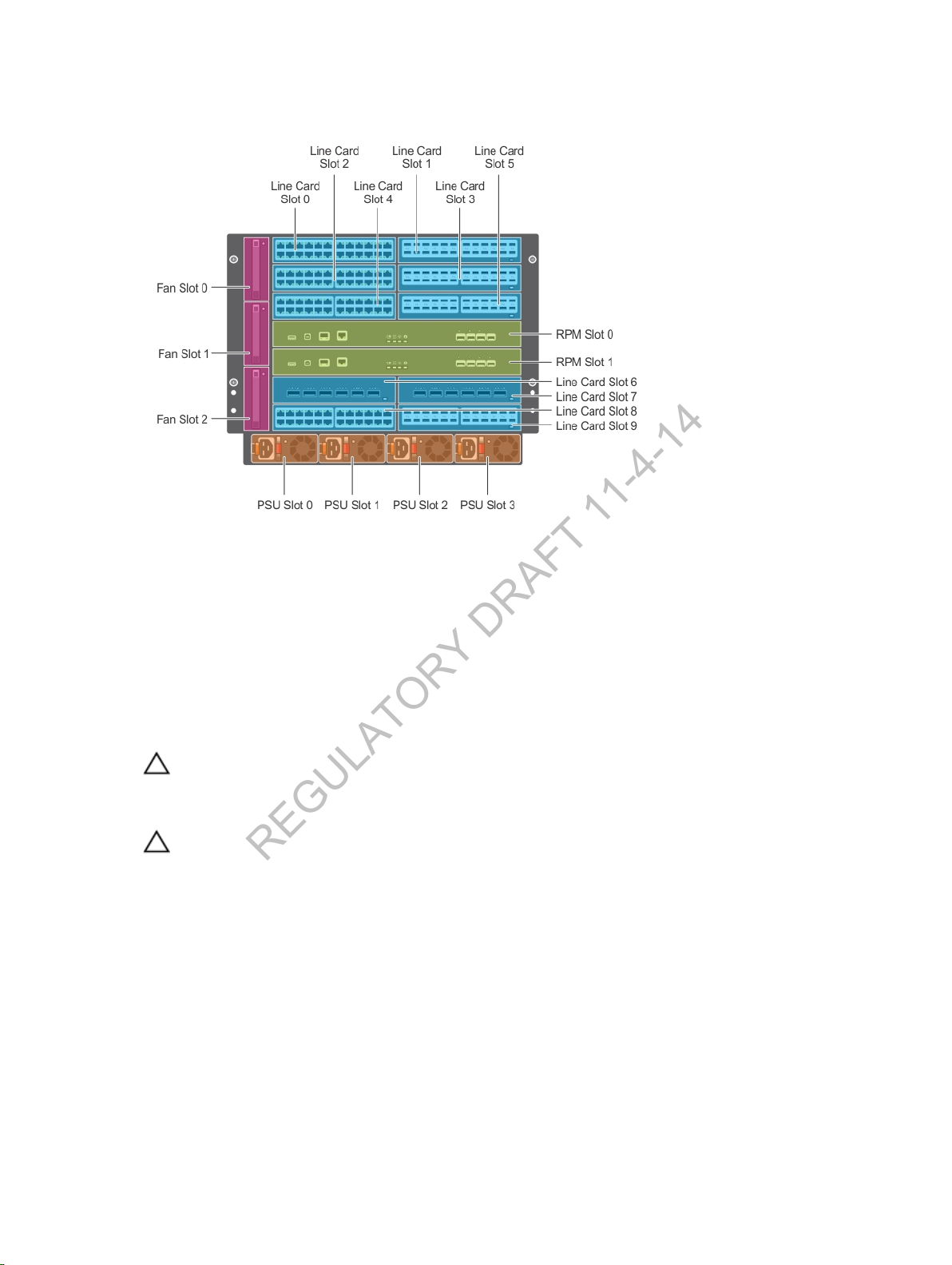
Figure 1. C9010 Chassis — Installed Components with Slot Numbers
REGULATORY DRAFT 11-4-14
Unpacking the Switch
The switch and its accessories are shipped in a single box. The power cords may be shipped in a separate
box. Before unpacking the switch, inspect the container and immediately report any evidence of damage.
Verify that you have received your ordered items. If any item is missing or damaged, contact your Dell
Networking representative or reseller for assistance.
CAUTION
and its components. Ground yourself by using an antistatic wrist strap or other device and
connect it to the ESD grounding jack on the chassis. As with all electrical devices of this type, take
all necessary safety precautions to prevent injury when installing this system.
CAUTION
pallet jack to lift or install the chassis. Lifting the system by its shelves will cause damage to the
chassis.
Unpack the C9010 by carefully removing the device from the container and place it on a secure and
clean surface.
The base C9010 configuration package is shipped with:
• C9010 chassis
• One full-width Route Processor module (RPM)
• Three fan trays
• One AC power supply
: Always wear an ESD-preventive wrist or heel ground strap when handling the switch
: The system is packaged in one or two separate containers. Use an equipment lift or
C9010 Hardware Description
5
Page 6

• One rack bar
REGULATORY DRAFT 11-4-14
• Two cable management brackets
• C9010 Getting Started Guide
• Safety and Regulatory Information
• Warranty and Support Information
• Software License Agreement
In addition, you can order the following items:
• A second RPM for redundancy
• Up to three additional PSUs; a second PSU is used for redundancy.
• Half-width line cards:
– 6-Port 40GE QSFP+
– 24-Port 10GE SFP+
– 24-Port 10GE BaseT
• SFP+ optics
• QSFP+ optics
• SFP+ direct attach copper (DAC) cables
• QSFP+ DAC cables
• Accessory kit, consisting of console cable, AC power cord and ESD wrist strap
• Dell ReadyRails
• Half- and full-width blanks
™ kit (#1 and #2 Phillips and flat-tipped screwdrivers required)
Before You Start: Site Preparation
Before installing the C9010 switch, make sure that your installation site meets these requirements:
• Clearance
space around and behind the switch for cabling, power connections, and ventilation. The AC power
cord can reach from the power outlet to the Utility-panel connector. Airflow around the switch and
through the side vents is unrestricted.
• Cabling
broadcast amplifiers, power lines, and fluorescent lighting fixtures. Make sure that the cabling is safely
away from other devices that might damage the cables. If needed, allow one RU space between
devices to provide room for cabling.
• Temperature
the switch is in a closed or multi-rack assembly, the temperature might be higher than normal room
temperature.
• Altitude: Altitude at the installation site is below 6600 feet.
• Humidity
• Dust
material (such as metal flakes from construction activities). Cooling mechanisms, such as fans and
blowers in the switch, can draw dust and other particles causing contaminant buildup inside the
chassis, which can result in system malfunction.
: There is adequate space in front of the switch so you can read the LEDs. There is adequate
: The cabling is routed to avoid sources of electrical noise, such as radio transmitters,
: The ambient temperature around the operating switch does not exceed 113°F (45°C). If
: The relative humidity around the operating switch does not exceed 85 percent.
: The switch is installed in an environment as free as possible from dust and foreign conductive
6
C9010 Hardware Description
Page 7
3
REGULATORY DRAFT 11-4-14
Installing the Hardware
To install the C9010 chassis and power up the switch, follow these steps:
1. Install the C9010 chassis in a 2- or 4-post rack using a rack bar, rack mount tray, or Dell ReadyRails
kit.
2. Secure the chassis ground.
3. Install the fan trays.
4. Install RPMs and line cards.
5. Install the power supplies and power cables.
6. Install the cable management system.
7. Install the QSFP+ and SFP+ optics.
8. Connect the power and power up the system.
After you install the switch in a rack and power it up, perform the initial software configuration to connect
it to the network.
: The installation procedure in this section describes how to install the C9010 in a 2- or 4-post
NOTE
rack using the rack bar provided in the base configuration package. For information about how to
use Dell ReadyRails or a rack mount tray to install the C9010 in a rack, see
and Installing a Rack Mount Shelf.
Installing Dell ReadyRails
Installing the Chassis in a Two-Post Threaded-Hole Rack
You can install the chassis in a 2-post threaded-hole rack by following the tooled procedure in this
section. A flat-head and Philips or hex screwdrivers are necessary. Two people or an equipment lift are
required to lift the chassis.
WARNING
chassis into the rack before inserting the chassis components. Lift the C9010 chassis only from
the bottom. Lifting by the chassis shelves or power supply openings might damage the chassis.
WARNING
precautions to ensure that the system remains stable. The following guidelines are provided to
ensure your safety:
• If your chassis is the only unit in the rack, mount it at the bottom of the rack.
• When mounting this unit in a partially filled rack, load the rack from the bottom to the top with
• If the rack is provided with stabilizing devices, install the stabilizers before mounting or servicing
1. Determine the height at which you want to mount the chassis in the equipment rack.
2. (Optional) If you are using a Dell ReadyRails kit, install the rails as described in Installing Dell
ReadyRails. If you are using a rack mount shelf, refer to Installing a Rack Mount Tray. Then continue
with Step 4.
Installing the Hardware
: Use an equipment lift or pallet jack when lifting or moving the chassis. Install the
: To prevent bodily injury when mounting or servicing this unit in a rack, take special
the heaviest component at the bottom of the rack.
the unit in the rack.
7
Page 8
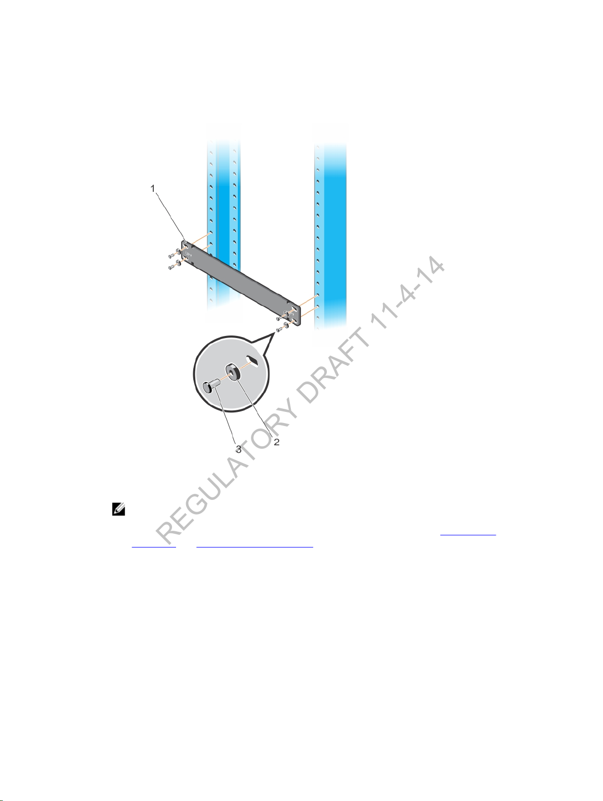
3. Hold the rack bar so that the smooth side faces outward and the arrows point upward. The smooth
REGULATORY DRAFT 11-4-14
side of the bar faces outward. Attach the bar to the rack posts using the mounting screws and
washers (items 2 and 3 in Figure 2) provided for the rack. Use the rack bar as a guide to mount the
chassis.
Figure 2. Installing a Rack Bar in a 2-Post Rack
: The installation procedure in this section describes how to install the C9010 in a rack
NOTE
using the rack bar provided in the base configuration package. For information about how to
use Dell ReadyRails or a rack mount tray to install the C9010 in a rack, see
ReadyRails and Installing a Rack Mount Tray.
4. Using a flat-head screwdriver, remove the bracket screws (item 2 in Figure 3), brackets (item 3 in
Figure 3), and thumb screws (item 4 in Figure 3) attached to each side of the chassis.
8
Installing Dell
Installing the Hardware
Page 9
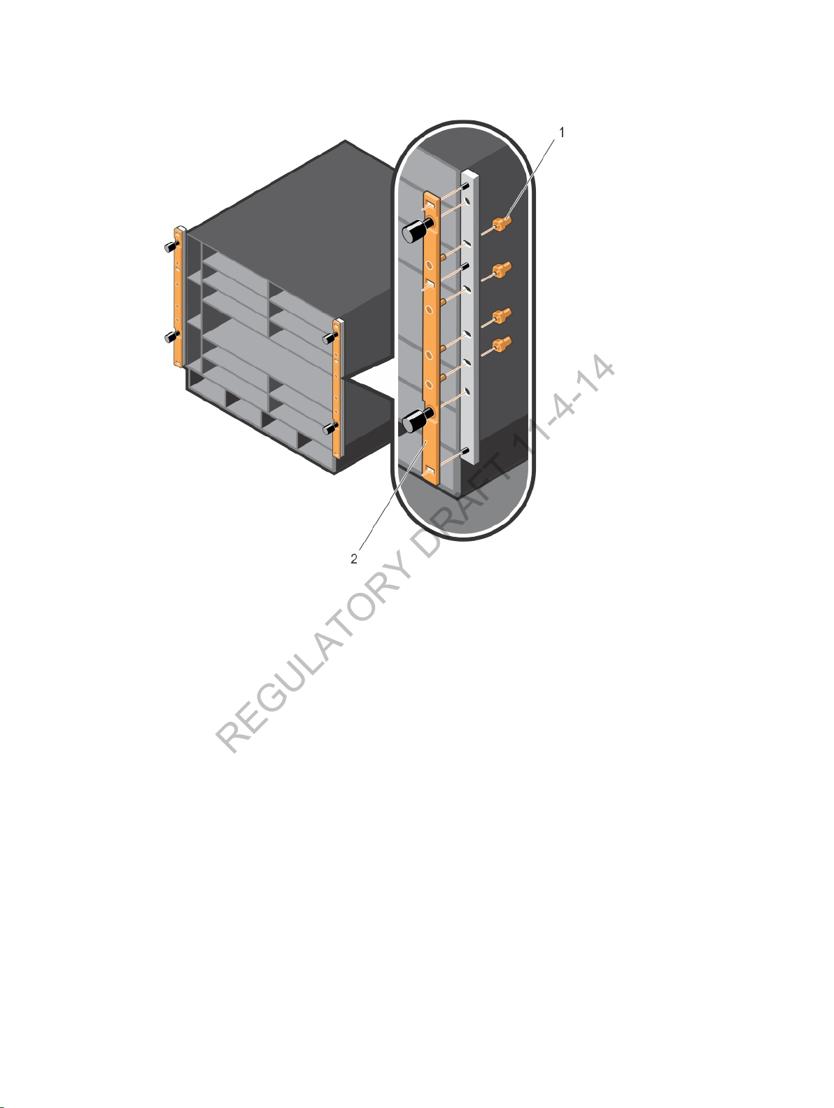
Figure 3. Removing Brackets from the Chassis
REGULATORY DRAFT 11-4-14
5. Use an equipment lift or ask two people to lift the chassis and align the rack-mount screw holes on
each flange of the chassis with the holes in the equipment rack (Figure 4). Rest the chassis on top of
the rack bar (or the rack tray or ReadyRails, if installed). Slide the chassis so that the holes in the side
flanges align with the holes in the rack posts. Tighten the two thumb screws (item 2 in Figure 4) and
four rack screws (item 3 in Figure 4) provided by the rack manufacturer on each chassis flange to
attach the chassis to the rack posts.
Installing the Hardware
9
Page 10
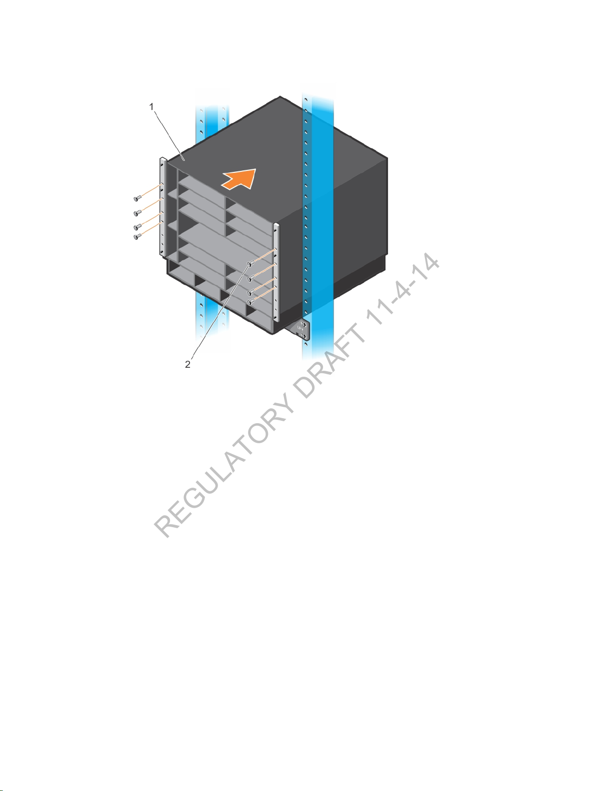
Figure 4. Mounting the Chassis into a 2-Post Rack
REGULATORY DRAFT 11-4-14
6. Verify that the chassis is securely installed in two rack posts and does not sag.
10
Installing the Hardware
Page 11
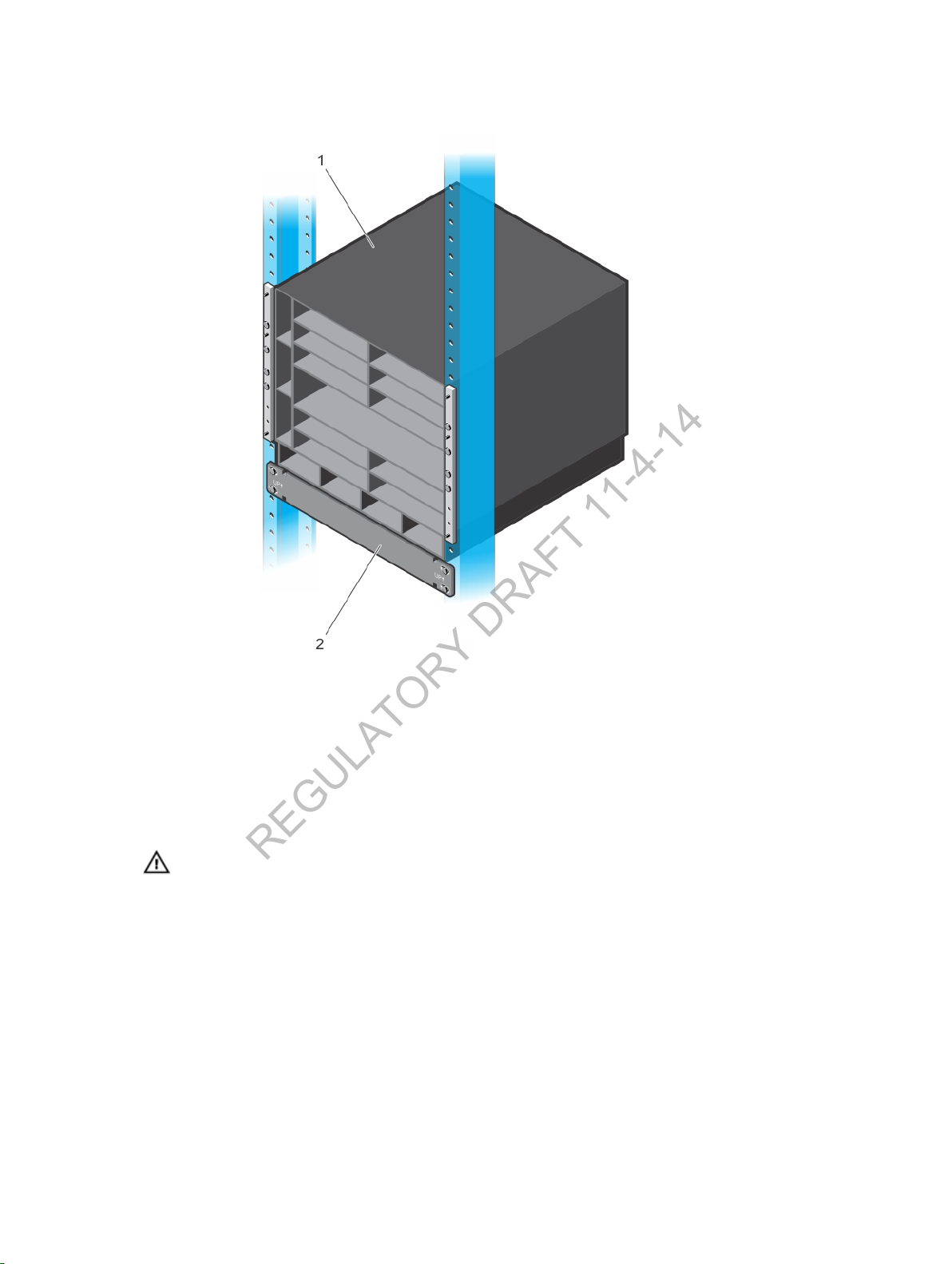
Figure 5. Chassis Installed in a 2-Post Rack
REGULATORY DRAFT 11-4-14
Installing the Chassis in a Four-Post Rack
You can install the C9010 chassis in a 4-post round- or square-hole rack by following the tool-less
procedure in this section or in a 4-post threaded-hole rack by following a tooled procedure. The
illustrations in this section show how to install the chassis in a 4-post square-hole rack using a tool-less
procedure.
WARNING
chassis into the rack before inserting the chassis components. Lift the C9010 chassis only from
the bottom. Lifting by the chassis shelves or power supply openings might damage the chassis.
: Use an equipment lift or pallet jack when lifting or moving the chassis. Install the
Installing the Hardware
11
Page 12
WARNING
REGULATORY DRAFT 11-4-14
precautions to ensure that the system remains stable. The following guidelines are provided to
ensure your safety:
• If your chassis is the only unit in the rack, mount it at the bottom of the rack.
• When mounting this unit in a partially filled rack, load the rack from the bottom to the top with
• If the rack is provided with stabilizing devices, install the stabilizers before mounting or servicing
1. Determine the height at which you want to mount the chassis in the equipment rack.
2. (Optional) If you are using a Dell ReadyRails kit, install the rails as described in Installing Dell
ReadyRails. If you are using a rack mount tray, refer to Installing a Rack Mount Tray. Then continue
with Step 4.
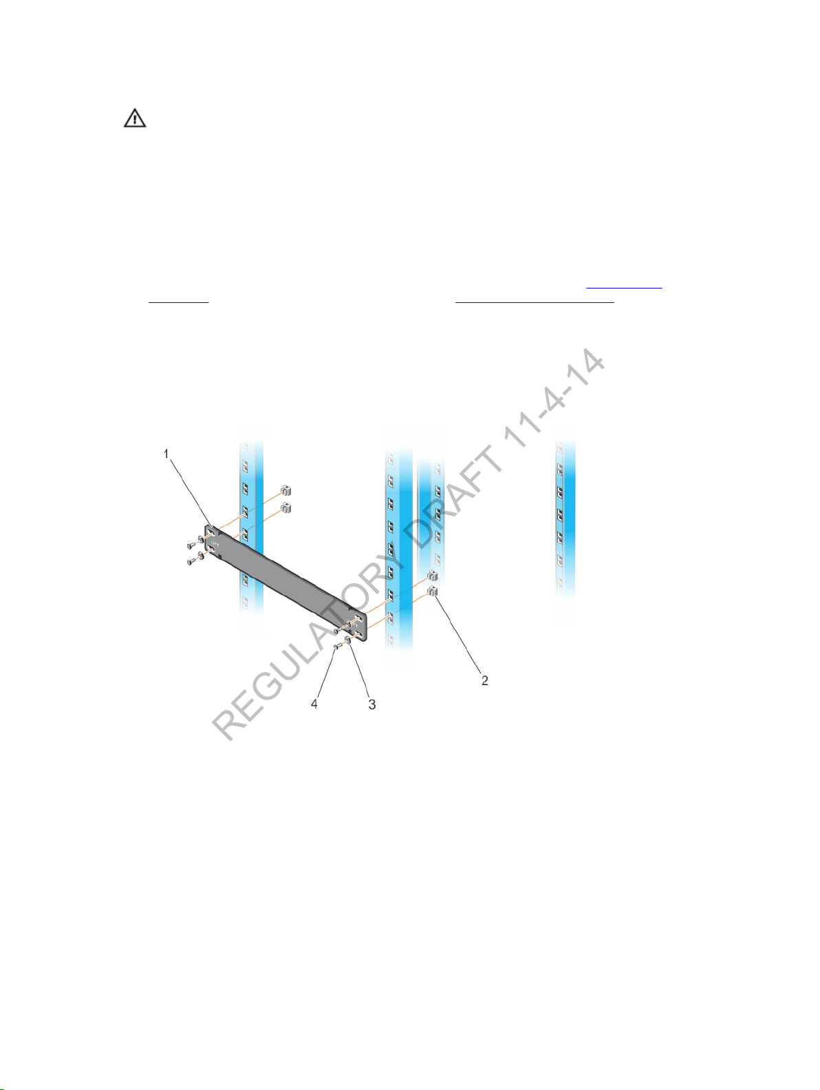
3. Hold the rack bar so that the smooth side faces outward and the arrows point upward. The smooth
side of the bar faces outward. Attach the bar to the two, front rack posts using the mounting screws,
washers, and cage nuts provided by the rack manufacturer (items 2, 3, and 4 in Figure 6). First clip
each cage nut into a post; then tighten each screw to secure the rack bar to the posts. Use the rack
bar as a guide to mount the chassis.
: To prevent bodily injury when mounting or servicing this unit in a rack, take special
the heaviest component at the bottom of the rack.
the unit in the rack.
Figure 6. Installing a Rack Bar in a 4-Post Rack
4. Use an equipment lift or two people to align the chassis rack-mount holes with the equipment rack
holes. Rest the chassis on top of the rack bar (or the rack tray or ReadyRails, if installed). Insert four
cage nuts (provided by the rack manufacturer) into the front rack posts at the desired height (item 3
in Figure 7). Install the lower cage nut 3 RUs above the rack bar; install the upper cage nut 5 RUs
above the lower cage nut.
12
Installing the Hardware
Page 13
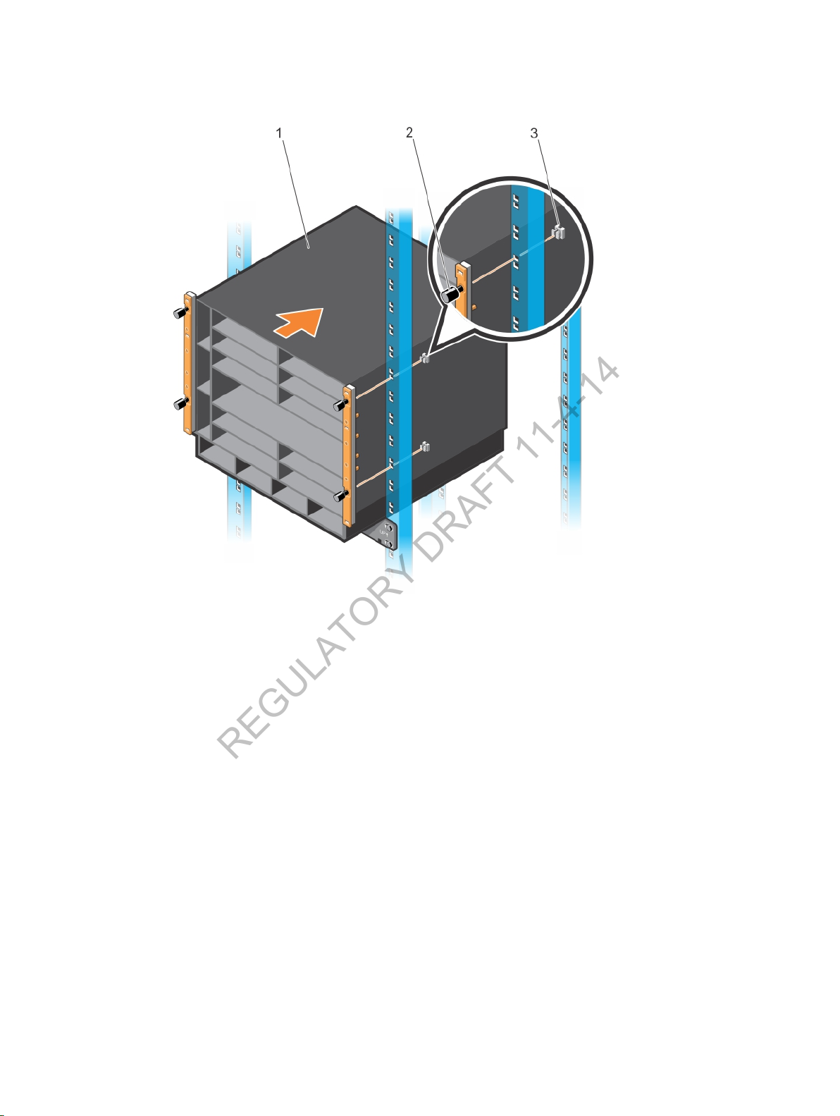
Figure 7. Aligning Rack-Mount Holes with 4-Post Rack Holes
REGULATORY DRAFT 11-4-14
5. Lift and slide the chassis so that the holes on the chassis flanges touch the holes in the rack posts.
Tighten the four thumb screws on the flanges into the cage nuts to secure the chassis on the front
posts (Figure 8).
Installing the Hardware
13
Page 14
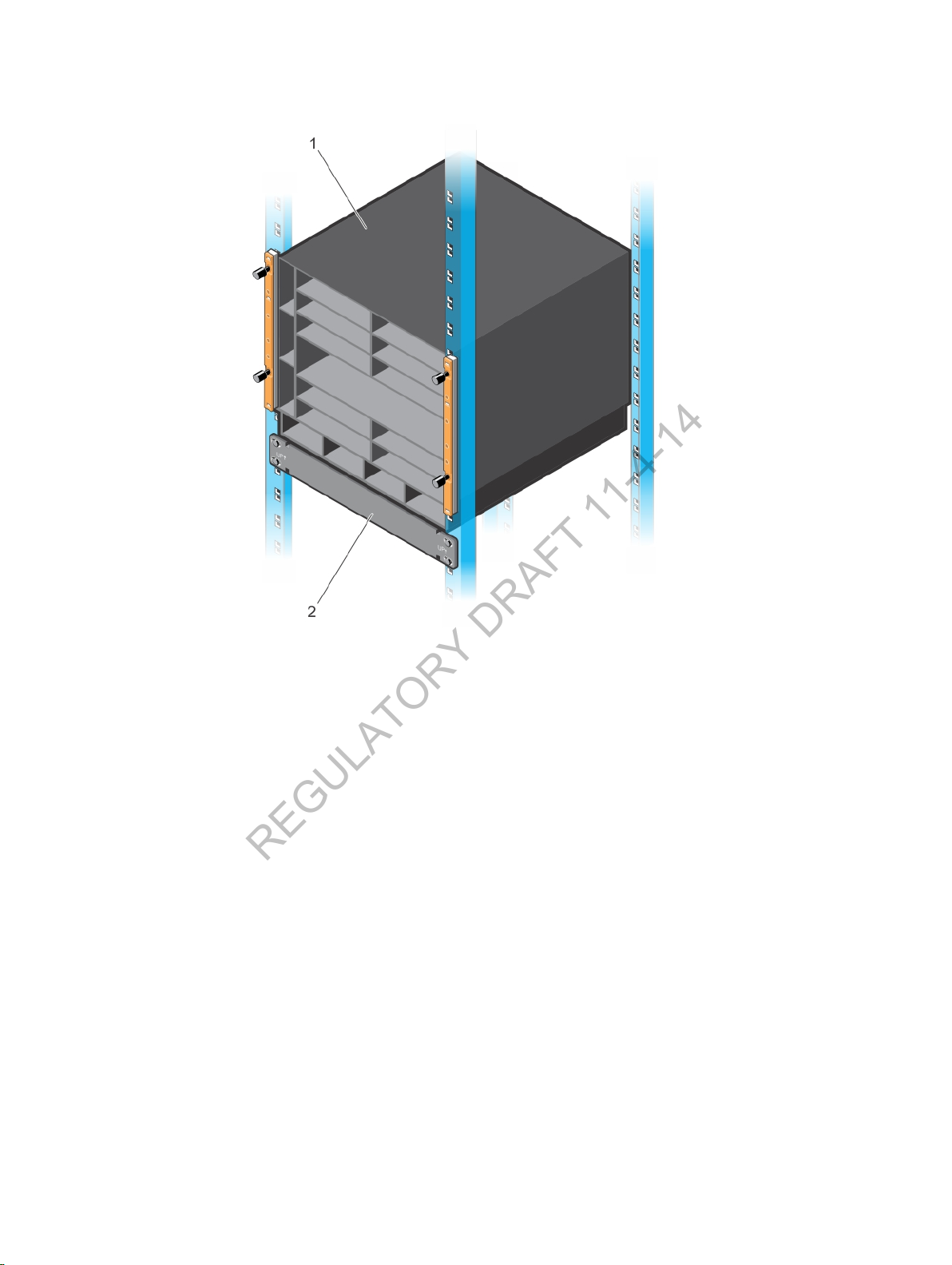
Figure 8. Chassis Installed in a 4-Post Rack
REGULATORY DRAFT 11-4-14
Using Dell ReadyRails (Optional)
Dell Networking offers the Dell ReadyRails rack mounting system as an option to ease the installation of a
switch in a 2-post or 4-post rack. You must purchase a ReadyRails kit as a separate item; it is not shipped
with the C9010 switch.
You can install Read Rails using a tool-less method in a non-threaded-hole rack or a tooled method in a
threaded-hole rack. Dell ReadyRails support a rack length of 24 to 30 inches. The ReadyRails kit consists
of:
• Chassis rails for the left and right sides of the C9010 chassis (items 1 and 2 in Figure 9)
• Left and right rail brackets that fit into the front rails on 2-post racks (items 3 and 4 in Figure 9)
• Front rails for the left and right posts of 2- and 4-post racks (items 5 and 6 in Figure 9)
• Rear rails that fit into the left and right front rails on 4-post racks (items 7 and 8 in Figure 9)
14
Installing the Hardware
Page 15
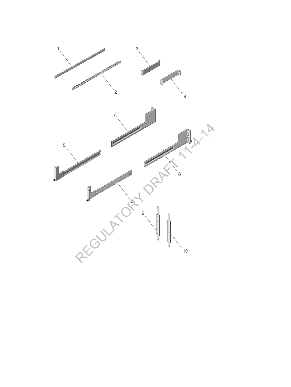
Figure 9. Dell ReadyRails for 2- and 4-Post Racks
REGULATORY DRAFT 11-4-14
1. Left chassis rail 2. Right chassis rail
3. Left ReadyRail bracket for 2-post racks 4. Right ReadyRail bracket for 2-post racks
5. Left front rail with attached subassembly and
thumb screw
7. Rear rail that fits into the left front rail 8. Rear rail that fits into the right front rail
9. Spacer 10. Spacer
6. Right front rail with attached subassembly
and thumb screw
Installing the Hardware
15
Page 16
Installing ReadyRails: Tool-less Method for a Non-Threaded-Hole Rack
REGULATORY DRAFT 11-4-14
To install ReadyRails using a tool-less method in a non-threaded 4-post rack:
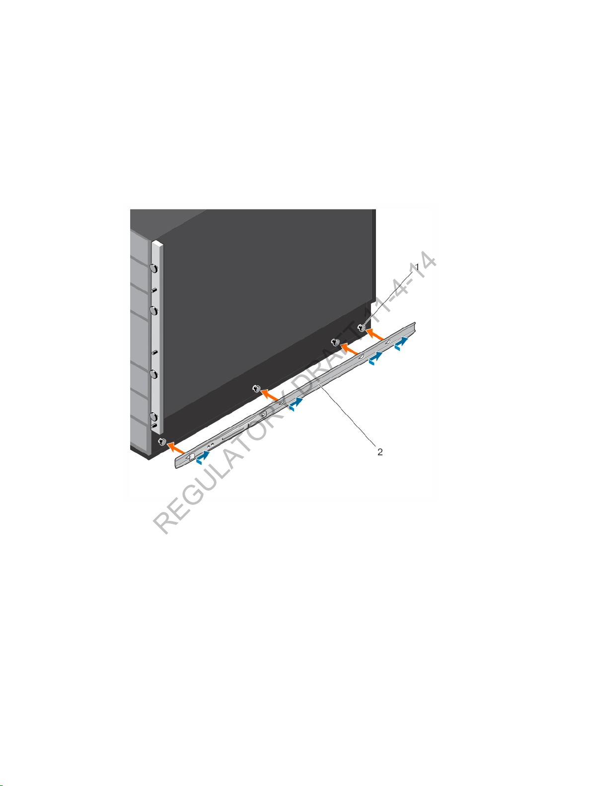
1. Attach the chassis rails on the right and left sides of the chassis.
• Remove the two chassis rails from the Dell ReadyRails kit.
• Align the holes on the right and left chassis rails with the screws at the bottom of each side of the
chassis (orange arrows and item 1 in Figure 10).
• Press each chassis rail over the screws and slide it backwards (towards the back of the chassis) so
that it snaps securely into place (blue arrows and item 2 in Figure 10).
Figure 10. Installing Chassis Rail for Toolless Ready Rail Installation
2. Attach a spacer to the back of each chassis flange as shown in Figure 11. The spacers allow the
flanges to be attached flush to each rack post.
Place each spacer over the four pins at the back of each chassis flange. Then slide each spacer down
so that it locks into place and is flush with the flange.
16
Installing the Hardware
Page 17
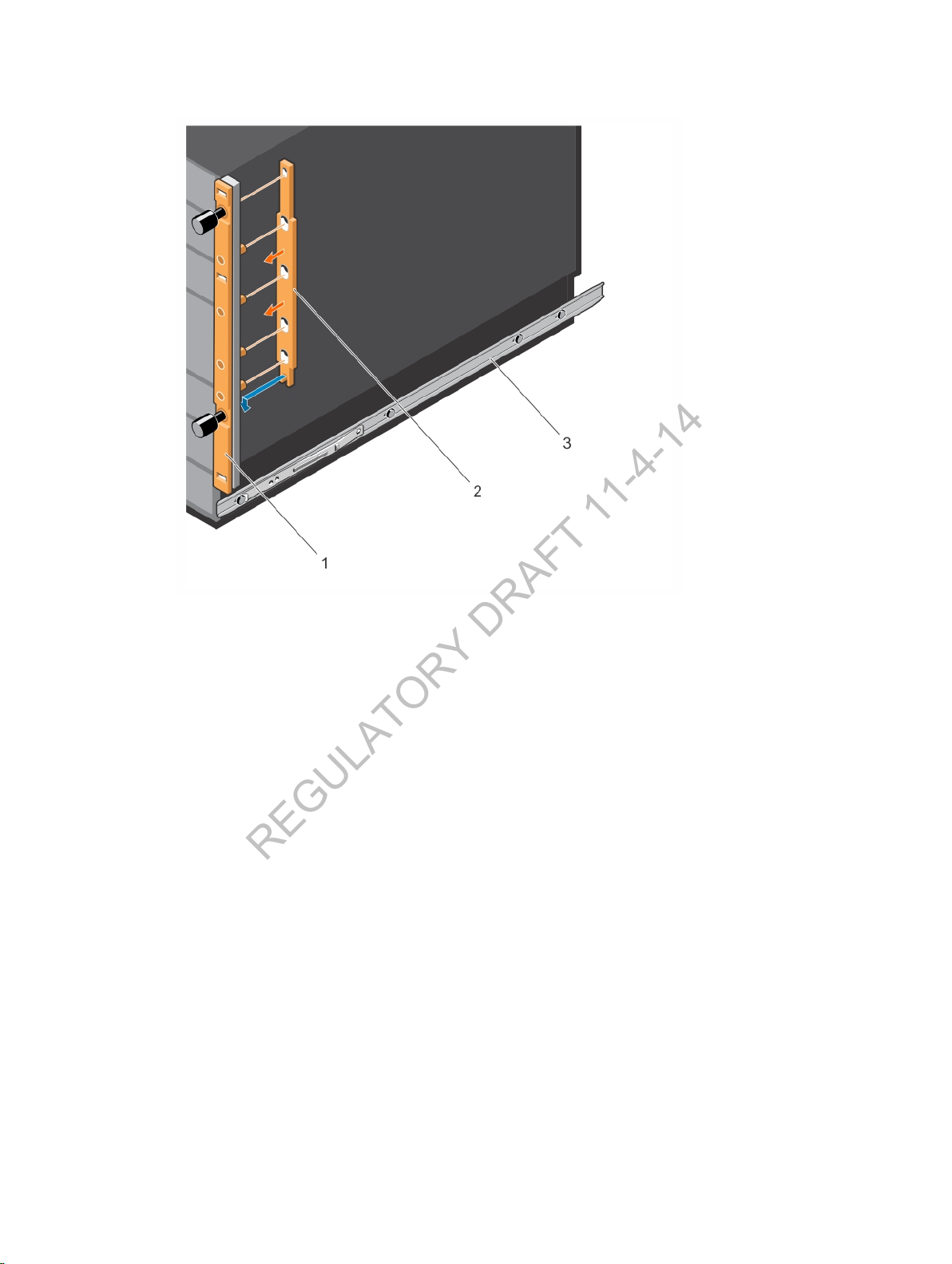
Figure 11. Installing a Spacer on a Chassis Flange
REGULATORY DRAFT 11-4-14
3. Attach a Ready rail to the right and left sides of the rack at the desired height.
a. Remove the front and rear parts of the left 4-post rail from the Dell ReadyRails kit and slide the
parts together.
b. Position the left rail so that the rail end labeled FRONT faces inward.
c. Align the end of the left rail with holes on the left rack post in the desired U spaces (item 1 in
Figure 11). Install a cage nut (item 2 in Figure 11) in the post at the height of the thumb screw.
Gently press the rail end into the rack post and tighten the thumb screw in the cage nut to
secure the rail to the post.
d. Align the back end of the left rail (item 3 in Figure 11) until it fully seats in the back post holes
(item 2 in Figure 11).
e. Repeat Steps (a) through (d) to install the right rail.
f. To remove or reposition a rail, loosen the thumb screw on each end and unseat the rail from
the rack.
Installing the Hardware
17
Page 18
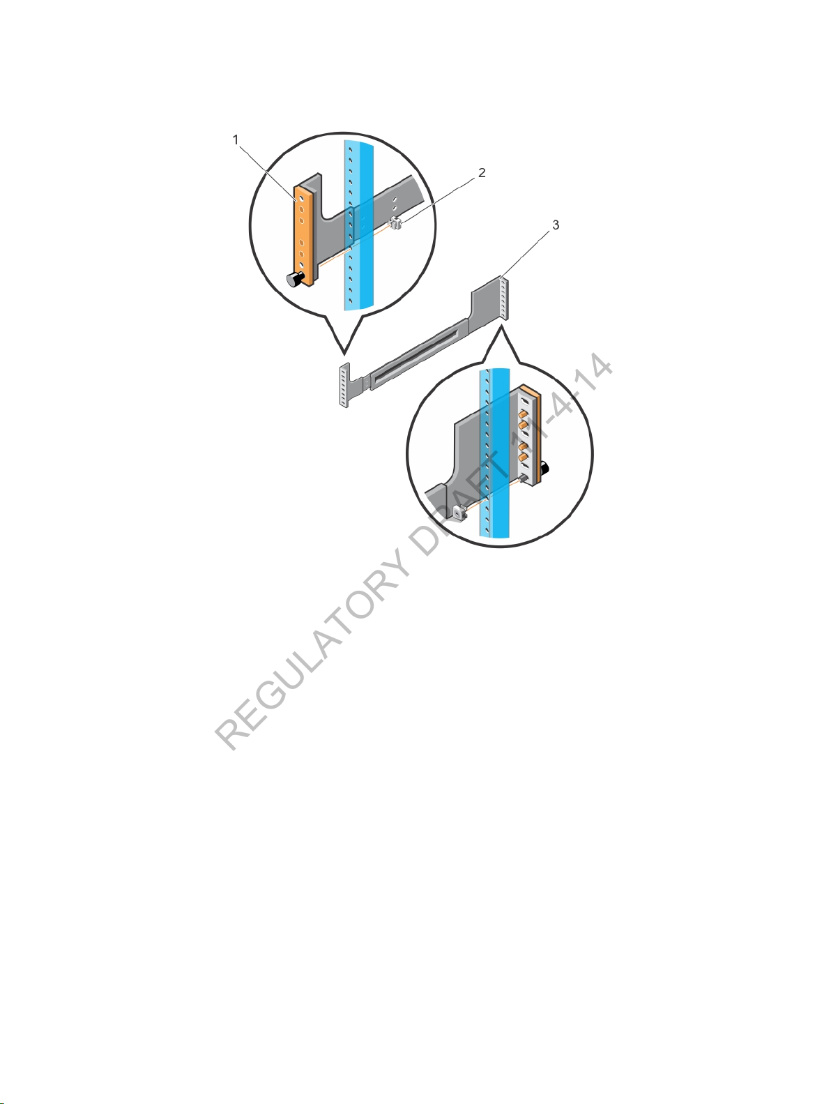
Figure 12. Installing Tool-less Rails in a Non-Threaded-Hole Rack
REGULATORY DRAFT 11-4-14
4. Lift the chassis and slide it into the rails installed in the rack (Figure 12). Install two cage nuts in each
post at the desired height of the two thumb screws on each flange. Tighten the thumb screws in the
cage nuts to secure the chassis to the rack.
18
Installing the Hardware
Page 19
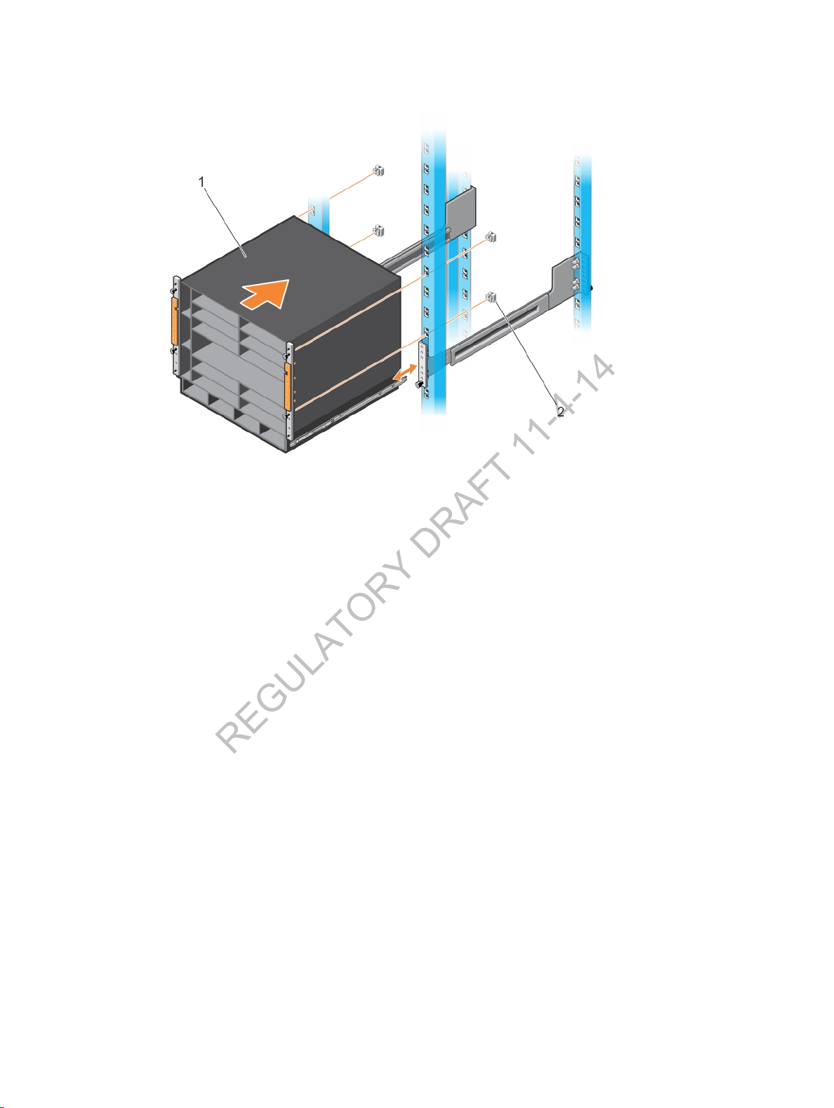
Figure 13. Installing the Chassis with ReadyRails in a Non-Threaded-Hole Rack
REGULATORY DRAFT 11-4-14
Installing ReadyRails: Tooled Method for a Threaded-Hole Rack
To install ReadyRails using a tooled method in a threaded-hole 2- or 4-post rack:
1. Locate the front rack rails in the Dell ReadyRails kit. For a 2-post rack, locate the left and right rail
brackets (items 5 and 6 in Figure 9).
• For a 2-post rack, take out the left and right rail brackets (items 3 and 4 in Figure 9) and slide
them into the front rails.
• For a 4-post rack, take out the left and right rear rails (items 7 and 8 in Figure 9) and slide them
into the front rails.
2. Remove the pins from the front and rear of each rail using a flat-tipped screwdriver. Pull on the latch
subassemblies to remove them from the rail brackets (items 1 and 2 in Figure 13).
Installing the Hardware
19
Page 20
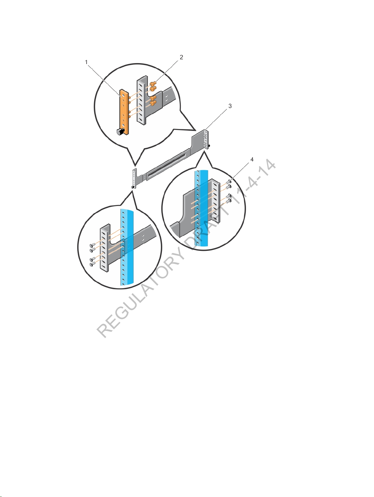
Figure 14. Installing Tooled Rails in a Threaded-Hole Rack
REGULATORY DRAFT 11-4-14
3. Attach the front of each rail to the front rack posts using the screws provided with the rack.
On a 4-post rack, slide each rail backward so that they seat into the back post holes at the desired
height. Attach each rail to a rear post using four screws provided with the rack (item 4 in Figure 13).
4. Lift the chassis and slide it into the rails installed in the rack (Figure 14). Tighten the two thumb
screws and four rack screws (item 5 in Figure 14) on each flange to secure the chassis to the rack.
On a 2-post rack, slide each rail bracket (item 4 in Figure 14) forward to the post. Tighten two screws
(item 3 in Figure 14) to secure the bracket to each post.
20
Installing the Hardware
Page 21
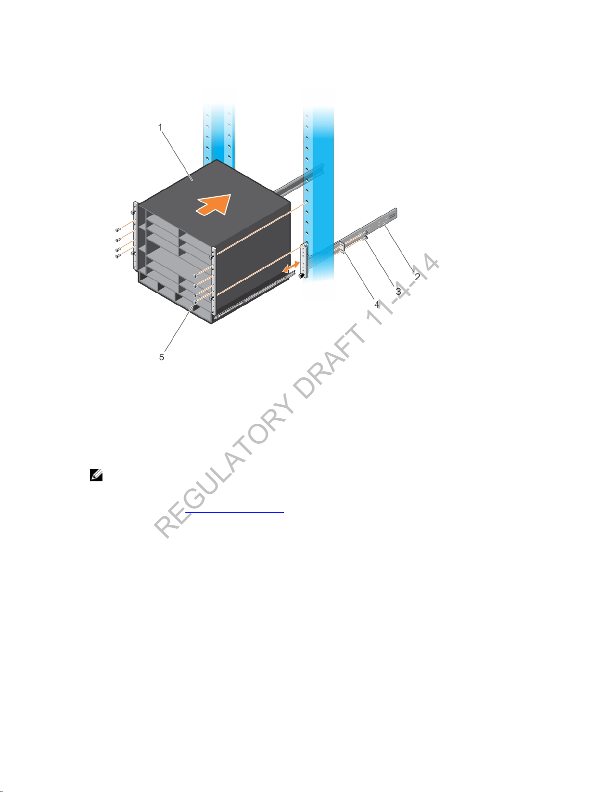
Figure 15. Installing the Chassis with ReadyRails in a Threaded-Hole Rack
REGULATORY DRAFT 11-4-14
Using a Rack Mount Tray (Optional)
You can also use a rack mount tray to install the C9010 switch in a 2- or 4-post rack. You must purchase
the tray as a separate item; it is not shipped with the C9010 switch.
: If the use of a rack bar or Dell ReadyRails does not satisfy your C9010 installation
NOTE
requirements, Dell Networking recommends using a rack mount tray to support the weight of a
C9010 switch in a 4-post rack. For information about the chassis weight and other technical
specification, see
To install a rack mount tray in a 2- or 4-post rack, follow the instructions provided with the tray kit.
Decide on the desired height at which you want to mount the switch in the rack. Position the tray at that
height and tighten it to the rack posts using the screws shipped with the tray (items 1 to 4 in Figure 15).
Technical Specifications.
Installing the Hardware
21
Page 22
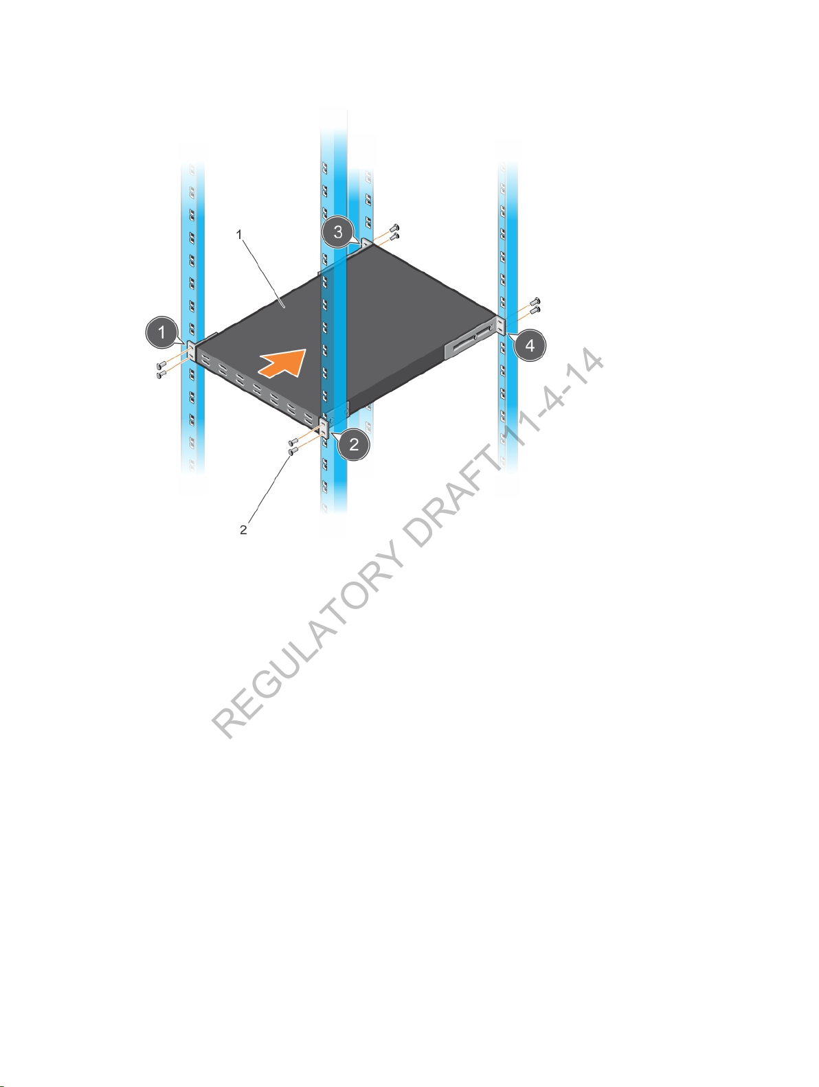
Figure 16. Example of a Mount Rack Tray in a 4-Post Rack
REGULATORY DRAFT 11-4-14
Securing the Chassis Ground
After you mount the chassis in a rack, secure the chassis ground as follows:
1. Locate the chassis ground lug nut and holes on the bottom left side (facing you) of the chassis.
2. Attach a grounding cable to the chassis lug by inserting a 6-gauge cable (item 1 in Figure 16). Crimp
the lug (item 2 in Figure 16) using a wire crimping tool so that it holds the cable securely.
22
Installing the Hardware
Page 23
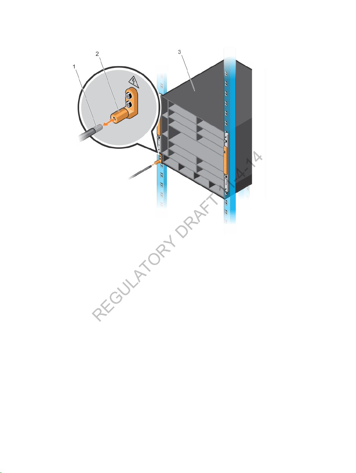
Figure 17. Grounding the Chassis
REGULATORY DRAFT 11-4-14
3. Connect the opposite end of the grounding cable to the nearest appropriate grounding post in your
facility.
Installing a Fan Tray
The C9010 switch requires three fans for normal operation. Three field-replaceable fan trays are shipped
with the base configuration. To ensure proper temperature and airflow control, the fan tray must always
be installed and operating properly.
1. Slide the first fan tray into the fan slot 0, the uppermost fan slot (item 2 in Figure 17).
2. Gently push the front of the tray until it clicks into place. The fan tray should be flush with the
chassis.
3. Repeat Steps 1 and 2 to install a second fan tray into fan slot 1, the middle fan slot.
4. Repeat Steps 1 and 2 to install a third fan tray into fan slot 2, the bottommost fan slot.
5. To remove a fan tray, press the orange button on the handle (item 1 in Figure 17) and pull out the fan.
Installing the Hardware
23
Page 24
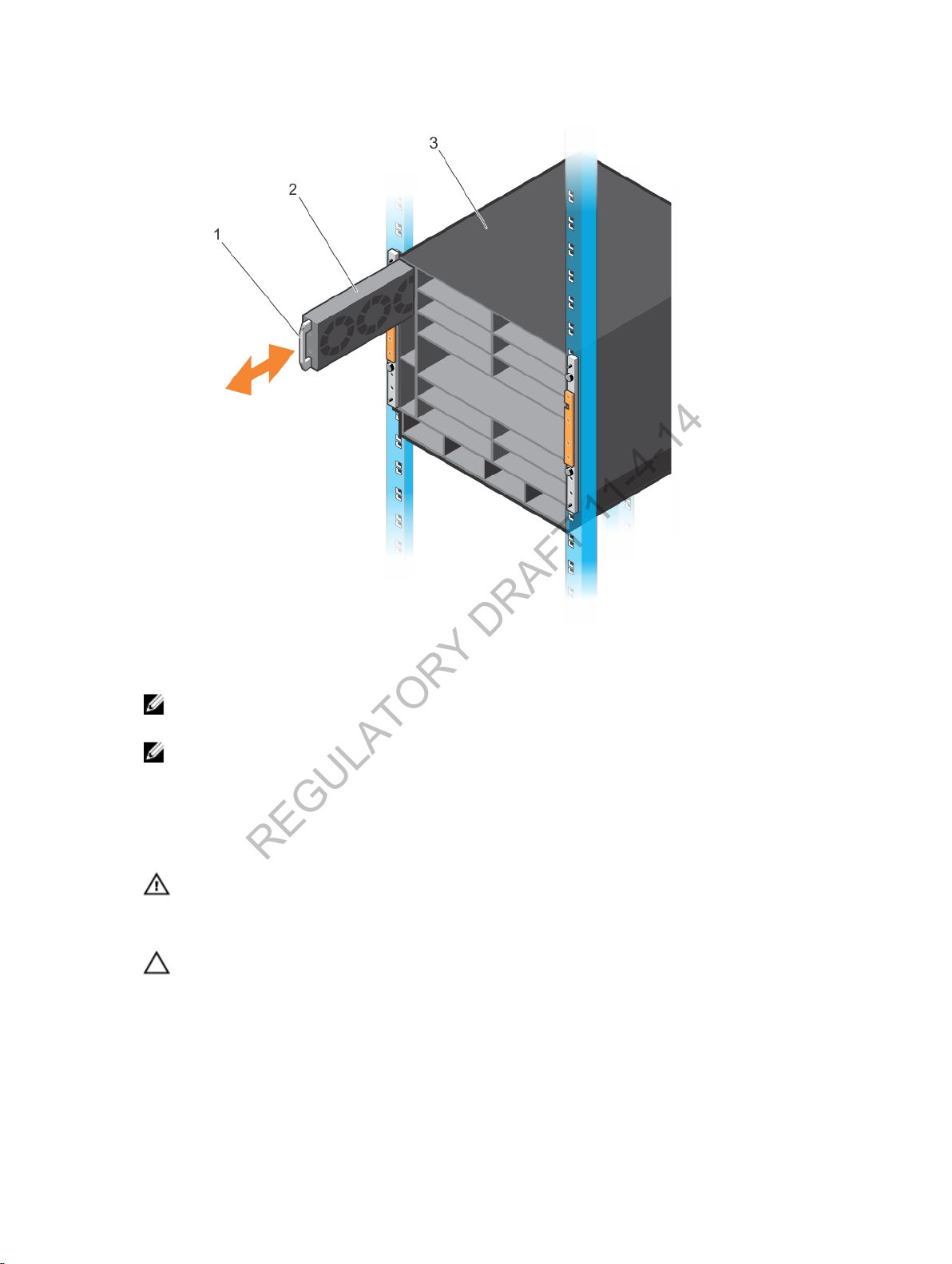
Figure 18. Installing a Fan Tray
REGULATORY DRAFT 11-4-14
: The system does not have an air filter; ensure that you regularly clean the installation site and
NOTE
the chassis.
: The fan tray light-emitting diode (LED) remains lit when the chassis is powered up and the
NOTE
fan tray is functioning properly.
Installing RPMs and Line Cards
The C9010 chassis supports up to ten line cards and two route processor modules.
WARNING
RPM or a line card. Always place RPMs and line cards on an antistatic surface or in an antistatic
bag when not in use or when carrying them. ESD damage can occur when components are
mishandled. Do not use the ejector handle to carry an RPM or line card.
CAUTION
the RPM or linecard, fully engage the locking mechanism; without the locking mechanism
engaged, you can damage the lower linecard when you insert it.
: Always wear an ESD-preventive wrist or foot-heel ground strap when handling an
: Unlock the levers before inserting an RPM or line card into the chassis. After you insert
24
Installing the Hardware
Page 25
Installing an RPM
REGULATORY DRAFT 11-4-14
Install the fan trays before you install RPMs in a C9010 switch.
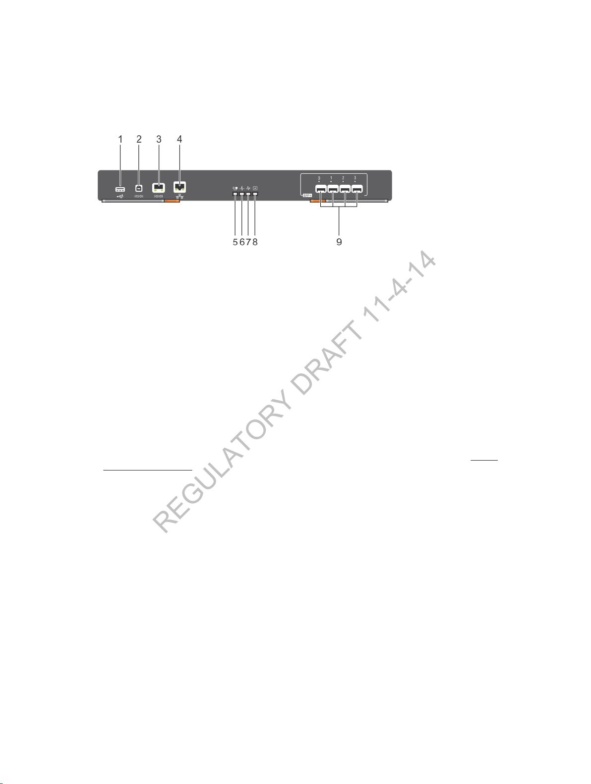
Figure 19. C9010 Route Processor Module
1. USB-A port 2. USB-B console port
3. RJ-45 console port 4. 10/100/1000Base-T RJ-45 management
5. RPM Master Indicator LED 6. RPM Module Status LED
7. Fan Status LED 8. PSU Status LED
9. 10G SFP+ Port Status LEDs
port
Before you install an RPM in the C9010 chassis, review these guidelines:
• Although the C9010 switch can operate with one RPM, Dell Networking recommends that you use
two RPMs.
• One RPM provides 48 Gigabits of bandwidth to each linecard.
• Two RPMs provide 96 Gigabits of bandwidth to each linecard.
• If the C9010 operates with only one RPM, you must install the RPM in RPM slot 0. Refer to C9010
Hardware Description for the location of RPM slot numbers.
• To control airflow for adequate system cooling, personal safety, and EMI containment during
operation, install blanks in any empty RPM slots. Install operational modules or blanks in all RPM slots.
Always replace cards and blank panels immediately.
• The blank panels for RPMs and linecards are different sizes (RPM blanks are smaller); be sure you
install blank panels in the correct slots.
• RPMs are hot-swappable. The C9010 supports high availability.
• If your system uses two RPMs, both RPMs must have the same software image.
1. Open the left and right ejector levers (item 1 in Figure 19) on the RPM by pressing in the orange tab
(item 2 in Figure 19) and rotating it to the right so that both levers snap into the open position.
Installing the Hardware
25
Page 26
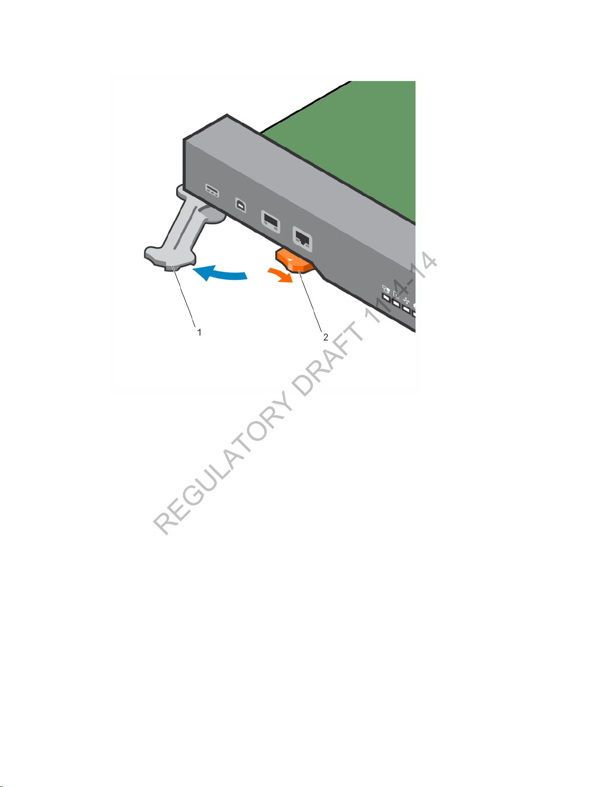
Figure 20. Extending the RPM Ejector Levers
REGULATORY DRAFT 11-4-14
2. Hold the card assembly by the metal carrier edges. Avoid touching the printed circuit board and
connector pins.
3. The arrow in RPM slot 0 (item 2 in Figure 20) identifies the slot in which you must insert the first RPM.
Align the card with the guide (item 2 in Figure 20) and gently slide it into the slot by holding the two
ejector levers in the fully open position and pushing the card forward. You should feel the backplane
connectors on the RPM engage with the chassis backplane.
26
Installing the Hardware
Page 27
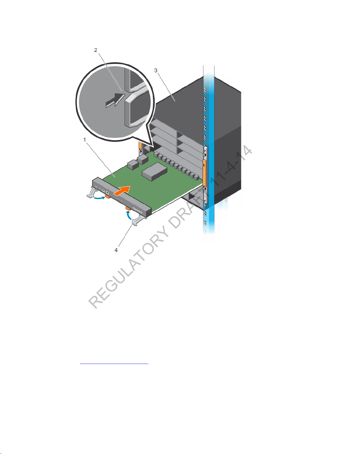
Figure 21. Inserting the First RPM in the Chassis
REGULATORY DRAFT 11-4-14
4. Push in the levers until the thumb tabs pop up and the card is fully inserted in the slot. The ejector
levers hide under the card.
5. If the C9010 uses two RPMs, insert the second RPM into RPM slot 1 below the first RPM by following
Steps 1 to 4.
6. If the C9010 uses only one RPM, install a blank panel to cover RPM slot 1. Secure the panel with the
screws provided.
Installing a Line Card
Install the fan trays before you install line cards in a C9010 switch.
Before you install line cards, review these guidelines:
• On the C9010, line-card slots are labeled 0 to 9. You can insert any linecard into any line-card slot.
Refer to C9010 Hardware Description for the location of line-card slot numbers.
• To control airflow for adequate system cooling, personal safety, and EMI containment during
operation, install blanks in any empty line-card slots. Install operational modules or blanks in all linecard slots. Always replace cards and blank panels immediately.
Installing the Hardware
27
Page 28
• The blank panels for RPMs and linecards are different sizes (line-card blanks are smaller); be sure you
REGULATORY DRAFT 11-4-14
install blank panels in the correct slots.
• C9010 line cards are hot-swappable. The C9010 supports high availability.
• Do not press on the port connectors when you install a line card.
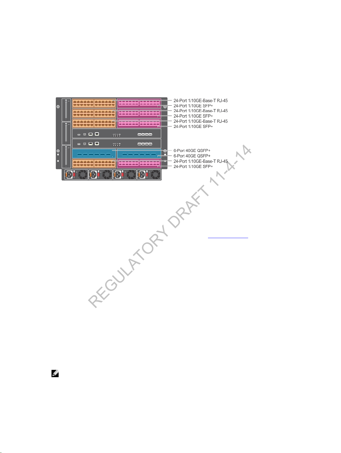
Figure 21 shows the types of line cards supported in the C9010.
Figure 22. Example of C9010 with Line Cards Installed
1. On a full-width line card, open the left and right ejector levers by pressing the orange thumb tabs.
The two ejectors levers should spring open.
On a half-width line card, there is only one ejector lever; open the left lever in the same way by
pressing the orange thumb tab so that the lever pops out. See Installing an RPM for the location of
the thumb tabs and ejector levers.
2. Hold the card assembly by the metal carrier edges. Avoid touching the printed circuit board and
connector pins.
3. You can insert a line card into any line-card slot. Align the card with the guide in the chassis slot.
While holding the ejector lever, press on any convenient edge of the front panel to slide the card
until you feel the backplane connectors engage the chassis backplane. Be sure not to press on the
port connectors.
4. Push in the lever until the thumb tab pops up and the card is fully inserted in the slot.
5. Repeat Steps 1 to 4 to insert additional line cards in the chassis.
6. Install a blank panel in all slots that do not have a line card. Press the orange tab on a blank to open
the ejector lever. Holding the lever, insert the blank to cover the open slot. Push in the lever to
secure the blank in place.
Installing a Power Supply
The C9010 has four power supply slots at the bottom of the front of the chassis. The C9010 supports
only an AC power supply. The power supply is rated as 2900W at 200~240Vac and 1450W at
100~120Vac.
: If a power supply fails, replace it as soon as possible. C9010 power supply units (PSUs) are
NOTE
hot-swappable.
28
Installing the Hardware
Page 29
PSU Installation Guidelines
REGULATORY DRAFT 11-4-14
• The C9010 requires the use of at least one power supply for normal operation. Dell Networking
recommends using additional power supplies for redundancy depending on the maximum system
power that is required and the local power grid voltage (100~120Vac/200~240Vac).
• C9010 power supplies do not support a combination of power grid types. For example, all PSUs in a
C9010 should be powered either by 200~240Vac or 100~120Vac, but not both. Do not mix utility
input.
• To protect against high-voltage shock, install a power supply blank in all unused power supply slots.
• Connect the AC power supply to the appropriate branch circuit protection as defined by your local
electrical codes.
• Verify that the remote power source complies with the system input power specifications.
WARNING
to your system until you install the power supplies, fan tray, route process modules (RPMs) and
linecards.
WARNING
protection. Dell Networking recommends using a fuse or circuit breaker of 120 VAC, 20 A U.S.
(240 VAC, 20 A international) for AC input on each power supply to ensure its maximum power
capacity.
WARNING
disconnecting device in the building installation. Ensure you locate and install the device near the
equipment and that it is easily accessible.
WARNING
power supply configuration the C9010 supports. As a safety precaution, do not install more than
the recommended maximum number of PSUs, as this causes high leakage current. Install blank
panels in all unused PSU slots.
: Use only the AC power cord supplied with the AC power supply. Do not supply power
: The C9010 relies on the building's installation for short-circuit (overcurrent)
: The C9010 does not have a main disconnect device. You must provide a suitable
: The C9010 operates in either of two voltage ranges. The following lists the different
PSU Installation Procedure
1. Verify that the PSU switch is in the OFF (down) position.
2. Slide the first power supply into the left-most power supply slot (PSU 0) until the latch (item 1 in
Figure 22) snaps in place. Refer to C9010 Hardware Description for the location of PSU slot numbers.
3. Plug an AC power cord into the front of the power supply.
4. Plug the power cord into an AC power outlet.
5. Repeat Steps 1 to 4 to install additional AC power supplies of the same wattage. Install each
additional power supply in the left-most available PSU slot; for example, install the second power
supply in PSU slot 1, the third power supply in PSU slot 2, and the fourth power supply in PSU slot 3.
6. Install a blank to cover any open PSU slot.
Installing the Hardware
29
Page 30
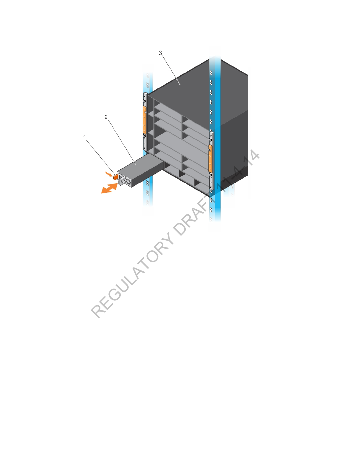
Figure 23. Installing the First Power Supply
REGULATORY DRAFT 11-4-14
Installing the Cable Management System
You can install a cable management system on the front of the chassis to organize network cables and
minimize the obstruction from cables when you insert, remove, and view chassis components. Using the
cable management system, you can attach the maximum number of cables in C9010 line-card ports. The
cable management system consists of two brackets (items 1 and 2 in Figure 23) and is shipped as part of
the C9010 base configuration.
30
Installing the Hardware
Page 31
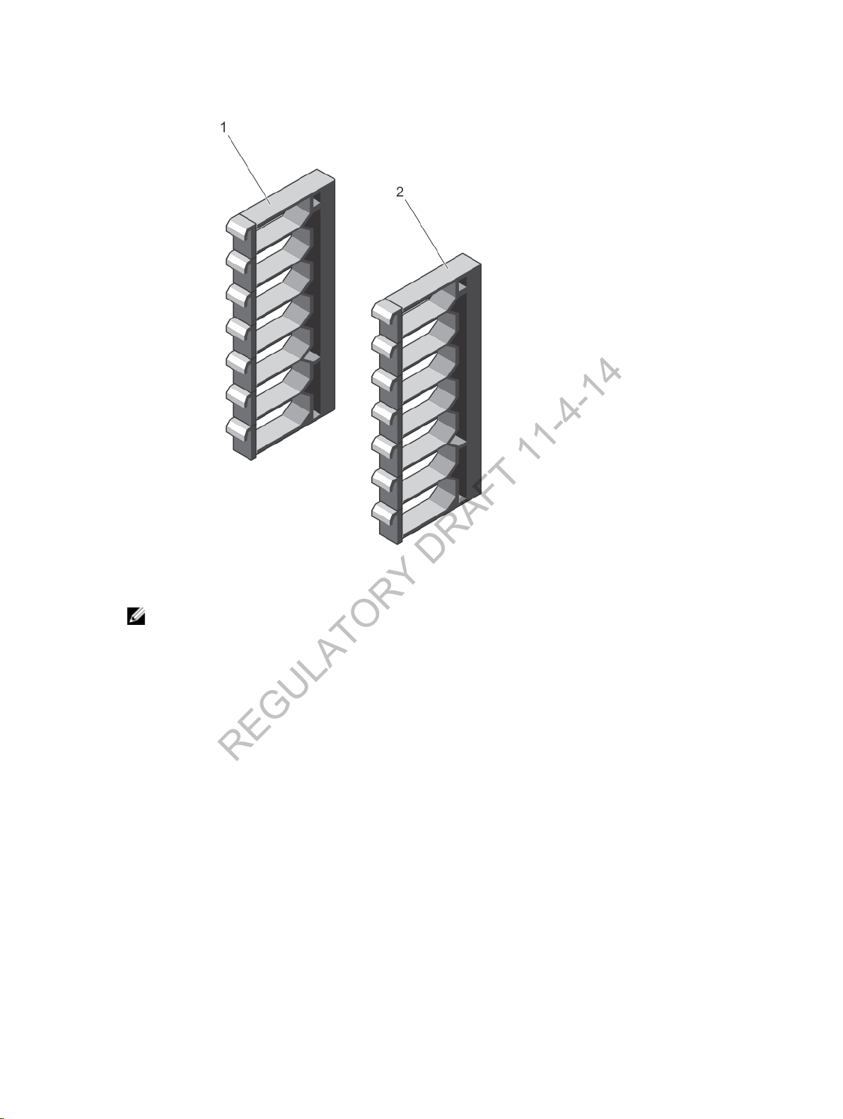
Figure 24. Cable Management System
REGULATORY DRAFT 11-4-14
: Dell Networking recommends that you install the cable management system after you install
NOTE
the chassis in a rack and all chassis components in the chassis.
To install the cable management system, mount both brackets on the right and left sides of the chassis.
1.
Align the openings on the inside of a bracket with the pins (item 1 in Figure 24) and thumb screws on
each chassis flange.
Installing the Hardware
31
Page 32
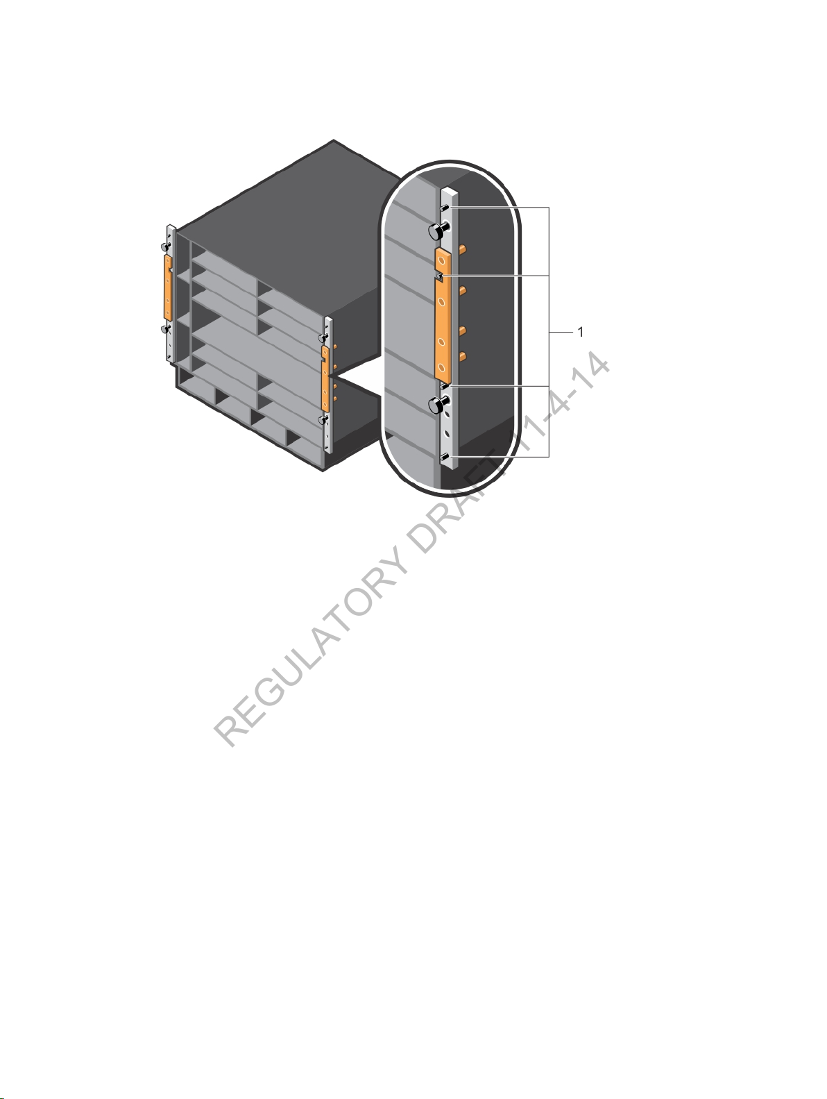
Figure 25. Installing Cable Management Brackets on the Chassis Flanges
REGULATORY DRAFT 11-4-14
2. Press the bracket forward so that the bracket holes cover the pins and thumb screws on the flanges
(item 1 in Figure 25). The bracket locks in place as you press it forward.
32
Installing the Hardware
Page 33
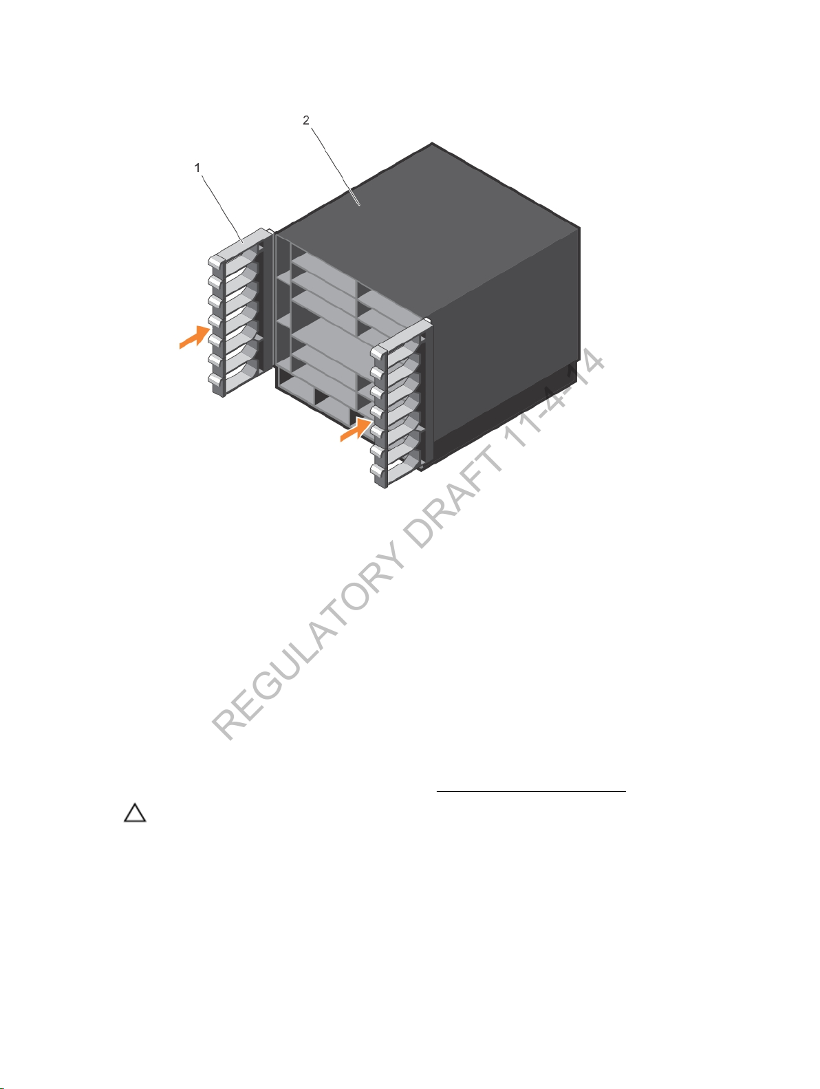
Figure 26. Cable Management Brackets Installed on Chassis
REGULATORY DRAFT 11-4-14
3. To open part of a cable bracket, pull one of the latches forward so that it swings down.
4. To remove a cable bracket, push up the blue button located in the center of a bracket to release it.
When you cable C9010 ports, be sure not to interfere with the airflow from the ventilation holes on the
right and left sides of the chassis.
Do not remove the cable management brackets with installed cables. First unplug and remove all cables,
then remove the brackets.
Installing the QSFP+ and SFP+ Optics
The C9010 switch may use 40G QSFP+ and/or 1/10G SFP+ optical ports. You can use a breakout cable in
a 40G QSFP+ port to split it into 4 SFP+ optical ports.
For a list of supported optics, refer to the data sheet at [Add link from Harish/Mike Chow].
CAUTION: ESD damage can occur if the components are mishandled. Always wear an ESDpreventive wrist or heel ground strap when handling the switch and its components.
Installing the Hardware
33
Page 34
WARNING
REGULATORY DRAFT 11-4-14
protection. Never look directly into the end of a terminated or unterminated fibre or connector
as it may cause eye damage.
1. Position the optic so it is in the correct position. The optic has a key that prevents it from being
inserted incorrectly.
2. Insert the optic into the port until it gently snaps into place.
: When working with optical fibres, follow all the warning labels and always wear eye
Powering Up the System
After you install the chassis with power supplies in a rack, supply power to the C9010.
Before Powering Up
Before you supply power to the chassis, Dell Networking recommends that you re-inspect your
equipment rack and chassis. Verify that:
• The equipment is properly secured to the rack.
• The equipment rack is properly mounted and grounded.
• The ambient temperature around the unit (which may be higher than the room temperature) is within
the limits specified for the C9010. For information about the supported temperature range and other
technical specification, see Technical Specifications.
• There is sufficient airflow around the unit.
• All protective covers are in place.
• The input circuits are correctly sized for the loads and that you use sufficient over-current protection
devices.
• Each AC power supply unit is correctly installed. A power plug is connected to each AC power
connector and the power cord is secure.
CAUTION
CAUTION
NOTE
up an AC power supply. You must order all other power cables separately.
NOTE
another power supply. Power supply units (PSUs) are field-replaceable.
: Do not power up the switch if no fan tray is installed.
: The switch has a high line-voltage requirement of minimum 200V.
: A country/region-specific AC power cable is included in the shipping container for powering
: If a power supply fails, you can replace it while the switch is running by hot-swapping
Power Up Sequence
To power up the switch:
1. Verify that the power source complies with the system input power requirements.
2. Energize the remote power source or outlet.
3. Toggle the switch on all AC power supplies to the ON (up) position.
4. The power supply LEDs show green. If these LEDs do not show green:
• Check that you properly installed the unit.
• Verify the power source.
• If you cannot verify the power supply, power off all modules and replace the unit.
5. The fan tray LED shows green (online). You are able to hear the air flowing through the chassis. If the
fans are not operating properly or air is not flowing through the chassis:
34
Installing the Hardware
Page 35
• Power off all power supplies.
REGULATORY DRAFT 11-4-14
• Verify that you properly installed the fan tray.
• If the fan tray LED remains unlit, power down the unit and replace the fan tray.
After you supply power to the system, the fans operate at medium speed. The green (online) fan tray,
RPM, and linecard LEDs are lit and remain lit as long as the system is receiving power and is operational.
When you turn on power supplies and supply power to the chassis, the system performs a series of
power-on self tests (POSTs). RPM and line-card LEDs blink as the diagnostic programs run. No user
interaction is required. Observe the process on your console monitor. When the boot process completes,
the line-card LEDs remain online (green) and the console monitor displays the command line interface
(CLI) prompt.
Checking LED Status
After you power on the switch, you can check the system, fan, and power status and port activity using
LEDs on the front panel of RPMs, line cards, power supplies, and fan trays.
: You can also check system status using CLI show commands and the Simple Network
NOTE
Management Protocol (SNMP). For more information about these options, refer to the Dell
Networking Command Line Reference Guide
C9000 Series.
When the C9010 successfully powers up or reloads:
and Dell Networking Configuration Guide for the
• RPM LEDs display system status and management port activity.
• Line-card port LEDs display link status and port activity.
• PSU and fan LEDs display individual PSU and fan operational status.
See Installing an RPM for the location of RPM LEDs. All other LEDs are displayed in illustrations in this
section.
Table 2. RPM LEDs
LED LED Color Description
RPM master status LED
RPM module status LED
Fan status LED
Power supply status LED
• Solid green
• Solid amber
• Off
• Solid green
• Flashing blue
• Flashing amber
• Solid green
• Flashing amber
• Solid green
• Flashing amber
• RPM is operating as master.
• RPM is operating as standby.
• No power
• Normal operation
• Beacon LED is being used to locate the
module.
• Error condition or reload in progress
• Normal operation
• Error condition in a fan tray
• Normal operation
• Error condition in a PSU
Installing the Hardware
35
Page 36
LED LED Color Description
REGULATORY DRAFT 11-4-14
SFP+ 10G uplink port 0 to 3:
Link/Activity LED
• Off
• Solid green
• Flashing green
• Solid amber
• Flashing amber
• Flashing amber (1
second on, 1 second
off
• No data link
• Link is up and operational.
• Link is up and transmitting/receiving data.
• 1G port is up and the interface is enabled.
• 1G port is transmitting/receiving data.
• Port beacon used to locate SFP+ port
RJ45 Management Ethernet
port: Link LED
RJ45 Management Ethernet
port: Activity Status LED
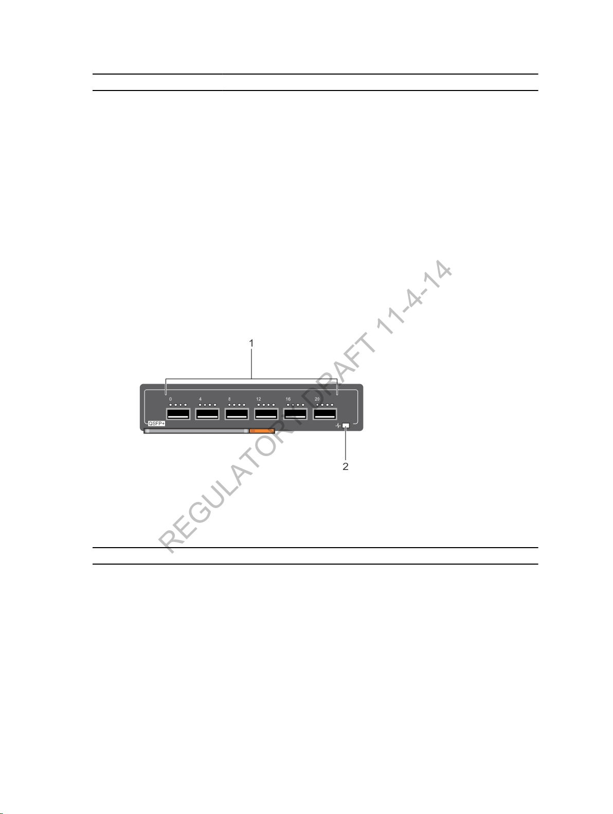
Figure 27. 40G QSFP+ Port LEDs
• Off
• Solid green
•
• Solid amber
• Off
• Flashing green
• No data link
• Link is up and operating at maximum port
speed; if auto-negotiated, port is
operating at 1G.
• Link is up and operating at lower speed; if
auto-negotiated, port is operating at
10/100M.
• No data link activity
• Link is up and transmitting/receiving data.
1. 4x10G Link/Activity Port LEDs above each 40G
QSFP+ port
Table 3. 40GE QSFP+ Port LEDs
LED LED Color Description
40GE Port link/activity
LED
36
• Off
• Solid green
• Flashing green
• Solid amber
• Flashing amber
• Flashing amber (1
second on, 1
second off
2. Module Status LED
• No link or interface is disabled.
• 40G link is up and 40GE QSFP+ interface is enabled.
• 40GE port is transmitting/receiving data at
maximum 40G speed.
• 40G link is up but operating at lower speed (less
than 40G).
• 40GE port is transmitting/receiving data at a lower
speed (less than 40G).
Installing the Hardware
Page 37
LED LED Color Description
REGULATORY DRAFT 11-4-14
• Port beacon used to locate port
4x10GE Port link/
activity LED
Module status LED
• Off
• Solid amber
• Flashing amber
• Flashing amber (1
second on, 1
second off
• Off
• Solid green
• Flashing blue
• Flashing amber
• No link or interface is disabled.
• 10G link is up and operating at 10G speed.
• 4x10GE port is transmitting/receiving data at 10G
speed.
• Port beacon used to locate port
• No power
• Normal operation
• Beacon LED is being used to locate the module.
• Error condition or reload in progress
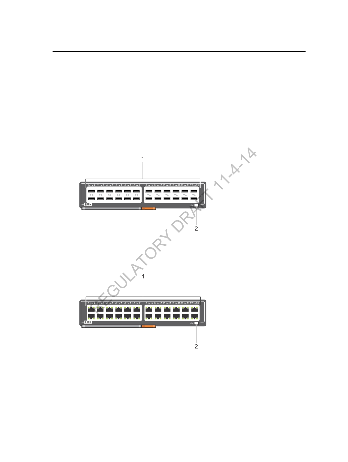
Figure 28. 1/10G SFP+ Port LEDs
1. 24 1/10G SFP+ ports with locator LEDs (up and down arrows)
2. Module Status LED
Figure 29. 1/10G RJ-45 Port LEDs
1. 24 1/10G SFP+ ports with Link/Activity Status LEDs (up and down arrows indicate port numbers)
2. Module Status LED
Installing the Hardware
37
Page 38
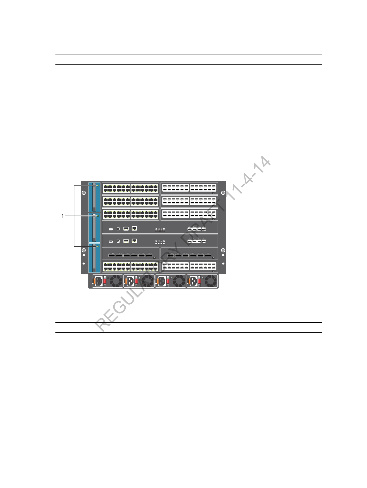
Table 4. 1/10G SFP+ and 1/10G RJ-45 Port LEDs
REGULATORY DRAFT 11-4-14
LED LED Color Description
Link/Activity Status LED
• Off
• Solid green
• Flashing green
• Solid amber
• Flashing amber
• Flashing amber (1
second on, 1
second off
• No link
• 10G link is up and 10GE interface is enabled.
• 10G port is transmitting/receiving data.
• 1G link is up and 1GE interface is enabled.
• 1G port is transmitting/receiving data.
• Port beacon used to locate port
Module status LED
Figure 30. FAN LED
• Off
• Solid green
• Flashing blue
• Flashing amber
• No power
• Normal operation
• Beacon LED is being used to locate the module.
• Error condition or reload in progress
Table 5. Fan LED
LED LED Color Description
Fan status
38
• Solid blue
• Flashing blue
• Solid amber
• Off
• Normal operation; fan is receiving power.
• Beacon LED is being used to locate the fan
tray.
• Error condition or reload in progress
• Fan is not receiving power.
Installing the Hardware
Page 39
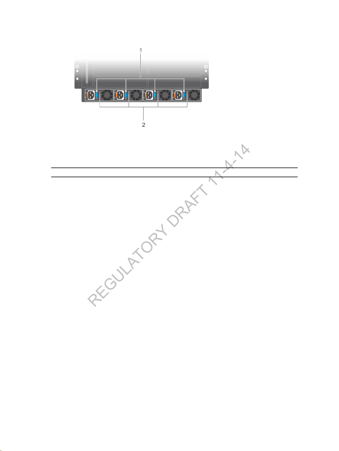
Figure 31. PSU LEDs
REGULATORY DRAFT 11-4-14
1. PSU LED: DC output (on handle) 2. PSU LED: AC input power
Table 6. PSU LEDs
LED LED Color Description
PSU: DC output
• Solid green
• Solid amber
• Flashing amber
• Normal DC power output
• Alarm: PSU is not operational due
to fault condition
• Alarm: Overheating condition
PSU: AC input power
• Solid green
• Flashing green
• Off
• Normal operation; PSU is receiving
power.
• Alarm: PSU is receiving power, but
DC output is disabled.
• PSU is receiving power outside of
the supported range and is not
operational.
Installing the Hardware
39
Page 40

4
REGULATORY DRAFT 11-4-14
Configuring the Software
After you install the switch in a rack and power it up, perform the initial software configuration using the
command-line interface or Bare Metal Provisioning (BMP) to connect to the network. This chapter
describes how to configure the C9010 using the CLI.
BMP allows the C9010 to receive a Dell Networking OS image and startup configuration file with initial
software settings, including IP address, from a DHCP server. For more information about BMP, refer to
the Dell Networking Open Automation Guide: Configuration and Command Line Reference. To connect
a BMP-enabled switch to a network so that it can search the network for a DHCP server, see Connecting
the Switch to the Network.
To use the CLI to configure the system, follow these steps:
1. Connect a console terminal to the RJ-45/RS-232 or USB-B console port to enter the initial
configuration information.
2. Configure the enable password.
3. Configure a host name.
4. Configure layer 2 (data Link) mode.
5. Configure the management port IP address.
6. Configure a management route.
7. Configure a username and password.
8. Create a port-based VLAN.
9. Assign interfaces to a VLAN.
10. Assign an IP address to a VLAN.
11. Connect the system to the network.
For complete information about how to configure and monitor your system, refer to the Dell Networking
Configuration Guide for the C9000 Series. For the latest documentation and firmware updates, refer to
the Dell Support website at http://www.dell.com/support
C9010 Console Ports
To perform initial software configuration, you must connect an external console to the C9010 switch.
The C9010 RPM provides two types of console interfaces: RJ45 and USB-B.
The RJ45 and USB-B console ports are located on the left side of the RPM as you face the chassis.
40
Configuring the Software
Page 41
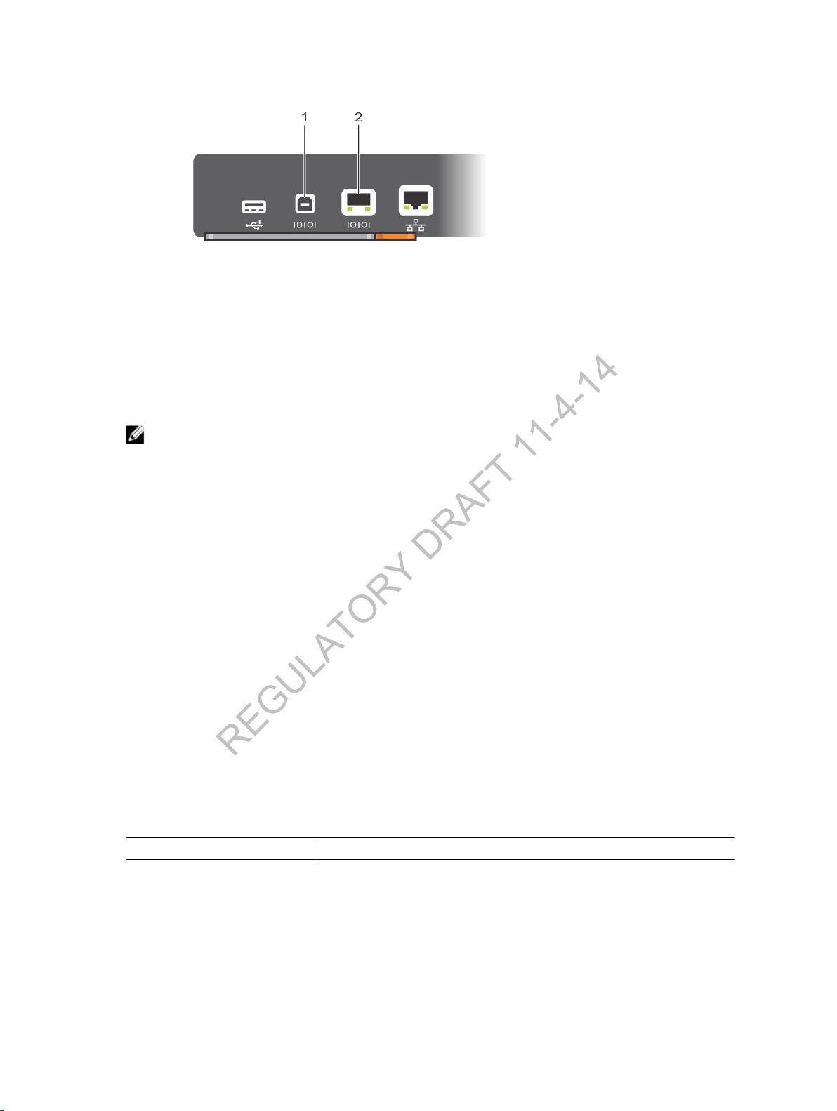
Figure 32. Console Ports on Route Processor Module
REGULATORY DRAFT 11-4-14
1. USB-B console port 2. RJ45 console port
Setting RJ45 Console Access
The RJ45 console port is an asynchronous serial port. If you connect a console to this port, it must
support asynchronous transmission.
: Before connecting a console, be sure that a terminal emulation program is already installed
NOTE
on your PC console.
1. Install an RJ-45 copper cable into the console port. To connect the C9010 console port to a
terminal server, use a rollover cable.
2. Connect the other end of the cable to the DTE terminal server.
3. Set your terminal or terminal emulation mode to VT100 with the following settings:
• 9600 baud rate
• No parity
• 8 data bits
• 1 stop bit
• Window Terminal Emulator option set to NO
• 24 lines x 80 characters
• No flow control
RJ45 Cable and Adapter Pin Assignments
To configure and monitor your system, you can connect to a terminal port, PC serial port, or a terminal
server by using the RJ45 console port on the RPM. An RJ-45 Ethernet cable is required to connect to the
Ethernet port.
The following table describes the pinouts for the RJ-45 console port.
Table 7. Pin Assignments for the RJ-45 Console Port
Pin Serial Input/Output
1 NC (unused) -
2 DTR Output
3 TxD Output
Configuring the Software
41
Page 42

Pin Serial Input/Output
REGULATORY DRAFT 11-4-14
4 GND -
5 GND -
6 RxD Input
7 DSR Input
8 NC (unused) -
RJ45 Console Access with a DB-9 Adapter
You can connect to the console through the RJ45 console port using an RJ-45 to RJ-45 rollover cable
and an RJ-45 to DB-9 female DTE adapter (labeled TERMINAL) to a terminal server (for example, a PC).
Table 8. Pin Assignments Between the Console and a DTE Terminal Server
Console Port RJ-45 to RJ-45
Rollover Cable
Signal RJ-45 Pinout RJ-45 Pinout DB-9 Pin DB-9 Pin
RTS 1 8 8 CTS
DTR 2 7 6 DSR
TxD 3 6 2 RxD
GND 4 5 5 GND
GND 5 4 5 GND
RxD 6 3 3 TxD
DSR 7 2 4 DTR
CTS 8 1 7 RTS
RJ-45 to RJ-45
Rollover Cable
RJ-45 to DB-9 Terminal Server
Device
RJ45 Console Access with a DB-25 Adapter
You can connect to the console port through the RJ45 console port using an RJ-45 to RJ-45 rollover
cable and an RJ-45 to a DB-25 female DTE adapter.
Table 9. Pin Assignments Between the Console and a DTE Terminal Server
Console Port RJ-45 to RJ-45
Rollover Cable
Signal RJ-45 Pinout RJ-45 Pinout DB-25 Pinout Signal
RJ-45 to RJ-45
Rollover Cable
RJ-45 to DB-25
Modem Adapter
Terminal Server
Device
RTS 1 8 5 CTS
DTR 2 7 6 DSR
TxD 3 6 3 RxD
GND 4 5 7 GND
GND 5 4 7 GND
RxD 6 3 2 TxD
DSR 7 2 20 DTR
42
Configuring the Software
Page 43

Console Port RJ-45 to RJ-45
REGULATORY DRAFT 11-4-14
Rollover Cable
Signal RJ-45 Pinout RJ-45 Pinout DB-25 Pinout Signal
CTS 8 1 - RTS
RJ-45 to RJ-45
Rollover Cable
RJ-45 to DB-25
Modem Adapter
Terminal Server
Device
Setting USB-B Console Access
For the location fo the USB-B console port, refer to C9010 Console Ports.
The terminal settings are the same for the USB-B and RJ-45 console port:
• 9600 baud rate
• No parity
• 8 data bits
• 1 stop bit
• No flow control
When you connect a console device to the USB-B port, it becomes the primary connection and it sends
all messages to the USB-B drive.
1. Power on the PC.
2. Install the necessary USB device drivers (you will need an Internet connection). For assistance,
contact Dell Networking Technical Support.
3. Connect the USB-A end of cable into an available USB port on the PC.
4. Connect the USB-B end of cable into the USB-B console port on the system.
5. Power on the system.
6. Open your terminal software emulation program to access the system.
7. Set the terminal connection settings:
• 9600 baud rate
• No parity
• 8 data bits
• 1 stop bit
• No flow control
: Only one of the console ports can be active at a time; a USB console takes priority over an
NOTE
RJ-45 console by default. When a USB host (PC) is plugged into the USB-B console port, the C9010
hardware automatically switches over to use the USB console. When you remove the USB cable or
the PC deactivates the USB connection, the C9010 automatically switches to the RJ-45 console
interface.
Initial Software Configuration
After you connect a console terminal, the CLI prompt appears (Dell>_
default user name and password to log in.
Although a version of the Dell Networking operating system is pre-loaded on the chassis, the system is
not configured when you power up for the first time (except for the default host name, which is
).This section describes how to configure the system using the CLI.
Dell
To set up the switch, you must assign an IP address and other configuration information necessary for
the switch to communicate with the local routers and the Internet. The minimal configuration provided in
Configuring the Software
). It is not necessary to enter a
43
Page 44

this guide does not cover most of the features; it simply allows you to perform other configuration tasks
REGULATORY DRAFT 11-4-14
using a Telnet connection from your management network. To configure other features and interfaces,
refer to the Dell Networking C9000 Series Configuration Guide.
To perform the initial software configuration, you will need the following information from your network
administrator:
• Switch IP address
• Subnet mask (IP netmask)
• Default gateway (router)
• Enable secret password
• Enable password
• Telnet password
Command Modes
After you install the hardware and the boot process completes, the console monitor displays the CLI
prompt for the EXEC command mode.
You must move linearly through the command modes; for example:
Prompt CLI Command Mode
Dell>
Dell#
Dell(conf)#
Dell(conf-b)#
Enter the
directly to EXEC Privilege mode.
exit command to move back up one command mode level. Enter the end command to move
EXEC
enable to access EXEC Privilege mode.
Enter
EXEC Privilege
Enter
configure to access CONFIGURATION mode.
CONFIGURATION
Enter configure terminal batch to access CONFIGURATION BATCH mode.
CONFIGURATION BATCH
Configuring the Enable Password
To access EXEC Privilege mode, you must use the
Configure a password as a basic security measure. When using a console connection, EXEC Privilege
mode is unrestricted by default; it cannot be reached by a VTY connection if you do not configure a
password. There are two types of enable passwords:
• enable password stores the password in the running/startup configuration using a DES encryption
method.
• enable secret stores the password in the running/startup configuration by using a stronger, MD5
encryption method.
enable command.
Dell Networking recommends using the enable secret password.
44
Configuring the Software
Page 45

• Create a password to access EXEC Privilege mode.
REGULATORY DRAFT 11-4-14
CONFIGURATION mode
enable [password | secret] [level level] [encryption-type] password
level is the privilege level and is not required. The default is 15.
encryption-type specifies how you are inputting the password and is not required. The default is 0.
– 0 is for inputting the password in clear text.
– 7 is for inputting a password that is already encrypted using a DES hash. Obtain the encrypted
password from the configuration file of another Dell Networking system.
– 5 is for inputting a password that is already encrypted using an MD5 hash. Obtain the encrypted
password from the configuration file of another Dell Networking system.
Configuring a Host Name
The host name appears in the prompt. The default host name is Dell. Host names must start with a
letter, end with a letter or digit, and have characters, letters, digits, and hyphens in the string.
• Create a new host name.
CONFIGURATION mode
hostname name
Port Numbering
On the C9010, port numbers are written above ports on a line card. All line cards are hot-swappable.
For an example of port numbering on a 40G QSFP+, 1/10G SFP+, and 1/10G RJ-45 line card, see
Checking LED Status.
On the 6-Port 40G QSFP+ line card, ports operate by default in 40GbE mode. If you use a breakout
cable, each port can operate in 4x10GbE mode. 40GbE ports are numbered in multiples of four, starting
with zero; for example, 0, 4, 8, 12, and so on. When a breakout cable is installed, the resulting four 10GbE
ports are numbered with the remaining numbers. For example, 40GbE port 0 contains 10GbE ports 0, 1,
2, and 3; 40GbE port 4 contains 10GbE ports 4, 5, 6, and 7.
Configure Layer 2 (Data Link) Mode
To enable Layer 2 data transmissions on a specified interface, use the switchport command in
INTERFACE mode.
You cannot configure switching or Layer 2 protocols, such as the Spanning Tree Protocol (STP), on an
interface unless the interface has been set to Layer 2 mode.
1. Enable the interface.
INTERFACE mode
no shutdown
2. Place the interface in Layer 2 (switching) mode.
INTERFACE mode
Configuring the Software
45
Page 46

switchport
REGULATORY DRAFT 11-4-14
To view the interfaces in Layer 2 mode, enter the show interfaces switchport command in EXEC
mode.
Accessing the System Remotely
You can configure the switch so that it can be accessed remotely over a Telnet connection.
The C9010 system has a dedicated management port and a management routing table that is separate
from the IP routing table. To configure the system for Telnet access:
1. Configure an IP address for the management port.
2. Configure a management route with a default gateway.
3. Configure a user name and password.
Configuring the Management Port IP Address
To access the system remotely, you must assign IP addresses to the management ports.
NOTE
: Assign different IP addresses to each RPM management port.
1. Enter INTERFACE mode for the Management port.
CONFIGURATION mode
interface ManagementEthernet 0/0
2. Assign an IPv4 or IPv6 address to the interface.
INTERFACE mode
ip address {ipv4-address | ipv6- address}/
• ip-addressis an address in dotted-decimal format (A.B.C.D).
• maskis a subnet mask in /prefix-length format (/ xx).
3. Enable the interface.
INTERFACE mode
no shutdown
mask
Configuring a Management Route
Define a path from the system to the network from which you are accessing the system remotely.
Management routes are separate from IP routes and are only used to manage the system through the
management port.
• Configure an IPv4 or IPv6 management route to the network from which you are accessing the
system.
CONFIGURATION mode
management route {ipv4-address |
– ip-address is the network address in dotted-decimal format (A.B.C.D).
– mask is a subnet mask in /prefix-length format (/ xx).
– gateway is the next hop for network traffic originating from the management port.
ipv6-address}/mask gateway
46
Configuring the Software
Page 47

Configuring a Username and Password
REGULATORY DRAFT 11-4-14
To access the system remotely, configure a system user name and password.
• Configure a user name and password to access the system remotely.
CONFIGURATION mode
username username password [encryption-type] password
An encryption-type parameter is not necessary because it is 0 by default, which allows you to
enter the password in clear text.
Splitting QSFP+ Ports into SFP+ Ports
On a 6-Port 40G QSFP+ line card, you can split a single 40GbE QSFP+ port into four 10GbE SFP+ ports
using one of the supported breakout cables. For a list of supported optics, contact your Dell Networking
representative or reseller.
A 40G (quad) port must be in a default configuration before you can split it into four 10G SFP+ ports.
When you split the port, the 40G interface configuration is lost in the running configuration. The CLI
split-port change immediately takes effect due to the dynamic fan-out feature; it is not necessary to
reload the system. Be sure that you also remove the 40G port from other L2/L3 feature configurations.
• Configure the switch to recognize the port mode change.
CONFIGURATION mode
linecard number port
– linecard number
range is 0 to 11; the port range is 0 to 20.
– portmode quad configures a 40G port to operate in 4x10G mode.
For example:
Dell# linecard 0 port 5 portmode quad
number portmode quad
port number
specifies the line card and 40G port to be split. The line-card
Creating a VLAN
The default VLAN is VLAN 1 (by default) and is stored in the startup configuration.
You can configure a different VLAN number as the default VLAN. You cannot delete or disable the default
VLAN 1; you cannot assign it an IP address. Only untagged interfaces can belong to the default VLAN.
When you configure an interface, the switchport command automatically places it in the default VLAN
as an untagged interface. All switchport interfaces must belong to at least one VLAN. To remove a
switchport from the default VLAN, configure it as tagged or untagged member of another VLAN or
remove the switchport configuration.
• Create a VLAN
CONFIGURATION mode
interface vlan vlan-id
• Display all VLANs.
EXEC Privilege mode
Configuring the Software
47
Page 48

show vlan vlan-id
REGULATORY DRAFT 11-4-14
Assigning Interfaces to a VLAN
You can only assign interfaces in Layer 2 mode to a VLAN using the tagged and untagged commands.
To place an interface in Layer 2 mode, use the switchport command. A port can be an untagged
member of a single VLAN or a tagged member of multiple VLANs. When you place an interface in Layer 2
mode using the
placed in the default VLAN.
• Tagged ports append an 802.1Q tag to frames on egress and accept only tagged frames on ingress
(untagged frames are dropped). You must connect tagged ports to VLAN-aware devices.
• Untagged ports do not append an 802.1Q VLAN tag to frames on egress and do not accept tagged
frames on ingress (tagged frames are dropped). You must connect untagged ports to VLAN-unaware
devices. To remove an untagged from the default VLAN, remove the switchport configuration.
To assign an interface to a VLAN:
1. Enter INTERFACE VLAN mode of the VLAN to which you want to assign the interface.
CONFIGURATION mode
interface vlan vlan-id
2. Assign a switchport interface to a VLAN as a tagged or untagged member.
VLAN INTERFACE mode
switchport command, the interface is automatically configured as untagged and
[tagged | untagged] slot/
3. Display all switchport interfaces and the VLANs to which they belong.
EXEC Privilege mode
show vlan
To view only the interfaces that are in Layer 2 mode, enter the show interfaces switchport
command in EXEC Privilege mode or EXEC mode.
To move a port interface to another VLAN, add it to the desired VLAN as either a tagged or untagged
member.
port
Assigning an IP Address to a VLAN
Because VLANs are a Layer 2 feature, you must assign an IP address to a VLAN interface in order for
physical interfaces on different VLANs to communicate and route traffic.
You cannot assign an IP address to the default VLAN, which, is VLAN 1.
shutdown command in INTERFACE mode does not affect Layer 2 traffic on a VLAN interface.
The
• Configure an IP address and mask on a VLAN interface.
VLAN INTERFACE mode
ip address ip-address mask [secondary]
Connecting the Switch to the Network
After you complete the hardware installation and CLI-based software configuration for a C9010 switch,
you can connect to a network through the 10/100/1000Base-T RJ-45 management port. If you are using
48
Configuring the Software
Page 49
BMP to configure the switch, you can connect to the network to search for a DHCP server after you
REGULATORY DRAFT 11-4-14
complete the C9010 hardware installation.
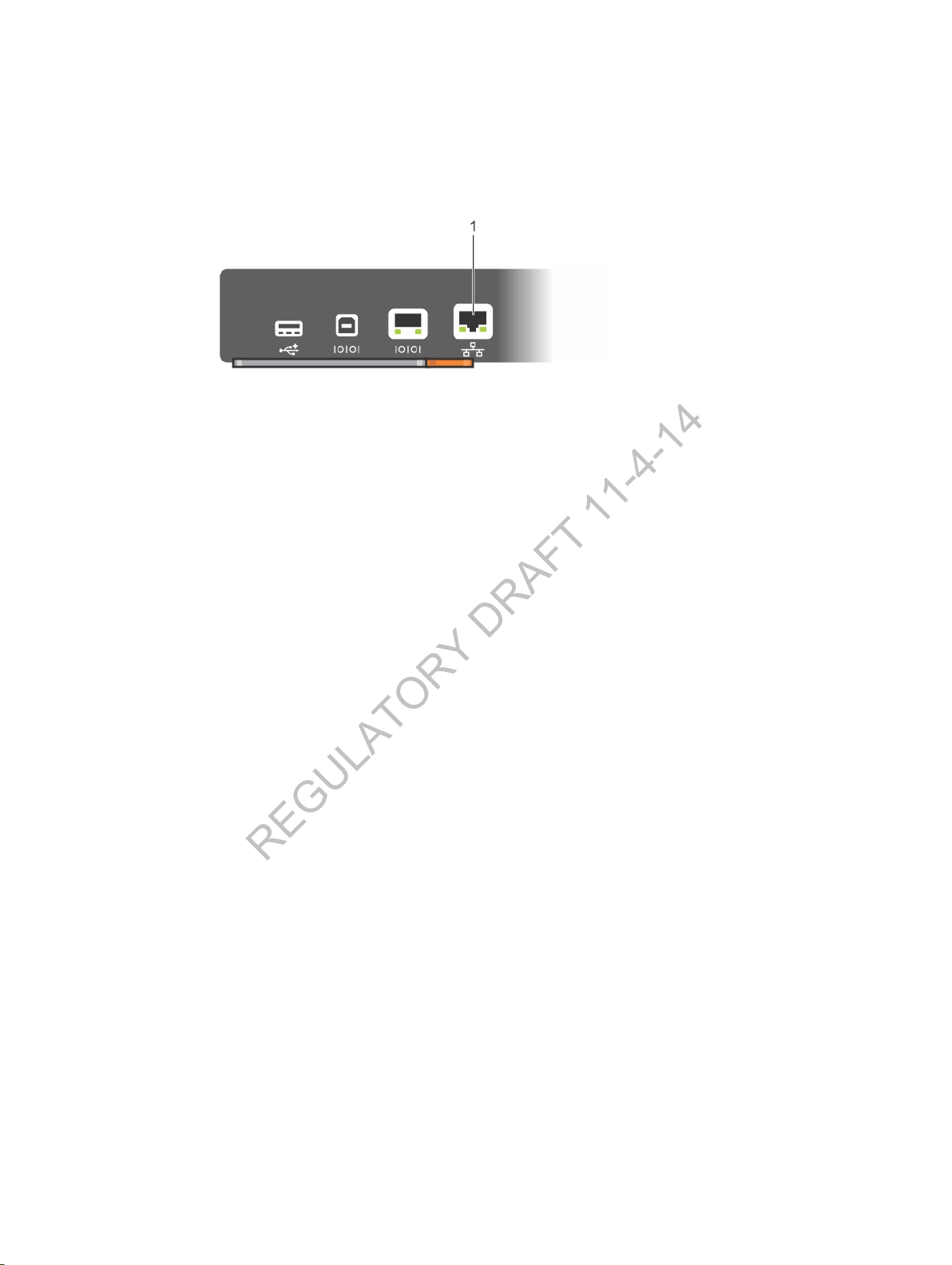
The RJ-45 network management port is located on the left side of the RPM as you face the chassis. Use a
supported RJ-45 cable for a network connection.
Figure 33. RJ-45 Network Management Port
1. RJ-45 network management port
Configuring the Software
49
Page 50

5
REGULATORY DRAFT 11-4-14
Dell Networking Support
The Dell Networking Support site provides a range of documents and tools to assist you with effectively
using Dell Networking equipment and mitigating the impact of network outages. Through the support
site you can obtain technical information regarding Dell Networking products, access software upgrades
and patches, download available management software, and manage your open cases. The Dell
Networking support site provides integrated, secure access to these services.
To access the Dell Networking Support site, go to https://www.dell.com/support/. To obtain productspecific information, enter the 7-character service tag or 11-digit express service code of your C9010
switch and click Submit.
To view the service tag or express service code on a C9010, pull out the tag (item 1 in Figure 34) located
on the shelf in RPM slot 0 or enter the
show chassis command from the command-line interface.
To receive additional kinds of technical support, go to
category/Contact-Information/Technical-Support.
https://www.dell.com/support/contents/us/en/04/
50
Dell Networking Support
Page 51
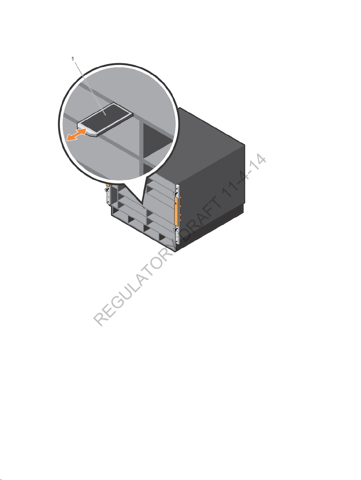
Figure 34. C9010 Service Tag
REGULATORY DRAFT 11-4-14
Dell Networking Support
51
Page 52

Technical Specifications
REGULATORY DRAFT 11-4-14
The following chapter describes specifications for the C1048P port extender.
Table 10. Chassis Physical Design
Parameter Specifications
Height 13.9 inches (35.26 cm)
Width 17.4 inches (44.20 cm)
Depth 18.0 inches (45.70 cm)
Chassis weight
Table 11. Environmental Parameters
Parameter Specifications
Operational temperature -23° to 113°F (-5°C to 45°C) (storage temperature)
Non-operational temperature -40° to 158°F (-40°C to 70°C)
Relative humidity 5 to 95% (non-condensing)
55 lbs (24.95 kg) with factory installed components
152.27 lbs (69.07 kg) fully loaded
6
Table 12. AC Power Requirements
Parameter Specifications
Nominal input voltage 100/120 VAC 50/60Hz and 200/240VAC 50/60Hz
Maximum AC power-supply input
current (based on 1450 W output
for 100/120 V and 2900 W output
200/240 V lines)
Maximum system power input (for
system configuration with four
power supply units)
Maximum system power
consumption
Maximum system thermal output
at 100/120 V
52
16 A @ 100 V per AC power supply
14 A @ 120 VAC per AC power supply
16 A @ 200 VAC per AC power supply
14 A @ 240 VAC per AC power supply
6,400 KVA @ 100/120 V
12,800 KVA @ 200/240 V
5,349 W @ 100/120 V
11,055 W @ 200/240 V
18,247 BTU/hour
Technical Specifications
Page 53

Parameter Specifications
REGULATORY DRAFT 11-4-14
Maximum system thermal output
at 200/240 V
37,714 BTU/hour
Technical Specifications
53
 Loading...