

Page 1
RC GROUP
Indice - Index
MP2000 - Controllo a microprocessore per condizionatori
MP2000 - Air conditioners microprocessor control
RC GROUP
Page 2

Page 3

MP2000 sistema di controllo a microprocessore per condizionatori
MP2000 air conditioners microprocessor control system
RC GROUP - 149_ItEn.0102
3
Page 4

MP2000 AIR CONDITIONERS
Sistema di controllo a microprocessore per condizionatori d'aria •
Air conditioners microprocessor control system
GENERALITA' .................................................................................................6 ...................................................................................................
CONFIGURAZIONE HARDWARE MP2000.................................................... 7 ......................................................
Schede BOARD "A" e "B" ......................................................................... 8 ........................................................................
Terminale ................................................................................................. 10 ...................................................................................................
Scheda "ADDR" ....................................................................................... 11 ............................................................................................
Scheda "ADDR+CK" ................................................................................ 12 .....................................................................................
Scheda "T" ............................................................................................... 13 ....................................................................................................
Porta seriale RS485 ................................................................................ 14 .............................................................................
Scheda umidificatore ............................................................................... 15 ........................................................................................
Terminale Remoto "T" .............................................................................. 16 ...............................................................................
POSSIBILI CONFIGURAZIONI DEL SISTEMA MP2000 .............................. 17 ......................................................
Configurazione con BOARD "A" e Terminale a bordo macchina ............. 17 ..............................
Versione con Terminale Remoto "T" ........................................................ 17 ...........................................................
Configurazione con BOARD "A" e "B" e Terminale a bordo macchina .... 19 .................
Versione con Terminale Remoto "T" ....................................................... 19 ...........................................................
CONNESSIONI ELETTRICHE ....................................................................... 21 ..........................................................................
Alimentazione elettrica............................................................................. 21 ........................................................................................
Connessione tra Terminale e scheda BOARD "A" ................................... 21 ......................................................
Connessione tra BOARD "A" e "B" .......................................................... 22 .................................
Connessione tra BOARD "A" e Terminale Remoto "T" ........................... 22 ...................
Connessione seriale RS485 .................................................................... 24 .........................................................................
Connessione sistema di umidificazione ................................................... 26 ...........................................................
Connessione rete LAN ............................................................................ 27 .......................................................................................
Connessione sistema di compensazione set point temperatura ............. 28 .......................
INSERIMENTO DELLA EPROM .................................................................... 29 ..................................................................
FUNZIONI DELLA TASTIERA E PROGRAMMAZIONE ................................ 30 ..........................................
Funzioni della tastiera ..............................................................................30 ..................................................................................
Ritorno alla maschera principale ............................................................. 31 ............................................................................
Partenza random dell'unità ...................................................................... 32 .....................................................................
Funzionamento dell'unità (Ventilatore principale) .................................... 32 ....................................................................
Funzione CHRONO (a richiesta) ............................................................. 32 ..............................................................
Indicazione temperatura uscita aria ......................................................... 34 ..........................................................
Funzione Limit Thermostat ...................................................................... 34 ........................................................................
Inversione senso avviamento compressori ............................................. 35 ..............................................
Presenza allarmi ...................................................................................... 36 .....................................................................................
Visualizzazione ultimi 10 allarmi .............................................................. 36 ....................................................................
Contaore e allarme manutenzione .......................................................... 36 .........................................................
Reset allarmi ............................................................................................37 ..............................................................................................
Comandi manuali ..................................................................................... 37 ...................................................................................
Set point .................................................................................................. 40 ..................................................................................................
Program sets ........................................................................................... 40 ...........................................................................................
Set manufacturer ..................................................................................... 40 .....................................................................................
Memory reset ...........................................................................................41 ..........................................................................................
Calibrazione sonde .................................................................................. 41 ..................................................................................
RETE LOCALE LAN (Local Area Network) ................................................. 42 ........................................................
CONFIGURAZIONE HARDWARE RETE LAN ........................................ 43 .................................
Verifica architettura hardware .................................................................. 43 ....................................................................
Impostazione dei codici di indirizzamento ............................................... 43 ...............................................................................
Codici di indirizzamento ........................................................................... 44 ..........................................................................................
CONFIGURAZIONE SOFTWARE RETE LAN ........................................ 45 ..................................
Verifica automatica della configurazione hardware ................................. 45 ......................................
Configurazione software manuale ........................................................... 46 ................................................................
Elenco maschere ..................................................................................... 48 .................................................................................................
Definizione del numero di unità presenti nella rete .................................. 48 .......................
Condivisione Terminali ............................................................................. 49 ......................................................................................
Funzione CHANGE OVER ...................................................................... 50 ........................................................................
IL SISTEMA DI REGOLAZIONE .................................................................... 53 .................................................
Simbologia utilizzata nei grafici ................................................................ 53 .........................................................................
Gli stadi ON/OFF ..................................................................................... 54 ................................................................................
I segnali proporzionali di temperatura ..................................................... 54 ......................................................
I segnali proporzionali di pressione ......................................................... 55 .............................................................
Le valvole a 3 punti (Floating) ................................................................. 55 ....................................................................................
La funzione LIMIT per la deumidificazione .............................................. 57 ..................................................
Gli allarmi termoigrometrici ...................................................................... 58 ...............................................................
IDENTIFICAZIONE EPROM ........................................................................... 59 .............................................................................
EPROM CZX.... ............................................................................................... 61 ..................................................................................................
Software per condizionatori
Schema INGRESSI/USCITE BOARD "A" ............................................... 62 .................................................
Schema INGRESSI/USCITE BOARD "B" ............................................... 64 .................................................
ELENCO SET .......................................................................................... 66 .................................................................................................
Set point .................................................................................................. 66 ..................................................................................................
Procedura manuale ................................................................................. 66 ...................................................................................
Configurazione unità ................................................................................ 67 ....................................................................................
Parametri generali ................................................................................... 68 ................................................................................
Parametri temporizzazioni ....................................................................... 70 ..................................................................................
Inizializzazione unità ................................................................................ 70 ......................................................................................
Set programmabili.................................................................................... 70 .............................................................................................
ELENCO STATUS ................................................................................... 72 ..........................................................................................
Calibrazione sonde .................................................................................. 74 ....................................................................................
SOMMARIO
Configuration with BOARD "A" and Terminal on unit
Configuration with BOARD "A" and "B" and Terminal on unit
Connection between BOARD "A" and BOARD "B"
Connection between BOARD "A" and "T" Remote Terminal
Temperature set point compensation system connection
LAN NETWORK HARDWARE CONFIGURATION
LAN NETWORK SOFTWARE CONFIGURATION
Definition of the number of units presents in the network
4
SUMMARY
MP2000 HARDWARE CONFIGURATION
BOARD "A" and "B" cards
"ADDR" card
"ADDR+CK" card
RS485 serial port card
Humidifier card
"T" Remote Terminal
MP2000 POSSIBLE CONFIGURATIONS
Version with "T" Remote Terminal
Version with "T" Remote Terminal
ELECTRIC CONNECTIONS
Electric feeding
Terminal and BOARD "A" connection
Serial connection RS485
Humidification system connection
LAN connection
INSTALLATION OF THE EPROM
KEYBOARD FUNCTION AND PROGRAMMING
Keyboard functions
Back to the main menu
Random starting of the unit
Unit switch on (main fan on)
CHRONO function (on request)
Air delivery temperature indication
Limit Thermostat function
Compressors' starting sequence inversion
Alarms presence
Last 10 alarms visualization
Hourmeter and maintenance alarm
Manual procedure
Program sets
Set manufacturer
Memory reset
Sensors calibration
LAN NETWORK (Local Area Network)
Verify hardware architecture
Address code setting
Address code
Automatic check of the hardware configuration
Manual software configuration
Terminal sharing
CHANGE OVER function
PRINCIPLES OF THE CONTROL SYSTEM
Symbols used on graphs
The ON/OFF stages
The temperature proportional signals
The pressure proportional signal
The floating valve
The LIMIT function for dehumidification
The thermohygrometric alarms
EPROM IDENTIFICATION
Software for air conditioners
BOARD "A" INLETS/OUTLETS diagram
BOARD "B" INLETS/OUTLETS diagram
Manual procedure
Unit configuration
General parameters
Timing parameters
Unit initialization
Program set
STATUS LIST
Probes calibration
RC GROUP - 149_ItEn.0102
FOREWORD
Terminal
"T" card
Alarm reset
Set point
Masks list
EPROM CZX
SET LIST
Set point
Page 5

MP2000 AIR CONDITIONERS
Sistema di controllo a microprocessore per condizionatori d'aria •
Air conditioners microprocessor control system
ELENCO SET MANUALI ......................................................................... 75 .................................................................................
ELENCO MEMO ...................................................................................... 75 .............................................................................................
Logica di raffreddamento con unità ad espansione diretta ...................... 76 ..................................................
Logica di raffreddamento con unità ad espansione diretta+Free-cooling 78 ............................
Funzione Free-cooling (sistema FC) ....................................................... 80 ..........................................................
Logica di funzionamento sistema FC ....................................................... 80 .........................................................................
Logica di raffreddamento con unità ad acqua refrigerata ........................ 82 .........................................................
Logica di riscaldamento con resistenze elettriche ................................... 84 ...........................................................
Logica di riscaldamento con sistema ad acqua calda ............................. 86 ........................................................
Logica di controllo umidità ....................................................................... 88 ..............................................................................
Logica di controllo sistema di deumidificazione ....................................... 89 .....................................................
Logica di controllo della pressione di condensazione ............................. 90 ..........................................................
Logica di compensazione set point temperatura ..................................... 92 ..............................................
EPROM CPX .... ............................................................................................. 93 ..................................................................................................
Software per condizionatori a pompa di calore e Roof Top
Schema INGRESSI/USCITE BOARD "A" ............................................... 94 .................................................
Schema INGRESSI/USCITE BOARD "B" ............................................... 96 .................................................
ELENCO SET .......................................................................................... 98 .................................................................................................
Set point .................................................................................................. 98 ..................................................................................................
Procedura manuale ................................................................................. 98 ...................................................................................
Configurazione unità ................................................................................ 99 ....................................................................................
Parametri generali .................................................................................. 100 ...............................................................................
Parametri temporizzazioni ...................................................................... 102 .................................................................................
Inizializzazione unità ............................................................................... 102 .....................................................................................
Set programmabili ................................................................................... 102 ............................................................................................
ELENCO STATUS .................................................................................. 104 .........................................................................................
Calibrazione sonde ................................................................................. 106 ....................................................................................
ELENCO SET MANUALI ........................................................................ 107 ................................................................................
ELENCO MEMO ..................................................................................... 107 ............................................................................................
Logica di raffreddamento con unità ad espansione diretta ..................... 108 .................................................
Logica di comando apertura serranda Free-Cooling aria esterna .......... 110 .............
Logica di abilitazione e disabilitazione Free-Cooling .............................. 111 ....................................................
Logica di riscaldamento .......................................................................... 112 ...........................................................................................
Logica di controllo umidità ...................................................................... 114 .............................................................................
Logica di controllo della pressione di condensazione ............................ 116 .........................................................
Logica di compensazione set point temperatura .................................... 118 .............................................
Logica di sbrinamento per unità a pompa di calore ................................ 119 ...................................................
ELENCO E DESCRIZIONE ALLARMI .......................................................... 121 ............................................................
Logica di gestione relé di remotizzazione allarmi ................................... 122 ................................
Elenco allarmi ......................................................................................... 123 ...............................................................................................
Descrizione allarmi ................................................................................. 124 ....................................................................................
COMPONENTI DEL SISTEMA MP2000.... ................................................... 135 .................................................
Sonda di temperatura NTC ..................................................................... 136 ........................................................................
Sonda di temperatura ed umidità ........................................................... 137 ..........................................................
Sensore di pressione gas refrigerante .................................................... 138 ............................................................
TA20/4 - Trasformatore amperometrico per corrente umidificatore ........ 139 .....................
TV600 - Trasformatore voltmetrico per tensione di linea ........................ 140 .....................................
TA100 - Trasformatore amperometrico per corrente di linea .................. 141 ................................
TA500 - Trasformatore amperometrico per corrente di linea .................. 142 ................................
RC 275 - Convertitore di tensione .......................................................... 143 ....................................................................
RC 420 - Relè segnalazione presenza acqua + sonda .......................... 144 ...............................................
LV2D - Relè segnalazione presenza acqua + sonda.............................. 145 ...................................................
P11 - Regolatore di velocità per motori monofase .................................. 146 .......................
P12 - Regolatore di velocità per motori monofase ................................. 147 ......................
RIV 1200 - Regolatore di velocità per motori monofase ......................... 148 ..............
DVR - Regolatore di velocità per motori trifase ...................................... 150 ......................
FCS - Regolatore di velocità per motori trifase ....................................... 152 .......................
RC 411A - Convertitore di segnale ad 1 stadio ....................................... 154 ........................................................
RC 470 - Convertitore di segnale a 3 stadi ............................................. 155 ........................................................
RC 460 - Relè di protezione minima corrente (1,5A) .............................. 156 ................................
RC 465 - Relè di protezione minima corrente (10A) ............................... 157 .................................
RC 480a - Dispositivo per unità terminali Flexibox ................................. 158 ...........................................
RC 480b - Dispositivo per unità terminali Flexibox ................................. 159 ...........................................
RCE84.21 - Regolatore ambiente per Flexibox ...................................... 160 ...............................................
RC 285 - Box diodi per segnali 0÷10V ................................................... 162 .................................................
Pressostato differenziale aria ................................................................. 163 ...............................................................
DMS - Servomotore proporzionale per serrande .................................... 164 ................................................
GDB161.1E- Servomotore proporzionale per serrande ......................... 165 .....................................
NM24-SR - Servomotore proporzionale per serrande ............................ 166 .........................................
DAS - Servomotore on/off per serrande ................................................. 167 ...........................................................
SQS-81- Servomotore a 3 punti per valvole ........................................... 168 ....................................................
SQS-65- Servomotore 0÷10V per valvole .............................................. 169 .......................................................
SQX-61- Servomotore 0÷10V per valvole .............................................. 170 .......................................................
FV31 - Regolatore di velocità per motori monofase .............................. 171 ....................
FSF41S - 42S - Regolatore di velocità per motori monofase ................ 172 ......
PS3 - Pressostato on/off per alta/bassa pressione................................. 173 ........................
LDS 004- Pressostato differenziale olio .................................................. 175 ..............................................
EWPC902/T- Termostato elettronico ad 1 stadio .................................... 176 ..........................................
EWPC905/T- Termostato elettronico a 2 stadi ........................................ 178 ........................................
Fan motor speed controller for single phase motor - FSF41S - 42S
Cooling logic with direct expansion unit+Free-cooling
Software for heat pump air conditioners and Roof Top
Control logic for opening the external air Free-Cooling damper
Relay handling logic for the alarms' remote control
Amperometric transformet for humidifier current - TA20/4
Amperometric transformer for line current - TA100
Amperometric transformer for line current - TA500
Fan motor speed controller for single phase motor - P11
Fan motor speed controller for single phase motor - P12
Fan motor speed controller for single phase motor - RIV 1200
Fan motor speed controller for three phase motor - DVR
Fan motor speed controller for three phase motor - FCS
Minimum current protection relay (1,5A) - RC 460
Minimum current protection relay (10A) - RC 465
Fan motor speed controller for single phase motor - FV31
On/off pressure switch for high and low pressure - PS3
Cooling logic with direct expansion unit
Free-cooling function (FC system)
Cooling logic with chilled water unit
Heating logic with electric heaters
Heating logic with hot water system
Dehumidification system control logic
Condensing pressure control logic
Temperature set point compensation logic
BOARD "A" INLETS/OUTLETS diagram
BOARD "B" INLETS/OUTLETS diagram
Cooling logic with direct expansion unit
Free-Cooling enabling/disabling logic
Condensing pressure control logic
Temperature set point compensation logic
Defrosting logic for the heat pump unit
ALARMS LIST AND DESCRIPTION
COMPONENTS OF THE MP2000 SYSTEM
Temperature and humidity sensor
Refrigerant gas pressure sensor
Voltmetric transformetr for line voltage - TV600
Water detection relay + sensor - RC 420
Water detection relay + sensor - LV2D
1-stage signal converter - RC 411A
3-stages signal converter - RC 470
Device for Flexibox terminal unit - RC 480a
Device for Flexibox terminal unit - RC 480b
Room regulator for Flexibox - RCE84.21
Doides box for 0÷10V signals - RC 285
Air differential pressure switch
Proportional actuator for damper - DMS
Proportional actuator for damper - GDB161.1E
Proportional actuator for damper - NM24-SR
On/off actuator for damper - DAS
Floating actuator for valves - SQS-81
0÷10V actuator for valves - SQS-65
0÷10V actuator for valves - SQX-61
Differential oil pressure switch - LDS 004
1-stage electronic thermostat - EWPC902/T
2-stages electronic thermostat - EWPC905/T
MANUAL SET LIST
FC system working logic
Humidity control logic
Manual procedure
Unit configuration
General parameters
Timing parameters
Unit initialization
STATUS LIST
Probe calibration
MANUAL SET LIST
Heating logic
Humidity control logic
Alarm description
NTC temperature sensor
Voltage converter - RC 275
MEMO LIST
EPROM CPX
SET LIST
Set point
Program set
MEMO LIST
Alarms list
RC GROUP - 149_ItEn.0102
5
Page 6

MP2000 AIR CONDITIONERS
Sistema di controllo a microprocessore per condizionatori d'aria •
Air conditioners microprocessor control system
GENERALITA'
MP2000 è il nuovo controllore programmabile a doppio
microprocessore sviluppato da RC GROUP per applicazioni nel campo del condizionamento dell’aria che consente la gestione di impianti ad alta tecnologia.
Il presente manuale fornisce le necessarie indicazioni per
un uso corretto del sistema.
Se ne raccomanda pertanto un’attenta lettura prima di
impostare o effettuare qualsiasi operazione sul microprocessore.
In particolare sono di seguito precisate le funzioni specifiche del microprocessore installato su apparecchi RC
GROUP, oltre alle caratteristiche principali inerenti il controllo di gestione di apparecchiature per il condizionamento
dell’aria.
Seguono dettagliate spiegazioni delle funzioni che permettono l’impostazione dei regimi di lavoro della macchina, la
lettura delle variabili controllate, la modifica dei valori di
taratura ed il rilevamento delle funzioni in atto.
Le caratteristiche tecniche forniscono i dati relativi all’alimentazione, i tipi e il numero degli ingressi e delle uscite,
i relè di uscita di comando e di segnalazione, ecc.
Da queste informazioni si ricava un quadro dettagliato e
completo sulle capacità di gestione dell’MP2000.
Sono elencate le informazioni di funzionamento, gli allarmi
e le funzioni modificabili, mediante gli opportuni comandi.
Di ciascuna di esse è precisato il campo di taratura, il "set"
di fabbrica, i componenti interessati.
Il manuale Vi metterà in grado di operare nel modo più
idoneo sull’MP2000 del Vostro impianto.
FOREWORD
MP2000 is a new programmable controller based on a
double microprocessor designed by RC GROUP for a wide
range of applications in the air conditioning sectors.
The MP2000 is a powerful and advanced microprocessor
system for the management of high technology systems.
This manual supplies the necessary information for a
correct use of the system.
Therefore we recommend you to read this pamphlet carefully before starting any operations on the microprocessor.
Here are described the specific functions of the microprocessor installed on RC GROUP equipments, as well as the
main characteristics concerning management control for
air conditioners.
Additionally the operational steps will be described.
They show the unit operation setting, the reading of the
controlled variables, the modification of calibration values
and the working status visualization.
The technical characteristics provide the data concerning
microprocessor, type and number of inlets and outlets,
control and warning outlet relays, etc.
From this information you can get a complete and detailed
picture of the MP2000 management capacities.
You can also find a list of the working information, supplied
by the microprocessor, the alarms and functions which can
be modified, through the proper operations.
Calibration range, factory “set”, and concerned components of each function are indicated.
After a careful reading of this manual, you will be able to
work with the MP2000 to use your plant in the best way.
6
RC GROUP - 149_ItEn.0102
Page 7

MP2000 AIR CONDITIONERS
Sistema di controllo a microprocessore per condizionatori d'aria •
Air conditioners microprocessor control system
Configurazione hardware MP2000
MP2000 hardware configuration
RC GROUP - 149_ItEn.0102
7
Page 8
MP2000 AIR CONDITIONERS
Sistema di controllo a microprocessore per condizionatori d'aria •
Air conditioners microprocessor control system
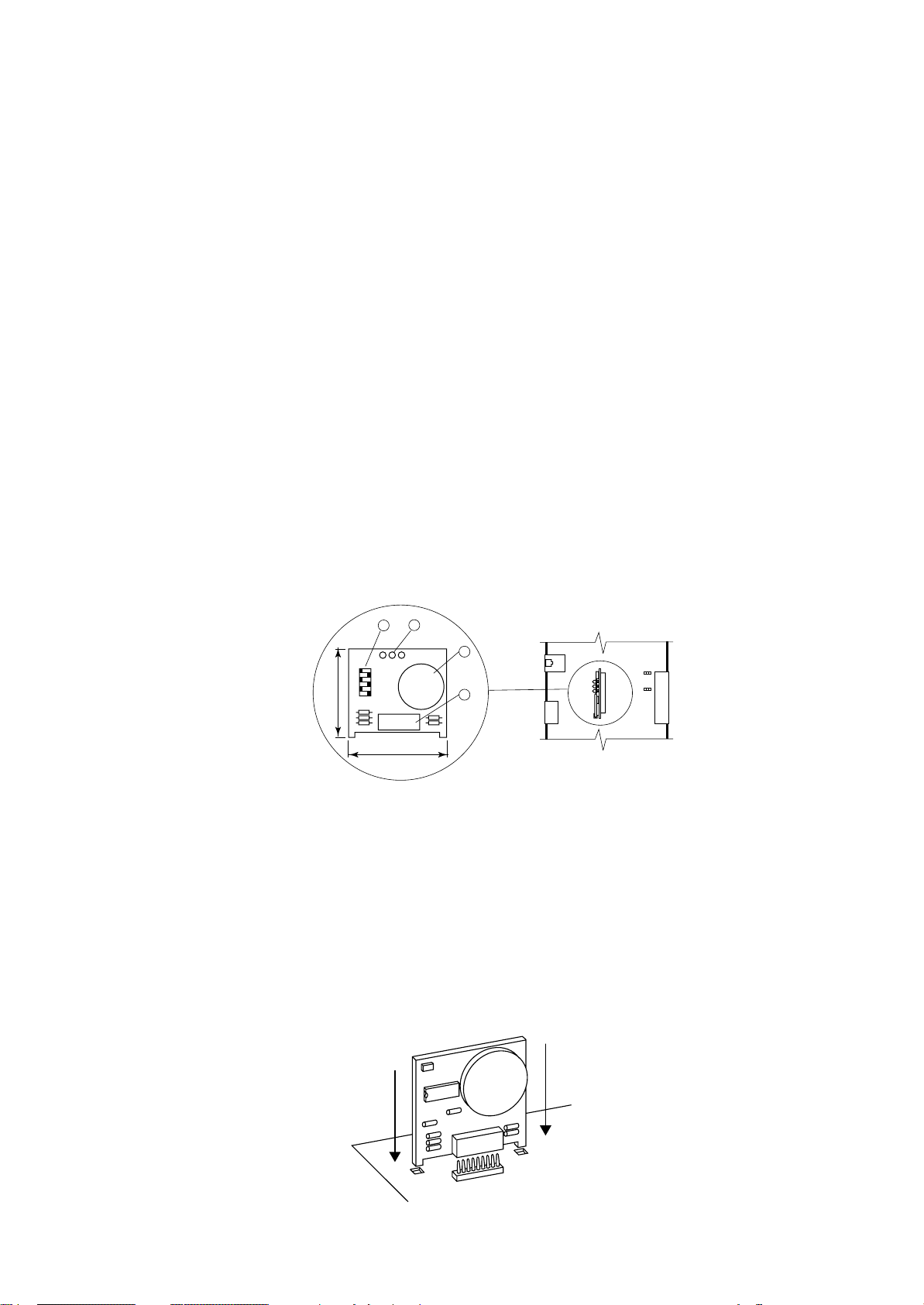
SCHEDE A MICROPROCESSORE - BOARD "A" E "B"
Il sistema di controllo può essere costituito da due schede
elettroniche; la BOARD "A" e la BOARD "B".
La BOARD "A" è la scheda principale ed è dotata di set di
morsetti estraibili necessari alla connessione verso i dispositivi controllati (ad esempio: valvole, compressori, ventilatori, ecc.).
Il programma di gestione è memorizzato su eprom mentre
i parametri impostati sono memorizzati su uno speciale
componente elettronico (Eeprom), che consente il mantenimento dei dati anche in caso di mancanza di alimentazione (senza il bisogno di una batteria di mantenimento).
La scheda BOARD "A" permette anche la connessione
alla rete locale LAN costituita da più schede e più terminali ed il collegamento verso la linea seriale di supervisione/
teleassistenza secondo lo standard RS485 e protocollo di
comunicazione RC-com.
Scheda BOARD "B" è identica alla precedente ed è dota-
ta di set di morsetti estraibili per la remotizzazione dei singoli allarmi e la gestione di alcuni componenti nelle unità
con doppio circuito frigorifero.
16 15
MICROPROCESSOR BOARDS - BOARD "A" AND "B"
The control system can be fitted with two electronic cards;
BOARD "A" and BOARD "B".
BOARD "A" is equipped with a set of plug-in connectors
necessary to connect the board to the controlled devices (e.g. valves, compressors, fans, etc.).
The program is written in the eprom, while the set
parameters are permanently stored (even in case of
power failure) into a special electronic component named
Eeprom.
The BOARD "A" can be linked to a LAN local network,
made by more boards and terminals, or to a supervisory/telemaintenance system via serial line through the
RS485 standard and the new RC-com communication
protocol.
BOARD "B" is equal to the previous one and is equipped
with a set of plug-in connectors for alarms remotization
and for the management of same components in unit with
double cooling circuit.
14
292
J17
J11
J20
J21
J22
J24
J19
FUSE
1
J9 J8
3
2
1
J29
J28
J15
J14
1
1
1
K11
K10
K9
1
K8
K7
K6
K13
K1
K2
K3
K4
K5
K12
RS485
3
2
1
3
2
1
3
1
2
1
321
321
1
1
1
1
1
B8
J1
+24Vcc
B7
B6
AVSS
B5
B4
AVSS
J2
B3
B2
AVSS
B1
IDCM2
ID10
ID9
J3
ID8
ID7
ID6
IDCM1
ID5
ID4
J4
ID3
ID2
ID1
C1
NO1
------
J5
C2
NO2
C3
NO3
-----C4
NO4
------
J6
C5
NO5
-----C12
NO12
13
12
11
10
9
1
G
2
3
G0
GND
RX/TX-
RX/TX+
4
5
VG0
6
7
8
VG1
Y1
Y0
ID11-230Vac
ID11-24Vac
ID11-R
----------ID12-R
ID12-24Vac
ID12-230Vac
NO11
C11
NC11
------
NO10
C10
NC10
-----NO9
C9
NC9
NO8
C8
-----NO7
C7
-----NO6
C6
------
NO13
C13
131
38
Fig. 1
8
RC GROUP - 149_ItEn.0102
Page 9

MP2000 AIR CONDITIONERS
Sistema di controllo a microprocessore per condizionatori d'aria •
Air conditioners microprocessor control system
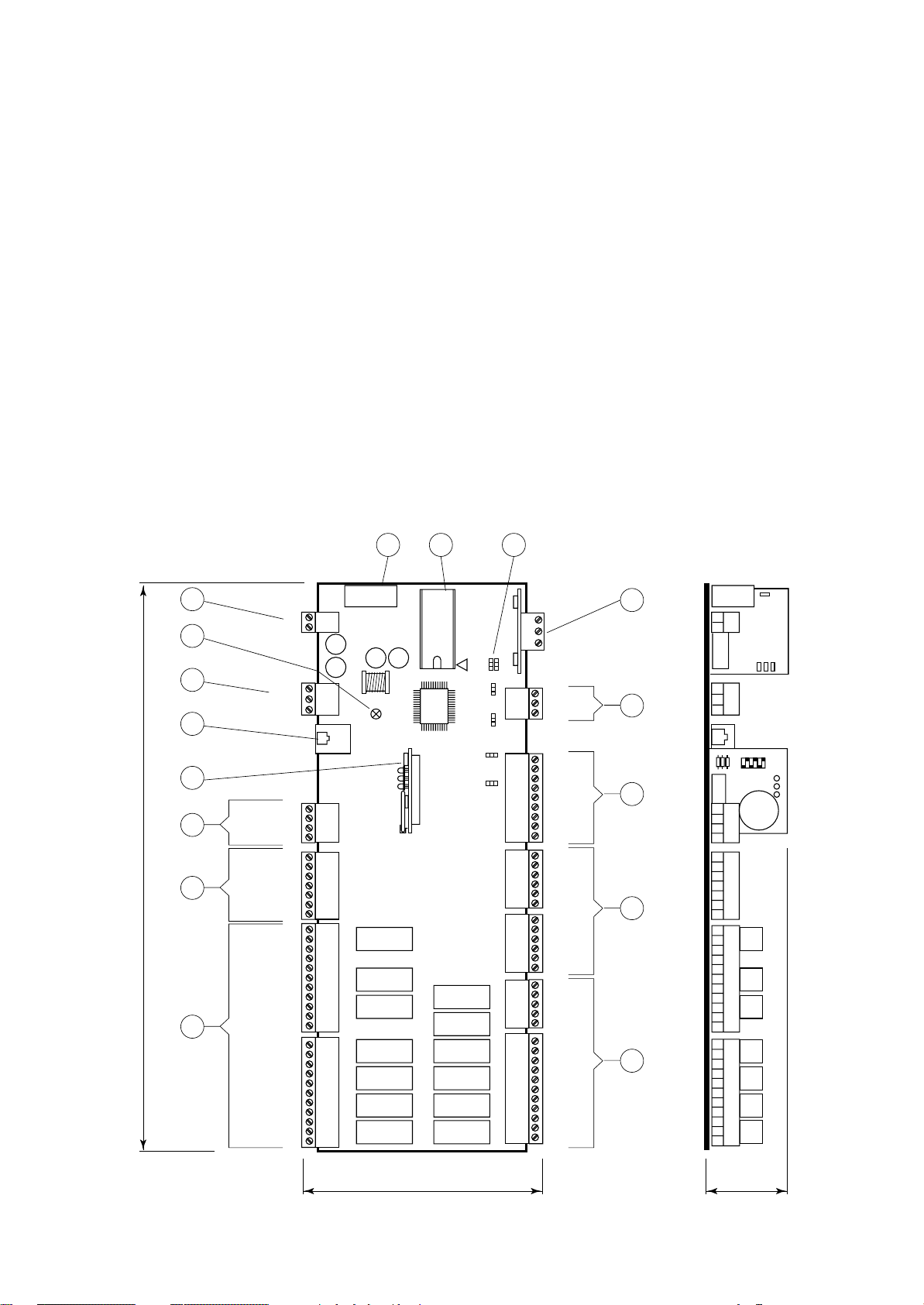
1. Connettore per alimentazione 24Vac o 24Vdc (+10% /
-15%) 50/60 Hz - 15VA.
2. LED giallo indicante presenza tensione.
3. Connettore a morsetti estraibili per rete LAN.
4. Connettore telefonico per connessione terminale.
5. Connettore per scheda indirizzamento "ADDR" fornita
di serie.
Scheda indirizzamento+orologio "ADDR+CK" a richiesta.
6. Uscite analogiche 0÷10Vdc optoisolate
• Y: Uscite analogiche 1 e 2, carico max 1kΩ (10mA).
• VG1: Alimentazione esterna per uscite analogiche
(24Vac o 24Vdc).
• VG0: Riferimento per l’alimentazione e per il segna-
le delle uscite analogiche Y0 e Y1.
7. Ingressi digitali optoisolati:
• ID11-230Vac, ID12-230Vac: Ingressi digitali 11 e 12
per segnali a 230Vac.
• ID11-24Vac, ID12-24Vac: Ingressi digitali 11 e 12 per
segnali a 24Vac o 24Vdc ±15%.
• ID11-R, ID12-R: riferimento comune per ingressi di-
gitali ID11 e ID12.
Evitare di portare segnali a 230Vac sul morsetto per
24Vac, pena danneggiamento della scheda stessa.
8. Uscite digitali 2500VA - 250Vac - 10A resistivi:
• NO: Contatto normalmente aperto.
• NC: Contatto normalmente chiuso.
• C: Contatto comune.
9. Uscite digitali 250Vac - 10A resistivi:
• NO: Contatto normalmente aperto.
• C: Contatto comune per il contatto.
10. Ingressi digitali optoisolati 24Vac o 24Vdc (10mA):
• ID: Ingressi digitali 1÷10.
• IDCM1: Riferimento comune ingressi digitali 1÷5.
• IDCM2: Riferimento comune ingressi digitali 6÷10.
11. Ingressi analogici:
• B: Ingresso analogico 1÷6.
• AVSS: riferimento comune degli ingressi analogici B.
• Da B1 a B4 accettano sonde NTC. B5 e B6 sono
selezionabili per sonde con segnale 0÷1Vdc o
4÷20mA tramite ponticelli.
12. Ingressi analogici:
• B: Ingresso analogico 7 e 8.
• +24Vdc: Alimentazione sonde attive e sensori di pres-
sione 4÷20mA (max 80mA).
• Selezionabili per sonde con segnale 0÷1Vdc o
4÷20mA tramite ponticelli.
13. Scheda porta seriale RS485 optoisolata (a richiesta).
14. Ponticelli per impostazioni:
• J8 in posizione 2-3.
• J9 in posizione 2-3.
• J14 selezione dell’ingresso analogico B5
1-2=4÷20mA, 2-3=0÷1Vdc.
• J15 selezione dell’ingresso analogico B6
1-2=4÷20mA, 2-3=0÷1Vdc.
• J28 selezione dell’ingresso analogico B7
1-2=4÷20mA, 2-3=0÷1Vdc.
• J29 selezione dell’ingresso analogico B8
1-2=4÷20mA, 2-3=0÷1Vdc.
15. Eprom contenente programma applicativo.
16. Fusibile 250Vac, 2A ritardato (2TA).
1. 24Vac or 24Vdc power supply connector (+10% / -15%)
50/60 Hz - 15VA.
2. Yellow LED for voltage presence indication.
3. Plug-in connector for LAN network.
4. Telephone-type connector for teminal connection.
5. Connector for address card "ADDR" (standardly supplied).
On request address+clock card "ADDR+CK".
÷
6. Analog outputs 0
• Y: Analog outputs 1 and 2, max load 1k
• VG1: External power supply for analog outputs (24Vac
or 24Vdc).
• VG0: Reference for power supply and analog outputs
signals Y0 and Y1.
7. Opto-insulated digital inputs:
• ID11-230Vac, ID12-230Vac: Digital inputs no. 11
and 12 for 230Vac signals.
• ID11-24Vac, ID12-24Vac: Digital inputs no. 11 and
12 for 24Vac or 24Vdc
• ID11-R, ID12-R: Common references for digital inputs ID11 and ID12.
Never connect the 230Vac signals to the 24Vac terminal; you damage the main board.
8. Digital outputs 2500VA - 250Vac - 10A resistive load:
• NO: Normally open contact.
• NC: Normally closed contact.
• C: Common contact.
9. Digital outputs 250Vac - 10A resistive load:
• NO: Normally open contact.
• C: Common contact.
10. Opto-insulated digital inputs 24Vac or 24Vdc (10mA):
• ID: Digital inputs 1
• IDCM1: Common reference for digital inputs 1
• IDCM2: Common reference for digital inputs 6
11. Analog inputs:
• B: Analogue input 1÷6.
• AVSS: Common reference of the analogue inputs B.
• From B1 to B4 preset to accept NTC sensors. B5 and
B6 selectable to accept either 4
signals through jumper.
12. Analog inputs:
• B: Analogue input 7 and 8.
• +24Vdc: Active probes and pressure probes 4
feeding (max 80 mA).
• Selectable to accept either 4÷20mA or 0÷1Vdc sig-
nals, through jumper.
13. Opto-insulated RS485 serial port (optional).
14. Jumpers for settings:
• J8 in position 2-3.
• J9 in position 2-3.
• J14 - B5 analog input selection
÷
20mA, 2-3=0÷1Vdc.
1-2=4
• J15 - B6 analog input selection
1-2=4÷20mA, 2-3=0÷1Vdc.
• J28 - B7 analog input selection
÷
20mA, 2-3=0÷1Vdc.
1-2=4
• J29 - B8 analog input selection
1-2=4÷20mA, 2-3=0÷1Vdc.
15. Eprom with application program.
16. 250Vac fuse, 2A delayed (2TA).
10Vdc opto-insulated
±
15% signals.
÷
10.
÷
20mA or 0÷1Vdc
Ω
(10mA).
÷
÷
5.
÷
10.
20mA
RC GROUP - 149_ItEn.0102
9
Page 10
MP2000 AIR CONDITIONERS
Sistema di controllo a microprocessore per condizionatori d'aria •
Air conditioners microprocessor control system
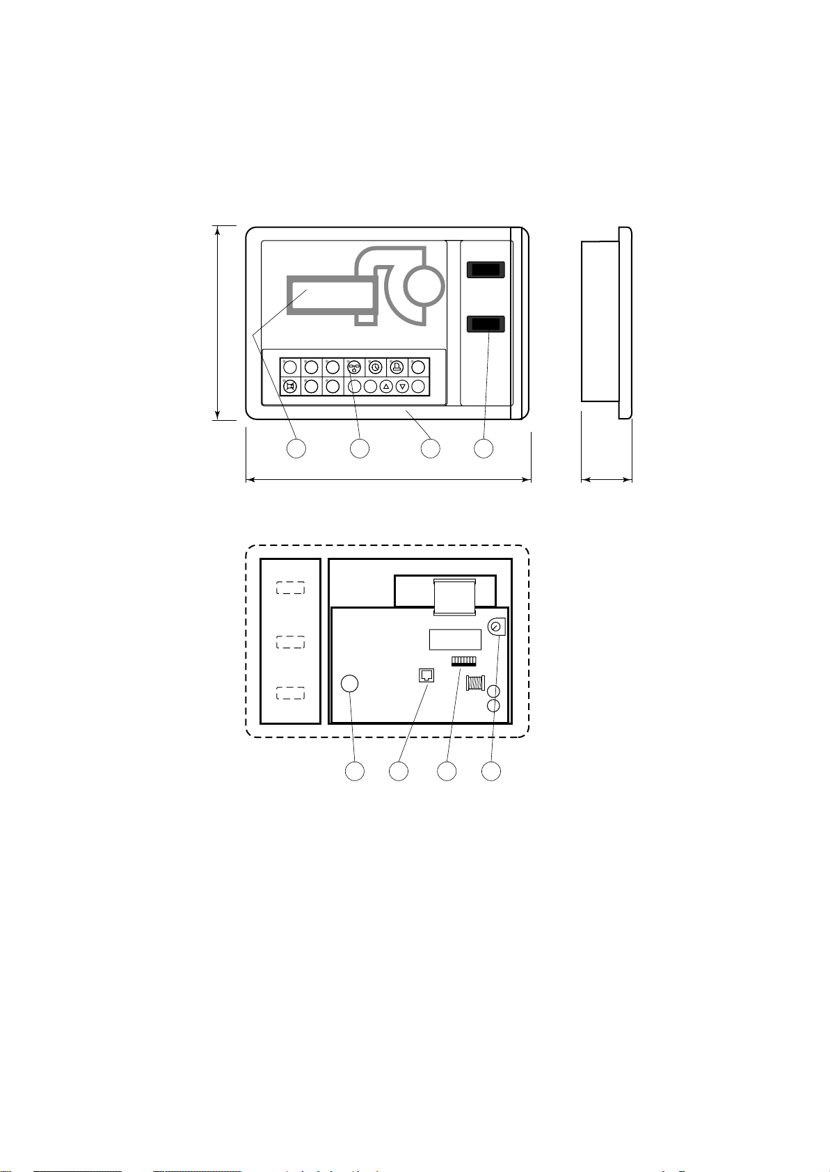
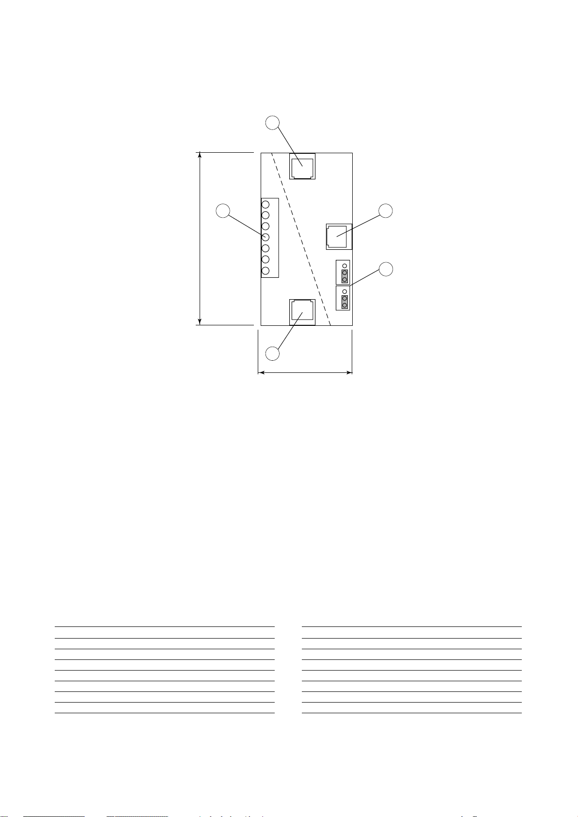
TERMINALE
Il terminale è dotato di display, tastiera e LED per rendere
possibile la programmazione dei parametri di controllo (set
points, differenziali, soglie di allarme) e le operazioni fondamentali da parte dell’utente (on/off, visualizzazione dei
valori controllati).
La connessione del
VISTA FRONTALE TERMINALE
TERMINAL FRONTAL VIEW
terminale alla scheda
BOARD "A" non è necessaria per il funzio-
MP2000
namento a regime
del controllore; può
essere utilizzata per
la programmazione
iniziale dei parametri
fondamentali e consente le seguenti funzioni:
185
HOME SET PRG
1
234
STATUS
ALARM
567
RC GROUP
E
MEMO
I
• la programmazione iniziale della
macchina con accesso protetto da
password per ga-
270
rantirne la sicurezza.
• la possibilità di modificare in qualsia-
VISTA POSTERIORE TERMINALE SENZA COPERCHIO
TERMINAL BACK VIEW WITHOUT COVER
si momento i parametri fondamentali
di funzionamento
protetti da
password.
• la visualizzazione
tramite display degli allarmi rilevati e
la loro segnalazione acustica per
mezzo di un
cicalino.
• la visualizzazione
tramite LED delle
funzioni attive.
• la visualizzazione
5 6 8
di tutte le grandezze misurate.
TERMINAL
The terminal is complete with display, keyboard and LED
indicators allowing you to easily set the main control
parameters (setpoints, differential zone, alarm thresholds)
and carry out the main working operations (on/off, display-
ing controlled variables).
Connection be-
MAN - O - AUT
tween terminal and
BOARD "A" is not
necessary in normal
working conditions.
SUMMER - WINTER
It is necessary only
for initial basic parameters program-
ON/OFF
ENTER
ming with the following functions:
• initial programming
procedure with access protected by a
1
43 2
password.
• possibility of
55
changing the basic
operation parameters any time, without stopping the program.
• indication of any
alarm condition via
acoustic and visual
signals (buzzer and
alarm messages appearing on the dis-
12345678
on
play).
• visualization of the
active functions by
means of LED indicators.
• visualization of the
measured variables.
7
Fig. 2
1. Terminale.
2. Tastiera terminale.
3. Display terminale, 4x20 caratteri.
4. Interruttori ausiliari unità.
5. Suoneria.
6. Connettore telefonico per connessione a scheda
BOARD "A".
7. Dip-switch per impostazione indirizzo rete LAN.
8. Potenziometro per regolazione contrasto display.
10
1. Terminal.
2. Terminal keyboard.
3. Terminal display, 4x20 characters.
4. Auxiliary unit switches.
5. Buzzer.
6. Telephone-type connector for connection to BOARD
"A".
7. Dip-switch for LAN network address setup.
8. Potentiometer for display contrast calibration.
RC GROUP - 149_ItEn.0102
Page 11
MP2000 AIR CONDITIONERS
Sistema di controllo a microprocessore per condizionatori d'aria •
Air conditioners microprocessor control system
SCHEDA "ADDR"
SCHEDA INDIRIZZAMENTO
La scheda è installata di serie sulla BOARD "A" e sull'eventuale BOARD "B".
La scheda "ADDR" definisce il codice di indirizzamento
necessario al microprocessore per determinare la funzione e l'eventuale posizione nella rete LAN della scheda
BOARD su cui è installata.
Tramite i Dip-switch 1÷6 è possibile impostare il codice di
indirizzamento della scheda.
I LEDs "R" "G" "V" indicano:
"R"incompatibilità hardware (luce rossa intermittente).
incompatibilità software (luce rossa).
"G"trasmissione dati in corso (luce gialla intermittente).
"V" settaggio corretto per la rete LAN (luce verde).
Il LED verde rimane acceso anche se non è prevista la
rete LAN.
1
2
off
1
GV
R
6
39
"ADDR" BOARD
ADDRESS BOARD
This board is standardly installed on BOARD "A" or on the
eventual BOARD "B".
The "ADDR" board allows to fix the address code necessary to the microprocessor to determine the function and
the eventual position in the LAN network of the BOARD on
which it is installed.
÷
Through the Dip-switch 1
6 it is possible to set the board
address code.
The "R" "G" "V" LEDs show:
"R"hardware not compatible (blinking red light).
software not compatible (red light).
"G"data transmission (blinking yellow light).
"V" correct set for the LAN network (green light).
The green LED keeps lighting even if the LAN network
is not foreseen.
J19
3
1
J20
J15
J14
J2
50
1.LEDs "R" "G" "V".
2.Dip-switch per impostazione codice indirizzamento.
3.Connettore.
Fig. 3
1."R" "G" "V" LEDs.
2.Dip-switch for address setting.
3.Connector.
RC GROUP - 149_ItEn.0102
11
Page 12
MP2000 AIR CONDITIONERS
Sistema di controllo a microprocessore per condizionatori d'aria •
Air conditioners microprocessor control system
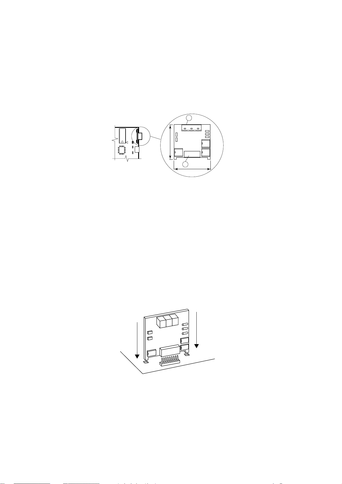
SCHEDA "ADDR+CK"
SCHEDA INDIRIZZAMENTO + OROLOGIO
La scheda deve essere installata esclusivamente sulla
BOARD "A" e rimpiazza la scheda "ADDR".
La scheda è equipaggiata con i Dip-switch per l'impostazione dei codici di indirizzamento, con l'orologio a tempo
reale e relativa batteria al litio ricaricabile.
In mancanza di alimentazione, la batteria al litio ricaricabile mantiene attivo l'orologio per oltre un mese (tempo di
carica batteria 12h - 45 mA/h).
La funzione "ADDR" definisce il codice di indirizzamento
necessario al microprocessore per determinare la funzione e l'eventuale posizione nella rete LAN della scheda
BOARD su cui è installata.
Tramite i Dip-switch 1÷6 è possibile impostare il codice di
indirizzamento della scheda.
La funzione "CK" consente la visualizzazione di data ed
ora correnti, data ed ora degli allarmi intervenuti e l'abilitazione della funzione CHRONO (attivazione/spegnimento
unità su fasce orarie).
I LEDs "R" "G" "V" indicano:
"R"incompatibilità hardware (luce rossa intermittente).
incompatibilità software (luce rossa).
"G"trasmissione dati in corso (luce gialla intermittente).
"V" settaggio corretto per la rete LAN (luce verde).
Il LED verde rimane acceso anche se non è prevista la
rete LAN.
"ADDR+CK" BOARD
ADDRESS + CLOCK BOARD
This board must be installed on BOARD "A" only and
replaces the "ADDR" card.
The board is equipped with Dip-switch for the address code
sets and with a real time clock with rechargeable lithium
battery.
In case of power failure, the rechargeable lithium battery
will make the board work for more than one month (rechargeable time 12h - 45 mA/h).
The "ADDR" function allows to fix the address code necessary to the microprocessor to determine the function and
the eventual position in the LAN network of the BOARD on
which it is installed.
÷
Through the Dip-switch 1
6 it is possible to set the board
address code.
The "CK" function allows the current date and time display,
the date and time display of the intervened alarms and the
enabling of the CHRONO function (time-band units control
action).
The "R" "G" "V" LEDs show:
"R"hardware not compatible (blinking red light).
software not compatible (red light).
"G"data transmission (blinking yellow light).
"V" correct set for the LAN network (green light).
The green LED keeps lighting even if the LAN network
is not foreseen.
1
2
off
GV
R
1
6
39
50
Fig. 4
1.LEDs "R" "G" "V".
2.Dip-switch per impostazione codice indirizzamento.
3.Pila al litio per orologio.
4.Connettore.
INSTALLAZIONE SCHEDA
Istruzioni per il corretto montaggio della scheda
"ADDR+CK" sulla scheda BOARD "A":
• Togliere l’alimentazione al sistema prima di inserire/rimuovere la scheda.
• Verificare la posizione esatta prima dell'inserimento della scheda.
• La scheda deve essere infilata negli appositi fori che si trovano ai lati dei contatti.
• Assicurarsi che la scheda sia perfettamente verticale rispetto al connettore per
evitare di danneggiare i contatti.
• Il connettore a pettine deve essere inserito perfettamente fino in fondo.
3
4
J19
1
J20
J15
J14
J2
1.LEDs "R" "G" "V".
2.Dip-switch for LAN network address setting.
3.Lithium battery for real time clock.
4.Connector.
BOARDS INSTALLATION
Instruction for a correct installation of the board "ADDR+CK"
on BOARD "A":
• Switch OFF the system before mounting or removing
the board.
• Identify exactly where the board must be
positioned.
• Insert the board into its dedicated holes.
• When mounting the board make sure it is
perfectly vertical in relation to the main
card in order not to damage the contacts.
• The pin connector must be properly
plugged into the connector.
12
Fig. 5
RC GROUP - 149_ItEn.0102
Page 13
MP2000 AIR CONDITIONERS
Sistema di controllo a microprocessore per condizionatori d'aria •
Air conditioners microprocessor control system
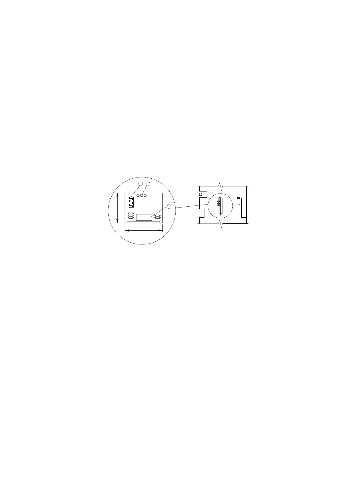
SCHEDA "T"
Questa scheda è essenzialmente un derivatore a T e trova
impiego nel collegamento al terminale remoto "T".
Come indicato in figura la scheda è
equipaggiata con 3 connettori telefonici e con una morsettiera.
Utilizzando la scheda "T" per il
collegamento al Terminale Remoto è necessario predisporre i ponticelli J14 - J15 in posizione 1-2 per
rendere l'alimentazione elettrica
diponibile su tutti i connettori (A-BC-M).
1.Connettore telefonico disponibile per collegamento Board "A" o
Terminale Remoto "T" o Terminale a bordo macchina.
2.Connettore telefonico disponibile per collegamento Board "A" o
Terminale Remoto "T" o Terminale a bordo macchina.
3.Morsettiera per connessione
scheda "T" del Terminale Remoto "T".
4.Connettore telefonico disponibile per collegamento Board "A" o
Terminale Remoto "T" o Terminale a bordo macchina.
5.Ponticelli di settaggio.
32
75
"T" BOARD
This board is essentially a T-derivator used for "T" remote
terminal connection.
1
C
0
1
2
3
M
4
5
6
4
A
35
B
J15
3
2
1
3
2
1
J14
As shown in the picture, the board
is equipped with 3 telephone connectors and terminals.
By using the "T" board for connection to a Remote Terminal, it
is necessary to set the J14-J15
jumpers on 1-2 position. In this
way the electrical feeding is available on all connectors (A-B-CM).
1. Available telephone connector
for Board "A" or "T" Remote Terminal or unit Terminal connec-
5
tion.
2. Available telephone connector
for Board "A" or "T" Remote Terminal or unit Terminal connection.
3. Terminals for "T" board on "T"
Remote Terminal.
4. Available telephone connector
for Board "A" or "T" Remote Terminal or unit Terminal connection.
5. Setting jumpers.
Fig. 6
SETTAGGIO PONTICELLI J14 - J15
Posizione 1 - 2
I tre connettori telefonici A - B - C ed il connettore a vite M
sono posti in parallelo. L'alimentazione è disponibile su
tutti i connettori.
Posizione 2 - 3
L'alimentazione elettrica presente sui connettori B - C è
separata da quella presente sui connettori A - M.
La connessione LAN non viene interrotta tra i vari connettori.
Nel caso i due ponticelli J14 - J15 siano posizionati in
modo differente il derivatore NON funziona.
Conn.M Conn.A-B-C
0 == Calza cavo schermato
1 1 +VRL = 30Vdc
2 2 GND
3 3 Rx- / Tx4 4 Rx+ / Tx+
5 5 GND
6 6 +VRL = 30Vdc
JUMPERS SETTING J14 - J15
Set 1 - 2
The three telephone connectors A - B - C and the screw
connector M are linked in parallel. The power supply is
available on all connectors.
Set 2 - 3
The electrical feeding of B - C connectors is separate from
the one of A - M connectors.
The LAN network is not interrupted among the several
connectors.
In case the two jumpers J14 - J15 are set in different
position, the T-derivator does NOT work.
Conn.M Conn.A-B-C
0 == Braiding of shielded wire
1 1 +VRL = 30Vdc
2 2 GND
3 3 Rx- / Tx4 4 Rx+ / Tx+
5 5 GND
6 6 +VRL = 30Vdc
Quando si usa un cavo schermato il contenitore metallico
del derivatore deve essere collegato a terra.
RC GROUP - 149_ItEn.0102
When a shielded cable is used, the metallic case of the T
derivator must be earthed.
13
Page 14
MP2000 AIR CONDITIONERS
Sistema di controllo a microprocessore per condizionatori d'aria •
Air conditioners microprocessor control system
PORTA SERIALE RS485
La scheda deve essere installata sulla BOARD "A".
La porta seriale permette l'interfacciamento con una rete
RS485, la scheda garantisce l'optoisolamento del controllo rispetto alla rete seriale RS485.
Il baud-rate massimo è di 19.200 baud, impostabile via
software da tastiera.
Il collegamento all'MP2000 si ottiene posizionando la scheda nel corrispondente connettore a pettine.
RS485
J9 J8
J29
J1
J28
Fig. 7
1.Morsettiera estraibile
2.Connettore.
INSTALLAZIONE SCHEDA
Istruzioni per il corretto montaggio della scheda "RS485"
sulla scheda BOARD "A":
• Togliere l’alimentazione al sistema prima di inseri-
re/rimuovere la scheda.
• Verificare la posizione esatta prima dell'inserimento della scheda.
• La scheda deve essere infilata negli appositi fori che si
trovano ai lati dei contatti.
• Assicurarsi che la scheda sia perfettamente verticale rispetto al connettore per evitare di danneggiare i contatti.
• Il connettore a pettine deve essere inserito perfettamente
fino in fondo.
RS485 SERIAL PORT
This board must be installed on BOARD "A".
The serial port allows interface to a RS485 connection.
This card ensures the controller opto-insulation to the
connection network.
The max baud-rate is 19.200 baud settable via software.
The connection to the controller is obtained when you insert
the card into the relevant plug-in connector.
1
GND RX+
RX-
TX+
TX-
42
2
40
1.Plug-in connector
2.Connector.
BOARD INSTALLATION
Instruction for a correct installation of the board "RS485" on
BOARD "A":
• Switch OFF the system before mounting or removing
the board.
• Identify exactly where the board must be positioned.
• Insert the board into its dedicated holes.
• When mounting the board make sure it is perfectly vertical
in relation to the main card in order not to damage the
contacts.
• The pin connector must be properly plugged into the
connector.
14
Fig. 8
RC GROUP - 149_ItEn.0102
Page 15
MP2000 AIR CONDITIONERS
Sistema di controllo a microprocessore per condizionatori d'aria •
Air conditioners microprocessor control system
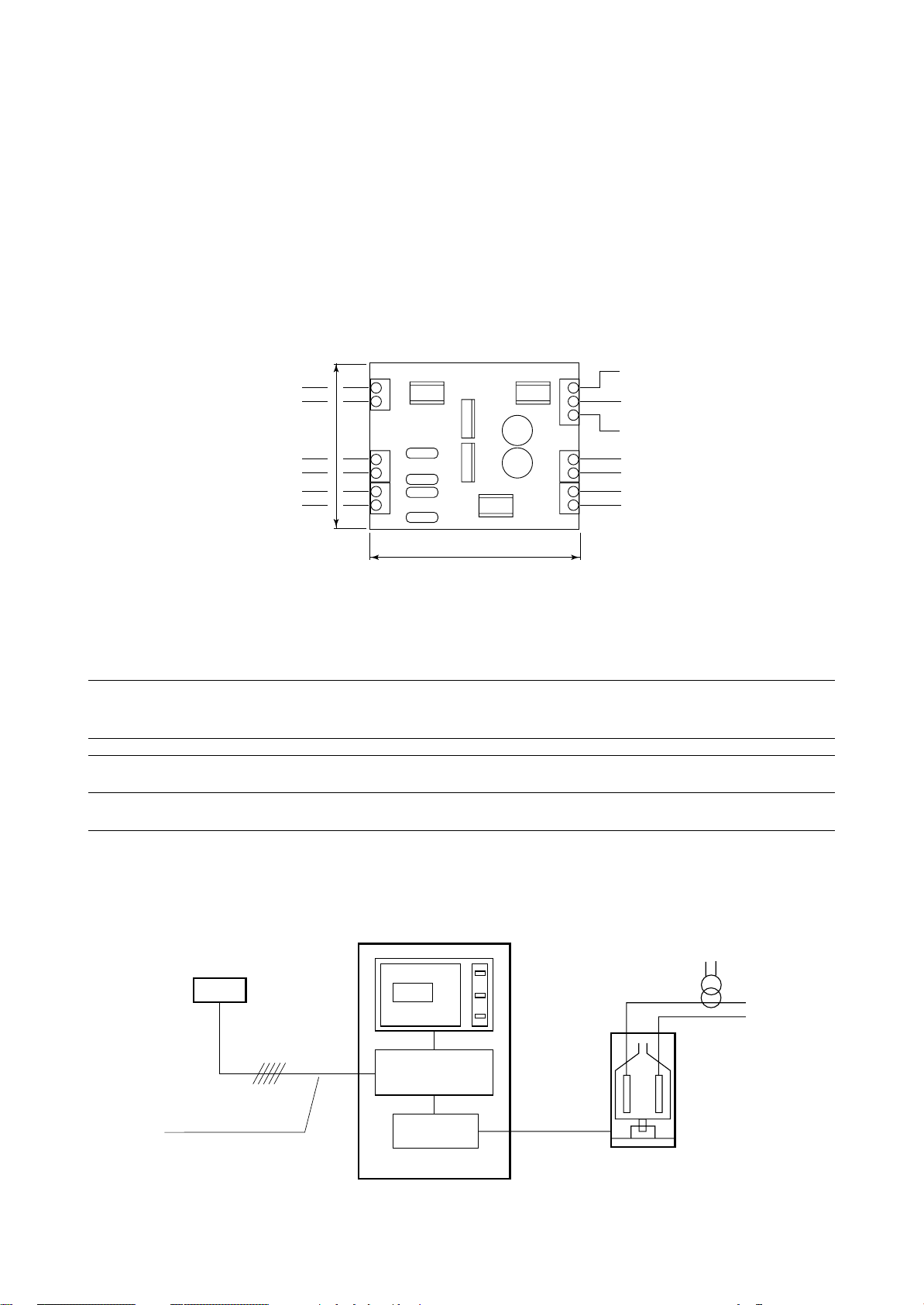
SCHEDA UMIDIFICATORE
Questa interfaccia è essenzialmente un convertitore di
segnale per permettere di controllare i parametri dell'eventuale umidificatore installato sull'unità quali: conducibilità
dell'acqua, livello acqua nel cilindro e assorbimento corrente.
L'alimentazione elettrica della scheda deve essere prelevata esclusivamente dal trasformatore di alimentazione
della scheda BOARD "A".
I sensori di rilevamento non hanno polarità.
La scheda umidificatore è installata all'interno del quadro
elettrico dell'unità in prossimità della BOARD.
67
T1
T2
C1
C2
J3
J2
L1
L2
J1
Sensore corrente (Ax0,2 = valore in Vac)
(vedi trasformatore amperometrico TA20/4)
Current sensor (Ax0,2 = valore in Vac)
(see amperometric transformer 20/4)
Sensore conducibilità
Conductivity sensor
Sensore livello
Level sensor
Fig. 9
HUMIDIFIER BOARD
This interface card is essentially a signal converter to allow
the parameters control of the humidifier eventually installed
on the unit, such as: water conductivity, water level in the
cylinder and current absorption.
It is compulsory to take electric feeding for this card from the
transformer of the BOARD "A".
The sensors do not have polarity.
The humidifier board is installed inside the unit electric box
close to the BOARD.
Uscita analogica 0÷1Vdc - Conducibilità
Analogical output 0÷1Vdc - Conductivity
Riferimento uscite analogiche
Analogical output reference
Uscita analogica 0÷1Vdc - Corrente
Analogical output 0÷1Vdc - Current
Alimentazione elettrica 24Vac
Power supply 24Vac
Uscita digitale alto livello acqua
High water level digital output
84
J6
B8
G0
B7
J5
G
G0
O1
O2
J4
CARATTERISTICHE UMIDIFICATORI
HUMIDIFIER CHARACTERISTICS
Modello Tensione Capacità Potenza Corrente
Model Voltage Capacity Power Current
kg/h kW A
L201MA 230.1.50 2 1,4 6,1
F401TA 230.3.50 3 2,2 5,5
F401TA 400.3.50 5 3,6 5,2
E401TA/1 230.3.50 8 5,8 14,5
E401TA/1 400.3.50 13 9,4 13,6
SCHEMA DI INSTALLAZIONE
Sensore Temperatura/Umidità
Temperature/Humidity sensor
Condizionatore
Air conditioner
TERMINAL
BOARD "A"
INSTALLATION DIAGRAM
Trasformatore amperometrico
Amperometric transformer
Cavo sez. > 0,5mm2
Cable sect. > 0,5 mm2
RC GROUP - 149_ItEn.0102
HUMIDIFIER
BOARD
Umidificatore
Humidifier
Fig. 10
15
Page 16
MP2000 AIR CONDITIONERS
Sistema di controllo a microprocessore per condizionatori d'aria •
Air conditioners microprocessor control system
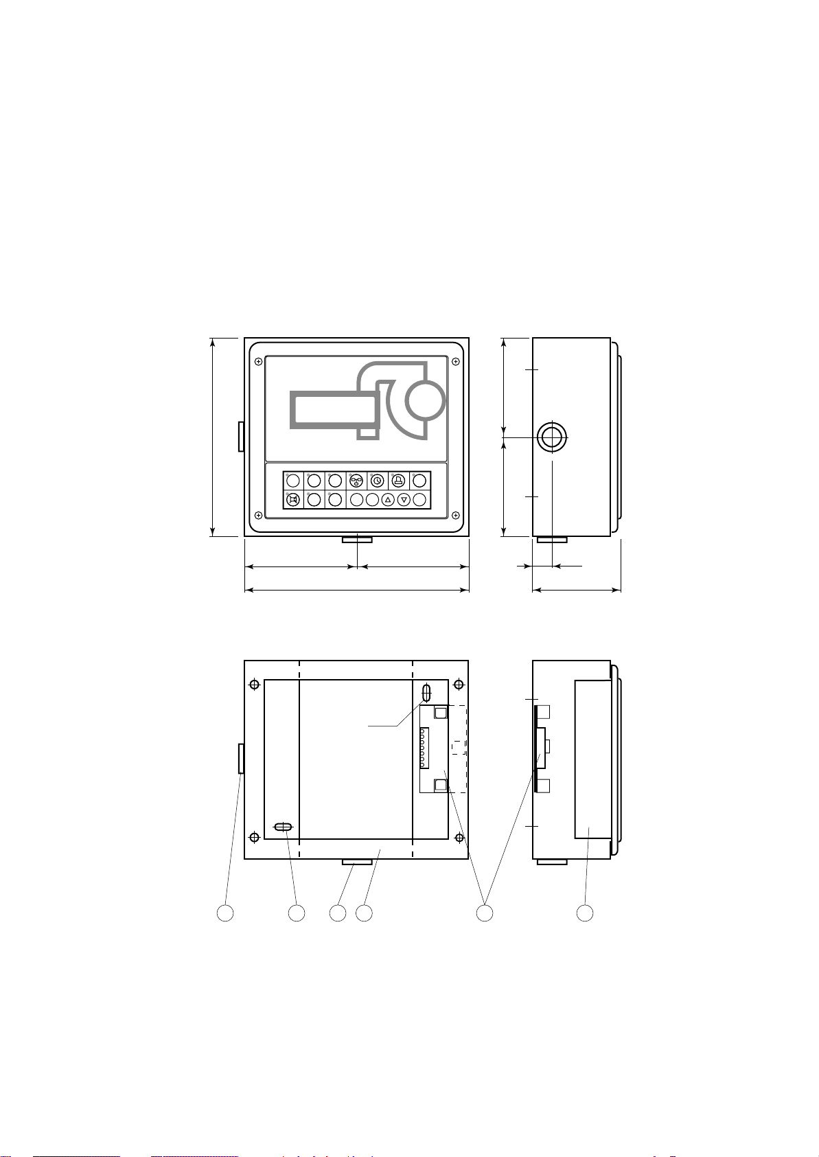
TERMINALE REMOTO "T"
Il terminale remoto "T" viene fornito in kit (kit terminale remoto "T") ed è composto da una scatola di contenimento
in lamiera verniciata contenente il TERMINALE e la scheda "T" per la connessione all'unità.
La scatola di contenimento è predisposta per il fissaggio a
parete e presenta un'apertura nella parte posteriore per il
passaggio del cavo di collegamento tra la scheda "T" e
l'unità.
Il terminale è dotato di display, tastiera e LED per rendere
possibile la programmazione dei parametri di controllo (set
points, differenziali,
soglie di allarme) e le
operazioni fondamentali da parte del-
VISTA CON TERMINALE
VIEW WITH TERMINAL
l’utente (on/off, visualizzazione dei valori
controllati).
MP2000
Come per il terminale a bordo macchina,
il terminale remoto
consente le seguenti
funzioni:
• la programmazione iniziale della
180
HOME SET PRG
1
234
STATUS
ALARM
567
RC GROUP
E
MEMO
I
macchina con accesso protetto da
password per garantirne la sicurezza.
• la possibilità di modificare in qualsia-
==
VISTA SENZA TERMINALE
VIEW WITHOUT TERMINAL
205
si momento i parametri fondamentali
di funzionamento
protetti da
password.
• la visualizzazione
tramite display degli allarmi rilevati e
5x10
la loro segnalazione acustica per
mezzo di un
cicalino.
• la visualizzazione
tramite LED delle
funzioni attive.
• la visualizzazione
di tutte le grandezze misurate.
"T" REMOTE TERMINAL
The "T" remote terminal is supplied in kit ("T" remote
terminal kit) and includes a painted steel sheet box contained the TERMINAL and the "T" board for the connection
to the unit.
The box has a wall mounting predisposition and a back side
opening to allows the connection between the "T" board
and the remote unit.
The terminal is complete with display, keyboard and LED
indicators allowing you to easily set the main control
parameters (setpoints, differential zone, alarm thresholds)
and carry out the
main working operations (on/off, displaying controlled variables).
As described on unit
==
terminal, the remote
terminal allows the
following functions:
• initial programming
procedure with ac-
ON/OFF
ENTER
cess protected by a
password.
• possibility of changing the basic operation parameters any
time, without stop-
20
90
ping the program.
• indication of any
alarm condition via
acoustic and visual
signals (buzzer and
alarm messages appearing on the display).
• visualization of the
active functions by
means of LED indicators.
• visualization of the
measured variables.
1. Terminale.
2. Scheda "T".
3. Fori 5x10 per fissaggio a parete.
4. Scatola di contenimento.
5. Passacavo in gomma 16MV
16
4 2 135 5
Fig. 11
1. Terminal.
2. "T" board.
3. 5x10 holes for wall mounting.
4. Containing box.
5. Rubber fairlead 16MV
RC GROUP - 149_ItEn.0102
Page 17
MP2000 AIR CONDITIONERS
Sistema di controllo a microprocessore per condizionatori d'aria •
Air conditioners microprocessor control system
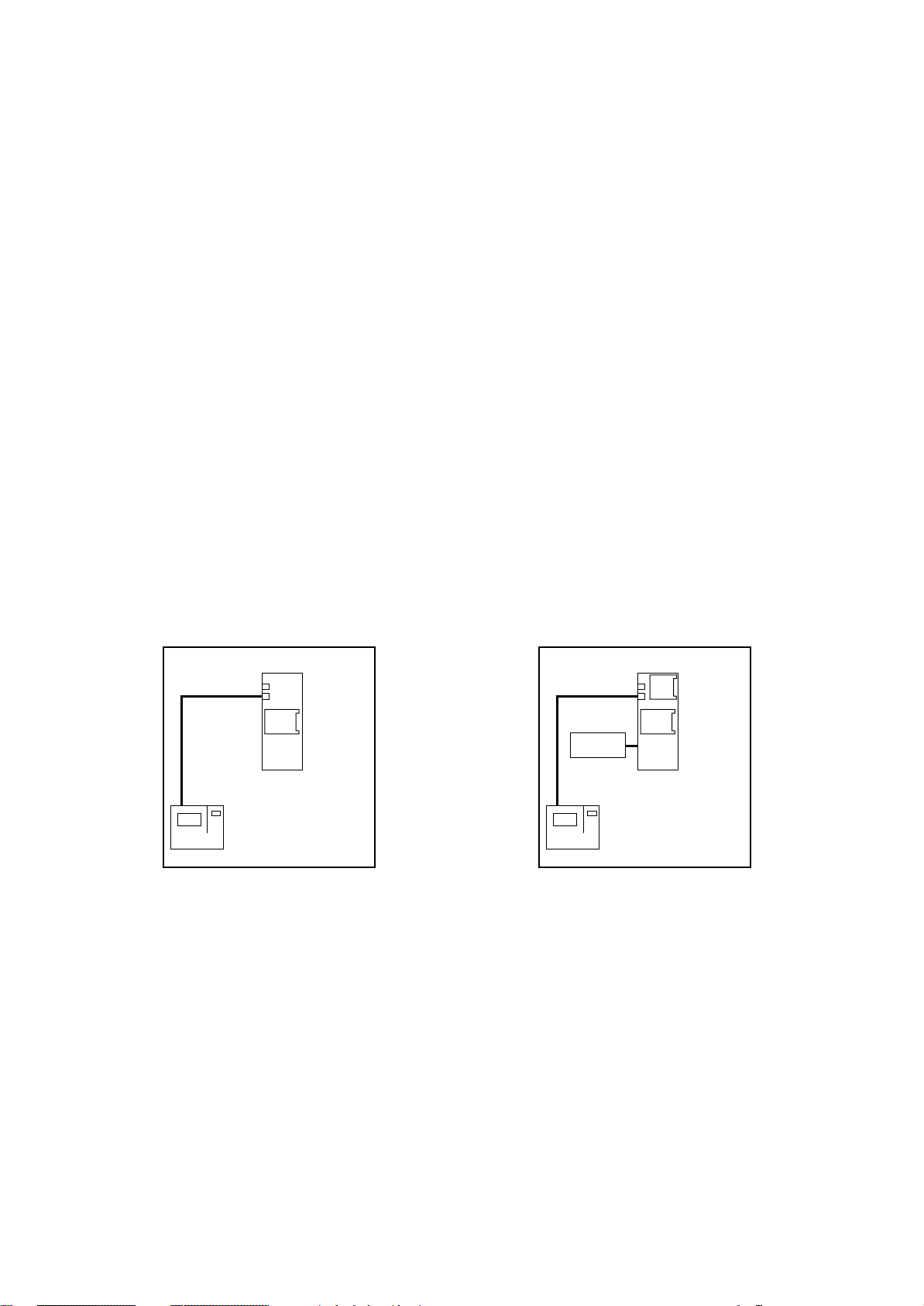
POSSIBILI CONFIGURAZIONI DEL SISTEMA MP2000
CONFIGURAZIONE CON BOARD "A" E TERMINALE A
BORDO MACCHINA
Questo tipo di configurazione è adatta per le seguenti unità:
- Condizionatori alimentati con acqua refrigerata
- Condizionatori equipaggiati con un compressore
- Condizionatori equipaggiati con due compressori su
unico circuito frigorifero.
Il sistema MP2000 comprende la scheda BOARD "A" con
la scheda "ADDR" ed il TERMINALE.
Con questa configurazione il sistema controlla totalmente
l'unità e visualizza sul display tutti gli stati di funzionamento
e gli eventuali allarmi intervenuti.
Per il corretto funzionamento del sistema è necessario
impostare i codici di indirizzamento, indicati tra parentesi
nella figura, sui dip-switch di ogni scheda:
- BOARD "A" codice "2"
- TERMINALE codice "1"
La remotizzazione degli allarmi è possibile solo tramite due
relè di Allarme Generale programmabili con contatto pulito.
A richiesta:
- Porta seriale "RS485"
- Scheda "ADDR+CK"
- Scheda "Umidificatore"
POSSIBLE CONFIGURATIONS OF THE
MP2000 SYSTEM
CONFIGURATION WITH BOARD "A" AND TERMINAL
ON UNIT
This configuration is suitable for the following units:
- Air conditioners with chilled water feeding,
- Air conditioners equipped with one compressor,
- Air conditioners equipped with two compressors working
on a single gas circuit.
The the MP2000 microprocessor control system includes
BOARD "A" with "ADDR" board and TERMINAL.
In this configuration, the system controls the unit showing
on the display all the unit working status and the eventual
intervened alarms.
For a correct system operation it is necessary to set the
address code, between brackets in the picture, on dipswitch of each board.
- BOARD "A" code "2"
- TERMINAL code "1"
The alarms remotization is possible only through two
General Alarm relays with voltage free contact.
On request:
- Serial port "RS485"
- Board "ADDR+CK"
- Board "Humidifier"
STANDARD
ADDR
BOARD
A
(2)
(1)
TERMINAL
CONFIGURAZIONE CON BOARD "A" E TERMINALE A
BORDO MACCHINA E/O REMOTO "T"
Questa configurazione presenta le stesse caratteristiche
della precedente ma consente la gestione dell'unità anche
dal TERMINALE REMOTO "T".
Per il corretto funzionamento del sistema è necessario
impostare i codici di indirizzamento, indicati tra parentesi
nella figura, sui dip-switch di ogni scheda:
- BOARD "A" codice "2"
- TERMINALE codice "1"
- TERMINALE REMOTO "T" codice "15"
La remotizzazione degli allarmi è possibile solo tramite due
relè di Allarme Generale programmabili con contatto pulito.
La scheda "T" del condizionatore è fornita non installata in
quanto, in caso di rete LAN, deve essere posizionata
sull'unità più vicina al TERMINALE REMOTO "T".
Il TERMINALE REMOTO "T" e la seconda scheda "T" sono
RC GROUP - 149_ItEn.0102
CONDIZIONATORE
AIR CONDITIONER
Fig. 12
OPTIONAL
RS
485
CK
Umidif.
Humidif.
(1)
TERMINAL
ADDR
BOARD
A
(2)
CONDIZIONATORE
AIR CONDITIONER
CONFIGURATION WITH BOARD "A" AND TERMINAL
ON UNIT AND/OR "T" REMOTE
This configuration has the same characteristics of the
previous one, but allows the unit management also from
the "T" REMOTE TERMINAL.
For a correct system operation it is necessary to set the
address code, between brackets in the picture, on dipswitch of each board.
- BOARD "A" code "2"
- TERMINAL code "1"
- "T" REMOTE TERMINAL code "15"
The alarms remotization is possible only through two
General Alarm relays with voltage free contact.
The air conditioner "T" board is supplied not installed
because, in case of LAN network, it has to be positioned on
the unit closest to the "T" REMOTE TERMINAL.
The "T" REMOTE TERMINAL and the second "T" board
17
Page 18
MP2000 AIR CONDITIONERS
Sistema di controllo a microprocessore per condizionatori d'aria •
Air conditioners microprocessor control system
installati nel box di contenimento per installazione a parete.
Il cavo di collegamento tra le due schede "T" è a cura del
Cliente (max 200m).
A richiesta:
- Porta seriale "RS485"
- Scheda "ADDR+CK"
- Scheda "Umidificatore"
- Detrazione TERMINALE - unità priva di TERMINALE e
controllata dal TERMINALE REMOTO "T".
STANDARD OPTIONAL
Terminale remoto "T"
"T" Remote terminal
TERMINAL
(15)
Scheda T
T board
(1)
TERMINAL
ADDR
BOARD
A
(2)
Scheda T
T board
CONDIZIONATORE
AIR CONDITIONER
are installed in the wall mounting box.
The connection cable between the two "T" boards is by
Customer care (200m max).
On request:
- Serial port "RS485"
- Board "ADDR+CK"
- Board "Humidifier"
- TERMINAL removal - unit without TERMINAL and controlled only by "T" REMOTE TERMINAL.
Terminale remoto "T"
"T" Remote terminal
TERMINAL
(15)
Scheda T
T board
Umidif.
Humidif.
(1)
TERMINAL
RS
485
CK
ADDR
BOARD
A
(2)
Scheda T
T board
CONDIZIONATORE
AIR CONDITIONER
OPTIONAL OPTIONAL
ADDR
BOARD
A
(2)
Scheda T
T board
CONDIZIONATORE
AIR CONDITIONER
Terminale remoto "T"
"T" Remote terminal
TERMINAL
(15)
Scheda T
T board
Umidif.
Humidif.
RS
485
CK
ADDR
BOARD
A
(2)
CONDIZIONATORE
AIR CONDITIONER
Fig. 13
Scheda T
T board
Terminale remoto "T"
"T" Remote terminal
TERMINAL
(15)
Scheda T
T board
18
RC GROUP - 149_ItEn.0102
Page 19
MP2000 AIR CONDITIONERS
Sistema di controllo a microprocessore per condizionatori d'aria •
Air conditioners microprocessor control system
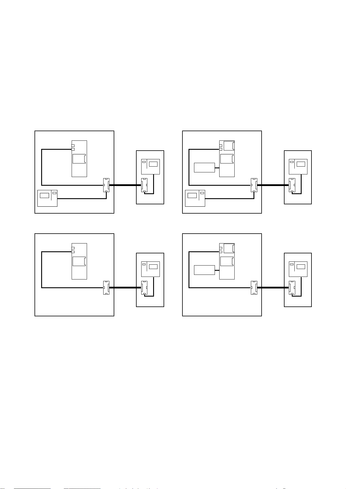
CONFIGURAZIONE CON BOARD "A" E "B" E TERMINALE A BORDO MACCHINA
Questo tipo di configurazione è necessaria per le unità
equipaggiate con due compressori e doppio circuito frigorifero.
A richiesta per tutte le altre tipologie di unità:
- Condizionatori alimentati con acqua refrigerata
- Condizionatori equipaggiati con un compressore
- Condizionatori equipaggiati con due compressori su
unico circuito frigorifero.
Il sistema MP2000 comprende le schede BOARD "A" e "B",
entrambe con la scheda "ADDR" ed il TERMINALE.
Con questa configurazione il sistema controlla totalmente
l'unità e visualizza sul display tutti gli stati di funzionamento
e gli eventuali allarmi intervenuti.
Per il corretto funzionamento del sistema è necessario
impostare i codici di indirizzamento, indicati tra parentesi
nella figura, sui dip-switch di ogni scheda:
- BOARD "A" codice "2"
- BOARD "B" codice "3"
- TERMINALE codice "1"
La remotizzazione degli allarmi è possibile tramite due relè
di Allarme Generale programmabili con contatto pulito
presenti sulla BOARD "A" e tramite specifici relè con
contatto pulito presenti sulla BOARD "B".
A richiesta:
- Porta seriale "RS485" solo per BOARD "A"
- Scheda "ADDR+CK" solo per BOARD "A"
- Scheda "Umidificatore"
CONFIGURATION WITH BOARD "A" AND "B" AND
TERMINAL ON UNIT
This configuration is suitable for units equipped with two
compressors working on two gas circuit.
This configuration is available on request for all other units:
- Air conditioners with chilled water feeding,
- Air conditioners equipped with one compressor,
- Air conditioners equipped with two compressors working
on a single gas circuit.
The MP2000 microprocessor control system includes
BOARD "A" and "B", both with "ADDR" board and TERMINAL.
In this configuration the system controls the unit showing
on the display all the unit working status and the eventual
intervened alarms.
For a correct system operation it is necessary to set the
address code, between brackets in the picture, on dipswitch of each board.
- BOARD "A" code "2"
- BOARD "B" code "2"
- TERMINAL code "1"
The alarms remotization is possible through two General
Alarm relays with voltage free contact on BOARD "A" and
through specific relays with voltage free contacts on BOARD
"B".
On request:
- Serial port "RS485" - only for BOARD "A"
- Board "ADDR+CK" - only for BOARD "A"
- Board "Humidifier"
STANDARD
ADDR
BOARD
B
(3)
(1)
TERMINAL
ADDR
BOARD
A
(2)
CONDIZIONATORE
AIR CONDITIONER
Fig. 14
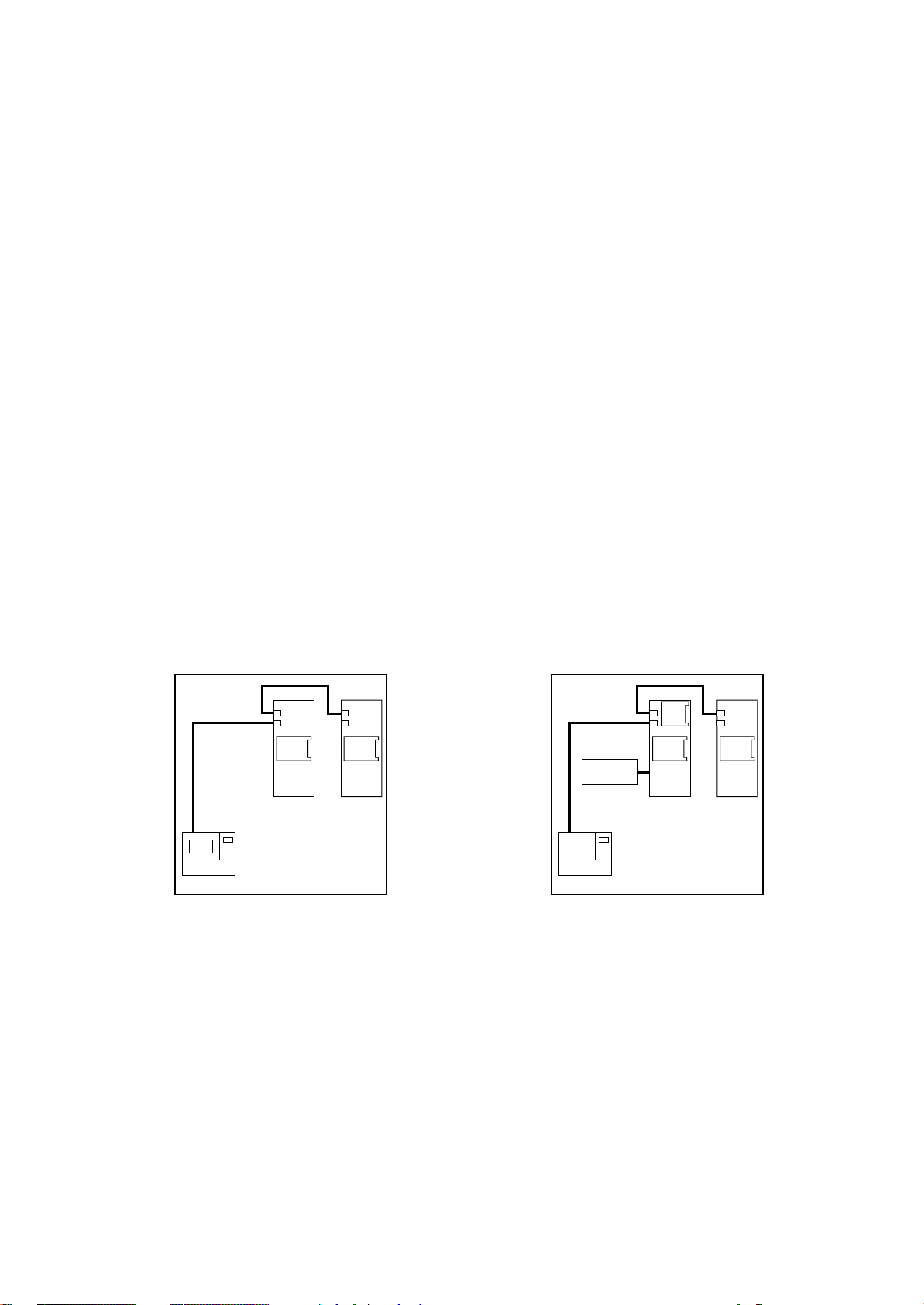
CONFIGURAZIONE CON BOARD "A" E "B" E TERMINALE A BORDO MACCHINA E/O REMOTO "T"
Questa configurazione presenta le stesse caratteristiche
della precedente ma consente la gestione dell'unità anche
dal TERMINALE REMOTO "T".
Per il corretto funzionamento del sistema è necessario
impostare i codici di indirizzamento, indicati tra parentesi
nella figura, sui dip-switch di ogni scheda:
- BOARD "A" codice "2"
- BOARD "B" codice "3"
- TERMINALE codice "1"
- TERMINALE REMOTO codice "15"
La remotizzazione degli allarmi è possibile tramite due relè
di Allarme Generale programmabili con contatto pulito
presenti sulla BOARD "A" e tramite specifici relè con
contatto pulito presenti sulla BOARD "B".
OPTIONAL
RS
485
Umidif.
Humidif.
(1)
TERMINAL
CK
ADDR
BOARD
A
(2)
CONDIZIONATORE
AIR CONDITIONER
ADDR
BOARD
B
(3)
CONFIGURATION WITH BOARD "A" AND "B" AND
TERMINAL ON UNIT AND/OR "T" REMOTE
This configuration has the same characteristics of the
previous one, but allows the unit management also from
the "T" REMOTE TERMINAL.
For a correct system operation it is necessary to set the
address code, between brackets in the picture, on dipswitch of each board.
- BOARD "A" code "2"
- BOARD "B" code "3"
- TERMINAL code "1"
- REMOTE TERMINAL code "15"
The alarms remotization is possible through two General
Alarm relays with voltage free contact on BOARD "A" and
through specific relays with voltage free contacts on BOARD
"B".
RC GROUP - 149_ItEn.0102
19
Page 20
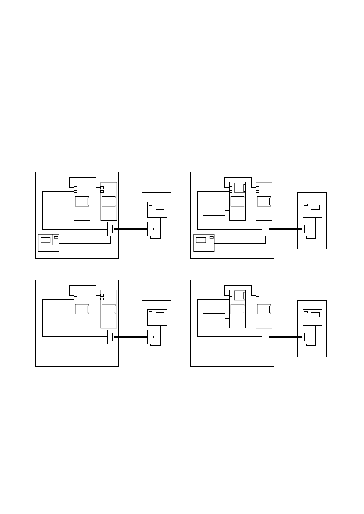
MP2000 AIR CONDITIONERS
Sistema di controllo a microprocessore per condizionatori d'aria •
Air conditioners microprocessor control system
La scheda "T" del condizionatore è fornita non installata in
quanto, in caso di rete LAN, deve essere posizionata
sull'unità più vicina al TERMINALE REMOTO "T".
Il TERMINALE remoto e la seconda scheda "T" sono
installati nel box di contenimento per installazione a parete.
Il cavo di collegamento tra le due schede "T" è a cura del
Cliente (max 200m).
A richiesta:
- Porta seriale "RS485" - solo per BOARD "A"
- Scheda "ADDR+CK" - solo per BOARD "A"
- Scheda "Umidificatore"
- Detrazione TERMINALE - unità priva di TERMINALE e
controllata dal TERMINALE REMOTO "T".
STANDARD OPTIONAL
Terminale remoto "T"
"T" Remote terminal
TERMINAL
(15)
Scheda T
T board
(1)
TERMINAL
ADDR
BOARD
A
(2)
ADDR
BOARD
(3)
Scheda T
T board
B
CONDIZIONATORE
AIR CONDITIONER
The air conditioner "T" board is supplied not installed
because, in case of LAN network, it has to be positioned on
the unit closest to the "T" REMOTE TERMINAL.
The remote TERMINAL and the second "T" board are
installed in the wall mounting box.
The connection cable between the two "T" boards is by
Customer care (200m max).
On request:
- Serial port "RS485" - only for BOARD "A"
- Board "ADDR+CK" - only for BOARD "A"
- Board "Humidifier"
- TERMINAL removal - unit without TERMINAL and controlled only by "T" REMOTE TERMINAL.
Terminale remoto "T"
"T" Remote terminal
TERMINAL
(15)
Scheda T
T board
Umidif.
Humidif.
(1)
TERMINAL
RS
485
CK
ADDR
BOARD
A
(2)
ADDR
BOARD
(3)
Scheda T
T board
B
CONDIZIONATORE
AIR CONDITIONER
OPTIONAL OPTIONAL
(3)
Scheda T
T board
ADDR
BOARD
B
ADDR
BOARD
A
(2)
CONDIZIONATORE
AIR CONDITIONER
Terminale remoto "T"
"T" Remote terminal
TERMINAL
(15)
Scheda T
T board
Umidif.
Humidif.
RS
485
CK
ADDR
BOARD
A
(2)
CONDIZIONATORE
AIR CONDITIONER
Fig. 15
ADDR
BOARD
(3)
Scheda T
T board
Terminale remoto "T"
"T" Remote terminal
TERMINAL
B
(15)
Scheda T
T board
20
RC GROUP - 149_ItEn.0102
Page 21
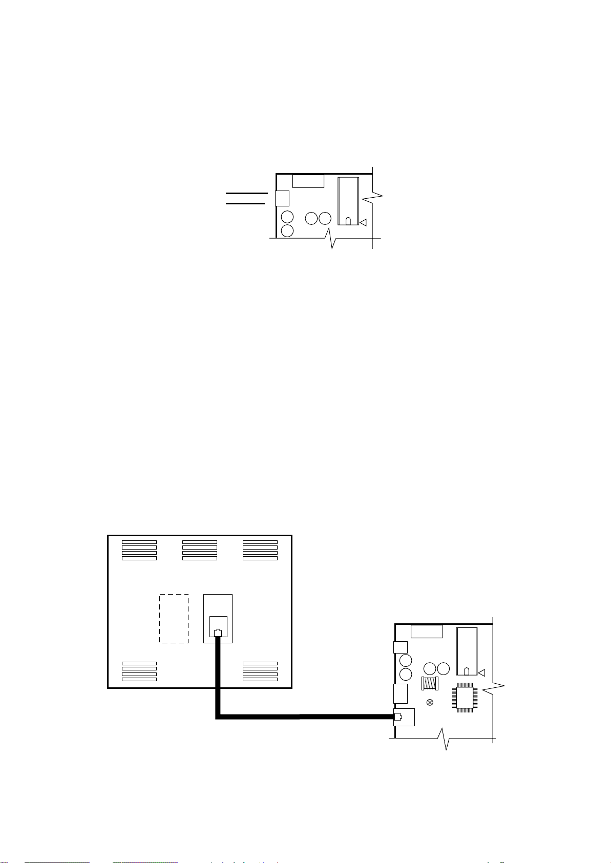
MP2000 AIR CONDITIONERS
Sistema di controllo a microprocessore per condizionatori d'aria •
Air conditioners microprocessor control system
CONNESSIONI ELETTRICHE
ALIMENTAZIONE ELETTRICA
24Vac o 24Vdc (+10% -15%) 50/60 Hz tramite trasformatore.
15VA per alimentazione di ogni scheda BOARD.
1,5VA per alimentazione ingressi digitali ID.
G
24V
CONNESSIONE TRA TERMINALE A BORDO MACCHINA E SCHEDA BOARD "A"
La connessione tra il TERMINALE e la scheda BOARD
"A" viene effettuata tramite cavo telefonico a 6 vie fornito
con l'unità.
Per effettuare il collegamento basta inserire il connettore
telefonico nel morsetto J19 della scheda BOARD "A" e nel
connettore del TERMINALE .
Inserire a fondo il connettore fino ad avvertire lo scatto del
serraggio. Per estrarre il connettore basta premere leggermente sul fermo in plastica sporgente e sfilare il cavo.
La connessione consente l'alimentazione elettrica del TERMINALE (30Vdc) e la trasmissione dati.
La scheda BOARD "A" può funzionare anche senza TERMINALE.
Non scollegare e poi ricollegare il TERMINALE alla
BOARD "A" senza aver atteso circa 5 secondi (qualora
l’operazione venga eseguita a macchina accesa).
J17
G0
Fig. 16
ELECTRIC CONNECTIONS
ELECTRIC FEEDING
24Vac or 24Vdc (+10% -15%) 50/60 Hz through transformer.
15VA for each BOARD feeding.
1,5VA for digital ID inlets feeding.
FUSE
1
CONNECTION BETWEEN TERMINAL ON UNIT AND
BOARD "A"
The connection between TERMINAL and BOARD "A" is
performed by means of a 6-way telephone-type cable
supplied with the unit.
The connection is carried out by plugging the telephone
connector into the connector J19 of the BOARD "A" and
into the connector B of the TERMINAL.
Plug the connector until a click is heard.
To unplug the connector, push gently the prominent plastic
tab and remove the cable.
The connection allows the TERMINAL electrical feeding
(30Vdc) and data transmission.
The BOARD "A" can operate also in absence of terminal
unit.
Anyway, when the system is ON, allow at least 5
seconds between disconnection and following connection of the two units.
VISTA POSTERIORE TERMINALE
TERMINAL BACK VIEW
Fig. 17
MAX 3m
J17
J11
FUSE
1
J19
RC GROUP - 149_ItEn.0102
21
Page 22
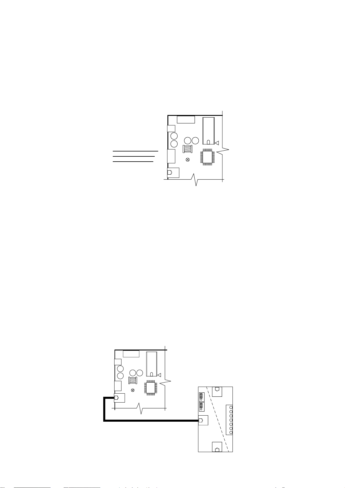
MP2000 AIR CONDITIONERS
Sistema di controllo a microprocessore per condizionatori d'aria •
Air conditioners microprocessor control system
CONNESSIONE TRA BOARD "A" E BOARD "B"
La connessione tra la scheda BOARD "A" e la scheda
BOARD "B" è realizzata in fabbrica con cavo tripolare sui
connettori J11.
La connessione consente lo scambio di informazioni tra le
2 schede.
Per questo tipo di collegamento è utilizzato un cavo elettri-
2
co con sezione di 0,5 mm
.
Non utilizzare il connettore per la connessione seriale.
GND
RX/TX-
RX/TX+
Fig. 18
CONNESSIONE TRA BOARD "A" E TERMINALE REMOTO "T" (max 200m)
La connessione tra la scheda BOARD "A" ed il TERMINALE REMOTO "T" consente l'alimentazione elettrica del
terminale remoto (30Vdc) e lo scambio di informazioni.
La scheda "T" del condizionatore è fornita non installata in
quanto, in caso di collegamento LAN, deve essere posizionata sull'unità più vicina al TERMINALE REMOTO "T".
La connessione interna all'unità tra BOARD "A" e scheda
"T" è da realizzarsi in cantiere con cavo telefonico a 6 vie
(Cavo fornito con "kit Terminale Remoto "T"). E' necessario
predisporre i ponticelli J14 - J15 della scheda "T" in posizione 1-2 per rendere l'alimentazione elettrica diponibile su
tutti i connettori (A-B-C-M).
Inserire a fondo il connettore fino ad avvertire lo scatto del
serraggio. Per estrarre il connettore basta premere leggermente sul fermo in plastica sporgente e sfilare il cavo.
Non scollegare e poi ricollegare il TERMINALE alla
BOARD "A" senza aver atteso circa 5 secondi (qualora
l’operazione venga eseguita a macchina accesa).
CONNECTION BETWEEN BOARD "A" AND BOARD "B"
The connection between BOARD "A" and BOARD "B" is
performed in factory with a three-pole cable on connector
J11.
The connection allows communication exchange between
the 2 cards.
For this connection an electric cable with section of 0,5mm
is utilized.
Don't use the connector for serial connection.
FUSE
1
J17
J11
J19
CONNECTION BETWEEN BOARD "A" AND "T" REMOTE TERMINAL (max 200m)
The connection between BOARD "A" and "T" REMOTE
TERMINAL allows the remote terminal electrical feeding
(30Vdc) and communication exchange.
The air conditioner "T" board is supplied not installed
because, in case of LAN network, it has to be positioned on
the unit closest to the "T" REMOTE TERMINAL.
The connection between BOARD "A" and "T" board has to
be effectuated with a 6-way telephone-type cable (the
cable is supplied with "T Remote Terminal kit"). It is
necessary to set the J14-J15 jumpers of the "T" card on 12 position. In this way the electrical feeding is available on
all connectors (A-B-C-M).
Plug the connector throughly until a click is heard.
To unplug the connector, push gently the prominent plastic
tab and remove the cable.
Anyway, when the system is ON, allow at least 5
seconds between disconnection and following connection of the two units.
2
22
GND
RX/TX-
RX/TX+
FUSE
1
G
J17
G0
J11
J19
J14
A
J15
BM
6
5
4
3
2
1
0
C
Fig. 19
RC GROUP - 149_ItEn.0102
Page 23

MP2000 AIR CONDITIONERS
Sistema di controllo a microprocessore per condizionatori d'aria •
Air conditioners microprocessor control system
La connessione tra scheda "T" a bordo macchina e scheda
"T" del TERMINALE REMOTO "T" è a cura del Cliente.
Per questo tipo di collegamento utilizzare un cavo scher-
2
mato a 3 coppie intrecciate con sezione di 0,5 mm
(tipo
AWG20) per una lunghezza massima complessiva di 200m.
Lo schermo del cavo deve essere collegato sul morsetto
"0" della scheda "T".
J14
1
2
3
1
2
3
J15
BM
A
6
5
4
3
2
1
0
+VRL = 30Vdc
GND
Rx+ / Tx+
Rx– / Tx–
GND
+VRL = 30Vdc
C
The connection between the unit "T" card and the "T" card
of the "T" REMOTE TERMINAL is by Customer care.
For this connection please use a three twisted-pair shielded
2
cable with section of 0,5mm
(type AWG20) with max
length of 200m.
The shield must be connected to the "0" terminal of the "T"
card.
COPPIA 1 -
COPPIA 2 -
COPPIA 3 -
CALZA -
SHIELD
PAIR 1
PAIR 2
PAIR 3
Fig. 20
La connessione tra la scheda "T" del TERMINALE REMOTO "T" ed il relativo TERMINALE è realizzata con cavo
telefonico a 6 vie (Cavo fornito con kit "Terminale Remoto"). E' necessario predisporre i ponticelli J14 - J15 della
scheda "T" in posizione 1-2 per rendere l'alimentazione
elettrica diponibile su tutti i connettori (A-B-C-M).
Inserire a fondo il connettore fino ad avvertire lo scatto del
serraggio.
Per estrarre il connettore basta premere leggermente sul
fermo in plastica sporgente e sfilare il cavo.
VISTA POSTERIORE TERMINALE REMOTO "T"
"T" REMOTE TERMINAL BACK VIEW
J14
J15
The connection between "T" card and "T" REMOTE TERMINAL is performed by means of a 6-way telephone-type
cable (the cable is supplied with "Remote Terminal" kit).
It is necessary to set the J14-J15 jumpers of the "T" card on
1-2 position. In this way the electrical feeding is available on
all connectors (A-B-C-M).
Plug the connector throughly until a click is heard.
To unplug the connector, push gently the prominent plastic
tab and remove the cable.
A
6
5
4
BM
3
2
1
0
+VRL = 30Vdc
GND
Rx+ / Tx+
Rx– / Tx–
GND
+VRL = 30Vdc
COPPIA 1
PAIR 1
COPPIA 2
PAIR 2
COPPIA 3
PAIR 3
RC GROUP - 149_ItEn.0102
C
Fig. 21
23
Page 24
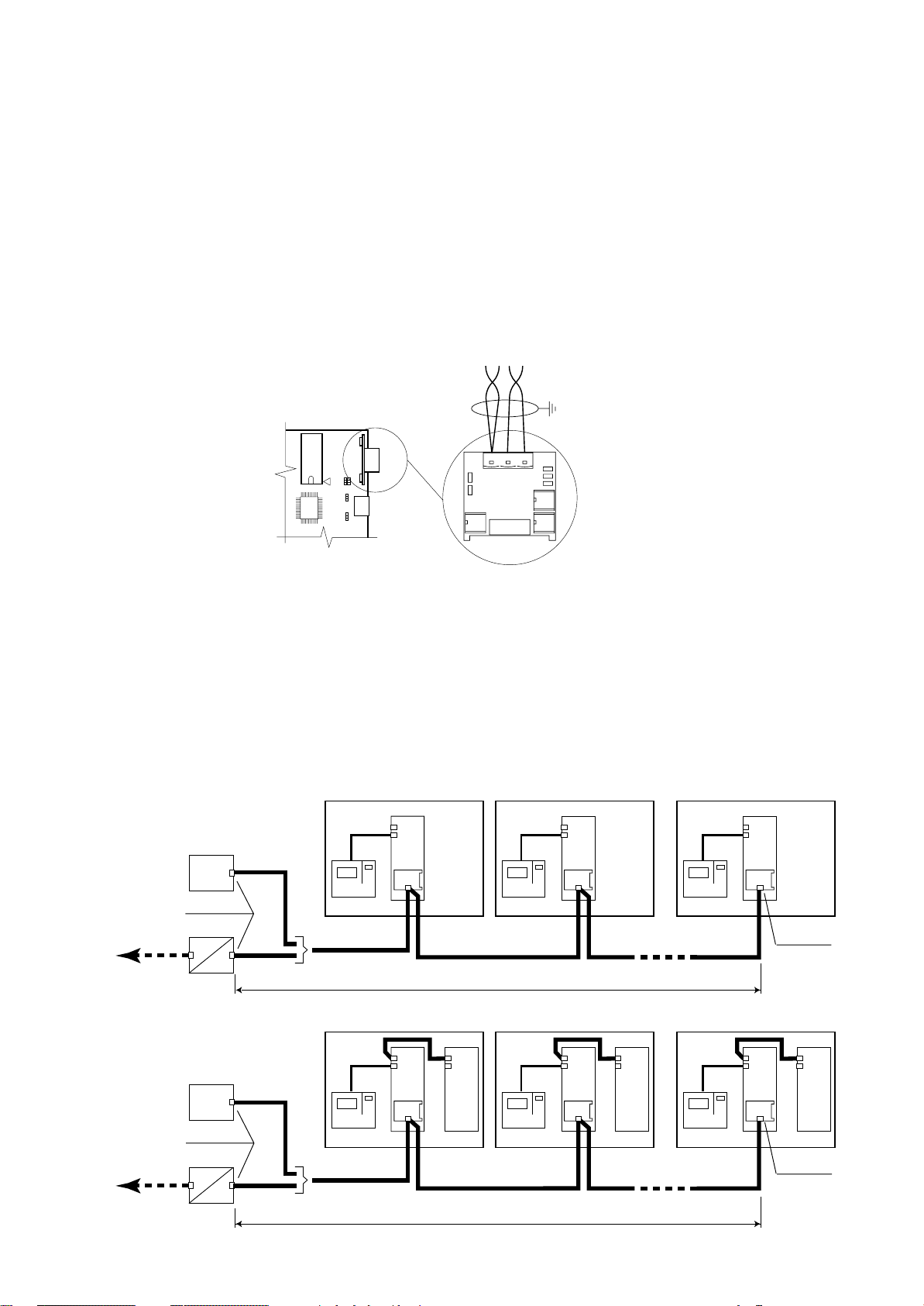
MP2000 AIR CONDITIONERS
Sistema di controllo a microprocessore per condizionatori d'aria •
Air conditioners microprocessor control system
CONNESSIONE SERIALE RS485
La connessione è a cura del Cliente.
La connessione RS485 deve essere realizzata secondo
le normative ISO/IEC 8482 - 1993 (Information Technology
- Telecommunication and information exchange between
systems - Twisted-pair multipoint interconnections).
La scheda è installata sulla BOARD "A" e per questo tipo
di collegamento utilizzare un cavo schermato a 2 coppie
intrecciate con sezione di 0,22 mm
2
(tipo AWG24). Una
sola estremità dello schermo del cavo deve essere collegata a terra.
RC GROUP declina ogni responsabilità per una non
corretta esecuzione del collegamento.
COPPIA 1
RS485
J9 J8
J29
J1
J28
Fig. 22
SERIAL CONNECTION RS485
Connection is by Customer care.
The RS485 connection must be performed according to
ISO/IEC 8482 - 1993 (Information Technology - Telecommunication and information exchange between systems Twisted-pair multipoint interconnections).
This board is installed on BOARD "A" and for this connection please use a two twisted-pair shielded cable with
section of 0,22mm
2
(type AWG24).
Only one shielded-end must be connected to ground.
RC GROUP is not responsible for any wrong connection.
GND RX+
TX+
COPPIA 2
PAIR 2
RXTX-
PAIR 1
Collegamento seriale con protocollo di comunicazione "RC-com" per massimo 32 unità collegate in multipunto.
- Collegamento diretto:
La linea seriale RS485 è collegata direttamente ad un
sistema di supervisione locale.
- Collegamento con GATEWAY-MODEM:
Il collegamento prevede la connessione via modem ad
un supervisore remoto.
Estensione complessiva massima della linea seriale 1.200m.
SISTEMA SUPERVISIONE
SUPERVISION SYSTEM
RS232
GATEWAY - MODEM
RC-com protocol
Protocollo RC-com
SISTEMA SUPERVISIONE
SUPERVISION SYSTEM
Inizio linea
Start line
RS485
RS485
RS485
UNITA' 1 •
TERMINAL
Protocollo RC-com
RC-com protocol
UNITA' 1 •
UNIT 1
BOARD
A
UNIT 1
BOARD
A
Serial connection with "RC-com" communication protocol for max 32 units in multipoint connection.
- Direct connection:
The RS485 serial line is directly connected to a local
supervision system.
- Connection with GATEWAY-MODEM:
Connection via modem to a remote supervision system.
Max length of the serial line 1.200m.
UNITA' 32 •
TERMINAL
UNITA' 32 •
RS485
MAX 1.200m
BOARD
B
UNITA' 2 •
TERMINAL
UNITA' 2 •
UNIT 2
BOARD
A
RS485
MAX 32 UNITA'
MAX 32 UNITS
UNIT 2
BOARDABOARD
B
UNIT 32
BOARD
A
UNIT 32
BOARD
A
RS485
Fine linea
End line
BOARD
B
RC-com protocol
Protocollo RC-com
24
Inizio linea
Start line
RS232
GATEWAY - MODEM
RS485
TERMINAL
Protocollo RC-com
RC-com protocol
Fig. 23
RS485
MAX 1.200m
TERMINAL
RS485
TERMINAL
MAX 32 UNITA'
MAX 32 UNITS
RC GROUP - 149_ItEn.0102
RS485
Fine linea
End line
Page 25
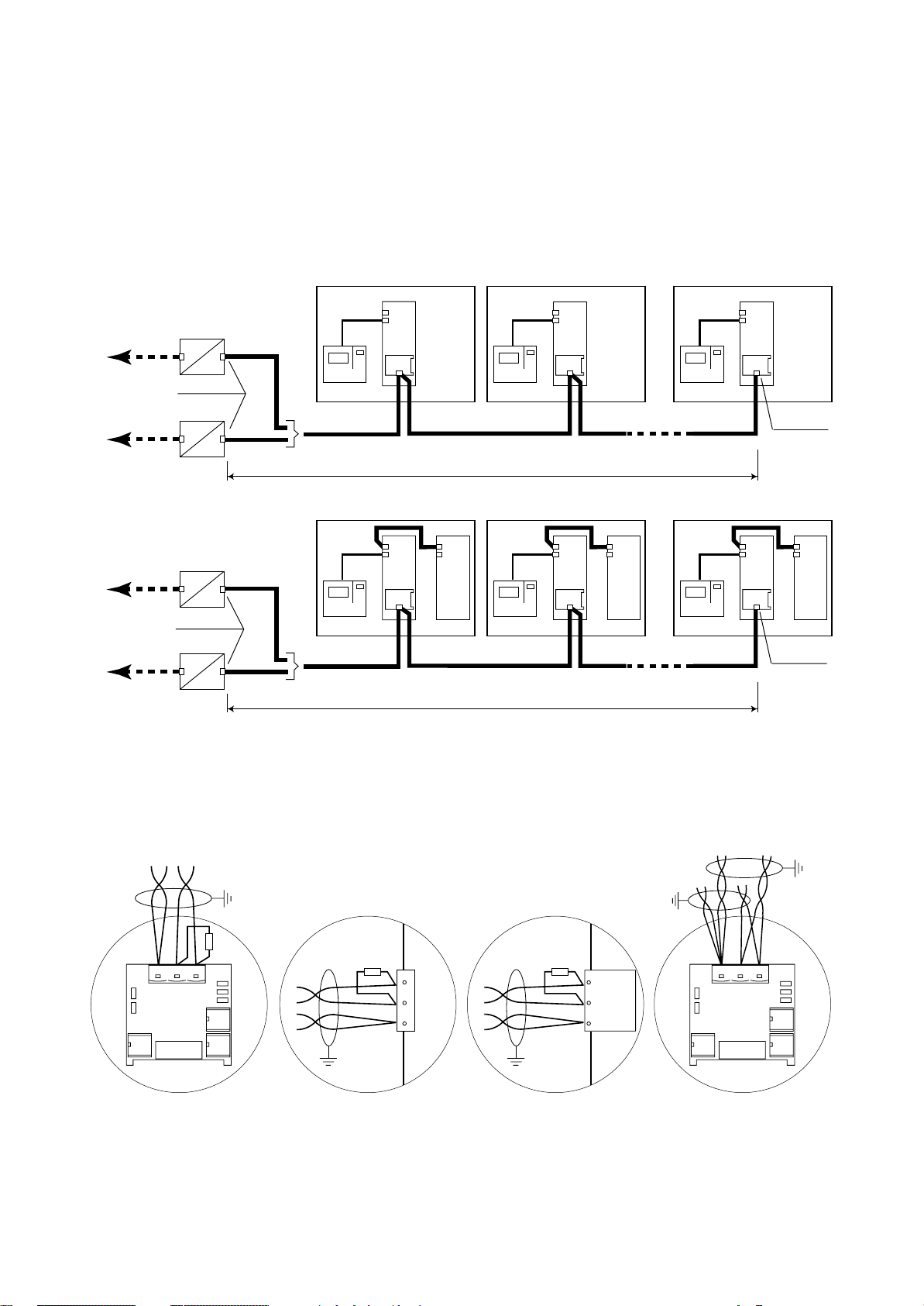
MP2000 AIR CONDITIONERS
Sistema di controllo a microprocessore per condizionatori d'aria •
Air conditioners microprocessor control system
Collegamento seriale con protocollo di comunicazione MODBUS - JBUS per massimo 16 unità collegate in
multipunto.
Collegamento con GATEWAY-MODBUS per la traduzione
del protocollo RC-Com in MODBUS/JBUS e connessione
ad un supervisore locale.
Estensione complessiva massima della linea seriale 1.200m.
GATEWAY - MODBUS
RS485
RS232
MODBUS/JBUS protocol
Protocollo MODBUS/JBUS
GATEWAY - MODBUS
GATEWAY - MODBUS
RS485
Inizio linea
Start line
RS485
RS485
RS485
UNITA' 1 •
TERMINAL
Protocollo RC-com
RC-com protocol
UNITA' 1 •
UNIT 1
BOARD
A
UNIT 1
BOARD
A
RS485
MAX 1.200m
BOARD
B
Serial connection with MODBUS - JBUS communication protocol for max 16 units in multipoint connection.
Connection with GATEWAY-MODBUS for RC-com protocol translation into MODBUS/JBUS protocol and connection to a local supervision system.
Max length of the serial line 1.200m.
UNITA' 2 •
TERMINAL
UNITA' 2 •
UNIT 2
BOARD
A
UNIT 2
BOARD
A
RS485
MAX 16 UNITA'
MAX 16 UNITS
BOARD
B
UNITA' 16 •
TERMINAL
UNITA' 16 •
UNIT 16
BOARD
A
UNIT 16
BOARD
A
RS485
Fine linea
End line
BOARD
B
RS232
MODBUS/JBUS protocol
Protocollo MODBUS/JBUS
GATEWAY - MODBUS
Inizio linea
Start line
RS485
TERMINAL
Protocollo RC-com
RC-com protocol
Fig. 24
Connessione tra MP2000 e GATEWAY
Connessione tra MP2000 e SUPERVISORE
Per la connessione è necessario prevedere una resistenza
terminale di 120Ω all'inizio ed alla fine della linea.
COPPIA 1
PAIR 1
GND RX+
TX+
COPPIA 2
PAIR 2
RXTX-
120Ω
120Ω
RX-
5
TX-
4
RX+
TX+
1
GND
RS485
MAX 1.200m
TERMINAL
RS485
TERMINAL
MAX 16 UNITA'
MAX 16 UNITS
RS485
Fine linea
End line
Connection between MP2000 and GATEWAY
Connection between MP2000 and SUPERVISOR
Ω
For the connections it is necessary to install a 120
terminal
resistance at the beginning and at the end of the line.
120Ω
RX- / TX-
RX+ / TX+
GND
GND RX+
TX+
RXTX-
Connessione di fine linea
Connection of end line
Connessione Gateway (inizio linea)
Gateway connection (start line)
Fig. 25
Per il GATEWAY e le relative connessioni fare riferimento
al relativo manuale di istruzione.
RC GROUP - 149_ItEn.0102
Connessione Supervisore (inizio linea)
Supervisor connection (start line)
Come doppiare i cavi
How to twin the cables
For the GATEWAY connections please refer to the relative
instruction manual.
25
Page 26
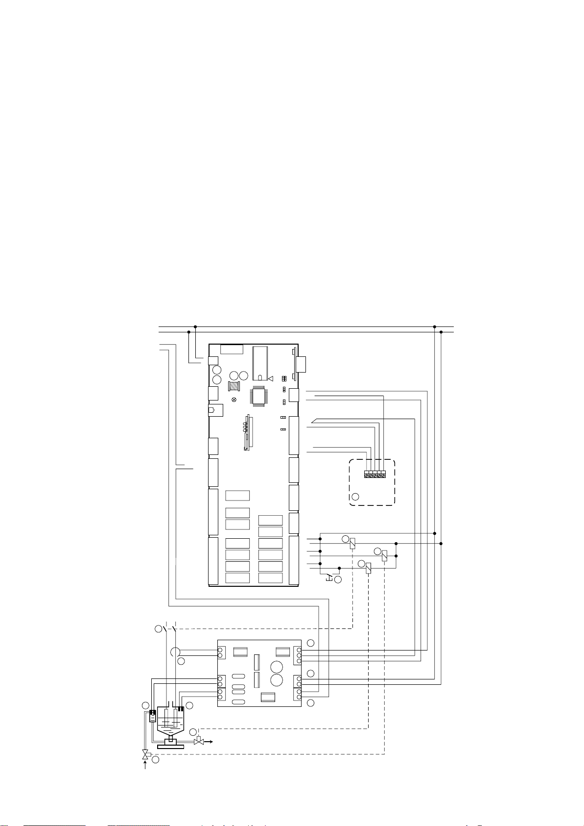
MP2000 AIR CONDITIONERS
Sistema di controllo a microprocessore per condizionatori d'aria •
Air conditioners microprocessor control system
CONNESSIONE SISTEMA DI UMIDIFICAZIONE
Il sistema di umidificazione prevede i seguenti collegamenti:
1 Collegamento della sonda combinata di temperatura/
umidità alla BOARD "A".
2 Collegamento alimentazione elettrica della scheda
umidificatore.
3 Collegamento trasformatore amperometrico di corrente
umidificatore alla scheda umidificatore.
4 Collegamento sensore di conducibilità acqua alla
scheda umidificatore.
5 Collegamento sensore di livello acqua alla scheda
umidificatore.
6 Collegamento uscita digitale livello acqua dalla scheda
umidificatore alla scheda BOARD "A" (24Vac).
7 Collegamento uscite analogiche di conducibilità acqua
e corrente umidificatore dalla scheda umidificatore alla
scheda BOARD "A".
8 Pulsante per scarico acqua manuale.
9 Relè per comando scarico acqua.
10 Relè per comando carico acqua.
11 Teleruttore umidificatore.
24V
24V
RX/TX-
RX/TX+
ID11-230Vac
ID11-24Vac
ID11-R
----------ID12-R
ID12-24Vac
ID12-230Vac
NO11
NC11
NO10
NC10
NO13
GND
VG0
VG1
------
-----NO9
NC9
NO8
-----NO7
-----NO6
------
FUSE
1
G
J17
G0
J11
J19
1
J20
Y1
Y0
1
J21
1
C11
J22
C10
C9
1
C8
C7
J24
C6
C13
K11
K10
K13
J14 = 2-3
J28 = 2-3
J29 = 2-3
K9
K8
K7
K6
K1
K2
K3
K4
K5
K12
J9 J8
J29
J28
HUMIDIFICATION SYSTEM CONNECTION
The humidification system needs the following connections:
1 Connection of the combined temperature/humidity sen-
sor to BOARD "A".
2 Connection of the electric feeding for the humidifier
card.
3 Connection of the humidifier amperometric transformer
to the humidifier card.
4 Connection of the water conductivity sensor to the
humidifier card.
5 Connection of the water level sensor to the humidifier
card.
6 Connection of the water level digital output from hu-
midifier card to BOARD "A" (24Vac).
7 Connection of the water conductivity and humidifier
current analog outputs from humidifier card to BOARD
"A".
8 Push button for manual water drain
9 Relay for water drain
10 Relay for water fill
11 Humidifier contactor
RS485
3
3
2
2
1
1
3
2
1
B8
J1
+24Vdc
B7
3
1
2
1
J15
321
B6
AVSS
J14
B5
321
B4
AVSS
J2
B3
B2
AVSS
B1
1
IDCM2
ID10
ID9
J3
ID8
ID7
1
ID6
IDCM1
ID5
ID4
J4
ID3
ID2
ID1
1
C1
NO1
------
J5
C2
NO2
1
C3
NO3
-----C4
NO4
------
J6
C5
NO5
-----C12
NO12
1
11
8
M
+ (G)
H (%rH)
NTC (°C)
NTC (°C)
1
10
9
26
230/400V
11
3
4 5
10
J3
T1
T2
J2
C1
C2
L1
L2
J1
J6
7
B8
G0
B7
J5
2
G
G0
O1
O2
J4
6
9
Fig. 26
RC GROUP - 149_ItEn.0102
Page 27
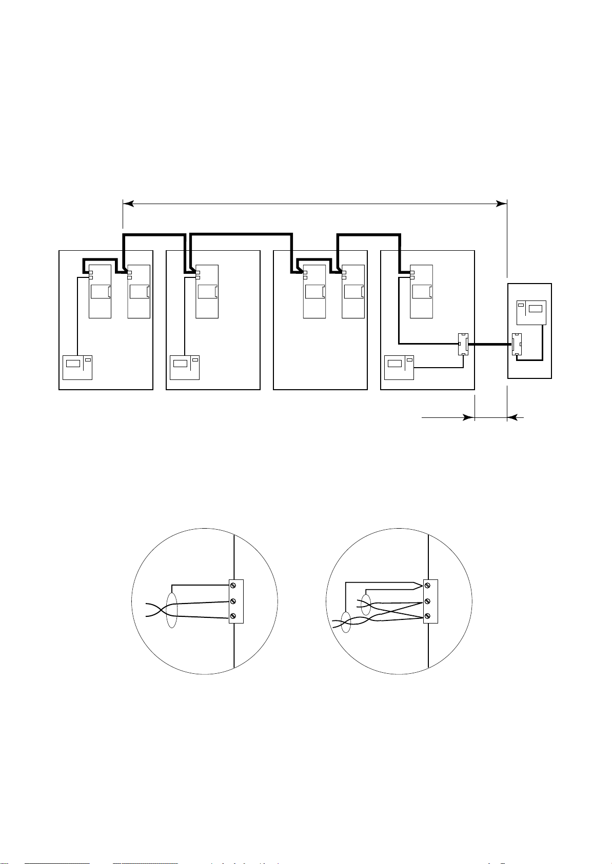
MP2000 AIR CONDITIONERS
Sistema di controllo a microprocessore per condizionatori d'aria •
Air conditioners microprocessor control system
CONNESSIONE RETE LAN
La connessione è a cura del Cliente.
Per questo tipo di collegamento utilizzare un cavo scher-
2
mato ad 1 coppia intrecciata con sezione di 0,5 mm
(tipo
AWG20) da collegarsi al morsetto J11 della scheda BOARD.
ATTENZIONE! Rispettare la polarità; l'RX/TX+ della
scheda deve essere collegato al rispettivo RX/TX+ della
successiva e così anche per l'RX/TX-.
ADDR ADDR ADDR ADDR ADDR
BOARD
UNIT 1
B
BOARD
A
TERMINAL TERMINAL
UNITA' 2 •
UNIT 2
BOARD
TERMINAL
UNITA' 1 •
ADDR
A
LAN CONNECTION
Connection is by Customer care.
For this connection please use a single twisted-pair shielded
cable with section of 0,5mm
cable to the J11 terminal of the BOARD card.
ATTENTION to the polarity; the RX/TX+ of the BOARD
must be connected to the RX/TX+ of the next one and so
on for the RX/TX-.
MAX 500m
BOARDABOARD
UNITA' 3 •
UNIT 3
2
(type AWG20). Connect the
"T" REMOTE
B
BOARD
A
UNITA' 4 •
MAX 200m
T
UNIT 4
TERMINAL
T
Fig. 27
La figura indica una configurazione tipo completa di Terminale Remoto "T" che può anche non essere presente nella
rete LAN.
J11
GND
RX/TX-
RX/TX+
Connessione della scheda
Card connection
Fig. 28
RC GROUP declina ogni responsabilità per una non
corretta esecuzione del collegamento.
In the picture is show a complete configuration with "T"
Remote Terminal that can not be present in a LAN network.
J11
GND
RX/TX-
RX/TX+
Come doppiare i cavi
How to twin the cables
RC GROUP is not responsible for any wrong connection.
RC GROUP - 149_ItEn.0102
27
Page 28
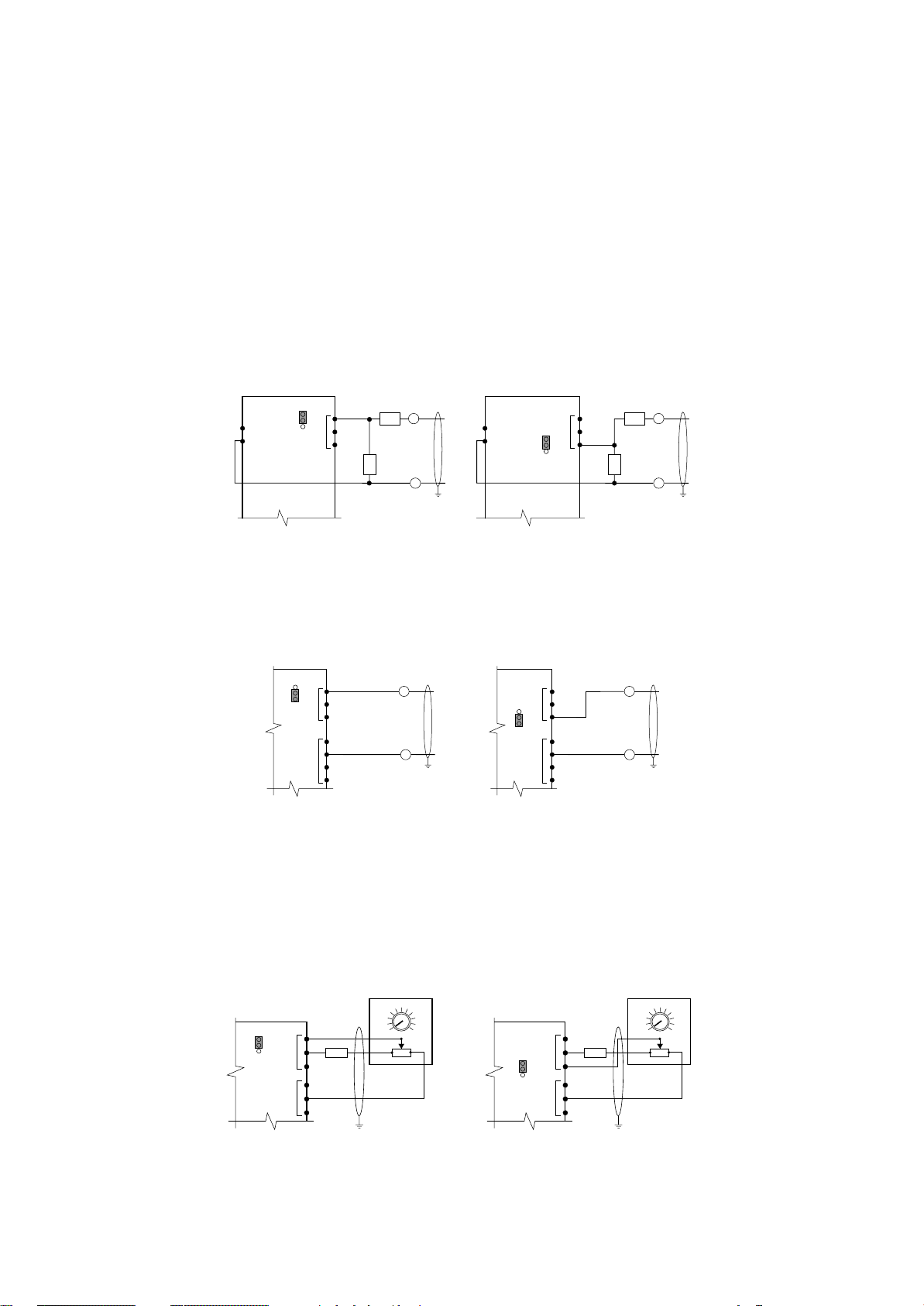
MP2000 AIR CONDITIONERS
Sistema di controllo a microprocessore per condizionatori d'aria •
Air conditioners microprocessor control system
COLLEGAMENTO PER SISTEMA DI COMPENSAZIONE SET POINT TEMPERATURA
La connessione è a cura del Cliente; utilizzare un cavo
schermato ad 1 coppia intrecciata con sezione di 0,5 mm
(tipo AWG20).
Collegamento per sistema di compensazione set point
temperatura automatico (segnale in tensione).
Il segnale di compensazione proviene da un sistema esterno (sonde attive o sistema di supervisione) e può essere
collegato a più unità contemporaneamente.
In base al segnale installare le resistenze da 0,5÷1W, non
fornite, come indicato in figura e predisporre il ponticello
J28 per l'ingresso B7 o il ponticello J29 per l'ingresso B8.
Segnale R1 R2
÷1V -- --
0
0÷5V 330Ω 1300Ω
÷10V 330Ω 3000Ω
0
0÷20V 330Ω 6200Ω
BOARD
G
G0
J29
B8
3
2
1
J1
+
R2
0÷1V
0÷5V
0÷10V
R1
0÷20V
–
Fig. 29
Collegamento per sistema di compensazione set point
temperatura automatico (segnale in corrente).
Il segnale di compensazione proviene da un sistema esterno (sonde attive o sistema di supervisione) e può essere
collegato ad una sola unità.
BOARD
B8
3
J29
2
1
J1
+
0÷20mA
CONNECTION OF THE TEMPERATURE SET POINT
COMPENSATION SYSTEM
Connection is by Customer care.
2
For this connection please use a single twisted-pair shielded
cable with section of 0,5mm
2
(type AWG20).
Connection for automatic temperature set point compensation (voltage signal).
The compensation signal coming from an external system
(active sensor or supervision system) and it is possible a
multipoint connection with more units.
÷
According to the signal type install two 0,5
1W resistances,
not furnished, as shown in the picture and predisposition of
the J28 jumper, for inlet B7, or J29 jumper for inlet B8.
BOARD
G
G0
J28
J1
3
2
1
R2
B7
0÷1V
0÷5V
0÷10V
R1
0÷20V
Signal R1 R2
+
÷
1V -- --
0
0÷5V 330Ω1300
0÷10V 330Ω3000
–
0÷20V 330Ω6200
Ω
Ω
Ω
Connection for automatic temperature set point compensation (current signal).
The compensation signal coming from an external system
(active sensor or supervision system) and it is possible a
single connection with one units.
BOARD
J1
3
J28
B7
2
1
+
0÷20mA
AVSS
J2
–
Fig. 29a
Collegamento per sistema di compensazione set point
temperatura manuale.
Vengono utilizzati un potenziometro da 1KOhm ed una
resistenza da 23KOhm collegati come indicato.
Predisporre il ponticello J28 per l'ingresso B7 o il ponticello
J29 per l'ingresso B8 su 2-3 per segnale in tensione.
Il sistema prevede il collegamento di un potenziometro per
ogni unità.
Fig. 30
24
25
23
BOARD
J29
3
2
1
B8 (0÷1V)
+V
J1
23KΩ 23KΩ
AVSS
J2
26
27
22
2
1KΩ
3
1
Separare quanto più possibile i cavi dei segnali dai
cavi dei carichi induttivi e di potenza per evitare possibili disturbi elettromagnetici.
RC GROUP declina ogni responsabilità per una non
corretta esecuzione del collegamento.
AVSS
J2
–
Connection for manual temperature set point compensation.
Connect a remote 1KOhm potentiometer and a 23Kohm
resistance as per following wiring diagram.
Set the J28 jumper, for inlet B7, or J29 jumper for inlet B8
on 2-3 for voltage signal.
The system provides the connection of one potentimeter
for each unit.
24
25
23
BOARD
J28
+V
J1
B7 (0÷1V)
3
2
1
AVSS
J2
26
27
22
2
1KΩ
3
1
Separate as much as possible the signal cables from
the inductive load and power cables, to avoid any
electromagnetic noise.
RC GROUP is not responsible for any wrong connection.
28
RC GROUP - 149_ItEn.0102
Page 29
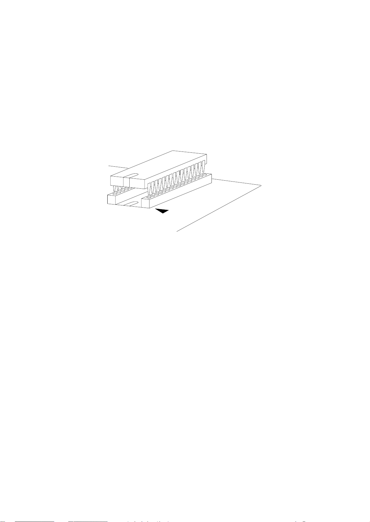
MP2000 AIR CONDITIONERS
Sistema di controllo a microprocessore per condizionatori d'aria •
Air conditioners microprocessor control system
INSERIMENTO DELLA EPROM
Prima di inserire/rimuovere la Eprom togliere l’alimentazione alla scheda.
Per un corretto funzionamento del sistema la Eprom
deve essere inserita nell’apposito zoccolo sulla
BOARD "A" e "B" facendo attenzione che la “tacca”
sulla superficie della Eprom sia nella direzione della
“tacca” di riferimento serigrafata sulla scheda.
Inserire la Eprom sul relativo zoccolo, controllando che
tutti i piedini siano inseriti correttamente nelle loro sedi,
quindi effettuare il MEMORY RESET come indicato nel
relativo capitolo.
INSTALLATION OF THE EPROM
Switch off the system before connecting/disconnecting the Eprom.
When mounting the Eprom into its socket on the
BOARD "A" and "B", pay attention to align the notch on
the surface of the eprom with the corresponding notch
on the socket.
Connect the Eprom into its socket and check that all pins
are correctly inserted, than make the MEMORY RESET as
indicated to the relative chapter.
Fig. 31
Nel rimuovere l’Eprom prestare attenzione a non toccare i
componenti SMD montati sulla scheda nello spazio interno allo zoccolo.
NOTA SU COME MANIPOLARE LE EPROM E LE SCHEDE ELETTRONICHE
I danneggiamenti elettrici che si verificano sui compo-
nenti elettronici avvengono quasi sempre a causa delle
scariche elettrostatiche indotte dall’Operatore.
È quindi necessario adottare adeguati accorgimenti per
queste categorie di componenti, ed in particolare:
• prima di maneggiare qualsiasi componente elettronico o scheda, toccare una messa a terra (una scarica
di 10.000V, tensione molto facile da raggiungere con
l’elettricità statica, produce un arco di circa 1cm).
• i materiali devono rimanere per quanto possibile all’interno delle loro confezioni originali. Utilizzare un imballo antistatico ed evitare di toccare il retro della scheda con le mani.
• evitare nel modo più assoluto di utilizzare sacchetti in
plastica, polistirolo o spugne non antistatiche.
• estrarre dalle confezioni antistatiche originali solo una
Eprom alla volta.
• evitare di toccare con le mani i piedini dell’Eprom, afferrando il componente sulle zone che ne sono prive.
When removing the Eprom do not touch the SMD electronic components mounted on the board in the internal
space of the socket. Don’t touch them with any hardware
tool.
NOTE ON HOW USING THE EPROM AND THE ELECTRONIC CARDS
Electrical damages of the electronic components are
usually due to electrostatic charges induced by the Operator.
It is therefore necessary to pay attention to these components and specially to following:
• before using any electronic component or card, touch a
ground reference (a discharge of 10.000V, very common
due to the static electricity, causes an arc of about 1cm).
• materials should be left as long as possible inside their
original packaging. Handle the boards carefully, without
touching their rear part with the hands.
• do not use plastic bags, polystyrene or non-antistatic
sponges.
• take out of the original antistatic packaging one Eprom at
a time.
• do not touch the pins of the Eprom.
RC GROUP - 149_ItEn.0102
29
Page 30
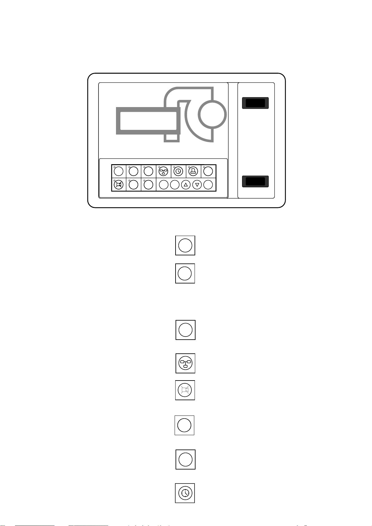
MP2000 AIR CONDITIONERS
Sistema di controllo a microprocessore per condizionatori d'aria •
Air conditioners microprocessor control system
FUNZIONI DELLA TASTIERA E PROGRAMMAZIONE
MP2000
RC GROUP
HOME SET PRG
1
234
MEMO
E
Fig. 32
STATUS
ALARM
567
KEYBOARD FUNCTIONS AND PROGRAMMING
ON/OFF
I ENTER
MAN - O - AUT
SUMMER WINTER
Vengono visualizzate temperatura e umidità ambiente (se presente la sonda), la presenza eventuale di allarmi e lo stato dell’unità.
Visualizzazione del set point di temperatura con
possibilità di variazione. Per variare il set point
premere: tasto ENTER, tasti FRECCIA e tasto
ENTER per conferma dati. Dopo aver inserito
la password e premendo per 3 secondi, è possibile resettare gli allarmi ed attivare la funzione MANUAL.
Dopo aver inserito la password si accede all’elenco dei parametri "SERVICE": set point,
banda di temperatura, pressione, soglie di allarme, allarme generale.
Da un Terminale condiviso permette di accedere ai parametri delle eventuali unità connesse
in rete LAN.
Tacita la suoneria e visualizza l'allarme; premendo un tasto FRECCIA, vengono visualizzati tutti gli allarmi eventualmente presenti.
Vengono visualizzati i valori degli ingressi/uscite analogici e gli stati degli ingressi/uscite digitali. Dopo aver inserito la password, è possibile
calibrare le sonde.
HOME
SET
PRG
ALARM
STATUS
The room temperature and humidity (if the sensor is scheduled), the possible alarms presence
1
and the unit working status are displayed.
The temperature set point is displayed with the
possibility of changing it. To change it press:
2
ENTER key, ARROW key and ENTER key for
data confirmation. After having inserted the password and by pressing for 3 seconds, it is possible to reset the alarms and to activate the
MANUAL function.
After having inserted the password, the list of
"SERVICE" parameters is available: set point,
3
temperature band, pressure, alarm thresholds,
general alarm.
From a shared Terminal, the parameters of the
eventual other units connected in LAN network
4
are displayed.
Switch off buzzer and show the alarm; by pressing an ARROW key the eventual present alarms
5
are displayed.
The analogic inlets/outlets values and the digital
inlets/outlets are displayed. After having inserted
6
the password, it is possible to calibrate the
sensors.
Vengono visualizzati gli ultimi 10 allarmi, le ore
di funzionamento, il numero di avviamenti dei
principali componenti ed è possibile resettare
le ore di funzionamento dei vari contatori.
Permette la visualizzazione/programmazione
dell'orologio datario e la gestione della funzione CHRONO (se presente la scheda CK).
30
MEMO
The last 10 intervened alarms, the working
hours and the number of start-up of the main
7
components are displayed. It is possible to reset
the working hours of the various hourmeters.
By pressing this key, it is possible to display/set
the clock and the CHRONO function managing
(if CK card is present).
RC GROUP - 149_ItEn.0102
Page 31

PRG
3
MP2000 AIR CONDITIONERS
Sistema di controllo a microprocessore per condizionatori d'aria •
Air conditioners microprocessor control system
Non utilizzato.
Accende e spegne il condizionatore.
Non utilizzato.
Solo con funzione "CHRONO" (a richiesta). Attiva l'unità in stand-by .
Scorre le pagine all’interno di ogni menu.
Dal menu principale, premendo uno di questi
tasti, viene visualizzata la versione del programma ed altre funzioni.
Premendo il tasto ENTER, dopo aver inserito
la password, si possono resettare gli allarmi o
attivare manualmente i componenti principali.
Muove il cursore all’interno di una pagina e deve
essere premuto per confermare la modifica di
un parametro.
ON/OFF
E
I
ENTER
Not used.
Switches on and off the unit.
Not used.
Only with "CHRONO" function (on request).
This key activates the unit in stand-by mode.
Runs pages inside each menu.
From main menu, by pressing one of these
keys, the program version and other functions
are displayed.
By pressing ENTER key, after having inserted
the password, the alarm can be reset or the
main components can be set in manual position.
Move the cursor within one page and keep it
pressed to confirm the parameter modification.
Premendo contemporaneamente questi tasti,
dopo aver inserito la password, si accede all’elenco dei parametri "MANUFACTURER".
Premendo contemporaneamente questi tasti si
accede alla maschera di configurazione
HOME
software della rete LAN.
RITORNO ALLA MASCHERA PRINCIPALE
Il ritorno alla maschera principale verrà effettuato nei
seguenti casi:
- premendo il tasto "HOME".
- quando la tastiera non viene premuta per 5 minuti.
- quando è visualizzata la maschera allarmi e gli stessi
scompaiono.
Data ed ora corrente vengono visualizzate se è presente la
scheda indirizzo+orologio "ADDR+CK".
Il valore di umidità ambiente viene visualizzato se è presente la sonda combinata di temperatura/umidità.
13:30 12/02/99
Room temp. 21,5°C
Room humid. 54%rH
Unit ON
HOME
1
By pressing these keys simultaneously, after
having inserted the password, the list of "MANU-
1
FACTURER" parameters is available.
By pressing these keys simultaneously, the
SET
PRG
2
LAN network software configuration mask is
3
displayed.
BACK TO THE MAIN MENU
The display goes back to the main menu in the following
situations:
- by pressing "HOME" key
- when the keyboard is not pressed for 5 minutes.
- when the alarms mask is displayed and the alarms
disappear.
Date and current time are displayed if the address+clock
card "ADDR+CK" is scheduled.
The room humidity value is displayed if the temperature/
humidity sensor is scheduled.
Premendo un tasto FRECCIA viene visualizzata la versione del programma residente nella Eprom.
By pressing an ARROW key the Eprom program version is
displayed.
RC GROUP
CLOSE CONTROL UNITS
Code XXXXXX
Vers. XXXXX 00/00/00
RC GROUP - 149_ItEn.0102
31
Page 32

MP2000 AIR CONDITIONERS
Sistema di controllo a microprocessore per condizionatori d'aria •
Air conditioners microprocessor control system
PARTENZA RANDOM DELL'UNITA'
Quando si attiva appare l'indicazione sul display WAIT
PLEASE - READING INPUTS per circa 1 minuto (random
time).
Il "Random time" è calcolato dal microprocessore per evitare che più unità si attivino nello stesso istante.
Trascorso il "Random time", l'attivazione del ventilatore
principale avviene con un ritardo pari al set "Delay main
fan on".
FUNZIONAMENTO UNITA' (Ventilatore principale)
L'unità si attiva (ventilatore principale On) quando si verificano tutte le seguenti condizioni:
- è stato premuto sulla tastiera il tasto ON/OFF in modo
che il relativo LED sia acceso.
- l'ingresso ON/OFF di abilitazione esterna (ingresso digitale 1) è chiuso.
- il supervisore non ha inviato comandi di spegnimento.
Nel caso in cui il supervisore comandi lo spegnimento
dell'unità è sempre possibile attivare l'unità dal tasto ON/
OFF della tastiera locale.
- non sono presenti condizioni di allarme (sonda di temperatura guasta, termico ventilatore principale, allarme fumofuoco, intervento termostato limite con ripristino manuale.)
Solamente nel caso in cui le condizioni sopra descritte
sono soddisfatte il ventilatore principale può attivarsi unitamente agli altri componenti dell'unità.
RAMDOM STARTING OF THE UNIT
When the unit starts on display appears WAIT PLEASE READING INPUTS for about 1 minute (random time).
The "Random Time" is automatically calculated by the
microprocessor in order to avoid simultaneous units start
up's.
Once "Random time" elapsed, the main fan activation is
delayed by the set "Delay main fan on".
UNIT SWITCH ON (Main fan on)
The unit switches on (main fan on) when the following
conditions happen:
- the keyboard ON/OFF key has been pressed and the
relevant LED is lighting.
- the ON/OFF external enabling input is closed (digital
input 1).
- A switch OFF command has not been sent by the
supervisor.
In case the supervisor switches off the unit, it is still
possible to activate it by pressing the ON key on terminal
keyboard.
- no alarms presence (temperature sensor fault, main fan
thermal protection, smoke-fire alarms, limit thermostat
with manual reset.)
Only if these conditions are satisfy, the main fan starts
together the other unit components.
FUNZIONE CHRONO (a richiesta)
Funzione per l'attivazione dell'unità su fasce orarie.
La funzione prevede l'installazione della scheda ADDR+CK.
Premere il tasto "OROLOGIO" per accede all'impostazione
dell’ora e della data ed ai relativi parametri.
_ Clock & Date
Setting
Time 13:30
Date 12/02/99
Per impostare l’ora premere il tasto "ENTER" e variare il
valore dell’ora con i tasti "FRECCIA", premere di nuovo
"ENTER" per variare il valore dei minuti. Proseguire nello
stesso modo per impostare giorno, mese e anno.
Quando il cursore è posizionato nell’angolo in alto a sinistra, premendo un tasto "FRECCIA", dopo aver inserito la
password, si accede alla maschera di impostazione della
funzione "CHRONO":
Daily time zone with
automatic on/off
CHRONO FUNCTION (on request)
Function for unit activation on timezone.
For this function the ADDR+CK card is necessary.
Press the "CLOCK" key to enter into the time and date
setting.
Press "ENTER" key to set hours and with ARROW key
change the value. Press again "ENTER" to set minutes.
Repeat the set mode for day, month and year.
When the cursor is positioned in upper left corner, by
pressing the "ARROW" key, after password insertion, it is
possible to enter into the "CHRONO" function mask.
N
Impostando il valore a "Y" si abilita l’accensione e lo
spegnimento automatico dell’unità secondo la programmazione oraria effettuata di seguito (dopo aver premuto il
tasto "FRECCIA GIU"):
Daily timezone 1
Time 1 06:00 to 12:00
Time 2 13:00 to 18:00
Days MON/FRI
32
By setting the value "Y", the automatic on/off unit is enabled, according to the hourly program as described below
(by pressing ARROW DOWN):
RC GROUP - 149_ItEn.0102
Page 33

MP2000 AIR CONDITIONERS
Sistema di controllo a microprocessore per condizionatori d'aria •
Air conditioners microprocessor control system
Compaiono le prime due fasce orarie giornaliere: impostando i valori come nell’esempio con i tasti "ENTER" e
"FRECCIA", l’unità si avvierà automaticamente tutti i giorni
dal Lunedì al Venerdì, dalle ore 6:00 alle 12:00 e dalle ore
13:00 alle ore 18:00.
Maschera successiva:
Daily timezone 2
Time 07:00 to 13:00
Days SAT/SAT
Questa maschera permette di impostare una accensione e
uno spegnimento ad orari diversi dai precedenti per determinati giorni della settimana (anche sovrapposti alla precedente programmazione).
Nell’esempio l’unità si attiverà al Sabato dalle ore 7:00 alle
ore 13:00.
Enabling timezone 2
From 23/12 to 06/01
In questa maschera è possibile impostare un periodo di
giorni in cui viene eseguita solamente la programmazione
oraria relativa a "Daily timezone 2" escludendo le fasce
orarie della "Daily timezone 1".
Nell’esempio l’unità si attiverà dalle ore 7:00 alle ore 13:00
per tutti i giorni compresi tra il 23/12 e il 6/01.
The first two timezones are displayed: by set the value as
in the example, with "ENTER" and "ARROW" keys, the unit
automatically starts every day, from Monday to Friday, from
6:00 to 12:00 and from 13:00 to 18:00
Next mask:
This mask allows to set a start/stop at different time for
specific days of the week (also overlapping the previous
programming).
In the example, the unit starts Saturday at 7:00 and stops
at 13:00.
In this mask it is possible to set a number of days with
specific programming only for "Daily timezone 2" . The
"Daily timezone 1" is excluded.
In the example the unit starts from 7:00 to 13:00 for all days
included between 12/23 (December 12th) and 01/6 (January 6th).
NOTE:
Se esiste almeno una fascia oraria attiva, l’unità viene
attivata solo se sono soddisfatte le seguenti condizioni:
- Abilitazione da tastiera presente (tasto On/Off)
- Abilitazione da ingresso digitale remoto
- Abilitazione da supervisore
- Assenza allarme "sonda temperatura ambiente guasta".
Quando l’unità è spenta dalla funzione "CHRONO" sul
display viene visualizzata la scritta "OFF by timezones", in
questa condizione è possibile avviare manualmente la
macchina agendo sul tasto "I".
Trascorsi 60 minuti o premendo nuovamente il tasto "I",
l’unità viene rimessa in stand-by, a meno che non sia
rientrata nella fascia oraria attiva.
L’unità in stand-by si attiva automaticamente se la temperatura ambiente rilevata è superiore all’80% del preallarme
di alta temperatura oppure all'80% dell’allarme di bassa
temperatura, rispetto al set-point di temperatura dell'unità
e si disattiva con un differenziale del 40% come nell’esem-
pio seguente:
80% 80%
40% 40%
1°C1°C
20,2°C
NOTE:
If at least one timezone is active, the unit starts only if the
following conditions are satisfied:
- enabling from keyboard (key on/off)
- enabling from remote digital input
- enabling from supervisor
- absence of "room temperature sensor fault" alarm.
When the unit is switched off by the CHRONO function,
"OFF by timezone" is displayed.
In this condition it is possible a manual activation of the unit
by pressing key "I".
After 60 minutes or by pressing again "I" key , the unit gets
back to stand-by mode, unless the timezone is active.
The stand-by unit automatically starts if the room temperature is higher than 80% of the high temperature prealarm or
80% of the low temperature alarm, according to the set
point. The unit switches off with a differential of 40% as
shown below:
23,8°C
RC GROUP - 149_ItEn.0102
18,4°C
xL.Alarm
4,5°C
Fig. 33
22°C
SET POINT
25,6°C
xH.Prealarm
4,5°C
33
Page 34

MP2000 AIR CONDITIONERS
Sistema di controllo a microprocessore per condizionatori d'aria •
Air conditioners microprocessor control system
INDICAZIONE TEMPERATURA USCITA ARIA
Disponibile per tutte le unità standard DXA - DXW e a
pompa di calore DXA/P - DXW/P.
Con l'installazione della sonda di mandata aria è possibile
visualizzare tale valore di temperatura sul display del
microprocessore.
Il sistema visualizza esclusivamente la temperatura e non
ha alcuna funzione di controllo o limite.
Per attivare il sistema selezionare "Unit configuration" "Probe selection" ed abilitare l'ingresso "Supply air temp.
Y". La sonda è collegata sull'ingresso J2 - B2 della Board
"A".
Limitazione di temperatura mandata aria per unità CW.
Sulle unità CW, con l'installazione della sonda di temperatura uscita aria, si attiva automaticamente la funzione di
limitazione temperatura di mandata aria.
Quando la temperatura di mandata raggiunge i 14°C (valore di default) il sistema provvede a chiudere le valvole di
raffreddamento.
L'isteresi è fissa a +2°C; quindi con temperatura in manda-
ta di 16°C (14+2) la valvola di raffreddamento inizia a
chiudersi per raggiungere la chiusura totale a 14°C.
Nel caso si voglia modificare il valore di intervento, da
"Program set" selezionare "Threshold limit cooling" ed
impostare il nuovo valore.
FUNZIONE LIMIT THERMOSTAT
Disponibile per tutte le unità standard DXA - DXW - CW e
a pompa di calore DXA/P - DXW/P.
Questa funzione consente di controllare la temperatura di
mandata aria al fine di evitare il ghiacciamento dell'acqua
contenuta negli scambiatori dell'unità.
AIR DELIVERY TEMPERATURE INDICATION
This function is available for all DXA - DXW standard units
and DXA/P - DXW/P heat pump units.
By installation of the air delivery temperature sensor it is
possible to display this value on microprocessor.
The system is showing only the temperature value and
doesn't have any type of limit and control function.
To activate the system select "Unit configuration" - "Probe
selection" and enable the inlet "Supply air temp. Y". The
temperature sensor is connected on the inlet J2 - B2 of the
Board "A".
CW unit - temperature air delivery limitation.
On CW units, by installation of the air delivery temperature
sensor, the temperature air delivery limitation function is
automatically enabled.
°
When the air delivery temperature reaches 14
value), the system closes the cooling valve.
The hysteresis is fixed at +2°C; practically, with air delivery
°
temperature of 16
up to reach the complete closure at 14
In case you need a set modification, from "Program set",
select "Threshold limit cooling" and digit the new value.
LIMIT THERMOSTAT FUNCTION
This function is available for all DXA - DXW - CW standard
units and DXA/P - DXW/P heat pump units.
This function allows the air delivery temperature control in
order to avoid the water freezing in the heat exchangers of
the unit.
C (14+2) the cooling valve starts closing
°
C.
C (default
Unità standard CW (eprom CZX)
Per abilitare la funzione è necessario quanto segue:
- installare la sonda di temperatura mandata aria sull'ingresso J2 - B2 della Board "A".
- da "Unit configuration" selezionare "Probe selection" ed
abilitare l'ingresso "Supply air temp. Y".
- da "Program set" selezionare "Limit thermostat enable Y".
Quando la temperatura di mandata aria raggiunge i 3°C la
funzione blocca l'unità.
La temperatura di intervento è fissa e non può essere
modificata. L'isteresi è fissa ad 1°C.
La funzione genera l'allarme AL36 "Limit thermostat" a
ripristino manuale.
Unità standard DXA - DXW (eprom CZX) e pompe di
calore DXA/P - DXW/P (eprom CPX)
Per abilitare la funzione è necessario quanto segue:
Unità standard DXA - DXW (eprom CZX):
- Unità con 1 o 2 circuito frigoriferi: installare la sonda
di temperatura mandata aria circuito 1 sull'ingresso J2 B2 della Board "A" e la sonda di temperatura mandata
aria dell'eventuale circuito 2 sull'ingresso J2 - B3 della
Board "A".
Unità standard DXA/P - DXW/P (eprom CPX):
- Unità con 1 o 2 circuito frigoriferi: installare la sonda
di temperatura mandata aria circuito 1 sull'ingresso J2 B2 della Board "A" e la sonda di temperatura mandata
aria dell'eventuale circuito 2 sull'ingresso J2 - B2 della
Board "B".
Quindi per tutte le unità:
- da "Unit configuration" selezionare "Probe selection" ed
abilitare l'ingresso "Supply air temp. Y".
34
CW standard unit (eprom CZX)
To enable the function follows these instructions:
- install the air delivery temperature sensor on input J2 - B2
of Board "A"
- from "Unit configuration" select "Probe selection" and
enable the inlet "Supply air temp. Y".
- from "Program set" select "Limit thermostat enable Y".
°
When the air delivery temperature reaches 3
tion locks the unit.
The temperature value is fixed at 3°C and a value modification is not possible.
The hysteresis is fixed at 1°C.
The function generates the AL36 "Limit thermostat" alarm
with manual reset.
DXA - DXW standard units (eprom CZX) and DXA/P DXW/P heat pump unit (eprom CPX)
To enable the function follows these instructions:
DXA - DXW standard units (eprom CZX):
- Units with 1 or 2 cooling circuits: install the air delivery
temperature sensor of the cooling circuit 1 on input J2 B2 of Board "A" and the eventual air delivery temperature
sensor of the cooling circuit 2 on input J2 - B3 of Board
"A".
DXA/P - DXW/P heat pump unit (eprom CPX):
- Units with 1 or 2 cooling circuits: install the air delivery
temperature sensor of the cooling circuit 1 on input J2 B2 of Board "A" and the eventual air delivery temperature
sensor of the cooling circuit 2 on input J2 - B2 of Board
"B".
For all the units:
- from "Unit configuration", select "Probe selection" and
enable the inlet "Supply air temp. Y".
RC GROUP - 149_ItEn.0102
C, the func-
Page 35

MP2000 AIR CONDITIONERS
Sistema di controllo a microprocessore per condizionatori d'aria •
Air conditioners microprocessor control system
- da "Program set" selezionare "Limit thermostat enable
Y".
Quando la temperatura di mandata aria raggiunge i 5°C la
funzione blocca i compressori. Se la temperatura di mandata scende ulteriormente a 3°C la funzione blocca l'unità.
Le temperature di intervento sono fisse e non possono
essere modificate. L'isteresi è fissa ad 1°C.
La funzione genera l'allarme AL36 "Limit thermostat" a
ripristino manuale.
Controllo temperatura uscita acqua per unità a pompa
di calore DXW/P (eprom CPX).
Per queste unità, oltre a quanto descritto precedentemente, è possibile controllare anche la temperatura di uscita
acqua dallo scambiatore gas/acqua per evitarne il
ghiacciamento.
Per abilitare la funzione è necessario quanto segue:
- installare la sonda di temperatura uscita acqua sull'ingresso J2 - B3 della Board "A".
- da "Unit configuration" selezionare "Probe selection" ed
abilitare l'ingresso "Outlet water temp. Y".
Sulle unità DXW/P, con l'installazione della sonda di temperatura uscita acqua, si attiva automaticamente la funzione antigelo.
Quando la temperatura di uscita acqua raggiunge i 3°C
(valore di default) la funzione provvede a bloccare i compressori. L'isteresi è fissa ad 1°C.
Nel caso si voglia modificare il valore di intervento, da
"Program set" selezionare "Outlet water limit thermostat"
ed impostare il nuovo valore.
La funzione general l'allarme AL36 "Limit thermostat" a
ripristino manuale.
- from "Program set" select "Limit thermostat enable Y".
°
When the air delivery temperature reaches 5
tion locks the compressors. If the air delivery temperature
°
drops down to 3
The temperature values are fixed and a value modification
is not possible.
The hysteresis is fixed at 1
The function generates the AL36 "Limit thermostat" alarm,
with manual reset.
Control of the outlet water temperature for DXW/P heat
pump units (eprom CPX).
For these units, besides what above stated, it is also
possible the outlet water temperature control of the gas/
water heat exchangers, in order to avoid freezing.
To enable the function follows these instructions:
- install the water outlet temperature sensor on input J2 B3 of Board "A".
- from "Unit configuration" select "Probe selection" and
enable the inlet "Outlet water temp. Y".
On DXW/P units, by installation of the water outlet temperature sensor, the antifreeze function is automatically enabled.
When the water outlet temperature reaches 3
value), the function locks the compressors.
The hysteresis is fixed at 1
In case you need a set modification, from "Program set"
select "Outlet water limit thermostat" and digit the new
value.
The function generates the AL36 "Limit thermostat" alarm
with manual reset.
C, the function locks the unit.
°
C.
°
C.
C, the func-
°
C (default
INVERSIONE SENSO AVVIAMENTO COMPRESSORI
Il programma provvede automaticamente ad invertire il
senso di avviamento dei compressori per equalizzare le
ore di funzionamento.
Di conseguanza, quando il programma richiede l'attivazione di un compressore, si attiverà il compressore con il
minore numero di ore di funzionamento.
La funzione è abilitata di default ma può essere disattivata.
Per disattivare la funzione selezionare "General parameter"
quindi con il tasto FRECCIA selezionare "Rotation compr."
e premere ENTER, impostare il valore su "N" tramite il tasto
FRECCIA e premere ENTER per confermare il dato.
Premere HOME per uscire dalla funzione.
COMPRESSORS' STARTING SEQUENCE INVERSION
The program automatically inverts the compressors' starting sequence, in order to balance the working hours.
Consequently, when the program requires a compressor
start, the compressor with less working hours will be
activated.
The function is enabled by default, but it can be deactivated.
For function deactivation select "General parameter" than
"Rotation compr." by ARROW key.
Press ENTER and set the value on "N" by ARROW key .
Press ENTER to confirm the data.
Press HOME for exit.
RC GROUP - 149_ItEn.0102
35
Page 36

MP2000 AIR CONDITIONERS
Sistema di controllo a microprocessore per condizionatori d'aria •
Air conditioners microprocessor control system
PRESENZA ALLARMI
Sulla maschera principale indicante temperatura/umidità
ambiente, viene presentata la scritta ALARMS ACTIVE.
13:30 12/02/99
Room temp. 21,5°C
Room humid. 54%rH
ALARMS ACTIVE
Il led rosso lampeggia e la suoneria interna si attiva.
Premendo il tasto ALARM la suoneria si disattiva e viene
visualizzato l'allarme (codice e descrizione).
Data ed ora corrente vengono visualizzate se è presente la
scheda "ADDR+CK".
AL09 10:25 12/02/99
Presence of water
Se vi sono più allarmi si visualizzano premendo il tasto
FRECCIA GIÙ.
VISUALIZZAZIONE ULTIMI 10 ALLARMI
Premendo il tasto MEMO si presenta una maschera
"Alarms Hystory" indicante il numero progressivo, il codice allarme e l'ora e la data dell'intervento.
Data ed ora di intervento dell'allarme vengono visualizzate
se è presente la scheda "ADDR+CK".
ALARMS PRESENCE
On the main mask, showing the room temperature and the
unit working status, ALARMS ACTIVE is displayed.
The red led blinking and the internal buzzer activates.
Pressing ALARM key the buzzer deactivates and the alarm
(code and description) is displayed.
Date and current time are shown if the "ADDR+CK" board
is scheduled.
Alarm
In presence of more alarms, these can be displayed
pressing ARROW DOWN key.
LAST 10 ALARMS VISUALIZATION
Pressing MEMO key an "Alarms History" mask is displayed, showing the progressive number, the alarm code,
the time and the date of the intervention.
Date and time of the intervened alarm are shown if the
"ADDR+CK" board is scheduled.
Alarm history 1/3
01 - AL09 10:25 12/02
02 - AL13 10:15 12/02
03 - ------ ------ -------
Premendo il tasto FRECCIA GIÙ scorrono le pagine dell'elenco.
Il numero progressivo si intende:
01=ultimo allarme
02=penultimo allarme
03=terzultimo allarme ecc.ecc.
CONTAORE E ALLARME MANUTENZIONE
Dopo la visualizzazione dell'ultimo allarme appare la maschera relativa ai contatori delle ore di funzionamento (h)
e degli avviamenti (p) dei componenti principali.
Quando il componente raggiunge un numero di ore di
funzionamento pari a quelle definite dal parametro
"Threshold hour meter", interviene l’allarme "AL28
Maintenance" che informa l’utente della necessità di manutenzione all’unità.
La memorizzazione delle ore di funzionamento (h) avviene
ogni 3 ore mentre la memorizzazione del numero di avviamenti (p) avviene ogni 10 avviamenti.
È possibile azzerare singolarmente le ore di funzionamento e gli avviamenti premendo il tasto ENTER, per posizionare il cursore sotto "
FRECCIA GIU per almeno 6 secondi.
R" (Reset), e quindi premere il tasto
By pressing key ARROW DOWN the pages of the list will
run.
The progressive number has to be intended as:
01=last alarm
02=last but one alarm
03=last but 2 alarm, etc. etc.
HOURMETER AND MAINTENANCE ALARM
After the last alarm visualization the mask of the main
components hourmeters (h) and pulsemeter (p) is displayed.
When a device reaches the working hours equal to the set
"Threshold hourmeter", the alarm "AL28 Maintenance" is
displayed to communicate to the enduser an unit maintenance need.
The working hours (h) are memorized every 3 hours and
the number of starts (p) every 10 start-up's.
It is possible to singly zero the working hours and the starts
by pressing the ENTER key, to position the cursor under
R" (Reset), and than press ARROW DOWN key for at
"
least 6 seconds.
36
Hour/pulse meter 1/3
Main fan 00000h
Compr. 1 00000h R
pulse 00000p R
R
RC GROUP - 149_ItEn.0102
Page 37

MP2000 AIR CONDITIONERS
Sistema di controllo a microprocessore per condizionatori d'aria •
Air conditioners microprocessor control system
RESET ALLARMI
Alcuni allarmi si ripristinano automaticamente quando
scompare la causa del loro intervento; altri necessitano di
un reset da tastiera.
Per poter resettare un allarme da tastiera è necessario
che si sia ripristininata o cessata la causa che lo ha prodotto. Ad esempio se interviene il pressostato di sicurezza
di alta pressione compressore, il reset può essere effettuato solo quando la pressione è scesa al di sotto del set
massimo impostato.
Per resettare da tastiera gli allarmi è necessario premere
SET per 2s. e comparirà la maschera
Enter the service
password _ _ _ _
Digitare direttamente la password e comparirà la maschera
Press ENTER key to
reset alarms or
press DOWN key for
Manual Procedure
Premere ENTER per il reset degli allarmi.
Premere HOME per uscire dalla funzione, oppure premere FRECCIA GIÙ per passare alla funzione successiva di
seguito descritta.
ALARM RESET
Some fault alarms reset automatically when their cause is
corrected or disappears.
Others require a manual reset from the keyboard.
In order to make possible the reset of a fault alarm from the
keyboard, their cause must be corrected.
For instance, if the compressor high pressure switch trips,
the fault can be reset only if the pressure has dropped again
below the max. value set.
To reset the fault alarms from keyboard, press SET for at
least 2s. to display the relevant video page.
Enter the password to display the page.
Press ENTER to reset the fault alarms.
Press HOME to quit the function or DOWN ARROW to
move on to the next function as described below.
COMANDI MANUALI
Questa funzione è dedicata alla gestione di compressori,
resistenze elettriche, umidificatore e valvole di riscaldamento e raffreddamento che sono posizionati per default
in funzionamento AUTOMATICO, cioè gestiti direttamente
dal microprocessore.
Le modalità selezionabili sono le seguenti:
AUT Attivazione automatica: i dispositivi si attivano
automaticamente quando le condizioni di temperatura o di umidità lo richiedono.
ON Attivazione manuale: i dispositivi vengono atti-
vati indipendentemente dal controllo di temperatura o di umidità. La procedura rispetta comunque le tempistiche e gli allarmi. I compressori e le resistenze possono essere attivati solo
se la temperatura dell’aria ambiente si trova
nella campo di regolazione positiva o negativa.
Le valvole 0÷10V prevedono l’impostazione
del valore di apertura in Volt.
Le valvole a 3 punti (Floating) prevedono l’atti-
vazione del relè di chiusura o di apertura per un
tempo impostabile.
OFF Disattivazione manuale: i dispositivi sono di-
sattivati indipendentemente dal controllo di temperatura o di umidità. La richiesta di
disattivazione dei compressori viene eseguita
immediatamente senza tenere conto del tempo
di minima accensione.
In qualsiasi caso i dispositivi possono essere attivati solo
se l’unità è abilitata (ventilatore principale acceso).
Si potranno avere, quindi, le seguenti situazioni :
MANUAL PROCEDURE
This function allows the operator to control compressors,
electric heaters, humidifier and heating or cooling valves,
which are otherwise set to operate in AUTOMATIC mode
by default, practically they are managed directly by the
microprocessor.
The selectable working modes are the following:
AUT Automatic activation: the devices automatically
start on temperature/humidity request.
ON Manual activation: the devices start independ-
ent from the temperature/humidity request. The
procedure follows the timing set and the alarms.
Compressors and electric heaters can be activated only if the room temperature value is
included in the control range (positive or negative).
÷
10V valves foresee the opening set
The 0
value in Volts.
The floating valves foresee the open/close relay activation according to a setting time.
OFF Manual deactivation: the devices are deacti-
vated independent from the temperature/humidity control. The compressor deactivation
request is immediately carried out, bypassing
the set "min. time compressor".
All the devices can be activated only if the unit is enabled
to work (main fan on).
We can the following situation have therefore:
RC GROUP - 149_ItEn.0102
37
Page 38

MP2000 AIR CONDITIONERS
Sistema di controllo a microprocessore per condizionatori d'aria •
Air conditioners microprocessor control system
ON dispositivo attivo in funzionamento automatico.
Per i compressori parzializzati l’indicazione è
50 % o 100 %.
OFF dispositivo disattivato in funzionamento auto-
matico.
MAN-ON dispositivo attivato manualmente dalla proce-
dura manuale.
I compressori sono attivati alla massima capacità e l’indicazione è MAN-100 %.
MAN-OFF dispositivo disattivato manualmente dalla pro-
cedura manuale.
La procedura manuale dell’umidificatore integrato gestisce
il contatto di potenza e l'uscita relativa allo scarico acqua.
Il carico acqua è gestito direttamente dal controllo.
Per attivare la funzione è necessario procedere come segue: premere SET per 2s; inserire la password, premere
FRECCIA GIU per selezionare "Manual Procedure" e comparirà la relativa maschera.
Manual Procedure 1/5
Compressor 1 AUT
Compressor 2 AUT
ESEMPIO:
Premendo ENTER si sposta il cursore da
Premendo FRECCIA GIÙ si modifica la scritta in ON, che
identifica funzionamento in MANUALE del compressore
1, premendo ulteriormente compare OFF che identifica
compressore 1 disattivato.
Premendo ancora ENTER si accede all'impostazione del
compressore 2.
Terminata l'impostazione e premendo ENTER il cursore
torna a posizionarsi sotto
do FRECCIA GIÙ si passa alla maschera successiva.
Manual. A questo punto premen-
Manual a AUT.
ON active device in automatic mode.
For unloaded compressors the display is showing 50% or 100%
OFF deactivated device in automatic mode.
MAN-ON active device in manual mode from manual
procedure.
The compressors are activated at the maximum capacity and the display is showing MAN100%
MAN-OFF deactivated device in manual mode from manual
procedure.
The manual procedure of the humidifier manages the
power command and the water charge output. The water
discharge output is directly managed by the control.
To enter this function, proceed as follows: Press SET for
2s., enter the password, press ARROW DOWN to select
“Manual Procedure” and the corresponding video page will
be displayed.
EXAMPLE:
Press ENTER to move the cursor from
Press ARROW DOWN to change the screen to ON, for
MANUAL operation of compressor 1. Press again DOWN
ARROW to display OFF and deactivate compressor 1.
Press ENTER again for setting compressor 2.
When all the settings are completed, press ENTER again
to move the cursor under
Press now ARROW DOWN to get to the next page.
Manual.
Manual to AUT.
Dopo le maschere relative ai componenti descritti, premendo ancora FRECCIA GIU compare la maschera per due
comandi manuali specifici dell'umidificatore.
I comandi consentono di abilitare o disabilitare direttamente
l'umidificatore, senza intervenire nei set di fabbrica e di
forzare uno scarico acqua della durata di 120 sec.
Integr. humidifier
Disable humid. N
Manual drain N
(120 s. of timeout)
Per disabilitare l'umidificatore premere ENTER, per posizionare il cursore sotto
riare il valore in Y e premere ENTER per confermare il
dato. A questo punto l'umidificatore è disattivato unitamente
alla logica di controllo ed agli allarmi.
Premendo HOME si esce dalla funzione.
Per effettuare lo scarico acqua è necessario disabilitare
l'umidificatore come sopra descritto e ripetere l'operazione per la funzione "Manual drain'.
L'attivazione dello scarico acqua è immediata non appena
si imposta "Manual drain Y". Dopo 120 sec. il programma
ripristina automaticamente il set in "Manual drain N".
Per riattivare l'umidificatore impostare "Disable humid. Y"
e premere HOME per uscire dalla funzione.
N, premere FRECCIA GIU per va-
After manual procedure masks, if you press ARROW
DOWN, a mask with specific command for the humidifier
will be displayed.
These commands allows the direct enabling/disabling of
the humidifier, bypassing the factory sets and a forced
water drain for 120 sec.
For humidifier disabling press ENTER to positioning the
cursor under
value in Y and than press ENTER to confirm.
The humidifier with the control logic and alarms are disabled.
Press HOME for exit.
For water drain it is necessary the humidifier disabling, as
previous description, than repeat the operation for the
"Manual drain" function.
The water drain activation is immediate.
After 120 sec. the program automatically turn the set on
"Manual drain N".
For humidifier enabling set "Disable humid. Y" and press
ENTER for exit.
N, than press ARROW DOWN to change the
38
RC GROUP - 149_ItEn.0102
Page 39

MP2000 AIR CONDITIONERS
Sistema di controllo a microprocessore per condizionatori d'aria •
Air conditioners microprocessor control system
Procedura manuale per valvole 0÷10V e Floating
La procedura manuale per la valvole 0÷10V e Floating
disattiva il controllo automatico del microprocessore.
E' quindi necessario impostare i valori di tensione per le
valvole 0÷10V, o di tempo per le valvole floating, che
determinano l'apertura o la chiusura delle valvole stesse.
Esempio per valvole 0÷10V:
Impostando un valore di tensione pari a 3V, la valvola si
apre al 30% e rimane in tale posizione fino a che non viene
modificato manualmente il valore di tensione.
Per chiudere la valvola impostare il valore di tensione a 0V.
Con il tasto FRECCIA selezionare la maschera per le
valvole 0÷10V:
VALVE
Cooling AUT 00.0 V
Heating AUT 00.0 V
Premere ENTER e con il tasto FRECCIA modificare la
scritta AUT in ON.
Premere ENTER per confermare e con il tasto FRECCIA
impostare il valore di tensione desiderato.
Premere ENTER per confermare il dato.
Il comando di apertura/chiusura della valvola è immediato.
Manual procedure for 0÷10V and Floating valves
÷
The manual procedure for 0
tivates the automatic microprocessor control.
Therefore it is necessary to set voltage values for 0
valves, or time values for Floating valves, in order to open
or close the valves manually.
Example for 0÷10V valves:
By setting a 3V voltage value, the valve opens at 30% and
it stays in this position until the voltage value is not manually
modified.
To close the valve set the voltage value to 0V.
By ARROW key select the 0
Press ENTER key and with ARROW key modify the value
AUT to ON.
Press ENTER to confirm and with ARROW key set the
voltage value.
Press ENTER to confirm.
The valve open/close command is immediate.
10V ad Floating valves deac-
÷
10V
÷
10V valves mask:
Esempio per valvole Floating:
Impostando un tempo di apertura di 10 sec. (OPEN 010s)
e confermando il comando con "Y", la valvola riceve impulsi
di apertura per 10 sec. e rimane in tale posizione fino a che
non viene modificato manualmente il valore di tempo. Il set
CLOSE chiude la valvola con la stessa procedura.
Con il tasto FRECCIA selezionare la maschera per le
valvole Floating:
Cool fl. valve AUT
open 000s N
close 000s N
Premere ENTER e con il tasto FRECCIA modificare la
scritta AUT in ON.
Premere ENTER per confermare e con il tasto FRECCIA
impostare il valore di tempo desiderato per l'apertura.
Premere ENTER per confermare il dato.
Premere FRECCIA per modificare la scritta N in Y e quindi
ENTER per confermare il dato. Il comando di apertura/
chiusura della valvola è immediato.
Dopo l'attivazione della valvola la scritta Y torna automaticamente su N.
Example for Floating valve:
By setting an opening time of 10 sec. (OPEN 010s) and
relative value confirmation with Y, the valve actuator will
receive opening impulses for 10 sec. and than it stays in this
position until the time value is not manually modified. The
CLOSE set closes the valve with the same procedure.
By ARROW key select the Floating valves mask:
Press ENTER key and with ARROW key modify the value
AUT to ON.
Press ENTER to confirm and with ARROW key set the
opening time value.
Press ENTER to confirm.
Press ARROW key to modify N on Y and than ENTER to
confirm.
The valve open/close command is immediate.
After valve activation the value Y turns automatically on N.
RC GROUP - 149_ItEn.0102
39
Page 40

MP2000 AIR CONDITIONERS
Sistema di controllo a microprocessore per condizionatori d'aria •
Air conditioners microprocessor control system
SET POINT
Funzione per la modifica dei set point di fabbrica di temperatura ed umidità ambiente.
Premere SET per selezionare la maschera che visualizza
i valori impostati.
Setpoints
Temperature 22,0°C
Humidity 52%rH
Premendo ENTER si sposta il cursore sotto il primo valore
da modificare.
Premendo FRECCIA GIÙ/SU si modifica il valore.
Premendo ancora ENTER si accede all'impostazione del
secondo valore.
Terminata l'impostazione e premendo ENTER il cursore
torna a posizionarsi sotto
Premendo HOME si esce dalla funzione.
PROGRAM SETS
Funzione per la modifica dei sets di programma.
Premere PRG, inserire la password e comparirà la maschera che visualizza i valori impostati.
Setpoint.
Temperature setpoint
limits
Minimum 10,0°C
Maximum 30,0°C
SET POINT
This function allows the change of the default factory
setpoint for ambient temperature and humidity.
Press SET to display the page showing the current set
values.
Press ENTER to move the cursor under the first value to be
changed.
Press ARROW UP/DOWN to change the value as required.
Press ENTER again to enter the second value set.
When all values have been set, press ENTER to move the
cursor under
Press HOME for exit.
PROGRAM SETS
This function allows you to change the program sets.
Press PRG, enter the password to display the page showing the currently set values.
Setpoint.
Premendo ENTER si sposta il cursore sotto il primo valore
da modificare.
Premendo FRECCIA GIÙ/SU si modifica il valore.
Premendo ancora ENTER si accede all'impostazione del
secondo valore.
Terminata l'impostazione premere ENTER fino a quando
il cursore si posiziona in alto a sinistra. Quindi premendo
FRECCIA GIÙ si passa alla maschera successiva.
Premendo HOME si esce dalla funzione.
SET MANUFACTURER
Funzione per la modifica dei set del costruttore.
Premere HOME+PRG per 4 sec., inserire la password e
comparirà la maschera che visualizza menu principale.
Unit configuration _
General parameters
Timing
Unit initializat.
Dove:
Unit Confinguration definisce la configurazione di base
dell'unità (presenza sonde, presenza e tipo di compressore e delle resistenze, ecc. ecc.)
General parameters definisce le logiche ed i differenziali
dei vari stadi di funzionamento.
Timing definisce le tempistiche dei vari componenti ed allarmi.
Unit initializat. consente di effettuare il memory reset,
ovvero azzera la memoria di funzionamento e ristabilisce i
sets di default.
Press ENTER to move the cursor to the first value to be
changed.
Press ARROW DOWN/UP to change the value.
Press ENTER again to move to the second value.
When all required values have been set, press ENTER until
the cursor is located at the top left of the screen.
Press now ARROW DOWN to move to the next page.
Press HOME to exit.
SET MANUFACTURER
This function allows to change the manufacturer sets.
Press HOME+PRG for 4sec., enter the password to display
the main menu.
Where:
Unit configuration sets the unit base configuration (presence of probes, presence and type of compressor and
heating elements, etc. etc).
General parameters sets the logic and the differential of
the various working steps.
Timing sets the working time of the components and the
alarms.
Unit initialit. allows the memory reset (reset of the working
memory and restore the default sets).
Premendo FRECCIA GIÙ si seleziona il menu desiderato e
quindi ENTER per entravi (per esempio "Unit configuration").
40
Press ARROW DOWN key to select the required menu and
press ENTER to enter (for example "Unit Configuration").
RC GROUP - 149_ItEn.0102
Page 41

MP2000 AIR CONDITIONERS
Sistema di controllo a microprocessore per condizionatori d'aria •
Air conditioners microprocessor control system
Viene visualizzata la maschera di set.
Clock board N
Supervisor code 00
Supervisor mode R
Premendo ENTER si sposta il cursore sotto il primo valore
da modificare.
Premendo FRECCIA GIÙ/SU si modifica il valore.
Premendo ancora ENTER si accede all'impostazione del
secondo valore.
Terminata l'impostazione premere ENTER fino a quando il
cursore si posiziona in alto a sinistra. A questo punto premendo FRECCIA GIÙ si passa alla maschera successiva.
Premere HOME per tornare alla lista di menu selezionabili.
Premendo ancora HOME si esce dalla funzione.
MEMORY RESET
ATTENZIONE!
Il MEMORY RESET implica la perdita di tutte le impostazioni effettuate (paramentri Manufacturer e Service),
viene azzerata l'eventuale calibrazione sonde, vengono azzerate le ore di funzionamento ed il numero di
avviamenti dei componenti principali e vengono cancellati gli ultimi 10 allarmi intervenuti.
Per effettuare il memory reset selezionare "Unit initializat."
e quindi selezionare "Y" ed attendere che la scritta ritorni
su "N".
Do you want
insert manufacturer
parameters? N
WAIT PLEASE
The sets mask will be displayed.
Press ENTER to move the cursor to the first value to be
changed.
Press ARROW DOWN/UP to change the value.
Press ENTER again to move to the second value.
When all the required values have been set, press ENTER
until the cursor is located at the top left of the screen.
Press now ARROW DOWN to move to the next page.
Press HOME to get back to the selectable menu list.
Press HOME for exit.
MEMORY RESET
WARNING!
With MEMORY RESET all Manufacturer and Service
parameters are cancelled: the sensors calibration, the
working hours and the number of starts of the main
components and the last 10 intervened alarms are
reset.
For memory reset, select "Unit initializat." and than select
"Y". Wait until the value "Y" turn to "N".
A questo punto togliere tensione al sistema per almeno 2s: quindi riavviare il sistema.
E' necessario effettuare il MEMORY RESET quando viene installata una nuova Eprom o sostituita una scheda BOARD "A" o "B".
CALIBRAZIONE SONDE
Funzione per la calibrazione delle sonde.
Premere STATUS e quindi FRECCIA SU, inserire la
password e comparirà la seguente maschera:
Probe adjustment
Room temp. 0.0 °C
Supply air 0.0 °C
Out water 0.0 °C
Premendo ENTER si sposta il cursore sotto il primo valore
da calibrare.
Premendo FRECCIA GIÙ/SU si visualizza il valore che
dovrà essere aggiunto o sottratto alla grandezza in esame. Ad esempio se il valore di temperatura ambiente indicato è 22,6°C e la temperatura reale è 22,2°C il valore da
impostare è -0,4°C
Premendo ancora ENTER si accede all'impostazione del
secondo valore.
Terminata l'impostazione e premendo ENTER il cursore
torna a posizionarsi sotto
premendo FRECCIA GIÙ si passa alla maschera successiva.
Premendo HOME si esce dalla funzione.
Probe adjustment. A questo punto
Cutoff the electric feeding system for minimum 2s.
Restart the system.
MEMORY RESET is necessary when a new Eprom is
installed or BOARD "A" or "B" are replaced.
SENSORS CALIBRATION
This function allows to calibrate the sensors.
Press STATUS and then ARROW UP, enter the password
to display the following page:
Press ENTER to move the cursor to the first value to be
calibrated.
Press ARROW DOWN/UP to display the value to be added
to or subtracted from the probe reading.
°
For instance, if the ambient temperature displayed is 22.6
and the actual temperature is 22.2
°
C.
-0.4
Press ENTER to select the second value to set.
When all values have been set, press ENTER to move the
cursor under
Press now ARROW DOWN to move to the next page.
Press HOME to exit.
Probe adjustment.
°
C, the value to be set is
C
RC GROUP - 149_ItEn.0102
41
Page 42

MP2000 AIR CONDITIONERS
Sistema di controllo a microprocessore per condizionatori d'aria •
Air conditioners microprocessor control system
RETE LOCALE LAN (Local Area Network)
La rete locale LAN consente di collegare al massimo 4 unità
permettendo così la comunicazione dei dati tra le varie
BOARD presenti nella rete.
Le variabili di controllo di ogni unità quali temperatura,
umidità, pressione, allarmi ecc. possono essere controllati,
impostati e modificati dai vari terminali presenti nella rete.
Per realizzare il collegamento LAN non è necessario che
tutte le unità in rete siano equipaggiate con lo stesso
numero di BOARD; ad esempio è possibile collegare 2
macchine con la sola BOARD "A" e altre 2 macchine con le
BOARD "A" e "B".
La rete LAN prevede inoltre la possibilità di collegare il
Terminale Remoto "T" dal quale è possibile controllare
tutte le unità.
Con la rete LAN è possibile attivare la funzione CHANGE
OVER che consente di mantenere equalizzate le ore di
funzionamento di tutte le unità connesse e permette di
attivare l'unità posta in stand-by in seguito ad una anomalia
o al sopraggiungere di un allarme di una o più unità presenti
nella rete.
La funzione CHANGE OVER non è disponibile per le
unità equipaggiate con eprom CPX... (Roof Top e Pompe di Calore).
In figura è indicato lo schema di collegamento in rete LAN
di 4 unità con equipaggiamenti differenti. Tra parentesi (1)
i codici di indirizzamento di ogni scheda.
LAN NETWORK (Local Area Network)
The LAN network allows the connection of max 4 units and
the relevant communication exchange between the various BOARDs installed in the network.
The control values of each unit such as temperature,
humidity, pressure, alarms etc. can be controlled and
modified from each Terminal installed in the network.
For a LAN network realization, it is not necessary that all the
units are equipped with the same number of BOARDS; for
example it is possible to connect 2 units equipped with
BOARD "A" only and other 2 units equipped with BOARD
"A" and "B".
Moreover the LAN network foresees the possibility to
connect a "T" Remote Terminal that can manage all the
units.
With LAN network it is possible to activate the CHANGE
OVER function to allow the connected units working hours
equalization and the activation of the stand-by unit in case
of failure, malfunction or alarm intervention of each unit
connected in the network.
The CHANGE OVER function is not available for units
equipped with eprom CPX... (Roof Top and Heat Pump
units).
The picture shows a LAN network connection with 4 units
in different configurations.
Between brackets (1) the address code of each card.
(1)
TERMINAL
UNITA' 1 •
(2)
CK
ADDR
BOARD
A
ADDR
BOARD
UNIT 1
MAX 500m
(3)
B
TERMINAL
(5)
CK
ADDR
BOARD
A
(4)
UNITA' 2 •
UNIT 2
(8)
CK
ADDR
BOARD
A
UNITA' 3 •
ADDR
BOARD
UNIT 3
(9)
B
TERMINAL
(11)
CK
ADDR
BOARD
(10)
UNITA' 4 •
A
scheda T
UNIT 4
MAX 200m
T board
"T" REMOTE
TERMINAL
(15)
scheda T
T board
Fig. 34
42
RC GROUP - 149_ItEn.0102
Page 43

MP2000 AIR CONDITIONERS
Sistema di controllo a microprocessore per condizionatori d'aria •
Air conditioners microprocessor control system
CONFIGURAZIONE HARDWARE RETE
LAN
CONTROLLI ED OPERAZIONI DA EFFETTUARE CON
UNITA' NON ALIMENTATA E PRIMA DI REALIZZARE I
CABLAGGI ELETTRICI.
VERIFICA ARCHITETTURA HARDWARE:
- Verificare che tutte le schede Board "A" ed eventuale
scheda Board "B" siano equipaggiate con lo stesso tipo
e versione di eprom.
- Verificare che tutte le schede Board "A" ed eventuale
scheda Board "B" siano equipaggiate con la scheda
"ADDR".
Nel caso fosse prevista la funzione CHRONO verificare che tutte le Board "A" siano equipaggiate con la
scheda "ADDR+CK".
- Se presente il Terminale remoto "T", verificare che una
unità, (nel disegno l'unità 4), sia equipaggiata con la
scheda "T" dalla quale partiranno i cavi di alimentazione
elettrica e trasmissione/ricezione dati per il Terminale
Remoto "T".
- Se presente il Terminale Remoto "T", verificare che questo sia equipaggiato con la scheda "T" dove verranno
collegati i cavi provenienti dall'unità (nel disegno l'unità 4).
LAN NETWORK HARDWARE CONFIGURATION
SWITCH OFF THE UNIT. CHECK THE HARDWARE
CONFIGURATION AND THAN MAKE THE ELECTRICAL CONNECTIONS.
VERIFY HARDWARE ARCHITECTURE:
- Verify that all Board "A" and eventual Board "B" are
equipped with the same eprom type and version.
- Verify that all Boards "A" and eventual Board "B" are
equipped with "ADDR" board.
If the CHRONO function is scheduled, verify that all
the Board "A" are equipped with "ADDR+CK" board.
- With "T" Remote Terminal verify that a unit (unit 4 in the
drawing), is equipped with "T" card. The cables for
electric feeding and data transmission for the "T" Remote
Terminal will start from "T" card.
- With "T" Remote Terminal verify that it is equipped with
"T" card. All cables coming from the unit (unit 4 in the
drawing) will be connected on "T" card.
IMPOSTAZIONE DEI CODICI DI INDIRIZZAMENTO.
Ogni scheda elettronica (scheda Board "A", eventuale
scheda Board "B", Terminale a bordo macchina e Terminale Remoto "T") è fornita di dip-switch per l'impostazione dei
codici di indirizzamento.
Ad ogni scheda elettronica corrisponde un indirizzo fisso
che ne determina la funzione e la posizione nella rete LAN;
ad esempio la scheda Board "A" dell'unità 2 avrà sempre
indirizzo 5 e la scheda Board "B" dell'unità 4 avrà sempre
indirizzo 12.
Codici di indirizzamento:
UNITA' 1
- Terminale a bordo macchina indirizzo 1
- scheda Board "A" indirizzo 2
- eventuale scheda Board "B" indirizzo 3
UNITA' 2
- Terminale a bordo macchina indirizzo 4
- scheda Board "A" indirizzo 5
- eventuale scheda Board "B" indirizzo 6
UNITA' 3
- Terminale a bordo macchina indirizzo 7
- scheda Board "A" indirizzo 8
- eventuale scheda Board "B" indirizzo 9
UNITA' 4
- Terminale a bordo macchina indirizzo 10
- scheda Board "A" indirizzo 11
- eventuale scheda Board "B" indirizzo 12
TERMINALE REMOTO "T" (eventuale)
- Terminale indirizzo 15
ADDRESS CODE SETTING
Each electronic card (Board "A", eventual Board "B", unit
Terminal and "T" Remote Terminal) is equipped with dipswitch to set the address code.
To each electronic card corresponds a fixed address code.
This address fixes the card function and the position in the
LAN network;
for example the Board "A" of the unit 2 will always have
address 5 and the Board "B" of the unit 4 will always have
address 12.
Address code:
UNIT 1
- Unit Terminal address 1
- Board "A" address 2
- eventual Board "B" address 3
UNIT 2
- Unit Terminal address 4
- Board "A" address 5
- eventual Board "B" address 6
UNIT 3
- Unit Terminal address 7
- Board "A" address 8
- eventual Board "B" address 9
UNIT 4
- Unit Terminal address 10
- Board "A" address 11
- eventual Board "B" address 12
"T" REMOTE TERMINAL (eventual)
- Terminal address 15
Per raggiungere i dip-switch dei Terminali è necessario
togliere il coperchio di chiusura posteriore lato connettori.
Di seguito è indicata l'impostazione dei dip-switch da
effettuare su ogni scheda e l'impostazione dei jumper J8 e
J9, presenti su tutte le schede Board "A" e Board "B", che
devono essere ponticellati su 2 - 3.
RC GROUP - 149_ItEn.0102
To reach the Terminal dip-switches it is necessary to
remove the connectors side back cover.
The next picture shows the dip-switches and jumpers J8
and J9 setting. These dip-switches and jumpers are placed
on all Boards "A" and "B" and they must be bridged on 23 position.
43
Page 44

MP2000 AIR CONDITIONERS
Sistema di controllo a microprocessore per condizionatori d'aria •
Air conditioners microprocessor control system
CODICI DI INDIRIZZAMENTO
UNITA'
UNIT
1
INDIRIZZO 1
2
TERMINALE
TERMINAL
1
off
ADDRESS
18
off
ADDRESS CODE
BOARD "A" BOARD "B"
FUSE FUSE
8
J9
J8
3
3
2
off
1
6
INDIRIZZO 2
FUSE FUSE
off
6
ADDRESS
1
2
1
1
INDIRIZZO 3
J9
J8
3
3
2
2
1
1
off
6
off
6
1
1
J9
3
2
1
ADDRESS
J9
3
2
1
J8
J8
3
2
1
3
2
1
3
4
INDIRIZZO 4
INDIRIZZO 7
INDIRIZZO 10
ADDRESS
18
off
ADDRESS
1
8
off
ADDRESS
INDIRIZZO 5
FUSE FUSE
off
6
INDIRIZZO 8
FUSE
off
6
INDIRIZZO 11
1
ADDRESS
J9
3
2
1
ADDRESS
J9
3
2
1
ADDRESS
J8
J8
INDIRIZZO 6
3
2
1
INDIRIZZO 9
FUSE
3
2
1
INDIRIZZO 12
off
6
off
1
161
ADDRESS
J9
3
2
1
ADDRESS
J9
3
2
1
ADDRESS
J8
J8
3
2
1
3
2
1
44
TERMINALE
REMOTO "T"
"T" REMOTE
TERMINAL
INDIRIZZO 15
1
off
ADDRESS
8
Fig. 35
RC GROUP - 149_ItEn.0102
Page 45

MP2000 AIR CONDITIONERS
Sistema di controllo a microprocessore per condizionatori d'aria •
Air conditioners microprocessor control system
CONFIGURAZIONE SOFTWARE RETE
LAN
Dopo aver effettuato la configurazione hardware dare
tensione all'unità ed attendere circa 30 secondi poiché il
microprocessore provvede automaticamente ad effettuare la configurazione software della rete LAN.
La configurazione software automatica prevede il Terminale dell'unità configurato come privato (Pr); in pratica il
Terminale comunica solamente con le schede Board dell'unità su cui è installato.
L'eventuale Terminale Remoto "T" viene configurato come
condiviso (Sh o Sp).
Nel caso di errata configurazione hardware il Terminale
dell'unità rimane spento.
VERIFICA AUTOMATICA CONFIGURAZIONE HARDWARE
Premere contemporaneamente i tasti HOME-SET-PRG
per 6 secondi e comparirà la prima maschera:
Terminal Adr : 1
I / O Board Adr : --
Premere ancora contemporaneamente i tasti HOME-SETPRG per 6 secondi e comparirà la maschera di verifica:
LAN NETWORK SOFTWARE CONFIGURATION
After hardware configuration, switch-on the unit and wait
for about 30 seconds. During this time the microproces-
sor automatically provides the LAN network software
configuration.
The automatic software configuration sets the unit Terminal in private mode (Pr); pratically the Terminal communicate only with the Boards installed on the unit.
The eventual "T" Remote Terminal is set in shared mode
(Sh or Sp).
In case of wrong hardware configuration, the unit Terminal
doesn't light-on.
HARDWARE CONFIGURATION AUTOMATIC CHECK
Press simultaneously HOME-SET-PRG keys for 6 seconds and the first mask will appear:
Press again simultaneously HOME-SET-PRG keys for 6
seconds and the hardware configuration mask will appear.
NetSTAT 1 8
T: 1 9 16
Enter 17 24
To Exit 25 32
Dove:
NetSTAT 1.....32 indica lo stato della rete visualizzando
con simboli la posizione delle schede elettroniche nella rete
LAN. Le posizioni 17...32 non sono utilizzate.
T: 1 indica il terminale da cui si sta operando.
Enter to Exit - premere ENTER per uscire dalla maschera.
I simboli utilizzati per identificare le schede elettroniche
sono i seguenti:
identifica il Terminale dell'unità
identifica la/e scheda/e BOARD dell'unità
L'esempio indica la maschera di verifica hardware di una
rete LAN con 2 unità.
La prima unità è equipaggiata con "Terminale" (indirizzo
"1") e schede BOARD "A" (indirizzo "2") e BOARD "B"
(indirizzo "3"); la seconda unità è equipaggiata con "Termi-
nale" (indirizzo "4") e scheda BOARD "A" (indirizzo "5").
indirizzo -
1 2 3
address
7 8
4 5 6
Where:
NetSTAT 1....32 shows the network status; the network
electronic card position is displayed with symbols.
The position 17....32 are not utilized.
T:1 shows the Terminal where to operate.
Enter to Exit - press ENTER to exit.
The symbols utilized for electronic card identification are
the following:
unit Terminal
unit Board "A" and/or "B"
The example shows a hardware verification mask for a LAN
network with 2 units.
The first unit is equipped with Terminal (address "1") and
BOARD "A" (address "2") and BOARD "B" (address "3");
the second unit is equipped with Terminal (address "4") and
BOARD "A" (address "5").
Come descritto nella "Configurazione Hardware", ad ogni
componente (Terminale, schede BOARD "A" e "B" e Terminale Remoto "T" ), deve corrisponde un preciso codice
di indirizzamento.
Se il codice di indirizzamento (dip-switch) è corretto, la
scheda elettronica è alimentata e funzionante e la connessione LAN è corretta, viene visualizzato il simbolo sul
display. In caso contrario il simbolo non viene visualizzato
RC GROUP - 149_ItEn.0102
As described in "Hardware configuration", each component (Terminal, BOARD "A" and "B", "T" Remote Terminal)
must correspond a fix address code.
If the address code is exact (dip-switch), the electronic card
is energized and working and the LAN network connection
is correct, the symbol is displayed.
In case of wrong connection or malfunction the symbol is
not displayed. In this case it is necessary to check the
45
Page 46

MP2000 AIR CONDITIONERS
Sistema di controllo a microprocessore per condizionatori d'aria •
Air conditioners microprocessor control system
ed è necessario verificare la configurazione hardware.
unità 1 codici indirizzamento 1-2-3
unità 2 codici indirizzamento 4-5-6
unità 3 codici indirizzamento 7-8-9
unità 4 codici indirizzamento 10-11-12
terminale remoto "T" codici indirizzamento 15
L'eventuale posizione diversa da quanto indicato comporta
un malfunzionamento della rete e deve essere ripristinata.
Per una rete LAN non in configurazione massima (numero
di unità inferiore a 4) il Terminale Remoto "T" assume
sempre lo stesso codice di indirizzamento (15).
CONFIGURAZIONE SOFTWARE MANUALE
Per una più semplice impostazione dei parametri della rete
LAN è importante chiarire alcuni concetti sulla struttura del
sistema di controllo a microprocessore MP2000:
- Il Terminale è privo di memoria ed è esclusivamente
un'interfaccia tra l'utente e le schede Board dell'unità.
- La scheda Board "A" è il cuore del sistema e gestisce
l'unità sulla quale è installata.
- La scheda Board "B" è di supporto alla scheda Board "A"
con funzioni descritte nel manuale.
La rete LAN del sistema di controllo a microprocessore
MP2000 è estremamente versatile e consente molteplici
possibilità di configurazione software:
- per ogni unità è possibile configurare le schede Board dal
terminale a bordo macchina (operazione consigliata).
- è possibile configurare tutte le schede Board presenti
nella rete da qualsiasi terminale presente nella rete.
- è possibile configurare tutte le schede Board presenti
nella rete dal terminale remoto.
hardware configuration.
unit 1 address code 1-2-3
unit 2 address code 4-5-6
unit 3 address code 7-8-9
unit 4 address code 10-11-12
"T" remote terminal address code 15
Wrong or different positions cause a network malfunction.
For a LAN network not in maximum configuration (number
of units lower than 4) the "T" Remote Terminal has always
the same address code (15).
MANUAL SOFTWARE CONFIGURATION
For a simple set up of the LAN network, it is necessary to
clarify same concepts of the MP2000 microprocessor control system:
- Terminal is lack of memory. It is simply an interface from
Board "A" and operator.
- Board "A" is the system core and is managing the unit.
- Board "B" is the supporting card for Board "A" with
functions described in the manual.
The MP2000 microprocessor control system LAN network
is extremely versatile and allows various software configurations:
- Boards configuration, for each unit, directly from the unit
Terminal (suggested operation).
- Boards configuration of the entire network from any
Terminal.
- Boards configuration of the entire network from the
Remote Terminal.
Inoltre ogni scheda Board può comunicare con massimo 3
terminali.
Ad esempio la scheda Board "A" dell'Unità 1 può comunicare con il proprio terminale a bordo macchina, con il
terminale remoto e con il terminale dell'Unità 2.
CONFIGURAZIONE
Premere contemporaneamente i tasti HOME-SET-PRG per
6 secondi e comparirà la prima maschera di configurazione:
Terminal Adr : 1
I / O Board Adr : --
Dove:
Terminal Adr: -- indica il codice di indirizzamento del
terminale su cui si agisce.
Questo codice di indirizzamento è fisso ed è definito dall'impostazione
hardware dei dip-switch del terminale.
I / O Board Adr: -- con i tasti FRECCIA si seleziona il
codice di indirizzamento della scheda
Board che si vuole configurare.
Premendo ENTER si conferma il dato
impostato.
Moreover each Board can communicate with max 3 Terminals.
For example Board "A" of Unit 1 can communicate with its
own Terminal, with Remote Terminal and with Unit 2
Terminal.
CONFIGURATION
Press simultaneously HOME-SET-PRG keys for 6 seconds and the first configuration mask will appear:
Where:
Terminal Adr: -- shows the address code of the Termi-
nal where you operate.
This address code is fixed. It is set by
terminal dip-switches of the hardware
configuration.
I / O Board Adr:-- by press ARROW keys it is possible to
select the address code of the Board
to be configurated.
Press ENTER to data confirmation.
Terminata l'impostazione del codice di indirizzamento della scheda Board sul display compare
46
At the end of the Board address code setting, on display will
appear
RC GROUP - 149_ItEn.0102
Page 47

MP2000 AIR CONDITIONERS
Sistema di controllo a microprocessore per condizionatori d'aria •
Terminal Config
Press ENTER
to continue
Air conditioners microprocessor control system
Premere il tasto ENTER per passare alla maschera successiva.
L'ultima maschera di configurazione è la seguente
P : 02 Adr Priv/Shared
Trm1 None -Trm2 None -Trm3 None -- Ok ? No
Dove:
P : 02 indica il codice di indirizzamento della
scheda Board che si sta configurando.
Trm1/2/3 valore fisso - indica i terminali che
possono comunicare con la scheda
Board che si configura (massimo 3).
Trm1 - primo terminale
Trm2 - secondo terminale
Trm3 - terzo terminale
Adr indica il codice di indirizzamento del
relativo terminale che può comunicare
con la scheda Board che si sta configurando.
Premendo i tasti FRECCIA si modifica
il codice di indirizzamento.
Le variabili sono:
None - nessun terminale collegato
01 - terminale Unità 1
04 - terminale Unità 2
07 - terminale Unità 3
10 - terminale Unità 4
15 - terminale remoto "T"
Premendo ENTER si passa all'impostazione successiva.
Priv/Shared Tipologia del terminale collegato:
Pr - privato
Il terminale comunica solamente con
la scheda Board il cui codice di indirizzamento è indicato alla voce P:__
Sh - condiviso
Il terminale può comunicare con più di
una scheda Board presente nella rete.
Premendo ENTER si passa all'impostazione successiva.
Sp - non utilizzato
Ok ? Variabile Yes - No
Per la conferma dei dati impostati.
Premendo i tasti FRECCIA si alternano le variabili.
Premere ENTER per confermare i dati
ed uscire dalla maschera.
Press ENTER key for next mask display.
The last mask is the following
Where:
P : 02 shows the address code of the Board
in configuration
Trm1/2/3 fixed value - shows the Terminal that
can communicate with the Board in
configuration (max 3)
Trm1 - first terminal
Trm2 - second terminal
Trm3 - third terminal
Adr shows the address code of the Termi-
nal that can communicate with Board
in configuration.
By pressing ARROW keys, it is possible to modify the address code.
The changeable sets are the following:
None - no connected Terminal
01 - Unit 1 Terminal
04 - Unit 2 Terminal
07 - Unit 3 Terminal
10 - Unit 4 Terminal
15 - "T" Remote Terminal
Press ENTER for next set.
Priv/Shared Type of connected Terminal
Pr - private
The Terminal is enabled to communicate only with the Board, which address code is shown in position P:_
Sh - shared
The Terminal can communicate with
more Boards
Press ENTER for next set.
Sp - not used
Ok? Changeable set Yes - No
Confirmation of the data.
Press ARROW keys for selection.
Press ENTER for data confirmation
and to exit.
In case of BOARD "B" presence, repeat all the configuration steps (from previous page).
Nel caso sia presente la BOARD "B" ripetere l'operazione
di configurazione da capo (da pagina precedente).
RC GROUP - 149_ItEn.0102
47
Page 48

MP2000 AIR CONDITIONERS
Sistema di controllo a microprocessore per condizionatori d'aria •
Air conditioners microprocessor control system
ELENCO MASCHERE
Di seguito l'elenco maschere di configurazione per una rete
LAN con 4 unità con Terminale collegate a Terminale
Remoto "T".
1 - Board "A"
Terminal Adr : 1
I / O Board Adr : 2
1 - Board "B"
Terminal Adr : 1
I / O Board Adr : 3
2 - Board "A"
Terminal Adr : 4
I / O Board Adr : 5
2 - Board "B"
Terminal Adr : 4
I / O Board Adr : 6
Terminal Config
Press ENTER
Terminal Config
Press ENTER
Terminal Config
Press ENTER
Terminal Config
Press ENTER
MASKS LIST
This is the configuration masks list for a LAN network with
4 units equipped with Terminal conneted to a "T" Remote
Terminal.
to continue
to continue
to continue
to continue
P : 02 Adr Priv/Shared
Trm1 01 Pr
Trm2 15 Sh
Trm3 None -- Ok ? Yes
P : 03 Adr Priv/Shared
Trm1 None -Trm2 None -Trm3 None -- Ok ? Yes
P : 05 Adr Priv/Shared
Trm1 04 Pr
Trm2 15 Sh
Trm3 None -- Ok ? Yes
P : 06 Adr Priv/Shared
Trm1 None -Trm2 None -Trm3 None -- Ok ? Yes
3 - Board "A"
Terminal Adr : 7
I / O Board Adr : 8
3 - Board "B"
Terminal Adr : 7
I / O Board Adr : 9
4 - Board "A"
Terminal Adr : 10
I / O Board Adr : 11
4 - Board "B"
Terminal Adr : 10
I / O Board Adr : 12
DEFINIZIONE DEL NUMERO DI UNITA' PRESENTI NELLA RETE
Questa operazione è necessaria per comunicare al microprocessore quante unità sono presenti nella rete LAN.
L'operazione deve essere effettuata dal terminale a
bordo macchina dell'UNITA' 1.
- Premere contemporaneamente i tasti HOME e PRG per
4 secondi.
- Inserire la PASSWORD MANUFACTURER e premere il
tasto ENTER.
- Con i tasti FRECCIA scorrere l'elenco dei parametri fino
48
Terminal Config
Press ENTER
Terminal Config
Press ENTER
Terminal Config
Press ENTER
Terminal Config
Press ENTER
to continue
to continue
to continue
to continue
DEFINITION OF THE NUMBER OF UNITS PRESENT IN
THE NETWORK
This operation is necessary to memorize in the microprocessor how many units are present in the network.
The operation must be made from the Terminal of the
Unit 1.
- Press simultaneously HOME - PRG keys for 4 seconds
- Insert the PASSWORD MANUFACTURER and press
- With ARROW keys to move the parameters list up to
P : 08 Adr Priv/Shared
Trm1 07 Pr
Trm2 15 Sh
Trm3 None -- Ok ? Yes
P : 09 Adr Priv/Shared
Trm1 None -Trm2 None -Trm3 None -- Ok ? Yes
P : 11 Adr Priv/Shared
Trm1 10 Pr
Trm2 15 Sh
Trm3 None -- Ok ? Yes
P : 12 Adr Priv/Shared
Trm1 None -Trm2 None -Trm3 None -- Ok ? Yes
ENTER key
UNIT NUMBER PRESENT parameter will be displayed;
RC GROUP - 149_ItEn.0102
Page 49

MP2000 AIR CONDITIONERS
Sistema di controllo a microprocessore per condizionatori d'aria •
Air conditioners microprocessor control system
al raggiungimento del parametro UNIT NUMBER
PRESENT; quindi premere ENTER.
- Inserire il numero di unità presenti nella rete utilizzando
i tasti FRECCIA.
- Premere ENTER per confermare il dato.
- Premere HOME per tornare alla lista parametri
- Premere HOME per uscire dalla funzione.
Il numero di unità presenti nella rete deve essere memorizzato sulla scheda Board "A" dell'Unità 1; quindi l'Unità 1 e
la scheda Board "A" devono sempre essere presenti in
qualsiasi configurazione della rete.
CONDIVISIONE TERMINALI
Questa funzione consente all'operatore di gestire le unità
presenti in rete dal Terminale a bordo macchina e da un
qualsiasi altro Terminale configurato come "Condiviso" (Sh).
Esempio indicativo per la configurazione LAN di una rete
composta da 2 unità collegate a Terminale Remoto "T"
dove dal Terminale dell'unità 1 è possibile accedere ad
entrambe le unità, dal Terminale dell'unità 2 è possibile
accedere solo all'unità 2 e dal Terminale Remoto "T" è
possibile accedere ad entrambe le unità.
UNITA' 1 -
P : 02 Adr Priv/Shared
Trm1 01 Sh
Trm2 15 Sh
Trm3 None -- Ok? Yes
UNIT 1
press than ENTER key.
- Insert the number of units by using ARROW key.
- Press ENTER for data confirmation
- Press HOME to get back to the parameters list
- Press HOME for exit.
The number of units present in the network must be
memorized on Board "A" of the Unit 1.
Unit 1 and Board "A" always must be present in any
network configuration.
TERMINAL SHARING
This function allows to the operator all the units management from the unit Terminal and from any Terminal with
"Sharing" (Sh) configuration.
Example for LAN configuration of a network with 2 units
connected to "T" Remote Terminal, where from unit 1
Terminal it is possible to manage both units, from unit 2
Terminal it is possible to manage only unit 2 and from "T"
Remote Terminal it is possible to manage both units.
UNITA' 2 -
P : 05 Adr Priv/Shared
Trm1 04 Pr
Trm2 01 Sh
Trm3 15 Sh Ok? Yes
UNIT 2
Dove:
UNITA' 1
Trm1 Terminale a bordo macchina condiviso (Sh).
Trm2 Terminale remoto "T" condiviso (Sh).
Trm3 Nessun terminale configurato
UNITA' 2
Trm1 Terminale a bordo macchina privato (Pr).
Trm2 Terminale dell'unità 1 condiviso (Sh).
Trm3 Terminale remoto "T" condiviso (Sh).
Le eventuali unità aggiuntive verranno configurate con la
stessa procedura.
Da un qualsiasi Terminale condiviso, premendo il tasto 4
(rete LAN), si visualizzano i valori delle altre unità collegate.
13:30 12/02/99
Room temp. 21,5°C
Room humid. 54%rH
Unit ON Un:1
dove Un:1 identifica il numero dell'unità su cui si sta
operando.
Nel caso di allarme di una unità, tutti i Terminali condivisi
visualizzano automaticamente i valori dell'unità in allarme.
ATTENZIONE!
La configurazione della rete LAN implica la perdita di
tutti i parametri macchina diversi da quelli di "Default"
come indicato nel capitolo "Elenco set".
Consultare quindi l'"Elenco set MP2000", allegato allo
schema elettrico, dove sono indicati tutti i parametri di
"Default" ed i parametri modificati.
I parametri da impostare sono contenuti in "Unit
configuration", "General parameters", "Timing
parameters" e "Program set".
Where:
UNIT 1
Trm1 Unit Terminal - Shared (Sh)
Trm2 "T" Remote Terminal - Shared (Sh)
Trm3 No Terminal configuration
UNIT 2
Trm1 Unit Terminal - Private (Pr)
Trm2 Unit 1 Terminal - Shared (Sh)
Trm3 "T" Remote Terminal - Shared (Sh)
Eventual additional units will be set with the same procedure.
From any shared Terminal, by pressing 4 key (LAN network),
it is possible to display the values of the connected units.
where Un:1 identifies the number of the units which values
are displayed.
In case of unit in alarm condition, all shared Terminals
automatically display the alarms value of the unit.
WARNING!
The LAN network configuration will imply the loss of all
units parameters if different from the "Default" ones,
as indicated in chapter "Set list".
Check "MP2000 set list" attached to the wiring diagram, where all "Default" parametres and the modify
parameters are indicated.
The parametres to be set are contained in "Unit configuration", "General parameters", Timing parameters"
and "Program set".
RC GROUP - 149_ItEn.0102
49
Page 50

MP2000 AIR CONDITIONERS
Sistema di controllo a microprocessore per condizionatori d'aria •
Air conditioners microprocessor control system
FUNZIONE CHANGE OVER
Questa funzione è inserita nel programma di gestione
della rete LAN ed è disponibile solo con il programma
per condizionatori standard (Eprom CZX...)
La logica di funzionamento della funzione "Change over"
consente di mantenere equalizzate le ore di funzionamento di tutte le unità connesse e permette di attivare l'unità
posta in stand-by in seguito ad una anomalia o al sopraggiungere di un allarme di una o più unità presenti nella rete.
La funzione CHANGE OVER non prevede l'installazione della scheda "ADDR+CK" in quanto il conteggio del
tempo viene effettuato dall'orologio interno del microprocessore.
La logica prevede il seguente stato di funzionamento:
- unità "Master" (principale): è l'unità di riferimento che
determina lo stato di funzionamento delle altre unità ed
è identificabile dalla lettera "M" presente sul display. Lo
stato di unità "Master" viene definito automaticamente
dal programma partendo dall'unità 1 della rete LAN.
Se la sonda di temperatura dell'unità "Master" misura un
valore superiore al setpoint impostato, viene disabilitata
la funzione di riscaldamento anche per le unità "Slave".
Se la sonda di temperatura dell'unità "Master" misura un
valore inferiore al setpoint impostato, viene disabilitata la
funzione di raffreddamento anche per le unità "Slave".
- unità in stand-by: è l'unità di riserva pronta all'avvia-
mento nel caso di anomalia o allarme delle altre unità. Lo
stato di unità stand-by viene definito automaticamente
dal programma.
- unità "Slave" (secondaria): è l'unità in funzione (max 2)
il cui stato viene definito automaticamente dal programma.
E' importante chiarire che le unità "Slave" utilizzano la
propria regolazione per il controllo della temperatura
attivando autonomamente i relativi componenti (compressore o resistenze).
CHANGE OVER FUNCTION
This function is included in the LAN network management program and it is available with the program for
standard air conditioners only (Eprom CZX……).
The working logic of the "Change over" function allows to
keep equalized the working hours of all connected units
and makes possible the activation of the unit put in standby due to an anomaly or to an alarm intervention from one
or more units present in the network.
The CHANGE OVER function don't needs the
"ADDR+CK" board installation because the time count
is made by the internal microprocessor clock.
The logic foresees the following working status:
- "Master" unit (main unit): this is the reference unit,
fixing the working status of the other units and it can be
identified by letter "M" displayed. The "Master" unit status
is automatically set by the program, starting from unit 1
of the LAN network.
If the value measured by the temperature sensor of the
"Master" unit is higher than the set parameter (setpoint),
the heating function will be disabled also on the "Slave"
units.
If the value measured by the temperature sensor of the
"Master" unit is lower than the set parameter (setpoint),
the cooling function will be disabled also on the "Slave"
units.
- Stand-by unit: this is the unit ready to start in case any
anomaly or alarm occur from the other units.
The Stand by unit status is automatically set by the
program.
- "Slave unit" (second level unit): this is the unit in
operation (max. 2), which status is automatically fixed by
the program. It is important to clarify that the "Slave units"
make use of their own control for the temperature regulation, automatically activating the relative components
(compressors or heating elements).
IMPOSTAZIONE DEI PARAMETRI
Dopo aver effettuato la configurazione LAN è necessario
definire quali unità si desidera inserire nella rotazione.
Su ogni unità procedere come segue:
Premere il tasto PRG, inserire la password e comparirà la
maschera relativa ai "Program Sets".
Scorrere i parametri con i tasti FRECCIA fino a raggiungere
il set "Change over______".
Premere ENTER per impostare il valore su "present" con
il tasto FRECCIA (Change over present).
Premere ENTER per confermare il dato.
Non impostare questo parametro per escludere l'unità
dalla funzione Change Over. L'unità funzionerà in modo
autonomo, mantenendo le caratteristiche della rete LAN.
Quindi dall'unità 1 o Master procedere come segue:
Premere il tasto FRECCIA per passare al secondo parametro "Change over time".
Con questo parametro si definisce ogni quante ore di funzionamento effettivo deve avvenire la rotazione delle unità.
Premere ENTER ed impostare le ore desiderate con il tasto
FRECCIA.
Premere ENTER per confermare il dato.
Premere il tasto FRECCIA per passare al terzo parametro
"Change over Restart".
50
PARAMETERS SETTING
After the correct LAN configuration, it is necessary to define
which units have to be inserted in the rotation.
On each unit, proceed as follows:
Press PRG key, enter the password and the mask relative
to the "Program Sets" will be displayed.
Run the parameters by ARROW keys until the set "Change
over ______" will appear.
Press ENTER and set the value on "present" by ARROW
key (Change over present).
Press ENTER to confirm the data.
Do not set this parameter to exclude the unit from the
Change Over function. The unit will work in stand-alone
mode, maintaning the LAN network characteristics.
Than, from unit 1 or Master proceed as follows:
Press ARROW key to get to the second parameter "Change
over time".
With this parameter, it is possible to select every how many
effective working hours the units rotation must take place.
Press ENTER and set the requested hours by ARROW
key.
Press ENTER to confirm the data.
Press ARROW key to get to the third parameter "Change
over Restart".
RC GROUP - 149_ItEn.0102
Page 51

MP2000 AIR CONDITIONERS
Sistema di controllo a microprocessore per condizionatori d'aria •
Air conditioners microprocessor control system
Con questo parametro si definisce a che ora dovrà attivarsi
la funzione "Change over".
Questa operazione si deve effettuare solamente alla prima
attivazione del "Change over" perché l'orologio interno del
microprocessore non è sincronizzato con l'ora corrente.
In pratica se si desidera che la prima attivazione del "Change
over" abbia inizio alle ore 8:00 della mattina è necessario
effettuare l'operazione di impostazione in quel momento.
Quindi se il set "Change over time" è impostato a 24h, la
rotazione delle unità avverrà tutte le mattine alle ore 8:00
con tolleranza di ±1 ora.
Premere ENTER ed impostare "Y" con il tasto FRECCIA.
Premere ENTER per confermare il dato. Quindi il valore si
ripristina automaticamente su "N", pronto per una successiva impostazione.
Il CHANGE OVER viene calcolato sulle effettive ore di
funzionamento delle unità.
Premere il tasto FRECCIA per passare all'ultimo parametro "Stop in alarm".
Con questo parametro si definisce se si desidera bloccare
l'unità in allarme.
Premere ENTER ed impostare "Y" con il tasto FRECCIA.
Premere ENTER per confermare il dato.
Nel caso di unità bloccata in allarme comparirà sul display
la scritta "LOCK UNIT".
La funzione è attiva a condizione che tutte le unità della rete
LAN siano operative; in caso contrario, con un'unità in
allarme o spenta, gli allarmi non attivato il blocco dell'unità.
By this parameter it is possible to fix the time for the
“Change over” activation.
This operation must be made at the first "Change over"
activation only, because the internal microprocessor clock
is not synchronized with real time.
For example, if the “Change over” first activation is needed
at 8:00 a.m., it is necessary to set the operation at that
time.
Therefore, if the "Change over time" parameter is set at
24h, the units rotation will take place every morning at
±
8:00 hrs with tolerance of
Press ENTER and set the value on "Y" by ARROW key.
Press ENTER to confirm the data. Therefore the value
automatically resets on "N", ready for a new change over
start.
The CHANGE OVER is calculated on the effective
working hours of the units.
Press ARROW key to get to the last parameter "Stop in
alarm".
With this parameter it is possible to lock the unit with alarms
presence.
Press ENTER and set the value "Y" with ARROW key.
Press ENTER to confirm the data.
In case of locked unit on display will appear "LOCK UNIT".
This function is available only if all units connected in
LAN are running; otherwise, if a unit is in alarm or
switched-off, a new alarm presence doesn't activate the
function.
1 hour.
Come ripristinare l'unità in blocco.
In primo luogo è necessario che la condizione che ha fatto
intervenire l'allarme si sia ripristinata.
Quindi se l'allarme che ha bloccato l'unità è a ripristino
automatico è sufficiente attendere 3 ore oppure spegnere
e riaccendere l'unità dall'interruttore generale oppure effettuare il Reset Allarmi dopo aver introdotto la password.
Se l'allarme è di tipo a ripristino manuale è necessario
effettuare il Reset Allarmi dopo aver introdotto la password.
Sincronismo tra il tempo corrente e l'orologio interno
del microprocessore.
Il sincronismo tra il tempo corrente e l'orologio interno del
microprocessore viene mantenuto finché l'unità Master
rimane alimentata elettricamente.
In caso di mancanza tensione all'unità Master, le impostazioni software rimangono memorizzate nella eeprom mentre l'orologio interno del microprocessore si ferma.
Il ripristino della tensione comporta la ripartenza dell'orologio interno e la riattivazione della funzione CHANGE OVER
a partire da quel momento.
Allarmi
L'unità in stand-by viene attivata, con un ritardo di 10 secondi
non modificabili, se si presenta una delle seguenti condizioni:
- allarme "AL32 Unità non connessa in rete LAN".
- una qualsiasi unità viene spenta tramite il tasto ON/OFF
del relativo terminale, se l'unità viene disabilitata dall'ingresso digitale di abilitazione esterna o dal Supervisore.
- su una qualsiasi unità compare un allarme, tranne i
seguenti: AL03, AL15, AL16, AL28, AL31.
- la temperatura ambiente rilevata dall'unità Master si
avvicina agli allarmi di alta e bassa temperatura.
L’unità in stand-by si attiva automaticamente se la temperatura ambiente rilevata dall'unità Master è superiore
How to reset the lock unit.
First of all the condition that has caused the alarm must be
reset.
Therefore, if the alarm that has locked the unit is having
automatic reset, it is enough to wait for 3 hours or switchoff and on the unit from main switch or to make Alarm Reset,
after having introduced the password.
If the alarm is having manual reset, it is necessary to make
Alarm Reset after having introduced the password.
Synchronism between the real time and the microprocessor internal clock .
The synchronism between the real time and the microprocessor internal clock is maintained until the Master unit is
energized.
In case of lack of power supply to the Master unit, the
software configuration is stored in the eeprom, while the
microprocessor internal clock stops.
When power supply is restored the microprocessor internal
clock will restart and the CHANGE OVER function will be
reactivated starting from that moment.
Alarms
The stand by unit is activated with a 10 seconds delay (fixed
time) if any of the following conditions occur:
- alarm "AL32 Unit not connected in LAN"
- any of the unit is switched off by the ON/OFF key of the
relative terminal, if the unit is disabled by the external
enable digital input or by the supervisor.
- on any unit an alarm occurs, with the exception of the
following: AL03, AL15, AL16, AL28, AL31.
- the room temperature measured by the Master unit
gets close to the high/low temperature alarms.
The stand-by unit automatically starts if the room temperature measured by the Master unit is higher than 80%
RC GROUP - 149_ItEn.0102
51
Page 52

MP2000 AIR CONDITIONERS
Sistema di controllo a microprocessore per condizionatori d'aria •
Air conditioners microprocessor control system
all’80% del preallarme di alta temperatura oppure all'80%
dell’allarme di bassa temperatura, rispetto al set-point di
temperatura dell'unità e si disattiva con un differenziale
del 40% come nell’esempio seguente:
80% 80%
40% 40%
1°C1°C
18,4°C
Quando si ripristina la condizione di attivazione, l'unità
viene rimessa in stand-by con un ritardo di 30 secondi non
modificabili.
L'unità "Master" è sempre quella dopo l’unità in stand-by.
Nel caso compaia uno degli allarmi AL01, AL02, AL21, AL22,
AL36 sull'unità "Master" o venga disattivata tramite il tasto on/
off o dall'abilitazione esterna, essa viene posta automaticamente come "Slave" e la successiva come "Master".
20,2°C
xL.Alarm
4,5°C
Fig. 36
22°C
SET POINT
When the activation condition is reset, the unit is put in
stand by with 30 seconds delay (fixed time).
The “Master” unit always follows the one in stand by.
In case any of the following alarms occur on “Master” unit:
AL01, AL02, AL21, AL22, AL36, or it is deactivate by on/off
switch or external enabling, it becomes automatically as
“Slave” unit, while the following one as “Master”.
of the high temperature prealarm or 80% of the low
temperature alarm, according to the set point. The unit
switches off with a differential of 40% as shown below:
23,8°C
25,6°C
xH.Prealarm
4,5°C
Esempio di rotazione:
Supponiamo 4 unità collegate in rete LAN con abilitata la
funzione "Change Over" con tempo di rotazione di 12 ore.
La logica di rotazione per le prime 60 ore sarà la seguente:
ore Unità1 Unità2 Unità3 Unità4
Rotation example:
Supposing 4 units in LAN connection with "Change over"
function and a rotation time of 12 hours.
The rotation logic for the first 60 hours will be the following:
hours Unit1 Unit2 Unit3 Unit4
0÷12 Master ON Slave ON Slave ON Stand-by
13÷24 Stand-by Master ON Slave ON Slave ON
25÷36 Slave ON Stand-by Master ON Slave ON
37÷48 Slave ON Slave ON Stand-by Master ON
49÷60 Master ON Slave ON Slave ON Stand-by
RETE LAN CON FUNZIONE CHRONO
La rete LAN non trasmette i dati di impostazione della
funzione Chrono alle altre unità connesse in rete, è quindi
necessario provvedere all'impostazione di tutti i parametri
quali data, ora corrente e fasce orarie, su tutte le unità
connesse alla rete come indicato nel capitolo "Funzione
Chrono" precedentemente descritto.
RETE LAN CON FUNZIONE COMBINATA CHRONO /
CHANGE OVER
E' possibile che le unità presenti nella rete LAN abbiano le
funzioni "Chrono" e "Change Over" abilitate.
In questo caso è la funzione Chrono che prevale sulla
funzione "Change Over".
Infatti solo se l'unità è abilitata al funzionamento dalla
funzione "Chrono" vengono conteggiate le effettive ore di
funzionamento dal "Change Over" e di conseguenza la
rotazione delle unità.
LAN NETWORK WITH CHRONO FUNCTION
The LAN network doesn't communicate the CHRONO
function parameters to the other units connected to the
LAN. It is necessary to manually set all the parameters,
such as: date, current time and timezone, on all the units
connected to the LAN, as indicated in "Chrono function"
previously described.
LAN NETWORK WITH COMBINED CHRONO /CHANGE
OVER FUNCTIONS
It is possible that all units connected to the LAN network
have activated at the same time the "Chrono" and the
"Change over" functions.
In this case the "Chrono" function is dominant on the
"Change over" function. In fact, the real working hours of
the "Change over" and consequently units rotation, are
enabled only if the unit is enabled for running by the
"Chrono" function.
52
RC GROUP - 149_ItEn.0102
Page 53

MP2000 AIR CONDITIONERS
Sistema di controllo a microprocessore per condizionatori d'aria •
Air conditioners microprocessor control system
Il SISTEMA DI REGOLAZIONE
La logica di regolazione dell'MP2000 è la seguente:
- differenziale per gli stadi on/off con possibilità di impostare separatamente i valori di attivazione e disattivazione
- proporzionale per i segnali 0÷10V con possibilità di
impostare separatamente i valori corrispondenti all’usci-
ta minima e massima del segnale.
SIMBOLOGIA UTILIZZATA NEI GRAFICI:
GRANDEZZA
x Temperatura.
y Umidità.
z Pressione.
SET POINT
xK Setpoint temperatura.
yK Setpoint umidità.
STADI ON/OFF
xdz Gradino di attivazione dello stadio di tem-
peratura.
xD Differenziale dello stadio di temperatura.
ydz Gradino di attivazione dello stadio di umi-
dità.
yD Differenziale dello stadio di umidità.
xdzH Gradino di attivazione per lo stadio di sola
deumidificazione in fase di raffreddamento.
xDH Differenziale dello stadio di sola deumidi-
ficazione in fase di raffreddamento.
xdzL Gradino di attivazione per lo stadio di sola
deumidificazione in fase di riscaldamento.
xDL Differenziale dello stadio di sola deumidi-
ficazione in fase di riscaldamento.
zON Attivazione ventilatore condensatore con
compressore spento.
zOFF Disattivazione ventilatore condensatore
con compressore spento.
xH.Prealarm Preallarme di alta temperatura.
xH.Alarm Allarme di alta temperatura.
xL.Alarm Allarme di bassa temperatura.
yH.Alarm Allarme di alta umidità.
yL.Alarm Allarme di bassa umidità.
zH.Alarm Allarme di alta pressione.
PROPORZIONALE
xY0 Segnale proporzionale di temperatura.
zY1 Segnale proporzionale di pressione.
xPs Start - Valore di temperatura corrispon-
dente all'inizio del segnale.
xPe End - Valore di temperatura corrispon-
dente alla fine del segnale.
yPe End - Valore di umidità corrispondente
alla fine del segnale.
zPs Start - Valore di pressione corrispondente
al valore minimo del segnale.
zP Banda proporzionale di pressione corrispon-
dente al massimo valore del segnale (10V).
zPmin Valore minimo del segnale di pressione
corrispondente a "zPs". Il valore è impostabile da 0 a 5V.
zPmax Valore massimo del segnale di pressione
impostabile da 5 a 10V.
FLOATING (valvola a 3 punti)
xFs Start - Valore di temperatura corrispon-
dente all'inizio della banda di regolazione.
xFe End - Valore di temperatura corrispon-
dente alla fine della banda di regolazione.
Ad ogni simbolo segue un numero di identificazione.
RC GROUP - 149_ItEn.0102
PRINCIPLES OF THE CONTROL SYSTEM
The regulation logic of the MP2000 system the follow:
- differential type, for the ON/OFF stages, with possibility
to set the activation and deactivation values separately.
÷
- proportional type for 0
ity to set the values separately in correspondence to the
minimum and maximum signal.
SYMBOLS USED ON GRAPHS:
PARAMETERS
x Temperature.
y Humidity.
z Pressure.
SET POINT
xK Temperature setpoint.
yK Humidity setpoint.
ON/OFF STAGES
xdz Activation step of the temperature stage.
xD Differential of the temperature stage.
ydz Activation step of the humidity stage.
yD Differential of the humidity stage.
xdzH Activation step for the limit of the only
dehumidification stage during cooling
phase.
xDH Differential for the only dehumidification
stage during cooling phase.
xdzL Activation step for the limit of the only
dehumidification stage during heating
phase.
xDL Differential for the only dehumidification
stage during heating phase.
zON Condenser fan activation with compres-
sor off.
zOFF Condenser fan deactivation with compres-
sor off.
xH.Prealarm High temperature prealarm.
xH.Alarm High temperature alarm.
xL.Alarm Low temperature alarm.
yH.Alarm High humidity alarm.
yL.Alarm Low humidity alarm.
zH.Alarm High pressure alarm.
PROPORTIONAL
xY0 Temperature proportional signal.
zY1 Pressure proportional signal.
xPs Start - Temperature value corresponding
to the signal start.
xPe End - Temperature value corresponding
to the signal end.
yPe End - Humidity value corresponding to the
signal end.
zPs Start - Pressure value corresponding to
the signal start.
zP Pressure proportional band correspond-
ing to the maximum signal value (10V).
zPmin Minimum pressure signal value corre-
sponding to "zPs". The value is settable
from 0 to 5V.
zPmax Maximum pressure signal value. The value
is settable from 5 to 10V.
FLOATING (Floating valve)
xFs Start - Temperature value corresponding
to the start of the control band.
xFe End - Temperature value corresponding
to the end of the control band.
An identification number follows each symbol.
10V analog signals with possibil-
53
Page 54

MP2000 AIR CONDITIONERS
Sistema di controllo a microprocessore per condizionatori d'aria •
Air conditioners microprocessor control system
GLI STADI ON/OFF
La logica di regolazione a stadi on/off identifica una tipologia di controllo che prevede l'impostazione di valori numerici di temperatura (°C), umidità (%UR) o pressione (kPa)
per definire il set di attivazione del componente (stadio) ed
il relativo campo di lavoro (differenziale) riferiti al setpoint
impostato.
Esempio:
Impostando il set point a 22°C, con lo stadio di raffreddamento ad un valore di temperatura di 1°C (gradino di attivazione)
e con differenziale di 0,7°C otterremo quanto segue:
- attivazione compressore quando l'aria ambiente rag-
giunge i 23°C (22+1).
- disattivazione compressore quando l'aria ambiente rag-
giunge i 22,3°C (23-0,7).
0,7°C
off
on
22
xK
xD
xdz
THE ON/OFF STAGES
The on/off stage regulation logic identifies a control typology which provides the setting of numeric values for temperature (
ting definition of the activation set of the component (stage)
and the relative work field (differential) referred to the
preset set point.
Example:
When setting the setpoint at 22
a temperature of 1
equal to 0.7
- the compressor is activated when the air in the room
reaches 23°C (22+1).
- the compressor is deactivated when the air in the room
reaches 22.3°C (23-0.7).
23 24
°
C), humidity (% R.H.) or pressure (kPa), permit-
°
C, with the cooling stage at
°
C (activation step) and a differential
°
C, you will obtain the following:
x (°C)
Fig.37
I SEGNALI PROPORZIONALI DI TEMPERATURA
Segnale di tensione xY diretto (0÷10V) o inverso (10÷0V)
proporzionale al valore di temperatura /umidità rilevato
dalla sonda di ripresa aria.
PROPORTIONAL è definito dai set "proportional valve
start" (inizio rampa) e "proportional valve max" (fine rampa)
che sono valori numerici riferiti al setpoint impostato.
Esempio:
Raffreddamento con logica diretta (0÷10V).
"Proportional valve start" = 0,3°C - sommando tale valore
al setpoint otterremo 22+0,3 = 22,3°C che corrisponde
all'inizio rampa.
"Proportional valve max" = 1,5°C - sommando tale valore
al setpoint otterremo 22+1,5 = 23,5°C che corrisponde alla
fine rampa.
Il segnale proporzionale quindi sarà uguale a 0V con
temperatura ambiente fino a 22,3°C per incrementarsi fino
a 10V con temperatura ambiente di 23,5°C.
(V) 10
xY0
THE TEMPERATURE PROPORTIONAL SIGNALS
÷
Direct (0
10V) or reverse (10÷0V) xY voltage signal, proportional to the temperature/humidity value measured by
the probe.
The PROPORTIONAL is defined by the "proportional valve
start" (ramp start) and "proportional valve max" (ramp end)
sets, that are numeric values referring to the preset setpoint.
Example:
÷
Direct logic cooling (0
"Proportional valve start" = 0.3
10V)
°
C
- when adding this value to the set point you will obtain
22+0.3 = 22.3°C, in correspondence to the ramp start.
°
"Proportional valve max" = 1.5
C
- when adding this value to the set point you will obtain
22+1.5 = 23.5°C, in correspondence to the ramp end.
Accordingly, the proportional signal is equal to 0V, with
°
room temperature up to 22.3
10V with room temperature of 23.5
0÷10V
C, but it will increase up to
°
C.
54
xY0
0
22,3 23,5
22
xK
xPs
Fig. 38
xPe
10÷0V
23
x (°C)
24
RC GROUP - 149_ItEn.0102
Page 55

MP2000 AIR CONDITIONERS
Sistema di controllo a microprocessore per condizionatori d'aria •
Air conditioners microprocessor control system
I SEGNALI PROPORZIONALI DI PRESSIONE
Segnale di tensione zY diretto (0÷10V) direttamente proporzionale al valore di pressione condensazione rilevato
dalla sonda di alta pressione.
Il segnale è definito dai set "control condensing pressure"
(inizio rampa) e "control condensing pressure differential"
(fine rampa) che sono valori numerici.
Esempio:
"control condensing pressure" = 1400kPa - valore di pressione che corrisponde all'inizio rampa (0V).
"control condensing pressure differential" = 300kPa - valore da sommare al precedente per definire il valore di fine
rampa (1400+300) = 1700kPa (10V).
Nell'esempio il segnale proporzionale viene attivato al
valore di 3V (inizio rampa), definito dal set "zPmin", fino al
valore massimo di 10V (fine rampa) definito dal set
"zPmax".
(V) 10
zPmax
5
3
THE PRESSURE PROPORTIONAL SIGNALS
÷
Direct (0
10V) voltage signal zY is directly proportional to
the condensing pressure value measured by the high
pressure probe.
The signal is defined by the "control condensing pressure"
(ramp start) and "control condensing pressure differential"
(ramp end) sets, that are numeric values.
Example:
"control condensing pressure" = 1400kPa - pressure value
corresponding to the ramp start (0V).
"control condensing pressure differential" = 300kPa - pressure value. Adding this value to the set point to obtain the
ramp end (1400+300) = 1700kPa (10V).
In the example , the proportional signal is activated at the
value of 3V (ramp start), with set zPmin", up to maximum
value of 10V (ramp end) with set "zPmax".
zY1
zPmin
LA VALVOLA A TRE PUNTI (FLOATING)
La logica di controllo della valvola a 3 punti, per raffreddamento e riscaldamento, utilizza due uscite on/off per il
controllo del servomotore, e precisamente una per l’aper-
tura della valvola e una per la chiusura.
Per ogni valvola impostare i seguenti parametri:
• Cooling/Heating Floating Valve Start: inizio modula-
zione, valore differenziale rispetto al setpoint corrispondente alla massima chiusura della valvola.
• Cooling/Heating Floating Valve Max: fine modulazio-
ne, valore differenziale rispetto al setpoint corrispondente alla massima apertura della valvola.
• Floating Valve running time: tempo di corsa del servo-
motore, serve per calcolare il tempo di apertura e/o di
chiusura della valvola in funzione della percentuale di
apertura richiesta.
• Cooling floating valve logic: definisce lo stato a riposo
della valvola; se "Normal" la valvola è completamente
chiusa, se "Reverse" vengono scambiati i relè di comando e la valvola sarà completamente aperta (disponibile
solo per Cooling floating valve).
Esempio di funzionamento selezionando "cooling floating
valve":
Setpoint temperatura = 22°C
Cooling floating valve start = 0,3°C (22+0,3) = 22,3°C
Cooling floating valve max = 1,5°C (22+1,5) = 23,5°C
Floating valve running time = 150 s.
RC GROUP - 149_ItEn.0102
0
1400
zPs
Fig. 39
1700
zP
z (kPa)
THE FLOATING VALVE
The floating valve’s control logic (for cooling and heating) uses
two on/off outputs for the servomotor: more precisely, the first
is used to open the valve and the second for closing it.
The following parameters are set for each valve:
• Cooling/heating Floating Valve Start: modulation start;
the differential value, compared to the set point, corresponds to the maximum closure of the valves.
• Cooling/heating Floating Valve Max: modulation end;
the differential value, compared to the set point, corresponds to the maximum opening of the valves.
• Floating Valve running time: servomotor’s running
time, used to calculate the opening and/or closing time of
the valve, as a function of the required opening percentage.
- Cooling Floating Valve Logic: defines the valve’s rest
condition: if "Normal", the valve is completely closed, if
"Reverse", the control relays are exchanged and the
valve is completely open (available only for the cooling
floating valve).
Example of operation, when the "cooling floating valve" is
selected:
°
Temperature set point = 22
Cooling floating valve start = 0.3
Cooling floating valve max. = 1.5
C
°
C (22+0.3) = 22.3°C
°
C (22 + 1.5) = 23.5°C
Floating valve running time =150 s.
55
Page 56

MP2000 AIR CONDITIONERS
Sistema di controllo a microprocessore per condizionatori d'aria •
running time
150 s
82,5s
37,5s
0 100%50
close open
Air conditioners microprocessor control system
22,3
22
xK
xFs
xFe
Fig.40
Con temperatura ambiente inferiore a 22,3°C la valvola è
totalmente CHIUSA, mentre con temperatura ambiente
superiore a 23,5°C la valvola è totalmente APERTA.
All’interno del campo di lavoro (da 22,3 a 23,5°C), la
posizione della valvola viene determinata regolando il
tempo di apertura o chiusura in base alla temperatura
ambiente e al tempo impostato nel parametro "floating
valve running time".
Esempio:
Se la temperatura varia da 22,3°C (richiesta di apertura =
0%) a 22,6°C (richiesta di apertura = 25%), il tempo di
apertura della valvola corrisponde a:
percentuale di apertura/100xfloating valve running time
cioè: 25/100x150 = 37.5 secondi, per cui viene attivato il
relè di apertura per 37.5 secondi, quindi entrambi i relè
vengono disattivati in modo che la valvola rimanga in
posizione (aperta al 25 %).
Se la temperatura ambiente aumenta (richiesta di apertura
= 55%),il tempo di apertura totale della valvola sarebbe di:
55/100x150 = 82,5 secondi; essendosi già aperta per 37,5
secondi, viene attivato il relè di apertura per 45 (82,5-37,5)
secondi, quindi entrambi i relè vengono disattivati in modo
che la valvola rimanga in posizione (aperta al 55 %).
Se invece la temperatura diminuisce, viene attivato il relè
di chiusura per un tempo proporzionale calcolato con le
stesse modalità precedenti.
In questo modo si ottiene un effetto di regolazione proporzionale pur utilizzando un servomotore con funzionamento
ON/OFF.
La stessa logica di funzionamento vale per "heating floating
valve" per variazioni di temperatura inferiori al setpoint.
All’accensione dell’unità, indipendentemente dalla temperatura, viene attivato il relè di chiusura della "cooling e/o
heating floating valve" per il tempo impostato nel parametro
"floating valve running time", per garantire il posizionamento
in completa chiusura della valvola, quindi inizia la regolazione descritta precedentemente.
Tutto l’esempio è valido quando il parametro "cooling
floating valve logic" è impostato su "normal" altrimenti , se
fosse impostato su "reverse" verrebbe invertita tutta la
logica di apertura/chiusura.
23,5
23
24
x (°C)
When room temperature is lower than 22.3°C the valve is
completely CLOSED, when the room temperature exceeds
23.5°C the valve is completely OPEN.
°
The valve position in the work field (from 22.3 to 23.5
C) is
identified by adjusting the opening or closing time, based
on the room temperature and the time set in the "floating
valve running time" parameter.
Example:
°
If the temperature ranges from 22.3
°
0%) to 22.6
C (opening request = 25%), the valve’s open-
C (opening request =
ing time corresponds to:
opening percentage/100xfloating valve running time, i.e.:
25/100x150 = 37.5 seconds.
Accordingly, the opening relay is activated for 37.5 seconds, then both relays are deactivated, to allow the valve to
remain in position (opened by 25%).
Should the room temperature rise (opening request =
55%), the total opening time of the valve would be 55/
100x150 = 82.5 seconds.
Since the valve has been opened for 37.5 seconds, the
opening relay is activated for 45 seconds (82.5–37.5).
Then, both relays are disabled, to allow the valve to remain
in position (opened by 55%).
Should the temperature fall, the closing relay is activated
for a proportional time, calculated as above.
This procedure allows you to obtain a proportional regulation effect, also by using an ON/OFF servomotor.
The same operating logic is used with the "heating floating
valve", for temperature changes below the set point.
When the unit is switched on, independently of temperature, the closing relay of the "cooling and/or heating floating
valve" is activated for the time set in the "floating valve
running time" parameter, in order to guarantee that the
valve is completely closed.
Then, the regulation described above will begin.
This example is valid when the "cooling floating valve logic"
parameter is set to "normal".
If it is set to "reverse", the opening/closing logic would be
reversed.
56
RC GROUP - 149_ItEn.0102
Page 57

MP2000 AIR CONDITIONERS
Sistema di controllo a microprocessore per condizionatori d'aria •
Air conditioners microprocessor control system
LA FUNZIONE "LIMIT" PER LA DEUMIDIFICAZIONE.
Il sistema MP2000 effettua un controllo per evitare che la
temperatura ambiente si discosti troppo dal setpoint, durante la fase di deumidificazione, utilizzando alcuni limiti.
Nei "General Parameters" è possibile impostare i limiti di
funzionamento della deumidificazione:
"High temperature limit (stop deumidificazione)": differenziale di temperatura (rispetto al setpoint) al di sopra del
quale viene disattivata la deumidificazione;
"High temperature limit histeresis": differenziale di temperatura (rispetto al precedente) al di sotto del quale viene
riattivata la deumidificazione.
"Low temperature limit (stop deumidificazione)": differenziale di temperatura (rispetto al setpoint) al di sotto del
quale viene disattivata la deumidificazione;
"Low temperature limit histeresis": differenziale di temperatura (rispetto al precedente) al di sopra del quale viene
riattivata la deumidificazione.
xDL xDH
xdzL xdzH
THE "LIMIT" FUNCTION FOR DEHUMIDIFICATION
The MP2000 system conducts a check to prevent the room
temperature from deviating from the setpoint during the
dehumidification phase. To reach this state, the system
uses some limitations.
The dehumidification operating limitation can be set in the
"General Parameters".
"High temperature limit (dehumidification stop": temperature differential (compared to the set point) above which
dehumidification is deactivated;
"High temperature limit hysteresis": temperature differential (compared to the previous one) below which dehumidification is reactivated;
"Low temperature limit (dehumidification stop)": temperature differential (compared to the set point) below which
dehumidification is deactivated;
"Low temperature limit hysteresis": temperature differential
(compared to the previous one) above which dehumidification is reactivated.
offoff
onon
xK
22
232120 24
x (°C)
Fig.41
Esempio: Set point temperatura ambiente = 22°C;
High temperature limit (stop deumidificazione) =1,2°C;
High temperature limit differential = 0,6°C;
Low temperature limit (stop deumidificazione) =1,8°C;
Low temperature limit differential = 0,6°C;
La deumidificazione (se attiva in base al parametro rH%)
verrà disattivata al raggiungimento della temperatura di
23,2°C (22+1,2) e riattivata a 22,6°C (23,2-0,6), in questo
modo prevale la funzione di raffreddamento fino al rientro
della temperatura nei limiti; nello stesso modo la deumidificazione verrà disattivata alla temperatura di 20,2°C (221,8) e riattivata alla temperatura di 20,8°C (20,2+0,6), per
agevolare il riscaldamento.
°
Example: room temperature set point = 22
High temperature limit (dehumidification stop) = 1.2
High temperature limit differential = 0.6
Low temperature limit (dehumidification stop) = 1.8
Low temperature limit differential = 0.6
C;
°
C;
°
C
°
C;
°
C
Dehumidification (if activated based on parameter rH%)
°
will be deactivated after reaching a temperature of 23.2
(22 + 1.2) and reactivated at 22.6
°
C (23.2-0.6). In this way,
C
the cooling function prevails until the temperature returns to
the set limits; in the same way, dehumidification will be
°
deactivated at a temperature of 20.2
tivated at a temperature of 20.8
C (22-1.8) and reac-
°
C (20.2+0.6), to make
heating easier.
RC GROUP - 149_ItEn.0102
57
Page 58

MP2000 AIR CONDITIONERS
Sistema di controllo a microprocessore per condizionatori d'aria •
Air conditioners microprocessor control system
GLI ALLARMI TERMOIGROMETRICI
A differenza dei set precedentemente descritti, che hanno
il campo di lavoro definito dal differenziale, gli allarmi
termoigrometrici hanno il campo di lavoro definito
dall'isteresi.
Le isteresi sono valori numerici fissi (non modificabili).
Otterremo quindi: Attivazione allarme: set + isteresi
Disattivazione allarme: set - isteresi.
22
xK
xH.Alarm
Fig.42
Esempio:
Set point temperatura ambiente = 22°C
allarme di alta temperatura ambiente =5,5°C
isteresi fissa = 0,5°C.
L'allarme si attiverà quando la temperatura ambiente raggiungerà i 28°C (22+5,5+0,5).
L'allarme si disattiverà quando la temperatura ambiente
scenderà sotto i 27°C (22+5,5-0,5).
THE THERMOHYGROMETRIC ALARMS
Unlike the settings described above, whose work field is
defined by the differential, the work field of thermohygrometric alarms is defined by the hysteresis.
Hysteresis are fixed numeric values, that cannot be modified.
You will obtain: alarm activation: set + hysteresis
alarm deactivation: set – hysteresis
0,5 0,5
off
on
26252423 27 28
x (°C)
Example:
°
room temperature set point = 22
high room temperature alarm = 5.5
°
fixed hysteresis = 0.5
C
C
°
C
The alarm is activated after the room temperature has
reached 28°C (22+5.5+0.5).
The alarm is deactivated when the room temperature drops
°
below 27
C (22+5.5-0.5)
58
RC GROUP - 149_ItEn.0102
Page 59

MP2000 AIR CONDITIONERS
Sistema di controllo a microprocessore per condizionatori d'aria •
Air conditioners microprocessor control system
IDENTIFICAZIONE EPROM
Premendo il tasto FRECCIA viene visualizzato sul display
del microprocessore il tipo di eprom installata.
C
1-2 tipo unità:
CZ = condizionatori d'aria
CP = condizionatori a pompa di calore
3 tipo di refrigerante:
X = tutti i tipi
A = R22/R407c
C = R134a
4 rete LAN:
L = Eprom con programma per rete LAN
5 Lingua:
I = Italiano
E = Inglese
_ = Altre lingue
6 lettera progressiva per aggiornamento programmi
a ÷ z
ZXLEp0040
12345678910
EPROM IDENTIFICATION
Press the ARROW key to display the installed eprom type
on the microprocessor screen.
1-2 unit type
CZ = air conditioners
CP = heat pump air conditioners
3 refrigerant type:
X = all types
A = R22/R407c
C = R134a
4 LAN network
L = Eprom with program for LAN network
5 Language:
I = Italian
E = English
_ = Other languages
6 Progressive letter for updating programs
a÷z
7÷10 numerazione progressiva per tutti i programmi
0001 ÷ 9999
7÷10 progressive number for all programs
÷
9999
0001
RC GROUP - 149_ItEn.0102
59
Page 60

MP2000 AIR CONDITIONERS
Sistema di controllo a microprocessore per condizionatori d'aria •
Air conditioners microprocessor control system
60
RC GROUP - 149_ItEn.0102
Page 61

MP2000 AIR CONDITIONERS
Software per condizionatori d'aria • EPROM CZX....
• Software for air conditioners
EPROM CZX....
Software per condizionatori d'aria
Software for air conditioners
RC GROUP - 149_ItEn.0102
61
Page 62

MP2000 AIR CONDITIONERS
Software per condizionatori d'aria • EPROM CZX....
• Software for air conditioners
SCHEMA INGRESSI/USCITE BOARD "A"
24Vac24Vac
FUSE
1
G
J17
G0
GND
J11
RX/TX-
RX/TX+
J19
Y1
Y0
C9
C8
C7
C6
J20
J21
J22
J24
1
1
1
K11
K10
K9
1
K8
K7
K6
K13
VG0
VG1
ID11-230Vac
ID11-24Vac
ID11-R
----------ID12-R
ID12-24Vac
ID12-230Vac
NO11
C11
NC11
------
NO10
C10
NC10
-----NO9
NC9
NO8
-----NO7
-----NO6
------
NO13
C13
BOARD "A" INLETS/OUTLETS DIAGRAM
RS485
3
2
1
B8
J1
+24Vcc
B7
1
B6
AVSS
B5
B4
AVSS
J2
B3
B2
AVSS
B1
1
IDCM2
ID10
ID9
J3
ID8
ID7
1
ID6
IDCM1
ID5
ID4
J4
ID3
ID2
ID1
1
C1
NO1
------
J5
C2
NO2
1
C3
NO3
-----C4
NO4
------
J6
C5
NO5
-----C12
NO12
1
0÷1V / 4÷20mA
0÷1V / 4÷20mA
0÷1V / 4÷20mA
0÷1V / 4÷20mA
°C
°C
°C
°C
K1
K2
K3
K4
K5
K12
J9 J8
3
2
1
J29
J28
J15
J14
3
2
1
3
2
1
321
321
62
Fig. 43
RC GROUP - 149_ItEn.0102
Page 63

MP2000 AIR CONDITIONERS
Software per condizionatori d'aria • EPROM CZX....
• Software for air conditioners
INGRESSI/USCITE BOARD "A"
● Abilitazione esterna J4 - ID1
● Abilitazione raffreddamento J3 - ID6
Sensore segnalazione acqua a pavimento J3 - ID10
Termostato sicurezza resistenze elettriche J21 - ID11
Comando apertura valvola acqua raffreddamento J24 - C6
Attivazione bassa velocità compressore 1
Comando apertura valvola acqua riscaldamento J24 - C7
● Allarme Generale 1 J24 - C8
● Allarme Generale 2 J22 - C11
Comando chiusura valvola acqua raffreddamento J22 - C9
Attivazione controllo capacità compressore 1
Attivazione bassa velocità compressore 1
Comando chiusura valvola acqua riscaldamento J22 - C10
Richiesta raffreddamento + deumidificazione
Pressione condensazione compressore 1 J20 - zY1
Alla BOARD "A" o "B" (vedi capitolo RETE LAN)
Termico ventilatore trattamento J4 - ID2
Alta pressione compressore 1 J4 - ID4
Termico ventilatore condensatore 1
Bassa pressione compressore 1 J4 - ID5
Protezione termica esterna J3 - ID7
Pressostato mancanza flusso aria J3 - ID8
Alto livello acqua umidificatore J21 - ID12
Attivazione ventilatore trattamento J5 - C1
Attivazione deumidificazione J5 - C2
Carico acqua umidificatore J6 - C4
Scarico acqua umidificatore J6 - C5
Attivazione compressore 1
Attivazione resistenze elettriche 1
Attivazione compressore 2
Attivazione resistenze elettriche 2
Attivazione pompa sistema Free-cooling J6 - C12
Temperatura mandata aria circuito aria 1 J2 - B2
Temperatura mandata aria circuito aria 2
Temperatura ingresso acqua
Alta pressione compressore 1 J2 - B6
Corrente assorbita umidificatore J1 - B7
Conducibilità acqua umidificatore J1 - B8
Richiesta raffreddamento + Free-cooling
Alimentazione elettrica 24Vac J17
Ingressi digitali
Termico compressore 1 J4 - ID3
Pressostato filtri sporchi J3 - ID9
Uscite digitali
Attivazione umidificatore J6 - C3
Non usato J24 - C13
Ingressi analogici
Temperatura ambiente J2 - B1
Temperatura uscita acqua J2 - B3
Temperatura aria esterna J2 - B4
Umidità ambiente J2 - B5
Compensazione
Corrente di linea
Tensione di linea
Compensazione
Corrente di linea
Tensione di linea
Uscite analogiche
Richiesta raffreddamento J20 - xY0
Richiesta riscaldamento
Connessione LAN
Connessione rete LAN J11
Alimentazione elettrica
Connessione al Terminale J19
TERMINALE
BOARD "A" INLETS/OUTLETS
Digital inputs
External enable
Supply fan thermal relay
Compressor 1 thermal relay
Compressor 1 high pressure
Condenser fan 1 thermal relay
Compressor 2 low pressure
Cooling enable
External thermal protection
Air flow loss pressure switch
Clogged filters pressure switch
Floor water presence sensor
Electric heaters safety thermostat
Humidifier high water level
Digital outputs
Supply fan activation
Dehumidification activation
Humidifier activation
Humidifier water filling
Humidifier water drain
Water cooling valve opening command
Compressor 1 activation
Low speed compressor 1 activation
Water heating valve opening command
Electric heaters 1 activation
General Alarm 1
Water cooling valve closing command
Compressor 1 capacity control activation
Low speed compressor 2 activation
Compressor 2 activation
Water heating valve closing command
Electric heaters 2 activation
General Alarm 2
Free-cooling pump activation
Not used
Analogue inputs
Room temperature
Air circuit 1 air delivery temperature
Water outlet temperature
Air circuit 2 air delivery temperature
Outdoor air temperature
Water inlet temperature
Room humidity
Compressor 1 high pressure
Humidifier absorbed current
Compensation
Line current
Line voltage
Humidifier water conductivity
Compensation
Line current
Line voltage
Analogue outputs
Cooling request
Heating request
Cooling + Free-cooling request
Cooling + dehumidification request
Compressor 1 condensing pressure
LAN connection
LAN network connection
To BOARD "A" or "B" (see LAN NETWORK chapter)
Electric feeding
24 Vac electric feeding
TERMINAL
Connection to Terminal
●
●
●
●
● Contatti puliti disponibili ●
RC GROUP - 149_ItEn.0102
Available voltage free contacts
63
Page 64

MP2000 AIR CONDITIONERS
Software per condizionatori d'aria • EPROM CZX....
• Software for air conditioners
SCHEMA INGRESSI/USCITE BOARD "B"
24Vac 24Vac
FUSE
1
G
J17
G0
GND
J11
RX/TX-
RX/TX+
J19
C9
C8
C7
C6
Y1
Y0
J20
J21
J22
J24
1
1
1
K11
K10
K9
1
K8
K7
K6
K13
VG0
VG1
ID11-230Vac
ID11-24Vac
ID11-R
----------ID12-R
ID12-24Vac
ID12-230Vac
NO11
C11
NC11
------
NO10
C10
NC10
------
NO9
NC9
NO8
------
NO7
------
NO6
------
NO13
C13
BOARD "B" INLETS/OUTLETS DIAGRAM
J9 J8
3
3
2
2
1
1
3
J29
2
K1
K2
K3
K4
K5
K12
J28
1
3
2
1
J15
321
J14
321
B8
J1
+24Vcc
B7
1
B6
AVSS
B5
B4
AVSS
J2
B3
B2
AVSS
B1
1
IDCM2
ID10
ID9
J3
ID8
ID7
1
ID6
IDCM1
ID5
ID4
J4
ID3
ID2
ID1
1
C1
NO1
------
J5
C2
NO2
1
C3
NO3
-----C4
NO4
------
J6
C5
NO5
-----C12
NO12
1
0÷1V / 4÷20mA
0÷1V / 4÷20mA
0÷1V / 4÷20mA
64
Fig. 44
RC GROUP - 149_ItEn.0102
Page 65

MP2000 AIR CONDITIONERS
Software per condizionatori d'aria • EPROM CZX....
• Software for air conditioners
INGRESSI/USCITE BOARD "B"
Ingressi digitali
Termico compressore 2 J4 - ID1
Alta pressione compressore 2 J4 - ID2
Termico ventilatore condensatore 2
Pressostato differenziale olio compressore semiermetico 1 J4 - ID4
● Limitazione capacità umidificatore (sensori non forniti) J3 - ID6
● Allarme Fumo/Fuoco (sensori non forniti) J3 - ID7
● Allarme esterno 1 J3 - ID8
● Allarme esterno 2 J3 - ID9
● Allarme acqua a pavimento J6 - C3
● Allarme resistenze elettriche J6 - C4
● Allarme compressore 1 J6 - C5
● Allarme compressore 2 J24 - C6
● Allarme alta/bassa temperatura ambiente J24 - C7
● Allarme alta.bassa umidità ambiente J24 - C8
● Allarme mancanza flusso aria J22 - C9
● Allarme ventilatore trattamento
● Allarme filtri sporchi J22 - C10
● Allarme manutenzione
Pressostato differenziale olio compressore semiermetico 2 J4 - ID5
Alla BOARD "A" (vedi capitolo RETE LAN)
Bassa pressione compressore 2 J4 - ID3
Non usato J3 - ID10
Non usato J21 - ID11
Non usato J21 - ID12
Attivazione compressore 2 J5 - C1
Controllo capacità compressore 2 J5 - C2
Alta pressione compressore 2 J2 - B6
Pressione condensazione compressore 2 J20 - zY1
Alimentazione elettrica
Alimentazione elettrica 24Vac J17
Uscite digitali
Non usato J22 - C11
Non usato J6 - C12
Non usato J24 - C13
Ingressi analogici
Non usato J2 - B1
Non usato J2 - B2
Non usato J2 - B3
Non usato J2 - B4
Non usato J2 - B5
Corrente di linea J1 - B7
Tensione di linea J1 - B8
Uscite analogiche
Non usato J20 - xY0
Connessione LAN
Connessione rete LAN J11
TERMINALE
Non usato J19
BOARD "B" INLETS/OUTLETS
Digital inputs
Compressor 2 thermal relay
Compressor 2 high pressure
Condenser fan 2 thermal relay
Compressor 2 low pressure
Semihermetic compressor 1 differential oil pressure switch
Semihermetic compressor 2 differential oil pressure switch
Humidifier capacity limit (sensor not supplied)
Smoke/Fire alarm (sensor not supplied)
External alarm 1
External alarm 2
Not used
Not used
Not used
Digital outputs
Compressor 2 activation
Compressor 2 capacity control
Floor water presence alarm
Electric heater alarm
Compressor 1 alarm
Compressor 2 alarm
High/low room temperature alarm
High/low room humidity alarm
Air flow loss alarm
Supply fan alarm
Clogged filters alarm
Maintenance alarm
Not used
Not used
Not used
Analogue inputs
Not used
Not used
Not used
Not used
Not used
Compressor 2 high pressure
Line current
Line voltage
Analogue outlets
Not used
Compressor 2 condensing pressure
LAN connection
LAN network connection
To BOARD "A" (see LAN NETWORK chapter)
Electric feeding
24 Vac electric feeding
TERMINAL
Not used
●
●
●
●
●
●
●
●
●
●
●
●
●
●
● Contatti puliti disponibili ●
RC GROUP - 149_ItEn.0102
Available voltage free contacts
65
Page 66

MP2000 AIR CONDITIONERS
Software per condizionatori d'aria • EPROM CZX....
• Software for air conditioners
ELENCO SET
Il display del microprocessore visualizza le diciture dei vari
set in lingua Inglese come indicato nella colonna ON
DISPLAY.
Un set non abilitato durante la CONFIGURAZIONE UNITA'
comporta la mancata visualizzazione dei relativi parametri
di impostazione.
La colonna DEFAULT identifica il set di fabbrica, la colonna
RANGE il campo di taratura e la colonna SYMBOL la
corrispondente simbologia utilizzata per le variabili dei
grafici relativi alle logiche di funzionamento.
SET POINT
Premere
ON DISPLAY TIPO DI SET
Setpoint temperature set point temperatura
Setpoint humidity set point umidità
PROCEDURA MANUALE
Premere
Freccia giù Arrow down
quindi inserire Password
ON DISPLAY TIPO DI SET
Compressor 1 compressore 1
Compressor 2 compressore 2
Heater 1 riscaldatore 1
Heater 2 riscaldatore 2
Humidification umidificatore
Dehumidification deumidificazione
Valve valvola 0÷10V
Cooling valve valvola raffreddamento
con valvola su ON impostare
il valore di tensione desiderato
Heating valve valvola riscaldamento
con valvola ON impostare
il valore di tensione desiderato
Floating Valve valvola floating
Cool fl. valve valvola floating di raffreddamento
con valvola su ON impostare
il tempo di apertura/chiusura
conferma comando
Heat fl. valve valvola floating riscaldamento
con valvola su ON impostare
il tempo di apertura/chiusura
esecuzione comando
Disable humid. umidificatore disabilitato
Manual drain (120s of timeout) scarico acqua manuale di 120 sec.
SET LIST
The microprocessor display shows the set names, in English
language, as indicated in ON DISPLAY column.
A non-enabled set during UNIT CONFIGURATION will
cause the non visualization of the relative programming
parameters.
The column DEFAULT shows the factory set, the column
RANGE the calibration range and the column SYMBOL the
corresponding symbols utilized in the working logic
diagrams.
SET POINT
SET
SET
Press
2
SET TYPE
set point temperature
set point humidity
MANUAL PROCEDURE
Press
2
than digit Password
SET TYPE
compressor 1
compressor 2
heater 1
heater 2
humidifier
dehumidification
0÷10V valve
cooling valve
with valve ON, set
the required voltage value
heating valve
with valve ON, set
the required voltage value
floating valve
floating cooling valve
with valve ON, set
the open/close time
command confirmation
floating heating valve
with valve ON, set
the open/close time
command execution
humidifier disabled
manual water drain for 120 sec.
DEFAULT RANGE SYMBOL
22 °C10÷30 °CxK
50 %rH 35÷80 %rH yK
DEFAULT RANGE SYMBOL
AUT AUT - OFF - ON —
AUT AUT - OFF - ON —
AUT AUT - OFF - ON —
AUT AUT - OFF - ON —
AUT AUT - OFF - ON —
AUT AUT - OFF - ON —
AUT AUT - OFF - ON —
00.0V 00.0÷10.0V —
AUT AUT - OFF - ON —
00.0V 00.0÷10.0V —
AUT AUT - OFF - ON —
OPEN 000s 000÷999 —
CLOSE 000s 000÷999 —
N Y - N —
AUT AUT - OFF - ON —
OPEN 000s 000÷600 —
CLOSE 000s 000÷600 —
N Y - N —
N N - Y —
N N - Y —
66
RC GROUP - 149_ItEn.0102
Page 67

MP2000 AIR CONDITIONERS
Software per condizionatori d'aria • EPROM CZX....
• Software for air conditioners
CONFIGURAZIONE UNITA’
Premere per 4 secondi
quindi inserire Password
ON DISPLAY TIPO DI SET
Clock board scheda orologio
Supervisor code codice supervisione
Supervisor mode modo supervisore
Probe selction selezione sonda
Supply air temp. temperatura mandata aria
Outl. water temp. uscita acqua refrigerata
Ext. air temp. temperatura aria esterna
Inlet water temp. ingresso acqua refrigerata
Room humidity umidità ambiente
Integr. humidif. umidificatore integrato (*)
Pressure probe present presenza sonda di pressione
Min. scale scala minima pressione
Max. scale scala massima pressione
Analog input 7 used like ingresso analogico 7 usato come (*)
(*) con “Integr. humidif. Y” è utilizzato in
automatico per corrente umidificatore e
questo set non viene visualizzato.
Analog input 8 used like ingresso analogico 8 usato come
Voltage line max scale scala massima tensione linea
Line current max scale scala massima corrente linea
Configuration configurazione unità
Unit no. present numero unità presenti in rete
Heater no. numero stati riscaldamento elettrico
Unloader comp. parzializzazione compressore
En. double speed compressore doppia velocità
Analog input 7 board 2 used as ingresso analogico 7 board 2 usato come
Line current corrente di linea
Max. scale scala massima corrente
Analog input 8 board 2 used as ingresso analogico 8 board 2 usato come
Voltage line voltaggio di linea
Max. scale scala massima tensione
Analog output 1 uscita analogica xY0
Cooling fl. valve valvola 3 punti raffreddamento ad acqua
Heating fl. valve valvola 3 punti riscaldamento ad acqua
HOME
UNIT CONFIGURATION
Press for 4 seconds
PRG
than digit Password
3
1
SET TYPE
clock board
supervisor code
supervisor mode
probe selection
supply air temperature
outlet water temperature
external air temperature
inlet water temperature
room humidity
integrated humidifier (*)
pressure probe present
min pressure scale
max pressure scale
analog input 7 used like (*)
(*) with “Integr. humidif. Y” it is automatically
used for humidifier current measurement
and this set is not displayed
analog input 8 used like
max voltage line scale
max line current scale
unit configuration
units no. present in network
heaters step number
unloader compressor
double speed compressor
analog input 7 board 2 used as
line current
max current scale
analog input 8 board 2 used as
voltage line
max voltage scale
analog output xY0
cooling floating valve (water)
heating floating valve (water)
DEFAULT RANGE SYMBOL
3000 kPa 0÷5000 kPa —
2 compr. - 2 circ. - 2 board ——
2 compr. - 1 circ. - 2 board ——
2 compr. - 1 circ. - 1 board ——
1 compr. - 2 board ——
1 compr. - 1 board ——
0 compr. - 2 board ——
0 compr. - 1 board ——
cooling valve cooling valve xY0
N N - Y —
0 00 ÷ 99 —
R R - R/W —
N N - Y —
N N - Y —
N N - Y —
N N - Y —
N N - Y —
N N - Y —
N N - Y —
0 kPa ± 500 kPa —
not used not used —
voltage line
line current
ext. compens.
not used not used —
voltage line
line current
ext. compens.
conductivity
600 V 0÷700 V —
100 A 0÷700 A —
1 1 - 2 - 3 - 4 —
0 0 - 1 - 2 - binary —
N N - Y —
N N - Y —
N N - Y —
100 A 0÷500 A —
N N - Y —
600 V 0÷700 V —
heating used
not used
cooling + freecooling
cool valve +dehumid
N N - Y —
N N - Y —
RC GROUP - 149_ItEn.0102
67
Page 68

MP2000 AIR CONDITIONERS
Software per condizionatori d'aria • EPROM CZX....
• Software for air conditioners
PARAMETRI GENERALI
Premere per 4 secondi
quindi inserire Password
ON DISPLAY TIPO DI SET
Logic dehumidif. logica di deumidificazione
Logic unloader logica parzializzazione
Rotation comp. rotazione compressori
Cooling/heating valve logic 0÷10V logica valvole 0÷10V
Cooling floating valve logic logica valvola 3 punti raffreddamento
Step compressor 1 stadio compressore 1
Stage on zona neutra compressore 1
Differential differenziale compressore 1
Low speed compressor 1 stadio bassa velocità compressore 1
Stage on zona neutra compr. 1 (bassa velocità)
Differential differenziale compr. 1 (bassa velocità)
High speed compressor 1 stadio alta velocità compressore 1
Stage on zona neutra compr. 1 (alta velocità)
Differential differenziale compr. 1 (alta velocità)
Step compressor 2 stadio compressore 2
Stage on zona neutra compressore 2
Differential differenziale compressore 2
Low speed compressor 2 stadio bassa velocità compressore 2
Stage on zona neutra compr. 2 (bassa velocità)
Differential differenziale compr.2 (bassa velocità)
High speed compressor 2 stadio alta velocità compressore 2
Stage on zona neutra compr. 2 (alta velocità)
Differential differenziale compr. 2 (alta velocità)
Step unloader 1 stadio parzializzazione 1
Stage on zona neutra parzializzazione 1
Differential differenziale parzializzazione 1
Step unloader 2 stadio parzializzazione 2
Stage on zona neutra parzializzazione 2
Differential differenziale parzializzazione 2
Step heater 1 stadio riscaldatore elettrico 1
Stage on zona neutra riscaldatore elettrico 1
Diffenertial differenziale riscaldatore elettrico 1
Step heater 2 stadio riscaldatore elettrico 2
Stage on zona neutra riscaldatore elettrico 2
Diffenertial differenziale riscaldatore elettrico 2
Step heater binary control stadio riscaldatore elettrico "binario"
Stage on zona neutra riscaldatore elettrico "binario"
Differential differenziale riscaldatore elettrico "binario"
Cooling proportional valve valvola proporzionale raffreddamento
Start valore minimo di raffreddamento
Max valore massimo di raffreddamento
Heating proportional valve valvola proporzionale riscaldamento
Start valore minimo di riscaldamento
Max valore massimo di riscaldamento
Cooling floating valve valvola 3 punti raffreddamento
Start valore minimo di raffreddamento
Max valore massimo di raffreddamento
Heating floating valve valvola 3 punti riscaldamento
Start valore minimo di riscaldamento
Max valore massimo di riscaldamento
Intergr. humidifier max capacity max capacità umidificatore integrato
Step humidification umidificatore esterno tipo on/off
Stage on zona neutra umidificazione esterno
Differential differenziale umidificazione esterno
Step dehumidific. stadio deumidificazione
Stage on zona neutra deumidificazione
Differential differenziale deumidificazione
GENERAL PARAMETERS
Press for 4 seconds
PRG
HOME
1
than digit Password
3
SET TYPE
dehumidification logic
logic unloader
rotation compressors
0÷10V valve logic
cooling floating valve logic
step compressor 1
compressor 1 dead zone
compressor 1 differential
step low speed compressor 1
compr.1 dead zone (low speed)
compr.1 differential (low speed)
step high speed compressor 1
compr.1 dead zone (high speed)
compr. 1 differential (high speed)
step compressor 2
compressor 2 dead zone
compressor 2 differential
step low speed compressor 2
compr.2 dead zone (low speed)
compr. 2 differential (low speed)
step high speed compressor 2
compr.2 dead zone (high speed)
compr. 2 differential (high speed)
step unloader 1
unloader 1 dead zone
unloader 1 differential
step unloader 2
unloader 2 dead zone
unloader 2 differential
step heater 1
electric heater 1 dead zone
electric heater 1 differential
step heater 2
electric heater 2 dead zone
electric heater 2 differential
step heater "binary"
electric "binary" heater dead zone
electric "binary" heater differential
cooling proportional valve
minimum cooling value
maximum cooling value
heating proportional valve
minimum heating value
maximum heating value
cooling floating valve
minimum cooling value
maximum cooling value
heating floating valve
minimum heating value
maximum heating value
integrated humidifier max capacity
external humidifier type on/off
external humidifier dead zone
external humidifier differential
step dehumidification
dehumidification dead zone
dehumidification differential
DEFAULT RANGE SYMBOL
Normally open normally open —
not used
low speed norm. open
normally closed
NC NO - NC —
Y N - Y —
0÷10V 0÷10V - 10÷0V —
Normal Normal - Reverse —
1°C0÷20°C xdz1
0,7°C0÷20°C xD1
1°C0÷20°C xdz1
0,7°C0÷20°C xD1
1,2°C0÷20°C xdz3
0,7°C0÷20°C xD3
1,5°C0÷20°C xdz2
0,7°C0÷20°C xD2
1,5°C0÷20°C xdz2
0,7°C0÷20°C xD2
1,7°C0÷20°C xdz4
0,7°C0÷20°C xD4
1,2°C0÷20°C xdz3
0,7°C0÷20°C xD3
1,7°C0÷20°C xdz4
0,7°C0÷20°C xD4
0,6°C0÷20°C xdz5
0,4°C0÷20°C xD5
1°C0÷20°C xdz6
0,6°C0÷20°C xD6
1,5°C0÷20°C xdz7
0,9°C0÷20°C xD7
0,3°C0÷20°C xPs1
1,5°C0÷20°C xPe1
0,3°C0÷20°C xPs2
1,5°C0÷20°C xPe2
0,3°C0÷20°C xFs1
1,5°C0÷20°C xFe1
0,3°C0÷20°C xFs2
1,5°C0÷20°C xFe2
10%rH 2÷20% yPe1
10%rH 0÷20% ydz2
5%rH 0÷20% yD2
10%rH 0÷20% ydz1
5%rH 0÷20% yD1
68
RC GROUP - 149_ItEn.0102
Page 69

MP2000 AIR CONDITIONERS
Software per condizionatori d'aria • EPROM CZX....
• Software for air conditioners
Low temperature limit limite bassa temperatura
(stop dehum.) (stop deumidificazione)
Stage on zona neutra stop deumidificazione
Differential differenziale stop deumidificazione
High temperature limit limite alta temperatura
(stop dehum.) (stop deumidificazione)
Stage on zona neutra stop deumidificazione
Differential differenziale stop deumidificazione
UMIDIFICATORE
Nomin. prod. produzione vapore nominale
Voltage voltaggio umidificatore
Phase number numero fasi umidificatore
TAM model modello trasformatore amperometrico
Enable drain without voltage abilitazione scarico acqua senza tensione
Parameter C0 parametro C0 per umidificatore
Parameter C1 parametro C1 per umidificatore
Cilindro Capacità Tensione Mod. TAM C0 C1
Cylinder Capacity Voltage TAM mod.
L201MA 2Kg/h 230/1/50 TAM 100 80 70
L201MA 3Kg/h 230/1/50 TAM 100 87 70
(*) parametri umidificatore
(*) humidifier parameters
Per ulteriori informazioni fare riferimento al manuale umidificatore OEM_RC00
For more informations please refer to the humidifier manual OEM_RC00
F401TA 3Kg/h 230/3/50 TAM 100 78 150
F401TA 5Kg/h 400/3/50 TAM 100 37 150
E401TA/1 8Kg/h 230/3/50 TAM 300 78 250
E401TA/1 8Kg/h 400/3/50 TAM 100 32 250
E401TA/1 13Kg/h 400/3/50 TAM 300 34 250
low temperature limit
(stop dehumidification)
stop dehumidification dead zone
stop dehumidification differential
high temperature limit
(stop dehumidification)
stop dehumidification dead zone
stop dehumidification differential
HUMIDIFIER
nominal steam production
humidifier voltage
humidifier phase number
amperometric transformer model
enable drain without voltage
C0 humidifier parameter
C1 humidifier parameter
1,8°C0÷20°C xdzH1
0,6°C0÷20°C xDH1
1,2°C0÷20°C xdzL1
0,6°C0÷20°C xLD1
5Kg/h 0÷42 Kg/h —
400V 0÷660 V —
3 1 - 3 —
100 50/100/150 —
300/500/700
N N - Y —
37 (*) 0÷1000 —
150 (*) 0÷1000 —
RC GROUP - 149_ItEn.0102
69
Page 70

MP2000 AIR CONDITIONERS
Software per condizionatori d'aria • EPROM CZX....
• Software for air conditioners
PARAMETRI TEMPORIZZAZIONI
Premere per 4 secondi
quindi inserire Password
ON DISPLAY TIPO DI SET
Time delay switching main fan on ritardo attivazione ventilatore principale
Time delay switching main fan off ritardo disattivazione ventilatore principale
Float. valve running time tempo funzionamento valvola 3 punti
Alarm delay time low pressure ritardo allarme bassa pressione
Alarm delay time air flow ritardo allarme flusso aria
Alarm delay time oil diff. ritardo allarme pressione differenziale olio
Hi/lo temp. alarm delay time ritardo allarme alta/bassa temperatura
Hi/lo humidity alarm delay time ritardo allarme alta/bassa umidità
Minimum compressor off time tempo minimo di fermo compressore
Minimum compressor on time tempo minimo di funz. compressore
Delay between starts same comp. ritardo minimo tra gli avviamenti dello
stesso compressore
Delay between starts diff. comp. ritardo minimo tra l’avviamento di un
compressore ed il successivo
Delay between starts two unload. ritardo minimo per passaggio da 100%
a 50% capacità e viceversa.
(parzializzazioni o doppia velocità)
Delay between stars diff. heat. ritardo minimo tra l’attivazione di uno
stadio di riscaldamento e l’altro.
INIZIALIZZAZIONE UNITA’
Premere per 4 secondi
quindi inserire Password
ON DISPLAY TIPO DI SET
Do you want insert manufacturer vuoi inserire i parametri “manufacturer”?
parameters?
ripristino set di base
HOME
HOME
1
1
TIMING PARAMETERS
Press for 4 seconds
PRG
than digit Password
3
SET TYPE
main fan on delay
main fan off delay
floating valve running time
low pressure alarm delay
air flow alarm delay
differential oil pressure alarm delay
low/high temperature alarm delay
low/high umidity alarm delay
minimum off time compressor
minimum on time compressor
minimum delay between starts
of the same compressor
minimum delay between start of one
compressor and the next one
. 10s 0÷600 s —
minimum delay to change from 100%
to 50% capacity and viceversa.
(unloading or double speed)
minimum delay between one heating
stage activation and the next one
UNIT INITIALIZATION
Press for 4 seconds
PRG
than digit Password
3
SET TYPE
do you want insert manufacturer
parameters?
reset to default set
DEFAULT RANGE SYMBOL
2s 0÷600 s —
10s 0÷600 s —
150s 0÷600 s —
300s 0÷600 s —
15s 0÷600 s —
120s 0÷600 s —
300s 0÷9999 s —
1800s 0÷9999 s —
120s 0÷600 s —
60s 0÷600 s —
180s 0÷600 s —
10s 0÷600 s —
5s 0÷600 s
DEFAULT RANGE SYMBOL
N N - Y —
SET PROGRAMMABILI
Premere
quindi inserire Password
ON DISPLAY TIPO DI SET
Temperature set point limits limiti set point temperatura
Minimum minimo
Maximum massimo
Humiditiy set point limits limiti set point umidità
Minimum minimo
Maximum massimo
Interg. humidifier production produzione vapore umidificatore
Local off switch enabled abilitazione tasto ON/OFF locale
Reduce humid. in cool position riduzione umidif. con richiesta freddo
Control condensing pressure pressione controllo condensazione
Setpoint valore segnale proporzionale minimo
Differential valore segnale proporzionale massimo
Control condensing pressure pressione controllo condensazione
(compr. off) (compressore off)
On (max V) vent. condensatore ON con compr. OFF
Off (min V) vent. condensatore OFF con compr. OFF
Condensing output min value valore mimino uscita condensazione
Condensing output max value valore massimo uscita condensazione
Maximum pressure value massimo valore di pressione
Max compensation setpoint massimo valore di compensazione
Reaction time tempo di reazione compensazione
Offset room temp. high preal. preallame alta temperatura ambiente
Offset room temp. low alarm allarme bassa temperatura ambiente
Offset room temp. high alarm allarme alta temperatura ambiente
Offset room humidity low alarm allarme bassa umidità ambiente
Offset room humidity high alarm allarme alta umidità ambiente
Limit thermostat enable abilitazione termostato limite uscita aria
Threshold limit cooling soglia limitazione raffreddamento
PROGRAM SETS
PRG
Press
than digit Password
3
SET TYPE
temperature set point limits
minimum
maximum
humidity set point limits
minimum
maximum
steam humidifier production
local ON/OFF switch enabled
humidif. reduction with cool request
control condensing pressure
proportional signal min. value
proportional signal max. value
control condensing pressure
(compressor off)
cond. fan ON with compr. OFF
cond. fan OFF with compr.OFF
condensing output min value
condensing output max value
max pressure value
max compensation value
compensation reaction time
high room temperature prealarm
low room temperature alarm
high room temperature alarm
low room humidity alarm
high room humidity alarm
outlet air limit thermostat enabling
cooling limit threshold
DEFAULT RANGE SYMBOL
10°C0÷50 °C —
30°C0÷50 °C —
35%rH 30÷90 %rH —
80%rH 30÷90 %rH —
3Kg/h 1,4÷5 Kg/h —
Y N - Y —
Y N - Y —
1400kPa 0÷3000 kPa zPs
300kPa 0÷1000 kPa zP
2200kPa 0÷3000 kPa zON
2000kPa 0÷3000 kPa zOFF
3V 0÷5 V zPmin
10V 5÷10 V zPmax
2500kPa 0÷4000 kPa zH.Alarm
5°C ±20 °C —
5min 2÷30 min —
4,5°C (offset) 2÷20 °C xH.prealarm
4,5°C (offset) 2÷20 °C xL.alarm
5,5°C (offset) 2÷20 °C xH.alarm
14%rH (offset) 5÷50 %rH yL.alarm
14%rH (offset) 5÷50 %rH yH.alarm
N N - Y —
14°C0÷20°C —
70
RC GROUP - 149_ItEn.0102
Page 71

MP2000 AIR CONDITIONERS
Software per condizionatori d'aria • EPROM CZX....
• Software for air conditioners
SOGLIE CONTATORI
Threshold hour meter soglie contatori
Main fan ventilatore principale
Compr. 1 compressore 1
Compr. 2 compressore 2
Heater 1 riscaldatore elettrico 1
Heater 2 riscaldatore elettrico 2
Dehum/hum umidificazione/deumidificazione
ALLARME GENERALE
General alarm 1 allarme genrale 1
AL1÷AL6
AL7÷AL12
AL13÷AL18
AL19÷AL24
AL25÷AL30
AL31÷AL36
General alarm 2 allarme genrale 2
AL1÷AL6
AL7÷AL12
AL13÷AL18
AL19÷AL24
AL25÷AL30
AL31÷AL36
General alarm 1 realy Relè allarme generale 1
Logic Logica
Delay Ritardo intervento Intervention delay 0s 0÷3600 s —
General alarm 2 realy Relè allarme generale 2
Logic Logica
Delay Ritardo intervento Intervention delay 0s 0÷3600 s —
THRESHOLD HOUR METER
threshold hour meter
main fan
compressor 1
compressor 2
heater 1
heater 2
humidification/dehumidification
GENERAL ALARM
general alarm 1
AL1÷AL6
AL7÷AL12
AL13÷AL18
AL19÷AL24
AL25÷AL30
AL31÷AL36
general alarm 2
AL1÷AL6
AL7÷AL12
AL13÷AL18
AL19÷AL24
AL25÷AL30
AL31÷AL36
General alarm 1 relay
Logic
General alarm 2 relay
Logic
0h 0÷20.000 —
0h 0÷20.000 —
0h 0÷20.000 —
0h 0÷20.000 —
0h 0÷20.000 —
0h 0÷20.000 —
YYYYYY N - Y —
YYYYYY N - Y —
YYYYYY N - Y —
YYYYYY N - Y —
YY–NYY N - Y —
YYYYYY N - Y —
YYYYYY N - Y —
YYYYYY N - Y —
YYYYYY N - Y —
YYYYYY N - Y —
YY–NYY N - Y —
YYYYYY N - Y —
ON ON - OFF —
ON ON - OFF —
Buzzer enabling abilitazione cicalino
SISTEMA CHANGE OVER
Change over funzione change over
Time periodo di change over
Restart riavviamento
Stop unit in alarm blocco unità in allarme
Identific. address for supervisor system network
codice di indirizzamento per linea seriale
Baud rate velocità trasmissione seriale
buzzer enabling
CHANGE OVER SYSTEM
change over function
change over time
restart
lock unit in alarm condition
identification address for serial line
baud rate
Y N - Y —
absent absent - present —
12h 1÷168 —
N N - Y —
N N - Y —
1 000÷200 —
9600 1200÷19200 —
RC GROUP - 149_ItEn.0102
71
Page 72

MP2000 AIR CONDITIONERS
Software per condizionatori d'aria • EPROM CZX....
• Software for air conditioners
ELENCO STATUS
Tramite questa funzione è possibile visualizzare lo stato di
funzionamento dell'unità.
Premendo il tasto STATUS e quindi i tasti FRECCIA, si
visualizzano in sequenza i valori dell’elenco Status come di
seguito indicato:
ACTUAL SETPOINTS TEMPERATURE:
Indica il set point reale della temperatura ambiente, considerando anche l’eventuale valore di compensazione.
ACTUAL SETPOINTS HUMIDITY:
Indica il set point dell’umidità ambiente (a richiesta).
ROOM TEMPERATURE:
Indica il valore della temperatura ambiente.
SUPPLY AIR 1:
Indica la temperatura dell’aria in uscita dal circuito frigorifero 1 (a richiesta).
EXT. AIR 1:
Indica la temperatura dell'aria esterna (a richiesta).
ROOM HUMIDITY:
Indica il valore dell’umidità relativa ambiente (a richiesta).
STATUS LIST
This function allows the display of the unit’s operating
status.
Press the STATUS key and, then, the ARROW keys to
display the values on the Status list in sequence, as
indicated below.
ACTUAL SETPOINTS TEMPERATURE:
Indicates the true set point for the room temperature,
considering also the compensation value, if any.
ACTUAL SETPOINTS HUMIDITY:
Indicates the room humidity set point (on request).
ROOM TEMPERATURE:
Indicates the room temperature value.
SUPPLY AIR 1:
Indicates the air temperature delivery from cooling circuit 1
(on request).
EXT. AIR 1:
Indicates the external air temperature (on request).
ROOM HUMIDITY:
Indicates the value of the room’s relative humidity (on request).
INLET WATER:
Indica il valore della temperatura dell’acqua refrigerata in
ingresso alla macchina (a richiesta).
SUPPLY AIR 2:
indica la temperatura dell’aria in uscita dal circuito frigorifero 2 (a richiesta).
OUTLET WATER:
Indica il valore della temperatura dell’acqua refrigerata in
uscita dalla macchina (a richiesta).
HI PRESS. 1:
Indica il valore della pressione di condensazione del circuito frigorifero 1.
HI PRESS. 2:
Indica il valore della pressione di condensazione del circuito frigorifero 2.
VOLTAGE LINE:
Indica il valore della tensione di alimentazione dell'unità (a
richiesta).
LINE CURRENT:
Indica il valore della corrente assorbita dall'unità (a richiesta).
INLET WATER:
Indicates the chilled water inlet temperature value to the
machine (on request).
SUPPLY AIR 2:
Indicates the air temperature delivery from cooling circuit 2
(on request).
OUTLET WATER:
Indicates the chilled water outlet temperature value from
the machine (on request).
HI PRESS. 1:
Indicates the condensing pressure value of cooling circuit
1.
HI PRESS. 2:
Indicates the condensing pressure value of cooling circuit
2.
VOLTAGE LINE:
Indicates the value of the unit’s feed voltage (on request).
LINE CURRENT:
Indicates the value of the current absorbed by the unit (on
request).
EXT. COMPENSATION:
Indica il valore in gradi centigradi (°C) relativo all’ingresso
di compensazione.
DIG. IN. (1 / 12):
Indica lo stato degli ingressi on/off della Board "A " (prima
riga) e della eventuale Board "B" (seconda riga)
C = ingresso chiuso
O = ingresso aperto (condizione di allarme).
72
EXT. COMPENSATION
°
Indicates the value in (
input.
DIG. IN. (1/12)
Indicates the status of the on/off inputs of Board "A" (first
line) and Board "B" (second line), if any.
C = closed input
O = open input (alarm condition).
C) relative to the compensation
RC GROUP - 149_ItEn.0102
Page 73

MP2000 AIR CONDITIONERS
Software per condizionatori d'aria • EPROM CZX....
• Software for air conditioners
COOLING VALVE:
Indica il valore in percentuale (%) dell’apertura della valvola raffreddante proporzionale.
HEATING VALVE:
Indica il valore in percentuale (%) dell’apertura della valvola riscaldante proporzionale.
CONTROL COND. 1:
Indica il valore in percentuale (%) del segnale di comando
per il controllo della pressione di condensazione del circuito frigorifero 1.
CONTROL COND. 2:
Indica il valore in percentuale (%) del segnale di comando
per il controllo della pressione di condensazione del circuito frigorifero 2.
MAIN FAN:
Indica lo stato di funzionamento del ventilatore principale.
COMPR. 1:
Indica lo stato di funzionamento del compressore 1.
COMPR. 2:
Indica lo stato di funzionamento del compressore 2.
COOLING VALVE:
Indicates the opening value (in %) of the proportional
cooling valve.
HEATING VALVE:
Indicates the opening value (in %) of the proportional
heating valve.
CONTROL COND. 1:
Indicates the value (in %) of the control signal for the
condensing pressure of cooling circuit 1.
CONTROL COND. 2:
Indicates the value (in %) of the control signal for the
condensing pressure of cooling circuit 2.
MAIN FAN:
Indicates the main fan operating status.
COMPR. 1:
Indicates the operating status of compressor 1.
COMPR. 2:
Indicates the operating status of compressor 2.
HEATER 1:
Indica lo stato di funzionamento del riscaldatore elettrico 1.
HEATER 2:
Indica lo stato di funzionamento del riscaldatore elettrico 2.
AP. COOL. FL.:
Indica lo stato del comando di apertura della valvola di
raffreddamento "Floating" a tre punti.
CH. COOL. FL.:
Indica lo stato del comando di chiusura della valvola di
raffreddamento "Floating" a tre punti.
AP. HEAT. FL.:
Indica lo stato del comando di apertura della valvola di
riscaldamento "Floating" a tre punti.
CH. HEAT. FL.:
Indica lo stato del comando di chiusura della valvola di
riscaldamento "Floating" a tre punti.
HUMIDIF.:
Indica lo stato di funzionamento dell’umidificatore.
La lettera compresa tra due asterischi indica:
*F* = riempimento ( valvola di carico acqua aperta).
*E* = evaporazione
*D* = scarico ( valvola di scarico acqua aperta).
HEATER 1:
Indicates the operating status of electric heater 1.
HEATER 2:
Indicates the operating status of electric heater 2.
AP. COOL. FL.:
Indicates the opening control status of the floating cooling
valve.
CH. COOL. FL.:
Indicates the closing control status of the floating cooling
valve.
AP. HEAT.FL.:
Indicates the opening control status of the floating heating
valve.
CH. HEAT. FL.:
Indicates the closing control status of the floating heating
valve.
HUMIDIF.:
Indicates the humidifier’s operating status.
The letter between asterisks indicates:
*F* = filling (water filling valve open)
*E* = evaporation
*D* = drain (water drain valve open)
DEHUMID.:
Indica lo stato della/e valvola/e di deumidificazione.
HUMIDIFIER MEASUR. AMPS :
Indica il valore di corrente assorbita dall’umidificatore.
HUMIDIFIER TARGET AMPS :
Indica il valore della corrente di lavoro richiesta
dell’umidificatore (dipende dalla quantità di vapore richiesta dalla regolazione).
RC GROUP - 149_ItEn.0102
DEHUMID.:
Indicates the status of the dehumidification valve(s).
HUMIDIFIER MEASUR. AMPS:
Indicates the value of the current absorbed by the humidifier.
HUMIDIFIER TARGET AMPS:
Indicates the value of the working current required by the
humidifier (based on the quantity of steam required by the
regulation).
73
Page 74

MP2000 AIR CONDITIONERS
Software per condizionatori d'aria • EPROM CZX....
• Software for air conditioners
HUMIDIFIER NOMIN. AMPS :
Indica il valore della corrente nominale massima di lavoro
dell’umidificatore.
WAT. LEVEL :
Indica l’intervento del sensore di massimo livello acqua nel
cilindro.
Il display indica con OPEN che il sensore non è intervenuto;
con CLOSE che il sensore è intervenuto.
CONDUCT :
Indica il valore della conducibilità dell’acqua di alimentazione dell’umidificatore.
MODE :
Indica il modo di funzionamento dell’umidificatore.
Il display indica con:
START UP - avviamento umidificatore
NORMAL - funzionamento regolare
CYLINDER FULL - cilindro pieno d'acqua
CALIBRAZIONE SONDE
A questo punto, premendo il tasto FRECCIA GIU, il programma chiede la "Service Password" per effettuare l'eventuale calibrazione delle sonde, come di seguito indicato:
ROOM TEMP.:
Misura temperatura ambiente - aggiustamento ± 9,9°C.
HUMIDIFIER NOMIN. AMPS:
Indicates the max. rated working current value of the
humidifier.
WAT. LEVEL:
Indicates the activation of the max. water level sensor in the
cylinder.
The display indicates that the sensor has not been activated (OPEN), or that it has been activated (CLOSE).
CONDUCT:
Indicates the conductivity value of the humidifier’s feeding
water.
MODE:
Indicates the humidifier’s operating mode.
The display indicates with:
START UP – the humidifier start up
NORMAL – the regular running
CYLINDER FULL – a cylinder full of water
PROBES CALIBRATION
At this point, by pressing the DOWN ARROW key, the
program requests automatically the "service password" to
calibrate probes, if necessary, as indicated below:
ROOM TEMP.:
±
Room temperature measurement - adjustment
9.9°C.
SUPPLY AIR 1:
Misura temperatura dell’aria in uscita dal circuito 1 - aggiustamento ± 9,9°C.
SUPPLY AIR 2:
Misura temperatura aria in uscita dal circuito 2 - aggiustamento ± 9,9°C.
ROOM HUMID.:
Misura dell’umidità relativa in ambiente - aggiustamento ±
9 %rH.
INLET WATER:
Misura temperatura acqua refrigerata in ingresso alla macchina - aggiustamento ± 9,9°C.
OUT WATER:
Misura temperatura acqua refrigerata in uscita dalla macchina - aggiustamento ± 9,9°C.
HI PRESS 1:
Misura pressione condensazione del circuito frigorifero 1 aggiustamento ± 90kPa.
HI PRESS 2:
Misura pressione condensazione del circuito frigorifero 2 aggiustamento ± 90kPa.
VOLTAGE LINE:
Misura tensione di linea - aggiustamento ± 99V.
LINE CURRENT:
Misura corrente di linea - aggiustamento ± 9A.
Nel caso non fosse necessaria la calibrazione delle sonde,
premere il tasto HOME per tornare alla maschera principale.
74
SUPPLY AIR 1:
Air delivery temperature measurement in circuit 1 - adjust-
±
9.9°C.
ment
SUPPLY AIR 2:
Air delivery temperature measurement in circuit 2 - adjustment ± 9.9°C.
ROOM HUMID.:
Relative humidity measurement - adjustment
INLET WATER:
Chilled water inlet temperature measurement - adjustment
±
9.9°C.
OUT.WATER:
Chilled water outlet temperature measurement - adjust-
±
9.9°C.
ment
HI. PRESS. 1:
Cooling circuit 1 condensing pressure measurement adjustment ± 90kPa.
HI. PRESS. 2:
Cooling circuit 2 condensing pressure measurement adjustment
VOLTAGE LINE:
Line voltage measurement - adjustment
LINE CURRENT:
Line current measurement - adjustment
When it is not necessary probes calibration, press the
HOME key to return to the main mask.
±
90kPa.
RC GROUP - 149_ItEn.0102
±
99V.
±
9A.
±
9% rH.
Page 75

MP2000 AIR CONDITIONERS
Software per condizionatori d'aria • EPROM CZX....
• Software for air conditioners
ELENCO SETS MANUALI
Con questa funzione è possibile selezionare la tipologia di
funzionamento dei seguenti componenti e funzioni:
COMPRESSOR 1
COMPRESSOR 2
HEATER 1
HEATER 2
HUMIDIFICATION
DEHUMIDIFICATION
COOL FL. VALVE
HEAT FL. VALVE
VALVE COOLING (0÷10V)
VALVE HEATING (0
DISABLE HUMIDIFIER
MANUAL DRAIN
Per i dettagli operativi fare riferimento al capitolo COMANDI MANUALI.
÷10V)
ELENCO MEMO
Con questa funzione vengono memorizzati gli allarmi intervenuti, le ore di funzionamento e gli avviamento dei componenti:
ALARM HISTORY
MAIN FAN (h)
COMPR. 1 (h)
COMPR. 1 (Avviamenti)
DEHUMIDIF. (h)
COMPR. 2 (h)
COMPR. 2 (Avviamenti)
HUMIDIF. (h)
HEATER 1 (h)
HEATER 2 (h)
Per i dettagli operativi fare riferimento al capitolo CONTAORE E ALLARME MAINTENANCE.
LIST OF MANUAL SETS
This function allows the selection of the operating typology
for the following components and functions:
COMPRESSOR 1
COMPRESSOR 2
HEATER 1
HEATER 2
HUMIDIFICATION
DEHUMIDIFICATION
COOL FL. VALVE
HEAT FL. VALVE
÷
VALVE COOLING (0
VALVE HEATING (0
DISABLE HUMIDIFIER
MANUAL DRAIN
For any operating details, see chapter MANUAL PROCEDURE.
10V)
÷
10V)
MEMO LIST
This function stores the intervened alarms, the running
hours and the start-up of the components:
ALARM HISTORY
MAIN FAN (h)
COMPR. 1 (h)
COMPR. 1 (start-up)
DEHUMIDIF. (h)
COMPR. 2 (h)
COMPR. 2 (start-up)
HUMIDIF. (h)
HEATER 1 (h)
HEATER 2 (h)
For any operating details, see chapter HOURMETER AND
MAINTENANCE ALARM.
RC GROUP - 149_ItEn.0102
75
Page 76

MP2000 AIR CONDITIONERS
Software per condizionatori d'aria • EPROM CZX....
• Software for air conditioners
LOGICA DI RAFFREDDAMENTO CON
UNITÀ AD ESPANSIONE DIRETTA
Il sistema MP 2000 controlla la temperatura ambiente
utilizzando un sensore posto sulla ripresa aria dell’unità.
I valori si riferiscono ai Set di fabbrica, essi possono essere
modificati, secondo le esigenze dell’impianto, dopo aver
inserito la password.
xPe1
xPs1
(V) 10
xY0
xY0
0
off
Compressor 2
off
Unloader 1
off
xD3
Compressor 1
off
xD1
off
on
Dehumid.
Limit
xDH1
Unloader 2
xD4
xD2
on
on
0÷10V
10÷0V
on
on
COOLING LOGIC WITH DIRECT EXPANSION UNIT
The MP 2000 system controls the room temperature through
a sensor located on the air intake of the unit.
The values refer to the factory sets and may be modified,
according to plant requirements, after inserting the password.
0,5 0,5
0,5 0,5
off
off
on
on
22
xK
xdz1
23 24 25 26 27 28
xdz3
xdzH1
xdz2
xdz4
xH.Prealarm
I set sono i seguenti:
xK Setpoint temperature (22
°C)
Setpoint del valore di temperatura media
desiderata.
xdz1 Step compressor 1 Stage On (1
°C)
Gradino di attivazione del primo stadio di
raffreddamento.
Se è abilitata la parzializzazione (unloader
compressor = Y) il compressore si attiverà a
capacità ridotta.
Se il compressore è a doppia velocità (enable
double speed = Y) il compressore si attiverà
in bassa velocità.
xD1 Step compressor 1 Differential (0,7
Differenziale di temperatura del primo stadio di raffreddamento.
xdz2 Step compressor 2 Stage On (1,5
°C)
Gradino di attivazione del secondo stadio di
raffreddamento.
Se è abilitata la parzializzazione (unloader
76
Fig.45
°C)
xH.Alarm
x (°C)
The sets are the following:
°
xK Set point temperature (22
C)
Set point of the desired average temperature value.
°
xdz1 Step compressor 1 Stage On (1
C)
Activation step of the first cooling stage.
If the capacity control is enabled (unloader
compressor = Y), the compressor will be
activated in unloaded mode.
With a double-speed compressor (enable
double speed = Y), the compressor will be
activated at low speed.
xD1 Step compressor 1 differential (0.7
Temperature differential of the first cooling
stage.
xdz2 Step compressor 2 Stage On (1.5
°
Activation step of the second cooling stage.
If the capacity control is enabled (unloader
compressor = Y), the compressor will be
activated in unloaded mode.
RC GROUP - 149_ItEn.0102
C)
°
C)
Page 77

MP2000 AIR CONDITIONERS
Software per condizionatori d'aria • EPROM CZX....
• Software for air conditioners
compressor = Y) il compressore si attiverà a
capacità ridotta.
Se il compressore è a doppia velocità (enable
double speed = Y) il compressore si attiverà
in bassa velocità.
xD2 Step compressor 2 Differential (0,7
Differenziale di temperatura del secondo
stadio di raffreddamento.
xdz3 Step unloader 1 Stage On (1,2
Gradino di attivazione per il passaggio a
piena capacità o in alta velocità del compressore 1.
xD3 Step unloader 1 Differential (0,7
Differenziale di temperatura per il ritorno a
capacità ridotta o in bassa velocità del compressore 1.
xdz4 Step unloader 2 Stage On (1,7
Gradino di attivazione per il passaggio a
piena capacità o in alta velocità del compressore 2.
xD4 Step unloader 2 Differential (0,7°C)
Differenziale di temperatura per il ritorno a
capacità ridotta o in bassa velocità del compressore 2.
xPs1 Cooling prop. Valve Start (0,3
Valore di temperatura per il quale il segnale
proporzionale xY0 corrisponde al valore mi-
nimo di raffreddamento (0%). Aumentando
la temperatura il valore si incrementa proporzionalmente.
xPe1 Cooling prop. Valve Max (1,5
Valore di temperatura per il quale il segnale
proporzionale xY0 corrisponde al valore mas-
simo di raffreddamento (100%).
Parametro "Cooling/Heating valve logic = 0÷10V":
0%=0V - 100%=10V.
Parametro "Cooling/Heating valve logic = 10÷0V":
0%=10V - 100%=0V.
xdzH1 High temperature limit stop
dehumidification (1,2
Gradino di attivazione per lo stadio di deumidificazione.
xDH1 High temperature limit differential (0,6
Differenziale di temperatura per lo stadio di
deumidificazione.
xH.Prealarm Offset room Temperature High prealarm
°C)
(4,5
Valore di temperatura per il preallarme di
alta temperatura ambiente.
L’isteresi è fissa a 0,5°C.
xH.Alarm Offset room Temperature High alarm
°C)
(5,5
Valore di temperatura per l'allarme di alta
temperatura ambiente.
L’isteresi è fissa a 0,5°C.
Tutti i parametri sono riferiti direttamente o indirettamente al setpoint impostato.
Tra parentesi sono indicati i set di default che possono
essere modificati.
°C)
°C)
°C)
°C)
°C)
°C)
°C)
°C)
With a double-speed compressor (enable
double speed = Y), the compressor will be
activated at low speed.
°
°
°
C)
C)
C)
°
°
C)
C)
÷
C)
10V"":
xD2 Step compressor 2 Differential (0.7
Temperature differential of the second cooling stage.
xdz3 Step unloader 1 Stage On (1.2
Activation step due to the passage to full
capacity or high speed of the compressor 1.
xD3 Step unloader 1 Differential (0.7
Temperature differential due to the return to
unloaded mode or low speed of the compressor 1.
xdz4 Step unloader 2 Stage On (1.7
Activation step due to the passage to full
capacity or high speed of the compressor 2.
xD4 Step unloader 2 Differential (0.7
Temperature differential due to the return to
unloaded mode or low speed of the compressor 2.
xPs1 Cooling prop. Valve Start (0.3°C)
Temperature value for which the proportional signal xY0 corresponds to the minimum cooling value (0%). This value increases proportionally to the rise in temperature.
xPe1 Cooling prop. Valve Max (1.5
Temperature value for which the proportional signal xY0 corresponds to the maximum cooling value (100%).
Parameter "Cooling/Heating valve logic = 0
0%=0V - 100%=10V.
Parameter "Cooling/Heating valve logic = 10÷0V":
0%=10V - 100%=0V.
xdzH1 High temperature limit stop dehumidifi-
°
cation (1.2
Activation step for the dehumidification stage.
xDH1 High Temperature Limit Differential
°
(0.6
Temperature differential for the dehumidification stage.
xH.Prealarm Offset room Temperature High prealarm
°
(4.5
Temperature value for high room temperature prealarm.
The hysteresis is fixed at 0.5
xH.Alarm Offset room Temperature High alarm
(5.5°C)
Temperature value for high room temperature alarm.
The hysteresis is fixed at 0.5
All parameters refer directly or indirectly to the preset
set point.
The default sets that can be modified are indicated in
brackets.
C)
C)
C)
°
°
C.
°
C.
RC GROUP - 149_ItEn.0102
77
Page 78

MP2000 AIR CONDITIONERS
Software per condizionatori d'aria • EPROM CZX....
• Software for air conditioners
LOGICA DI RAFFREDDAMENTO CON
UNITÀ AD ESPANSIONE DIRETTA E SISTEMA FREE-COOLING
Il sistema MP2000 controlla la differenza tra la temperatura
dell'acqua in ingresso all'unità e la temperatura ambiente.
I valori si riferiscono ai Set di default, essi possono essere
modificati, secondo le esigenze dell’impianto, dopo aver
inserito la password.
Unloader 2
(V) 10
on - 40%
off - 30%
off
Compressor 2
off
xD2
Unloader 1
off
Compressor 1
off
xD1
0÷10V
xY0
0
xD3
Dehumid.
Limit
off
xDH1
on
on
on
xD4
on
on
COOLING LOGIC WITH DIRECT EXPANSION UNIT AND FREE-COOLING SYSTEM
The MP2000 system controls the difference between the
water inlet temperature and the room temperature.
The values refer to the default sets and may be modified,
according to plant requirements, after inserting the password.
0,5 0,5
0,5 0,5
off
off
on
on
23 24 25 26 27 28
xPe1
xdz1
xdz3
xdzH1
xdz2
xdz4
xH.Prealarm
xPs1
22
xK
I set sono i seguenti:
xK Setpoint temperature (22°C)
Setpoint del valore di temperatura media
desiderata.
xdz1 Step compressor 1 Stage On (2
°C)
Gradino di attivazione del primo stadio di
raffreddamento.
Se è abilitata la parzializzazione (unloader
compressor = Y) il compressore si attiverà a
capacità ridotta.
Se il compressore è a doppia velocità (enable
double speed = Y) il compressore si attiverà
in bassa velocità.
xD1 Step compressor 1 Differential (0,7
Differenziale di temperatura del primo stadio
di raffreddamento.
xdz2 Step compressor 2 Stage On (2,5
°C)
Gradino di attivazione del secondo stadio di
raffreddamento.
Se è abilitata la parzializzazione (unloader
78
Fig.46
°C)
xH.Alarm
The sets are the following:
xK Set point temperature (22°C)
Set point of the desired average temperature value.
xdz1 Step compressor 1 Stage On (2
Activation step of the first cooling stage.
If the capacity control is enabled (unloader
compressor = Y), the compressor will be
activated in unloaded mode.
With a double-speed compressor (enable
double speed = Y), the compressor will be
activated at low speed.
xD1 Step compressor 1 differential (0.7
Temperature differential of the first cooling
stage.
xdz2 Step compressor 2 Stage On (2.5
Activation step of the second cooling stage.
If the capacity control is enabled (unloader
compressor = Y), the compressor will be
activated in unloaded mode.
RC GROUP - 149_ItEn.0102
x (°C)
°
C)
°
C)
°
C)
Page 79

MP2000 AIR CONDITIONERS
Software per condizionatori d'aria • EPROM CZX....
• Software for air conditioners
compressor = Y) il compressore si attiverà a
capacità ridotta.
Se il compressore è a doppia velocità (enable
double speed = Y) il compressore si attiverà
in bassa velocità.
xD2 Step compressor 2 Differential (0,7
Differenziale di temperatura del secondo
stadio di raffreddamento.
xdz3 Step unloader 1 Stage On (2,2
Gradino di attivazione per il passaggio a
piena capacità o in alta velocità del compressore 1.
xD3 Step unloader 1 Differential (0,7
Differenziale di temperatura per il ritorno a
capacità ridotta o in bassa velocità del compressore 1.
xdz4 Step unloader 2 Stage On (2,7
Gradino di attivazione per il passaggio a
piena capacità o in alta velocità del compressore 2.
xD4 Step unloader 2 Differential (0,7°C)
Differenziale di temperatura per il ritorno a
capacità ridotta o in bassa velocità del compressore 2.
xPs1 Cooling prop. Valve Start (0,3
Valore di temperatura per il quale il segnale
proporzionale xY0 corrisponde al valore mi-
nimo di raffreddamento (0V). Aumentando
la temperatura il valore si incrementa proporzionalmente.
"Cooling valve logic = 0÷10V".
xPe1 Cooling prop. Valve Max (1,5
Valore di temperatura per il quale il segnale
proporzionale xY0 corrisponde al valore mas-
simo di raffreddamento (10V).
"Cooling valve logic = 0÷10V".
xdzH1 High temperature limit stop
dehumidification (2,2
Gradino di attivazione per lo stadio di deumidificazione.
xDH1 High temperature limit differential (0,6
Differenziale di temperatura per lo stadio di
deumidificazione.
xH.Prealarm Offset room Temperature High prealarm
(4,5°C)
Valore di temperatura per il preallarme di
alta temperatura ambiente.
L’isteresi è fissa a 0,5°C.
xH.Alarm Offset room Temperature High alarm
°C)
(5,5
Valore di temperatura per l'allarme di alta
temperatura ambiente.
L’isteresi è fissa a 0,5°C.
Tutti i parametri sono riferiti direttamente o indirettamente al setpoint impostato.
Tra parentesi sono indicati i set di default che possono
essere modificati.
ATTENZIONE!
I SET DEI COMPRESSORI NON SONO MEMORIZZATI
NELLA EPROM ma sono solamente impostati in fabbrica.
Il Memory Reset o la sostituzione della eprom implicano la perdita di queste impostazioni.
°C)
°C)
°C)
°C)
°C)
°C)
°C)
°C)
With a double-speed compressor (enable
double speed = Y), the compressor will be
activated at low speed.
°
xD2 Step compressor 2 Differential (0.7
Temperature differential of the second cooling stage.
xdz3 Step unloader 1 Stage On (2.2
Activation step due to the passage to full
capacity or high speed of the compressor 1.
xD3 Step unloader 1 Differential (0.7
Temperature differential due to the return to
unloaded mode or low speed of the compressor 1.
xdz4 Step unloader 2 Stage On (2.7
Activation step due to the passage to full
capacity or high speed of the compressor 2.
xD4 Step unloader 2 Differential (0.7
Temperature differential due to the return to
unloaded mode or low speed of the compressor 2.
xPs1 Cooling prop. Valve Start (0.3°C)
Temperature value for which the proportional signal xY0 corresponds to the minimum cooling value (0%). This value increases proportionally to the rise in temperature.
÷
Cooling valve logic = 0
xPe1 Cooling prop. Valve Max (1.5
Temperature value for which the proportional signal xY0 corresponds to the maximum cooling value (10V).
"Cooling valve logic = 0
xdzH1 High temperature limit stop dehumidifi-
cation (2.2°C)
Activation step for the dehumidification stage.
xDH1 High Temperature Limit Differential
°
C)
(0.6
Temperature differential for the dehumidification stage.
xH.Prealarm Offset room Temperature High prealarm
°
C)
(4.5
Temperature value for high room temperature prealarm.
The hysteresis is fixed at 0.5
xH.Alarm Offset room Temperature High alarm
(5.5°C)
Temperature value for high room temperature alarm.
The hysteresis is fixed at 0.5
All parameters refer directly or indirectly to the preset
set point.
The default sets that can be modified are indicated in
brackets.
WARNING!
THE COMPRESSORS SETS ARE NOT MEMORIZED IN
THE EPROM, but they are only factory set.
The Memory Reset or the eprom replacement will
cause the loss of these parameters.
10V".
÷
10V".
°
C.
°
C.
C)
°
C)
°
C)
°
C)
°
C)
°
C)
RC GROUP - 149_ItEn.0102
79
Page 80

MP2000 AIR CONDITIONERS
Software per condizionatori d'aria • EPROM CZX....
• Software for air conditioners
FUNZIONE FREE-COOLING (sistema FC)
Disponibile solo per unità DXW/FC (eprom CZX).
La funzione Free-cooling esclude la possibilità di installare la sonda di temperatura aria esterna.
Per abilitare la funzione è necessario quanto segue:
- installare la sonda di temperatura ingresso acqua sull'ingresso J2 - B4 della Board "A".
- da "Unit configuration" selezionare "Probe selection" ed
abilitare l'ingresso "Inlet water temp. Y".
- sempre da "Unit configuration" selezionare "Analog output
1" ed impostare "Cooling+freecooling".
- impostare i nuovi set relativi ai compressori (xdz) come
indicato precedentemente.
Il sistema free-cooling funziona parallelamente ai compressori; in questo modo è possibile effettuare sia un
preraffreddamento dell'aria, utilizzando i compressori solo
per fornire la capacità frigorifera necessaria al totale bilanciamento del carico (free-cooling parziale), o un raffreddamento totale con i compressori esclusi (free-cooling totale).
Il sistema si attiva quando c'è richiesta di raffreddamento e
la differenza (DT) tra la temperatura ambiente e la temperatura dell'acqua in ingresso all'unità è uguale o superiore
a 2°C (valore fisso).
In questa condizione il sistema chiude il contatto J6 - C12
della Board "A" che abilita l'avviamento delle pompe del
gruppo di pompaggio. Parallelamente il segnale proporzionale P1 apre la valvola di Free-cooling.
Il segnale P1 si attiva al 40% del valore e ricade al 30%.
Il sistema Free-cooling viene disabilitato quando la differenza tra la temperatura dell'acqua in ingresso all'unità e la
temperatura ambiente è di 1,5°C (valore fisso).
FREE-COOLING FUNCTION (FC system)
Available only for DXW/FC units (eprom CZX).
The free-cooling function excludes the possibility of
the outdoor air temperature sensor installation.
To enable the function follows these instructions:
- install the water inlet temperature sensor on input J2 - B4
of Board "A".
- from "Unit configuration" select "Probe selection" and
enable the inlet "Inlet water temp. Y".
- from "Unit configuration" select "Analog output 1" and
enable "Cooling+Freecooling".
- Set the new compressors values (xdz) as indicated in the
previous page.
The Free-cooling system running is parallel to the compressors working; in this way it is possible to make a precooling of the handled air, activating the compressors only
to provide the cooling capacity necessary for the full balance of the load (partial free-cooling), or a total cooling
without compressors (total free-cooling).
The system activates when there is cooling request and the
difference (DT) between the room temperature and the
°
water inlet temperature is equal or higher than 2
value).
In this condition the system closes the contact J6 - C12 of
the Board "A" for the remote pumping group water pump
enabling.
In the same time, the P1 cooling proportional signal opens
the free-cooling valve.
The P1 signal is active at 40% of the value and deactivates
at 30%.
The free-cooling system is deactivated when the difference
between the water inlet temperature and the room tem-
°
perature is 1,5
C (fixed value).
C (fixed
FREE COOLING OFF
01234-2 -1
Fig.47
LOGICA DI FUNZIONAMENTO SISTEMA FC
L'integrazione del sistema FREE-COOLING con il circuito
acqua delle unità PEGASUS DXW e il collegamento ad un
dissipatore esterno (CVE/H) con l'interposizione del gruppo di pompaggio (PWU) permette di realizzare un circuito
free-cooling.
Il sistema è gestito dal controllo a microprocessore
MP2000 (14) incorporato nell'unità.
La sonda (5) fornisce all'MP2000 la temperatura della
miscela glicolata in arrivo dal dissipatore esterno (3) per
permettere il continuo confronto con la temperatura dell'aria di ritorno.
Quando la temperatura dell'aria di ritorno risulta di 2°C più
alta di quella della miscela glicolata, il sistema MP2000
attiva la valvola (6) che modula la quantità d'acqua nella
batteria (1) per realizzare un raffreddamento gratuito completo o parziale.
FREE COOLING ON
DT x (°C)
FC SYSTEM WORKING LOGIC
This working mode can be obtained by integrating the
FREE-COOLING system with the water circuit of the
PEGASUS DXW units and connecting them to an external
dissipation system (dry cooler CVE/H) and to a pumping
group (PWU).
The system is fully managed by the MP2000 microprocessor control system (14) installed as standard on the unit.
The sensor (5) transmits the temperature of the glycol
solution coming from the external dry cooler (3) to the
MP2000 allowing continuous comparison with the return
air temperature.
°
Whit a return air temperature 2
solution one, the MP2000 system activates the valve (6) to
modulate the quantity of water passing through the coil (1)
achieving a total or partial free cooling of the air being
handled .
C higher than the glycol
80
RC GROUP - 149_ItEn.0102
Page 81

MP2000 AIR CONDITIONERS
Software per condizionatori d'aria • EPROM CZX....
• Software for air conditioners
In caso di raffreddamento gratuito parziale i compressori
(13) sono attivati per assicurare il completo bilanciamento
del carico ambiente.
In questo caso parte della miscela glicolata viene deviata
dalle valvole pressostatiche (8) negli scambiatori (7) per
effettuare la dissipazione del calore di condensazione.
Nel circuito frigorifero è inoltre inserito un sistema di iniezione gas caldo (9) che evita formazioni di ghiaccio sulle
batterie ad espansione diretta (2) durante il funzionamento
combinato FREE COOLING + COMPRESSORI (escluso
unità con compressori tandem).
Il gruppo di pompaggio esterno (4) è equipaggiato con un
regolatore per il controllo della valvola miscelatrice (10) per
evitare l'invio di soluzione glicolata a temperature troppo
basse al sistema FREE COOLING.
Tali temperature produrrebbero una non necessaria deumidificazione dell'aria trattata innescando un ciclo di deumidificazione-umidificazione lesivo dell'efficienza energetica del sistema.
Il gruppo di pompaggio (4) può essere previsto con una
sola pompa (11) o con due pompe, una in riserva dell'altra
(modello /1 o /2).
Il serbatoio di carico (12) è fornito non installato.
Il dissipatore esterno (3) è disponibile in versione con
ventilatore assiale (CVE/H) per installazione all'esterno o
con ventilatore centrifugo (CVC/H) per installazione con
mandata e/o ripresa dell'aria canalizzata.
Entrambe le soluzioni sono disponibili in versione standard
e a ridotta emissione sonora (LN).
In case of partial free cooling, the compressor/s (13) are
activated to assure the complete balance of room thermal
loads.
In this case, the water regulating valves (8) diverts part of
the glycol solution to the heat exchangers (7) to provide the
total dissipation of the condensation heat.
Furthermore, each gas circuit is fitted with an hot gas
injection system (9) to avoid freezing of the direct expansion coils (2) during mixed operation FREE COOLING +
COMPRESSOR/S mode (excluded units with tandem
compressors).
The remote pumping group (4) is designed for outdoor
installation and it is equipped with a regulator, for the mixing
valve (10) control, to prevents the insertion of glycol solution at too low temperatures into the FREE COOLING.
As, too low temperatures will produce a no necessary
dehumidification effect starting a dehumidification-humidification cycle, detrimental to the system energy efficiency.
The pumping group (4) can be supplied with one pump only
(11) or with two pumps, one as stand-by for the other
(models /1 or /2).
The charge tank (12) is supplied not installed.
The external dry cooler dry cooler (3) is available with axial
fans (CVE/H) or centrifugal fans (CVC/H).
Both are available in standard and low noise version (/LN).
1) Batteria Free Cooling
2) Batteria evaporante
3) Dissipatore esterno
4) Gruppo di pompaggio
5) Sonda Free Cooling
6) Valvola Free Cooling
7) Condensatori ad acqua
8) Valvole pressostatiche
9) Valvole iniezione gas caldo
10) Valvola miscelatrice
11) Pompa acqua
12) Serbatoio di carico
13) Compressori
14) Microprocessore
15) Valvola termostatica
12
10 11
3
4
15
9
5
PEGASUS DXW
2
13
13
7
8
14
1
6
1) Free Cooling coil
2) Evaporator
3) Remote dry cooler
4) Pumping group
5) Free Cooling sensor
6) Free Cooling valve
7) Water cooled condensers
8) Water regulating valve
9) Hot gas injection valve
10) 3-way proportional valve
11) Water pump
12) Charge tank
13) Compressors
14) Microprocessor
15) Thermostatic valve
RC GROUP - 149_ItEn.0102
Fig. 48
81
Page 82

MP2000 AIR CONDITIONERS
Software per condizionatori d'aria • EPROM CZX....
• Software for air conditioners
LOGICA DI RAFFREDDAMENTO CON
UNITÀ AD ACQUA REFRIGERATA
Il sistema MP 2000 controlla la temperatura ambiente
utilizzando un sensore posto sulla ripresa aria dell’unità. I
valori si riferiscono ai Set di fabbrica, essi possono essere
modificati a secondo delle esigenze dell’impianto, dopo
aver inserito la password.
xPs1
(V) 10
0
xFs1
close open
xPe1
xY0
xY0
xFe1
0 100%50
Floating Valve
off
Dehumid.
Limit
off
xDH1
Cooling Valve
xD2
on
0÷10V
10÷0V
on
COOLING LOGIC WITH CHILLED WATER UNIT
The MP 2000 system controls room temperature by means
of a sensor located on the air intake of the unit.
The values refer to the factory settings and may be modified
according to plant requirements, after inserting the password.
0,5 0,5
0,5 0,5
off
off
on
on
22
xK
23 24 25 26 27 28
xdzH1
xdz2
xH.Prealarm
I set sono i seguenti:
xK Setpoint temperature (22
°C)
Setpoint del valore di temperatura media
desiderata.
xFs1 Cooling floating Valve Start (0,3
Valore di temperatura per il quale inizia
l’apertura della valvola "Floating". Aumentando la temperatura aumenta proporzionalmente la durata degli impulsi di apertura.
xFe1 Cooling floating Valve Max (1,5
Valore di temperatura che corrisponde alla
massima apertura della valvola “Floating”.
xPs1 Cooling prop. Valve Start (0,3
°C)
Valore di temperatura per il quale il segnale
proporzionale xY0 corrisponde al valore mi-
nimo di raffreddamento (0%). Aumentando
la temperatura il valore si incrementa proporzionalmente.
xPe1 Cooling prop. Valve Max (1,5
°C)
Valore di temperatura dove il segnale proporzionale xY0 corrisponde al valore massi-
mo di raffreddamento (100%).
Parametro "Cooling/Heating valve logic = 0÷10V":
82
°C)
°C)
Fig.49
xH.Alarm
The sets are the following:
xK Set point temperature (22
Set point of the desired average temperature value.
xFs1 Cooling floating Valve Start (0.3
Temperature value due to the opening of the
floating valve. The duration of opening pulses
increases proportionally to the rise in temperature.
xFe1 Cooling floating Valve max. (1.5
Temperature value due to the maximum
opening of the floating valve.
xPs1 Cooling prop. Valve Start (0.3
Temperature value for which the proportional signal xY0 corresponds to the minimum cooling value (0%). This value increases proportionally to the rise in temperature.
xPe1 Cooling prop. Valve Max (1.5
Temperature value for which the proportional signal xY0 corresponds to the maximum cooling value (100%).
Parameter "Cooling/Heating valve logic = 0÷10V":
RC GROUP - 149_ItEn.0102
x (°C)
°
C)
°
C)
°
C)
°
C)
°
C)
Page 83

MP2000 AIR CONDITIONERS
Software per condizionatori d'aria • EPROM CZX....
• Software for air conditioners
0%=0V - 100%=10V.
Parametro "Cooling/Heating valve logic = 10÷0V":
0%=10V - 100%=0V.
xdz2 Step compressor 2 Stage On (1,5
Gradino di attivazione per lo stadio di raffreddamento ON/OFF (Valvola di raffreddamento e deumidificazione se presente).
xD2 Step compressor 2 Differential (0,7
Differenziale di temperatura per lo stadio di
raffreddamento ON/OFF.
xdzH1 High temperature limit stop
dehumidification (1,2°C)
Gradino di attivazione per lo stadio di deumidificazione.
xDH1 High temperature limit differential (0,6
Differenziale di temperatura per lo stadio di
deumidificazione.
xH.Prealarm Offset room Temperature High prealarm
°C)
(4,5
Valore di temperatura per il preallarme di
alta temperatura ambiente.
L’isteresi è fissa a 0,5°C.
xH.Alarm Offset room Temperature High alarm
°C)
(5,5
Valore di temperatura per l'allarme di alta
temperatura ambiente.
L’isteresi è fissa a 0,5°C.
°C)
°C)
°C)
0%=0 V - 100%=10V.
÷
Parameter "Cooling/Heating valve logic = 10
0%=10V - 100%=0V.
xdz2 Step compressor 2 Stage On (1.5
Activation step of the ON/OFF cooling stage
(Cooling and dehumidification valve, if any).
xD2 Step compressor 2 Differential (0.7
Temperature differential of the ON/OFF cooling stage.
xdzH1 High temperature limit stop dehumidifi-
°
C)
C)
C)
°
C.
°
C.
cation (1.2
Activation step of the dehumidification stage.
xDH1 High Temperature Limit Differential
°
(0.6
Temperature differential of the dehumidification stage.
xH.prealarm Offset room Temperature High prealarm
(4.5°C)
Temperature value for high room temperature prealarm.
The hysteresis is fixed at 0.5
xH.Alarm Offset room Temperature High alarm
°
(5.5
Temperature value for high room temperature alarm.
The hysteresis is fixed at 0.5
0V":
°
C)
°
C)
Tutti i parametri sono riferiti direttamente o indirettamente al setpoint impostato.
Tra parentesi sono indicati i set di default che possono
essere modificati.
All parameters refer directly or indirectly to the preset
set point.
The default sets that can be modified are indicated in
brackets.
RC GROUP - 149_ItEn.0102
83
Page 84

MP2000 AIR CONDITIONERS
Software per condizionatori d'aria • EPROM CZX....
• Software for air conditioners
LOGICA DI RISCALDAMENTO CON RESISTENZE ELETTRICHE
Il sistema MP 2000 controlla la temperatura ambiente
utilizzando un sensore posto sulla ripresa aria dell’unità. I
valori si riferiscono ai Set di fabbrica, essi possono essere
modificati a secondo delle esigenze dell’impianto, dopo
aver inserito la password.
0,5 0,5
on
off
HEATING LOGIC WITH ELECTRIC HEATERS
The MP 2000 system controls room temperature by means
of a sensor located on the air intake of the unit.
The values refer to the factory settings and may be modified
according to plant requirements, after inserting the password.
xPe2
xPs2
0÷10V
10÷0V
Dehumid.
on
xDL1
Limit
xY0
xY0
xdz7
Binary
xD7
Heater 2
on
off
xD6
off
Heater 1
on
xD5
off
on
off
10 (V)
0
(°C) x
I set sono i seguenti:
xK Setpoint temperature (22
°C)
Setpoint del valore di temperatura media
desiderata.
xdz5 Step heater 1 Stage On (0,6
°C)
Gradino di attivazione del primo stadio di
riscaldamento.
xD5 Step heater 1 Differential (0,4
°C)
Differenziale di temperatura del primo stadio di riscaldamento.
xdz6 Step heater 2 Stage On (1
°C)
Gradino di attivazione del secondo stadio di
riscaldamento.
Se è abilitata la funzione "Binary" viene
disinserito il primo stadio di riscaldamento.
xD6 Step heater 2 Differential (0,6
°C)
Differenziale di temperatura del secondo
stadio di riscaldamento.
Se è abilitata la funzione "Binary" viene
reinserito il primo stadio di riscaldamento.
xdz7 Step heater Binary Stage On (1,5
Gradino di attivazione per entrambi gli stadi
di riscaldamento.
XD7 Step heater Binary Differential (0,9
Differenziale di temperatura che disinserisce
84
Fig. 50
°C)
°C)
xdz5
22
xK
2120191817
xdz6
xdzL1
xL.Alarm
The sets are the following:
xK Set point temperature (22
°
Set point of the desired average temperature value.
xdz5 Step heater 1 Stage On (0.6
Activation step of the first heating stage.
xD5 Step heater 1 Differential (0.4°C)
Temperature differential of the first heating
stage.
xdz6 Step heater 2 Stage On (1
°
Activation step of the second heating stage.
If the "Binary" function is enabled, the first
heating stage is disconnected.
xD6 Step heater 2 Differential (0.6
Temperature differential of the second heating stage.
If the "Binary" function is activated, the first
heating stage is activated.
xdz7 Step heater Binary Stage On (1.5
Activation step of both heating stages.
XD7 Step heater Binary Differential (0.9
Temperature differential due to the stop of
the first heating stage and leaves the second
one ON.
Note: the "Binary" function also allows the
RC GROUP - 149_ItEn.0102
C)
C)
°
C)
°
C)
°
C)
°
C)
Page 85

MP2000 AIR CONDITIONERS
Software per condizionatori d'aria • EPROM CZX....
• Software for air conditioners
il primo stadio di riscaldamento, lasciando
inserito il secondo stadio.
Nota: la funzione "Binary" permette di realizzare 3 stadi di riscaldamento pur avendo a
disposizione solo due resistenze di riscaldamento, a condizione che la seconda resistenza sia maggiore della prima. E' preferibile
che la seconda resistenza abbia potenza
doppia rispetto alla prima.
Esempio:
Resistenza 1 = 5 kW
Resistenza 2 = 10 kW
Stadio 1 = 5 kW (res.1)
Stadio 2 = 10 kW (res.2)
Stadio Binary = 15 kW (res.1 + res.2)
xPs2 Heating proportional Valve Start (0,3
Valore di temperatura per il quale il segnale
proporzionale xY0 corrisponde al valore mi-
nimo di riscaldamento (0%). Diminuendo la
temperatura il valore si incrementa proporzionalmente.
xPe2 Heating proportional Valve Max (1,5
Valore di temperatura per il quale il segnale
proporzionale xY0 corrisponde al valore mas-
simo di riscaldamento (100%).
Parametro "Cooling/Heating valve logic = 0÷10 V":
0%=0V - 100%=10V.
Parametro "Cooling/Heating valve logic = 10÷0V":
0%=10V - 100%=0V.
xdzL1 Low temperature limit stop
dehumidification (1,8
Gardino di attivazione per lo stadio di deumidificazione.
xDL1 Low temperature limit differential (0,6
Differenziale di temperatura per lo stadio di
deumidificazione.
xL.Alarm Offset room Temperature Low alarm
°C)
(4,5
Valore di temperatura per l'allarme di bassa
temperatura ambiente.
L’isteresi è fissa a 0,5°C.
°C)
°C)
°C)
°C)
creation of 3 heating steps by using two
heaters, providing the second heater is more
powerful than the first one. The second
heater should have double power compared
to the first one.
Example:
Heater 1 = 5 kW
Heater 2 = 10 kW
Step 1 = 5 kW (heater 1)
Step 2 = 10 kW (heater 2)
Binary Step = 15 kW (heater 1 + heater 2)
°
°
÷
10V":
C)
°
C)
C)
xPs2 Heating proportional Valve Start (0.3
Temperature value for which the proportional signal xY0 corresponds to the minimum heating value (0%). This value increases proportionally to the decrease in
temperature.
xPe2 Heating proportional Valve Max (1.5
Temperature value for which the proportional signal xY0 corresponds to the maximum heating value (100%).
Parameter "Cooling/Heating valve logic = 0
0%=0V - 100% = 10V.
Parameter "Cooling/Heating valve logic = 10÷0V":
0%=10V - 100%=0V.
xdzL1 Low temperature limit stop dehumidifi-
°
cation (1.8
Activation step of the dehumidification stage.
xDL1 Low Temperature Limit Differential (0.6
Temperature differential of the dehumidification step.
xL.Alarm Offset room Temperature Low alarm
(4.5°C)
Temperature value for low room temperature alarm.
The hysteresis is fixed at 0.5
All parameters refer directly or indirectly to the preset
set point.
The default sets that can be modified are indicated in
brackets.
C)
°
C.
Tutti i parametri sono riferiti direttamente o indirettamente al setpoint impostato.
Tra parentesi sono indicati i set di default che possono
essere modificati.
RC GROUP - 149_ItEn.0102
85
Page 86

MP2000 AIR CONDITIONERS
Software per condizionatori d'aria • EPROM CZX....
• Software for air conditioners
LOGICA DI RISCALDAMENTO CON SISTEMA AD ACQUA CALDA
Il sistema MP 2000 controlla la temperatura ambiente
utilizzando un sensore posto sulla ripresa aria dell’unità. I
valori si riferiscono ai Set di fabbrica, essi possono essere
modificati a secondo delle esigenze dell’impianto, dopo
aver inserito la password.
0,5 0,5
on
off
HEATING LOGIC WITH HOT WATER SYSTEM
The MP 2000 system controls room temperature by means
of a sensor located on the air intake of the unit.
The values refer to the factory settings and may be modified
according to plant requirements, after inserting the password.
xPe2
0÷10V
xY0
xY0
10÷0V
xFe2
open close
Dehumid.
on
Limit
xDL1
Floating Valve
off
xPs2
10 (V)
0
xFs2
0100% 50
(°C) x
Fig. 51
I set sono i seguenti:
xK Setpoint temperature (22
°C)
Setpoint del valore di temperatura media
desiderata.
xFs2 Heating floating Valve Start (0,3
°C)
Valore di temperatura per il quale inizia
l’apertura della valvola "Floating". Diminuendo la temperatura aumenta proporzionalmente la durata degli impulsi di apertura.
xFe2 Heating floating Valve Max (1,5
°C)
Valore di temperatura che corrisponde alla
massima apertura della valvola "Floating".
xPs2 Heating proportional Valve Start (0,3
Valore di temperatura per il quale il segnale
proporzionale xY0 corrisponde al valore mi-
nimo di riscaldamento (0%). Diminuendo la
temperatura il valore si incrementa proporzionalmente.
xPe2 Heating proportional Valve Max (1,5
Valore di temperatura per il quale il segnale
proporzionale zY0 corrisponde al valore mas-
simo di riscaldamento (100%).
Parametro "Cooling/Heating valve logic = 0÷10V":
0%=0V - 100%= 10V.
Parametro "Cooling/Heating valve logic = 10÷0 V":
0%=10V - 100%=0V.
86
°C)
°C)
2120191817
xdzL1
xL.Alarm
22
xK
The sets are the following:
xK Set point temperature (22
Set point of the desired average temperature value.
xFs2 Heating floating Valve Start (0.3
Temperature value due to the opening of the
floating valve. The duration of opening pulses
increases proportionally to the temperature
decrease.
xFe2 Heating floating Valve max. (1.5
Temperature value due to the maximum
opening of the floating valve.
xPs2 Heating proportional Valve Start (0.3
Temperature value for which the proportional signal xY0 corresponds to the minimum heating value (0%). This value increases proportionally to the temperature
decrease.
xPe2 Heating proportional Valve Max (1.5
Temperature value for which the proportional signal xY0 corresponds to the maximum heating value (100%).
Parameter "Cooling/Heating valve logic = 0÷10V":
0%=0V - 100%=10V.
Parameter "Cooling/Heating valve logic = 10
0%=10V - 100%=0V.
RC GROUP - 149_ItEn.0102
°
C)
°
C)
°
C)
°
C)
°
C)
÷
0V":
Page 87

MP2000 AIR CONDITIONERS
Software per condizionatori d'aria • EPROM CZX....
• Software for air conditioners
xdzL1 Low temperature limit stop
dehumidification (1,8
Gradino di attivazione per lo stadio di deumidificazione.
xDL1 Low temperature limit differential (0,6
Differenziale di temperatura per lo stadio di
deumidificazione.
xL.Alarm Offset room Temperature Low alarm
(4,5°C)
Valore di temperatura per l'allarme di bassa
temperatura ambiente.
L’isteresi è fissa a 0,5°C.
Tutti i parametri sono riferiti direttamente o indirettamente al setpoint impostato.
Tra parentesi sono indicati i set di default che possono
essere modificati.
°C)
°C)
xdzL1 Low temperature limit stop dehumidifi-
°
C)
C)
°
C)
°
C.
cation (1.8
Activation step for dehumidification stage.
xDL1 Low Temperature Limit Differential (0.6
Temperature differential for dehumidification stage.
xL.Alarm Offset room Temperature Low alarm
°
(4.5
Temperature value for high room temperature alarm.
The hysteresis is fixed at 0.5
All parameters refer directly or indirectly to the preset
set point.
The default sets that can be modified are indicated in
brackets.
RC GROUP - 149_ItEn.0102
87
Page 88

MP2000 AIR CONDITIONERS
Software per condizionatori d'aria • EPROM CZX....
• Software for air conditioners
LOGICA DI CONTROLLO UMIDITA’
Il sistema MP 2000 controlla l’umidità ambiente utilizzando
un sensore posto sulla ripresa aria dell’unità. I valori si
riferiscono ai Set di fabbrica, essi possono essere modificati a secondo delle esigenze dell’impianto, dopo aver
inserito la password.
yPe1
Humidifier
off
on
on
40 60 7030
yL.Alarm yH.Alarm
off
yD2
ydz2
HUMIDITY CONTROL LOGIC
The MP 2000 system controls the room humidity through a
sensor located on the air intake of the unit.
The values refer to the factory settings and may be modified, according to plant requirements, after inserting the
password.
100 (%)
50
30
2222
off
on
yK
0
off
50
ydz1
yD1
on
y (%rH)
Fig. 52
I set sono i seguenti:
yK Setpoint humidity (50%rH)
Setpoint del valore di umidità media desiderata.
ydz1 Step dehumidification Stage On (10%rH)
Gradino di attivazione per lo stadio di deumidificazione (*).
yD1 Step dehumidification differential (5%rH)
Differenziale di umidità per lo stadio di deumidificazione (*).
ydz2 Step humidification Stage On (10%rH)
Gradino di attivazione per lo stadio di un
umidificatore ON/OFF esterno.
yD2 Step humidification differential (5%
°rH)
Differenziale di umidità per lo stadio di un
umidificatore ON/OFF esterno.
yPe1 Integrated humidifier Max capacity
(10%rH)
Valore di umidità dove l’umidificatore incorporato produce la massima quantità di vapore impostata nei "Program sets" come
"Humidity Production".
La produzione di vapore si riduce in modo
proporzionale avvicinandosi al Setpoint, dove
si ha il valore minimo che equivale al 30% della
potenza nominale impostata nei "General
Parameters" come "Nominal production".
Esempio:
Nominal production = 5 Kg/h
Humidity Production = 3,5 Kg/h
Produzione di vapore quando l’umidità ambiente è il 40% rH = 3,5 Kg/h (100% del set
"Humidity production").
Produzione di vapore quando l’umidità ambiente è il 50% rH = 1.5 Kg/h (30% di nominal
The sets are the following:
yK Set point humidity (50% rH)
Set point of the desired average humidity
value.
ydz1 Step dehumidification Stage On (10% rH)
Activation step of the dehumidification stage
(*).
yD1 Step dehumidification differential (5%
r.H.)
Humidity differential of the dehumidification
stage (*).
ydz2 Step dehumidification Stage On (10% rH)
Activation step for an external ON/OFF humidifier stage.
yD2 Step humidification Differential (5% r.H.)
Humidity differential for an external ON/OFF
humidifier stage.
yPe1 Integrated humidifier Max capacity
(10%rH)
Humidity value for which the built-in humidifier produces the maximum quantity of steam
set in the "Program sets" as "Humidity production".
Steam production is proportionally reduced
when approaching the set point, determining a minimum value equal to 30% of the
nominal power set in the "General Parameters" as "Nominal production".
Example:
Nominal production = 5 kg/h
Humidity production = 3.5 kg/h
Steam production when the room humidity
is 40%, rH = 3.5 kg/h (100% of the set
“Humidity production”).
Steam production when the room humidity is
88
RC GROUP - 149_ItEn.0102
Page 89

MP2000 AIR CONDITIONERS
Software per condizionatori d'aria • EPROM CZX....
• Software for air conditioners
production).
yH.Alarm Offset room Umidity High alarm (14%rH)
Valore di umidità per l'allarme di alta umidità
ambiente.
L’isteresi è fissa a ±2% rH.
yL.Alarm Offset room Umidity Low alarm (14%rH)
Valore di umidità per l'allarme di bassa umidità
ambiente.
L’isteresi è fissa a ±2% rH.
Per ulteriori informazioni fare riferimento al manuale umidificatore OEM_RC00.
SET "REDUCE HUMID. IN COOL POSITION"
Con il set "Reduce humid. in cool position" su "Y" (set Programmabili) e nel caso di richiesta contemporanea di raffreddamento + umidificazione, il set yPe1 (10%) si imposta automaticamente a 20% per ridurre la quantità di vapore prodotta
al fine di evitare fenomeni di condensazione del vapore nella
zona a valle della batteria raffreddante.
(*) LOGICA DI CONTROLLO DEL SISTEMA DI DEUMIDIFICAZIONE:
La logica di controllo del sistema di deumidificazione dipende dalla
configurazione della macchina e dal set "Logic dehumidification".
UNITA’ AD ACQUA REFRIGERATA:
Logic dehumidification = Normaly open :
Viene attivato il relè relativo all’uscita C2 che comanda
l’apertura della valvola di deumidificazione.
Logic dehumidification = Low speed normaly open:
Viene attivato il relè relativo all’uscita C2 che comanda la
riduzione di velocità del ventilatore di trattamento, viene aperta
la "cooling floating valve" e viene portata al 100% l’uscita P1 se
il set “Analog output 1” = Cool Valve + Dehumidification.
50% r.H. = 1.5 kg/h (30% of nominal production).
yH.Alarm Offset room Humidity High alarm (14%
rH)
Humidity value for high room humidity alarm.
±
The hysteresis is fixed at
yL.Alarm Offset room Humidity Low alarm (14%
rH)
Humidity value for low room humidity alarm.
The hysteresis is fixed at
For more information please refer to the humidifier
manual OEM_RC00.
SET "REDUCE HUMID. IN COOL POSITION"
With set "Reduce humid. in cool position" on "Y" (Program
set) and in case of simultaneous request of cooling + humidification, the yPe1 value (10%) automatically sets to
20% to reduce the steam production in order to avoid steam
condensation in the zone after the cooling coil.
(*) DEHUMIDIFICATION SYSTEM CONTROL LOGIC:
The control logic of the dehumidification system depends
on the machine’s configuration and on the "Logic dehumidification" set.
CHILLED WATER UNIT:
Logic Dehumidification = Normally open:
The relay relative to output C2 is activated, which controls the opening of the dehumidification valve.
Logic Dehumidification = Low speed normally open:
The relay relative to output C2 is activated, which controls
the speed decrease of the main fan; the "cooling floating
valve" is activated and output P1 reaches 100% if the set
"Analog output 1" = Cool valve + dehumidification.
2% rH.
±
2% rH.
UNITA’ AD ESPANSIONE DIRETTA:
Logic dehumidification = Low speed Normaly open:
Viene attivato il relè relativo all’uscita C2 che comanda la
riduzione di velocità del ventilatore di trattamento e viene
attivato il compressore 1 sempre al 100%.
Logic dehumidification = Normaly closed:
Rimane disattivato il relè relativo all’uscita C2 che comanda
la valvola solenoide sulla batteria ad espansione diretta per
cui la solenoide risulta chiusa (in questo modo si ottiene una
riduzione della superficie di scambio della batteria con
conseguente deumidificazione), e viene attivato il compressore 1 sempre a piena capacità.
Il relè relativo all’uscita C2 viene attivato solamente assieme
al compressore 1 e/o 2 per sola richiesta di raffreddamento (in
questo modo si utilizza tutta la superficie di scambio della
batteria per ottenere raffreddamento).
NOTE:
Logic dehumidification = not used:
Per tutte le configurazioni, non viene effettuata nessuna operazione quando vi è richiesta di deumidificazione.
Deumidification limit :
Se la temperatura ambiente è al di fuori dei limiti (Hi/Low temp.
limit stop dehum.) viene disattivata la funzione di deumidificazione per agevolare il raffreddamento e/o il riscaldamento.
Tutti i parametri sono riferiti direttamente o indirettamente
al setpoint impostato.
Tra parentesi sono indicati i set di default che possono
essere modificati.
DIRECT EXPANSION UNITS:
Logic Dehumidification = Low speed normally open:
The relay relative to output C2 is activated, which controls the speed decrease of the main fan; compressor 1
activated to 100%.
Logic dehumidification = Normally closed:
Output C2 relay, controls the solenoid valve on the direct
expansion coil, remains deactivated; accordingly, the
solenoid valve is closed (the exchange surface of the coil
is reduced, permitting dehumidification); compressor 1 is
activated in full capacity mode.
Output C2 relay is only activated together with compressor 1 and/or 2 for the cooling request (the entire exchange surface of the coil is used to obtain cooling).
NOTES:
Logic dehumidification= not used;
For all configurations, no operations are performed in the
case of a dehumidification request.
Dehumidification limit:
If the room temperature does not range between the limits
(Hi/Low temp. limit stop dehum.), the dehumidification
function is deactivated to favour cooling and/or heating.
All parameters refer directly or indirectly to the preset
set point.
The default sets that can be modified are indicated in
brackets.
RC GROUP - 149_ItEn.0102
89
Page 90

MP2000 AIR CONDITIONERS
Software per condizionatori d'aria • EPROM CZX....
• Software for air conditioners
LOGICA DI CONTROLLO DELLA PRESSIONE DI CONDENSAZIONE
Il sistema MP 2000 controlla la pressione di condensazione
utilizzando un sensore posto sulla mandata gas dell’unità
(se previsto nel condizionatore).
I valori indicati si riferiscono ai Set di fabbrica, essi possono
essere modificati a secondo delle esigenze dell’impianto,
dopo aver inserito la password.
(V) 10
zP2max
xP2min
5
3
0
1400
zP2s
zY1
CONDENSING PRESSURE CONTROL
LOGIC
The MP 2000 system controls the condensing pressure
through a sensor located on the gas delivery of the unit (if
provided in the conditioner).
The indicated values refer to the factory settings and may
be modified, according to plant requirements, after inserting the password.
zY1 (10V)
20001700 2200 2500
z (kPa)
zP2
Fig.53
I set sono i seguenti:
zP2s Control condensing Pressure set
(1400kPa)
Valore di pressione condensazione.
A questo valore di pressione il segnale dell’uscita proporzionale zY1 corrisponde al
valore minimo (zP2min.).
Aumentando la pressione il valore dell’usci-
ta proporzionale aumenta fino al valore
massimo (zP2max.).
zP2 Control condensing Pressure Differential
(300kPa)
Banda proporzionale di pressione corrispondente al massimo valore del segnale.
zP2min. Condensing out Min value (3V)
Valore minimo del segnale di pressione corrispondente a zP2s. Il valore è impostabile
tra 0 e 5V.
zP2max. Condensing out Max value (10V)
Valore massimo del segnale impostabile tra
5 e 10V.
z ON Control condensing Pressure ON
(2200kPa)
Valore di pressione dove l’uscita proporzionale viene attivata al valore 10Volts in situazione di compressore spento (ciò avviene
per evitare di raggiungere pericolosi valori di
pressione nel condensatore).
Se il compressore è in funzione il valore
dell’uscita proporzionale commuta da
zP2max. a 10Volts.
z OFF Control condensing Pressure OFF
(2000kPa)
Valore di pressione dove l’uscita proporzio-
90
z OFF
z ON zH.Alarm
The sets are the following:
zP2s Control condensing Pressure set
(1400kPa)
Condensing pressure value.
At this pressure value, the proportional output signal zY1 corresponds to the minimum
value (zP2min.).
When increasing pressure, the proportional
output value increases up to the maximum
value (zP2max.).
zP2 Control Condensing Pressure Differen-
tial (300kPa)
Pressure proportional band corresponding
to the maximum signal value.
zP2min. Condensing out min. value (3V)
Minimum pressure signal value corresponding to zP2s. The value is settable from 0 to
5V.
zP2max. Condensing out max. value (10V)
Maximum pressure signal value. The value
is settable from 5 to 10V.
z ON Control condensing Pressure ON
(2200kPa)
Pressure value for which the proportional
output is activated at 10 Volts when the
compressor is OFF (in order to avoid reaching dangerous pressure values in the condenser).
If the compressor is running, the proportional output value switches from zP2max.
to 10 Volts.
z OFF Control condensing Pressure OFF
(2000kPa)
Pressure value for which the proportional
RC GROUP - 149_ItEn.0102
Page 91

MP2000 AIR CONDITIONERS
Software per condizionatori d'aria • EPROM CZX....
• Software for air conditioners
nale viene riportata al valore 0 Volt in situazione di compressore spento.
Se il compressore è in funzione il valore
dell’uscita proporzionale commuta da
10Volts a zP2max.
zH.Alarm Maximum pressure value (2500kPa)
Limite di pressione. Quando la pressione
raggiunge questo valore viene bloccato il
compressore e segnalato l’allarme:
AL 05 - Alta pressione compressore 1 (sonda)
oppure:
AL18 - Alta pressione compressore 2 (sonda).
(V) 10
7
zP2max.
5
3
zY1
output is returned to 0 Volts, when the compressor is OFF.
If the compressor is running, the proportional output value switches from 10 Volts to
zP2max.
zH.Alarm Maximum pressure value (2500kPA)
Pressure limit. When the pressure reaches
this value, the compressor is locked and the
following alarm is displayed:
Al 05 - Compressor 1: high pressure (probe)
or:
Al 18 - Compressor 2: high pressure (probe)
zY1 (10V)
0
1400
zPs
zP2min
zP
Fig. 54
In figura è indicato l'andamento dell'uscita proporzionale
zY1 con il set zP2max impostato a 7V.
"z ON", "z OFF" e "zH.Alarm" sono valori assoluti,
quindi non si aggiornano automaticamente al variare
di "zPs".
Tra parentesi sono indicati i set di default che possono
essere modificati.
20001700 2200 2500
z OFF
z ON zH.Alarm
z (kPa)
The figure indicates the trend of proportional output zY1,
when set zP2max is preset to 7V.
"z ON", "z OFF" and "zH.Alarm" are absolute values
and, for this reason, are not updated automatically
based on zPs changes.
The modifiable default sets are indicated in brackets.
RC GROUP - 149_ItEn.0102
91
Page 92

MP2000 AIR CONDITIONERS
Software per condizionatori d'aria • EPROM CZX....
• Software for air conditioners
LOGICA DI COMPENSAZIONE SET
POINT DI TEMPERATURA
Il sistema MP2000 consente di effettuare la compensazione del setpoint di temperatura con un segnale analogico
applicato sull’ingresso di misura J1-B7 o J1-B8 (secondo la
configurazione dell'unità).
Lo scopo del sistema è quello di mantenere la temperatura
ambiente ad un livello ottimale, compatibilmente alle esigenze dell'impianto, per sfruttare al meglio la resa termodinamica dell'unità.
E' possibile effettuare compensazioni del setpoint sia in
aumento (compensazione positiva) che in diminuzione
(compensazione negativa).
Compensazione negativa
Negative compensation
TEMPERATURE SET POINT COMPENSATION LOGIC
The MP2000 system allows to get the compensation of the
temperature set point by means of an analogical signal
applied on measure inlet J1-B7 o J1-B8 (according to unit
configuration).
The system aims to maintain the room temperature at the
optimal possible value, according to the plant requirements, in order to exploit the units' thermodynamic performance.
It is possible to make the setpoint compensation either in
rising (positive compensation) or in decreasing (negative
compensation).
(V)
1
0,8
0,6
0,4
0,2
01-1 2-2 3-3 4-4 5-5 x (°C)
Compensazione positiva
Positive compensation
Fig. 55
Esempio per compensazione positiva (raffreddamento):
Con segnale 0V la compensazione è nulla ed il valore di set
point è quello impostato (22°C).
All'aumentare del segnale, il set point si incrementa come
indicato nel diagramma.
Il reale valore si rileva nella funzione "STATUS". Per
ottenere questa prestazione occorre premere i tasti HOME
e PRG, quindi inserire la "password" e portarsi sul set
"ANALOG INPUT 7 o 8" selezionando "EXT. COMPENS".
Se non si desidera alcuna compensazione si imposta il set
"ANALOG INPUT 7 o 8" su "NOT USED".
Esempio:
• set point temperatura = 22°C
• set point compensazione massima = 5°C
• segnale analogico = +0,5V
• set point reale = 22°C + (0,5 x 5) = 24.5°C
Esempio per compensazione negativa (riscaldamento):
Con segnale 0V la compensazione è nulla ed il valore di set
point è quello impostato (22°C).
A differenza di quanto indicato precedentemente, in questo
caso è necessario sottrarre i valori di compensazione al
setpoint impostato.
Esempio:
• set point temperatura = 22°C
• set point compensazione massima = -5°C
• segnale analogico = +0,5V
• set point reale = 22°C - (0,5 x 5) = 19.5°C
Il cambio di setpoint non avviene istantaneamente ma in
base alla temporizzazione impostata nel parametro
"COMPENSATION REACTION TIME".
Example for positive compensation (cooling):
°
With signal 0V the real set point value is 22
By signal increasing, the set point is increased of a value as
shown in the diagram.
It is possible to read the real value under the "STATUS"
function.
To activate this feature, press HOME key and PRG, then
insert the "password" and move to set "ANALOG INPUT 7
o 8" and select "EXT COMPENS".
If you need no compensation, position the set "ANALOG
INPUT 7 o 8" on "NOT USED".
Example:
°
• temperature set point = 22
• max compensation set point = 5
• analogical signal = +0.5V
°
• real set point = 22
Example for negative compensation (heating):
With signal 0V the real set point value is 22
Contrary to the previous example, in this case it is necessary to deduct the compensation values from the setpoint.
Example:
• temperature set point = 22°C
• max compensation set point = -5°C
• analogical signal = +0.5V
• real set point = 22
The setpoint modification is not immediate but according to
the set "COMPENSATION REACTION TIME".
C + (0.5 x 5) = 24.5°C
°
C - (0.5 x 5) = 19.5°C
C
°
C
C.
°
C.
92
RC GROUP - 149_ItEn.0102
Page 93

MP2000 AIR CONDITIONERS
Software per condizionatori d'aria a pompa di calore e Roof Top • EPROM CPX....
• Software for heat pump air conditioners and Roof Top
EPROM CPX....
Software per condizionatori d'aria a pompa di calore e Roof Top
Software for heat pump air conditioners and Roof Top
RC GROUP - 149_ItEn.0102
93
Page 94

MP2000 AIR CONDITIONERS
Software per condizionatori d'aria a pompa di calore e Roof Top • EPROM CPX....
• Software for heat pump air conditioners and Roof Top
SCHEMA INGRESSI/USCITE BOARD "A"
24Vac24Vac
FUSE
1
G
J17
G0
GND
J11
RX/TX-
RX/TX+
J19
Y1
Y0
C9
C8
C7
C6
J20
J21
J22
J24
1
1
1
K11
K10
K9
1
K8
K7
K6
K13
VG0
VG1
ID11-230Vac
ID11-24Vac
ID11-R
----------ID12-R
ID12-24Vac
ID12-230Vac
NO11
C11
NC11
------
NO10
C10
NC10
------
NO9
NC9
NO8
------
NO7
------
NO6
------
NO13
C13
BOARD "A" INLETS/OUTLETS DIAGRAM
RS485
3
2
1
B8
J1
+24Vcc
B7
1
B6
AVSS
B5
B4
AVSS
J2
B3
B2
AVSS
B1
1
IDCM2
ID10
ID9
J3
ID8
ID7
1
ID6
IDCM1
ID5
ID4
J4
ID3
ID2
ID1
1
C1
NO1
------
J5
C2
NO2
1
C3
NO3
-----C4
NO4
------
J6
C5
NO5
-----C12
NO12
1
0÷1V / 4÷20mA
0÷1V / 4÷20mA
0÷1V / 4÷20mA
0÷1V / 4÷20mA
°C
°C
°C
°C
K1
K2
K3
K4
K5
K12
J9 J8
3
2
1
J29
J28
J15
J14
3
2
1
3
2
1
321
321
94
Fig. 56
RC GROUP - 149_ItEn.0102
Page 95

MP2000 AIR CONDITIONERS
Software per condizionatori d'aria a pompa di calore e Roof Top • EPROM CPX....
• Software for heat pump air conditioners and Roof Top
INGRESSI/USCITE BOARD "A"
● Abilitazione esterna J4 - ID1
● Abilitazione riscaldamento J4 - ID5
● Abilitazione compressori J3 - ID6
Sensore segnalazione acqua a pavimento J3 - ID10
Termostato sicurezza resistenze elettriche J21 - ID11
Attivazione bassa velocità compressore 1
● Allarme Generale 1 J24 - C8
● Allarme Generale 2 J22 - C11
Attivazione controllo capacità compressore 1 J22 - C9
Attivazione bassa velocità compressore 1
Temperatura mandata aria circuito aria 1 J2 - B2
Richiesta raffreddamento + deumidificazione
Pressione condensazione compressore 1 J20 - zY1
Alla BOARD "A" o "B" (vedi capitolo RETE LAN)
Termico ventilatore trattamento J4 - ID2
Alta pressione compressore 1 J4 - ID4
Termico ventilatore condensatore 1
Protezione termica esterna J3 - ID7
Pressostato mancanza flusso aria J3 - ID8
Alto livello acqua umidificatore J21 - ID12
Attivazione ventilatore trattamento J5 - C1
Attivazione ventilatore condensatore 1 J5 - C2
Carico acqua umidificatore J6 - C4
Scarico acqua umidificatore J6 - C5
Attivazione compressore 1 J24 - C6
Attivazione resistenze elettriche 1 J24 - C7
Attivazione valvola inversione di ciclo 1 J22 - C10
Attivazione compressore 2
Temperatura uscita acqua circuito 1 J2 - B3
Alta pressione compressore 1 J2 - B6
Corrente assorbita umidificatore J1 - B7
Bassa pressione compressore 1 J1 - B8
Alimentazione elettrica 24Vac J17
Connessione al Terminale J19
Ingressi digitali
Termico compressore 1 J4 - ID3
Pressostato filtri sporchi J3 - ID9
Uscite digitali
Attivazione umidificatore J6 - C3
Non usato J6 - C12
Non usato J24 - C13
Ingressi analogici
Temperatura ambiente J2 - B1
Temperatura aria esterna J2 - B4
Umidità ambiente J2 - B5
Compensazione
Corrente di linea
Tensione di linea
Uscite analogiche
Richiesta raffreddamento J20 - xY0
Richiesta riscaldamento
Connessione LAN
Connessione rete LAN J11
Alimentazione elettrica
TERMINALE
BOARD "A" INLETS/OUTLETS
Digital inputs
External enable
Supply fan thermal relay
Compressor 1 thermal relay
Compressor 1 high pressure
Condenser fan 1 thermal relay
Heating enable
Compressors enable
External thermal protection
Air flow loss pressure switch
Clogged filters pressure switch
Floor water presence sensor
Electric heaters safety thermostat
Humidifier high water level
Digital outputs
Supply fan activation
Condenser fan 1 activation
Humidifier activation
Humidifier water filling
Humidifier water drain
Compressor 1 activation
Low speed compressor 1 activation
Electric heaters 1 activation
General Alarm 1
Compressor 1 capacity control activation
Low speed compressor 2 activation
Compressor 2 activation
Cycle inversion valve 1 activation
General Alarm 2
Not used
Not used
Analogue inputs
Room temperature
Air circuit 1 air delivery temperature
Circuit 1 water outlet temperature
Outdoor air temperature
Room humidity
Compressor 1 high pressure
Humidifier absorbed current
Compensation
Line current
Line voltage
Compressor 1 low pressure
Analogue outputs
Cooling request
Heating request
Cooling + dehumidification request
Compressor 1 condensing pressure
LAN connection
LAN network connection
To BOARD "A" or "B" (see LAN NETWORK chapter)
Electric feeding
24 Vac electric feeding
TERMINAL
Connection to Terminal
●
●
●
●
●
● Contatti puliti disponibili ●
RC GROUP - 149_ItEn.0102
Available voltage free contacts
95
Page 96

MP2000 AIR CONDITIONERS
Software per condizionatori d'aria a pompa di calore e Roof Top • EPROM CPX....
• Software for heat pump air conditioners and Roof Top
SCHEMA INGRESSI/USCITE BOARD "B"
24Vac 24Vac
FUSE
1
G
J17
G0
GND
J11
RX/TX-
RX/TX+
J19
C9
C8
C7
C6
Y1
Y0
J20
J21
J22
J24
1
1
1
K11
K10
K9
1
K8
K7
K6
K13
VG0
VG1
ID11-230Vac
ID11-24Vac
ID11-R
-----------
ID12-R
ID12-24Vac
ID12-230Vac
NO11
C11
NC11
------
NO10
C10
NC10
------
NO9
NC9
NO8
------
NO7
------
NO6
------
NO13
C13
BOARD "B" INLETS/OUTLETS DIAGRAM
J9 J8
3
3
2
2
1
1
3
J29
2
K1
K2
K3
K4
K5
K12
J28
1
3
2
1
J15
321
J14
321
B8
J1
+24Vcc
B7
1
B6
AVSS
B5
B4
AVSS
J2
B3
B2
AVSS
B1
1
IDCM2
ID10
ID9
J3
ID8
ID7
1
ID6
IDCM1
ID5
ID4
J4
ID3
ID2
ID1
1
C1
NO1
------
J5
C2
NO2
1
C3
NO3
-----C4
NO4
------
J6
C5
NO5
-----C12
NO12
1
0÷1V / 4÷20mA
0÷1V / 4÷20mA
0÷1V / 4÷20mA
96
Fig. 57
RC GROUP - 149_ItEn.0102
Page 97

MP2000 AIR CONDITIONERS
Software per condizionatori d'aria a pompa di calore e Roof Top • EPROM CPX....
• Software for heat pump air conditioners and Roof Top
INGRESSI/USCITE BOARD "B"
Ingressi digitali
Termico compressore 2 J4 - ID1
Alta pressione compressore 2 J4 - ID2
Termico ventilatore condensatore 2
Pressostato differenziale olio compressore semiermetico 1 J4 - ID4
● Limitazione capacità umidificatore (sensori non forniti) J3 - ID6
● Allarme Fumo/Fuoco (sensori non forniti) J3 - ID7
● Allarme esterno 1 J3 - ID8
● Allarme esterno 2 J3 - ID9
● Allarme compressore 1 J6 - C5
● Allarme compressore 2 J24 - C6
● Allarme alta/bassa temperatura ambiente J24 - C7
● Allarme alta.bassa umidità ambiente J24 - C8
● Allarme mancanza flusso aria J22 - C9
● Allarme ventilatore trattamento
● Allarme filtri sporchi J22 - C10
● Allarme manutenzione
Pressostato differenziale olio compressore semiermetico 2 J4 - ID5
Attivazione compressore 2 J5 - C1
Controllo capacità compressore 2 J5 - C2
Attivazione valvola inversione di ciclo 2 J6 - C3
Attivazione ventilatore condensatore 2 J6 - C4
Temperatura mandata aria circuito aria 2 J2 - B2
Temperatura uscita acqua circuito 2 J2 - B3
Alta pressione compressore 2 J2 - B6
Bassa pressione compressore 2
Richiesta raffreddamento J20 - xY0
Richiesta raffreddamento + deumidificazione
Pressione condensazione compressore 2 J20 - zY1
Alla BOARD "A" (vedi capitolo RETE LAN)
Richiesta riscaldamento
Connessione rete LAN J11
Alimentazione elettrica
Alimentazione elettrica 24Vac J17
Non usato J4 - ID3
Non usato J3 - ID10
Non usato J21 - ID11
Non usato J21 - ID12
Uscite digitali
Non usato J22 - C11
Non usato J6 - C12
Non usato J24 - C13
Ingressi analogici
Non usato J2 - B1
Non usato J2 - B4
Non usato J2 - B5
Compensazione J1 - B7
Corrente di linea
Tensione di linea
Compensazione J1 - B8
Corrente di linea
Tensione di linea
Uscite analogiche
Connessione LAN
TERMINALE
Non usato J19
BOARD "B" INLETS/OUTLETS
Digital inputs
Compressor 2 thermal relay
Compressor 2 high pressure
Condenser fan 2 thermal relay
Not used
Semihermetic compressor 1 differential oil pressure switch
Semihermetic compressor 2 differential oil pressure switch
Humidifier capacity limit (sensor not supplied)
Smoke/Fire alarm (sensor not supplied)
External alarm 1
External alarm 2
Not used
Not used
Not used
Digital outputs
Compressor 2 activation
Compressor 2 capacity control
Cycle inversion valve 2 activation
Condenser fan 2 activation
Compressor 1 alarm
Compressor 2 alarm
High/low room temperature alarm
High/low room humidity alarm
Air flow loss alarm
Supply fan alarm
Clogged filters alarm
Maintenance alarm
Not used
Not used
Not used
Analogue inputs
Not used
Air circuit 2 air delivery temperature
Circuit 2 water outlet temperature
Not used
Not used
Compressor 2 high pressure
Compensation
Line current
Line voltage
Compensation
Line current
Line voltage
Compressor 2 low pressure
Analogue outputs
Cooling request
Heating request
Cooling + dehumidification request
Compressor 2 condensing pressure
LAN connection
LAN network connection
To BOARD "A" (see LAN NETWORK chapter)
Electric feeding
24 Vac electric feeding
TERMINAL
Not used
●
●
●
●
●
●
●
●
●
●
●
●
● Contatti puliti disponibili ●
RC GROUP - 149_ItEn.0102
Available voltage free contacts
97
Page 98

MP2000 AIR CONDITIONERS
Software per condizionatori d'aria a pompa di calore e Roof Top • EPROM CPX....
• Software for heat pump air conditioners and Roof Top
ELENCO SET
Il display del microprocessore visualizza le diciture dei vari
set in lingua Inglese come indicato nella colonna ON
DISPLAY.
Un set non abilitato durante la CONFIGURAZIONE UNITA'
comporta la mancata visualizzazione dei relativi parametri
di impostazione.
La colonna "DEFAULT" identifica il set di fabbrica, la
colonna "RANGE" il campo di taratura e la colonna
"SYMBOL" la corrispondente simbologia utilizzata per le
variabili dei grafici relativi alle logiche di funzionamento.
SET POINT
Premere
ON DISPLAY TIPO DI SET
Setpoint temperature set point temperatura
Setpoint humidity set point umidità
PROCEDURA MANUALE
Premere
Freccia giù Arrow down
quindi inserire Password
ON DISPLAY TIPO DI SET
Cooling 1 compressore 1 in raffreddamento
Cooling 2 compressore 2 in raffreddamento
Heatpump 1 compressore 1 in pompa di calore
Heatpump 2 compressore 2 in pompa di calore
Heater riscaldatore elettrico
Humidification umidificatore
Valve valvola 0÷10V
Cooling valve valvola raffreddamento
con valvola raffreddamento su ON
impostare il valore di tensione desiderato
Heating valve valvola riscaldamento
con valvola raffreddamento su ON
impostare il valore di tensione desiderato
Disable humid. umidificatore disabilitato
Manual drain (120s of timeout) scarico acqua manuale di 120 sec.
SET LIST
The microprocessor display shows the set names, in English
language, as indicated in ON DISPLAY column.
A non-enabled set during UNIT CONFIGURATION will
cause the non visualization of the relative programming
parameters.
The column "DEFAULT" shows the factory set, the column
"RANGE" the calibration range and the column "SYMBOL"
the corresponding symbols utilized in the working logic
diagrams.
SET POINT
SET
SET
Press
2
SET TYPE
set point temperature
set point humidity
MANUAL PROCEDURE
Press
2
than digit Password
SET TYPE
compressor 1 in cooling mode
compressor 2 in cooling mode
compressor 1 in heat pump mode
compressor 2 in heat pump mode
electric heater
humidifier
0÷10V valve
cooling valve
with cooling valve ON
set the required voltage value
heating valve
with cooling valve ON
set the required voltage value
humidifier disabled
manual water drain for 120 sec.
DEFAULT RANGE SYMBOL
22 °C10÷30 °CxK
50 %rH 35÷80 %rH yK
DEFAULT RANGE SYMBOL
AUT AUT - ON - OFF —
AUT AUT - ON - OFF —
AUT AUT - ON - OFF —
AUT AUT - ON - OFF —
AUT AUT - ON - OFF —
AUT AUT - ON - OFF —
AUT AUT - OFF - ON —
00.0V 00.0÷10.0V —
AUT AUT - OFF - ON —
00.0V 00.0÷10.0V —
N N - Y —
N N - Y —
98
RC GROUP - 149_ItEn.0102
Page 99

MP2000 AIR CONDITIONERS
Software per condizionatori d'aria a pompa di calore e Roof Top • EPROM CPX....
• Software for heat pump air conditioners and Roof Top
CONFIGURAZIONE UNITA’
Premere per 4 secondi
quindi inserire Password
ON DISPLAY TIPO DI SET
Clock board scheda orologio
Supervisor code codice supervisione
Supervisor mode modo supervisore
Probe selction selezione sonda
Supply air temp. temperatura mandata aria
Outl. water temp. uscita acqua condensatore
Ext. air temp. temperatura aria esterna
Room humidity umidità ambiente
Integr. humidif. umidificatore integrato (*)
High pressure probe present presenza sonda di alta pressione
Min. scale scala minima pressione
Max. scale scala massima pressione
Low pressure probe min. scale scala minima sonda di bassa pressione
Low pressure probe max. scale scala massima sonda di bassa pressione
Analog input 7 board 1 used like ingr. analogico 7 board 1 usato come (*)
(*) con “Integr. humidif. Y” è utilizzato in
automatico per corrente umidificatore e
questo set non viene visualizzato.
Analog input 7 board 2 used like ingr. analogico 7 board 2 usato come
Analog input 8 board 2 used like ingr.analogico 8 board 2 usato come
Voltage line max scale scala massima tensione linea
Line current max scale scala massima corrente linea
Configuration configurazione unità
Enable heater abilitazione riscaldamento
Condenser type tipo di condensatore
Unloader comp. parzializzazione compressore
En. double speed compressore doppia velocità
Analog out.1 board 1 uscita analogica xY0 board 1
Analog out.1 board 2 uscita analogica xY0 board 2
HOME
UNIT CONFIGURATION
Press for 4 seconds
PRG
than digit Password
3
1
SET TYPE
clock board
supervisor code
supervisor mode
probe selection
supply air temperature
outlet condenser water
external air temperature
room humidity
integrated humidifier (*)
high pressure probe present
min pressure scale
max pressure scale
low pressure probe min. scale
low pressure probe max. scale
analog input 7 boad 1 used like (*)
(*) with “Integr. humidif. Y” it is automatically
used for humidifier current measurement
and this set is not displayed
analog input 7 boad 2 used like
analog input 8 board 2 used like
max voltage line scale
max line current scale
unit configuration
enable heater
condenser type
unloader compressor
double speed compressor
analog output xY0 board 1
analog output xY0 board 2
DEFAULT RANGE SYMBOL
3000 kPa 0÷5000 kPa —
1500 kPa 0÷1500 kPa —
2 compr. - 2 circ. - 2 board ——
2 compr. - 1 circ. - 2 board ——
2 compr. - 1 circ. - 1 board ——
1 compr. - 2 board ——
1 compr. - 1 board ——
cooling valve cooling valve xY0
cooling valve cooling valve xY0
N N - Y —
0 00 ÷ 99 —
R R - W —
N N - Y —
N N - Y —
N N - Y —
N N - Y —
N N - Y —
N N - Y —
0 kPa ±500 kPa —
0 kPa 0÷500 kPa —
not used not used —
voltage line
line current
ext. compens.
not used not used —
voltage line
line current
ext. compens.
not used not used —
voltage line
line current
ext. compens.
600 V 0÷700 V —
100 A 0÷700 A —
N Y - N —
AIR AIR - WATER —
N N - Y —
N N - Y —
heating valve
not used
cool valve +dehumid
heating valve
not used
cool valve +dehumid
RC GROUP - 149_ItEn.0102
99
Page 100

MP2000 AIR CONDITIONERS
Software per condizionatori d'aria a pompa di calore e Roof Top • EPROM CPX....
• Software for heat pump air conditioners and Roof Top
PARAMETRI GENERALI
Premere per 4 secondi
quindi inserire Password
ON DISPLAY TIPO DI SET
Type of refrigerant tipo di refrigerante
Alarm relay 1 stato di general alarm 1
Alarm relay 2 stato di general alarm 2
Logic unloader logica parzializzazione
Rotation comp. rotazione compressori
Cooling/heating valve logic 0÷10V logica valvole 0÷10V
RAFFREDDAMENTO
Step compressor 1 in chiller mode stadio compressore 1
Stage on zona neutra compressore 1
Differential differenziale compressore 1
Low speed comp. 1 in chiller mode stadio bassa velocità compressore 1
Stage on zona neutra compr. 1 (bassa velocità)
Differential differenziale compr. 1 (bassa velocità)
High speed comp. 1 in chiller mode stadio alta velocità compressore 1
Stage on zona neutra compr. 1 (alta velocità)
Differential differenziale compr. 1 (alta velocità)
Step compressor 2 in chiller mode stadio compressore 2
Stage on zona neutra compressore 2
Differential differenziale compressore 2
Low speed comp. 2 in chiller mode stadio bassa velocità compressore 2
Stage on zona neutra compr. 2 (bassa velocità)
Differential differenziale compr. 2 (bassa velocità)
High speed comp. 2 in chiller mode stadio alta velocità compressore 2
Stage on zona neutra compr. 2 (alta velocità)
Differential differenziale compr. 2 (alta velocità)
Step unloader 1 in chiller mode stadio parzializzazione 1
Stage on zona neutra parzializzazione 1
Differential differenziale parzializzazione 1
Step unloader 2 in chiller mode stadio parzializzazione 2
Stage on zona neutra parzializzazione 2
Differential differenziale parzializzazione 2
RISCALDAMENTO IN POMPA DI CALORE
Step compressor 1 in heatpump mode
Stage on zona neutra compressore 1
Differential differenziale compressore 1
Low speed comp. 1 in heatpump mode
Stage on zona neutra compr. 1 (bassa velocità)
Differential differenziale compr. 1 (bassa velocità)
High speed comp. 1 in heatpump mode
Stage on zona neutra compr. 1 (alta velocità)
Differential differenziale compr. 1 (alta velocità)
Step compressor 2 in heatpump mode
Stage on zona neutra compressore 2
Differential differenziale compressore 2
Low speed comp. 2 in heatpump mode
Stage on zona neutra compr. 2 (bassa velocità)
Differential differenziale compr. 2 (bassa velocità)
High speed comp. 2 in heatpump mode
Stage on zona neuttra compr. 2 (alta velocità)
Differential differenziale compr. 2 (alta velocità)
Step unloader 1 in heatpump mode stadio parzializzazione 1
Stage on zona neutra parzializzazione 1
Differential differenziale parzializzazione 1
Step unloader 2 in heatpump mode stadio parzializzazione 2
Stage on zona neutra parzializzazione 2
Differential differenziale parzializzazione 2
Step heater stadio riscaldatore elettrico
Stage on zona neutra riscaldatore elettrico
Diffenertial differenziale riscaldatore elettrico
Cooling proportional valve segnale proporzionale raffreddamento
Start valore minimo di raffreddamento
Max valore massimo di raffreddamento
stadio compressore 1
stadio bassa velocità compressore 1
stadio alta velocità compressore 1
stadio compressore 2
stadio bassa velocità compressore 2
stadio alta velocità compressore 2
HOME
GENERAL PARAMETERS
Press for 4 seconds
PRG
than digit Password
3
1
SET TYPE
type of refrigerant
status of general alarm 1
status of general alarm 2
logic unloader
rotation compressors
0÷10V valve logic
COOLING
step compressor 1
compressor 1 dead zone
compressor 1 differential
step low speed compressor 1
compr. 1 dead zone (low speed)
compr. 1 differential (low speed)
step high speed compressor 1
compr.1 dead zone (high speed)
compr.1 differential (high speed)
step compressor 2
compressor 2 dead zone
compressor 2 differential
step low speed compressor 2
compr.2 dead zone (low speed)
compr. 2 differential (low speed)
step high speed compressor 2
compr. 2 dead zone (high speed)
compr. 2 differential (high speed)
step unloader 1
unloader 1 dead zone
unloader 1 differential
step unloader 2
unloader 2 dead zone
unloader 2 differential
HEATING IN HEAT PUMP MODE
step compressor 1
compressor 1 dead zone
compressor 1 differential
step low speed compressor 1
compr.1 dead zone (low speed)
compr. 1 differential (low speed)
step high speed compressor 1
compr. 1 dead zone (high speed)
compr.1 differential (high speed)
step compressor 2
compressor 2 dead zone
compressor 2 differential
step low speed compressor 2
comp. 2 dead zone (low speed)
compr. 2 differential (low speed)
step high speed compressor 2
compr. 2 dead zone (high speed)
compr. 2 differential (high speed)
step unloader 1
unloader 1 dead zone
unloader 1 differential
step unloader 2
unloader 2 dead zone
unloader 2 differential
step heater
electric heater dead zone
electric heater differential
cooling proportional signal
minimum cooling value
maximum cooling value
DEFAULT RANGE SYMBOL
R22 R22 - R407c —
ON ON - OFF —
ON ON - OFF —
NC NO - NC —
Y N - Y —
0÷10V 0÷10V - 10÷0V —
1°C0÷20°C xdz1
0,7°C0÷20°C xD1
1°C0÷20°C xdz1
0,7°C0÷20°C xD1
1,2°C0÷20°C xdz3
0,7°C0÷20°C xD3
1,5°C0÷20°C xdz2
0,7°C0÷20°C xD2
1,5°C0÷20°C xdz2
0,7°C0÷20°C xD2
1,7°C0÷20°C xdz4
0,7°C0÷20°C xD4
1,2°C0÷20°C xdz3
0,7°C0÷20°C xD3
1,7°C0÷20°C xdz4
0,7°C0÷20°C xD4
1°C0÷20°C xdz5
0,7°C0÷20°C xD5
1°C0÷20°C xdz5
0,7°C0÷20°C xD5
1,2°C0÷20°C xdz7
0,7°C0÷20°C xD7
1,5°C0÷20°C xdz6
0,7°C0÷20°C xD6
1,5°C0÷20°C xdz6
0,7°C0÷20°C xD6
1,7°C0÷20°C xdz8
0,7°C0÷20°C xD8
1,2°C0÷20°C xdz7
0,7°C0÷20°C xD7
1,7°C0÷20°C xdz8
0,7°C0÷20°C xD8
2°C0÷20°C xdz9
0,7°C0÷20°C xD9
0,3°C0÷20°C xPs1
1,5°C0÷20°C xPe1
100
RC GROUP - 149_ItEn.0102
 Loading...