

Dell M6348 Owner's Manual

Dell™ PowerConnect™
M6220/M6348/M8024 Switches
Configuration Guide
Model PCM6220/PCM6348/PCM8024
www.dell.com | support.dell.com

Notes, Notices, and Cautions
NOTE: A NOTE indicates important information that helps you make better use of your switch.
NOTICE: A NOTICE indicates either potential damage to hardware or loss of data and tells you how to avoid the
problem.
CAUTION: A CAUTION indicates a potential for property damage, personal injury, or death.
____________________
Information in this document is subject to change without notice.
© 2009 Dell Inc. All rights reserved.
Reproduction in any manner whatsoever without the written permission of Dell Inc. is strictly forbidden.
Trademarks used in this text: Dell, Dell OpenManage, the DELL logo, Inspiron, Dell Precision, Dimension, OptiPlex, PowerConnect,
PowerApp, PowerVault, Axim, DellNet, and Latitude are trad emarks of Dell Inc.; Microsoft, Windows, and Windows Vista are either trademarks
or registered trademarks of Microsoft Corporation in the United States and/or other countries. Procomm Plus is a registered trademark of
Symantec Corporation or its affiliates in the U.S. and other countries.
Other trademarks and trade names may be used in this document to refer to either the entities claiming the marks and names or their products.
Dell Inc. disclaims any proprietary interest in trademarks and trade names other than its own.
Model PCM6220/PCM6348/PCM8024
June 2009 Rev. A00

Contents
1 About this Document . . . . . . . . . . . . . . . . . . . . . . . . . . . 9
Organization . . . . . . . . . . . . . . . . . . . . . . . . . . . . . . . . . . . . 9
Additional Documentation . . . . . . . . . . . . . . . . . . . . . . . . . . . . 10
2 System Configuration . . . . . . . . . . . . . . . . . . . . . . . . . . . 11
Traceroute . . . . . . . . . . . . . . . . . . . . . . . . . . . . . . . . . . . . 11
CLI Example . . . . . . . . . . . . . . . . . . . . . . . . . . . . . . . . . 12
Configuration Scripting
Overview . . . . . . . . . . . . . . . . . . . . . . . . . . . . . . . . . . 13
Considerations . . . . . . . . . . . . . . . . . . . . . . . . . . . . . . . 13
CLI Examples . . . . . . . . . . . . . . . . . . . . . . . . . . . . . . . . 13
Outbound Telnet . . . . . . . . . . . . . . . . . . . . . . . . . . . . . . . . . 16
Overview
CLI Examples
Simple Network Time Protocol (SNTP)
Overview . . . . . . . . . . . . . . . . . . . . . . . . . . . . . . . . . . 17
CLI Examples . . . . . . . . . . . . . . . . . . . . . . . . . . . . . . . . 17
Syslog
Overview . . . . . . . . . . . . . . . . . . . . . . . . . . . . . . . . . . 19
CLI Examples . . . . . . . . . . . . . . . . . . . . . . . . . . . . . . . . 19
Port Description . . . . . . . . . . . . . . . . . . . . . . . . . . . . . . . . . 21
CLI Example
Storm Control. . . . . . . . . . . . . . . . . . . . . . . . . . . . . . . . . . . 21
CLI Example
10GBASE-T Plug-in Module Configuration . . . . . . . . . . . . . . . . . . . 23
CLI Examples
. . . . . . . . . . . . . . . . . . . . . . . . . . . . . . . . . . 16
. . . . . . . . . . . . . . . . . . . . . . . . . . . . . . . . . . . . . . . 19
. . . . . . . . . . . . . . . . . . . . . . . . . . . . . 13
. . . . . . . . . . . . . . . . . . . . . . . . . . . . . . . . 16
. . . . . . . . . . . . . . . . . . . . . 17
. . . . . . . . . . . . . . . . . . . . . . . . . . . . . . . . . 21
. . . . . . . . . . . . . . . . . . . . . . . . . . . . . . . . . 22
. . . . . . . . . . . . . . . . . . . . . . . . . . . . . . . . 23
3

3 Switching Configuration. . . . . . . . . . . . . . . . . . . . . . . . . 25
Virtual LANs . . . . . . . . . . . . . . . . . . . . . . . . . . . . . . . . . . . 25
VLAN Configuration Example. . . . . . . . . . . . . . . . . . . . . . . . 26
CLI Examples . . . . . . . . . . . . . . . . . . . . . . . . . . . . . . . . 26
Web Interface
IP Subnet and MAC-Based VLANs . . . . . . . . . . . . . . . . . . . . . 29
CLI Examples . . . . . . . . . . . . . . . . . . . . . . . . . . . . . . . . 29
Protocol-Based VLANs
Private Edge VLANs. . . . . . . . . . . . . . . . . . . . . . . . . . . . . 31
. . . . . . . . . . . . . . . . . . . . . . . . . . . . . . . . 29
. . . . . . . . . . . . . . . . . . . . . . . . . . . 30
IGMP Snooping
. . . . . . . . . . . . . . . . . . . . . . . . . . . . . . . . . . 32
Overview . . . . . . . . . . . . . . . . . . . . . . . . . . . . . . . . . . 32
CLI Examples . . . . . . . . . . . . . . . . . . . . . . . . . . . . . . . . 32
IGMP Snooping Querier . . . . . . . . . . . . . . . . . . . . . . . . . . . . . 33
CLI Examples
. . . . . . . . . . . . . . . . . . . . . . . . . . . . . . . . 33
Link Aggregation/Port Channels. . . . . . . . . . . . . . . . . . . . . . . . . 35
CLI Example
Web Interface Configuration: LAGs/Port-channels
Port Mirroring
. . . . . . . . . . . . . . . . . . . . . . . . . . . . . . . . . 35
. . . . . . . . . . . . 38
. . . . . . . . . . . . . . . . . . . . . . . . . . . . . . . . . . 38
Overview . . . . . . . . . . . . . . . . . . . . . . . . . . . . . . . . . . 38
CLI Examples . . . . . . . . . . . . . . . . . . . . . . . . . . . . . . . . 38
Port Security
. . . . . . . . . . . . . . . . . . . . . . . . . . . . . . . . . . . 39
Overview . . . . . . . . . . . . . . . . . . . . . . . . . . . . . . . . . . 39
Operation . . . . . . . . . . . . . . . . . . . . . . . . . . . . . . . . . . 39
CLI Examples
Link Layer Discovery Protocol
. . . . . . . . . . . . . . . . . . . . . . . . . . . . . . . . 39
. . . . . . . . . . . . . . . . . . . . . . . . . . 40
CLI Examples . . . . . . . . . . . . . . . . . . . . . . . . . . . . . . . . 40
Denial of Service Attack Protection
. . . . . . . . . . . . . . . . . . . . . . . 42
Overview . . . . . . . . . . . . . . . . . . . . . . . . . . . . . . . . . . 42
CLI Examples . . . . . . . . . . . . . . . . . . . . . . . . . . . . . . . . 43
DHCP Snooping
. . . . . . . . . . . . . . . . . . . . . . . . . . . . . . . . . 44
CLI Examples . . . . . . . . . . . . . . . . . . . . . . . . . . . . . . . . 46
Port Aggregator
. . . . . . . . . . . . . . . . . . . . . . . . . . . . . . . . . 51
Overview . . . . . . . . . . . . . . . . . . . . . . . . . . . . . . . . . . 51
Simple Mode Operation. . . . . . . . . . . . . . . . . . . . . . . . . . . 53
4

CLI Examples . . . . . . . . . . . . . . . . . . . . . . . . . . . . . . . . 54
Simple Switch Mode Supported CLI Commands . . . . . . . . . . . . . . 59
sFlow . . . . . . . . . . . . . . . . . . . . . . . . . . . . . . . . . . . . . . . 63
Overview
sFlow Agents
. . . . . . . . . . . . . . . . . . . . . . . . . . . . . . . . . . 63
. . . . . . . . . . . . . . . . . . . . . . . . . . . . . . . . 64
CLI Examples . . . . . . . . . . . . . . . . . . . . . . . . . . . . . . . . 65
4 Routing Configuration . . . . . . . . . . . . . . . . . . . . . . . . . . 67
VLAN Routing. . . . . . . . . . . . . . . . . . . . . . . . . . . . . . . . . . . 67
CLI Examples . . . . . . . . . . . . . . . . . . . . . . . . . . . . . . . . 67
Using the Web Interface to Configure VLAN Routing . . . . . . . . . . . 70
Virtual Router Redundancy Protocol . . . . . . . . . . . . . . . . . . . . . . 70
CLI Examples
Using the Web Interface to Configure VRRP
. . . . . . . . . . . . . . . . . . . . . . . . . . . . . . . . 70
. . . . . . . . . . . . . . . . 73
Proxy Address Resolution Protocol (ARP)
. . . . . . . . . . . . . . . . . . . . 73
Overview . . . . . . . . . . . . . . . . . . . . . . . . . . . . . . . . . . 73
CLI Examples . . . . . . . . . . . . . . . . . . . . . . . . . . . . . . . . 73
. . . . . . . . . . . . . . . . . . . . . . . . . . . . . . . . . . . . . . . 74
OSPF
OSPF Concepts and Terms . . . . . . . . . . . . . . . . . . . . . . . . . 74
CLI Examples . . . . . . . . . . . . . . . . . . . . . . . . . . . . . . . . 76
Routing Information Protocol . . . . . . . . . . . . . . . . . . . . . . . . . . 84
RIP Configuration
CLI Examples
. . . . . . . . . . . . . . . . . . . . . . . . . . . . . . 84
. . . . . . . . . . . . . . . . . . . . . . . . . . . . . . . . 85
Using the Web Interface to Configure RIP . . . . . . . . . . . . . . . . . 87
Route Preferences
. . . . . . . . . . . . . . . . . . . . . . . . . . . . . . . . 87
Assigning Administrative Preferences to Routing Protocols. . . . . . . . 87
Using Equal Cost Multipath . . . . . . . . . . . . . . . . . . . . . . . . . 89
Loopback Interfaces . . . . . . . . . . . . . . . . . . . . . . . . . . . . . . . 90
IP Helper
. . . . . . . . . . . . . . . . . . . . . . . . . . . . . . . . . . . . . 92
CLI Examples . . . . . . . . . . . . . . . . . . . . . . . . . . . . . . . . 93
5 Device Security. . . . . . . . . . . . . . . . . . . . . . . . . . . . . . . 97
802.1x Network Access Control . . . . . . . . . . . . . . . . . . . . . . . . . 97
5

802.1x Network Access Control Examples . . . . . . . . . . . . . . . . . 98
802.1X Authentication and VLANs
. . . . . . . . . . . . . . . . . . . . . . . 100
Authenticated and Unauthenticated VLANs . . . . . . . . . . . . . . . 100
Guest VLAN . . . . . . . . . . . . . . . . . . . . . . . . . . . . . . . . 101
CLI Examples
802.1x MAC Authentication Bypass (MAB)
. . . . . . . . . . . . . . . . . . . . . . . . . . . . . . . 101
. . . . . . . . . . . . . . . . . . 103
Operation in the Network . . . . . . . . . . . . . . . . . . . . . . . . . 103
CLI Examples . . . . . . . . . . . . . . . . . . . . . . . . . . . . . . . 104
Authentication Server Filter Assignment
. . . . . . . . . . . . . . . . . . . 105
Access Control Lists (ACLs) . . . . . . . . . . . . . . . . . . . . . . . . . . 106
Overview
MAC ACLs
. . . . . . . . . . . . . . . . . . . . . . . . . . . . . . . . . 106
. . . . . . . . . . . . . . . . . . . . . . . . . . . . . . . . . 107
IP ACLs . . . . . . . . . . . . . . . . . . . . . . . . . . . . . . . . . . 108
ACL Configuration Process . . . . . . . . . . . . . . . . . . . . . . . . 108
IP ACL CLI Examples
. . . . . . . . . . . . . . . . . . . . . . . . . . . 108
MAC ACL CLI Examples . . . . . . . . . . . . . . . . . . . . . . . . . . 110
RADIUS
. . . . . . . . . . . . . . . . . . . . . . . . . . . . . . . . . . . . . 113
RADIUS Configuration Examples . . . . . . . . . . . . . . . . . . . . . 113
TAC ACS+
. . . . . . . . . . . . . . . . . . . . . . . . . . . . . . . . . . . . 115
TACACS+ Configuration Example . . . . . . . . . . . . . . . . . . . . . 116
Captive Portal
. . . . . . . . . . . . . . . . . . . . . . . . . . . . . . . . . 117
Overview . . . . . . . . . . . . . . . . . . . . . . . . . . . . . . . . . 117
Functional Description . . . . . . . . . . . . . . . . . . . . . . . . . . 117
Captive Portal Configuration, Status and Statistics
. . . . . . . . . . . 118
Captive Portal Status . . . . . . . . . . . . . . . . . . . . . . . . . . . 121
Captive Portal Statistics . . . . . . . . . . . . . . . . . . . . . . . . . 122
CLI Examples
. . . . . . . . . . . . . . . . . . . . . . . . . . . . . . . 122
6IPv6 . . . . . . . . . . . . . . . . . . . . . . . . . . . . . . . . . . . . . . 127
Overview . . . . . . . . . . . . . . . . . . . . . . . . . . . . . . . . . . . . 127
Interface Configuration
CLI Example . . . . . . . . . . . . . . . . . . . . . . . . . . . . . . . . 128
DHCPv6
. . . . . . . . . . . . . . . . . . . . . . . . . . . . . . . . . . . . . 130
CLI Examples . . . . . . . . . . . . . . . . . . . . . . . . . . . . . . . 131
6
. . . . . . . . . . . . . . . . . . . . . . . . . . . . 127

7 Quality of Service . . . . . . . . . . . . . . . . . . . . . . . . . . . . 133
Class of Service Queuing . . . . . . . . . . . . . . . . . . . . . . . . . . . 133
Ingress Port Configuration . . . . . . . . . . . . . . . . . . . . . . . . 133
Egress Port Configuration—Traffic Shaping . . . . . . . . . . . . . . . 134
Queue configuration
. . . . . . . . . . . . . . . . . . . . . . . . . . . 134
Queue Management Type . . . . . . . . . . . . . . . . . . . . . . . . 134
CLI Examples . . . . . . . . . . . . . . . . . . . . . . . . . . . . . . . 134
Differentiated Services . . . . . . . . . . . . . . . . . . . . . . . . . . . . 137
CLI Example
DiffServ for VoIP Configuration Example
. . . . . . . . . . . . . . . . . . . . . . . . . . . . . . . . 138
. . . . . . . . . . . . . . . . . 140
8 Multicast . . . . . . . . . . . . . . . . . . . . . . . . . . . . . . . . . . 143
Overview . . . . . . . . . . . . . . . . . . . . . . . . . . . . . . . . . . . . 143
IGMP Configuration
. . . . . . . . . . . . . . . . . . . . . . . . . . . . . . 144
CLI Example . . . . . . . . . . . . . . . . . . . . . . . . . . . . . . . . 144
IGMP Proxy
. . . . . . . . . . . . . . . . . . . . . . . . . . . . . . . . . . . 144
CLI Examples . . . . . . . . . . . . . . . . . . . . . . . . . . . . . . . 145
DVMRP
. . . . . . . . . . . . . . . . . . . . . . . . . . . . . . . . . . . . . 146
CLI Example . . . . . . . . . . . . . . . . . . . . . . . . . . . . . . . . 147
. . . . . . . . . . . . . . . . . . . . . . . . . . . . . . . . . . . . . . . 148
PIM
PIM-SM . . . . . . . . . . . . . . . . . . . . . . . . . . . . . . . . . . 148
PIM-DM . . . . . . . . . . . . . . . . . . . . . . . . . . . . . . . . . . 149
9 Utility . . . . . . . . . . . . . . . . . . . . . . . . . . . . . . . . . . . . . 151
Auto Config . . . . . . . . . . . . . . . . . . . . . . . . . . . . . . . . . . . 151
Overview
Functional Description
CLI Examples . . . . . . . . . . . . . . . . . . . . . . . . . . . . . . . 157
. . . . . . . . . . . . . . . . . . . . . . . . . . . . . . . . . 151
. . . . . . . . . . . . . . . . . . . . . . . . . . 151
7

8

About this Document
This configuration guide provides examples of how to use the following switches in a typical
network:
• Dell™ PowerConnect™ M6220
•Dell PowerConnect M6348
•Dell PowerConnect M8024
It describes the advantages of specific functions the PowerConnect M6220/M6348/M8024 switches
and provides and includes information about configuring those functions using the command line
interface (CLI).
Organization
This document is organized as follows:
• "System Configuration" on page 11 describes how to configure basic system and port settings, use
system interfaces and utilities, and create and use CLI scripts.
• "Switching Configuration" on page 25 provides configuration scenarios for layer 2 switching,
including creating virtual local area networks (VLANs) and Internet Group Management Protocol
(IGMP) snooping interfaces, and enabling port security.
• "Routing Configuration" on page 67 provides configuration scenarios for layer 3 features such as
VLAN routing, Open Shortest Path First (OSPF), and Routing Information Protocol (RIP).
• "Device Security" on page 97 provides information on creating access control lists and configuring
RADIUS and TACACS+ servers.
• "IPv6" on page 127 describes configuring and using IPv6-enabled interfaces in a mixed IPv6/IPv4
network.
• "Quality of Service" on page 133 provides configuration scenarios for class-of-service (CoS)
queueing and differentiated services (DiffServ).
• "Multicast" on page 143 describes how to configure IGMP, IGMP proxy, Distance Vector Multicast
Routing Protocol (DVMRP), and Protocol Independent Multicast (PIM) on the switch.
• "Utility" on page 151 describes commands used to manage the switch.
1
About this Document 9

Additional Documentation
The following documentation provides additional information about PowerConnect
M6220/M6348/M8024 software:
•The
•The
•The
• Release notes for your Dell PowerConnect product detail the platform-specific functionality of the
CLI Command Reference
from the command-line interface (CLI) for managing, monitoring, and configuring the switch.
User’s Guide
described in this document can be fully configured using the Web interface. This guide also provides
initial system setup and configuration instructions.
for your Dell PowerConnect switch describes the Web GUI. Many of the scenarios
Getting Started Guide
configure, and operate the system.
software packages, including issues and workarounds.
for your Dell PowerConnect switch describes the commands available
for your Dell PowerConnect switch provides basic information to install,
10 About this Document

System Configuration
This section provides configuration scenarios for the following features:
•"Traceroute" on page 11
• "Configuration Scripting" on page 13
• "Outbound Telnet" on page 16
• "Simple Network Time Protocol (SNTP)" on page 17
• "Syslog" on page 19
• "Port Description" on page 21
• "Storm Control" on page 21
• "10GBASE-T Plug-in Module Configuration" on page 23
2
NOTE: For information on setting up the hardware and serial or TFTP connection, refer to the
for your system.
Guide
Getting Started
Traceroute
Use Traceroute to discover the routes that packets take when traveling on a hop-by-hop basis to their
destination through the network.
• Maps network routes by sending packets with small Time-to-Live (TTL) values and watches the
ICMP time-out announcements
• Command displays all L3 devices
• Can be used to detect issues on the network
• Tracks up to 30 hops
• Default UDP port uses 33434 unless modified in the traceroute command
System Configuration 11

CLI Example
The following shows an example of using the traceroute command to determine how many hops there
are to the destination. The command output shows each IP address the packet passes through and how
long it takes to get there. In this example, the packet takes 16 hops to reach its destination.
console#traceroute ?
ip Enter IP Address.
ipv6 Use keyword 'ipv6' if entering IPv6 Address.
console#traceroute 72.14.253.99
Traceroute to 72.14.253.99 ,30 hops max 0 byte packets:
1 10.131.10.1 <10 ms <10 ms <10 ms
2 210.210.108.193 <10 ms 10 ms <10 ms
3 192.168.81.1 <10 ms 10 ms <10 ms
4 210.214.5.161 <10 ms 10 ms 10 ms
5 210.214.5.169 <10 ms <10 ms 10 ms
6 124.7.202.2 10 ms <10 ms <10 ms
7 210.18.7.166 40 ms 30 ms 30 ms
8 202.144.2.193 30 ms 30 ms 30 ms
9 202.144.113.151 30 ms 40 ms 30 ms
10 72.14.196.97 40 ms 30 ms 100 ms
11 216.239.43.216 40 ms 40 ms 30 ms
12 216.239.43.209 60 ms 40 ms 40 ms
13 216.239.43.222 40 ms 50 ms 50 ms
14 216.239.43.221 100 ms 110 ms 100 ms
15 209.85.250.88 130 ms 130 ms 120 ms
16 209.85.250.105 130 ms 120 ms 130 ms
17 209.85.250.91 160 ms 160 ms 160 ms
18 216.239.47.237 290 ms 240 ms 250 ms
19 216.239.46.211 240 ms 270 ms 250 ms
--More-- or (q)uit
20 64.233.174.99 250 ms 240 ms 250 ms
Hop Count = 20 Last TTL = 30 Test attempt = 90 Test Success = 90
12 System Configuration

Configuration Scripting
Configuration scripting allows you to generate a text-formatted script file that shows the current system
configuration. You can generate multiple scripts and upload and apply them to more than one switch.
Overview
Configuration scripting:
• Provides scripts that can be uploaded from and downloaded to the system.
• Provides flexibility to create command configuration scripts.
• Can be applied to several switches.
• Can save up to ten scripts up to a maximum size of 2 MB of memory.
• Provides List, Delete, Apply, Upload, Download.
• Provides script format of one CLI command per line.
NOTE: The startup-config and backup-config scripts are not bound by the 2 MB memory limit.
Considerations
When you use configuration scripting, keep the following considerations in mind:
• The total number of scripts stored on the system is limited by NVRAM/FLASH size.
• The application of scripts is partial if the script fails. For example, if the script executes five of ten
commands and the script fails, the script stops at five.
• Scripts cannot be modified or deleted while being applied.
• Validation of scripts checks for syntax errors only. It does not validate that the script will run.
CLI Examples
The following are examples of the commands used for configurations scripting.
Example #1: Viewing the Script Options
console#script ?
apply Applies configuration script to the switch.
delete Deletes a configuration script file from the switch.
list Lists all configuration script files present on the switch.
show Displays the contents of configuration script.
validate Validate the commands of configuration script.
System Configuration 13

Example #2: Viewing and Deleting Existing Scripts
console#script list
Configuration Script Name Size(Bytes)
-------------------------------- ----------abc.scr 360
running-config 360
startup-config 796
test.scr 360
4 configuration script(s) found.
2046 Kbytes free.
console#script delete test.scr
Are you sure you want to delete the configuration script(s)? (y/n)y
1 configuration script(s) deleted.
Example #3: Applying a Script to the Active Configuration
console#script apply abc.scr
Are you sure you want to apply the configuration script? (y/n)y
.....
....
Configuration script 'abc.scr' applied.
Example #4: Copying the Active Configuration into a Script
Use this command to capture the running configuration into a script.
console#show running-config running-config.scr
Config script created successfully.
14 System Configuration

Example #5: Uploading a Configuration Script to the TFTP Server
Use this command to upload a configuration script to the TFTP server.
console#copy script abc.scr tftp://10.27.64.141/abc.scr
Mode........................................... TFTP
Set TFTP Server IP............................. 10.27.64.141
TFTP Path...................................... ./
TFTP Filename.................................. abc.scr
Data Type...................................... Config Script
Source Filename................................ abc.scr
Management access will be blocked for the duration of the transfer
Are you sure you want to start? (y/n) y
267 bytes transferred
File transfer operation completed successfully.
Example #6: Downloading a Configuration Script to the TFTP Server
Use this command to download a configuration script from the TFTP server to the switch.
console#copy tftp://10.27.64.141/abc.scr script abc.scr
Mode........................................... TFTP
Set TFTP Server IP............................. 10.27.64.141
TFTP Path...................................... ./
TFTP Filename.................................. abc.scr
Data Type...................................... Config Script
Destination Filename........................... abc.scr
Management access will be blocked for the duration of the transfer
Are you sure you want to start? (y/n) y
193 bytes transferred
Validating configuration script...
configure
exit
configure
logging web-session
bridge aging-time 100
exit
Configuration script validated.
File transfer operation completed successfully.
System Configuration 15

Example #7: Validating a Script
console#script validate abc.scr
ip address dhcp
username "admin" password 16d7a4fca7442dda3ad93c9a726597e4 level 15 encrypted
exit
Configuration script 'abc.scr' validated.
console#script apply abc.scr
Are you sure you want to apply the configuration script? (y/n)y
ip address dhcp
username "admin" password 16d7a4fca7442dda3ad93c9a726597e4 level 15 encrypted
exit
Configuration script 'abc.scr' applied.
Outbound Telnet
Overview
Outbound telnet:
• Establishes an outbound telnet connection between a device and a remote host.
• When a telnet connection is initiated, each side of the connection is assumed to originate and
terminate at a “Network Virtual Terminal” (NVT).
• Server and user hosts do not maintain information about the characteristics of each other’s terminals
and terminal handling conventions.
• Must use a valid IP address.
CLI Examples
The following are examples of the commands used in the outbound telnet feature.
Example #1: Connecting to Another System by Using Telnet
console#telnet 192.168.77.151
Trying 192.168.77.151...
console#
User:admin
Password:
(Remote Switch) >enable
Password:
console#show ip interface
Management Interface:
16 System Configuration

IP Address..................................... 10.27.65.89
Subnet Mask.................................... 255.255.254.0
Default Gateway................................ 10.27.64.1
Burned In MAC Address.......................... 00FF.F2A3.6688
Network Configuration Protocol Current......... DHCP
Management VLAN ID............................. 4086
Routing Interfaces:
Netdir Multi
Interface IP Address IP Mask Bcast CastFwd
---------- --------------- --------------- -------- --------
Simple Network Time Protocol (SNTP)
Overview
The SNTP implementation has the following features:
• Used for synchronizing network resources
•Adaptation of NTP
• Provides synchronized network timestamp
• Can be used in broadcast or unicast mode
• SNTP client implemented over UDP that listens on port 123
CLI Examples
The following are examples of the commands used in the SNTP feature.
Example #1: Viewing SNTP Options
(Dell Routing)(Config) #sntp ?
console(config)#sntp ?
authenticate Require authentication for received Network Time
Protocol (NTP) traffic from servers.
authentication-key
broadcast Configure SNTP client broadcast parameters.
client Configure the SNTP client parameters.
server Configure SNTP server parameters.
trusted-key Authenticate the identity of a system to which
unicast Configure SNTP client unicast parameters.
Define an authentication key for Simple Network
Protocol (SNTP).
SNTP will synchronize.
System Configuration 17
Time

Example #2: Configuring the SNTP Server
console(config)#sntp server ?
<ipaddress/domain-name> Enter SNTP server address or the domain name.
console(config)#sntp server 192.168.10.25 ?
key Authentication key to use when sending packets to
this peer.
poll Enable/Disable SNTP server polling.
priority Configure SNTP server priority.
<cr> Press enter to execute the command.
console(config)#sntp server 192.168.10.25
Example #3: Viewing SNTP Information
console#show sntp ?
configuration Show the configuration of the Simple Network Time
Protocol (SNTP).
status To show the status of the Simple Network Time
Protocol (SNTP).
console#show sntp configuration
Polling interval: 64 seconds
MD5 Authentication keys:
Authentication is not required for synchronization.
Trusted keys:
No trusted keys.
Unicast clients: Enable
Unicast servers:
Server Key Polling Priority
--------- ----------- ----------- ----------
192.168.0.1 Disabled Enabled 1
console#show sntp status
Client Mode: Unicast
Last Update Time: JUN 08 20:26:02 2009
Unicast servers:
Server Status Last response
--------- ----------- --------------------------
192.168.10.25 Unknown 00:00:00 Jan 1 1970
18 System Configuration

Syslog
Overview
Syslog:
• Allows you to store system messages and/or errors.
• Can store to local files on the switch or a remote server running a syslog daemon.
• Provides a method of collecting message logs from many systems.
Interpreting Log Files
Figure 2-1 describes the information that displays in log messages.
Figure 2-1. Log Files Key
<130> JAN 01 00:00:06 0.0.0.0-1 UNKN [0x800023]: bootos.c(386) 4 %% Event (0xaaaaaa
AB
A. Priority
B. Timestamp
C. Stack ID
D. Component Name
E. Thread ID
F. File Name
G. Line Number
H Sequence Number
I. Message
C
DEF GH I
CLI Examples
The following are examples of the commands used in the Syslog feature.
Example #1: Viewing Logging Information
console#show logging
Logging is enabled
Console Logging: level warning. Console Messages: 230 Dropped.
Buffer Logging: level info. Buffer Messages: 230 Logged.
File Logging: level notActive. File Messages: 0 Dropped.
CLI Command Logging : disabled
Web Session Logging : disabled
aa)
System Configuration 19

SNMP Set Command Logging : disabled
0 Messages were not logged.
Buffer Log:
<189> JAN 01 03:57:58 10.27.65.86-1 TRAPMGR[216282304]: traputil.c(908) 31 %%
Instance 0 has elected a new STP root: 8000:00ff:f2a3:8888
<189> JAN 01 03:57:58 10.27.65.86-1 TRAPMGR[216282304]: traputil.c(908) 32 %%
Instance 0 has elected a new STP root: 8000:0002:bc00:7e2c
<189> JAN 01 04:04:18 10.27.65.86-1 TRAPMGR[231781808]: traputil.c(908) 33 %% New
Spanning Tree Root: 0, Unit: 1
<189> JAN 01 04:04:18 10.27.65.86-1 TRAPMGR[216282304]: traputil.c(908) 34 %% The
unit 1 elected as the new STP root
Example #2: Viewing the Logging File
console#show logging file
Persistent Logging : disabled
Persistent Log Count : 0
Example #5: Configuring Syslog Server
console(config)#logging ?
buffered Buffered (In-Memory) Logging Configuration.
cli-command CLI Command Logging Configuration.
console Console Logging Configuration.
facility Syslog Facility Configuration.
file Configure logging file parameters.
on Enable logging to all supporting destinations.
snmp SNMP Set Command Logging Configuration.
web-session Web Session Logging Configuration.
<ip-address|hostname> Configure syslog server IP address or Hostname up to
63 characters in length
console(config)#logging 192.168.10.65
console(Config-logging)#?
description Specify syslog server description.
exit To exit from the mode.
level Specify logging level.
port Specify UDP port (default is 514).
console(Config-logging)#level ?
alert Immediate action needed
critical Critical conditions
debug Debugging messages
emergency System is unusable
20 System Configuration

error Error conditions
info Informational messages
notice Normal but significant conditions
warning Warning conditions
console(Config-logging)#level critical
Port Description
The Port Description feature lets you specify an alphanumeric interface identifier that can be used for
SNMP network management.
CLI Example
Use the commands shown below for the Port Description feature.
Example #1: Enter a Description for a Port
This example specifies the name “Test” for port 1/g17:
console#configure
console(config)#interface ethernet 1/g17
console(config-if-1/g17)#description Test
console(config-if-1/g17)#exit
console(config)#exit
Example #2: Show the Port Description
console#show interfaces description ethernet 1/g17
Port Description
---- ---------------------------------------------------------1/g17 Test
Storm Control
A traffic storm occurs when incoming packets flood the LAN resulting in network performance
degradation. The Storm Control feature protects against this condition.
The switch software provides broadcast, multicast, and unicast storm recovery for individual interfaces.
Unicast Storm Control protects against traffic whose MAC addresses are not known by the system.
For broadcast, multicast, and unicast storm control, if the rate of traffic ingressing on an interface
increases beyond the configured threshold for that type, the traffic is dropped.
To configure storm control, you will enable the feature for all interfaces or for individual interfaces, and
you will set the threshold (storm control level) beyond which the broadcast, multicast, or unicast traffic
will be dropped.
System Configuration 21

Configuring a storm-control level also enables that form of storm-control. Disabling a storm-control level
(using the “no” version of the command) sets the storm-control level back to default value and disables
that form of storm-control. Using the “no” version of the “storm-control” command (not stating a
“level”) disables that form of storm-control but maintains the configured “level” (to be active next time
that form of storm-control is enabled).
NOTE: The actual rate of ingress traffic required to activate storm-control is based on the size of incoming packets
and the hard-coded average packet size of 512 bytes - used to calculate a packet-per-second (pps) rate - as the
forwarding-plane requires pps versus an absolute rate kbps. For example, if the configured limit is 10%, this is
converted to ~25000 pps, and this pps limit is set in forwarding plane (hardware). You get the approximate desired
output when 512bytes packets are used.
CLI Example
The following examples show how to configure the storm control feature an Ethernet interface. The
interface number is 1/g17.
Example #1: Set Broadcast Storm Control for an Interface
console#configure
console(config)#interface ethernet 1/g17
console(config-if-1/g17)#storm-control broadcast ?
<cr> Press enter to execute the command.
level Configure storm-control thresholds.
console(config-if-1/g17)#storm-control broadcast level ?
<rate> Enter the storm-control threshold as percent of port
speed. Percent of port speed is converted to
PacketsPerSecond based on 512 byte average packet
size and applied to HW. Refer to documentation for
further details.
console(config-if-1/g17)#storm-control broadcast level 7
Example #2: Set Multicast Storm Control for an Interface
console(config-if-1/g17)#storm-control multicast level 8
Example #3: Set Unicast Storm Control for an Interface
console(config-if-1/g17)#storm-control unicast level 5
22 System Configuration

10GBASE-T Plug-in Module Configuration
NOTE: This feature is applicable to the PowerConnect M6220 and M8024 switches only.
The PowerConnect M6220 and M8024 switches provide two 10-Gigabit module slots that support plugin modules:
• The M6220 supports CX-4, SFP+, XFP, and 10GBASE-T modules. The 10GBASE-T may only be used
on bay 2.
• The M8024 supports CX-4, SFP+, and 10GBASE-T modules.
When using 10GBASE-T modules, you can configure the ports as follows:
• Limit the port autonegotiation options — The switching mode for each of the 10GBASE-T module
ports is selected through autonegotiation and cannot be manually configured. However, you can
specify the switching modes advertised during autonegotiation. The software supports 1G, 10G, and
100M modes (full-duplex), which are advertised by default.
NOTE: The M6220 switch supports 1G and 10G modes only. The M8024 switch supports 100M, 1G, and 10G full-
duplex modes.
• Configure the port to enter low-power mode when no cable is connected (M8024 switch only) — In
low-power mode, most of the transmit, receive, and signal processing functions are disabled to
minimize power draw. The management interface remains operational. You can configure each of the
10GBASE-T module ports to automatically enter low-power mode when no cable is connected.
CLI Examples
Example #1: Limit the Set of Autonegotiation Options
The following example limits the switch mode options that are advertised during autonegotiation to 1G,
full-duplex.
console(config-if-1/xg17)#negotiation 1000f
Use a space to separate additional modes:
console(config-if-1/xg17)#negotiation 1000f 10000f
Example#2: Configure Low-Power Mode When No Cable is Connected (M8024 switch only)
The following example enables the port to automatically enter low-power mode when no cable is
connected:
console(config-if-1/xg17)#low-power
System Configuration 23

Use the following command to display the current status of low-power mode on an interface (see the
Admin State column):
console#show interfaces configuration
Port Type Duplex Speed Neg MDIX Admin
Mode State
----- ------------------------------ ------ ------- ---- ---- --------1/xg1 10G - Level N/A Unknown Auto Auto Up
....
1/xg21 10G - Level Full 1000 Auto Auto Up
1/xg22 10G - Level N/A Unknown Auto Auto Low-power
....
24 System Configuration

Switching Configuration
This section provides configuration scenarios for the following features:
• "Virtual LANs" on page 25
• "IGMP Snooping" on page 32
• "IGMP Snooping Querier" on page 33
• "Link Aggregation/Port Channels" on page 35
• "Port Mirroring" on page 38
• "Port Security" on page 39
• "Link Layer Discovery Protocol" on page 40
• "Denial of Service Attack Protection" on page 42
• "DHCP Snooping" on page 44
• "Port Aggregator" on page 51
• "sFlow" on page 63
Virtual LANs
Adding Virtual LAN (VLAN) support to a Layer 2 switch offers some of the benefits of both bridging
and routing. Like a bridge, a VLAN switch forwards traffic based on the Layer 2 header, which is fast.
Like a router, it partitions the network into logical segments, which provides better administration,
security and management of multicast traffic.
A VLAN is a set of end stations and the switch ports that connect them. You can have many reasons
for the logical division, for example, department or project membership. The only physical
requirement is that the end station, and the port to which it is connected, both belong to the same
VLAN.
Each VLAN in a network has an associated VLAN ID, which appears in the IEEE 802.1Q tag in the
Layer 2 header of packets transmitted on a VLAN. An end station may omit the tag, or the VLAN
portion of the tag, in which case the first switch port to receive the packet may either reject it or
insert a tag using its default VLAN ID. A given port may handle traffic for more than one VLAN, but
it can only support one default VLAN ID.
Two features let you define packet filters that the switch uses as the matching criteria to determine if
a particular packet belongs to a particular VLAN:
3
Switching Configuration 25
• The IP-subnet Based VLAN feature lets you map IP addresses to VLANs by specifying a source IP
address, network mask, and the desired VLAN ID.
• The MAC-based VLAN feature let packets originating from end stations become part of a VLAN
according to source MAC address. To configure the feature, you specify a source MAC address and a
VLAN ID.
The Private Edge VLAN feature lets you set protection between ports located on the switch. This means
that a protected port cannot forward traffic to another protected port on the same switch.
The feature does not provide protection between ports located on different switches.
For information about authenticated, unauthenticated, and guest VLANs, see "802.1X Authentication
and VLANs" on page 100.
VLAN Configuration Example
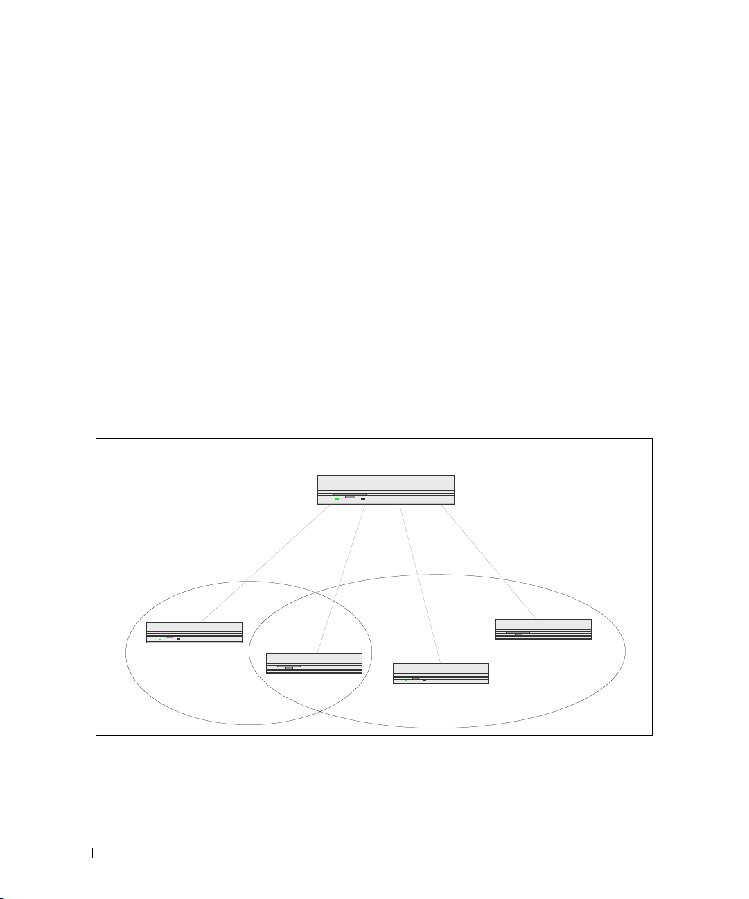
The diagram in this section shows a switch with four ports configured to handle the traffic for two
VLANs. Port 1/g18 handles traffic for both VLANs, while port 1/g17 is a member of VLAN 2 only, and
ports 1/g19 and 1/g20 are members of VLAN 3 only. The script following the diagram shows the
commands you would use to configure the switch as shown in the diagram.
Figure 3-1. VLAN Example Network Diagram
Layer 3 Switch
VLAN2
Port 1/g17
VLAN 2
Port 1/g18
VLANs 2 & 3
Port 1/g19
VLAN 3
VLAN3
Port 1/g20
VLAN 3
CLI Examples
The following examples show how to create VLANs, assign ports to the VLANs, and assign a VLAN as the
default VLAN to a port.
26 Switching Configuration

Example #1: Create Two VLANs
Use the following commands to create two VLANs and to assign the VLAN IDs while leaving the names
blank.
console(config)#vlan database
console(config-vlan)#vlan 2
console(config-vlan)#vlan 3
console(config-vlan)#exit
Example #2: Assign Ports to VLAN2
This sequence shows how to assign ports to VLAN2, specify that frames will always be transmitted
tagged from all member ports, and that untagged frames will be rejected on receipt.
console(config)#interface ethernet 1/g17
console(config-if-1/g17)#switchport mode general
console(config-if-1/g17)#switchport general allowed vlan add 2 tagged
console(config-if-1/g17)#
console(config-if-1/g17)#exit
console(config)#interface ethernet 1/g18
console(config-if-1/g18)#switchport mode general
console(config-if-1/g18)#switchport general allowed vlan add 2 tagged
console(config-if-1/g18)#
console(config-if-1/g18)#exit
switchport general acceptable-frame-type tagged-only
switchport general acceptable-frame-type tagged-only
Example #3: Assign Ports to VLAN3
This example shows how to assign the ports that will belong to VLAN 3. Untagged frames will be
accepted on ports 1/g19 and 1/g20.
Note that port 1/g18 belongs to both VLANs and that port 1/g17 does not belong to VLAN 3.
console(config)#interface ethernet 1/g18
cconsole(config-if-1/g18)#switchport general allowed vlan add 3
console(config-if-1/g18)#exit
console(config)#interface ethernet 1/g19
console(config-if-1/g19)#switchport general allowed vlan add 3
console(config-if-1/g19)#exit
console(config)#interface ethernet 1/g20
console(config-if-1/g20)#switchport general allowed vlan add 3
Switching Configuration 27

Example #4: Assign VLAN3 as the Default VLAN
This example shows how to assign VLAN 3 as the default VLAN for port 1/g18.
console(config)#interface ethernet 1/g18
console(config-if-1/g18)#switchport general pvid 3
Example #5: Assign IP Addresses to VLAN 2
In order for the VLAN to function as a routing interface, you must enable routing on the VLAN and on
the switch. Routing is only permitted on VLAN interfaces. Routing on physical interfaces is not
supported.
console#configure
console(config)#interface vlan 2
console(config-if-vlan2)#ip address 192.168.10.33 255.255.255.0
console(config-if-vlan2)#routing
console(config-if-vlan2)#exit
console(config)#ip routing
Example #6: View Information About VLAN 2
console#show ip interface vlan 2
Primary IP Address........................ 192.168.10.33/255.255.255.0
Routing Mode.............................. Enable
Administrative Mode....................... Enable
Forward Net Directed Broadcasts........... Disable
Proxy ARP................................. Enable
Local Proxy ARP........................... Disable
Active State.............................. Inactive
MAC Address............................... 00FF.F2A3.888A
Encapsulation Type........................ Ethernet
IP MTU.................................... 1500
Bandwidth................................. 10000 kbps
Destination Unreachables.................. Enabled
ICMP Redirects............................ Enabled
28 Switching Configuration

Web Interface
Use the following screens to perform the same configuration using the Web Interface:
•
Switching > VLAN > Membership
Switching > VLAN > Port Settings.
•
. To create VLANs and specify port participation.
To specify the PVID and mode for the port.
IP Subnet and MAC-Based VLANs
In addition to port-based VLANs, the switch also supports VLANs that are based on the IP address or
MAC address of a host. With IP subnet and MAC-based VLANs, the VLAN membership is determined
by the address of the host rather than the port to which the host is attached.
CLI Examples
The following examples show how to associate an IP subnet with a VLAN, a specific IP address with a
VLAN, and a MAC address with a VLAN.
Example #1: Associate an IP Subnet with a VLAN
This example shows how to configure the switch so that all hosts with IP addresses in the 192.168.25.0/24
network are members of VLAN 10.
console#configure
console(config)#vlan database
console(config-vlan)#vlan association subnet 192.168.25.0 255.255.255.0 10
Example #2: Associate an IP Address with a VLAN
This example shows how to configure the switch so a host with an IP addresses of 192.168.1.11 is a
member of VLAN 10.
console#configure
console(config)#vlan database
console(config-vlan)#vlan association subnet 192.168.1.11 255.255.255.255 10
Example #3: Associate a MAC Address with a VLAN
This example shows how to configure the switch so a host with a MAC address of 00:ff:f2:a3:88:86 is a
member of VLAN 10.
console#configure
console(config)#vlan database
console(config-vlan)#vlan association mac 00:ff:f2:a3:88:86 10
Switching Configuration 29

Example #4: Viewing IP Subnet and MAC-Based VLAN Associations
console#show vlan association mac
MAC Address VLAN ID
----------------- ------00FF.F2A3.8886 10
console#show vlan association subnet
IP Subnet IP Mask VLAN ID
---------------- ---------------- -------
192.168.25.0 255.255.255.0 10
192.168.1.11 255.255.255.255 10
Protocol-Based VLANs
The software supports protocol-based VLANs, where only packets are bridged based on their layer 3
protocol. Protocol-based VLANs are most often used in situations where network segments contain hosts
running multiple protocols such as ARP, IP, and IPX. You can associate any protocol—identified by the
packet’s Ethertype field (1536 to 65535)—with a VLAN ID.
To identify a protocol with a VLAN, you first create a protocol group and assign a protocol group ID
number. You can also assign a name to the protocol group. Then, you add the protocol’s Ethertype to the
protocol group. Or, you can add a protocol to an existing protocol group.
CLI Example
The following commands create a vlan protocol group, name the group, add a protocol to it, and
associate the protocol group with a port:
console(config)#vlan protocol group 1
console(config)#vlan protocol group name 1 usergroup
console(config)#vlan protocol group add protocol 2 ethertype 0x0800
The following command associates the protocol group with a port 1/g1:
console(config)#interface ethernet 1/g1
console(config-if-1/g1)#protocol vlan group 1
To associate the protocol group with all ports, use the following command:
console(config)#protocol vlan group all 1
30 Switching Configuration
 Loading...