

Page 1

Dell™ Server Console Switch
User's Guide
Page 2

Notes, Cautions, and Warnings
NOTE: A NOTE indicates important information that helps you make
better use of your computer.
CAUTION: A CAUTIO N indicates potent ial damage to
hardware or loss of data if instructions are not followed.
WARNING: A WARNING indicat es a potential for property
damage, personal injury, or death.
____________________
Information in this publication is subject t o change without notice.
© 2011 Dell Inc. All rights reserved.
Reproduction of these materials in any manner whatsoever without the written
permission of Dell Inc. is strictly forbidden.
Trademarks used in this text: Dell, the DEL L logo, and PowerEdge are trademarks
of Dell I nc.; Avocent is a r egistered trademark of Avocent Corporation. Microsoft®,
Windows®, Windows Ser ver®, MS-DOS®, and Windows Vista® are either
trademarks or r egistered trademarks of Microsoft Corporation in the United States
and/or other countries. Red Hat Enterprise Linux® and Enterprise Linux® are
registered trademar ks of Red Hat, I nc. in the United States and/or other countries.
Other tr ademarks and trade names may be used in this publication to ref er to either
the entities claiming the marks and names or their products. Dell Inc. disclaims any
proprietary inter est in trademarks and trade names other than its own.
59 0- 10 68-50 1A
Mod e l 108 1AD/2 16 1AD Se rve r Co nso le Switch
July 2 011
Page 3

Contents
Product Overview 1
Features and Benefits 1
Dell Remote Access Key (RAK) 4
Safety Precautions 7
General 7
Reduce Cable Bulk 1
SIP Intelligent Modules 1
Multiplatform Support 2
User Interfaces 2
Virtual Media and Smart Card-capable Switches 3
IPv4 and IPv6 Capabilities 3
Access the SCS Using a Standard TCP/IP Network 4
Upgradeable 4
Two-tier Expansion 4
KVM Remote Access 4
Avocent Management Software Plug-in 5
Local Video Scaling 5
Encryption 5
LAN Related Precautions 9
Installation 11
Getting Started 11
Setting Up Your Network 12
SCS Quick Setup 13
Rack Mounting the Switch 14
Rack Mounting Safety Considerations 14
Contentsxxx | xxx3
Page 4

Installing the Dell ReadyRails System 15
Installing the Switch 20
Connecting the SCS Hardware 23
Tiering Your Switch Using a SIP 26
Adding a Tiered Switch 29
Adding a Tiered Legacy Switch 31
Adding a Port Expansion Module (Optional) 33
Configuring Your SCS 35
Setting Up the Built-in Web Server 35
Connecting to the OBWI Through a Firewall 35
Verifying Power Status 37
Adjusting Mouse Settings on Target Devices 37
Local OSCAR User Interface 39
Main Dialog Box Functions 39
Viewing and Selecting Ports and Devices 39
Viewing Switch System Status 41
Selecting Devices 42
Soft Switching 43
Navigating the OSCAR Interface 43
Connecting Local Virtual Media 45
Contentsxxx | xxx4
Setup Dialog Box Functions 46
Changing the Display Behavior 47
Controlling the Status Flag 48
Setting the Keyboard Country Code 49
Assigning Device Types 50
Assigning Device Names 50
Configuring Network Settings 51
Commands Dialog Box Functions 52
Selecting Devices for Scan Mode 53
Page 5

Enabling or Disabling Scan Mode 54
Viewing and Disconnecting User Connections 54
Displaying Version Information and Upgrading Firmware 55
OBWI Operation 57
Using the OBWI 59
Viewing System Information 61
Scan Mode 63
Generating a Certificate 63
Tools - Rebooting and Upgrading 65
Rebooting the SCS 65
Upgrading SCS Firmware 65
Saving and Restoring SCS Configurations and User Databases 66
Property Identity and Location Settings 68
Viewing Version Information 68
Network Settings 68
SNMP Settings 70
Auditing Event Settings 71
Setting Event Destinations 71
Ports Settings- Configuring a SIP 72
Deleting SIPs 72
Upgrading SIPs 72
Launching a Session 73
General Sessions Settings 74
Local User Account Settings 75
Virtual Media Session Settings 76
Contentsxxx | xxx5
Page 6

Avocent User Account Settings 78
Override Admin 78
Active Sessions 79
Closing a Session 79
Video Viewer 81
Changing the Toolbar 84
Window Size 84
Adjusting the View 85
Refreshing the Image 86
Video Settings 86
Target Video Settings 88
Automatic Video Adjustment 89
Video Test Pattern 89
Vendor-specific Video Settings 89
Color Settings 89
Contrast and Brightness 90
Contentsxxx | xxx6
Noise Settings 90
Mouse Settings 91
Cursor Type 91
Mouse Scaling 94
Mouse Alignment and Synchronization 94
Virtual Media 95
Requirements 95
Sharing and Preemption Considerations 96
Virtual Media Dialog Box 96
Opening a Virtual Media Session 97
Page 7

Closing a Virtual Media Session 100
Smart Cards 101
Keyboard Pass-through 102
Macros 103
Saving the View 103
Closing a Session 103
Terminal Operation 105
Network Configuration 105
Other Console Main Menu Options 106
Firmware Management 107
Enable Debug Messages 107
Set/Change Password 107
Restore Factory Defaults 107
Reset Switch 107
Set Web Interface Ports 107
Exit 107
Appendix A: MIB and SNMP Traps 109
Appendix B: Setup Port Pinouts 113
Appendix C: Using Avocent Serial IQ Modules 115
Serial IQ Module Modes 115
Configuring the Serial IQ Module 115
Creating a Serial IQ Module Macro 118
Using History Mode 119
Contentsxxx | xxx7
Page 8

Serial IQ Module Pinouts 120
Appendix D: Sun Advanced Key Emulation 121
Appendix E: UTP Cabling 123
UTP Copper Cabling 123
Wiring Standards 123
Cabling Installation, Maintenance, and Safety Tips 124
Appendix F: Technical Specifications 127
Appendix G: Technical Support 131
Contentsxxx | xxx8
Page 9

1
Product Overview
The Dell 1081AD/2161AD Server Console Switch (SCS) is an analog keyboard,
video, and mouse (KVM) switch that provides flexible, centralized local access
to data center servers. It can also provide centralized remote access to data
center servers when used in conjunction with the optional Remote Access Key
(RAK).
Features and Benefits
Reduce Cable Bulk
With device densities continually increasing, cable bulk remains a major concern
for network administrators. The SCS significantly reduces KVM cable volume in
the rack by utilizing the innovative Server Interface Pod (SIP) and single,
industry-standard Unshielded Twisted Pair (UTP) cabling. This allows a higher
device density while providing greater airflow and cooling capacity.
SIP Intelligent Modules
The SCS supports SIPs that are powered directly from the target device and
provide Keep Alive functionality when the SCS is not powered. The SIPs with
CAT 5 design dramatically reduce cable clutter while providing optimal
resolution and video settings. The built-in memory of SIPs simplifies
configuration by assigning and retaining unique device names and Electronic ID
(EID) numbers for each attached device.
PS/2 and USB SIPs are available allowing direct KVM connectivity to devices.
The USB2+CAC SIP is also available. The SCS is offered with 8 or 16 ARI
Product Overviewxxx | xxx1
Page 10

ports that are used to connect SIPs to the SCS. Then utilizing the SIPs, you can
attach additional switches to expand your SCS system. This flexibility allows
you to add capacity as your data center grows.
Multiplatform Support
Dell SIPs are available for use with the SCS to support PS/2, USB, USB2, and
USB2+CAC device environments.
Interoperability with Avocent®IQ Module Intelligent Cabling may also be used
to connect local devices to the SCS. PS/2, USB, and Sun®module options are
available. For more information, please refer to the appropriate Avocent
installer/user guide for your product or visit avocent.com/manuals for more
information.
User Interfaces
The SCS is equipped with two “point-and-click” interfaces to manage the SCS
locally. They are the local user interface (UI), referred to as OSCAR™, and the
on-board web interface (OBWI). Using the configuration options provided by
these interfaces, you can tailor your SCS to your specific application. The
OBWI can also be used to access and control any attached devices, and handle
all basic KVM needs remotely.
NOTE: Remote KVM sessions via the OBWI requires the installation of the Dell RAK.
OSCAR Interface
The OSCAR interface, accessed using the local port, features intuitive menus
and operation modes to configure your SCS and devices. Devices can be
identified by name, EID, or port number.
The OSCAR interface allows you to protect your system with a screen saver
password. When the screen saver mode engages, access is prohibited until the
appropriate password is entered to reactivate the system. By typing Help in the
password dialog, you are directed to Dell Technical Support. Recommended
usage for the SCS is in a data center infrastructure protected by a firewall.
2xxx | Product Overviewxxx
Page 11

OBWI
You can also use the OBWI to manage your SCS. The OBWI is launched
directly from the SCS and does not require a software server or any installation.
With the addition of the optional Dell RAK installed, you can also establish
remote KVM and virtual media sessions to target devices. For more information,
see "Dell Remote Access Key (RAK)" on page 4.
Terminal Console Interface
The terminal console interface is accessed through the "10101" setup port. A
terminal screen or a PC running terminal emulation software can be used to
access these screens.
Virtual Media and Smart Card-capable Switches
The SCS allows you to view, move, or copy data located on local media and
smart cards. Smart cards are pocket-sized cards that store and process
information including identification and authentication information to enable
access to computers, networks, and secure rooms or buildings.
A virtual media or a smart card reader can be connected directly to the USB
ports on the SCS. In addition, virtual media or smart card readers may be
connected to any remote workstation that is running the remote OBWI, SCS
Software, or Avocent management software, and is connected to the SCS using
an Ethernet connection.
NOTE: To open a virtual media or smart card session with a target device, you must
first connect the target device to an SCS using a USB 2.0 or USB+CAC SIP.
IPv4 and IPv6 Capabilities
The SCS is compatible with systems using either of the currently used Internet
Protocol Versions, IPv4 or IPv6. You can change the network settings and
choose either IPv4 or IPv6 mode via the terminal console, OSCAR interface, or
OBWI.
Product Overviewxxx | xxx3
Page 12

Access the SCS Using a Standard TCP/IP Network
The device is accessible for configuration via the standard TCP/IP Network. If
the optional Dell RAK is installed, you can access all attached systems via
Ethernet. See "Dell Remote Access Key (RAK)" on page 4.
NOTE: The client connects to the SCS using an Internet browser.
NOTE: KVM over IP sessions are supported when the Dell RAK is installed.
Upgradeable
Upgrade your SCS and SIPs at any time to ensure you are always running the
most current firmware version available. Upgrades can be initiated through the
OSCAR interface, OBWI, or the terminal console screens. The SCS can also be
configured to perform automatic firmware upgrades of SIPs. For more
information, see "Tools - Rebooting and Upgrading" on page 65.
Two-tier Expansion
The SCS allows you to tier one additional SCS, CS, or RCS from each ARI port
on the primary SCS. Each tiered SCS is attached in the same manner as any
device. This additional tier of units allows you to attach up to 512 servers in
one system. See "Tiering Your Switch Using a SIP" on page 26.
Dell Remote Access Key (RAK)
The optional Dell RAK, installed in the USB port, supports the following
features.
KVM Remote Access
A single KVM remote user is supported using the RAK. With the RAK, you can
manage remote operating system installation, operating system recovery, hard
drive recovery or duplication, BIOS updating, and server backup.
4xxx | Product Overviewxxx
Page 13

Avocent Management Software Plug-in
Avocent management software may be used with the SCS to allow IT
administrators to securely and remotely access and monitor target devices on
multiple platforms through a single, web-based user interface. A session may be
launched to a device from a single point of access. For more information, see the
Technical Bulletin for the management software plug-in.
Local Video Scaling
The SCS digitizes a video signal with a maximum pixel resolution of up to 1600
x 1200 or 1680 x 1050 (widescreen), depending on the length of cable separating
your SCS and devices.
Encryption
The SCS supports 128-bit SSL(ARCFOUR), AES, DES, and 3DES encryption
of keyboard/mouse, video, and virtual media sessions.
Product Overviewxxx | xxx5
Page 14
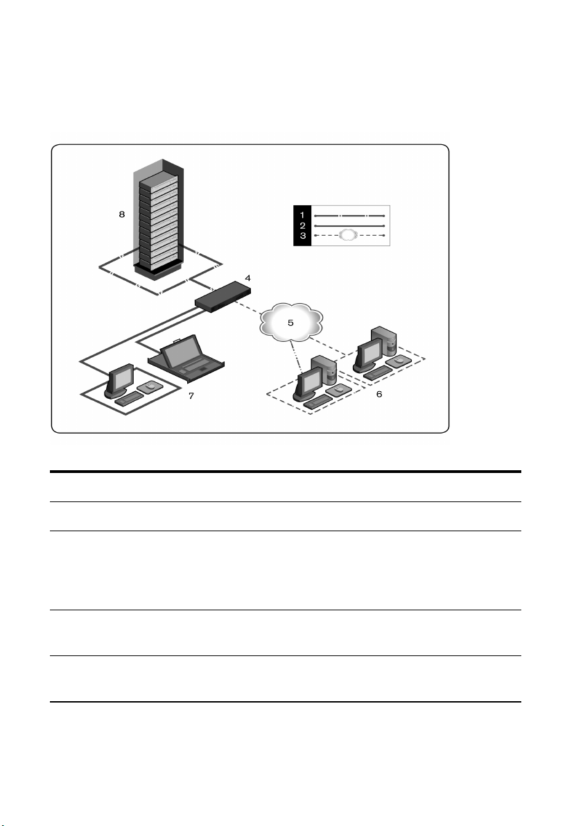
Figure 1.1: Example Server Con sole Switch Config uration
Table 1.1: Descript ions for Figure 1.1
Number Description Number Description
1 UTP Connection 5 Ethernet
2
Local KVM Connection to
the Server Console Switch
3 Remote IP Connection 7
4
Server Console Switch
(2161AD shown)
6xxx | Product Overviewxxx
Digital Users (computer with Internet
6
Browser for OBWI or RCS Software
and/or Avocent Management Software
Server [requires the Dell RAK])
Local Analog Users (OSCAR Interface
and/or Local LCD Tray)
8 Servers/Target Devices
Page 15

Safety Precautions
This document pertains only to the Dell 1081AD/2161AD Server Console
Switch. You should also refer to the following additional safety instructions.
• Dell Safety Sheet
• Dell RTF Regulatory Tech Bulletin
General
Use the following safety guidelines to help ensure your own personal safety and
to help protect your system and working environment from potential damage.
CAUTION: The power supplies in your system may produce high voltages
and energy hazards, which can cause bodily harm. Only t rained service
technicians are authorized to remove the covers and access any of the
components inside the system. This warning applies t o the Dell™ Server
Console Switch, Dell™ PowerEdge™ server, and Dell PowerVault™ storage
system.
• Observe and follow service markings.
• Do not service any product except as explained in your system
documentation.
• Opening or removing covers that are marked with the triangular symbol with
a lightning bolt may expose you to electrical shock.
• Components inside these compartments should be serviced only by a
trained service technician.
• This product contains no serviceable components. Do not attempt to open.
• If any of the following conditions occur, unplug the product from the
electrical outlet and replace the part or contact your trained service provider:
• The power cable, extension cable, or plug is damaged.
• An object has fallen into the product.
Product Overviewxxx | xxx7
Page 16

• The product has been exposed to water.
• The product has been dropped or damaged.
• The product does not operate correctly when you follow the operating
instructions.
• Keep your system away from radiators and heat sources. Also, do not block
cooling vents.
• Do not spill food or liquids on your system components, and never operate
the product in a wet environment. If the system gets wet, see the
appropriate section in your troubleshooting guide or contact your trained
service provider.
• Use the product only with approved equipment.
• Allow the product to cool before removing covers or touching internal
components.
• Operate the product only from the type of external power source indicated
on the electrical ratings label. If you are not sure of the type of power source
required, consult your service provider or local power company.
NOTE: To help avoid damaging your system, be sure the voltage selection switch (if
provided) on the power supply is set for the voltage that most closely matches the AC
power available in your location. Also be sure that your monitor and attached devices
are electrically rated to operate.
• Be sure that your monitor and attached devices are electrically rated to
operate with the power available in your location.
• Use only power cables provided with this product.
• To help prevent electric shock, plug the system and peripheral power cables
into properly grounded electrical outlets. These cables are equipped with
three-prong plugs to help ensure proper grounding. Do not use adaptor plugs
or remove the grounding prong from a cable.
8xxx | Product Overviewxxx
Page 17

• Observe extension cable and power strip ratings. Make sure that the total
ampere rating of all products plugged into the power strip does not exceed
80 percent of the ampere ratings limit for the power strip.
• To help protect your system from sudden, transient increases and decreases
in electrical power, use a surge suppressor, line conditioner, or
uninterruptible power supply (UPS).
• Position system cables and power cables carefully. Route cables so that they
cannot be stepped on or tripped over. Be sure that nothing rests on any
cables.
• Do not modify power cables or plugs. Consult a licensed electrician or your
power company for site modifications. Always follow your local/national
wiring rules.
LAN Related Precautions
• Do not connect or use during a lightning storm. There may be a risk of
electrical shock from lightning.
• Never connect or use in a wet environment.
Product Overviewxxx | xxx9
Page 18

10xxx | Product Overviewxxx
Page 19

2
Installation
The SCS uses TCP/IP for communication over Ethernet. For the best system
performance, use a dedicated, switched 100BaseT network. You can also use
10BaseT Ethernet.
You may use the terminal software, OSCAR interface, or the OBWI to manage
your SCS system. The OBWI manages a single switch and its connections. With
the optional Dell RAK, you can also perform KVM and serial switching tasks
using the OBWI or Avocent management software. For more information about
Avocent management software, visit http://www.avocent.com/dell.
NOTE: The RCS software can be used to manage other switches. For more
information, please refer to the appropriate installer/user guide for your product.
NOTE: Ensure that every switch has been upgraded to the most recent version of
firmware. For information on upgrading the switch using the OBWI, see "Tools Rebooting and Upgrading" on page 65.
Getting Started
The following items are supplied with the SCS. Before installing your SCS,
locate the necessary items for proper installation.
• Server Console Switch
• Power Cord
• 0U Mounting Bracket Kit
• 1U Mounting Bracket Kit (two additional rails are pre-mounted to the SCS
assembly)
• Cable and Adaptors for the 10101 Console SetupPort
Installationxxx | xxx11
Page 20

• User Documentation CD
• Server Console Switch Quick Installation Guide
• Dell Rack Mounting Quick Installation Guide
• Dell Safety Sheet
• Dell RTF Regulatory Technical Bulletin
Additional items needed:
• One Dell SIP or Avocent IQ module per attached device
• One CAT 5 Patch Cable (up to 30 meters) per attached device
Optional Items:
• Dell Remote Access Key (RAK)
• Port Expansion Module (PEM)
NOTE: You cannot open a virtual media session or a CAC session if the device is
connected via a PEM.
Setting Up Your Network
The SCS uses IP addresses to uniquely identify the SCS and attached devices.
The SCS supports both Dynamic Host Configuration Protocol (DHCP) and
static IP addressing. Make sure that an IP address is reserved for each SCS and
that each IP address remains static while the SCS is connected to the network.
Keyboards
A USB keyboard and mouse can be connected to the analog ports of the SCS.
NOTE: The SCS also supports the use of multiple keyboards and multiple mice on the
analog port. The use of more than one input device simultaneously, however, may
produce unpredictable results.
12xxx | Installationxxx
Page 21

SCS Quick Setup
The following is a quick setup list. For detailed rack mounting and installation
instructions, see "Rack Mounting the Switch" on page 14.
1 Unpack the SCS and verify that all components are present and in good
condition.
2 Install the SCS hardware and connect a SIP or Avocent IQ module to each
target device or tiered SCS. Connect each SIP or Avocent IQ module to the
SCS with CAT 5 cabling and connect the keyboard, monitor, and mouse
connectors to the analog ports of the SCS.
3 Connect the local port peripherals to the appropriate ports on the back
panel of the SCS and set up the network configuration. The IP address can
be set here or from the RCS software. Dell recommends using a static IP
address.
4 For the local port connection, input all device names using the OSCAR
interface or the OBWI.
5 Adjust mouse acceleration on each device to Slow or None.
To set up the RCS software (see the Remote Console Switch Software User's
Guide):
1 Install the RCS software on each client workstation.
2 From one client workstation, launch the RCS software.
3 If you have installed the RAK, click the New Server Console Switch task
button to add the new switch to the RCS software database. If you
configured the IP address as described above, select Yes, the product already
has an IP address; otherwise select No, the product does not have an IP
address.
The RCS software will find the switch and all SIPs connected to it and
display the names in the Explorer.
Installationxxx | xxx13
Page 22

NOTE: Using RCS software you can add and manage the Dell SCS, Dell RCS, and
some Avocent switches.
4 Set properties and group devices as desired into locations, sites, or folders
through the Explorer.
5 Create user accounts through the OBWI. For more information, see "Local
User Account Settings" on page 75.
6 If the local user adds, deletes, or renames any SIPs after you have loaded this
file, you can resynchronize your local SCS by selecting the SCS and clicking
Resync. To control a connected device, select it in the Explorer and click
the Connect Video task button to launch a device session in the Viewer.
7 Select View - Scaling to adjust the resolution and select View - Color of the
device video quality in the Viewer.
Rack Mounting the Switch
You may either place the switch on the rack shelf or mount the switch directly
into a 19" wide, EIA-310-E compliant rack (four-post, two-post, or threaded
methods). The Dell ReadyRails™ system is provided for 1U front-rack, 1U rearrack, and two-post installations. The ReadyRails system includes two separately
packaged rail assemblies and two rails that are shipped attached to the sides of
the switch. In addition, one mounting bracket is provided for 0U configurations,
and one blanking panel is provided for rear-rack installations.
WARNING: This is a condensed reference. Read the safet y instructions in
your Safety, Environmental, and Regulat ory Information booklet before you
begin.
NOTE: The illustrations in this document are not intended to represent a specific
switch.
Rack Mounting Safety Considerations
• Rack Loading: Overloading or uneven loading of racks may result in shelf or
rack failure, causing damage to equipment and possible personal injury.
Stabilize racks in a permanent location before loading begins. Mount
14xxx | Installationxxx
Page 23

components beginning at the bottom of the rack, then work to the top. Do
not exceed your rack load rating.
• Power considerations: Connect only to the power source specified on the
unit. When multiple electrical components are installed in a rack, ensure
that the total component power ratings do not exceed circuit capabilities.
Overloaded power sources and extension cords present fire and shock
hazards.
• Elevated ambient temperature: If installed in a closed rack assembly, the
operating temperature of the rack environment may be greater than room
ambient. Use care not to exceed the 50°C maximum ambient temperature
of the switch.
• Reduced air flow: Install the equipment in the rack so that the amount of
airflow required for safe operation of the equipment is not compromised.
• Reliable earthing: Maintain reliable earthing of rack-mounted equipment.
Pay particular attention to supply connections other than direct
connections to the branch circuit (for example, use of power strips).
• Product should not be mounted with the rear panel facing in the downward
position.
Installing the Dell ReadyRails System
The ReadyRails system is provided to easily configure your rack for installation
of your switch. The ReadyRails system can be installed using the 1U tool-less
method or one of three possible 1U tooled methods (two-post flush mount, twopost center mount, or four-post threaded).
1U Tool-less Configuration (Four-post Square Hole or Unthreaded Round Hole)
1 With the ReadyRails flange ears facing outward, place one rail between the
left and right vertical posts. Align and seat the rear flange rail pegs in the
rear vertical post flange. In Figure 2.1, item 1 and its extractions illustrate
how the pegs appear in both the square and unthreaded round holes.
Installationxxx | xxx15
Page 24
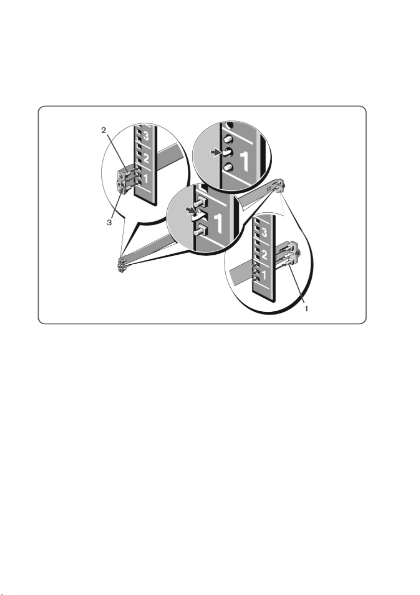
Figure 2.1: 1U Tool-less Config uration
2 Align and seat the front flange pegs in the holes on the front side of the
vertical post (item 2).
3 Repeat this procedure for the second rail.
4 To remove each rail, pull on the latch release button on each flange ear
(item 3) and unseat each rail.
Two-Post Flush-Mount Configuration
1 For this configuration, the castings must be removed from the front side of
each ReadyRails assembly (Figure 2.2, item 1). Use a Torx™ driver to
remove the two screws from each front flange ear (on the switch side of the
rail) and remove each casting. Retain castings for future rack requirements.
It is not necessary to remove the rear flange castings.
16xxx | Installationxxx
Page 25
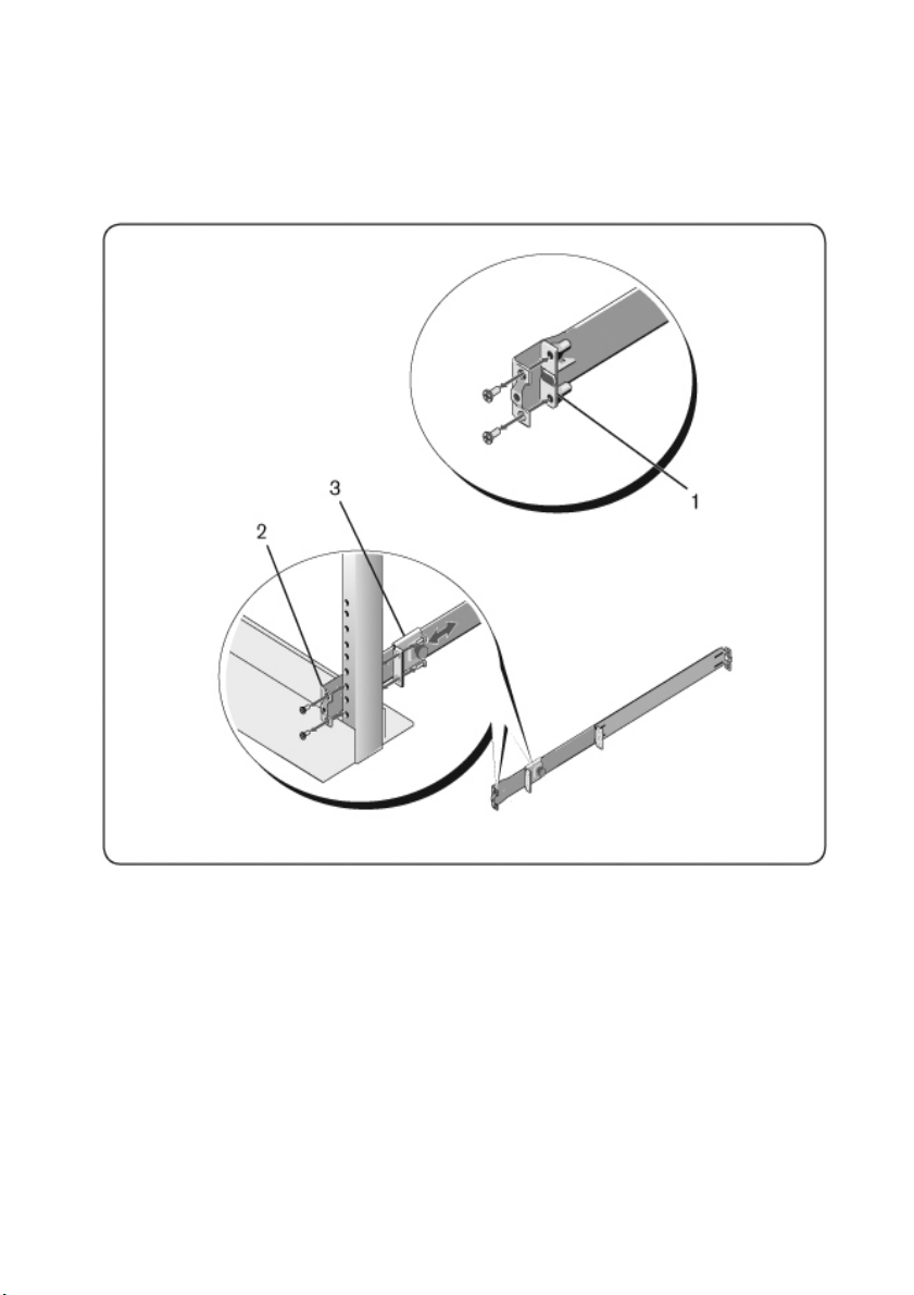
Figure 2.2: Two-po st Flush-mount Co nfiguration
2 Attach one rail to the front post flange with two user-supplied screws (item
2).
3 Slide the plunger bracket forward against the vertical post and secure the
plunger bracket to the post flange with two user-supplied screws (item 3).
4 Repeat this procedure for the second rail.
Installationxxx | xxx17
Page 26
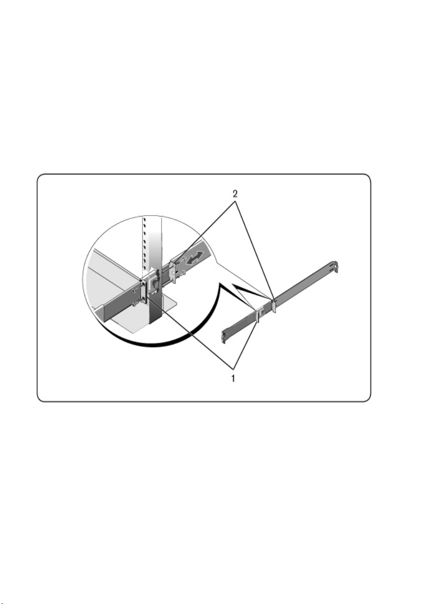
Two-post Center-mount Configuration
1 Slide the plunger bracket rearward until it clicks into place and secure the
bracket to the front post flange with two user-supplied screws (Figure 2.3,
item 1).
Figure 2.3: Two-po st Center-mount Con figuration
2 Slide the back bracket towards the post and secure it to the post flange with
two user-supplied screws (item 2).
3 Repeat this procedure for the second rail.
Four-post Threaded Configuration
1 For this configuration, the flange ear castings must be removed from each
end of the ReadyRails assemblies. Use a Torx™ driver to remove the two
18xxx | Installationxxx
Page 27

screws from each flange ear and remove each casting (Figure 2.4, item 1).
Retain castings for future rack requirements.
2 For each rail, attach the front and rear flanges to the post flanges with two
user-supplied screws at each end (item 2).
Figure 2.4: Four-post Threaded Config uration
Installationxxx | xxx19
Page 28
Installing the Switch
The switch may be mounted in the 1U rear-rack, 1U front-rack, 1U two-post
(flush and center), and 0U configurations. The following are examples of 1U rearrack, 1U front-rack, and 0U configurations. For 1U two-post (flush and center)
configurations, you can slide the switch into the rails in the same manner as the
four-post configurations.
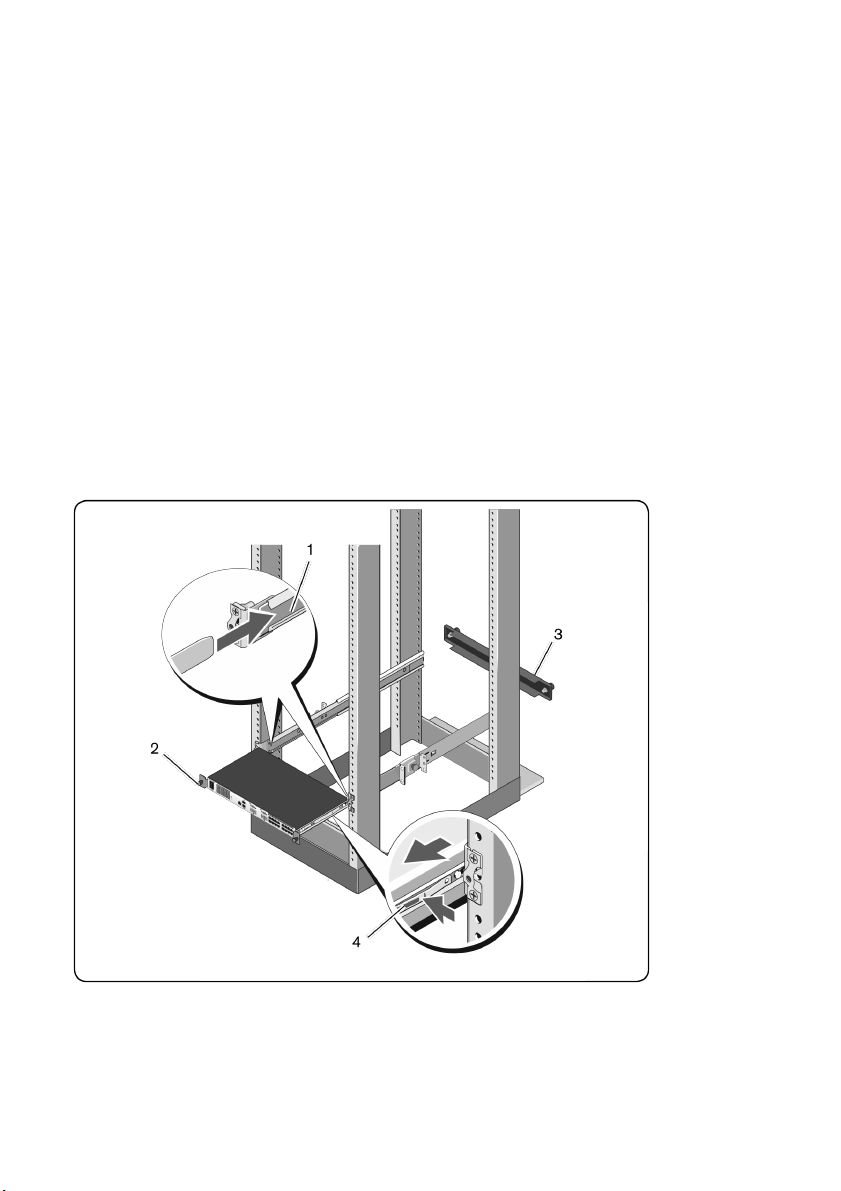
1U Rear-rack Installation
1 Insert the ends of the rails that are attached to the switch into the
ReadyRails assembly and push the switch into the rack (Figure 2.5, item 1).
Figure 2.5: 1U Rear-rack Installation
2 Secure each switch rail with the thumbscrew (item 2).
20xxx | Installationxxx
Page 29

3 (Optional) Assemble the blanking panel to the rails on the front side of the
rack and tighten the thumbscrews (item 3).
To remove the switch from the rack:
1 Unscrew the thumbscrews and pull the switch assembly out of the rack until
the travel stops are reached. The travel stop position is intended to provide
the opportunity to reposition the rail grip; it is not intended for service.
2 Locate the blue tabs on the sides of the switch rails (item 4).
3 Push the tabs inward and continue pulling the assembly until the switch
rails are clear of the ReadyRails assemblies.
1U Front-rack Installation
Before installation, the rails that are attached to the switch must be reconfigured.
1 On each switch rail, lift the tab under the front standoff and slide the rail
forward as you lift the rail from the switch (Figure 2.6, item 1).
Installationxxx | xxx21
Page 30
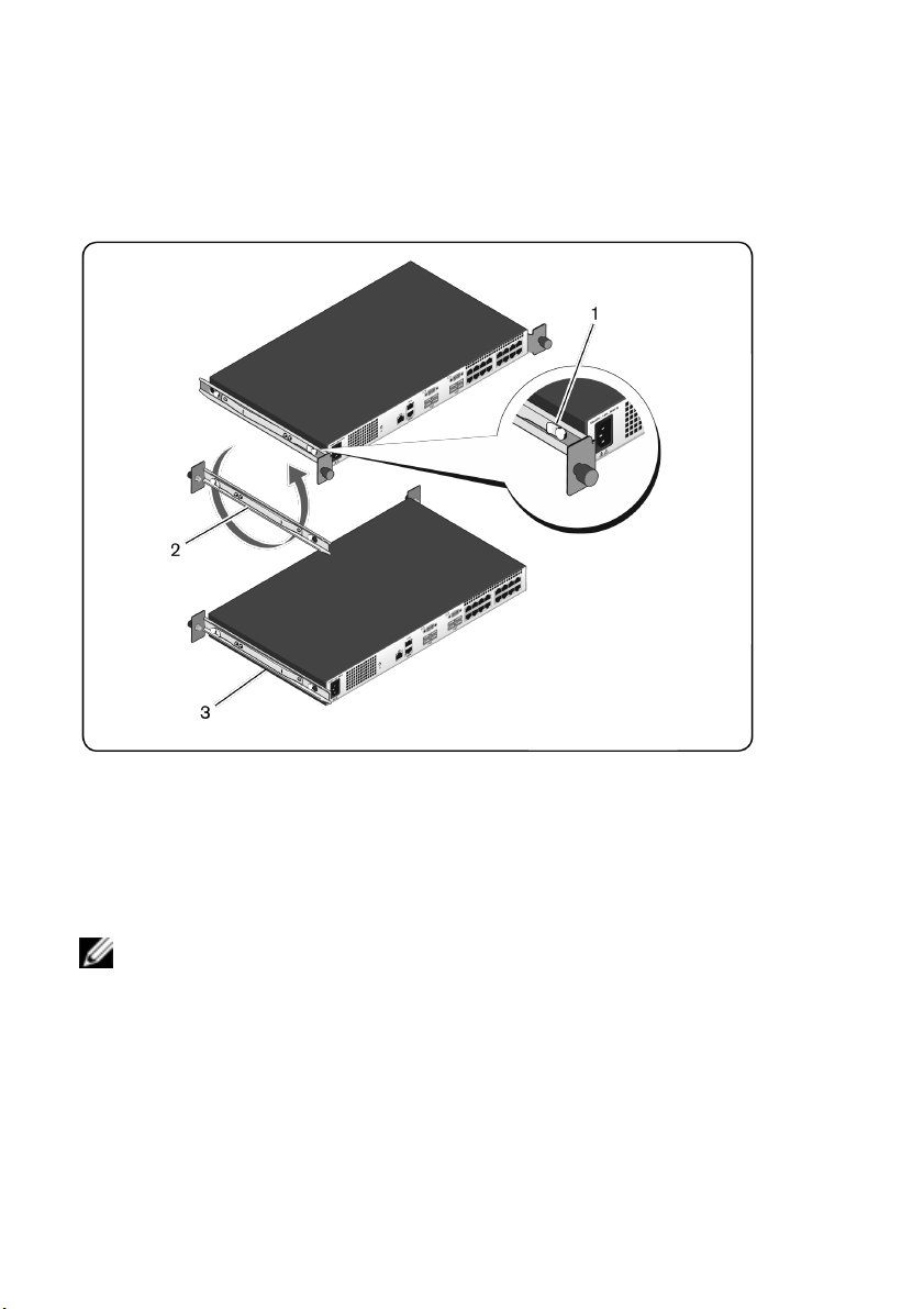
Figure 2.6: Rot ating the Switch Rails
2 Rotate each rail 180° (item 2) and then reassemble each rail to the switch
(item 3).
3 Refer to the 1U rear-rack instructions to insert and remove the switch
assembly from the ReadyRails system.
NOTE: No blanking panel is required for this configuration.
0U Installation
1 Align and assemble the 0U mounting bracket to the switch rails (Figure 2.7,
item 1). Tighten the thumbscrews (item 2).
2 Insert the mounting bracket hooks into the rack holes and push down until
the blue button pops out and locks the bracket into place.
22xxx | Installationxxx
Page 31

Figure 2.7: 0U Installat ion
To remove the switch assembly, press the blue button (item 3) to unseat the
bracket and then lift the assembly from the posts.
Connecting the SCS Hardware
Figure 2.8 illustrates an example configuration for the SCS.
Installationxxx | xxx23
Page 32

Figure 2.8: Basic SCS Configuration
24xxx | Installationxxx
Page 33

Table 2.1: Basic SCS Configuration Descriptions
Number Description Number Description
1
2 Power Cord 8
3 Analog Users (2) 9 Target Device Ports
4
5 LAN/Network 11 Servers/Target Devices
6
NOTE: The SCS switch supports connecting to another appliance via an ACI
connection. This connection requires that the secondary appliance in the tier have an
ACI connector on the user side.
SCS (16-Port Model
Shown)
Digital User (requires
the RAK)
10101 Console Setup
Port
7 ACI Connection
External Virtual Media - USB
Connections
10 SIPs
To connect and turn on your SCS:
CAUTION: To reduce the risk of elect ric shock or damage to your
equipment, do not disable t he jumper cord grounding plug. The grounding
plug is an important safet y feature. Plug the jumper cord into a grounded
(earthed) outlet that is easily accessible at all times. Disconnect the power
from the unit by unplugging t he jumper cord from either the power source or
the unit.
NOTE: If the building has 3-phase AV power, ensure that the computer and monitor are
on the same phase to avoid potential phase-related video and/or keyboard problems.
NOTE: The maximum supported cable length from SCS to server is 30 meters.
• Do not disable the power grounding plug. The grounding plug is an
important safety feature.
Installationxxx | xxx25
Page 34

• Connect the jumper cord into a grounded (earthed) outlet that is easily
accessible at all times.
• Disconnect the power from the product by unplugging the jumper cord
from either the power source or the product.
• This product has no user-serviceable parts inside the product enclosure.
Do not open or remove product cover.
1 Connect your VGA monitor and USB keyboard and mouse cables to the
appropriately labeled ports.
2 Connect one end of a UTP cable (4-pair, up to 98 ft/30 m) to an available
numbered port. Connect the other end to an RJ-45 connector of a SIP.
3 Connect a SIP to the appropriate port on the back of a device. Repeat steps
2 and 3 for all devices you want to connect.
NOTE: When connecting to a Sun Microsystems server, you must use a multi-sync
monitor in the local port to accommodate Sun computers that support both VGA and
sync-on-green or composite sync.
4 Connect a user-supplied UTP cable from the Ethernet network to the LAN
port on the back of the SCS. Network users will access the SCS through this
port.
5 Turn on each device, then locate the jumper cord that came with the SCS.
Connect one end to the power socket on the rear of the SCS. Connect the
other end into an appropriate power source.
6 (Optional) Connect the virtual media or smart card readers to any of the
USB ports on the SCS.
NOTE: For all virtual media sessions, you must use a USB2 or USB2+CAC SIP.
Tiering Your Switch Using a SIP
Figure 2.9 illustrates a typical SIP connection between the SCS and a device.
To connect a SIP to each device:
NOTE: When tiering devices, the SCS closest to the actual user is the primary SCS.
26xxx | Installationxxx
Page 35

1 Locate the SIPs for your SCS.
2 If you are using a PS/2 SIP connection, attach the color-coded ends of the
SIP cable to the appropriate keyboard, monitor, and mouse ports on the
first device you will be connecting to this SCS. If you are using a USB
connection, attach the plug from the SIP to the USB port on the first
device you will be connecting to this SCS.
3 To the RJ-45 connector on the SIP, attach one end of the CAT 5 cabling
that will run from your SIP to the SCS. See "SIP Connection" on page 28.
4 Connect the other end of the CAT 5 cable to the desired ARI port on the
back of your SCS.
5 Repeat steps 2-4 for all devices you wish to attach.
NOTE: Turn off the switch before servicing. Always disconnect the jumper cord from
the power source.
NOTE: In addition to Dell SIPs, the switch may also be connected to devices using
Avocent IQ modules, including Sun IQ modules.
Installationxxx | xxx27
Page 36

Figure 2.9: SIP Connection
Table 2.2: Descript ions for Figure 2.9
Number Description
1 CAT 5
2 USB Connection
3 VGA Connection
28xxx | Installationxxx
Page 37

Adding a Tiered Switch
NOTE: The SCS does not support the EL80-DT.
You can tier up to two levels of switches (Figure 2.10), enabling users to
connect to up to 512 devices. In a tiered system, each device port on the main
switch will connect to the ACI port on each tiered switch. Each tiered switch
can then be connected to a device with a SIP or Avocent IQ module.
To tier multiple switches:
1 Attach one end of a UTP cable (up to 30 meters in length) to a device port
on the switch.
2 Connect the other end of the UTP cable to the ACI port on the back of
your tiered switch.
3 Connect the devices to your tiered switch.
4 Repeat these steps for all the tiered switches you wish to attach to your
system.
NOTE: The system will automatically “merge” the two switches. All switches
connected to the tiered switch will display on the main switch list in the local UI.
NOTE: The switch supports one tiered switch per device port of the main switch. You
cannot attach a switch to the tiered switch.
Installationxxx | xxx29
Page 38

Figure 2.10: Tiering the SCS With a UTP An alog Switch
30xxx | Installationxxx
Page 39

Table 2.3: Descript ions for Figure 2.10
Number Description
1 Local User
2 ARI Connection
3 UTP Connection
4 ACI Connection (chain icon)
Adding a Tiered Legacy Switch
Figure 2.11 illustrates a tiered legacy switch configuration.
To add a legacy switch (optional):
1 Mount the SCS into your rack. Locate a UTP cable (up to 30 meters) to
connect your switch to the legacy switch.
2 Attach one end of the UTP cabling to the ARI port on your switch.
3 Connect the other end of the UTP cable to a PS/2 SIP.
4 Connect the SIP to the legacy switch according to the switch
manufacturer's recommendations.
5 Repeat steps 1-4 for all the legacy switches you wish to attach to your
switch.
NOTE: The primary SCS supports only one switch per ARI port or USB port. You cannot
tier a switch to a tiered switch.
Installationxxx | xxx31
Page 40

Figure 2.11: Tiering Legacy Switches
32xxx | Installationxxx
Page 41

Table 2.4: Descript ions for Figure 2.11
Number Description
1 Local User
2 ARI Connection
3 SIP
4 PS2 Connection
5 Target Device Connection
Adding a Port Expansion Module (Optional)
A Port Expansion Module (PEM) allows you to expand each ARI port to
accommodate up to eight devices instead of one. See Figure 2.12 and its
description table.
NOTE: The PEM operates passively. Therefore, once a user accesses a device
attached to a PEM, any subsequent users attempting to access any of the devices
attached to that PEM will be blocked.
NOTE: You cannot open a virtual media session or a CAC session if the device is
connected via a PEM.
To add a PEM (optional):
1 Mount the PEM into your rack. Using up to nine UTP cables, one connects
your SCS to the PEM, and the other eight connect the PEM to the SIP
attached to each device.
2 Attach one end of the UTP cabling (up to 30 meters in length) that will run
between your PEM and the SCS to the RJ-45 connector, slightly separated
from the other connectors on the PEM. Connect the remaining end of the
UTP cable to the desired ARI port on the back of your SCS.
3 To one of the eight RJ-45 connectors grouped on the back of the PEM,
attach the UTP cabling that will run between the PEM and each SIP
connected to each device.
4 Connect the other end of the UTP cable to the first SIP.
Installationxxx | xxx33
Page 42

5 Repeat steps 3 and 4 for all devices you wish to attach.
Figure 2.12: SCS Configuration With a PEM
Table 2.5: Descript ions for Figure 2.12
Number Description
1 ARI Port
2 UTP
3 PEM
4 SIP
5 Target Device
34xxx | Installationxxx
Page 43

Configuring Your SCS
Once all physical connections have been made, you will need to configure the
SCS for use in the overall SCS system. This can be accomplished using serial
interface, OBWI, OSCAR, or Avocent management software. When configuring
the SCS using OSCAR, see "Network Settings" on page 68. When using Avocent
management software, the Dell RAK is required. See the applicable Avocent
Installer/User Guide for detailed instructions.
Setting Up the Built-in Web Server
You can access the SCS using the OBWI for most day-to-day switch tasks.
Before using the OBWI to access the SCS, specify an IP address through the
10101 setup port on the back panel of the SCS using the local UI. To use the
SCS UI, see "Local OSCAR User Interface" on page 39.
Connecting to the OBWI Through a Firewall
For SCS installations that use the OBWI for access, the following ports must be
opened in a firewall, if outside access is desired.
Table 2.6: OBWI Ports With a F irewall
Port Number Function
TCP 80
TCP 443
TCP 2068
TCP/UDP 3211 Discovery (requires the RAK).
Used for the initial downloading of the Video Viewer. The SCS Admin
can change this value.
Used by the web browser interface for managing the switch and
launching KVM sessions. The SCS Admin can change this value.
Transmission of KVM session data (mouse and keyboard) or transmission
of video on switches (requires the RAK).
Installationxxx | xxx35
Page 44

The following figure and table provide a typical configuration where the user’s
computer is located outside of the firewall and the switch resides inside the
firewall.
Figure 2.13: Typical SCS Firewall Con fig uration
Table 2.7: Descript ions for Figure 1
Number Description
1 Server Console Switch.
2 Firewall.
3 User’s computer.
4 Firewall forwards HTTP requests and KVM traffic to the switch.
5 User browses to IP address outside the firewall.
36xxx | Installationxxx
Page 45

To configure the firewall:
To access the switch from outside a firewall, configure your firewall to forward
ports 80 and 443 from its external interface to the KVM switch through the
firewall’s internal interface. Consult your firewall manual for specific port
forwarding instructions.
NOTE: Ports 80 and 443 can be reconfigured by an administrator. You must reboot for a
port change to take effect.
For information on launching the OBWI, see "OBWI Operation" on page 57.
Verifying Power Status
The switch has one power supply. The LED illuminates when the switch is
turned on and operating normally.
Adjusting Mouse Settings on Target Devices
Before a computer connected to the switch can be used for remote user control,
you must set the mouse speed and turn off acceleration. For machines running
Microsoft®Windows®(Windows NT®, 2000, XP, or Server 2003), use the
default USB mouse driver.
To ensure that the local mouse movement and remote cursor display remain in
sync, mouse acceleration must be set to none for all user accounts accessing a
remote system through a KVM switch. Mouse acceleration must also be set to
none on every remote system. Special cursors should not be used and cursor
visibility options, such as pointer trails, Ctrl key cursor location animations,
cursor shadowing, and cursor hiding, should also be turned off.
NOTE: If you are not able to disable mouse acceleration from within a Windows
operating system, or if you do not wish to adjust the settings of all your target devices,
you may use the Tools - Single Cursor Mode command available in the Video Viewer
window. This command places the Video Viewer window into an “invisible mouse”
mode, which allows you to manually toggle control between the mouse pointer on the
device system being viewed and the mouse pointer on the client computer.
Installationxxx | xxx37
Page 46

38xxx | Installationxxx
Page 47

3
Local OSCAR User Interface
The SCS features user-side keyboard and mouse ports that allow you to connect
a USB keyboard and mouse for direct analog access. The SCS uses the OSCAR
interface to configure your system and devices. You can use the OSCAR
interface to access devices that are attached to the SCS.
Main Dialog Box Functions
To access the OSCAR interface Main dialog box:
Press <Print Screen> to launch the OSCAR interface. The Main dialog box will
appear.
NOTE: If the OSCAR password has been enabled, you will be prompted to enter a
password before you can launch the OSCAR interface.
Viewing and Selecting Ports and Devices
Use the OSCAR Main dialog box to view, configure, and control devices in the
SCS system. View your devices by name, port, or by the unique EID number
embedded in each SIP.
In the following figure, the Port column indicates the ARI port to which a
device is connected. If you tier a switch from the main SCS, creating another
tier, the ARI port on the switch is listed first, and is followed by the switch port
to which the device is connected. For example, in Figure 3.1, devices 06-01, 0602, 06-03, and 06-04 are connected. The port number list indicates the ARI port
number first, and then names the switch port to which the device is connected.
Local OSCAR User Interfacexxx | xxx39
Page 48

If you tier a switch from a PEM, you will also see multiple devices that show up
on a single port, as is shown for Edie and Galloway.
Figure 3.1: OSCAR Interface Main Dialog Bo x
40xxx | Local OSCAR User Interfacexxx
Page 49

NOTE: You can press the <Control>, <Alt>, or <Shift> keys twice within one second to
launch the OSCAR interface. You can use this key sequence when you see <Print
Screen> throughout this chapter.
Table 3.1: Main Dialog Box Function s
Button Function
Name Name of device.
EID Unique EID in a module.
Port The port to which a device is connected.
Clear Clear all offline SIPs.
Disconnect Disconnect the KVM session.
Setup Access the Setup dialog box and configure the OSCAR interface.
Commands Access the Commands dialog box.
VMedia Control virtual media connection.
Viewing Switch System Status
The status of devices in your system is indicated in the right column of the
Main dialog box. The following table describes the status symbols.
Table 3.2: OSCAR Interface Status Symbols
Symbol Description
(green circle) device connected, turned on, and the SIP is online.
Connected device is turned off or is not operating properly, and the SIP is offline.
Connected switch is online.
Connected switch is offline or not operating properly.
Local OSCAR User Interfacexxx | xxx41
Page 50

Symbol Description
(yellow circle) The designated SIP is being upgraded. When this symbol
displays, do not cycle power to the switch or connected devices and do not
disconnect the SIP. Doing so may render the module permanently inoperable
and require the SIP to be returned to the factory for repair.
(green letter) SIP is being accessed by the indicated user channel.
(black letter) SIP is blocked by the indicated user channel.
Selecting Devices
Use the Main dialog box to select a device. When you select a device, the
switch reconfigures the local keyboard and mouse to the settings for that device.
To select a device:
Double-click the device name, EID, or port number.
or-
If the display order of your list is by port (the Port button is depressed), type
the port number and press <Enter>.
-or-
If the display order of your list is by name or EID (the Name or EID button is
depressed), type the first few letters of the name of the device or the EID
number to establish it as unique and press <Enter>.
To select the previous device:
Press <Print Screen> and then <Backspace>. This key combination toggles
between the previous and current connections.
To disconnect from a device:
Press <Print Screen> and then <Alt+0> (zero). This leaves the user in a free
state, with no device selected. The status flag on your desktop displays the word
Free.
42xxx | Local OSCAR User Interfacexxx
Page 51

Soft Switching
Soft switching is the ability to switch devices using a hotkey sequence. You can
soft switch to a device by pressing <Print Screen>, and then depending on the
method you’ve selected, typing the first few characters of its name or number. If
you have set a Screen Delay Time for the OSCAR interface and you press the
key sequences before that time has elapsed, the OSCAR interface will not be
displayed.
To soft switch to a device:
Press <Print Screen>, type the port number and the first few letters of the
name of the device, to establish it as unique and press <Enter>.
To switch back to the previous device, press <Print Screen> and then
<Backspace>.
Navigating the OSCAR Interface
The following table describes how to navigate the OSCAR interface using the
keyboard and mouse.
Table 3.3: OSCAR Interface Navigatio n Basics
Keystroke Function
Print Screen,
Ctrl+Ctrl,
Shift+Shift
and/or Alt+Alt
F1 Opens the Help screen for the current dialog box.
OSCAR interface activation sequence. By default, <Print Screen> and
<Ctrl+Ctrl> are set as the OSCAR interface activation options.
<Shift+Shift> and <Alt+Alt> must be set within the OSCAR interface
before use.
Local OSCAR User Interfacexxx | xxx43
Page 52

Keystroke Function
Closes the current dialog box without saving changes and returns to the
previous one. If the Main dialog box is displayed, pressing <Escape>
Escape
closes the OSCAR interface and displays a status flag if status flags are
enabled. See "Commands Dialog Box Functions" on page 52 for more
information. In a message box, pressing <Escape> closes the pop-up
box and returns to the current dialog box.
Alt
Alt+X Closes current dialog box and returns to previous one.
Alt+O Selects the OK button, then returns to the previous dialog box.
Enter
Single-click,
Enter
Print Screen,
Backspace
Print Screen,
Pause
Up/Down
Arrows
Right/Left
Arrows
Page Up/Page
Down
Opens dialog boxes, selects or checks options, and executes actions
when used with underlined or other designated letters.
Completes a switch operation in the Main dialog box and exits the
OSCAR interface.
In a text box, single-clicking an entry and pressing <Enter> selects the
text for editing and enables the left and right arrow keys to move the
cursor. Press <Enter> again to quit the Edit mode.
Toggles back to previous selection.
Immediately turns on Screen Saver mode and prevents access to that
specific console, if it is password protected.
Moves the cursor from line to line in lists.
Moves the cursor between columns. When editing a text box, these
keys move the cursor within the column.
Pages up and down through Name and Port lists and Help pages.
44xxx | Local OSCAR User Interfacexxx
Page 53

Keystroke Function
Home/End Moves the cursor to the top or bottom of a list.
Backspace Erases characters in a text box.
Connecting Local Virtual Media
You can connect virtual media directly to the switch using a USB port on the
switch.
NOTE: All USB ports are assigned to a single virtual media session and cannot be
independently mapped.
To start a local virtual media session, complete the following steps:
1 Press <Print Screen> to start the OSCAR interface and open the Main
window.
2 Connect the user to the device with which you want to establish a virtual
media session.
3 Use the arrow keys to highlight the device name, and then press <Enter>.
4 Press <Print Screen> to start the OSCAR interface again. The Virtual
Media window is displayed.
5 Select one or more of the following checkboxes:
• Locked - Select this checkbox to specify that when the user is
disconnected from a device, the virtual media is also disconnected.
• Reserve - Select this checkbox to specify that the virtual media
connection can be accessed only by your user name and that no other
user can connect to that device. If both Locked and Reserved are
selected, the session will be reserved.
• CD ROM - Select this checkbox to establish a virtual media CD
connection to a device. Clear this checkbox to end the connection.
Local OSCAR User Interfacexxx | xxx45
Page 54

• Mass Storage - Select this checkbox to establish a virtual media massstorage connection to a device. Clear this checkbox to end the
connection.
• Write Access - Select this checkbox to enable the connected device to
write data to the virtual media during a virtual media session. Read
access is always enabled during virtual media sessions.
6. Click OK.
Setup Dialog Box Functions
You can configure your SCS system from the Setup dialog box within the
OSCAR interface. Select the Names button when initially setting up your SCS
to identify devices by unique names. Select the other setup features to manage
routine tasks for your devices from the OSCAR interface menu. The following
table lists the functions accessed using each of the buttons in the Setup dialog
box.
To access the OSCAR interface Setup dialog box, click Setup on the Main
dialog box.
Table 3.4: Set up Dialog Box Features
Feature Purpose
Change the Main dialog box list sorting option by toggling numerically
between port number, EID number, or alphabetically by name. Change the
Menu
Security Set passwords to protect or restrict access or enable the screen saver.
Devices Identify the appropriate number of ports on an attached tiered switch.
Names Identify devices by unique names.
46xxx | Local OSCAR User Interfacexxx
Screen Delay Time before the OSCAR interface displays after pressing Print
Screen. You can also change how the OSCAR interface activation sequence
is invoked.
Page 55

Feature Purpose
Keyboard Set the keyboard country code value for the USB devices.
Broadcast
Switch
Network Choose your network speed, transmission mode, and configuration.
Scan Set up a custom Scan pattern for multiple devices.
VMedia Set the behaviour of the switch during a virtual media session.
Set up to simultaneously control multiple devices through keyboard and
mouse actions.
Change how local port connections are managed by the switch. Control Local
to Local Share Mode.
Changing the Display Behavior
Use the Menu dialog box to change the order of displayed devices, change how
the OSCAR interface is invoked, or set a Screen Delay Time for the OSCAR
interface. This setting alters how devices are displayed in several dialog boxes,
including the Main, Devices, and Scan List boxes.
To access the OSCAR interface Menu dialog box, activate the OSCAR interface
and click Setup > Menu in the Main dialog box.
To choose the display order of devices:
1 Select Name to display devices alphabetically by name.
-orSelect EID to display devices numerically by EID number.
-orSelect Port to display devices numerically by port number.
2 Click OK.
Depending on the display method selected, the corresponding button will be
depressed in the Main dialog box.
Local OSCAR User Interfacexxx | xxx47
Page 56

To change how the OSCAR interface is invoked:
1 Select the checkbox next to one of the listed methods.
2 Click OK.
To set a Screen Delay Time for the OSCAR interface:
1 Type in the number of seconds (0-9) to delay the OSCAR interface display
after you press Print Screen. Enter <0> to launch the OSCAR interface
with no delay.
2 Click OK.
Setting a Screen Delay Time enables you to complete a soft switch without the
OSCAR interface. To perform a soft switch, see "Soft Switching" on page 43.
Controlling the Status Flag
The status flag displays on your desktop and shows the name or EID number of
the selected device or the status of the selected port. Use the Flag dialog box to
configure the flag to display by device name or EID number, or to change the
flag color, opacity, display time, and location on the desktop.
To access the OSCAR interface Flag dialog box:
Activate the OSCAR interface and click Setup > Flag to open the Flag dialog
box.
To determine how the status flag is displayed:
1 Select Name or EID to determine what information will be displayed. The
following interface Status Flags are available.
• Flag Description
• Flag type by name
• Flag type by EID number
• Flag indicating that the user has been disconnected from all systems
2 Select Displayed to activate the flag display. After a switch, the flag will
remain on the screen until the user switches to another device. Selecting
48xxx | Local OSCAR User Interfacexxx
Page 57

Timed will cause the flag to display for five seconds when a switch is made
and then disappear.
3 Select a flag color under Display Color. The following flag colors are
available:
• Flag 1 - Gray flag with black text
• Flag 2 - White flag with red text
• Flag 3 - White flag with blue text
• Flag 4 - White flag with violet text
4 In Display Mode, select Opaque for a solid color flag or Transparent to see
the desktop through the flag.
5 To position the status flag on the desktop:
a. Click Set Position to gain access to the position flag screen.
b. Left-click on the title bar and drag it to the desired location.
c. Right-click to return to the Flag dialog box.
NOTE: Changes made to the flag position are not saved until you click OK in the Flag
dialog box.
6 Click OK to save settings.
-orClick X to exit without saving changes.
Setting the Keyboard Country Code
NOTE: Using a keyboard code that supports a language different from that of your
switch firmware will cause incorrect keyboard mapping.
By default, the switch sends the US keyboard country code to USB modules
attached to devices, and the code is applied to the devices when they are turned
on or rebooted. Codes are then stored in the SIP. Issues may arise when you use
the US keyboard country code with a keyboard of another country.
Local OSCAR User Interfacexxx | xxx49
Page 58

For example, the Z key on a US keyboard is in the same location as the Y key on
a German keyboard. The Keyboard dialog box enables you to send a different
keyboard country code than the default US setting. The specified country code
is sent to all devices attached to the SCS when they are turned on or rebooted,
and the new code is stored in the SIP.
NOTE: If a SIP is moved to a different device, the keyboard country code will need to
be reset.
Assigning Device Types
To access the OSCAR interface Devices dialog box:
Activate the OSCAR interface and click Setup > Devices to open the Devices
dialog box.
NOTE: The Modify button is available only if a configurable switch is selected.
When the switch discovers a tiered switch, the numbering format changes from
SCS port to [SCS port]-[switch port] to accommodate each device under that
switch.
For example, if a switch is connected to SCS port 6, each device connected to it
would be numbered sequentially. The device using SCS port 6, switch port 1,
would be 06-01, the device using SCS port 6, switch port 2, would be 06-02, and
so on.
To assign a device type:
1 In the Devices dialog box, select the desired port number.
2 Click Modify to open the Device Modify dialog box.
3 Choose the number of ports supported by your switch and click OK.
4 Repeat steps 1-3 for each port requiring a device type to be assigned.
Assigning Device Names
Use the Names dialog box to identify devices by name rather than by port
number. The Names list is always sorted by port order. You can toggle between
50xxx | Local OSCAR User Interfacexxx
Page 59

displaying the name or the EID number of each SIP, so even if you move the
SIP/device to another port, the name and configuration will be recognized by the
switch.
NOTE: When it is initially connected, a device will not appear in the Names list until it
is turned on. Once an initial connection has been made, it will appear in the Names
list even when turned off.
To access the OSCAR interface Names dialog box, activate the OSCAR
interface and click Setup > Names.
NOTE: If new SIPs are discovered by the switch, the on-screen list will be
automatically updated. The mouse cursor will change into an hourglass during the
update. No mouse or keyboard input will be accepted until the list update is complete.
To assign names to devices:
1 In the Names dialog box, select a device name or port number and click
Modify to open the Name Modify dialog box.
2 Type a name in the New Name box. Names of devices may contain all
printable characters.
3 Click OK to assign the new name.
4 Repeat steps 1-3 for each device in the system.
5 Click OK in the Names dialog box to save your changes.
-orClick X or press Escape to exit the dialog box without saving changes.
Configuring Network Settings
Use the Network dialog box to set the Network Speed, Transmission Mode, and
Network Configuration feature.
To change network settings:
1 If the OSCAR interface is not open, press <Print Screen> to open the
Main dialog box.
2 Click Setup > Network to open the Network dialog box.
Local OSCAR User Interfacexxx | xxx51
Page 60

3 Make desired changes and click OK to confirm or click X to exit without
saving.
NOTE: Changing the network settings will cause the switch to reboot.
4 Click OK in the Devices dialog box to save settings.
NOTE: Changes made in the Device Modify dialog box are not saved to the switch until
you click OK in the Device Modify dialog box.
NOTE: Changes made in the Name Modify dialog box are not saved to the switch until
you click OK in the Names dialog box.
NOTE: If a SIP has not been assigned a name, the EID is used as the default name.
Commands Dialog Box Functions
From the OSCAR interface Commands dialog box, you can manage your switch
system and user connections, enable the Scan mode, and update your firmware.
Table 3.5: Commands to Manage Routine Tasks for You r Devices
Features Purpose
Begin scanning your devices. Set up a device list for
Scan Enable
scanning in the Setup dialog box. You must have at
least two devices selected in the Setup - Scan List
menu to enable device scanning.
User Status View and disconnect users.
SIP Status
Display Versions
Display Config View current configuration parameters.
Device Reset
52xxx | Local OSCAR User Interfacexxx
Display the currently available firmware for each type
of SIP.
View version information for the switch as well as
view and upgrade firmware for individual SIPs.
Re-establish operation of keyboard and mouse on the
local port.
Page 61

To access the OSCAR interface Commands dialog box:
Activate the OSCAR interface and click Commands to open the dialog box.
Selecting Devices for Scan Mode
The Scan dialog box allows the local user to define a custom list of devices to
include while in Scan mode and the number of seconds to display each device.
The creation of the Scan list does not start Scan mode. You must enable Scan
mode using the Scan Enable checkbox on the Commands dialog box. The Scan
list is displayed in the manner set from the Menu dialog box. It can be changed
in the Scan dialog box to sort either by name, EID, or port by choosing one of
the buttons. If a device on the list is unavailable, it is skipped. Watch mode
views a device unless a conflicting network user blocks the path to that device. If
a conflict is detected in Watch mode (or the device is unavailable), the device
to be viewed is skipped.
To add devices to the Scan list:
1 Activate the OSCAR interface and click Setup > Scan to open the Scan
dialog box.
2 The dialog box contains a listing of all devices attached to your switch.
Click the checkbox to the right of the device, double-click on the desired
entry, or highlight the device, and click the Add/Remove button to toggle
the Scan checkbox setting. You can select up to 100 devices for inclusion in
the Scan list.
NOTE: Click the Clear button to remove all devices from the Scan list.
3 In the Time field, type the number of seconds (from 3 - 255) to display
each device while scanning. The default is 15 seconds per device.
4 Click OK.
NOTE: The order in which the devices appear in the Scan dialog box is based on the
order in which they were selected. Scanning a single device multiple times during a
loop is not supported. Scan time must be the same for all devices.
Local OSCAR User Interfacexxx | xxx53
Page 62

Enabling or Disabling Scan Mode
To start the Scan mode:
1 Activate the OSCAR interface and click Commands. The Commands
dialog box is displayed.
2 Select Scan Enable in the Commands dialog box. Scanning will begin.
3 Click X to close the Commands dialog box.
To cancel Scan mode:
Select a device if the OSCAR interface is open.
-or-
Move the mouse or press any key on the keyboard if the OSCAR interface is not
open. Scanning will stop at the currently selected device.
-or-
From the Commands dialog box, clear the Scan Enable checkbox.
Viewing and Disconnecting User Connections
You can view and disconnect users through the User Status dialog box. The
username (U) and server (S) will always be displayed when connected to a device
(local or remote). You can display either the device name or EID number to
which a user is connected. If there is no user currently connected to a channel,
the username and device fields will be blank.
To view current user connections, activate the OSCAR interface and click
Commands > User Status to open the User Status dialog box.
To disconnect a user:
1 On the User Status dialog box, click the letter corresponding to the user to
disconnect. The Disconnect dialog box will appear.
2 Click Disconnect to disconnect the user and return to the User Status
dialog box.
-or-
54xxx | Local OSCAR User Interfacexxx
Page 63

Click X or press Escape to exit the dialog box without disconnecting a
user.
Displaying Version Information and Upgrading Firmware
For troubleshooting and support, the OSCAR interface enables you to display
the version number of the switch firmware and any auxiliary devices connected
to the switch, as well as upgrade your firmware for optimum performance.
To display version information and upgrade firmware:
1 Activate the OSCAR interface and click Commands > Display Versions.
The top half of the box lists the subsystem version in the switch. The lower
half displays the current IP address, Mask, MAC, and EID.
2 If you want to upgrade the firmware, click Upgrade and then click OK to
open the download box. You will be prompted for an FTP or TFTP device
IP address and the related information.
3 Click Download. After the firmware is downloaded, the Upgrade dialog box
will appear.
4 Click the Upgrade button.
NOTE: The switch will reboot when the upgrade is complete.
To upgrade individual SIPs:
1 Click the SIP button to view individual SIP version information.
2 Select the SIP button to view and click the Version button.
3 Click the Load Firmware button.
4 Click OK to initiate the upgrade and return to the Status dialog box.
NOTE: During an upgrade, the SIP status indicator in the Main dialog box is yellow.
The SIPs are unavailable when an upgrade is in progress. When an upgrade is
initiated, any current connection to the device using the SIP is terminated.
Local OSCAR User Interfacexxx | xxx55
Page 64

To simultaneously upgrade multiple SIPs:
1 Activate the OSCAR interface, click Commands > SIP Status and click one
or more types of SIPs to upgrade.
2 Click Upgrade.
NOTE: When the Enable SIP Auto update option is enabled in the SIP Status dialog
box, SIP firmware is automatically upgraded when the switch firmware is upgraded or
when a new SIP is discovered by the switch after a firmware upgrade. SIP modules
that have already been discovered but which are not attached to the switch during the
firmware upgrade must be upgraded manually.
3 The SIP Upgrade dialog box is displayed. Click OK to initiate the upgrade
and return to the SIP Status dialog box.
To return a SIP to factory default status:
1 Click SIP in the Version dialog box.
2 Select a SIP, then click Decommission.
3 Click OK to restore factory defaults. You will see the SIP go offline briefly
and return.
- or-
Click X or press Escape to cancel the operation.
4 Click X to close the SIP Select dialog box.
56xxx | Local OSCAR User Interfacexxx
Page 65

4
OBWI Operation
The OBWI for the SCS is a remote, web browser-based user interface. For
details on setting up your system, see "Connecting the SCS Hardware" on page
23. The following table lists the operating systems and browsers that are
supported by the OBWI. Make sure that you are using the latest version of your
Web browser.
Table 4.1: Operating Systems Supp orted b y the OBWI
Browser
Operating System
Microsoft Windows 2000
Workstation or Server with
Service Pack 2
Microsoft Windows
Server®2003 Standard,
Enterprise, or Web Edition
Microsoft Windows
Server®2008 Standard,
Enterprise, or Web Edition
Windows XP Professional
with Service Pack 3
Microsoft®Internet
Explorer®Version 6.0
SP1 and Later
Yes Yes
Yes Yes
Yes Yes
Yes Yes
Firefox Version 2.0 and Later
OBWI Operationxxx | xxx57
Page 66

Browser
Operating System
Windows Vista®Business
with Service Pack 1
Red Hat Enterprise Linux
4 and 5 Standard,
Enterprise or Web Edition
(Smart card may not be
supported by the operating
system)
Sun Solaris®9 and 10
(Smart card may not be
supported by the operating
system)
Novell SUSE Linux
Enterprise 10 and 11 (Smart
card may not be supported
by the operating system)
Ubuntu 8 Workstation
(Smart card may not be
supported by the operating
system)
®
Microsoft®Internet
Explorer®Version 6.0
SP1 and Later
Yes Yes
No Yes
No Yes
No Yes
No Yes
Firefox Version 2.0 and Later
To log in to the SCS OBWI:
1 Launch a web browser.
2 In the address field of the browser, enter the IP address or host name
assigned to the switch you wish to access. Use https://xxx.xx.xx.xx or
https://hostname as the format.
58xxx | OBWI Operationxxx
Page 67

NOTE: If using IPv6 mode, you must include square brackets around the IP address.
Use https://[<ipaddress-] as the format.
3 When the browser makes contact with the switch, enter your username and
password, then click Login. The switch OBWI will appear.
NOTE: The default username is Admin with no password.
To log in to the switch OBWI from outside a firewall, repeat the above
procedure, entering the external IP address of the firewall instead.
NOTE: The SCS will attempt to detect if Java is already installed on your PC. If it is not,
in order to use the OBWI, you will need to install it. You may also need to associate the
JNLP file with Java WebStart.
NOTE: Using the OBWI requires using Java Runtime Environment (JRE) version 1.6.0_11
or higher.
NOTE: Once you have logged in to the OBWI, you will not have to log in again when
launching new sessions unless you have logged out or your session has exceeded the
inactivity timeout specified by the administrator.
Using the OBWI
After you have been authenticated, the user interface appears. You may view,
access, and manage your switch, as well as specify system settings and change
profile settings. Figure 4.1 shows the user interface window areas. Screen
descriptions are provided in the following table.
OBWI Operationxxx | xxx59
Page 68

Figure 4.1: OBWI Window
Table 4.2: F igure 4.1
Number Description
1
2
3
Top option bar: Use the top option bar to contact Technical Support, view the
software general information, or log out of an OBWI session.
Second option bar: Use this bar to print a web page, refresh the current web
page or access the Help tool.
Version block: The firmware version of the product and the username of the
user currently logged in appears on the left side of the top option bar.
60xxx | OBWI Operationxxx
Page 69

Number Description
Side navigation bar: Use the side navigation bar to select the information to
4
5
be displayed. You can use the side navigation bar to display windows in
which you can specify settings or perform operations.
Navigation tabs: The selected tab displays the system information in the
content area. Some tabs provide sub tabs that can be clicked to display and
revise details within a category.
6
Content area: Use the content area to display or make changes to the switch
OBWI system.
Viewing System Information
You can view switch and target device information from the following screens in
the user interface.
Table 4.3: System Information
Category Select This: To View This:
List of connected devices, as well as the name,
Target
Devices
SCS
Unit View - Target
Devices
Unit View - SCS Tools
Unit View - SCS Files
type, status, and action of each device.
Click on a target device to view the following
information: name, type, EID, available session
option, and the connection path.
Name, type, and the switch tools (MaintenanceOverview/Reboot/Reset and Upgrade, Certificates,
and Trap MIB).
Configuration and User Database for the switch.
OBWI Operationxxx | xxx61
Page 70

Category Select This: To View This:
Unit View - SCS Properties - Identity
Unit View - SCSProperties - Location
Unit View - SCS
Settings - Versions
Unit View - SCS
Settings - Network
Unit View - SCS
Settings - SNMP
Unit View - SCS
Settings - Auditing
Unit View - SCS
Settings - Ports
Unit View - SCS
Settings Sessions
Part number, serial number, and status of the Dell
RAK (default setting is disabled).
Site, department, and location of each unit.
Current application, boot, build, hardware, UART,
and video ASIC versions.
Network address, LAN speed, and web server ports.
System description, SNMP setting, contact,
read/write and trap settings, and designations for
allowed managers.
Events list and status and SNMP trap destinations.
Status, EID, name, port, application and interface
type for each SIP; name, port, type, channels, and
status for each tiered switch.
General session timeout and sharing details; KVM
encryption levels and keyboard language; virtual
media settings, drive mappings, encryption level,
and SIP access.
Unit View - SCS User Accounts
62xxx | OBWI Operationxxx
Security and user lock-out for the local account;
authentication server assignments for Avocent
management software, and override admin
username and password in case of a failed
operation.
Page 71

Category Select This: To View This:
Unit View - SCS Connections
Active Sessions
Connection path name and type.
Server, owner, remote host, duration, and type of
each active session.
Scan Mode
NOTE: Scan mode is supported when the Dell RAK is installed.
In Scan mode, the switch scans multiple target devices. The scanning order is
determined by placement of the target device in the list. You can also configure
the amount of time before the scan moves to the next target device in the
sequence.
To add target devices to the Scan list:
1 From the side navigation bar, select Unit View - Target Devices to open
the Target Devices screen.
2 Select the checkboxes next to the names of the target devices you wish to
scan.
3 Click Scan.
Generating a Certificate
A web certificate allows you to access the OBWI without having to acknowledge
the SCS as a trusted web device each time you access it. Using the Install Web
Certificate window, you can generate a new self-signed openssl or upload a
certificate. Uploaded certificates must be in OpenSSL PEM format with an
unencrypted private key.
To install a web certificate:
1 Click the Tools tab in the OBWI.
OBWI Operationxxx | xxx63
Page 72

2 Click the Update button.
3 Select the Generate a new Self-Signed Certificate radio button and enter
the following fields:
• Common Name: your name. (Since this is your root certificate, use an
appropriate name such as, "Company_Name Certificate Authority.")
• Organization: organization unit name (marketing, for example).
• City or Locality: the city where your organization is located.
• State or Province: the unabbreviated state or province where your
organization is located.
• Country: the two-letter ISO abbreviation for your country.
• Email Address: the email address for the Certificate Authority (CA) to
contact.
4 Click Generate to create the certificate.
To upload a new certificate:
1 Click the Upload a New Certificate radio button.
2 Select the method (Filesystem, TFTP, FTP, or HTTP).
3 Click Browse to search for the certificate or enter the certificate filename.
4 Select Install. Close the web browser, then launch the OBWI again for the
same IP address.
NOTE: If importing a company certificate file, it may take up to 30 seconds for the
OBWI to launch.
5 When prompted, click to view the certificate and follow the instructions to
import the certificate into the Root Certificate Authority folder. After the
certificate is stored, the user should not see the certificate warning.
64xxx | OBWI Operationxxx
Page 73

Tools - Rebooting and Upgrading
From the Tools - Maintenance - Overview screen, you can view the switch name
and type. You can also perform the following tasks.
Rebooting the SCS
To reboot the SCS:
1 From the side navigation bar, click Unit View - SCS - Tools - Maintenance
- Overview to open the Unit Maintenance screen.
2 Click the Reboot button.
3 A dialog box appears, warning you that all active sessions will be
disconnected. Click the OK button.
NOTE: If you are using the local UI, the screen will be blank while the switch reboots.
If you are using the remote OBWI, a message will appear to let you know that the
interface is waiting on the switch to complete the reboot.
Upgrading SCS Firmware
You can update your switch with the latest firmware available.
After the memory is reprogrammed with the upgrade, the switch performs a soft
reset, which terminates all SIP sessions. A target device experiencing a SIP
firmware update may not display, or may display as disconnected. The target
device will appear normally when the update is completed.
Attention: Disconnecting a SIP during a firmware update or cycling power to
the target device will render the module inoperable and require the SIP to be
returned to the factory for repair.
To upgrade the switch firmware:
1 From the side navigation bar, click Unit View - SCS - Tools - Maintenance
- Upgrade to open the Upgrade SCS Firmware window.
OBWI Operationxxx | xxx65
Page 74

2 Select one of the following methods to load the firmware file: Filesystem,
TFTP, FTP, or HTTP.
NOTE: The Filesystem option is only available on the remote OBWI.
3 If you selected Filesystem, select Browse to specify the location of the
firmware upgrade file.
-or-
If you selected TFTP, enter the Server IP Address and Firmware File
you wish to load.
-or-
If you selected FTP or HTTP, enter the Server IP Address and
Firmware File you wish to load, as well as the User Name and User
Password.
4 Click the Upgrade button.
Saving and Restoring SCS Configurations and User Databases
You may save the switch configuration to a file. The configuration file will
contain information about the managed switch. You may also save the local user
database on the switch. After saving either file, you may also restore a previously
saved configuration file or local user database file to the switch.
To save a managed switch configuration or user database of a managed switch:
1 From the side navigation bar, click Unit View - SCS - Files.
2 Click either the SCS Configuration tab or the User Database tab, then
click the Save tab.
3 Select the file save method: Filesystem, TFTP, FTP, or HTTP PUT.
4 If you selected TFTP, enter the Server IP Address and Firmware Filename
you wish to load.
-or-
If you selected FTP or HTTP, enter the Server IP Address, Username,
User Password, and Firmware Filename you wish to load.
66xxx | OBWI Operationxxx
Page 75

5 Enter an encryption password if you wish to encrypt the data before
download.
6 Click the Download button. The Save As dialog box will open.
7 Navigate to the desired location and enter a name for the file. Click the
Save button.
To restore a managed switch configuration or user database of a managed
switch:
1 From the side navigation bar, click the Unit View - SCS - Files tab.
2 Click either the SCS Configuration tab or the User Database tab, then
click the Restore tab.
3 Select the file save method: Filesystem, TFTP, FTP, or HTTP.
4 If you selected Filesystem, click the Browse button to specify the location
of the firmware upgrade file.
-orIf you selected TFTP, enter the Server IP Address and Firmware
Filename you wish to load.
-orIf you selected FTP or HTTP, enter the Server IP Address, User Name,
User Password, and Firmware Filename you wish to load.
5 Click the Browse button. Navigate to the desired location and select the file
name. Click the Upload button.
6 Enter the decryption password if the original file was encrypted.
7 After the success screen appears, reboot the managed switch to enable the
restored configuration. See "Tools - Rebooting and Upgrading" on page 65.
To recover from an Update failure:
If after an update, the SCS does not boot into the new firmware version, you
may use the following steps to revert to the previous firmware version.
1 Connect a serial cable to the 10101 port on the rear panel of the switch.
OBWI Operationxxx | xxx67
Page 76

2 Run a terminal program on the PC connected to the 10101 port. The serial
port settings should be: 9600 baud, 8 data bits, 1 stop bit, no parity, and no
flow control.
3 Turn on the switch.
4 In the terminal program, when the prompt "Hit any key to stop autoboot"
appears, press any key. A menu will be displayed.
5 Enter <1> (Boot Alternate) and press <Enter>. The SCS will
automatically reboot to the previous firmware version.
6 After the SCS reboots, attempt the upgrade.
Property Identity and Location Settings
The switch can report most device properties directly through the switch web
browser. Clicking Identity displays the Unit Identification Properties screen and
provides the Part Number, Serial Number, and status of the Dell Remote Access
Key. The Unit Location Properties screen displays the Site, Department, and
Location.
NOTE: After changing network settings, the switch must be rebooted.
Viewing Version Information
The Version screen displays version information of the Current Application,
Boot, Build, Hardware, UART, and Video ASIC versions. This screen is a readonly screen.
Network Settings
NOTE: Only SCS administrators can make changes to the Network dialog box settings.
Other users will have view only access.
From the side navigation bar, click Network to display the General, IPv4, and
IPv6 tabs.
68xxx | OBWI Operationxxx
Page 77

To configure general network settings:
1 Click the Network tab, then click the General tab to display the SCS
General Network Settings screen.
2 Select one of the following options from the LAN Speed drop-down menu:
Auto-Detect, 10 Mbps Half Duplex, 10 Mbps Full Duplex, 100 Mbps Half
Duplex, or 100 Mbps Full Duplex.
NOTE: You must reboot if you change the Ethernet mode.
3 Select either Enabled or Disabled in the ICMP Ping Reply drop-down
menu.
4 Verify or modify the HTTP or HTTPS ports. The settings will default to
HTTP 80 and HTTPS 443.
5 Click Save.
To configure IPv4 network settings:
1 Click the Network tab, then click the Address tab to display the IPv4
Settings screen.
2 Click the IPv4 button.
3 Click to fill or clear the Enable IPv4 checkbox.
4 Enter the desired information in the Address, Subnet, and Gateway fields.
IPv4 addresses are entered as the xxx.xxx.xxx.xxx dot notation.
5 Select either Enabled or Disabled from the DHCP drop-down menu.
NOTE: If you enable DHCP, any information that you enter in the Address, Subnet, and
Gateway fields will be ignored.
6 Click Save.
To configure IPv6 network settings:
1 Click the IPv6 button.
OBWI Operationxxx | xxx69
Page 78

2 Enter the desired information in the Address, Subnet, and Prefix Length
fields. IPv6 addresses are entered as the FD00:172:12:0:0:0:0:33 or
abbreviated FD00:172:12::33 hex notation.
3 Select either Enabled or Disabled from the DHCP drop-down menu
NOTE: If you enable DHCPv6, any information that you enter in the Address, Gateway,
and Prefix length fields will be ignored.
4 Click Save.
SNMP Settings
SNMP is a protocol used to communicate management information between
network management applications and the switch. Other SNMP managers can
communicate with your switch by accessing MIB-II. When you open the SNMP
screen, the OBWI will retrieve the SNMP parameters from the unit.
From the SNMP screen, you can enter system information and community
strings. You may also designate which stations can manage the switch as well as
receive SNMP traps from the switch. If you select Enable SNMP, the unit will
respond to SNMP requests over UDP port 161.
To configure general SNMP settings:
1 Click SNMP to open the SNMP screen.
2 Click to enable the Enable SNMP checkbox to allow the switch to respond
to SNMP requests over UDP port 161.
3 Enter the system’s fully qualified domain name in the Name field, as well as
a node contact person in the Contact field.
4 Enter the Read, Write, and Trap community names. These specify the
community strings that must be used in SNMP actions. The Read and
Write strings only apply to SNMP over UDP port 161 and act as passwords
that protect access to the switch. The values can be up to 64 characters in
length. These fields may not be left blank.
70xxx | OBWI Operationxxx
Page 79

5 Type the address of up to four management workstations that are allowed to
manage this switch in the Allowable Managers fields. Alternatively, you may
leave these fields blank to allow any station to manage the SCS.
6 Click Save.
Auditing Event Settings
An event is a notification sent by the switch to a management station
indicating that something has occurred that may require further attention.
To enable individual events:
1 Click Auditing to open the Events screen.
2 Specify the events that will generate notifications by clicking the
appropriate checkboxes in the list.
-orSelect or clear the checkbox next to Event Name to select or deselect
the entire list.
3 Click Save.
Setting Event Destinations
You can configure audit events to be sent to SNMP trap destinations and Syslog
devices. The events enabled on the Events screen are sent to all the devices
listed on the Event Destination screen.
1 Click Auditing and the Destinations tab to open the Event Destinations
screen.
2 Type the address of up to four management workstations to which this
switch will send events in the SNMP Trap Destination fields, as well as up
to four Syslog devices.
3 Click Save.
OBWI Operationxxx | xxx71
Page 80

Ports Settings- Configuring a SIP
From the SCS you can display a list of the attached SIPs, as well as the
following information about each SIP: Health, EID, Port, Status, Application,
and Interface Type. You can click on one of the SIPs to view the following
additional information: Switch Type, Boot Version, Application Version,
Hardware Version, FPGA Version, Version Available, and Upgrade Status.
You can also delete an offline SIP, enable auto-upgrade, and upgrade the SIP
firmware.
Deleting SIPs
To delete an offline SIP:
1 From the side navigation bar, click Ports - SIPs to open the SIP screen.
2 Click in the applicable SIP checkbox.
3 Click Delete Offline.
Upgrading SIPs
The SIP Upgrade feature allows SCS Administrators to update the SIP with the
latest firmware available. This update can be performed using the switch user
interface or Avocent management software.
After the memory is upgraded, the switch performs a soft reset, which
terminates all SIP sessions. A device experiencing a SIP firmware update may or
may not be shown as disconnected. The device will appear normally when the
update is completed.
If the SCS is configured to Auto-Upgrade SIPs, the SIPs will automatically
update when the switch is updated. To update your switch firmware, see "Tools
- Rebooting and Upgrading" on page 65 or the Avocent Management Software
Online Help. If issues occur during the normal upgrade process, SIPs may also be
force-upgraded when needed.
NOTE: Check http://www.dell.com for firmware upgrade files.
72xxx | OBWI Operationxxx
Page 81

To change the SIP Auto-Upgrade feature:
1 From the side navigation bar, click Ports - SIPs to open the SIPs screen.
2 Select the checkboxes next to the SIPs that you wish to upgrade and click
Enable Auto-Upgrade.
Attention:Disconnecting a SIP during a firmware update or cycling power to
the device will render the module inoperable and require the SIP to be returned
to the factory for repair.
To upgrade the SIP firmware:
1 From the side navigation bar, click Ports - SIPs to open the SIPs screen.
2 Select the checkboxes next to the SIPs that you wish to modify.
3 Select Choose an operation and select Upgrade.
4 If the settings are correct, click Upgrade.
To set the USB Speed:
NOTE: This section only applies to the USB2 SIP.
1 From the side navigation bar, click Ports - SIPs to open the SIPs screen.
2 Select the checkboxes next to the SIPs that you wish to modify.
Launching a Session
NOTE: Java 1.6.0_11 or later is required to launch a session.
To launch a session:
1 From the side navigation bar, select Target Devices. A list of available
devices will appear.
2 The applicable action, KVM Session, will be displayed in the Action
column, and will depend on the target device that was selected to launch
the session. If more than one action is available for a given target device,
click the drop-down arrow and select the applicable action from the list.
OBWI Operationxxx | xxx73
Page 82

If the target device is currently in use, you may be able to gain access by forcing
a connection to the device if your preemption level is equal to or higher than
the current user's.
To switch to the active session from the local UI (local users only):
1 From the side navigation bar, select Local Session.
2 Select the Resume Active Session checkbox. The Video Viewer window will
appear.
NOTE: The Dell RAK is required for KVM remote access.
NOTE: From the Active Sessions screen, you can view a list of active sessions. The
following information is listed about each session: Target Device, Owner, Remote
Host, Duration, and Type.
General Sessions Settings
To configure general session settings:
1 From the side navigation bar, select Sessions - General. The General
Session Settings screen appears.
2 Select or deselect the Enable Inactivity Timeout checkbox.
3 In the Inactivity Timeout field, enter the amount of inactive time you want
to pass before the session closes (from 1 to 90 minutes).
4 In the Login Timeout field, enter the amount of inactive time you want to
pass before you must log in again (from 21 to 120 seconds).
5 Select or deselect the Enable Preemption Timeout checkbox.
6 In the Preemption Timeout field, enter the amount of time (from 1 to 120
seconds) that a prompt will be displayed to inform you that your session is
going to be preempted.
7 Select the applicable session sharing options (Enabled, Automatic,
Exclusive, or Stealth).
8 Select the Input Control Timeout from 1 to 50, with 1 representing one
tenth of a second.
74xxx | OBWI Operationxxx
Page 83

9 Click Save.
Local User Account Settings
NOTE: User Account settings are supported when the Dell RAK is installed.
The OBWI provides local and login security through administrator-defined user
accounts. By selecting User Accounts on the side navigation bar, administrators
may add and delete users, define user preemption, and access levels, and change
passwords.
Access Levels
NOTE: Multiple access levels are supported when the Dell RAK is installed.
When a user account is added, the user may be assigned to any of the following
access levels: SCS Administrators, User Administrators, and Users.
Table 4.4: Allowed Operations b y Access Level
Operation SCS Administrator User Administrator Users
Configure Interface
System-level Settings
Configure Access Rights Yes Yes No
Add, Change and Delete
User Accounts
Change Your Own
Password
Access Server Yes, all Servers Yes, all Servers
Yes No No
Yes, for all Access
Levels
Yes Yes Yes
Yes, for Users and User
Administrators only
No
Yes, if
allowed
To add a new user account (User Administrator or SCS Administrator only):
1 On the side navigation bar, select User Accounts - Local User Accounts to
open the Local User Accounts screen.
OBWI Operationxxx | xxx75
Page 84

2 Click the Add button.
3 Enter the name and password of the new user in the blanks provided.
4 Select the access level for the new user.
NOTE: Multiple access levels are supported when the Dell RAK is installed.
5 Select any of the available devices that you wish to assign to the user
account and click Add.
NOTE: User Administrators and SCS Administrators can access all devices.
6 Click Save.
To delete a user account (User Administrator or SCS Administrator only):
1 On the side navigation bar, select User Accounts - Local Accounts to open
the Local User Accounts screen.
2 Click the checkbox to the left of each account that you wish to delete, then
click Delete.
To edit a user account (Administrator or active user only):
1 On the side navigation bar, select User Accounts - Local Accounts. The
Local User Accounts screen is displayed.
2 Click the name of the user you wish to edit. The user profile will appear.
3 Fill out the user information on the screen, then click Save.
Virtual Media Session Settings
To set virtual media options:
1 From the side navigation bar, select Sessions - Virtual Media to open the
Virtual Media Session Settings screen.
2 Either enable or disable the Virtual Media locked to KVM Sessions
checkbox.
3 Either enable or disable the Allow Reserved Sessions checkbox.
76xxx | OBWI Operationxxx
Page 85

4 Select one of the following options from the Virtual Media Access Mode
from the drop-down menu: Read-Only or Read-Write.
5 Select one of the Encryption Levels that you wish to be supported.
6 Click Save.
7 Select the checkbox next to each SIP for which you want to enable virtual
media and click Enable VM.
-orSelect the checkbox next to each SIP for which you want to disable
virtual media and click Disable VM.
Virtual Media Options
You can determine the behavior of the switch during a virtual media session
using the options provided in the Virtual Media Session Settings screen. The
following table outlines the options that can be set for virtual media sessions.
Local Users
Local users can determine the behavior of virtual media from the Local Session
screen. In addition to connecting and disconnecting a virtual media session, you
can configure the settings that are listed in the following table.
Table 4.5: L ocal Virtual Media Session Settin gs
Setting Description
CD ROM/
DVD ROM
Mass Storage
Allows virtual media sessions to the first detected CD-ROM or DVD-ROM
(read-only) drives. Enable this checkbox to establish a virtual media CDROM or DVD-ROM connection to a device. Disable to end a virtual media
CD-ROM or DVD-ROM connection to a device.
Allows virtual media sessions to the first detected mass storage drive.
Enable this checkbox to establish a virtual media mass storage
connection to a device. Disable to end a virtual media mass storage
connection to a device.
OBWI Operationxxx | xxx77
Page 86

Avocent User Account Settings
NOTE: User account settings are supported when the Dell RAK is installed.
You can contact and register an unmanaged switch with an Avocent
management software device by specifying the IP address of the management
software device.
To configure the device IP address:
1 On the side navigation bar, select User Accounts - Avocent. The Avocent
Management Software Settings screen is displayed.
2 Enter the device IP addresses that you want to contact. Up to four
addresses are allowed.
3 Use the scroll bar to select the desired retry interval.
4 To disassociate the SCS that has been registered with the device, click the
Disassociate button.
5 Click Save.
Override Admin
NOTE: Override Admin is supported when the Dell RAK is installed.
To be prepared in case a network failure should occur, configure the Override
Admin Account before any other settings.
To configure the Override Admin Account in the OBWI:
1 Click User Accounts, then click Override Admin.
2 Type the username and password you wish to assign to the user and then
verify the password by typing it in the Verify Password field.
3 Click Save.
78xxx | OBWI Operationxxx
Page 87

Active Sessions
From the Active Sessions screen, you can view a list of active sessions and the
following information about each session: Target Device, Owner, Remote Host,
Duration, and Type.
Closing a Session
To close a session:
1 From the side navigation bar, select Active Sessions to display the SCS
Active Sessions screen.
2 Click the checkbox next to the desired target device(s).
3 Click Disconnect.
NOTE: If there is an associated locked virtual media session, it will be disconnected.
To close a session (local users only):
1 From the side navigation bar, select Local Session.
2 Select the Disconnect Active Session checkbox.
OBWI Operationxxx | xxx79
Page 88

80xxx | OBWI Operationxxx
Page 89

5
Video Viewer
The Video Viewer is used to conduct a KVM session with the target devices
attached to a switch using the OBWI. With the Dell RAK installed, the OBWI
will display the “KVM Session” links on the “Target Devices” page, which is also
referred to as the home page. In addition to the list of devices, additional
options/pages associated with remote KVM access will become available. When
you connect to a device using the Video Viewer, the target device desktop
appears in a separate window containing both the local and the target device
cursors.
NOTE: To use the remote access feature, the Dell RAK must be installed and you will
need to configure the network settings using OSCAR or the Setup port. The
1081AD/2161AD switch can be managed at a reduced level without the Dell RAK once
the network settings have been configured.
The switch OBWI software uses a Java-based program to display the Video
Viewer window. The switch OBWI automatically downloads and installs the
Video Viewer the first time it is opened.
NOTE: Java 1.6.0_11 or later is required to launch a session.
NOTE: The switch OBWI does not install the Java Resource Engine (JRE). The JRE is
available as a free download from http://www.sun.com.
NOTE: The switch OBWI uses system memory to store and display images within Video
Viewer windows. Each opened Video Viewer window requires additional system
memory. An 8-bit color setting on the client device requires 1.4 MB of memory per
Video Viewer window, a 16-bit color setting requires 2.4 MB and a 32-bit color setting
requires 6.8 MB. If you attempt to open more Video Viewer windows than your system
memory allows (usually four), you will receive an out-of-memory error and the
requested Video Viewer window will not open.
Video Viewerxxx | xxx81
Page 90

If the device you are attempting to access is currently being viewed by another
user, you will be prompted to preempt the other user if your preemption level is
equal to or greater than the other user's preemption level. Also, the SCS
Administrator can disconnect an active user via the Active Session page. For
more information, see "Active Sessions" on page 79.
Figure 5.1: Video Viewer Window (normal window mode)
82xxx | Video Viewerxxx
Page 91

Table 5.1: Vid eo Viewer Descriptions
Number Description
Title Bar: Displays the name of the target device being viewed. When in Full
1
Screen mode, the title bar disappears and the target device name appears
between the menu and toolbar.
2
Thumbtack icon: Locks the display of the menu and toolbar so that it is visible at
all times.
Menu and toolbar: Enables you to access many of the features in the Video
Viewer window. The menu and toolbar is in a show/hide state if the thumbtack
has not been used. Place your cursor over the toolbar to display the menu and
3
toolbar. Up to ten commands and/or macro group buttons can be displayed on
the toolbar. By default, the Single Cursor Mode, Refresh, Automatic Video
Adjust and Align Local Cursor buttons appear on the toolbar. For more
information, see "Video Viewer" on page 81 and "Macros" on page 103.
4
Macro buttons: Commonly used keyboard sequences that can be sent to the
target device.
Connection Status Indicator: Indicates the status of the user that is connected to
5
the SCS for this device. The modes are exclusive, basic active connection,
primary active sharing, secondary active sharing, passive sharing, stealth, and
scanning.
Smart Card Status Indicators: Indicate whether or not a smart card is in the
6
smart card reader. The Video Viewer screen smart card icon is greyed out and
indicates that the smart card option is unavailable or disabled. The icon is
green if the smart card is mapped.
7 Display area: Accesses the device desktop.
8 Frame: Resizes the Video Viewer window by clicking and holding on the frame.
Video Viewerxxx | xxx83
Page 92

Changing the Toolbar
You can choose the amount of elapsed time before the toolbar hides in the
Video Viewer window when it is in show/hide state (that is, not locked in place
by the thumbtack).
To specify a toolbar hide time:
1 Select Tools - Session Options from the Video Viewer window menu.
-or-
Click the Session Options button.
The Session Options dialog box appears.
2 Click the Toolbar tab.
3 Use the arrow keys to specify the number of elapsed seconds prior to hiding
the toolbar.
4 Click OK to save your changes and close the dialog box.
Window Size
NOTE: The View - Scaling command is not available if the Video Viewer window is in
Full Screen mode.
When the switch OBWI is used for the first time, any open Video Viewer
windows have a display resolution of 1024 x 768 until the user changes the
value. Each Video Viewer window can be set to a different resolution.
The switch OBWI automatically adjusts the display if the window size changes
during a session as long as auto-scaling is enabled. If the target device resolution
changes any time during a session, the display adjusts automatically.
To change the Video Viewer window resolution:
1 Select the View - Scaling command.
2 Select the desired resolution.
84xxx | Video Viewerxxx
Page 93

Adjusting the View
Using menus or task buttons in the Video Viewer window, you can do the
following:
• Align the mouse cursors.
• Refresh the screen.
• Enable or disable Full Screen mode. When Full Screen mode is enabled, the
image adjusts to fit the desktop up to a size of 1600 x 1200 or 1680 x 1050
(widescreen). If the desktop has a higher resolution, the following occurs:
• The full-screen image is centered in the desktop and the areas
surrounding the Video Viewer window are black.
• The menu and toolbar are locked to be visible at all times.
• Enable automatic, full, or manual scaling of the session image:
• With full scaling, the desktop window remains fixed and the device
image scales to fit the window.
• With automatic scaling, the desktop window is sized to match the
resolution of the target device being viewed.
• With manual scaling, a drop-down menu of supported image scaling
resolutions is displayed.
• Change the color depth of the session image.
To align the mouse cursors:
Click the Align Local Cursor button in the Video Viewer window toolbar. The
local cursor should align with the cursor on the remote device.
NOTE: If cursors drift out of alignment, turn off mouse acceleration in the attached
device.
Video Viewerxxx | xxx85
Page 94

To refresh the screen, click the Refresh Image button in the Video Viewer
window, or select View - Refresh from the Video Viewer window menu. The
digitized video image is completely regenerated.
To enable Full Screen mode, click the Maximize button, or select View - Full
Screen from the Video Viewer window menu. The desktop window disappears
and only the accessed device desktop is visible. The default resolution is 1024 x
768. The screen resizes up to a maximum of 1600 x 1200 (standard) or 1680 x
1050 (widescreen). If the desktop has a higher resolution, then a black
background surrounds the full screen image. The floating toolbar appears.
To disable Full Screen mode, click the Full Screen Mode button on the floating
toolbar to return to the desktop window.
To enable full scaling, select View - Scaling from the Video Viewer window
menu and select Full Scale. The device image automatically scales to the
resolution of the target device being viewed.
To enable manual scaling, select View - Scaling from the Video Viewer window
menu. Choose the dimension to scale the window. The available manual scaling
sizes will vary according to your system.
Refreshing the Image
Clicking the Refresh Image button in the Manual Video Adjust dialog box
completely regenerates the digitized video image.
NOTE: You can also select View - Refresh from the Video Viewer window menu to
refresh the image.
Video Settings
Generally, the Video Viewer window automatic adjustment features optimize
the video for the best possible view. However, users can fine-tune the video with
the help of Dell Technical Support by selecting the Tools - Manual Video
Adjust command in the Video Viewer window menu or clicking the Manual
86xxx | Video Viewerxxx
Page 95

Video Adjust button. This displays the Manual Video Adjust dialog box. Video
adjustment is a per device setting.
Users can also verify the level of packets per second required to support a static
screen by observing the packet rate located in the lower left-hand corner of the
dialog box.
To manually adjust the video quality of the window:
NOTE: The following video adjustments should be made only with the help of Dell
Technical Support.
1 Select Tools - Manual Video Adjust from the Video Viewer window menu.
-orClick the Manual Video Adjust button.
The Manual Video Adjust dialog box (Figure 5.2) will appear.
Figure 5.2: Manual Video Ad just Dialog Box
Video Viewerxxx | xxx87
Page 96

Table 5.2: Descript ions for Manual Vid eo Adjust Dialog Box
Number Description Number Description
1 Image Capture Width 9 Automatic Video Adjustment
2 Pixel Sampling/Fine Adjust 10 Refresh Image
3 Image Capture Horizontal Position 11 Adjustment bar
4 Image Capture Vertical Position 12 Video Test Pattern
5 Contrast 13 Help
6 Brightness 14 Performance Monitor
7 Noise Threshold 15 Close Button
8 Priority Threshold
2 Click the icon corresponding to the feature you wish to adjust.
3 To move the Contrast slider bar and then fine-tune the setting, click the
Min (-) or Max (+) button to adjust the parameter for each icon pressed.
The adjustments display immediately in the Video Viewer window.
4 When finished, click Close to exit the Manual Video Adjust dialog box.
Target Video Settings
The Image Capture Width, Pixel Sampling/Fine Adjust, Image Capture
Horizontal Position and Image Capture Vertical Position adjustments affect
how the device video is captured and digitized. They are seldom changed.
The image capture parameters are automatically changed by the Automatic
Adjustment function. A special image is required on the device in order to make
accurate adjustments independently.
88xxx | Video Viewerxxx
Page 97

Automatic Video Adjustment
In most cases, you do not need to alter the Video Settings from the default
settings. The system automatically adjusts and uses the optimal video
parameters. The switch OBWI performs best when the video parameters are set
such that no (0) video packets are transmitted for a static screen.
To adjust your video parameters, click on the Auto Adjust Video button in the
Manual Video Adjust dialog box.
NOTE: You can also select Tools - Automatic Video Adjust from the Video Viewer
window menu or click the Automatic Video Adjust toolbar icon to automatically adjust
the video.
Video Test Pattern
To toggle the video test pattern, click the Video Test Pattern button in the
Manual Video Adjust dialog box.. Click the Video Test Pattern button again to
toggle back to a normal video image.
Vendor-specific Video Settings
Video settings vary significantly among manufacturers. Dell maintains an online
database of optimized video settings for various video cards, particularly Sunspecific ones. This information can be obtained from the Dell online knowledge
base or by calling Dell Technical Support.
Color Settings
The Dambrackas Video Compression® (DVC) algorithm enables users to adjust
the number of viewable colors in a remote session window. You can choose to
display more colors for the best fidelity or fewer colors to reduce the volume of
data transferred on the network.
Video Viewer windows can be viewed using the Best Color Available (slower
updates), Best Compression (fastest updates), a combination of Best Color and
Best Compression, or in Grayscale.
Video Viewerxxx | xxx89
Page 98

You can specify the color depths of individual ports and channels by selecting
the View Color command in a remote session window. These settings are saved
individually per channel.
Contrast and Brightness
If the image in the Video Viewer window is too dark or too light, select Tools Automatic Video Adjust or click the Automatic Video Adjust button. This
command is also available in the Video Adjustments dialog box. In most cases,
this corrects video issues.
When clicking Auto Adjust several times does not set the contrast and
brightness as desired, adjusting the contrast and brightness manually can help.
Increase the brightness. Do not go more than 10 increments before moving the
contrast. Generally, the contrast should be moved very little.
Noise Settings
In some cases, noise in the video transmission keeps the packets/sec count up,
which is indicated by small dots changing in the area of the cursor when it is
moved. Varying the threshold values may result in “quieter” screens and can
improve cursor tracking.
You can modify Noise Threshold and Priority Threshold values if you are using
standard video compression. You can restore default threshold values by clicking
Auto Adjust Video.
NOTE: Leaving the noise threshold at zero triggers constant video refresh, resulting in
high network usage and a flickering video. It is recommended that the noise threshold
be set at the highest level that allows efficient system performance, while still being
able to recover pixel colors that the mouse cursor travels over.
NOTE: When adjusting the noise threshold, the slider bar is used for large adjustments
and the Plus (+) and Minus (-) buttons at either end of the slider bar are used for finetuning.
See "Adjusting the View" on page 85 for information about changing the color
depth.
90xxx | Video Viewerxxx
Page 99

Mouse Settings
The Video Viewer window mouse options affect cursor type, Cursor mode,
scaling, alignment, and resetting. Mouse settings are device-specific; that is, they
may be set differently for each device.
NOTE: If the device does not support the ability to disconnect and reconnect the mouse
(almost all newer PCs do), then the mouse will become disabled and the device will
have to be rebooted.
Cursor Type
The Video Viewer window (Figure 5.3) offers five appearance choices for the
local mouse cursor. You can also choose no cursor or the default cursor.
In Single Cursor mode, the display of the local (second) cursor in the Video
Viewer window turns off and only the target device mouse pointer is visible. The
only mouse movements that appear are those of the target device remote cursor.
Use Single Cursor mode when there is no need for a local cursor.
Video Viewerxxx | xxx91
Page 100

Figure 5.3: Video Viewer Window With Local and Remote Curso rs
Table 5.3: Descript ions for Figure 5.3
Number Description
1 Remote Cursor
2 Local Cursor
The Cursor mode status of the Video Viewer window displays in the title bar,
including the keystroke that will exit Single Cursor mode. You can define the
keystroke that will exit Single Cursor mode in the Session Options dialog box.
NOTE: When using a device that captures keystrokes before they reach the client
device, you should avoid using those keys to restore the mouse pointer.
92xxx | Video Viewerxxx
 Loading...