

Page 1

Dell EMC PowerEdge R240
Technical Specications Guide
Regulatory Model: E57S Series
Regulatory Type: E57S001
Page 2

Notes, cautions, and warnings
NOTE: A NOTE indicates important information that helps you make better use of your product.
CAUTION: A CAUTION indicates either potential damage to hardware or loss of data and tells you how to avoid the problem.
WARNING: A WARNING indicates a potential for property damage, personal injury, or death.
© 2018 Dell Inc. or its subsidiaries. All rights reserved. Dell, EMC, and other trademarks are trademarks of Dell Inc. or its subsidiaries. Other trademarks
may be trademarks of their respective owners.
2018 - 12
Rev. A00
Page 3

Contents
1 Dell EMC PowerEdge R240 system overview.................................................................................................5
Front view of the system..................................................................................................................................................5
Control panels...............................................................................................................................................................6
Rear view of the system....................................................................................................................................................7
2 Technical specications.................................................................................................................................8
Chassis dimensions............................................................................................................................................................ 9
System weight....................................................................................................................................................................9
Processor specications..................................................................................................................................................10
PSU specications............................................................................................................................................................10
Cooling fans specications..............................................................................................................................................10
System battery specications.........................................................................................................................................10
Expansion card riser specications.................................................................................................................................10
Memory specications......................................................................................................................................................11
Storage controller specications..................................................................................................................................... 11
Drive specications........................................................................................................................................................... 11
Drives............................................................................................................................................................................ 11
Optical drives...............................................................................................................................................................12
Ports and connectors specications.............................................................................................................................. 12
USB ports specications............................................................................................................................................12
NIC ports specications.............................................................................................................................................12
Serial connector specications................................................................................................................................. 12
VGA ports specications........................................................................................................................................... 12
Video specications..........................................................................................................................................................13
Environmental specications...........................................................................................................................................13
Standard operating temperature...............................................................................................................................14
Expanded operating temperature.............................................................................................................................14
Particulate and gaseous contamination specications.......................................................................................... 15
3 System diagnostics and indicator codes ...................................................................................................... 17
System health and system ID indicator codes...............................................................................................................17
iDRAC Direct LED indicator codes..................................................................................................................................18
NIC indicator codes..........................................................................................................................................................18
Non-redundant cabled power supply unit indicator codes..........................................................................................19
Drive indicator codes.......................................................................................................................................................20
4 Getting help................................................................................................................................................. 21
Recycling or End-of-Life service information................................................................................................................21
Contacting Dell..................................................................................................................................................................21
Accessing system information by using QRL................................................................................................................ 21
Quick Resource Locator for Dell EMC PowerEdge R240 system....................................................................... 22
Receiving automated support with SupportAssist .....................................................................................................22
Contents
3
Page 4

5 Safety instructions...................................................................................................................................... 23
4 Contents
Page 5
Dell EMC PowerEdge R240 system overview
The Dell EMC PowerEdge R240 system is a 1U server that supports:
• One Intel Xeon Scalable processor
• Four DIMM slots
• Cabled AC power supply unit
• Up to four 3.5-inch SAS, SATA drives or SSDs, or four 3.5-inch cabled drives, or two 3.5-inch cabled drives.
For more information about supported drives, see the Drive specications section.
NOTE: All instances of SAS, SATA drives, and SSDs are referred to as drives in this document, unless specied otherwise.
Topics:
• Front view of the system
• Rear view of the system
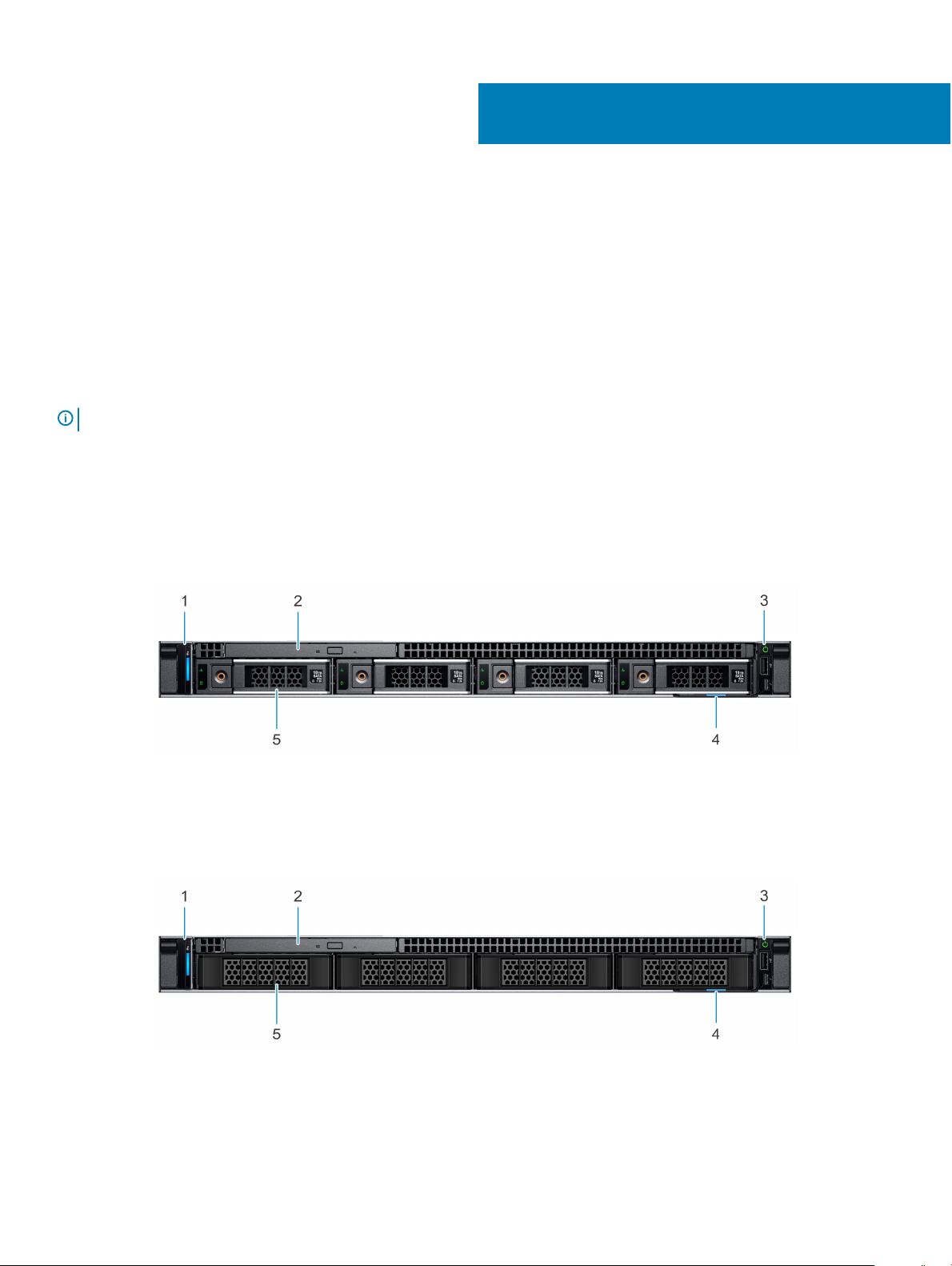
Front view of the system
1
Figure 1. Front view of the 4 x 3.5-inch drive system
1
Left control panel 2 Optical drive (optional)
3 Right control panel 4 Information tag
5 Drive (4)
Figure 2. Front view of the 4 x 3.5-inch cabled drive system
Left control panel 2 Optical drive (optional)
1
Dell EMC PowerEdge R240 system overview 5
Page 6
3 Right control panel 4 Information tag
5 Drive (4)
NOTE: LED functionality is not supported on cabled disk drive conguration.
For more information about the ports, see the Technical Specications section.
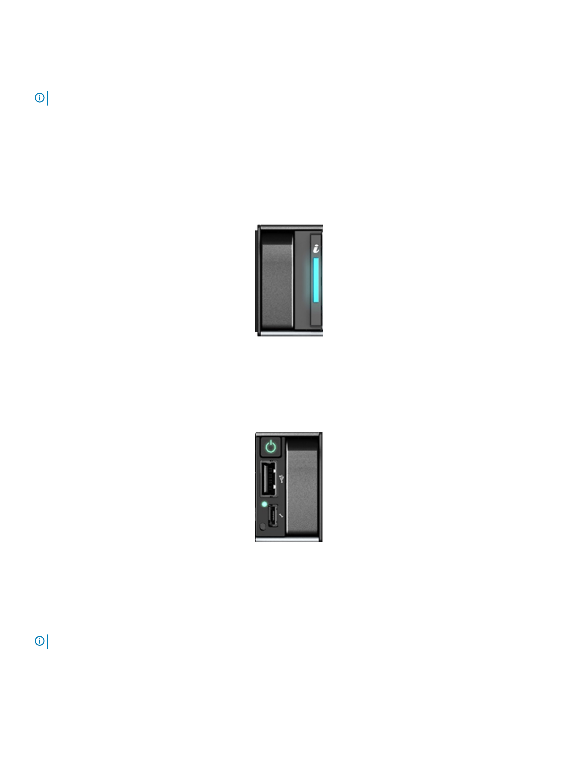
Control panels
Left control panel view
Figure 3. Left control panel view
• System health and system ID indicator
Right control panel view
Figure 4. Right control panel view
• Power button
• USB 2.0-compliant port
• iDRAC LED indicator
• Micro USB 2.0-compliant port for iDRAC Direct
: For more information on the ports, see the Ports and connectors specications section.
NOTE
6 Dell EMC PowerEdge R240 system overview
Page 7
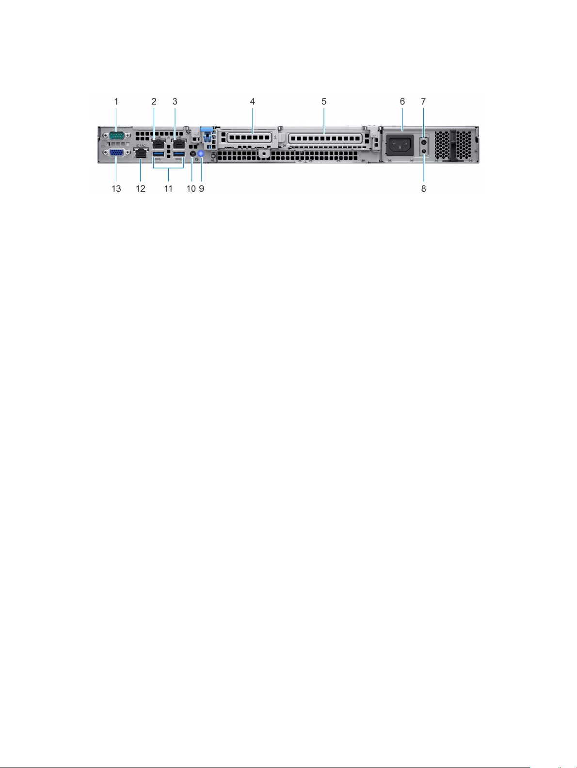
Rear view of the system
Figure 5. Rear view of the system
1 Serial port 2 NIC port (Gb 1)
3 NIC port (Gb 2) 4 Half-height PCIe expansion card slot
5 Full-height PCIe expansion card slot 6 Power supply unit
7 PSU Built-in Self Test (BIST) LED 8 PSU Built-in Self Test (BIST) button
9 System identication button 10 System status indicator cable port (CMA)
11 USB 3.0 ports (2) 12 iDRAC dedicated NIC port
13 VGA port
For more information about the ports and connectors, see the Technical Specications section.
Dell EMC PowerEdge R240 system overview
7
Page 8

Technical specications
The technical and environmental specications of your system are outlined in this section.
Topics:
• Chassis dimensions
• System weight
• Processor specications
• PSU specications
• Cooling fans specications
• System battery specications
• Expansion card riser specications
• Memory specications
• Storage controller specications
• Drive specications
• Ports and connectors specications
• Video specications
• Environmental specications
2
8 Technical specications
Page 9
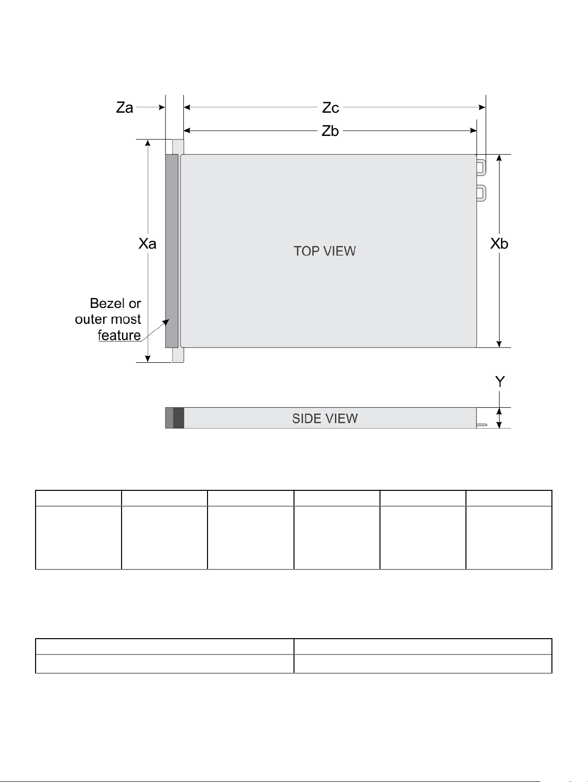
Chassis dimensions
Figure 6. Chassis dimensions
Table 1.
Dell EMC PowerEdge R240 chassis dimensions
Xa Xb Y Za Zb Zc
482.0 mm
(18.97 inches)
434.0 mm
(17.08 inches)
42.8 mm
(1.68 inches)
With bezel: 35.64
mm (1.4 inches)
Without bezel: 22.0
mm (0.87 inches)
534.496 mm
(21.04 inches)
System weight
Table 2.
Dell EMC PowerEdge R240 system weight
System conguration Maximum weight (with all drives/SSDs)
4 x 3.5-inch drives 12.2 kg (26.89 lb)
573.596 mm
(22.58 inches)
Technical specications 9
Page 10

Processor specications
Table 3. Dell EMC PowerEdge R240 processor specications
Supported processor Number of processors supported
Intel Xeon Scalable Processor One
PSU specications
The Dell EMC PowerEdge R240 system supports a cabled AC power supply unit (PSU).
Table 4. Dell EMC PowerEdge R240 PSU specications
Heat
PSU Class
250 W AC Bronze 1039 BTU/hr
NOTE: This system is also designed to connect to the IT power systems with a phase-to-phase voltage not exceeding 230 V.
dissipation
(maximum) Frequency Voltage
50/60 Hz
100-240 V
AC,autoranging
High line 100–
240 V
250 W N/A 4.0A-2.0 A
AC
Low line 100–
120 V
Current
Cooling fans specications
The Dell EMC PowerEdge R240 system supports the following cooling fans.
NOTE
: When selecting or upgrading the system conguration, to ensure optimum power utilization, verify the system power
consumption with the Dell Energy Smart Solution Advisor available at Dell.com/ESSA.
Table 5. Dell EMC PowerEdge R240 fan support matrix
Front storage Fan 1 Fan 2 Fan 3 Fan 4
Max allowable 3.5-inch
drive counts = 2
Max allowable 3.5-inch
drive counts = 4
Required when PCIe is
installed
Required when PCIe is
installed
Required Required N/A
Required Required Required
System battery specications
The Dell EMC PowerEdge R240 system supports CR 2032 3.0-V lithium coin cell system battery.
Expansion card riser specications
The Dell EMC PowerEdge R240 system supports up to two PCI express (PCIe) generation 3.
Technical specications
10
Page 11
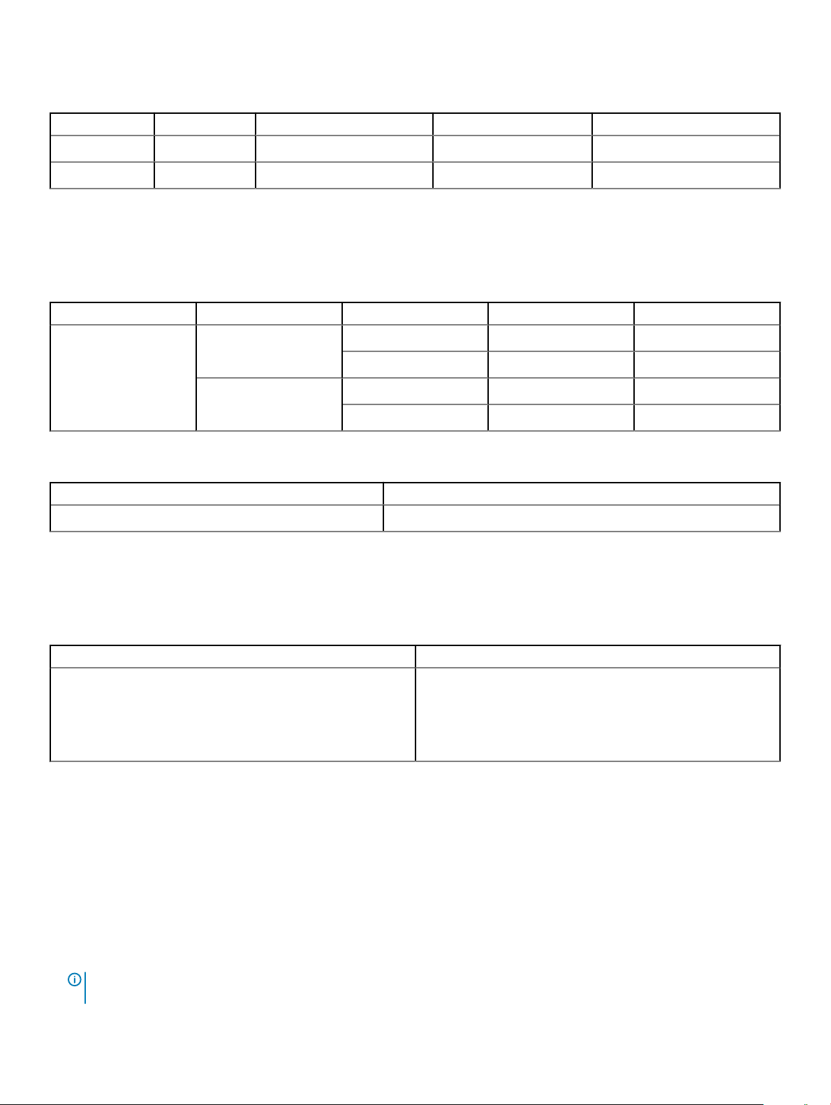
Table 6. Expansion card slots supported on the system board
PCIe slot Riser PCIe slot height PCIe slot length Slot width
Slot 1 x8 PCIe Low-prole Half-length x8
Slot 2 x16 PCIe Low-prole/Full-height Half-length x16
Memory specications
The PowerEdge R240 system supports the following memory specications for optimized operation.
Table 7. Memory specications
DIMM type DIMM rank DIMM capacity Minimum RAM Maximum RAM
Single rank
UDIMM
Dual rank
Table 8. Memory module sockets
Memory module sockets Speed
Four 288-pin 2666 MT/s
8 GB 8 GB 32 GB
16 GB 16 GB 64 GB
8 GB 8 GB 32 GB
16 GB 16 GB 64 GB
Storage controller specications
The Dell EMC PowerEdge R240 system supports the following controller cards:
Table 9.
Dell EMC PowerEdge R240 system controller cards
Internal controllers External controllers
• PERC H730P
• PERC H330
• S140
• HBA330
• 12Gbps SAS Ext. HBA
Drive specications
Drives
The Dell EMC PowerEdge R240 system supports:
• 4 x 3.5-inch hot-swappable SAS, SATA, or SSD
• 4 x 3.5-inch cabled drives
• 2 x 3.5-inch cabled drives
: LED functionality is not supported on cabled hard disk drive
NOTE
conguration.
Technical specications 11
Page 12
Backplane:
• Up to 4 x 3.5-inch SAS, SATA drives, or SSD drives
• Up to 4 x 2.5-inch SAS, SATA drives, or SSD drives
Optical drives
The Dell EMC PowerEdge R240 system supports the following optical drives.
Table 10. Supported optical drive type
Supported drive type Supported number of drives
Dedicated SATA DVD-ROM drive or DVD +/-RW drive One
Ports and connectors specications
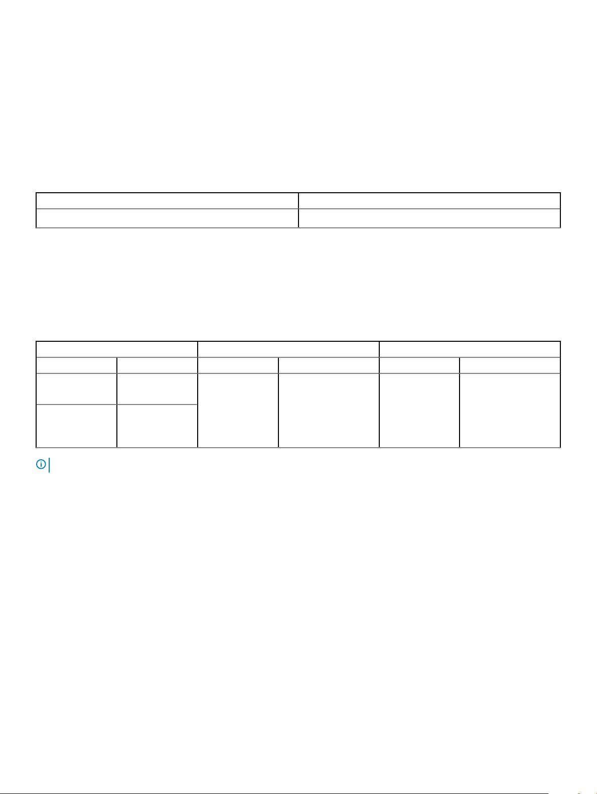
USB ports specications
Table 11. Dell EMC PowerEdge R240 system USB specications
Front Rear Internal
USB port type No. of ports USB port type No. of ports USB port type No. of ports
USB 2.0-compliant
port
Micro USB 2.0compliant port for
iDRAC Direct
NOTE: The micro USB 2.0 compliant port can only be used as an iDRAC Direct or a management port.
One USB 3.0-compliant
ports
One
Two Internal USB 3.0-
compliant port
One
NIC ports specications
The Dell EMC PowerEdge R240 system supports up to two 10/100/1000 Mbps Network Interface Controller (NIC) ports that are located
on the back panel.
Serial connector specications
The Dell EMC PowerEdge R240 system supports one serial connector on the back panel, which is a 9-pin connector, Data Terminal
Equipment (DTE), 16550-compliant.
VGA ports specications
The Dell EMC PowerEdge R240 system supports DB-15 VGA connector.
Technical specications
12
Page 13

Video specications
The Dell EMC PowerEdge R240 system supports integrated Matrox G200 graphics controller with 16 MB of video frame buer.
Table 12. Supported video resolution options
Resolution Refresh rate (Hz) Color depth (bits)
640 x 480 60, 72 8, 16, 24
800 x 600 60, 75, 85 8, 16, 24
1024 x 768 60, 75, 85 8, 16, 24
1152 x 864 60, 75, 85 8, 16, 24
1280 x 1024 60, 75 8, 16, 24
Environmental specications
NOTE: For additional information about environmental certications, refer to the
the Manuals & Documents on Dell.com/support/home.
Table 13. Temperature specications
Temperature Specications
Storage -40–65°C (-40–149°F)
Continuous operation (for altitude less than 950 m or
3117 ft)
Fresh air For information about fresh air, see the Expanded operating temperature section.
Maximum temperature gradient (operating and
storage)
Table 14. Relative humidity specications
Relative humidity Specications
Storage 5% to 95% RH with 33°C (91°F) maximum dew point.
Operating 10% to 80% RH with 29°C (84.2°F) maximum dew point.
10–35°C (50–95°F) with no direct sunlight on the equipment
20°C/h (36°F/h)
Atmosphere must be noncondensing at all times.
Product Environmental Datasheet
located with
Table 15. Maximum vibration specications
Maximum vibration Specications
Operating 0.26 G
Storage 1.88 G
at 5 Hz to 350 Hz (all operation orientations)
rms
at 10 Hz to 500 Hz for 15 minutes (all six sides tested)
rms
Technical specications 13
Page 14

Table 16. Maximum shock pulse specications
Maximum shock pulse Specications
Operating Six consecutively executed shock pulses in the positive and negative x, y, and z
axis of 6 G for up to 11 ms.
Storage Six consecutively executed shock pulses in the positive and negative x, y, and z
axis (one pulse on each side of the system) of 71 G for up to 2 ms.
Table 17. Maximum altitude specications
Maximum altitude Specications
Operating 3048 m (10,000 ft)
Storage 12,000 m (39,370 ft)
Table 18. Operating temperature derating specications
Operating temperature derating Specications
Up to 35°C (95°F) Maximum temperature is reduced by 1°C/300 m (1°F/547 ft), above 950 m (3,117
ft).
35–40°C (95–104°F) Maximum temperature is reduced by 1°C/175 m (1°F/319 ft), above 950 m (3,117
ft).
40–45°C (104–113°F) Maximum temperature is reduced by 1°C/125 m (1°F/228 ft), above 950 m (3,117
ft).
Standard operating temperature
Table 19. Standard operating temperature
Standard operating temperature Specications
Continuous operation (for altitude less than 950 m or 3117
ft)
specications
10–35°C (50–95°F) with no direct sunlight on the equipment.
Expanded operating temperature
Table 20. Expanded operating temperature
Expanded operating temperature Specications
Continuous operation 5°C–40°C at 5% to 85% RH with 29°C dew point.
specications
NOTE: Outside the standard operating temperature
(10°C–35°C), the system can operate continuously in
temperatures as low as 5°C and as high as 40°C.
14 Technical specications
Page 15
Expanded operating temperature Specications
For temperatures 35°C– 40°C, derate maximum allowable
temperature by 1°C per 175 m (1°F per 319 ft) above 950 m (3,1171
ft).
≤ 1% of annual operating hours -5°C–45°C at 5% to 90% RH with 29°C dew point.
NOTE: Outside the standard operating temperature
(10°C–35°C), the system can operate down to -5°C or
up to 45°C for a maximum of 1% of its annual operating
hours.
For temperatures 40°C– 45°C, derate maximum allowable
temperature by 1°C per 125 m (1°F per 228 ft) above 950 m (3.117
ft).
NOTE: When operating in the expanded temperature range, the performance of the system may be impacted.
NOTE: When operating in the expanded temperature range, ambient temperature warnings may be reported on the System
Event Log.
Expanded operating temperature restrictions
• Do not perform a cold startup of the system below 5°C.
• The operating temperature specied is for a maximum altitude of 950m for fresh air cooling.
• Four system fans are required.
• Support for up to 71W processor.
• GPU is not supported.
• Non-Dell qualied peripheral cards and/or peripheral cards greater than 25 W are not supported.
Particulate and gaseous contamination specications
The following table denes the limitations that help avoid any damages to the IT equipment and/or, or both failure from particulate and
gaseous contamination. If the levels of particulate or gaseous pollution exceed the specied limitations and results in equipment damage or
failure, you must rectify the environmental conditions. Remediation of environmental conditions is the responsibility of the customer.
Table 21. Particulate contamination
Particulate contamination Specications
Air ltration
Conductive dust Air must be free of conductive dust, zinc whiskers, or other
specications
Data center air ltration as dened by ISO Class 8 per ISO 14644-1
with a 95% upper condence limit.
NOTE: This condition applies to data center environments
only. Air ltration requirements do not apply to IT
equipment designed to be used outside a data center, in
environments such as an oce or factory oor.
NOTE: Air entering the data center must have MERV11 or
MERV13 ltration.
conductive particles.
Technical specications 15
Page 16

Particulate contamination Specications
NOTE: This condition applies to data center and non-data
center environments.
Corrosive dust
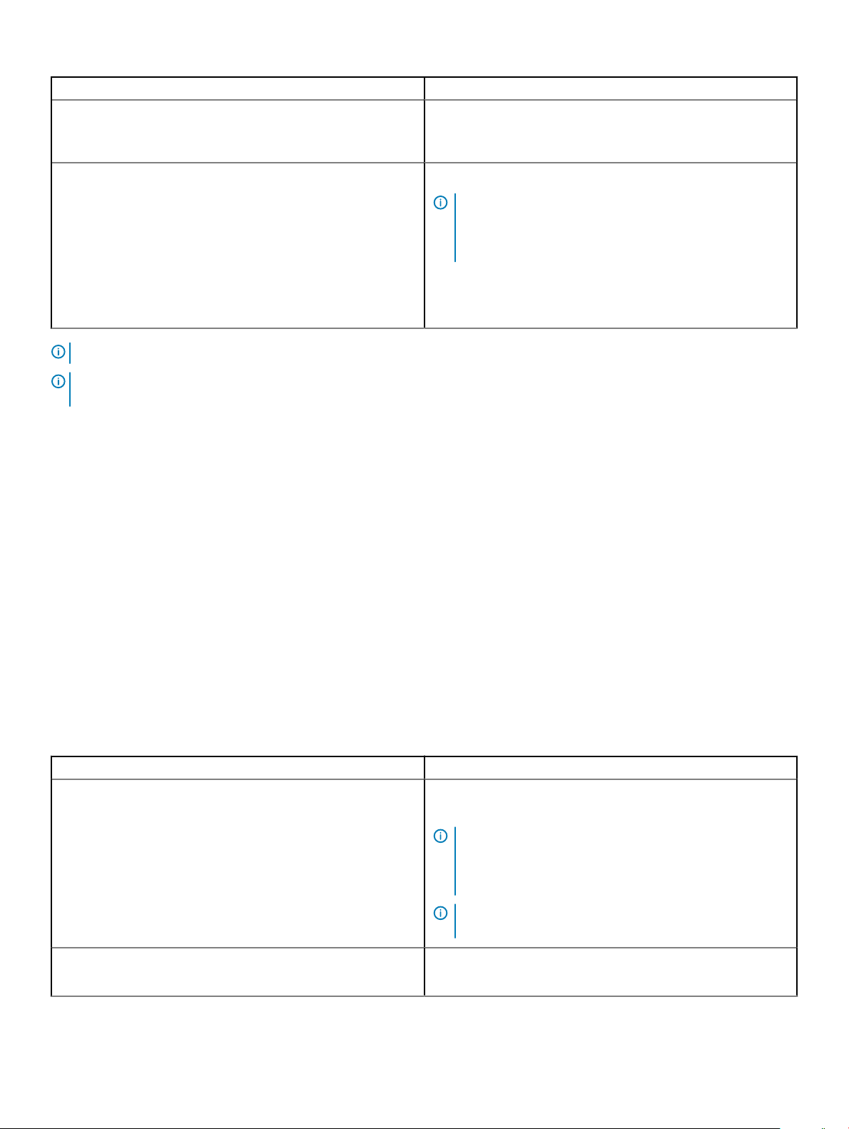
Table 22. Gaseous contamination specications
Gaseous contamination Specications
Copper Coupon Corrosion <300 Å/month per Class G1 as dened by ANSI/ISA71.04-1985.
Silver Coupon Corrosion <200 Å/month as dened by AHSRAE TC9.9.
NOTE: Maximum corrosive contaminant levels measured at ≤50% relative humidity.
• Air must be free of corrosive dust.
• Residual dust present in the air must have a deliquescent point
less than 60% relative humidity.
NOTE: This condition applies to data center and non-data
center environments.
16 Technical specications
Page 17

System diagnostics and indicator codes
The diagnostic indicators on the system front panel display system status during system startup.
Topics:
• System health and system ID indicator codes
• iDRAC Direct LED indicator codes
• NIC indicator codes
• Non-redundant cabled power supply unit indicator codes
• Drive indicator codes
System health and system ID indicator codes
The system health and system ID indicator is located on the left control panel of your system.
3
Figure 7. System health and system ID indicator
System diagnostics and indicator codes 17
Page 18
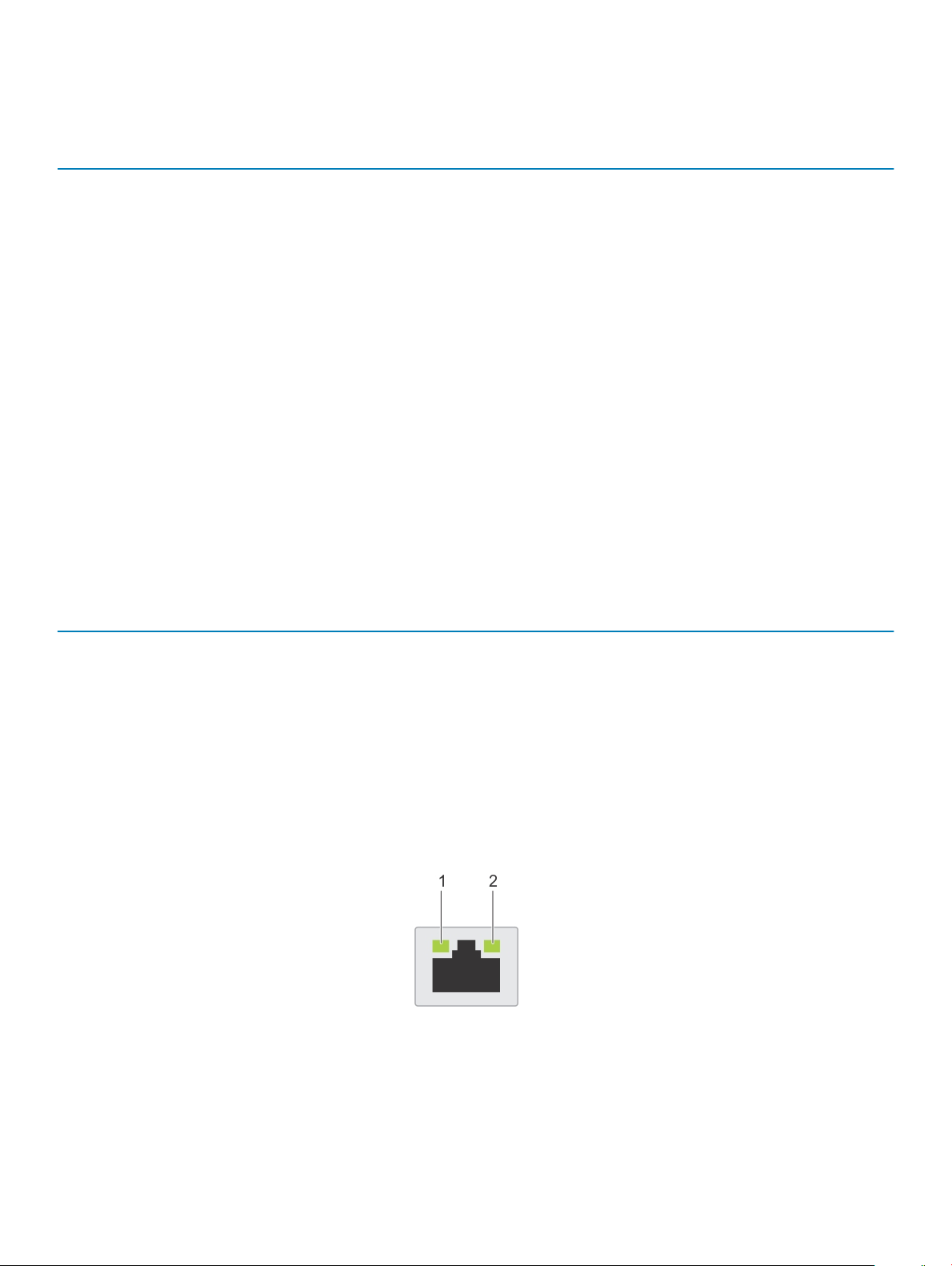
Table 23. System health and system ID indicator codes
System health and system ID indicator
code
Solid blue Indicates that the system is turned on, system is healthy, and system ID mode is not active.
Blinking blue Indicates that the system ID mode is active. Press the system health and system ID button to
Solid amber Indicates that the system is in fail-safe mode. If the problem persists, see the Getting help
Blinking amber Indicates that the system is experiencing a fault. Check the System Event Log for specic
Condition
Press the system health and system ID button to switch to system ID mode.
switch to system health mode.
section.
error messages. For information about the event and error messages generated by the system
rmware and agents that monitor system components, see the Error Code Lookup page, at
qrl.dell.com
iDRAC Direct LED indicator codes
The iDRAC Direct LED indicator lights up to indicate that the port is connected and is being used as a part of the iDRAC subsystem.
You can congure iDRAC Direct by using a USB to micro USB (type AB) cable, which you can connect to your laptop or tablet. The
following table describes iDRAC Direct activity when the iDRAC Direct port is active:
Table 24. iDRAC Direct LED indicator codes
iDRAC Direct LED
indicator code
Condition
Solid green for two seconds Indicates that the laptop or tablet is connected.
Flashing green (on for two
seconds and o for two
seconds)
Powers o Indicates that the laptop or tablet is unplugged.
Indicates that the laptop or tablet connected is recognized.
NIC indicator codes
Each NIC on the back of the system has indicators that provide information about the activity and link status. The activity LED indicator
indicates if data is owing through the NIC, and the link LED indicator indicates the speed of the connected network.
Figure 8. NIC indicator codes
Link LED indicator 2 Activity LED indicator
1
18 System diagnostics and indicator codes
Page 19

Table 25. NIC indicator codes
Status Condition
Link and activity indicators are o. The NIC is not connected to the network.
Link indicator is green, and activity indicator is blinking
green.
Link indicator is amber, and activity indicator is blinking
green.
Link indicator is green, and activity indicator is o. The NIC is connected to a valid network at its maximum port speed, and
Link indicator is amber, and activity indicator is o. The NIC is connected to a valid network at less than its maximum port
Link indicator is blinking green, and activity is o. NIC identify is enabled through the NIC conguration utility.
The NIC is connected to a valid network at its maximum port speed, and
data is being sent or received.
The NIC is connected to a valid network at less than its maximum port
speed, and data is being sent or received.
data is not being sent or received.
speed, and data is not being sent or received.
Non-redundant cabled power supply unit indicator codes
Press the self-diagnostic button to perform a quick health check on the non-redundant cabled power supply unit (PSU) of the system.
Figure 9. Non-redundant cabled AC PSU status indicator and self-diagnostic button
1
Self-diagnostic button 2 AC PSU status indicator
Table 26. Non-redundant AC PSU status indicator
Power Indicator Pattern Condition
Not lit Power is not connected or PSU is faulty.
Green A valid power source is connected to the PSU and the PSU is operational.
System diagnostics and indicator codes 19
Page 20

Drive indicator codes
The LEDs on the drive carrier indicates the state of each drive. Each drive carrier in your system has two LEDs: an activity LED (green) and
a status LED (bicolor, green/amber). The activity LED ashes whenever the drive is accessed.
Figure 10. Drive indicators
1 Drive activity LED indicator 2 Drive status LED indicator
3 Drive capacity label
NOTE: If the drive is in the Advanced Host Controller Interface (AHCI) mode, the status LED indicator does not turn on.
Table 27. Drive indicator codes
Drive status indicator code Condition
Flashes green twice per second Identifying drive or preparing for removal.
O Drive ready for removal.
NOTE: The drive status indicator remains o until all drives are
initialized after the system is turned on. Drives are not ready
for removal during this time.
Flashes green, amber, and then turns o Predicted drive failure.
Flashes amber four times per second Drive failed.
Flashes green slowly Drive rebuilding.
Solid green Drive online.
Flashes green for three seconds, amber for three seconds, and
then turns o after six seconds
Rebuild stopped.
20 System diagnostics and indicator codes
Page 21

Getting help
Topics:
• Recycling or End-of-Life service information
• Contacting Dell
• Accessing system information by using QRL
• Receiving automated support with SupportAssist
Recycling or End-of-Life service information
Take back and recycling services are oered for this product in certain countries. If you want to dispose of system components, visit
Dell.com/recyclingworldwide and select the relevant country.
Contacting Dell
Dell provides several online and telephone based support and service options. If you do not have an active internet connection, you can nd
contact information about your purchase invoice, packing slip, bill, or Dell product catalog. Availability varies by country and product, and
some services may not be available in your area. To contact Dell for sales, technical assistance, or customer service issues:
4
1 Go to Dell.com/support/home
2 Select your country from the drop-down menu on the lower right corner of the page.
3 For customized support:
a Enter your system Service Tag in the Enter your Service Tag eld.
b Click Submit.
The support page that lists the various support categories is displayed.
4 For general support:
a Select your product category.
b Select your product segment.
c Select your product.
The support page that lists the various support categories is displayed.
5 For contact details of Dell Global Technical Support:
a Click Global Technical Support
b The Contact Technical Support page is displayed with details to call, chat, or e-mail the Dell Global Technical Support team.
Accessing system information by using QRL
Prerequisites
Ensure that your smartphone or tablet has the QR code scanner installed.
The QRL includes the following information about your system:
• How-to videos
• Reference materials, including the Installtion and Service Manual, and mechanical overview
• Your system service tag to quickly access your specic hardware conguration and warranty information
• A direct link to Dell to contact technical assistance and sales teams
Getting help 21
Page 22
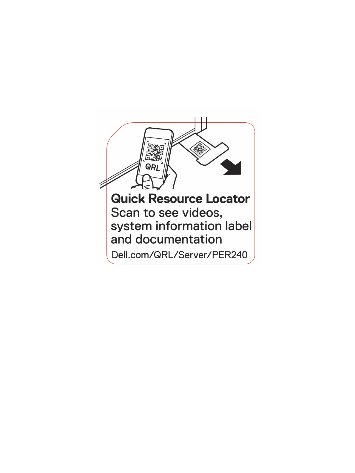
Steps
1 Go to Dell.com/qrl and navigate to your specic product or
2 Use your smartphone or tablet to scan the model-specic Quick Resource (QR) code on your system or in the Quick Resource
Locator section.
Quick Resource Locator for Dell EMC PowerEdge R240 system
Figure 11. Quick Resource Locator for Dell EMC PowerEdge R240 system
Receiving automated support with SupportAssist
Dell EMC SupportAssist is an optional Dell EMC Services oering that automates technical support for your Dell EMC server, storage, and
networking devices. By installing and setting up a SupportAssist application in your IT environment, you can receive the following benets:
• Automated issue detection — SupportAssist monitors your Dell EMC devices and automatically detects hardware issues, both
proactively and predictively.
• Automated case creation — When an issue is detected, SupportAssist automatically opens a support case with Dell EMC Technical
Support.
• Automated diagnostic collection — SupportAssist automatically collects system state information from your devices and uploads it
securely to Dell EMC. This information is used by Dell EMC Technical Support to troubleshoot the issue.
• Proactive contact — A Dell EMC Technical Support agent contacts you about the support case and helps you resolve the issue.
The available benets vary depending on the Dell EMC Service entitlement purchased for your device. For more information about
SupportAssist, go to Dell.com/supportassist.
Getting help
22
Page 23

5
Safety instructions
WARNING: Whenever you need to lift the system, get others to assist you. To avoid injury, do not attempt to lift the system by
yourself.
WARNING: Opening or removing the system cover while the system is powered on may expose you to a risk of electric shock.
CAUTION: Do not operate the system without the cover for a duration exceeding ve minutes.
CAUTION: Many repairs may only be done by a certied service technician. You should only perform troubleshooting and simple
repairs as authorized in your product documentation, or as directed by the online or telephone service and support team.
Damage due to servicing that is not authorized by Dell is not covered by your warranty. Read and follow the safety instructions
that are shipped with your product.
NOTE: It is recommended that you always use an antistatic mat and antistatic strap while working on components inside the
system.
NOTE: To ensure proper operation and cooling, all bays in the system and system fans must be populated always with either a
component or with a blank.
Safety instructions 23
 Loading...