

Page 1

Dell EMC PowerEdge R240
Installation and Service Manual
Regulatory Model: E57S Series
Regulatory Type: E57S001
Page 2

Notes, cautions, and warnings
NOTE: A NOTE indicates important information that helps you make better use of your product.
CAUTION: A CAUTION indicates either potential damage to hardware or loss of data and tells you how to avoid the problem.
WARNING: A WARNING indicates a potential for property damage, personal injury, or death.
© 2018 Dell Inc. or its subsidiaries. All rights reserved. Dell, EMC, and other trademarks are trademarks of Dell Inc. or its subsidiaries. Other trademarks
may be trademarks of their respective owners.
2018 - 12
Rev. A00
Page 3

Contents
1 About this document...................................................................................................................................... 7
2 Dell EMC PowerEdge R240 system overview................................................................................................ 8
Front view of the system.................................................................................................................................................. 8
Control panels...............................................................................................................................................................9
Rear view of the system..................................................................................................................................................10
Inside the system...............................................................................................................................................................11
Locating the information tag of your system................................................................................................................ 12
3 Initial system setup and conguration...........................................................................................................14
Setting up your system....................................................................................................................................................14
iDRAC conguration.........................................................................................................................................................14
Options to set up iDRAC IP address.........................................................................................................................14
Log in to iDRAC...........................................................................................................................................................15
Options to install the operating system......................................................................................................................... 15
Methods to download rmware and drivers........................................................................................................... 15
Downloading drivers and rmware........................................................................................................................... 16
4 Pre-operating system management applications...........................................................................................17
Options to manage the pre-operating system applications.........................................................................................17
System Setup....................................................................................................................................................................17
Viewing System Setup............................................................................................................................................... 17
System Setup details..................................................................................................................................................18
System BIOS............................................................................................................................................................... 18
iDRAC Settings utility................................................................................................................................................36
Device Settings..........................................................................................................................................................36
Dell Lifecycle Controller...................................................................................................................................................36
Embedded system management............................................................................................................................. 36
Boot Manager...................................................................................................................................................................37
Viewing Boot Manager..............................................................................................................................................37
Boot Manager main menu.........................................................................................................................................37
One-shot UEFI boot menu........................................................................................................................................37
System Utilities...........................................................................................................................................................37
PXE boot...........................................................................................................................................................................37
5 Installing and removing system components................................................................................................39
Safety instructions...........................................................................................................................................................39
Before working inside your system................................................................................................................................39
After working inside your system...................................................................................................................................39
Recommended tools........................................................................................................................................................40
Front bezel........................................................................................................................................................................40
Removing the front bezel......................................................................................................................................... 40
Contents
3
Page 4

Installing the front bezel.............................................................................................................................................41
System cover....................................................................................................................................................................42
Removing the system cover.....................................................................................................................................42
Installing the system cover....................................................................................................................................... 43
Air shroud..........................................................................................................................................................................44
Removing the air shroud...........................................................................................................................................44
Installing the air shroud............................................................................................................................................. 45
Cooling fans......................................................................................................................................................................46
Removing the cooling fan blank...............................................................................................................................46
Installing the cooling fan blank................................................................................................................................. 46
Removing a cooling fan............................................................................................................................................. 47
Installing a cooling fan............................................................................................................................................... 48
Drives.................................................................................................................................................................................49
Removing a drive blank............................................................................................................................................. 49
Installing a drive blank............................................................................................................................................... 50
Removing a hot-swappable drive............................................................................................................................ 50
Installing the hot-swappable drive............................................................................................................................51
Removing the drive from the drive carrier..............................................................................................................52
Installing the drive into the drive carrier..................................................................................................................53
Removing a 2.5-inch drive from a 3.5-inch drive adapter.................................................................................... 54
Installing a 2.5-inch drive into a 3.5-inch drive adapter........................................................................................ 55
Removing a 3.5-inch drive adapter from a 3.5-inch drive carrier........................................................................ 56
Installing a 3.5-inch adapter into a 3.5-inch drive carrier......................................................................................57
Removing a cabled drive...........................................................................................................................................58
Installing a cabled drive............................................................................................................................................. 59
Removing the cabled drive from the drive carrier.................................................................................................60
Installing a cabled drive into the drive carrier..........................................................................................................61
Intrusion switch................................................................................................................................................................62
Removing the intrusion switch.................................................................................................................................62
Installing the intrusion switch...................................................................................................................................63
System memory...............................................................................................................................................................63
System memory guidelines.......................................................................................................................................64
General memory module installation guidelines......................................................................................................65
Removing a memory module....................................................................................................................................66
Installing a memory module...................................................................................................................................... 66
Expansion cards and expansion card risers...................................................................................................................67
Expansion card installation guidelines......................................................................................................................68
Removing the expansion card riser..........................................................................................................................69
Installing the expansion card riser............................................................................................................................70
Removing expansion card from the expansion card riser......................................................................................72
Installing expansion card into the expansion card riser..........................................................................................73
M.2 SSD module.............................................................................................................................................................. 75
Removing the M.2 SSD module...............................................................................................................................75
Installing the M.2 SSD module................................................................................................................................. 75
System battery ................................................................................................................................................................76
Contents
4
Page 5

Replacing the system battery...................................................................................................................................76
Optional internal USB memory key................................................................................................................................78
Replacing the optional internal USB memory key.................................................................................................. 79
Optional optical drive.......................................................................................................................................................79
Removing the optional optical drive.........................................................................................................................79
Installing the optional optical drive...........................................................................................................................80
Processor and heat sink...................................................................................................................................................81
Removing the heat sink............................................................................................................................................. 81
Removing the processor...........................................................................................................................................82
Installing the processor............................................................................................................................................. 83
Installing the heat sink...............................................................................................................................................84
Optional IDSDM or vFlash module.................................................................................................................................85
Removing the optional IDSDM or vFlash card.......................................................................................................85
Installing optional IDSDM or vFlash card.................................................................................................................85
Removing the MicroSD card.................................................................................................................................... 86
Installing the MicroSD card....................................................................................................................................... 87
Drive backplane................................................................................................................................................................88
Drive backplane..........................................................................................................................................................88
Removing the drive backplane.................................................................................................................................89
Installing the drive backplane................................................................................................................................... 89
Cable routing.....................................................................................................................................................................91
Power supply unit.............................................................................................................................................................93
Removing a cabled power supply unit.....................................................................................................................93
Installing a cabled power supply unit.......................................................................................................................94
System board................................................................................................................................................................... 95
Removing the system board.....................................................................................................................................95
Installing the system board....................................................................................................................................... 97
Restoring the system using Easy Restore.............................................................................................................. 99
Trusted Platform Module................................................................................................................................................ 99
Upgrading the Trusted Platform Module................................................................................................................ 99
Initializing TPM for BitLocker users....................................................................................................................... 100
Initializing the TPM 1.2 for TXT users.....................................................................................................................101
Initializing the TPM 2.0 for TXT users....................................................................................................................101
Control panel....................................................................................................................................................................101
Removing the left control panel.............................................................................................................................. 101
Installing the left control panel................................................................................................................................102
Removing the right control panel........................................................................................................................... 103
Installing the right control panel............................................................................................................................. 104
6 Jumpers and connectors ........................................................................................................................... 106
System board connectors..............................................................................................................................................107
System board jumper settings...................................................................................................................................... 108
Disabling forgotten password........................................................................................................................................108
7 Technical specications.............................................................................................................................. 110
Chassis dimensions..........................................................................................................................................................111
Contents
5
Page 6

System weight..................................................................................................................................................................111
Processor specications.................................................................................................................................................112
PSU specications.......................................................................................................................................................... 112
Cooling fans specications.............................................................................................................................................112
System battery specications........................................................................................................................................112
Expansion card riser specications...............................................................................................................................112
Memory specications....................................................................................................................................................113
Storage controller specications...................................................................................................................................113
Drive specications.........................................................................................................................................................113
Drives..........................................................................................................................................................................113
Optical drives.............................................................................................................................................................114
Ports and connectors specications.............................................................................................................................114
USB ports specications..........................................................................................................................................114
NIC ports specications........................................................................................................................................... 114
Serial connector specications................................................................................................................................114
VGA ports specications..........................................................................................................................................114
IDSDM module...........................................................................................................................................................115
Video specications........................................................................................................................................................ 115
Environmental specications......................................................................................................................................... 115
Standard operating temperature............................................................................................................................. 117
Expanded operating temperature............................................................................................................................117
Particulate and gaseous contamination specications.........................................................................................118
8 System diagnostics and indicator codes .....................................................................................................119
System health and system ID indicator codes.............................................................................................................119
iDRAC Direct LED indicator codes............................................................................................................................... 120
NIC indicator codes........................................................................................................................................................120
Non-redundant cabled power supply unit indicator codes.........................................................................................121
Drive indicator codes......................................................................................................................................................122
Using system diagnostics.............................................................................................................................................. 122
Dell Embedded System Diagnostics.......................................................................................................................122
9 Getting help............................................................................................................................................... 124
Recycling or End-of-Life service information..............................................................................................................124
Contacting Dell................................................................................................................................................................124
Accessing system information by using QRL..............................................................................................................124
Quick Resource Locator for Dell EMC PowerEdge R240 system......................................................................125
Receiving automated support with SupportAssist ....................................................................................................125
10 Documentation resources......................................................................................................................... 126
Contents
6
Page 7

About this document
This document provides an overview about the system, information about installing and replacing components, technical specications,
diagnostic tools, and guidelines to be followed while installing certain components.
1
About this document 7
Page 8
Dell EMC PowerEdge R240 system overview
The Dell EMC PowerEdge R240 system is a 1U server that supports:
• One Intel Xeon Scalable processor
• Four DIMM slots
• Cabled AC power supply unit
• Up to four 3.5-inch SAS, SATA drives or SSDs, or four 3.5-inch cabled drives, or two 3.5-inch cabled drives.
For more information about supported drives, see the Drive specications section.
NOTE: All instances of SAS, SATA drives, and SSDs are referred to as drives in this document, unless specied otherwise.
Topics:
• Front view of the system
• Rear view of the system
• Inside the system
• Locating the information tag of your system
2
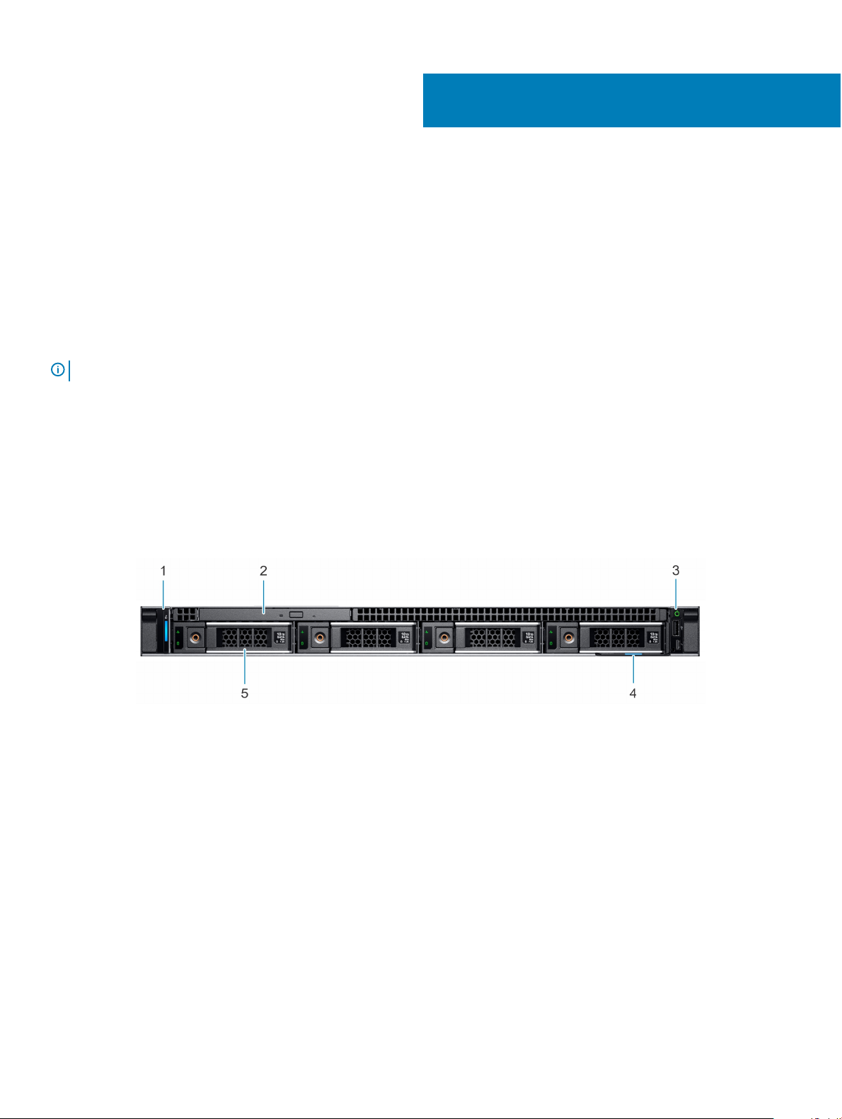
Front view of the system
Figure 1. Front view of the 4 x 3.5-inch drive system
1
Left control panel 2 Optical drive (optional)
3 Right control panel 4 Information tag
5 Drive (4)
8 Dell EMC PowerEdge R240 system overview
Page 9
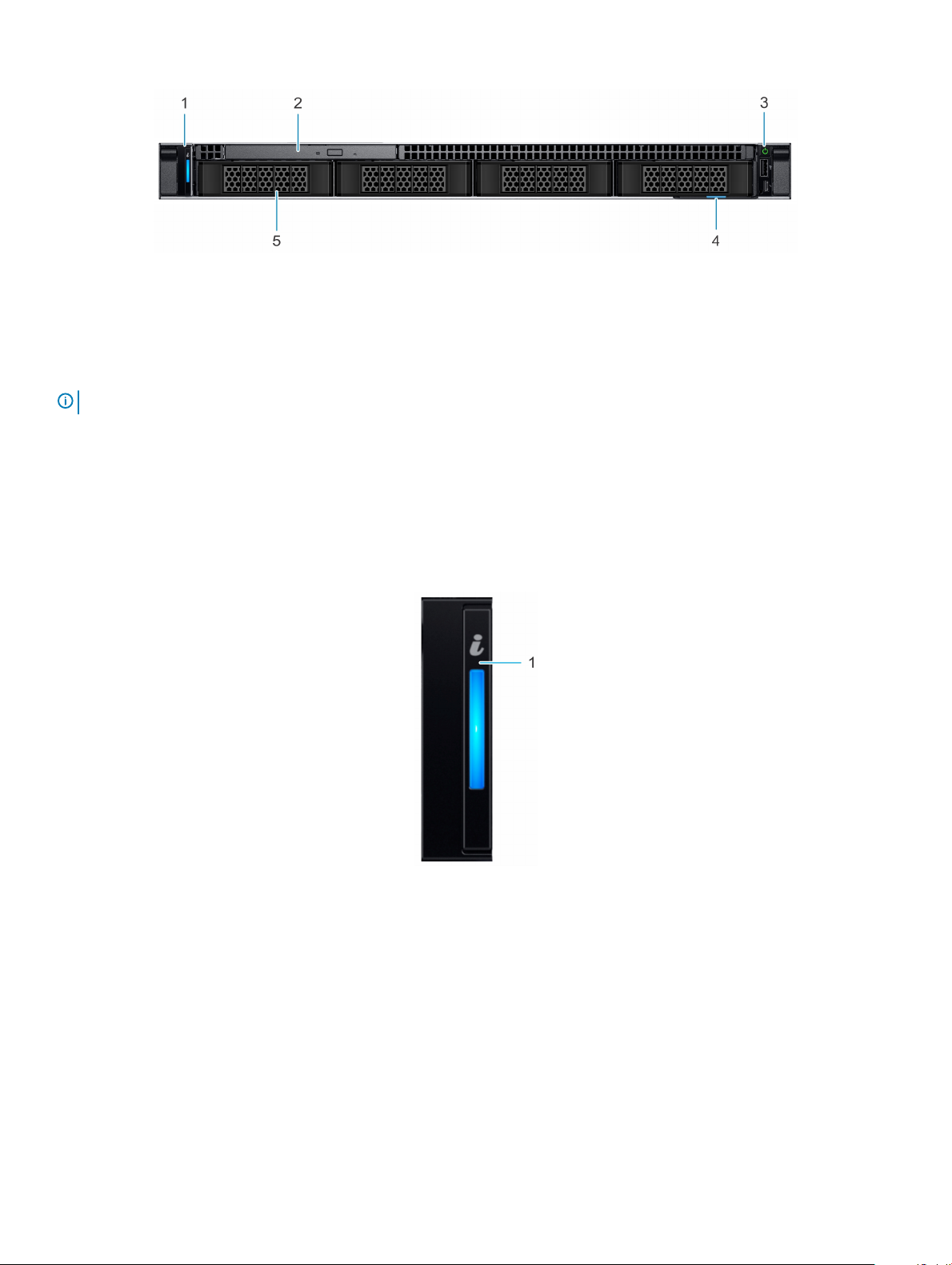
Figure 2. Front view of the 4 x 3.5-inch cabled drive system
1 Left control panel 2 Optical drive (optional)
3 Right control panel 4 Information tag
5 Drive (4)
NOTE: LED functionality is not supported on cabled disk drive conguration.
For more information about the ports, see the Technical Specications section.
Control panels
Left control panel
Figure 3. Left control panel view
1
System health and system ID indicator
Dell EMC PowerEdge R240 system overview 9
Page 10
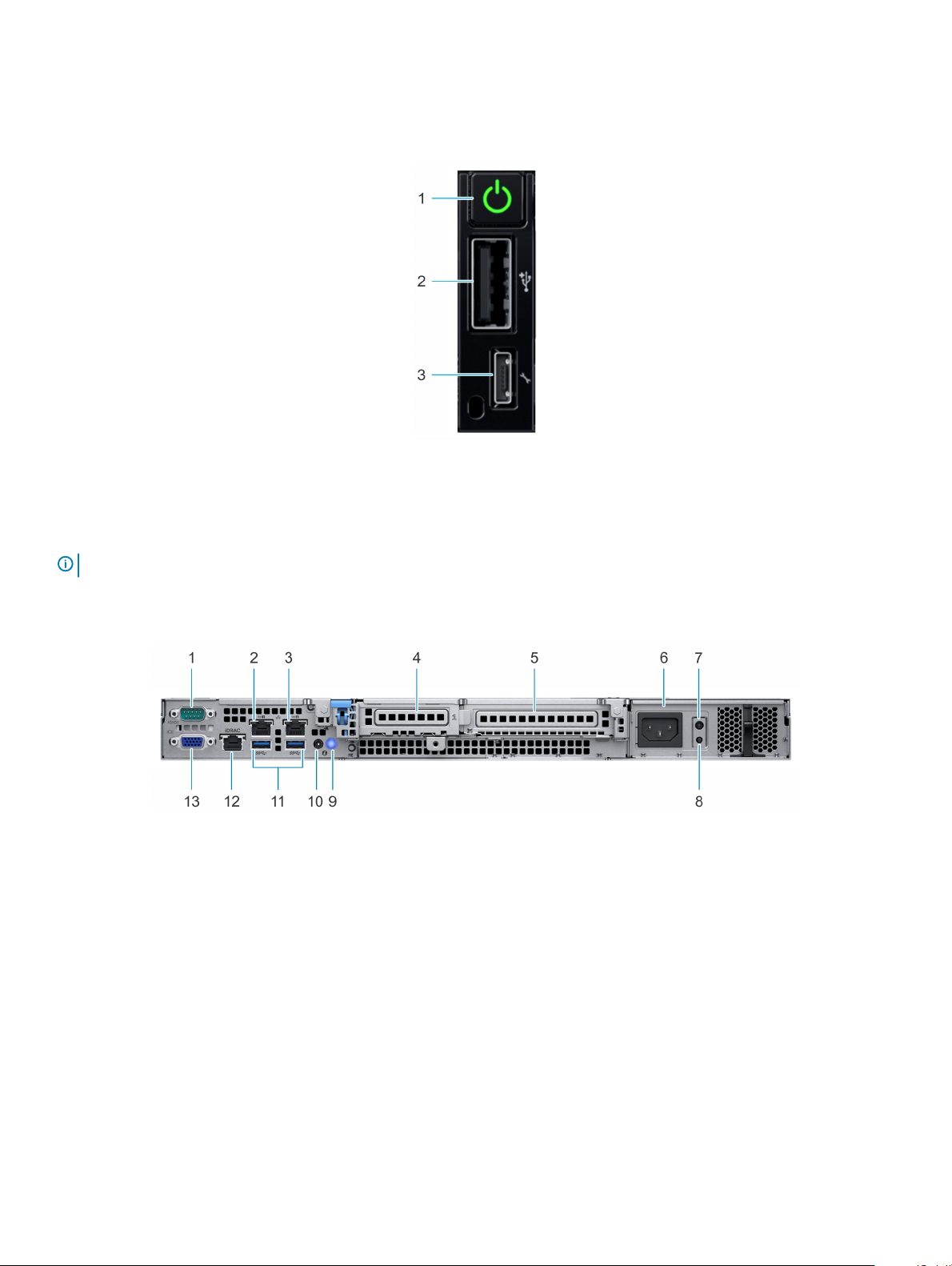
Right control panel
Figure 4. Right control panel view
1 Power button 2 USB 2.0-compliant port
3 iDRAC direct Micro USB port
NOTE: For more information on the ports, see the Ports and connectors specications section.
Rear view of the system
Figure 5. Rear view of the system
1
Serial port 2 NIC port (Gb 1)
3 NIC port (Gb 2) 4 Half-height PCIe expansion card slot
5 Full-height PCIe expansion card slot 6 Power supply unit
7 PSU Built-in Self Test (BIST) LED 8 PSU Built-in Self Test (BIST) button
9 System identication button 10 System status indicator cable port (CMA)
11 USB 3.0 ports (2) 12 iDRAC dedicated NIC port
13 VGA port
For more information about the ports and connectors, see the Technical Specications section.
Dell EMC PowerEdge R240 system overview
10
Page 11
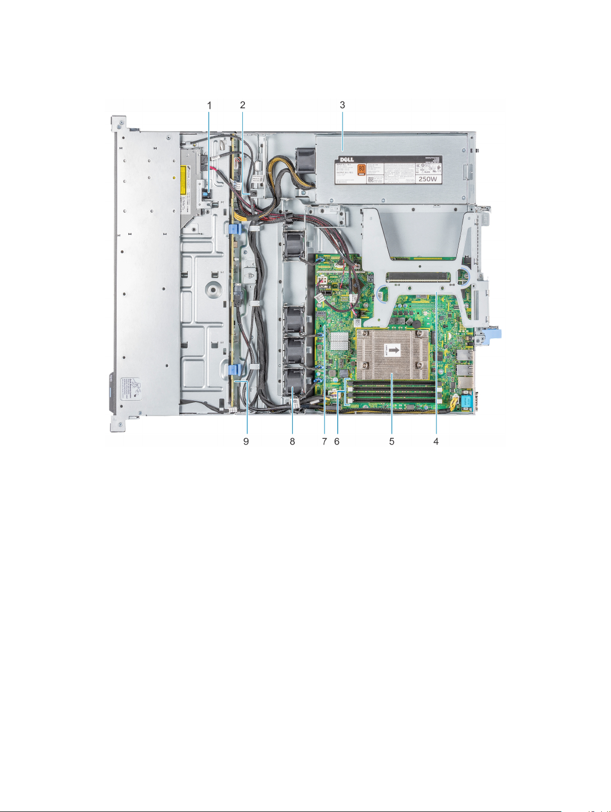
Inside the system
Figure 6. Inside the system - 4 x 3.5-inch drive system
1
Optical drive 2 Intrusion switch
3 Cabled AC power supply unit 4 Expansion card riser
5 Processor and heat sink 6 Memory module sockets
7 System board 8 Fan (4)
9 Drive backplane
Dell EMC PowerEdge R240 system overview 11
Page 12
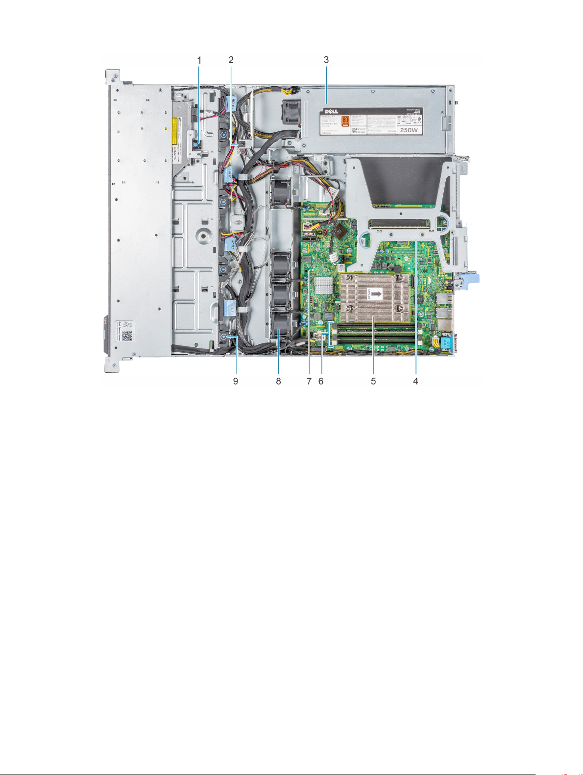
Figure 7. Inside the system - 4 x 3.5-inch cabled drive system
1
Optical drive 2 Intrusion switch
3 Cabled AC power supply unit 4 Expansion card riser
5 Processor and heat sink 6 Memory module sockets
7 System board 8 Fan (4)
9 Cabled drive
Locating the information tag of your system
Your system is identied by a unique Express Service Code and Service Tag number. You can view the Express Service Code and Service
Tag by pulling out the information tag located on the front of the system. Alternatively, the information may be on the Mini Enterprise
Service Tag (MEST) label on the chassis, on the rear of the system. This information is used by Dell to route support calls to the
appropriate personnel.
Dell EMC PowerEdge R240 system overview
12
Page 13
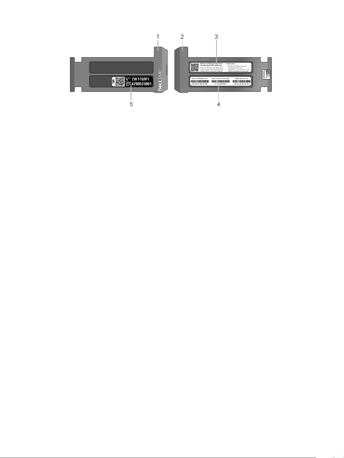
Figure 8. Locating Service Tag of your system
1 Information tag (front view) 2 Information tag (back view)
3 OpenManage Mobile (OMM) label 4 iDRAC MAC address and iDRAC secure password label
5 Service Tag, Express Service Code, QRL label
Dell EMC PowerEdge R240 system overview 13
Page 14

3
Initial system setup and conguration
Setting up your system
Perform the following steps to set up your system:
1 Unpack the system.
2 Install the system into the rack. For more information about installing the system into the rack, see the Rail Installation Guide at
Dell.com/poweredgemanuals.
3 Connect the peripherals to the system.
4 Connect the system to its electrical outlet.
5 Power on the system by pressing the power button or by using iDRAC.
6 Power on the attached peripherals.
For more information about setting up your system, see the Getting Started Guide that shipped with your system.
iDRAC conguration
The Integrated Dell Remote Access Controller (iDRAC) is designed to make system administrators more productive and improve the overall
availability of Dell systems. iDRAC alerts administrators about system issues and enables them to perform remote system management.
This reduces the need for physical access to the system.
Options to set up iDRAC IP address
To enable communication between your system and iDRAC, you must rst congure the network settings based on your network
infrastructure.
NOTE
: For static IP conguration, you must request for it at the time of purchase.
This option is set to DHCP by Default. You can set up the IP address by using one of the following interfaces:
Interfaces
iDRAC Settings
utility
Dell Deployment
Toolkit
Dell Lifecycle
Controller
NOTE: To access iDRAC, ensure that you connect the ethernet cable to the iDRAC9 dedicated network port. You can also access
iDRAC through the shared LOM mode, if you have opted for a system that has the shared LOM mode enabled.
Document/Section
Dell Integrated Dell Remote Access Controller User's Guide at Dell.com/poweredgemanuals
Dell Deployment Toolkit User’s Guide at Dell.com/openmanagemanuals > OpenManage Deployment Toolkit
Dell Lifecycle Controller User’s Guide at Dell.com/poweredgemanuals
14 Initial system setup and conguration
Page 15

Log in to iDRAC
You can log in to iDRAC as:
• iDRAC user
• Microsoft Active Directory user
• Lightweight Directory Access Protocol (LDAP) user
If you have opted for secure default access to iDRAC, you must use the iDRAC secure default password available on the system
Information tag. If you have not opted for secure default access to iDRAC, then use the default user name and password –root and
calvin. You can also log in by using your Single Sign-On or Smart Card.
NOTE: You must have the iDRAC credentials to log in to iDRAC.
NOTE: Ensure that you change the default user name and password after setting up the iDRAC IP address.
NOTE: The Intel Quick Assist Technology (QAT) on the Dell EMC PowerEdge R240 is supported with chipset integration and is
enabled through an optional license. The license les are enabled on the sleds through iDRAC.
For more information about drivers, documentation, and white papers on the Intel QAT, see https://01.org/intel-quickassist-technology.
For more information about logging in to the iDRAC and iDRAC licenses, see the latest Integrated Dell Remote Access Controller User's
Guide at Dell.com/poweredgemanuals.
You can also access iDRAC by using RACADM. For more information, see the RACADM Command Line Interface Reference Guide at
Dell.com/poweredgemanuals.
Options to install the operating system
If the system is shipped without an operating system, install a supported operating system by using one of the following resources:
Table 1. Resources to install the operating system
Resources Location
iDRAC Dell.com/idracmanuals
Lifecycle Controller Dell.com/idracmanuals > Lifecycle Controller
OpenManage Deployment Toolkit Dell.com/openmanagemanuals > OpenManage Deployment Toolkit
Dell certied VMware ESXi Dell.com/virtualizationsolutions
Installation and How-to videos for supported operating systems on
PowerEdge systems
Methods to download rmware and drivers
You can download the rmware and drivers by using any of the following methods:
Supported Operating Systems for Dell EMC PowerEdge systems
Initial system setup and
conguration 15
Page 16

Table 2. Firmware and drivers
Methods Location
From the Dell EMC support site Dell.com/support/home
Using Dell Remote Access Controller Lifecycle Controller (iDRAC
with LC)
Using Dell Repository Manager (DRM) Dell.com/openmanagemanuals > Repository Manager
Using Dell OpenManage Essentials (OME) Dell.com/openmanagemanuals > OpenManage Essentials
Using Dell Server Update Utility (SUU) Dell.com/openmanagemanuals > Server Update Utility
Using Dell OpenManage Deployment Toolkit (DTK) Dell.com/openmanagemanuals > OpenManage Deployment Toolkit
Using iDRAC virtual media Dell.com/idracmanuals
Dell.com/idracmanuals
Downloading drivers and rmware
Dell EMC recommends that you download and install the latest BIOS, drivers, and systems management rmware on your system.
Prerequisite
Ensure that you clear the web browser cache before downloading the drivers and rmware.
Steps
1 Go to Dell.com/support/home.
2 In the Drivers & Downloads section, type the Service Tag of your system in the Enter a Service Tag or product ID box, and then click
Submit.
NOTE
: If you do not have the Service Tag, select Detect Product to allow the system to automatically detect the Service
Tag, or click View products, and navigate to your product.
3 Click Drivers & Downloads.
The drivers that are applicable to your system are displayed.
4 Download the drivers to a USB drive, CD, or DVD.
16
Initial system setup and conguration
Page 17

Pre-operating system management applications
You can manage basic settings and features of a system without booting to the operating system by using the system rmware.
Topics:
• Options to manage the pre-operating system applications
• System Setup
• Dell Lifecycle Controller
• Boot Manager
• PXE boot
Options to manage the pre-operating system applications
Your system has the following options to manage the pre-operating system applications:
• System Setup
• Dell Lifecycle Controller
• Boot Manager
• Preboot Execution Environment (PXE)
4
System Setup
By using the System Setup screen, you can congure the BIOS settings, iDRAC settings, and device settings of your system.
: Help text for the selected eld is displayed in the graphical browser by default. To view the help text in the text browser,
NOTE
press F1.
You can access system setup by one of the following:
• Standard graphical browser—The browser is enabled by default.
• Text browser—The browser is enabled by using Console Redirection.
Viewing System Setup
To view the System Setup screen, perform the following steps:
1 Power on, or restart your system.
2 Press F2 immediately after you see the following message:
F2 = System Setup
: If your operating system begins to load before you press F2, wait for the system to nish booting, and then restart
NOTE
your system and try again.
Pre-operating system management applications 17
Page 18

System Setup details
The System Setup Main Menu screen details are explained as follows:
Option Description
System BIOS Enables you to congure BIOS settings.
iDRAC Settings Enables you to congure the iDRAC settings.
The iDRAC settings utility is an interface to set up and congure the iDRAC parameters by using UEFI (Unied
Extensible Firmware Interface). You can enable or disable various iDRAC parameters by using the iDRAC settings
utility. For more information about this utility, see Integrated Dell Remote Access Controller User’s Guide at
Dell.com/poweredgemanuals.
Device Settings Enables you to congure device settings.
System BIOS
You can use the System BIOS screen to edit specic functions such as boot order, system password, setup password, set the SATA mode,
and enable or disable USB ports.
Viewing System BIOS
To view the System BIOS screen, perform the following steps:
1 Power on, or restart your system.
2 Press F2 immediately after you see the following message:
F2 = System Setup
NOTE
: If the operating system begins to load before you press F2, wait for the system to nish booting, and then restart
the system and try again.
3 On the System Setup Main Menu screen, click System BIOS.
System BIOS Settings details
The System BIOS Settings screen details are explained as follows:
Option
System Information Species information about the system such as the system model name, BIOS version, and Service Tag.
Memory Settings Species information and options related to the installed memory.
Processor Settings Species information and options related to the processor such as speed and cache size.
SATA Settings Species options to enable or disable the integrated SATA controller and ports.
Boot Settings
Description
Species options to specify the Boot mode (BIOS or UEFI). Enables you to modify UEFI and BIOS boot settings.
Network Settings Species options to manage the UEFI network settings and boot protocols.
18 Pre-operating system management applications
Page 19

Option Description
Legacy network settings are managed from the Device Settings menu.
Integrated Devices Species options to manage integrated device controllers and ports, species related features and options.
Serial
Communication
System Prole
Settings
System Security Species options to congure the system security settings, such as system password, setup password, Trusted
Redundant OS
Control
Miscellaneous
Settings
Species options to manage the serial ports, its related features and options.
Species options to change the processor power management settings, memory frequency.
Platform Module (TPM) security, and UEFI secure boot. It also manages the power button on the system.
Sets the redundant OS info for redundant OS control.
Species options to change the system date and time.
System Information
You can use the System Information screen to view system properties such as Service Tag, system model name, and BIOS version.
Viewing System Information
To view the System Information screen, perform the following steps:
1 Power on, or restart your system.
2 Press F2 immediately after you see the following message:
F2 = System Setup
NOTE
: If your operating system begins to load before you press F2, wait for the system to nish booting, and then restart
your system and try again.
3 On the System Setup Main Menu screen, click System BIOS.
4 On the System BIOS screen, click System Information.
System Information details
The System Information screen details are explained as follows:
Option
System Model
Name
System BIOS
Version
System
Management
Engine Version
System Service Tag Species the system Service Tag.
System
Manufacturer
Description
Species the system model name.
Species the BIOS version installed on the system.
Species the current version of the Management Engine rmware.
Species the name of the system manufacturer.
Pre-operating system management applications 19
Page 20

Option Description
System
Manufacturer
Contact
Information
System CPLD
Version
UEFI Compliance
Version
Species the contact information of the system manufacturer.
Species the current version of the system complex programmable logic device (CPLD) rmware.
Species the UEFI compliance level of the system rmware.
Memory Settings
You can use the Memory Settings screen to view all the memory settings and enable or disable specic memory functions, such as system
memory testing and node interleaving.
Viewing Memory Settings
To view the Memory Settings screen, perform the following steps:
1 Power on, or restart your system.
2 Press F2 immediately after you see the following message:
F2 = System Setup
NOTE
: If the operating system begins to load before you press F2, wait for the system to nish booting, and then restart
the system and try again.
3 On the System Setup Main Menu screen, click System BIOS.
4 On the System BIOS screen, click Memory Settings.
Memory Settings details
The Memory Settings screen details are explained as follows:
Option
System Memory
Size
System Memory
Type
System Memory
Speed
System Memory
Voltage
Video Memory Species the amount of video memory.
System Memory
Testing
Memory Operating
Mode
Description
Species the memory size in the system.
Species the type of memory installed in the system.
Species the system memory speed.
Species the system memory voltage.
Species whether the system memory tests are run during system boot. Options are Enabled and Disabled. This
option is set to Disabled by default.
Species the memory operating mode. This option is set to Optimizer Mode by default.
NOTE: The Memory Operating Mode option can have dierent default and available options based on the
memory conguration of your system.
20 Pre-operating system management applications
Page 21

Option Description
Current State of
Memory Operating
Mode
Species the current state of the memory operating mode.
Processor Settings
You can use the Processor Settings screen to view the processor settings, and perform specic functions such as enabling virtualization
technology, hardware prefetcher, and logical processor idling.
Viewing Processor Settings
To view the Processor Settings screen, perform the following steps:
1 Power on, or restart your system.
2 Press F2 immediately after you see the following message:
F2 = System Setup
NOTE: If your operating system begins to load before you press F2, wait for the system to nish booting, and then restart
your system and try again.
3 On the System Setup Main Menu screen, click System BIOS.
4 On the System BIOS screen, click Processor Settings.
Processor Settings details
The Processor Settings screen details are explained as follows:
Option
Logical Processor
Virtualization
Technology
Adjacent Cache
Line Prefetch
Hardware
Prefetcher
Logical Processor
Idling
x2APIC Mode Enables or disables the x2APIC mode. This option is set to Disabled by default.
Number of Cores
per Processor
Processor Core
Speed
Description
Enables or disables the logical processors and displays the number of logical processors. If this option is set to
Enabled, the BIOS displays all the logical processors. If this option is set to Disabled, the BIOS displays only one
logical processor per core. This option is set to Enabled by default.
Enables or disables the virtualization technology for the processor. This option is set to Enabled by default.
Optimizes the system for applications that need high utilization of sequential memory access. This option is set to
Enabled by default. You can disable this option for applications that need high utilization of random memory
access.
Enables or disables the hardware prefetcher. This option is set to Enabled by default.
Enables you to improve the energy eciency of a system. It uses the operating system core parking algorithm and
parks some of the logical processors in the system which in turn allows the corresponding processor cores to
transition into a lower power idle state. This option can only be enabled if the operating system supports it. It is set
to Disabled by default.
Controls the number of enabled cores in each processor. This option is set to All by default.
Species the maximum core frequency of the processor.
Pre-operating system management applications 21
Page 22

Option Description
Processor 1
The following settings are displayed for each processor installed in the system:
Option Description
Family-ModelStepping
Brand Species the brand name.
Level 2 Cache Species the total L2 cache.
Level 3 Cache Species the total L3 cache.
Number of Cores Species the number of cores per processor.
Microcode Indicates the Microcode update signature.
Species the family, model, and stepping of the processor as dened by Intel.
SATA Settings
You can use the SATA Settings screen to view the SATA settings of SATA devices and enable SATA on your system.
Viewing SATA Settings
To view the SATA Settings screen, perform the following steps:
1 Power on, or restart your system.
2 Press F2 immediately after you see the following message:
F2 = System Setup
NOTE
: If your operating system begins to load before you press F2, wait for the system to nish booting, and then restart
your system and try again.
3 On the System Setup Main Menu screen, click System BIOS.
4 On the System BIOS screen, click SATA Settings.
SATA Settings details
The SATA Settings screen details are explained as follows:
Option
Embedded SATA Enables the embedded SATA option to be set to O, AHCI, or RAID modes. This option is set to AHCI Mode by
Security Freeze
Lock
Write Cache Enables or disables the command for the embedded SATA drives during POST. This option is set to Disabled by
Port A Sets the drive type of the selected device.
Description
default.
Sends Security Freeze Lock command to the embedded SATA drives during POST. This option is applicable only
for AHCI Mode. This option is set to Enabled by default.
default.
When the Embedded SATA setting is AHCI Mode, BIOS support is always enabled.
Option Description
Model Species the drive model of the selected device.
22 Pre-operating system management applications
Page 23

Option Description
Option Description
Drive Type Species the type of drive attached to the SATA port.
Capacity Species the total capacity of the hard drive. This eld is undened for removable media
devices such as optical drives.
Port B Sets the drive type of the selected device.
When the Embedded SATA setting is AHCI Mode, BIOS support is always enabled.
Option Description
Model Species the drive model of the selected device.
Drive Type Species the type of drive attached to the SATA port.
Capacity Species the total capacity of the hard drive. This eld is undened for removable media
devices such as optical drives.
Port C Sets the drive type of the selected device.
When the Embedded SATA setting is AHCI Mode, BIOS support is always enabled.
Option Description
Model Species the drive model of the selected device.
Drive Type Species the type of drive attached to the SATA port.
Capacity Species the total capacity of the hard drive. This eld is undened for removable media
devices such as optical drives.
Port D Sets the drive type of the selected device.
When the Embedded SATA setting is AHCI Mode, BIOS support is always enabled.
Option Description
Model Species the drive model of the selected device.
Drive Type Species the type of drive attached to the SATA port.
Capacity Species the total capacity of the hard drive. This eld is undened for removable media
devices such as optical drives.
Port E Sets the drive type of the selected device.
When the Embedded SATA setting is AHCI Mode, BIOS support is always enabled.
Option Description
Model Species the drive model of the selected device.
Drive Type Species the type of drive attached to the SATA port.
Capacity Species the total capacity of the hard drive. This eld is undened for removable media
devices such as optical drives.
Port F Sets the drive type of the selected device.
When the Embedded SATA setting is AHCI Mode, BIOS support is always enabled.
Pre-operating system management applications 23
Page 24

Option Description
Option Description
Model Species the drive model of the selected device.
Drive Type Species the type of drive attached to the SATA port.
Capacity Species the total capacity of the hard drive. This eld is undened for removable media
devices such as optical drives.
Boot Settings
You can use the Boot Settings screen to set the boot mode to either BIOS or UEFI. It also enables you to specify the boot order.
• UEFI: The Unied Extensible Firmware Interface (UEFI) is a new interface between operating systems and platform rmware. The
interface consists of data tables with platform related information, boot and runtime service calls that are available to the operating
system and its loader. The following benets are available when the Boot Mode is set to UEFI:
– Support for drive partitions larger than 2 TB.
– Enhanced security (e.g., UEFI Secure Boot).
– Faster boot time.
• BIOS: The BIOS Boot Mode is the legacy boot mode. It is maintained for backward compatibility.
Viewing Boot Settings
To view the Boot Settings screen, perform the following steps:
1 Power on, or restart your system.
2 Press F2 immediately after you see the following message:
F2 = System Setup
NOTE
: If your operating system begins to load before you press F2, wait for the system to nish booting, and then restart
your system and try again.
3 On the System Setup Main Menu screen, click System BIOS.
4 On the System BIOS screen, click Boot Settings.
Boot Settings details
The Boot Settings screen details are explained as follows:
Option
Boot Mode Enables you to set the boot mode of the system.
Description
CAUTION: Switching the boot mode may prevent the system from booting if the operating system is not
installed in the same boot mode.
If the operating system supports UEFI, you can set this option to UEFI. Setting this eld to BIOS allows
compatibility with non-UEFI operating systems.
NOTE: Setting this eld to UEFI disables the BIOS Boot Settings menu.
This option is set to UEFI by default.
Boot Sequence
Retry
24 Pre-operating system management applications
Enables or disables the Boot Sequence Retry feature. If this option is set to Enabled and the system fails to boot,
the system re-attempts the boot sequence after 30 seconds. This option is set to Enabled by default.
Page 25

Option Description
Hard-Disk Failover Species the drive that is booted in the event of a drive failure. The devices are selected in the Hard-Disk Drive
Sequence on the Boot Option Setting menu. When this option is set to Disabled, only the rst drive in the list is
attempted to boot. When this option is set to Enabled, all drives are attempted to boot in the order selected in the
Hard-Disk Drive Sequence. This option is not enabled for UEFI Boot Mode. This option is set to Disabled by
default.
Generic USB boot Enables or disables generic USB boot.
Hard-disk Drive
Placeholder
UEFI Boot Settings Enables or disables UEFI Boot options.
Enables or disables Hard-disk Drive Placeholder.
The Boot options include IPv4 PXE and IPv6 PXE. This option is set to IPv4 by default.
NOTE: This option is enabled only if the boot mode is UEFI.
Network Settings
You can use the Network Settings screen to modify UEFI PXE, iSCSI, and HTTP boot settings. The network settings option is available
only in the UEFI mode.
NOTE: BIOS does not control network settings in the BIOS mode. For the BIOS boot mode, the optional Boot ROM of the
network controllers handles the network settings.
Viewing Network Settings
To view the Network Settings screen, perform the following steps:
1 Power on, or restart your system.
2 Press F2 immediately after you see the following message:
F2 = System Setup
NOTE
: If your operating system begins to load before you press F2, wait for the system to nish booting, and then restart
your system and try again.
3 On the System Setup Main Menu screen, click System BIOS.
4 On the System BIOS screen, click Network Settings.
Network Settings screen details
The Network Settings screen details are explained as follows:
Option
PXE Device n (n = 1
to 4)
PXE Device n
Settings(n = 1 to 4)
HTTP Device n (n =
1 to 4)
HTTP Device n
Settings (n = 1 to 4)
Description
Enables or disables the device. When enabled, a UEFI PXE boot option is created for the device.
Enables you to control the conguration of the PXE device.
Enables or disables the device. When enabled, a UEFI HTTP boot option is created for the device.
Enables you to control the conguration of the HTTP device.
Pre-operating system management applications 25
Page 26

UEFI iSCSI Settings
You can use the iSCSI Settings screen to modify iSCSI device settings. The iSCSI Settings option is available only in the UEFI boot mode.
BIOS does not control network settings in the BIOS boot mode. For the BIOS boot mode, the option ROM of the network controller
handles the network settings.
Viewing UEFI iSCSI Settings
To view the UEFI iSCSI Settings screen, perform the following steps:
1 Power on, or restart your system.
2 Press F2 immediately after you see the following message:
F2 = System Setup
NOTE: If your operating system begins to load before you press F2, wait for the system to nish booting, and then restart
your system and try again.
3 On the System Setup Main Menu screen, click System BIOS.
4 On the System BIOS screen, click Network Settings.
5 On the Network Settings screen, scroll down to view UEFI iSCSI Settings.
UEFI iSCSI Settings details
The UEFI iSCSI Settings screen details are explained as follows:
Option
iSCSI Initiator
Name
iSCSI Device1 Enables or disables the iSCSI device. When enabled, a UEFI boot option is created for the iSCSI device
iSCSI Device1
Settings
Description
Species the name of the iSCSI initiator (iqn format).
automatically.
Enables you to control the conguration of the iSCSI device.
Integrated Devices
You can use the Integrated Devices screen to view and congure the settings of all integrated devices including the video controller,
integrated RAID controller, and the USB ports.
Viewing Integrated Devices
To view the Integrated Devices screen, perform the following steps:
1 Power on, or restart your system.
2 Press F2 immediately after you see the following message:
F2 = System Setup
: If your operating system begins to load before you press F2, wait for the system to nish booting, and then restart
NOTE
your system and try again.
3 On the System Setup Main Menu screen, click System BIOS.
Pre-operating system management applications
26
Page 27

4 On the System BIOS screen, click Integrated Devices.
Integrated Devices details
The Integrated Devices screen details are explained as follows:
Option Description
User Accessible
USB Ports
Internal USB Port Enables or disables the internal USB port. This option is set to On or O. This option is set to On by default.
iDRAC Direct USB
Port
Embedded NIC1
and NIC2
I/OAT DMA Engine Enables or disables the I/O Acceleration Technology (I/OAT) option. I/OAT is a set of DMA features designed to
Embedded Video
Controller
Congures the user accessible USB ports. Selecting Only Back Ports On disables the front USB ports; selecting
All Ports O disables all front and back USB ports;
The USB keyboard and mouse still function in certain USB ports during the boot process, depending on the
selection. After the boot process is complete, the USB ports will be enabled or disabled as per the setting.
NOTE: Selecting Only Back Ports On and All Ports O disables the USB management port and also
restricts access to the iDRAC features.
The iDRAC Direct USB port is managed by iDRAC exclusively with no host visibility. This option is set to ON or
OFF. When set to OFF, iDRAC does not detect any USB devices installed in this managed port. This option is set
to On by default.
NOTE: The Embedded NIC1 and NIC2 options are only available on systems that do not have Integrated
Network Card 1.
Enables or disables the Embedded NIC1 and NIC2 options. If set to Disabled, the NIC may still be available for
shared network access by the embedded management controller. The embedded NIC1 and NIC2 options are only
available on systems that do not have Network Daughter Cards (NDCs). The Embedded NIC1 and NIC2 option is
mutually exclusive with the Integrated Network Card 1 option. Congure the Embedded NIC1 and NIC2 option by
using the NIC management utilities of the system.
accelerate network trac and lower CPU utilization. Enable only if the hardware and software support the feature.
Enables or disables the use of Embedded Video Controller as the primary display. When set to Enabled, the
Embedded Video Controller will be the primary display even if add-in graphic cards are installed. When set to
Disabled, an add-in graphics card will be used as the primary display. BIOS will output displays to both the primary
add-in video and the embedded video during POST and pre-boot environment. The embedded video will then be
disabled right before the operating system boots. This option is set to
NOTE: When there are multiple add-in graphic cards installed in the system, the rst card discovered
during PCI enumeration is selected as the primary video. You might have to re-arrange the cards in the
slots in order to control which card is the primary video.
Enabled by default.
Current State of
Embedded Video
Controller
OS Watchdog
Timer
Memory Mapped
I/O above 4 GB
Slot Disablement Enables or disables the available PCIe slots on your system. The slot disablement feature controls the conguration
Displays the current state of the embedded video controller. The Current State of Embedded Video Controller
option is a read-only eld. If the Embedded Video Controller is the only display capability in the system (that is, no
add-in graphics card is installed), then the Embedded Video Controller is automatically used as the primary display
even if the Embedded Video Controller setting is set to Enabled.
If your system stops responding, this watchdog timer aids in the recovery of your operating system. When this
option is set to Enabled, the operating system initializes the timer. When this option is set to Disabled (the
default), the timer does not have any eect on the system.
Enables or disables the support for the PCIe devices that need large amounts of memory. Enable this option only
for 64-bit operating systems. This option is set to Enabled by default.
of the PCIe cards installed in the specied slot. Slots must be disabled only when the installed peripheral card
prevents booting into the operating system or causes delays in system startup. If the slot is disabled, both the
Option ROM and UEFI drivers are disabled. Only slots that are present on the system will be available for control.
Pre-operating system management applications 27
Page 28

Option Description
Table 3. Slot Disablement
Option Description
Slot 1
Enables or disables or only the boot driver is disabled
for the PCIe slot 1. This option is set to Enabled by
default.
Slot 2
Enables or disables or only the boot driver is disabled
for the PCIe slot 2. This option is set to Enabled by
default.
Serial Communication
You can use the Serial Communication screen to view the properties of the serial communication port.
Viewing Serial Communication
To view the Serial Communication screen, perform the following steps:
1 Power on, or restart your system.
2 Press F2 immediately after you see the following message:
F2 = System Setup
NOTE
: If your operating system begins to load before you press F2, wait for the system to nish booting, and then restart
your system and try again.
3 On the System Setup Main Menu screen, click System BIOS.
4 On the System BIOS screen, click Serial Communication.
Serial Communication details
The Serial Communication screen details are explained as follows:
Option
Serial
Communication
Serial Port Address Enables you to set the port address for serial devices. This eld sets the serial port address to either COM1 or
External Serial
Connector
28 Pre-operating system management applications
Description
Selects serial communication devices (Serial Device 1 and Serial Device 2) in BIOS. BIOS console redirection can
also be enabled, and the port address can be specied. This option is set to Auto by default.
COM2 (COM1=0x3F8, COM2=0x2F8). This option is set to Serial Device1=COM2 or Serial Device 2=COM1 by
default.
NOTE: You can use only Serial Device 2 for the Serial Over LAN (SOL) feature. To use console
redirection by SOL, congure the same port address for console redirection and the serial device.
NOTE: Every time the system boots, the BIOS syncs the serial MUX setting saved in iDRAC. The serial
MUX setting can independently be changed in iDRAC. Loading the BIOS default settings from within the
BIOS setup utility may not always revert the serial MUX setting to the default setting of Serial Device 1.
Enables you to associate the External Serial Connector to Serial Device 1, Serial Device 2, or the Remote Access
Device by using this option. This option is set to Serial Device 1 by default.
Page 29

Option Description
NOTE: Only Serial Device 2 can be used for Serial Over LAN (SOL). To use console redirection by SOL,
congure the same port address for console redirection and the serial device.
NOTE: Every time the system boots, the BIOS syncs the serial MUX setting saved in iDRAC. The serial
MUX setting can independently be changed in iDRAC. Loading the BIOS default settings from within the
BIOS setup utility may not always revert this setting to the default setting of Serial Device 1.
Failsafe Baud Rate Species the failsafe baud rate for console redirection. The BIOS attempts to determine the baud rate
automatically. This failsafe baud rate is used only if the attempt fails, and the value must not be changed. This
option is set to 115200 by default.
Remote Terminal
Type
Redirection After
Boot
Sets the remote console terminal type. This option is set to ANSIVT100/VT220 by default.
Enables or disables the BIOS console redirection when the operating system is loaded. This option is set to
Enabled by default.
System Prole Settings
You can use the System Prole Settings screen to enable specic system performance settings such as power management.
Viewing System Prole Settings
To view the System Prole Settings screen, perform the following steps:
1 Power on, or restart your system.
2 Press F2 immediately after you see the following message:
F2 = System Setup
NOTE
: If your operating system begins to load before you press F2, wait for the system to nish booting, and then restart
your system and try again.
3 On the System Setup Main Menu screen, click System BIOS.
4 On the System BIOS screen, click System Prole Settings.
System Prole Settings details
The System Prole Settings screen details are explained as follows:
Option
System Prole Sets the system prole. If you set the System Prole option to a mode other than Custom, the BIOS automatically
CPU Power
Management
Memory Frequency Sets the speed of the system memory. You can select Maximum Performance, Maximum Reliability, or a specic
Turbo Boost Enables or disables the processor to operate in the turbo boost mode. This option is set to Enabled by default.
C1E Enables or disables the processor to switch to a minimum performance state when it is idle. This option is set to
Description
sets the rest of the options. You can only change the rest of the options if the mode is set to Custom. This option
is set to Performance Per Watt (OS) by default.
NOTE: All the parameters on the system prole setting screen are available only when the System Prole
option is set to Custom.
Sets the CPU power management. This option is set to OS DBPM by default.
speed. This option is set to Maximum Performance by default.
Enabled by default.
Pre-operating system management applications 29
Page 30

Option Description
C States Enables or disables the processor to operate in all available power states. This option is set to Enabled by default.
Memory Refresh
Rate
Uncore Frequency Enables you to select the Processor Uncore Frequency option.
Sets the memory refresh rate to either 1x or 2x. This option is set to 1x by default.
Dynamic mode enables the processor to optimize power resources across the cores and uncore during runtime.
The optimization of the uncore frequency to either save power or optimize performance is inuenced by the
setting of the Energy Eciency Policy option.
Number of Turbo
Boost Enabled
Cores for Processor
1
Monitor/Mwait Enables the Monitor/Mwait instructions in the processor. This option is set to Enabled for all system proles,
PCI ASPM L1 Link
Power
Management
NOTE: If there are two processors installed in the system, you will see an entry for Number of Turbo
Boost Enabled Cores for Processor 2.
Controls the number of turbo boost enabled cores for Processor 1. The maximum number of cores is enabled by
default.
except Custom by default.
NOTE: This option can be disabled only if the C States option in the Custom mode is set to disabled.
NOTE: When C States is set to Enabled in the Custom mode, changing the Monitor/Mwait setting does
not impact the system power or performance.
Enables or disables the PCI ASPM L1 Link Power Management. This option is set to Enabled by default.
System Security
You can use the System Security screen to perform specic functions such as setting the system password, setup password and disabling
the power button.
Viewing System Security
To view the System Security screen, perform the following steps:
1 Power on, or restart your system.
2 Press F2 immediately after you see the following message:
F2 = System Setup
NOTE
: If your operating system begins to load before you press F2, wait for the system to nish booting, and then restart
your system and try again.
3 On the System Setup Main Menu screen, click System BIOS.
4 On the System BIOS screen, click System Security.
System Security Settings details
The System Security Settings screen details are explained as follows:
Option
CPU AES-NI Improves the speed of applications by performing encryption and decryption by using the Advanced Encryption
30 Pre-operating system management applications
Description
Standard Instruction Set (AES-NI). This option is set to Enabled by default.
Page 31

Option Description
System Password Sets the system password. This option is set to Enabled by default and is read-only if the password jumper is not
installed in the system.
Setup Password Sets the setup password. This option is read-only if the password jumper is not installed in the system.
Password Status Locks the system password. This option is set to Unlocked by default.
TPM Security
TPM Information Changes the operational state of the TPM. This option is set to No Change by default.
TPM Status Species the TPM status.
TPM Command Controls the Trusted Platform Module (TPM). When set to None, no command is sent to the TPM. When set to
Intel(R) TXT Enables or disables the Intel Trusted Execution Technology (TXT) option. To enable the Intel TXT option,
NOTE: The TPM menu is available only when the TPM module is installed.
Enables you to control the reporting mode of the TPM. The TPM Security option is set to O by default. You can
only modify the TPM Status TPM Activation, and the Intel SGX elds if the TPM Status eld is set to either On
with Pre-boot Measurements or On without Pre-boot Measurements.
Activate, the TPM is enabled and activated. When set to Deactivate, the TPM is disabled and deactivated. When
set to Clear, all the contents of the TPM are cleared. This option is set to None by default.
CAUTION: Clearing the TPM results in the loss of all keys in the TPM. The loss of TPM keys may aect
booting to the operating system.
This eld is read-only when TPM Security is set to O. The action requires an additional reboot before it can take
eect.
virtualization technology and TPM Security must be enabled with Pre-boot measurements. This option is set to O
by default.
When TPM 2.0 is installed, TPM 2 Algorithm option is available. It enables you to select a hash algorithm from
those supported by the TPM (SHA1, SHA256). TPM 2 Algorithm option must be set to SHA256, to enable TXT.
Intel(R) SGX Enables or disables the Intel Software Guard Extension (SGX) option. This option is set to Software by default.
NOTE: The SGX menu is available, only when E-2186G/E-2176G/E-2174G CPU is installed
SGX Launch
Control Policy
Power Button Enables or disables the power button on the front of the system. This option is set to Enabled by default.
AC Power Recovery Sets how the system behaves after AC power is restored to the system. This option is set to Last by default.
AC Power Recovery
Delay
User Dened Delay
(60 s to 240 s)
UEFI Variable
Access
In-Band
Manageability
Interface
Secure Boot Enables Secure Boot, where the BIOS authenticates each pre-boot image by using the certicates in the Secure
Allows controlling the Launch Control Policy (LCP) of Software Guard Extensions (SGX) technology. This option is
set to Unlocked by default.
Sets the time delay for the system to power up after AC power is restored to the system. This option is set to
Immediate by default.
Sets the User Dened Delay option when the User Dened option for AC Power Recovery Delay is selected.
Provides varying degrees of securing UEFI variables. When set to Standard (the default), UEFI variables are
accessible in the operating system per the UEFI specication. When set to Controlled, selected UEFI variables are
protected in the environment and new UEFI boot entries are forced to be at the end of the current boot order.
When set to Disabled, this setting will hide the Management Engine's (ME), HECI devices, and the system's IPMI
devices from the operating system. This prevents the operating system from changing the ME power capping
settings, and blocks access to all in-band management tools. All management should be managed through out-ofband. This option is set to Enabled by default.
NOTE: BIOS update requires HECI devices to be operational and DUP updates require IPMI interface to
be operational. This setting needs to be set to Enabled to avoid updating errors.
Boot Policy. Secure Boot is set to Disabled by default.
Pre-operating system management applications 31
Page 32

Option Description
Secure Boot Policy When Secure Boot policy is set to Standard, the BIOS uses the system manufacturer’s key and certicates to
authenticate pre-boot images. When Secure Boot policy is set to Custom, the BIOS uses the user-dened key and
certicates. Secure Boot policy is set to Standard by default.
Secure Boot Mode Congures how the BIOS uses the Secure Boot Policy Objects (PK, KEK, db, dbx).
If the current mode is set to Deployed Mode, the available options are User Mode and Deployed Mode. If the
current mode is set to User Mode, the available options are User Mode, Audit Mode, and Deployed Mode.
Options Description
Secure Boot Policy
Summary
Secure Boot
Custom Policy
Settings
User Mode
Audit Mode
Deployed Mode
Species the list of certicates and hashes that secure boot uses to authenticate images.
Congures the Secure Boot Custom Policy. To enable this option, set the Secure Boot Policy to Custom option.
In User Mode, PK must be installed, and BIOS performs signature verication on
programmatic attempts to update policy objects.
The BIOS allows unauthenticated programmatic transitions between modes.
In Audit mode, PK is not present. The BIOS does not authenticate programmatic updates
to the policy objects, and transitions between modes.
Audit Mode is useful for programmatically determining a working set of policy objects.
BIOS performs signature verication on pre-boot images and logs results in the image
Execution Information Table, but executes the images whether they pass or fail
verication.
Deployed Mode is the most secure mode. In Deployed Mode, PK must be installed and
the BIOS performs signature verication on programmatic attempts to update policy
objects.
Deployed Mode restricts the programmatic mode transitions.
Creating a system and setup password
Prerequisite
Ensure that the password jumper is enabled. The password jumper enables or disables the system password and setup password features.
For more information, see the System board jumper settings section.
NOTE
: If the password jumper setting is disabled, the existing system password and setup password are deleted and you need
not provide the system password to boot the system.
Steps
1 To enter System Setup, press F2 immediately after turning on or rebooting your system.
2 On the System Setup Main Menu screen, click System BIOS > System Security.
3 On the System Security screen, verify that Password Status is set to Unlocked.
4 In the System Password eld, type your system password, and press Enter or Tab.
Pre-operating system management applications
32
Page 33

Use the following guidelines to assign the system password:
• A password can have up to 32 characters.
• The password can contain the numbers 0 through 9.
• Only the following special characters are allowed: space, (”), (+), (,), (-), (.), (/), (;), ([), (\), (]), (`).
A message prompts you to reenter the system password.
5 Reenter the system password, and click OK.
6 In the Setup Password eld, type your setup password and press Enter or Tab.
A message prompts you to reenter the setup password.
7 Reenter the setup password, and click OK.
8 Press Esc to return to the System BIOS screen. Press Esc again.
A message prompts you to save the changes.
NOTE: Password protection does not take eect until the system reboots.
Using your system password to secure the system
About this task
If you have assigned a setup password, the system accepts your setup password as an alternate system password.
Steps
1 Power on or reboot your system.
2 Type the system password and press Enter.
Next step
When Password Status is set to Locked, type the system password and press Enter when prompted at reboot.
: If an incorrect system password is typed, the system displays a message and prompts you to reenter your password. You
NOTE
have three attempts to type the correct password. After the third unsuccessful attempt, the system displays an error message
that the system has stopped functioning and must be turned o. Even after you turn o and restart the system, the error
message is displayed until the correct password is entered.
Deleting or changing system and setup password
Prerequisite
: You cannot delete or change an existing system or setup password if the Password Status is set to Locked.
NOTE
Steps
1 To enter System Setup, press F2 immediately after turning on or restarting your system.
2 On the System Setup Main Menu screen, click System BIOS > System Security.
3 On the System Security screen, ensure that Password Status is set to Unlocked.
4 In the System Password eld, change or delete the existing system password, and then press Enter or Tab.
5 In the Setup Password eld, alter or delete the existing setup password, and then press Enter or Tab.
: If you change the system password or setup password, a message prompts you to reenter the new password. If you
NOTE
delete the system password or setup password, a message prompts you to conrm the deletion.
6 Press Esc to return to the System BIOS screen. Press Esc again, and a message prompts you to save the changes.
7 Select Setup Password, change, or delete the existing setup password and press Enter or Tab.
: If you change the system password or setup password, a message prompts you to reenter the new password. If you
NOTE
delete the system password or setup password, a message prompts you to conrm the deletion.
Pre-operating system management applications 33
Page 34

Operating with setup password enabled
If Setup Password is set to Enabled, type the correct setup password before modifying the system setup options.
If you do not type the correct password in three attempts, the system displays the following message:
Invalid Password! Number of unsuccessful password attempts: <x> System Halted! Must power down.
Password Invalid. Number of unsuccessful password attempts: <x> Maximum number of password
attempts exceeded.System halted.
Even after you turn o and restart the system, the error message is displayed until the correct password is typed. The following options are
exceptions:
• If System Password is not set to Enabled and is not locked through the Password Status option, you can assign a system password.
For more information, see the System Security Settings screen section.
• You cannot disable or change an existing system password.
NOTE: You can use the password status option with the setup password option to protect the system password from
unauthorized changes.
Redundant OS Control
In the Redundant OS Control screen you can set the redundant OS information. This enables you to set up a physical recovery disk on the
system.
Viewing Redundant OS Control
To view the Redundant OS Control screen, perform the following steps:
1 Power on, or restart your system.
2 Press F2 immediately after you see the following message:
F2 = System Setup
NOTE
: If your operating system begins to load before you press F2, wait for the system to nish booting, and then restart
your system and try again.
3 On the System Setup Main Menu screen, click System BIOS.
4 On the System BIOS screen, click Redundant OS Control.
Redundant OS Control screen details
The Redundant OS Control screen details are explained as follows:
Option
Redundant OS
Location
Description
Enables you to select a backup disk from the following devices:
• None
• IDSDM
• SATA Ports in AHCI mode
• BOSS PCIe Cards (Internal M.2 Drives)
• Internal USB
34 Pre-operating system management applications
Page 35

Option Description
NOTE: RAID congurations and NVMe cards not are included as BIOS does not have the ability to
distinguish between individual drives in those congurations.
Redundant OS
State
Redundant OS Boot
NOTE: This option is disabled if Redundant OS Location is set to None.
When set to Visible, the backup disk is visible to the boot list and OS. When set to Hidden, the backup disk is
disabled and is not visible to the boot list and OS. This option is set to Visible by default.
NOTE: BIOS will disable the device in hardware, so it cannot be accessed by the OS.
NOTE: This option is disabled if Redundant OS Location is set to None or if Redundant OS State is set to
Hidden.
When set to Enabled, BIOS boots to the device specied in Redundant OS Location. When set to Disabled, BIOS
preserves the current boot list settings. This option is set to Enabled by default.
Miscellaneous Settings
You can use the Miscellaneous Settings screen to perform specic functions such as updating the asset tag and changing the system
date and time.
Viewing Miscellaneous Settings
To view the Miscellaneous Settings screen, perform the following steps:
1 Power on, or restart your system.
2 Press F2 immediately after you see the following message:
F2 = System Setup
NOTE
: If your operating system begins to load before you press F2, wait for the system to nish booting, and then restart
your system and try again.
3 On the System Setup Main Menu screen, click System BIOS.
4 On the System BIOS screen, click Miscellaneous Settings.
Miscellaneous Settings details
The Miscellaneous Settings screen details are explained as follows:
Option
System Time Enables you to set the time on the system.
System Date Enables you to set the date on the system.
Asset Tag Species the asset tag and enables you to modify it for security and tracking purposes.
Keyboard NumLock Enables you to set whether the system boots with the NumLock enabled or disabled. This option is set to On by
F1/F2 Prompt on
Error
Description
default.
NOTE: This option does not apply to 84-key keyboards.
Enables or disables the F1/F2 prompt on error. This option is set to Enabled by default. The F1/F2 prompt also
includes keyboard errors.
Pre-operating system management applications 35
Page 36

Option Description
Load Legacy Video
Option ROM
Dell Wyse P25/P45
BIOS Access
Power Cycle
Request
Enables you to determine whether the system BIOS loads the legacy video (INT 10H) option ROM from the video
controller. Selecting Enabled in the operating system does not support UEFI video output standards. This eld is
available only for UEFI boot mode. You cannot set the option to Enabled if UEFI Secure Boot mode is enabled.
This option is set to Disabled by default.
Enables or disables the Dell Wyse P25/P45 BIOS Access. This option is set to Enabled by default.
Enables or disables the Power Cycle Request. This option is set to None by default.
iDRAC Settings utility
The iDRAC settings utility is an interface to set up and congure the iDRAC parameters by using UEFI. You can enable or disable various
iDRAC parameters by using the iDRAC settings utility.
NOTE: Accessing some of the features on the iDRAC settings utility needs the iDRAC Enterprise License upgrade.
For more information about using iDRAC, see Dell Integrated Dell Remote Access Controller User's Guide at Dell.com/poweredgemanuals.
Device Settings
Device Settings enables you to congure the below device parameters:
• Controller Conguration Utility
• Embedded NIC Port1-X Conguration
• NICs in slotX, Port1-X Conguration
• BOSS Card conguration
Dell Lifecycle Controller
Dell Lifecycle Controller (LC) provides advanced embedded systems management capabilities including system deployment, conguration,
update, maintenance, and diagnosis. LC is delivered as part of the iDRAC out-of-band solution and Dell system embedded Unied
Extensible Firmware Interface (UEFI) applications.
Embedded system management
The Dell Lifecycle Controller provides advanced embedded system management throughout the lifecycle of the system. The Dell Lifecycle
Controller can be started during the boot sequence and can function independently of the operating system.
NOTE
: Certain platform congurations may not support the full set of features provided by the Dell Lifecycle Controller.
For more information about setting up the Dell Lifecycle Controller, conguring hardware and rmware, and deploying the operating system,
see the Dell Lifecycle Controller documentation at Dell.com/poweredgemanuals.
Pre-operating system management applications
36
Page 37

Boot Manager
The Boot Manager screen enables you to select boot options and diagnostic utilities.
Viewing Boot Manager
About this task
To enter Boot Manager:
Steps
1 Power on, or restart your system.
2 Press F11 when you see the following message:
F11 = Boot Manager
If your operating system begins to load before you press F11, allow the system to complete the booting, and then restart your system
and try again.
Boot Manager main menu
Menu item
Continue Normal
Boot
One-shot Boot
Menu
Launch System
Setup
Launch Lifecycle
Controller
System Utilities Enables you to launch System Utilities menu such as System Diagnostics and UEFI shell.
Description
The system attempts to boot to devices starting with the rst item in the boot order. If the boot attempt fails, the
system continues with the next item in the boot order until the boot is successful or no more boot options are
found.
Enables you to access boot menu, where you can select a one-time boot device to boot from.
Enables you to access System Setup.
Exits the Boot Manager and invokes the Dell Lifecycle Controller program.
One-shot UEFI boot menu
One-shot UEFI boot menu enables you to select a boot device to boot from.
System Utilities
System Utilities contains the following utilities that can be launched:
• Launch Diagnostics
• BIOS Update File Explorer
• Reboot System
PXE boot
You can use the Preboot Execution Environment (PXE) option to boot and congure the networked systems, remotely.
Pre-operating system management applications
37
Page 38

To access the PXE boot option, boot the system and then press F12 during POST instead of using standard Boot Sequence from BIOS
Setup. It does not pull any menu or allows managing of network devices.
38 Pre-operating system management applications
Page 39

Installing and removing system components
Safety instructions
WARNING: Whenever you need to lift the system, get others to assist you. To avoid injury, do not attempt to lift the system by
yourself.
WARNING: Opening or removing the system cover while the system is powered on may expose you to a risk of electric shock.
CAUTION: Do not operate the system without the cover for a duration exceeding ve minutes. Operating the system without the
system cover can result in component damage.
CAUTION: Many repairs may only be done by a certied service technician. You should only perform troubleshooting and simple
repairs as authorized in your product documentation, or as directed by the online or telephone service and support team.
Damage due to servicing that is not authorized by Dell is not covered by your warranty. Read and follow the safety instructions
that are shipped with your product.
CAUTION: To ensure proper operation and cooling, all bays in the system and system fans must be always populated with a
component or a blank.
NOTE: It is recommended that you always use an antistatic mat and antistatic strap while working on components inside the
system.
5
Before working inside your system
Prerequisite
Follow the safety guidelines listed in Safety instructions.
Steps
1 Power o the system and all attached peripherals.
2 Disconnect the system from the electrical outlet, and disconnect the peripherals.
3 If applicable, remove the system from the rack.
For more information, see the Rail Installation Guide at Dell.com/poweredgemanuals.
4 Remove the system cover.
After working inside your system
Prerequisite
Follow the safety guidelines listed in Safety instructions.
Steps
1 Replace the system cover.
2 If applicable, install the system into the rack.
For more information, see the Rail Installation Guide at Dell.com/poweredgemanuals.
3 Reconnect the peripherals and connect the system to the electrical outlet.
4 Power on the attached peripherals and then power on the system.
Installing and removing system components 39
Page 40

Recommended tools
You need the following tools to perform the removal and installation procedures:
• Key to the bezel lock
The key is required only if your system includes a bezel.
• Phillips #1 screwdriver
• Phillips #2 screwdriver
• Torx #T15 screwdriver
• Plastic scribe
• 1/4 inch at blade screwdriver
• Wrist grounding strap connected to the ground
• ESD mat
You need the following tools to assemble the cables for a DC power supply unit:
• AMP 90871-1 hand-crimping tool or equivalent
• Tyco Electronics 58433-3 or equivalent
• Wire-stripper pliers to remove insulation from size 10 AWG solid or stranded, insulated copper wire
NOTE: Use alpha wire part number 3080 or equivalent (65/30 stranding).
Front bezel
Removing the front bezel
Prerequisites
1 Follow the safety guidelines listed in the Safety instructions.
2 Keep the bezel key handy.
Steps
1 Unlock the bezel.
2 Press the release button, and remove the left end of the bezel.
3 Unhook the right end of the bezel, and remove the bezel.
40
Installing and removing system components
Page 41

Figure 9. Removing the front bezel
Next step
1 Replace the bezel.
Installing the front bezel
Prerequisites
1 Follow the safety guidelines listed in the Safety instructions.
2 Locate and remove the bezel key.
NOTE
: The bezel key is part of the bezel package.
Steps
1 Align and insert the tabs on the right end of the bezel into the slots on the system.
2 Fit the left end of the bezel onto the system and press the bezel until you hear the button click.
3 Lock the bezel.
Installing and removing system components
41
Page 42

Figure 10. Installing the front bezel
System cover
Removing the system cover
Prerequisites
1 Follow the safety guidelines listed in the Safety instructions.
2 Disconnect the system from the electrical outlet and disconnect the peripherals.
3 If applicable, remove the system from the rack.
NOTE
: For more information, see the
Steps
1 Using a 1/4 inch at head or a Phillips #2 screwdriver, turn the lock on the release-latch counterclockwise to the unlock position.
2 Open the release-latch until the system cover slides back.
3 Lift the cover away from the system.
Rail Installation Guide
at Dell.com/poweredgemanuals.
42
Installing and removing system components
Page 43

Figure 11. Removing the system cover
Installing the system cover
Prerequisites
1 Follow the safety guidelines listed in the Safety instructions.
2 Power o the system, including all attached peripherals.
3 Disconnect the system from the electrical outlet, and disconnect the peripherals.
4 If applicable, remove the system from the rack.
NOTE
: For more information, see the
5 Ensure that all internal cables are routed correctly and connected, and no tools or extra parts are left inside the system.
Steps
1 Align the tabs on the system cover with the guide slots on the system.
2 Close the system cover release-latch.
3 Using a 1/4 inch at head or Phillips #2 screwdriver, turn the lock on the release-latch clockwise to the lock position.
Rail Installation Guide
at Dell.com/poweredgemanuals.
Installing and removing system components
43
Page 44

Figure 12. Installing the system cover
Next step
1 Follow the procedure listed in the After working inside your system.
Air shroud
Removing the air shroud
Prerequisites
CAUTION
the system and loss of data.
1 Follow the safety guidelines listed in Safety instructions.
2 Follow the procedure listed in Before working inside your system.
Step
Holding the blue touch points, lift the air shroud out of the system.
44
: Never operate your system with the air shroud removed. The system may get overheated, resulting in shutdown of
Installing and removing system components
Page 45

Figure 13. Removing the air shroud
Next step
1 Replace the air shroud.
Installing the air shroud
Prerequisite
1 Follow the safety guidelines listed in Safety instructions.
2 Follow the procedure listed in Before working inside your system.
: Route the cable properly to prevent the cable from being pinched or crimped.
NOTE
Steps
1 Align the tab on the air shroud with the slot on the system.
2 Lower the air shroud into the system until it is rmly seated.
Figure 14. Installing the air shroud
Next step
1 Follow the procedure listed in the After working inside your system.
Installing and removing system components
45
Page 46

Cooling fans
Removing the cooling fan blank
Prerequisites
1 Follow the safety guidelines listed in Safety instructions.
2 Follow the procedure listed in the Before working inside your system.
Steps
1 Press the release tabs and push the fan blank out to disengage it from the fan cage.
2 Lift the fan blank out of the fan cage.
Figure 15. Removing the fan blank
Next step
1 If applicable, replace the cooling fan blank or install the cooling fan.
Installing the cooling fan blank
Prerequisites
1 Follow the safety guidelines listed in Safety instructions.
2 Follow the procedure listed in the Before working inside your system.
Steps
1 Lower the fan blank into the fan cage.
2 Insert the lower tabs on the fan blank into the lower wall on the fan cage.
3 Press the fan blank until the release tabs lock into place.
Installing and removing system components
46
Page 47

Figure 16. Installing the fan blank
Next step
1 Follow the procedure listed in the After working inside your system.
Removing a cooling fan
Prerequisites
WARNING
utmost care while removing or installing fans.
1 Follow the safety guidelines listed in Safety instructions.
2 Follow the procedure listed in Before working inside your system.
3 Remove the air shroud.
Steps
1 Press the release tabs on the fan cable connector and disconnect it from the connector on the system board.
2 Lift the fan out of the fan cage.
: Opening or removing the system cover when the system is on may expose you to a risk of electric shock. Exercise
Installing and removing system components
47
Page 48

Figure 17. Removing a cooling fan
Next step
1 Replace the cooling fan blank or install the cooling fan.
Installing a cooling fan
Prerequisites
1 Follow the safety guidelines listed in the Safety instructions.
2 Follow the procedure listed in Before working inside your system..
3 Remove the air shroud.
4 If installed, remove the fan blank.
Steps
1 Lower the fan into the fan cage.
2 Press the release tabs on the fan cable connector and connect the cable connector to the connector on the system board.
NOTE
: Route the cable properly when installing, to prevent the cable from being pinched or crimped.
48 Installing and removing system components
Page 49

Figure 18. Installing a fan
Next step
1 Follow the procedure listed in the After working inside your system.
Drives
Removing a drive blank
Prerequisites
1 Follow the safety guidelines listed in the Safety instructions.
2 Remove the front bezel.
CAUTION
CAUTION: Mixing drive blanks from previous generations of PowerEdge servers is not supported.
Step
Press the release button, and slide the drive blank out of the drive slot.
Figure 19. Removing a drive blank
Next step
1 If applicable, replace the blank or install a drive.
: To maintain proper system cooling, drive blanks must be installed in all empty drive slots.
Installing and removing system components
49
Page 50

Installing a drive blank
Prerequisites
1 Follow the safety guidelines listed in the Safety instructions.
2 Remove the front bezel.
CAUTION: To maintain proper system cooling, drive blanks must be installed in all empty drive slots.
CAUTION: Mixing drive blanks from previous generations of PowerEdge servers is not supported.
Step
Insert the drive blank into the drive slot, and push the blank until the release button clicks into place.
Figure 20. Installing a drive blank
Next step
1 Replace the front bezel.
Removing a hot-swappable drive
Prerequisites
1 Follow the safety guidelines listed in Safety instructions.
2 Using the management software, prepare the drive for removal.
If the drive is online, the green activity or fault indicator ashes while the drive is power o. When the drive indicators are o, the
drive is ready for removal. For more information, see the documentation for the storage controller.
CAUTION
storage controller card to ensure that the host adapter is congured correctly to support drive removal and insertion.
CAUTION: To prevent data loss, ensure that your operating system supports drive installation. See the documentation
supplied with your operating system.
3 Remove the front bezel.
Steps
1 Press the release button to open the drive release handle.
2 Holding the handle, slide the drive out of the drive slot.
: Before attempting to remove or install a drive while the system is running, see the documentation for the
Installing and removing system components
50
Page 51

Figure 21. Removing a hot-swappable drive
Next step
1 Replace the drive or install a drive blank.
Installing the hot-swappable drive
Prerequisites
CAUTION
card to ensure that the host adapter is congured correctly to support drive removal and insertion.
CAUTION: Combining SAS and SATA drives in the same RAID volume is not supported.
CAUTION: When installing a drive, ensure that the adjacent drives are fully installed. Inserting a drive carrier and attempting to
lock its handle next to a partially installed carrier can damage the partially installed carrier's shield spring and make it unusable.
CAUTION: To prevent data loss, ensure that your operating system supports hot-swap drive installation. See the documentation
supplied with your operating system.
CAUTION: When a replacement hot swappable drive is installed and the system is powered on, the drive automatically begins to
rebuild. Ensure that the replacement drive is blank or contains data that you wish to overwrite. Any data on the replacement
drive is immediately lost after the drive is installed.
NOTE: Ensure that the drive release handle of the drive carrier is in the open position before inserting the carrier into the slot.
1 Follow the safety guidelines listed in Safety instructions.
2 Remove the front bezel.
3 Remove the drive blank.
Steps
1 Press the release button on the front of the drive carrier to open the release handle.
2 Slide the drive into the drive slot.
: Before removing or installing a drive while the system is running, see the documentation for the storage controller
Installing and removing system components
51
Page 52

3 Close the drive release handle to lock the drive in place.
Figure 22. Installing the hot-swappable drive
Next step
1 Replace the front bezel.
Removing the drive from the drive carrier
Prerequisites
1 Follow the safety guidelines listed in Safety instructions.
2 If installed, remove the front bezel.
3 Remove the drive.
Steps
1 Using a Phillips #1 screwdriver, remove the screws from the slide rails on the drive carrier.
2 Lift the drive out of the drive carrier.
52
Installing and removing system components
Page 53

Figure 23. Removing the drive from the drive carrier
Installing the drive into the drive carrier
Prerequisites
1 Follow the safety guidelines listed in Safety instructions.
2 If installed, remove the front bezel.
3 Remove the drive blank.
Steps
1 Insert the drive into the drive carrier with the drive connector facing towards the rear of the carrier.
2 Align the screw holes on the drive with the screws holes on the drive carrier.
3 Using a Phillips #1 screwdriver, replace the screws to secure the drive to the drive carrier.
NOTE
: When installing a drive into the drive carrier, ensure that the screws are torqued to 4 inch-pounds.
NOTE: Use the screws shipped with the drive carrier to secure the drive to the drive carrier.
Installing and removing system components 53
Page 54

Figure 24. Installing a drive into the drive carrier
Next steps
1 Install the drive carrier.
2 If removed, install the front bezel.
Removing a 2.5-inch drive from a 3.5-inch drive adapter
Steps
1 Using a Phillips #1 screwdriver, remove the screws from the side of the 3.5-inch drive adapter.
2 Remove the drive from the 3.5-inch drive adapter.
54
Installing and removing system components
Page 55

Figure 25. Removing a 2.5-inch drive from a 3.5-inch drive adapter
Next step
1 Install a 2.5-inch drive into the 3.5-inch drive adapter.
Installing a 2.5-inch drive into a 3.5-inch drive adapter
Steps
1 Align the screw holes on the 2.5-inch drive with the screw holes on the 3.5-inch drive adapter.
2 Using a Phillips #1 screwdriver, install the screws to secure the drive to the 3.5-inch drive adapter.
Installing and removing system components
55
Page 56

Figure 26. Installing a 2.5-inch drive into a 3.5-inch drive adapter
Next step
1 Follow the procedure listed in the After working inside your system.
Removing a 3.5-inch drive adapter from a 3.5-inch drive carrier
Prerequisites
1 Follow the safety guidelines listed in the Safety instructions.
2 Remove the 3.5-inch drive carrier.
Steps
1 Remove the screws from the rails on the drive carrier.
2 Lift the 3.5 inch drive adapter out of the drive carrier.
56
Installing and removing system components
Page 57

Figure 27. Removing a 3.5-inch drive adapter from a 3.5-inch drive carrier
Next step
Replace a 3.5-inch adapter into a 3.5-inch drive carrier.
Installing a 3.5-inch adapter into a 3.5-inch drive carrier
Prerequisite
1 Follow the safety guidelines listed in the Safety instructions.
Steps
1 Insert the 3.5 inch drive adapter into the drive carrier with the connector end of the drive toward the back of the drive carrier.
2 Align the screw holes on the drive with the holes on the drive carrier.
3 Install the screws to secure the drive to the drive carrier.
Installing and removing system components
57
Page 58

Figure 28. Installing a 3.5-inch drive adapter into the 3.5-inch drive carrier
Next steps
1 Replace a 3.5-inch drive carrier.
2 Follow the procedure listed in After working inside your system.
Removing a cabled drive
Prerequisites
1 Follow the safety guidelines listed in the Safety instructions.
2 Follow the procedure listed in the Before working inside your system.
CAUTION
Steps
1 Disconnect the power and data cable connector that is connected to the drive.
2 Press the release button, and slide the drive out of the drive slot.
58
Installing and removing system components
: Mixing drives from previous generations of PowerEdge servers is not supported.
Page 59

Figure 29. Removing a cabled drive
Next step
1 Install the drive into the drive carrier.
Installing a cabled drive
Prerequisites
1 Follow the safety guidelines listed in the Safety instructions.
2 Follow the procedure listed in the Before working inside your system.
CAUTION
NOTE: When installing a drive into the drive carrier, ensure that the screws are torqued to 4 inch-pounds.
Steps
1 Insert the drive into the drive slot until the release button clicks into place.
2 Connect the power and data cable connector to the drive.
: Mixing drive carriers from other generations of PowerEdge servers is not supported.
Installing and removing system components
59
Page 60

Figure 30. Installing a cabled drive
Next step
1 Follow the procedure listed in the After working inside your system.
Removing the cabled drive from the drive carrier
Prerequisites
1 Follow the safety guidelines listed in the Safety instructions.
2 Follow the procedure listed in the Before working inside your system.
3 Remove the front bezel.
4 Remove the drive.
CAUTION
CAUTION: To maintain proper system cooling, all empty drive slots must have drive carrier blanks installed.
Steps
1 Using a Phillips #1 screwdriver, remove the screws from the slide rails on the drive carrier.
2 Lift the drive out of the drive carrier.
60
: Mixing drive carriers from previous generations of PowerEdge servers is not supported.
Installing and removing system components
Page 61

Figure 31. Removing the cabled drive from the drive carrier
Next step
1 Install the drive into the drive carrier.
Installing a cabled drive into the drive carrier
Prerequisites
1 Follow the safety guidelines listed in the Safety instructions.
2 Follow the procedure listed in the Before working inside your system.
3 Remove the front bezel.
Steps
1 Insert the drive into the drive carrier with the connector end of the drive toward the back of the drive carrier.
2 Align the screw holes on the drive with the screw holes on the drive carrier. When aligned correctly, the back of the drive is ush with
the back of the drive carrier.
3 Install the screws to secure the drive to the drive carrier.
Installing and removing system components
61
Page 62

Figure 32. Installing a cabled drive into the drive carrier
Next steps
1 Enter System Setup and ensure that the controller of the drive is enabled.
2 Exit System Setup and reboot the system.
3 Install any software required for the drive operation as described in the documentation for the drive.
4 Follow the procedure listed in the After working inside your system.
Intrusion switch
Removing the intrusion switch
Prerequisites
1 Follow the safety guidelines listed in the Safety instructions.
2 Follow the procedure listed in the Before working inside your system.
3 Keep the plastic scribe ready.
Steps
1 Disconnect and remove the intrusion switch cable connector from the connector on the system board.
NOTE
: Observe the routing of the cable as you remove it from the system. Route the cable properly when you replace it to
prevent the cable from being pinched or crimped.
2 Using a plastic scribe, slide the intrusion switch out of the intrusion switch slot.
Installing and removing system components
62
Page 63

Figure 33. Removing the intrusion switch
Next step
1 Replace the intrusion switch.
Installing the intrusion switch
Prerequisites
1 Follow the safety guidelines listed in the Safety instructions.
2 Follow the procedure listed in the Before working inside your system.
Steps
1 Align and slide the intrusion switch into the slot in the system.
2 Route the intrusion switch cable through the cable routing clips.
3 Connect the intrusion switch cable connector to the connector on the system board.
Figure 34. Installing the intrusion switch
Next step
1 Follow the procedure listed in the After working inside your system.
System memory
Installing and removing system components
63
Page 64

System memory guidelines
Your system contains 4 memory sockets organized into two channels. In each channel, the 1st socket is marked white and the 2nd socket
black.
Figure 35. Memory socket locations
Memory channels are organized as follows:
Table 4. Memory channels
Memory socket locations on the system board
Processor 1 Channel 0: Memory slots A1 and A3 Channel 1: Memory slots A2 and A4
64 Installing and removing system components
Page 65

Table 5. Memory population
DIMM Type DIMMs Populated/
Channel
UDIMM 1
2
Voltage
1.2 V
Operating Frequency (in MT/s) Maximum DIMM Rank/Channel
2666 Dual rank or Single rank
General memory module installation guidelines
To ensure optimal performance of your system, observe the following general guidelines when conguring your system memory. If your
system's memory congurations fail to observe these guidelines, your system might not boot, stop responding during memory
conguration, or operate with reduced memory.
The memory bus may operate at frequency can be 2666 MT/s, 2400 MT/s, or 2133 MT/s depending on the following factors:
• System prole selected (for example, Performance Optimized, or Custom [can be run at high speed or lower])
• Maximum supported DIMM speed of the processors
• Maximum supported speed of the DIMMs
NOTE: MT/s indicates DIMM speed in MegaTransfers per second.
The system supports Flexible Memory Conguration, enabling the system to be congured and run in any valid chipset architectural
conguration. The following are the recommended guidelines for installing memory modules:
• All DIMMs must be DDR4.
• A maximum of two dierent ranked DIMMs can be populated in a channel regardless of rank count.
• If memory modules with dierent speeds are installed, they will operate at the speed of the slowest installed memory module(s).
• Populate memory module sockets only if a processor is installed.
– For single-processor systems, sockets A1 to A4 are available.
– In Optimizer Mode, the DRAM controllers operate independently in the 64-bit mode and provide optimized memory performance.
Table 6. Memory population rules
Processor Conguration Memory population Memory population information
Single processor Optimizer (Independent channel)
population order
• Populate all the sockets with white release tabs rst, followed by the black release tabs.
• When mixing memory modules with dierent capacities, populate the sockets with memory modules with the highest capacity rst.
For example, if you want to mix 8 GB and 16 GB memory modules, populate 16 GB memory modules in the sockets with white release
tabs and 8 GB memory modules in the sockets with black release tabs.
• Memory modules of dierent capacities can be mixed provided other memory population rules are followed.
For example, 8 GB and 16 GB memory modules can be mixed.
• Mixing of more than two memory module capacities in a system is not supported.
• Unbalanced memory congurations will result in a performance loss so always populate memory channels identically with identical
DIMMs for best performance.
• To ensure proper system cooling, memory module blanks must be installed in memory sockets that are not occupied.
1, 2, 3, 4 Odd amount of DIMMs per processor
allowed.
Installing and removing system components
65
Page 66

Removing a memory module
Prerequisites
WARNING: Allow the memory modules to cool after you power o the system.
1 Follow the safety guidelines listed in the Safety instructions.
2 Follow the procedure listed in the Before working inside your system.
3 Remove the air shroud.
Steps
1 Locate the appropriate memory module socket.
CAUTION: Handle each memory module only by the card edges, ensuring not to touch the middle of the memory module or
metallic contacts.
2 Push the ejectors outward on both ends of the memory module socket to release the memory module from the socket.
3 Lift and remove the memory module from the system.
NOTE: If you are removing the memory module permanently, install a memory module blank. The procedure to install a
memory module blank is similar to that of the memory module.
Figure 36. Removing a memory module
Next step
1 Replace the memory module.
Installing a memory module
Prerequisites
1 Follow the safety guidelines listed in the Safety instructions.
2 Follow the procedure listed in the Before working inside your system.
3 Remove the air shroud.
Steps
1 Locate the appropriate memory module socket. If installed, remove the memory module or memory module blank.
Installing and removing system components
66
Page 67

NOTE: The procedure to remove a memory module blank is similar to the procedure to remove a memory module. Retain the
removed memory module blank for future use.
CAUTION: Handle each memory module only by the edges, ensuring not to touch the middle of the memory module or
metallic contacts.
CAUTION: To prevent damage to the memory module or the memory module socket during installation, do not bend or ex
the memory module. You must insert both ends of the memory module simultaneously.
Open the ejectors on the memory module socket outward to enable the memory module to be inserted into the socket.
2
3 Align the edge connector of the memory module with the alignment key of the memory module socket, and insert the memory module
in the socket.
CAUTION: Do not apply pressure at the center of the memory module; apply pressure at both ends of the memory module
evenly.
NOTE: The memory module socket has an alignment key that enables you to install the memory module in the socket in only
one orientation.
4 Press the memory module with your thumbs until the ejectors rmly click into place.
Figure 37. Installing a memory module
Next steps
1 Install the air shroud.
2 Follow the procedure listed in the After working inside your system.
3 Verify if the memory module has been installed properly, by pressing F2 and navigating to System Setup Main Menu > System BIOS
> Memory Settings . In the Memory Settings screen, the System Memory Size must reect the updated capacity of the installed
memory. If the value is incorrect, one or more of the memory modules may not be installed properly. Ensure that the memory module
is rmly seated in the memory module socket. Run the system memory test in system diagnostics.
Expansion cards and expansion card risers
: A System Event Log (SEL) event is logged if an expansion card riser is not supported or missing. It does not prevent your
NOTE
system from turning on. However, if a F1/F2 pause occurs with an error message, see
the
Dell EMC PowerEdge Servers Troubleshooting Guide
at Dell.com/poweredgemanuals.
Installing and removing system components 67
Troubleshooting expansion cards
section in
Page 68

Expansion card installation guidelines
To ensure proper cooling and mechanical t, the following table provides guidelines for installing expansion cards. The expansion cards with
the highest priority must be installed rst using the slot priority indicated. All the other expansion cards should be installed in the card
priority and slot priority order.
NOTE: The expansion-cards are not hot-swappable.
Figure 38. Expansion card riser
Table 7. Expansion card riser
PCIe slot Riser PCIe slot height PCIe slot length Slot width
Slot 1 x8 PCIe Low-prole Half-length x8
Slot 2 x16 PCIe Low-prole/Full-height Half-length x16
Table 8. Riser conguration
Card type Slot priority Maximum number of cards supported
PERC H730P+, Adapter, Plus 2 1
PERC H330+, Adapter, Plus 2 1
PWA, CTL, HBA330, PLUS, ADPT 2 1
PWA, CTL,12GB-SAS-HBA, ADPT, FH 2 1
CRD, NTWK,10G,SFP+,DP FVL, INTEL 2 1
CRD, NTWK,10G,SFP+,DP FVL, IN, LP 1 1
CRD, NTWK, 10GBT, INTEL, FH, V2 2 1
CRD, NTWK, 10GBT, INTEL, LP, V2 1 1
ASSY, CRD, CTL, BOSS2, SATA, HWR, FH 2 1
specications
ASSY, CRD, CTL, BOSS2, SATA, HWR, LP 1 1
CRD, NTWK, PCIE, QP, 1G, BCOM, V2 2 1
68 Installing and removing system components
Page 69

Card type Slot priority Maximum number of cards supported
CRD, NTWK, PCIE, QP, 1G, BCOM, LP, V2 1 1
CRD, NTWK, PCIE, 1GB, QP, INTEL, V3 2 1
CRD, NTWK, PCIE, 1GB, QP, INT, LP, V3 1 1
CRD, NTWK, DP, BCOM, 1G 2 1
CRD, NTWK, DP, BCOM, 1G, LP 1 1
CRD, NTWK, PCIE, 1GB, DP, INTEL, V3 2 1
CRD, NTWK, PCIE, 1GB, DP, INT, LP, V3 1 1
Removing the expansion card riser
Prerequisites
1 Follow the safety guidelines listed in the Safety instructions.
2 Follow the procedure listed in the Before working inside your system.
3 Remove the air shroud.
Steps
1 Open the blue expansion card riser retention-latch located on the system.
2 Holding the blue touch points, lift the expansion card riser out of the system.
Figure 39. Removing the expansion card riser
3 If you are not replacing the expansion card riser, install a expansion card riser ller bracket by performing the following steps:
a Align the expansion card riser ller bracket with the slot on the system.
b Push the expansion card riser ller bracket downward until rmly seated.
c Close the blue expansion card retention latch by pushing the latch down until the latch snaps into place.
d Using a Phillips #2 screwdriver, tighten the screw to secure the expansion card riser ller to the chassis.
Installing and removing system components
69
Page 70

Figure 40. Installing the expansion card riser ller
Next step
1 If applicable, replace the expansion card riser.
Installing the expansion card riser
Prerequisites
1 Follow the safety guidelines listed in the Safety instructions.
2 Follow the procedure listed in the Before working inside your system.
3 Remove the air shroud.
4 Install the expansion card in the expansion card riser.
Steps
1 If applicable, remove the expansion card riser ller bracket by performing the following steps:
a Open the blue expansion card retention latch lock.
b Using a Phillips #2 screwdriver, remove the screw securing the expansion card riser ller to the system board.
c Slide the expansion card riser ller bracket up and out of the system.
70
Installing and removing system components
Page 71

Figure 41. Removing the expansion card riser ller
2 Holding the blue touch points on the expansion card riser, align the expansion card with the connector on the system board.
3 Lower the expansion card riser into place until the expansion card riser is fully seated with the connector on the system board.
4 Close the blue expansion card retention latch.
Figure 42. Installing the expansion card riser
Next steps
1 Install the air shroud.
2 Follow the procedure listed in the After working inside your system.
Installing and removing system components
71
Page 72

Removing expansion card from the expansion card riser
Prerequisites
1 Follow the safety guidelines listed in the Safety instructions.
2 Follow the procedure listed in the Before working inside your system.
3 Remove the air shroud.
4 If installed, remove the expansion card riser.
5 If applicable, disconnect the cables from the expansion card.
Steps
1 Turn-over the the expansion card riser, and holding the expansion card by its edges, remove the card from the riser.
Figure 43. Removing expansion card from the expansion card riser
2 Install a expansion card ller bracket if you are not going to replace the expansion card.
NOTE
: You must install a ller bracket over an empty expansion card slot to maintain Federal Communications Commission
(FCC) certication of the system. The brackets also keep dust and dirt out of the system and aid in proper cooling and
airow inside the system.
72 Installing and removing system components
Page 73

Figure 44. Installing the expansion card ller
Next step
1 Install the expansion card into the expansion card riser.
Installing expansion card into the expansion card riser
Prerequisites
1 Follow the safety guidelines listed in the Safety instructions.
2 Follow the procedure listed in the Before working inside your system.
3 If installing a new expansion card, unpack it and prepare the card for installation.
NOTE
: For instructions, see the documentation accompanying the card.
4 Remove the air shroud.
5 Remove the expansion card riser.
Steps
1 Remove the ller bracket.
NOTE
: Store the ller bracket for future use. Filler brackets must be installed in empty expansion card slots to maintain
Federal Communications Commission (FCC) certication of the system. The brackets also keep dust and dirt out of the
system and aid in proper cooling and airow inside the system.
Installing and removing system components 73
Page 74

Figure 45. Removing expansion card ller
2 Holding the card by its edges, insert the expansion card to connect it to the connector on the riser.
Figure 46. Installing expansion card into the expansion card riser
Next steps
1 Replace the expansion card riser.
2 Install the air shroud.
3 Follow the procedure listed in the After working inside your system.
Installing and removing system components
74
Page 75

M.2 SSD module
Removing the M.2 SSD module
Prerequisites
1 Follow the safety guidelines listed in Safety instructions.
2 Follow the procedure listed in Before working inside your system.
3 Remove the air shroud.
4 Remove the BOSS card.
NOTE: The procedure to remove the BOSS card is similar to removing an expansion card.
Steps
1 Using the Phillips #1 screwdriver, remove the screws securing the M.2 SSD module to the BOSS card.
2 Pull the M.2 SSD module to disconnect from the BOSS card connector.
Figure 47. Removing the M.2 SSD module
Next step
Replace the M.2 SSD module.
Installing the M.2 SSD module
Prerequisites
1 Follow the safety guidelines listed in Safety instructions.
2 Follow the procedure listed in Before working inside your system.
3 Remove the air shroud.
Installing and removing system components
75
Page 76

4 Remove the BOSS card.
NOTE: The procedure to remove the BOSS card is similar to the removing an expansion card.
Steps
1 Align the M.2 SSD module at an angle with the BOSS card connector.
2 Insert the M.2 SSD module until it is rmly seated in the BOSS card connector.
3 Using the Phillips #1 screwdriver, secure the M.2 SSD module on the BOSS card with the screw.
Figure 48. Installing the M.2 SSD module
Next steps
1 Install the BOSS card.
NOTE
: The procedure to install the BOSS card is similar to removing an expansion card.
2 Install the air shroud.
3 Follow the procedure listed in the After working inside your system.
System battery
Replacing the system battery
Prerequisites
WARNING
equivalent type recommended by the manufacturer. Discard used batteries according to the manufacturer's instructions. See the
safety instructions that came with your system for more information.
1 Follow the safety guidelines listed in the Safety instructions..
2 Follow the procedure listed in the Before working inside your system.
3 Remove the air shroud.
: There is a danger of a new battery exploding if it is incorrectly installed. Replace the battery only with the same or
Installing and removing system components
76
Page 77

Steps
1 To remove the battery:
a Push the battery holder clip.
NOTE: Ensure that you do not push the battery holder clip more than 3.2 millimeters, It may damage the battery
holder.
b Push the battery toward the positive side of the battery until the battery disengages from the connector.
c Lift the battery away from the system.
Figure 49. Removing system battery
2 To install a new system battery:
a Push the battery lock slightly away.
NOTE
: Ensure that you do not push the battery clip more than 3.2 millimeters or you might risk damaging the part.
b Hold the battery with the + sign facing the positive side of the battery connector.
c Insert the battery down into the connector until the battery snaps into place.
Installing and removing system components
77
Page 78

Figure 50. Installing system battery
Next steps
1 Install the expansion card riser.
2 Install the air shroud.
3 Follow the procedure listed in the After working inside your system.
4 Conrm that the battery is operating properly, by performing the following steps:
a Enter the System Setup, while booting, by pressing F2.
b Enter the correct time and date in the System Setup Time and Date elds.
c Exit the System Setup.
d To test the newly installed battery, remove the system from the enclosure for at least an hour.
e Reinstall the system into the enclosure after an hour.
f Enter the System Setup and if the time and date are still incorrect, see Getting help section.
Optional internal USB memory key
An optional USB memory key installed inside your system can be used as a boot device, security key, or mass storage device. To boot from
the USB memory key, congure the USB memory key with a boot image and then specify the USB memory key in the boot sequence in
System Setup.
An optional USB memory key can be installed in the internal USB 3.0 port.
: To locate the internal USB port on the system board, see the System board jumpers and connectors section.
NOTE
78 Installing and removing system components
Page 79

Replacing the optional internal USB memory key
Prerequisites
CAUTION: To avoid interference with other components in the server, the maximum permissible dimensions of the USB memory
key: 15.9 mm width x 57.15 mm length x 7.9 mm height.
1 Follow the safety guidelines listed in the Safety instructions.
2 Follow the procedure listed in the Before working inside your system.
3 Remove the expansion card riser.
Steps
1 Locate the USB port or USB memory key on the system board.
To locate the USB port, see the System board jumpers and connectors section.
2 If installed, remove the USB memory key from the USB port.
3 Insert the replacement USB memory key into the USB port.
Next steps
1 Replace the expansion card riser.
2 Follow the procedure that is listed in After working inside your system.
3 While booting, press F2 to enter System Setup and verify that the system detects the USB memory key.
Optional optical drive
Removing the optional optical drive
Prerequisites
1 Follow the safety guidelines listed in the Safety instructions.
2 Follow the procedure listed in the Before working inside your system.
3 Remove the front bezel.
4 Remove the air shroud.
5 Disconnect the cables from the connectors on the optical drive.
NOTE
: Ensure that you note the routing of the power and data cable on the side of the system as you remove them from
the system board and drive.
Steps
1 Press the release tab to release the optical drive from the system.
2 Slide the optical drive out of the system until it is free of the optical drive slot.
3 If you are not installing a new optical drive, install the optical drive blank.
: The procedure to install an optical blank is similar to the optical drive.
NOTE
Installing and removing system components 79
Page 80

Figure 51. Removing the optional optical drive
Next step
1 If applicable, replace the optical drive.
Installing the optional optical drive
Prerequisites
The procedure for installing an optical drive and optical drive blank.
1 Follow the safety guidelines listed in the Safety instructions.
2 Follow the procedure listed in the Before working inside your system.
3 Remove the front bezel.
4 Remove the air shroud.
5 If installed, remove the optical drive blank.
NOTE
: The procedure to remove the optical drive blank and the optical drive is similar.
Steps
1 Align and slide the optical drive into the slot until the release tab snaps into place.
2 Connect the power and data cables to the connectors on the optical drive.
NOTE
: Route the cables properly to prevent them from being pinched or crimped.
80 Installing and removing system components
Page 81

Figure 52. Installing the optional optical drive
Next steps
1 Install the front bezel.
2 Follow the procedure listed in the After working inside your system.
Processor and heat sink
Removing the heat sink
Prerequisites
WARNING
before removing it.
1 Follow the safety guidelines listed in the Safety instructions.
2 Follow the procedure listed in the Before working inside your system.
3 Remove the air shroud.
4 Remove the expansion card riser.
Steps
1 Using a Philips #2 screwdriver, loosen the screws on the heat sink in the order mentioned below:
a Loosen the rst screw three turns.
b Loosen the screw diagonally opposite to the screw you loosened rst.
c Return to the rst screw and loosen it completely.
d Repeat the procedure for the remaining two screws.
2 Lift the heat sink away from the system.
: The heat sink may be hot to touch for some time after the system is powered down. Allow the heat sink to cool
Installing and removing system components
81
Page 82

Figure 53. Removing the heat sink
Next step
1 If you are removing a faulty heat sink, replace the heat sink, if not, remove the processor.
Removing the processor
Prerequisites
1 Follow the safety guidelines listed in the Safety instructions.
2 Follow the procedure listed in the Before working inside your system.
3 Remove the air shroud.
4 Remove the heat sink module.
Steps
1 Release the socket lever by pushing the lever down and out from under the tab on the processor shield.
2 Lift the lever until the processor shield is fully open.
CAUTION
bend the pins in the processor socket when removing the processor out of the socket.
3 Lift the processor out of the socket.
82
Installing and removing system components
: Do not touch the processor socket pins, they are fragile and can be permanently damaged. Be careful not to
Page 83

Figure 54. Removing the processor
Next steps
1 Install the processor.
2 Install the heat sink.
Installing the processor
Prerequisites
1 Follow the safety guidelines listed in the Safety instructions.
2 Follow the procedure listed in the Before working inside your system.
3 Remove the air shroud.
4 Remove the heat sink.
Steps
1 Align the pin-1 indicator of the processor with the triangle on the system board and place the processor on the socket.
CAUTION
2 Close the processor shield by sliding it under the retention screw on the system board.
3 Lower the lever and push it under the tab to lock it.
Figure 55. Installing the processor
Next steps
1 Install the heat sink.
: Do not use force to seat the processor. When the processor is positioned correctly, it engages into the socket.
Installing and removing system components
83
Page 84

NOTE: Ensure that you install the heat sink after you install the processor. The heat sink is necessary to maintain proper
thermal conditions.
2 Follow the procedure listed in the After working inside your system.
Installing the heat sink
Prerequisites
1 Follow the safety guidelines listed in the Safety instructions.
2 Follow the procedure listed in the Before working inside your system.
3 Remove the air shroud.
4 Install the processor.
Steps
1 If you are using an existing heat sink, remove the thermal grease from the heat sink using a clean lint free cloth.
2 Using the thermal grease syringe included with your processor kit apply the grease in a thin spiral on the top of the processor.
NOTE: Applying too much thermal grease can result in excess grease coming in contact with and contaminating the
processor socket.
NOTE: The thermal grease syringe is intended for one-time use only. Dispose of the syringe after you use it.
3 Align the screws on the heat sink with the standos on the system board.
4 Using a Philips #2 screwdriver tighten the screws in the following order to secure the heat sink to the system board.
a Partially tighten the rst screw (approximately 3 turns).
b Tighten the screw that is diagonally opposite to it.
c Return to the rst screw and tighten it completely.
5 Repeat the procedure for the remaining two screws.
Figure 56. Installing the heat sink
Next steps
1 Install the air shroud.
2 Follow the procedure listed in the After working inside your system.
Installing and removing system components
84
Page 85

Optional IDSDM or vFlash module
The IDSDM or vFlash module combines the IDSDM and/or vFlash features into a single module.
NOTE: The write-protect switch is on the IDSDM or vFlash module.
Removing the optional IDSDM or vFlash card
Prerequisites
1 Follow the safety guidelines listed in Safety instructions.
2 Follow the procedure listed in Before working inside your system.
3 Remove the air shroud.
4 If you are replacing the IDSDM/vFlash card, remove the MicroSD cards.
NOTE: Temporarily label each SD card with its corresponding slot number before removal. Reinstall the SD cards into the
corresponding slots.
Step
Holding the pull tab, lift the IDSDM/vFlash card out of the system.
Next step
: If you are replacing the IDSDM or vFlash module, remove the MicroSD cards.
NOTE
1 Replace the IDSDM/vFlash module.
Installing optional IDSDM or vFlash card
Prerequisites
1 Follow the safety guidelines listed in the Safety instructions.
2 Follow the procedure listed in the Before working inside your system.
3 Remove the air shroud.
Steps
1 Locate the IDSDM/vFlash connector on the system board. To locate IDSDM/vFlash connector, see System board jumpers and
connectors section.
2 Align the IDSDM/vFlash card with the connector on the system board.
3 Push the IDSDM/vFlash card until it is rmly seated on the system board.
Installing and removing system components
85
Page 86

Figure 57. Installing the optional IDSDM or vFlash card
Next steps
1 Install the MicroSD cards.
NOTE
: Reinstall the MicroSD cards into the same slots that are based on the labels you had marked on the cards during
removal.
2 Install the air shroud.
3 Follow the procedure that is listed in After working inside your system.
Removing the MicroSD card
Prerequisites
1 Follow the safety guidelines listed in the Safety instructions.
2 Follow the procedure listed in the Before working inside your system.
3 Remove the air shroud.
4 Remove the IDSDM or vFlash module.
Steps
1 Locate the MicroSD card slot on the vFlash/IDSDM module, and press the card to partially release it from the slot. To locate IDSDM/
vFlash module, see the System board jumpers and connectors section.
2 Hold the MicroSD card and remove it from the slot.
: Temporarily label each MicroSD card with its corresponding slot number after removal.
NOTE
86 Installing and removing system components
Page 87

Figure 58. Removing the MicroSD card
Next step
1 Replace the MicroSD cards.
Installing the MicroSD card
Prerequisites
1 Follow the safety guidelines listed in the Safety instructions.
2 Follow the procedure listed in the Before working inside your system.
3 Remove the air shroud.
4 Remove the IDSDM or vFlash module.
: To use a MicroSD card with your system, ensure that the Internal SD Card Port is enabled in System Setup.
NOTE
NOTE: If reinstalling, ensure that you install the MicroSD cards into the same slots based on the labels you had marked on the
cards during removal.
Steps
1 Locate the MicroSD card connector on the IDSDM/vFlash module. Orient the MicroSD card appropriately and insert the contact-pin
end of the card into the slot. To locate IDSDM/vFlash, see the System board jumpers and connectors section.
: The slot is keyed to ensure correct insertion of the card.
NOTE
2 Press the card into the card slot to lock it into place.
Installing and removing system components
87
Page 88

Figure 59. Installing the MicroSD card
Next steps
1 Install the IDSDM or vFlash module.
2 Follow the procedure listed in the After working inside your system.
Drive backplane
Drive backplane
The PowerEdge R240 system supports 3.5-inch (x4) SAS/SATA backplane.
Figure 60. 3.5-inch (x4) SAS/SATA backplane
Release tab (2) 2 Backplane SAS A0 connector (BP_SAS_A)
1
3 Backplane Power A connector (BP_PWR_A) 4 Backplane signal connector (BP_SIG)
88 Installing and removing system components
Page 89

Removing the drive backplane
Prerequisites
CAUTION: You must note the number of each drive and temporarily label them before removal so that you can replace them in
the same drive slots.
1 Follow the safety guidelines listed in the Safety instructions.
2 Follow the procedure listed in the Before working inside your system.
3 Remove the drives.
CAUTION: To prevent damage to the drives and backplane, you must remove the drives from the system before removing
the backplane.
4 Disconnect the following cables from the backplane:
a Backplane signal cable
b Backplane power cable
c PERC cable
Steps
1 Press the blue release tabs to disengage the backplane from the hooks on the system.
2 Lift the backplane out of the system.
NOTE
: To avoid damaging the backplane, ensure that you move the control panel cables from the cable routing clips before
removing the backplane.
Figure 61. Removing the drive backplane
Next step
1 Replace the backplane.
Installing the drive backplane
Prerequisites
1 Follow the safety guidelines listed in the Safety instructions.
Installing and removing system components
89
Page 90

2 Follow the procedure listed in the Before working inside your system.
3 Remove the drives.
NOTE: To avoid damaging the backplane, ensure to move the control panel cables from the cable routing clips before removing
the backplane.
NOTE: Route the cable properly when you replace it to prevent the cable from being pinched or crimped.
Steps
1 Align the slots on the backplane with the hooks on the system.
2 Lower the backplane until the blue release tabs click into place.
Figure 62. Installing the backplane
Next steps
1 Connect the following cables to the backplane:
a Backplane signal cable
b Backplane power cable
c PERC cable
2 Replace the drives.
3 Follow the procedure listed in the After working inside your system.
90
Installing and removing system components
Page 91

Cable routing
Figure 63. Cable routing - 4 x 3.5-inch drive backplane with PERC
Figure 64. Cable routing - 4 x 3.5-inch drive backplane with SATA
Installing and removing system components
91
Page 92

Figure 65. Cable routing - 4 x 3.5-inch cabled drive with PERC
Figure 66. Cable routing - 4 x 3.5-inch cabled drive with SATA
92
Installing and removing system components
Page 93

Figure 67. Cable routing - 2 x 3.5-inch cabled drive with PERC
Figure 68. Cable routing - 2 x 3.5-inch cabled drive with SATA
Power supply unit
: For more information, see the Technical specications section.
NOTE
Removing a cabled power supply unit
Prerequisites
1 Follow the safety guidelines listed in the Safety instructions.
2 Follow the procedure listed in the Before working inside your system.
Installing and removing system components
93
Page 94

3 Remove the air shroud.
4 Disconnect the system from the electrical outlet.
5 Disconnect all the cables connected from the PSU to the system board and the backplane.
6 If applicable, remove the expansion card riser.
Steps
1 Using a Phillips #2 screwdriver, remove the screw securing the PSU to the system.
2 Slide the PSU out of the PSU bay in the chassis.
Figure 69. Removing a cabled power supply unit
Next step
1 Replace cabled AC power supply.
Installing a cabled power supply unit
Prerequisites
1 Follow the safety guidelines listed in the Safety instructions.
2 Follow the procedure listed in the Before working inside your system.
3 Remove the air shroud.
4 Remove the expansion card riser.
Steps
1 Slide the new PSU into the PSU bay in the chassis until the PSU is fully seated.
2 Using a Phillips #2 screwdriver, replace the screw to secure the PSU to the system.
Installing and removing system components
94
Page 95

Figure 70. Installing a cabled power supply unit
Next steps
1 Connect the PSU cables to the connectors on the system board and the backplane.
2 If applicable, install the expansion card riser.
3 Install the air shroud.
4 Follow the procedure listed in the After working inside your system.
System board
Removing the system board
Prerequisites
CAUTION
recovery key during program or system setup. Be sure to create and safely store this recovery key. If you replace this system
board, you must supply the recovery key when you restart your system or program before you can access the encrypted data on
your drives.
CAUTION: Do not attempt to remove the TPM plug-in module from the system board. After the TPM plug-in module is installed,
it is cryptographically bound to that specic system board. Any attempt to remove an installed TPM plug-in module breaks the
cryptographic binding, and it cannot be reinstalled or installed on another system board.
1 Follow the safety guidelines listed in the Safety instructions.
2 Follow the procedure listed in the Before working inside your system.
3 Remove the following:
a Air shroud
b Memory modules
c Expansion card riser
d Processor and heat sink
e Internal USB key, if installed
: If you are using the Trusted Platform Module (TPM) with an encryption key, you may be prompted to create a
CAUTION
the processor socket with the processor dust cover.
: To prevent damage to the processor socket when replacing a faulty system board, ensure that you cover
Installing and removing system components
95
Page 96

f Internal Dual SD module, if installed
4 Disconnect all the cables that are connected to the system board.
CAUTION: Take care not to damage the system identication button while removing the system board from the system.
CAUTION: Do not lift the system board by holding a memory module, processor, or other components.
Steps
1 Using a Phillips #2 screwdriver, remove the screws securing the system board to the chassis.
Figure 71. Screws securing the system board
2 Holding the system board holder, slightly lift the system board, and slide the system board to the front of the system.
3 Using the system board holder, lift the system board out of the system.
96
Installing and removing system components
Page 97

Figure 72. Removing the system board
Next step
1 Install the system board.
Installing the system board
Prerequisites
1 Follow the safety guidelines listed in the Safety instructions.
2 Follow the procedure listed in the Before working inside your system.
3 If you are replacing the system board, remove all the components listed in the Removing the system board section.
Steps
1 Holding the system board holder, lower the system board into the system.
CAUTION
CAUTION: Take care not to damage the system identication button while placing the system board into the system.
2 Incline the system board at an angle and align the connectors on the system board with the slots on the rear of the chassis.
3 Slide the system board toward the rear of the chassis until the connectors are rmly seated in the slots.
: Do not lift the system board by holding a memory module, processor, or other components.
Installing and removing system components
97
Page 98

Figure 73. Installing the system board
4 Using a Phillips #2 screwdriver, tighten the screws that secure the system board to the chassis.
Next steps
1 Replace the following:
a Trusted Platform Module (TPM)
NOTE
: The TPM must be replaced only while installing a new system board.
NOTE: The TPM plug-in module is attached to the system board and cannot be removed. A replacement TPM plug-in
module is provided for all system board replacements, where a TPM plug-in module was installed.
b Internal Dual SD module
c Processor and heat sink
d Internal USB key, if installed.
e Expansion card riser
f Memory module
g Air shroud
2 Replace the iDRAC MAC address label on the Information tag located on the front of the system with the new iDRAC MAC address
label that is supplied with the replacement system board.
3 Reconnect all the cables to the system board.
NOTE
: Ensure that the cables inside the system are routed along the chassis wall and secured using the cable securing
bracket.
4 Power on the system.
5 Follow the procedure listed in After working inside your system..
6 Ensure that you:
a Use the Easy Restore feature to restore the service tag. For more information, see the Restoring the system using easy restore
section.
b If the Service Tag is not backed up in the backup ash device, enter the service tag manually. For more information, see the
Manually update the Service Tag section.
c Update the BIOS and iDRAC versions.
d Re-enable the Trusted Platform Module (TPM). For more information, see the Re-enabling the TPM for BitLocker users section.
7 Import the new or existing iDRAC Enterprise license. For more information, see the Integrated Dell Remote Access Controller User’s
Guide, at Dell.com/idracmanuals.
Installing and removing system components
98
Page 99

Restoring the system using Easy Restore
The easy restore feature enables you to restore your service tag, license, UEFI conguration, and the system conguration data after
replacing the system board. All data is backed up in a backup ash device automatically. If BIOS detects a new system board, and the
service tag in the backup ash device, BIOS prompts the user to restore the backup information.
Below is a list of options available:
• Restore the service tag, license, and diagnostics information, press Y
• Navigate to the Lifecycle Controller based restore options, press N.
• Restore data from a previously created Hardware Server Prole, press F10
NOTE: When the restore process is complete, BIOS prompts to restore the system conguration
data.
• To restore the system conguration data, press Y
• To use the default conguration settings, press N
NOTE: After the restore process is complete, system reboots.
Manually update the Service Tag
After replacing a system board, if Easy Restore fails, follow this process to manually enter the Service Tag, using System Setup.
About this task
If you know the system service tag, use the System Setup menu to enter the service tag.
Steps
1 Power on the system.
2 To enter the System Setup, press F2.
3 Click Service Tag Settings.
4 Enter the service tag.
NOTE
: You can enter the service tag only when the Service Tag eld is empty. Ensure that you enter the correct service
tag. Once the service tag is entered, it cannot be updated or changed.
5 Click OK.
Trusted Platform Module
Upgrading the Trusted Platform Module
Prerequisite
:
NOTE
• Ensure that your operating system supports the version of the TPM module being installed.
• Ensure that you download and install the latest BIOS rmware on your system.
• Ensure that the BIOS is congured to enable UEFI boot mode.
About this task
CAUTION
remove an installed TPM plug-in module breaks the cryptographic binding, the removed TPM cannot be reinstalled or installed on
another system board.
: Once the TPM plug-in module is installed, it is cryptographically bound to that specic system board. Any attempt to
Installing and removing system components 99
Page 100

Removing the TPM
1 Locate the TPM connector on the system board.
2 Press to hold the module down and remove the screw using the security Torx 8-bit shipped with the TPM module.
3 Slide the TPM module out from its connector.
4 Push the plastic rivet away from the TPM connector and rotate it 90° counterclockwise to release it from the system board.
5 Pull the plastic rivet out of its slot on the system board.
Installing the TPM
Steps
1 To install the TPM, align the edge connectors on the TPM with the slot on the TPM connector.
2 Insert the TPM into the TPM connector such that the plastic rivet aligns with the slot on the system board.
3 Press the plastic rivet until the rivet snaps into place.
4 Replace the screw that secures the TPM to the system board.
Figure 74. Installing the TPM
Next steps
1 Replace the system board.
2 Follow the procedure listed in After working inside your system.
3 To verify if the memory module has been installed properly, press F2 and navigate to System Setup Main Menu > System BIOS >
Memory Settings. In the Memory Settings screen, the System Memory Size must reect the updated capacity of the installed
memory.
4 If the value is incorrect, one or more of the memory modules may not be installed properly. Ensure that the memory module is rmly
seated in the memory module socket.
5 Run the system memory test in system diagnostics.
Initializing TPM for BitLocker users
1 Initialize the TPM.
For more information, see initializing the TPM for Intel TXT users.
2 The TPM Status changes to Enabled, Activated.
Installing and removing system components
100
 Loading...