

Page 1

Dell™ PowerEdge™ SC440 Systems
Hardware Owner’s Manual
www.dell.com | support.dell.com
Page 2

Notes, Notices, and Cautions
NOTE: A NOTE indicates important information that helps you make better use of your computer.
NOTICE: A NOTICE indicates either potential damage to hardware or loss of data and tells you how to avoid the
problem.
CAUTION: A CAUTION indicates a potential for property damage, personal injury, or death.
____________________
Information in this document is subject to change without notice.
© 2006 Dell Inc. All rights reserved.
Reproduction in any manner whatsoever without the written permission of Dell Inc. is strictly forbidden.
Trademarks used in this text: Dell, the DELL logo, Inspiron, Dell Precision, Dimension, OptiPlex, Latitude, P owerEdge, P owerV ault, P owerApp,
PowerConnect, XPS, and Dell OpenManage are trademarks of Dell Inc.; Intel, Pentium, Xeon, and Celeron are registered trademarks of Intel
Corporation; Microsoft and Windows are registered trademarks of Microsoft Corporation; EMC is a re gistered trademark of EMC Corporation.
Other trademarks and trade names may be used in this document to refer to either the entities claiming the marks and names or their products.
Dell Inc. disclaims any proprietary interest in trademarks and trade names other than its own.
June 2006 P/N KH934 A00
Page 3

Contents
1 About Your System. . . . . . . . . . . . . . . . . . . . . . . . . . . . . 9
Other Information You May Need . . . . . . . . . . . . . . . . . . . . . . . . . 9
Accessing System Features During Startup
Front-Panel Features and Indicators
Back-Panel Features and Indicators
Connecting External Devices
NIC Indicator Codes
Power Supply Indicators
Diagnostic Lights
System Messages
Warning Messages
. . . . . . . . . . . . . . . . . . . . . . . . . . . . . . . . . 15
. . . . . . . . . . . . . . . . . . . . . . . . . . . . . . . . 16
. . . . . . . . . . . . . . . . . . . . . . . . . . . . . . . 25
Diagnostics Messages
Alert Messages
. . . . . . . . . . . . . . . . . . . . . . . . . . . . . . . . . 26
. . . . . . . . . . . . . . . . . . . . . . . . . . . . . . 26
. . . . . . . . . . . . . . . . . . . . . . . . 13
. . . . . . . . . . . . . . . . . . . . . . . . . . . . 14
. . . . . . . . . . . . . . . . . . . . . . . . . . 15
. . . . . . . . . . . . . . . . . . . 10
. . . . . . . . . . . . . . . . . . . . . . 11
. . . . . . . . . . . . . . . . . . . . . . 13
2 Using the System Setup Program . . . . . . . . . . . . . . . . . . 27
Entering the System Setup Program . . . . . . . . . . . . . . . . . . . . . . . 27
During System Setup
Responding to Error Messages
Navigating the System Setup Program
. . . . . . . . . . . . . . . . . . . . . . . . . . . . 27
. . . . . . . . . . . . . . . . . . . . . . . 27
. . . . . . . . . . . . . . . . . . . . . 27
Exiting the System Setup Program
System Setup Options
Main Screen
Password Features
. . . . . . . . . . . . . . . . . . . . . . . . . . . . . . 28
. . . . . . . . . . . . . . . . . . . . . . . . . . . . . . . . 28
. . . . . . . . . . . . . . . . . . . . . . . . . . . . . . . . 35
Using the System Password
Using the Admin Password
Disabling a Forgotten Password
. . . . . . . . . . . . . . . . . . . . . . . . 28
. . . . . . . . . . . . . . . . . . . . . . . . 35
. . . . . . . . . . . . . . . . . . . . . . . . . 37
. . . . . . . . . . . . . . . . . . . . . . 38
Contents 3
Page 4

3 Installing System Components . . . . . . . . . . . . . . . . . . . . 39
Recommended Tools . . . . . . . . . . . . . . . . . . . . . . . . . . . . . . . 39
Inside the System
Opening the System
Closing the System
Front Drive Bezel
. . . . . . . . . . . . . . . . . . . . . . . . . . . . . . . . 40
. . . . . . . . . . . . . . . . . . . . . . . . . . . . . . . 41
. . . . . . . . . . . . . . . . . . . . . . . . . . . . . . . . 41
. . . . . . . . . . . . . . . . . . . . . . . . . . . . . . . . . 42
Removing the Front Drive Bezel
Replacing the Front Drive Bezel
Removing an Insert on the Front Drive Bezel
Replacing an Insert on the Front Drive Bezel
Diskette Drive
Removing the Diskette Drive
Installing a Diskette Drive
Optical and Tape Drives
. . . . . . . . . . . . . . . . . . . . . . . . . . . . . . . . . . 44
. . . . . . . . . . . . . . . . . . . . . . . . 44
. . . . . . . . . . . . . . . . . . . . . . . . . . 45
. . . . . . . . . . . . . . . . . . . . . . . . . . . . . 47
Removing an Optical or Tape Drive
Installing an Optical or Tape Drive
Hard Drives
. . . . . . . . . . . . . . . . . . . . . . . . . . . . . . . . . . . . 51
Hard Drive Installation Guidelines
Removing a Hard Drive
Installing a Hard Drive
Expansion Cards
. . . . . . . . . . . . . . . . . . . . . . . . . . . . . . . . . 56
Removing an Expansion Card
Installing an Expansion Card
SAS Controller Expansion Card
. . . . . . . . . . . . . . . . . . . . . . . . . . . 51
. . . . . . . . . . . . . . . . . . . . . . . . . . . 52
. . . . . . . . . . . . . . . . . . . . . . . . 56
. . . . . . . . . . . . . . . . . . . . . . . . 57
. . . . . . . . . . . . . . . . . . . . . . . 58
. . . . . . . . . . . . . . . . . . . . . . 42
. . . . . . . . . . . . . . . . . . . . . . 43
. . . . . . . . . . . . . . . . 43
. . . . . . . . . . . . . . . . 44
. . . . . . . . . . . . . . . . . . . . . 47
. . . . . . . . . . . . . . . . . . . . . 49
. . . . . . . . . . . . . . . . . . . . . 51
4 Contents
Memory
Microprocessor
. . . . . . . . . . . . . . . . . . . . . . . . . . . . . . . . . . . . . . 58
Memory Module Upgrade Kits
Memory Module Installation Guidelines
Addressing Memory With 4-GB Configurations (Microsoft
Windows
®
Operating System Only) . . . . . . . . . . . . . . . . . . . . 59
Removing a Memory Module
Installing a Memory Module
. . . . . . . . . . . . . . . . . . . . . . . . . . . . . . . . . 62
Removing the Processor
Replacing the Processor
. . . . . . . . . . . . . . . . . . . . . . . 59
. . . . . . . . . . . . . . . . . . 59
. . . . . . . . . . . . . . . . . . . . . . . . 60
. . . . . . . . . . . . . . . . . . . . . . . . 60
. . . . . . . . . . . . . . . . . . . . . . . . . . 62
. . . . . . . . . . . . . . . . . . . . . . . . . . 65
®
Page 5

Cooling Fans . . . . . . . . . . . . . . . . . . . . . . . . . . . . . . . . . . . 65
Removing the Cooling Fans
Replacing the Cooling Fans
. . . . . . . . . . . . . . . . . . . . . . . . . 65
. . . . . . . . . . . . . . . . . . . . . . . . . 67
System Battery
Removing the System Battery
Installing the System Battery
Power Supply
Removing the Power Supply
Installing the Power Supply
Chassis Intrusion Switch
Removing the Chassis Intrusion Switch
Installing the Chassis Intrusion Switch
Bezel (Service Only Parts Procedure)
Removing the Bezel
Replacing the Bezel
. . . . . . . . . . . . . . . . . . . . . . . . . . . . . . . . . . 67
. . . . . . . . . . . . . . . . . . . . . . . 67
. . . . . . . . . . . . . . . . . . . . . . . . 68
. . . . . . . . . . . . . . . . . . . . . . . . . . . . . . . . . . 69
. . . . . . . . . . . . . . . . . . . . . . . . 69
. . . . . . . . . . . . . . . . . . . . . . . . . 70
. . . . . . . . . . . . . . . . . . . . . . . . . . . . 71
. . . . . . . . . . . . . . . . . . 71
. . . . . . . . . . . . . . . . . . . 72
. . . . . . . . . . . . . . . . . . . . . . 73
. . . . . . . . . . . . . . . . . . . . . . . . . . . . . 73
. . . . . . . . . . . . . . . . . . . . . . . . . . . . . 74
I/O Panel Assembly (Service Only Parts Procedure)
Removing the I/O Panel Assembly
Replacing the I/O Panel Assembly
System Board (Service Only Parts Procedure)
Removing the System Board
Installing the System Board
. . . . . . . . . . . . . . . . . . . . . 75
. . . . . . . . . . . . . . . . . . . . . 76
. . . . . . . . . . . . . . . . . 76
. . . . . . . . . . . . . . . . . . . . . . . . 76
. . . . . . . . . . . . . . . . . . . . . . . . . 78
. . . . . . . . . . . . . . 74
4 Troubleshooting Your System . . . . . . . . . . . . . . . . . . . . . 79
Safety First—For You and Your System . . . . . . . . . . . . . . . . . . . . . 79
Start-Up Routine
Checking the Equipment
Troubleshooting IRQ Assignment Conflicts
Troubleshooting External Connections
Troubleshooting the Video Subsystem
Troubleshooting the Keyboard
Troubleshooting the Mouse
Troubleshooting Basic I/O Problems
Troubleshooting a Serial Port
Troubleshooting a USB Device
. . . . . . . . . . . . . . . . . . . . . . . . . . . . . . . . . 79
. . . . . . . . . . . . . . . . . . . . . . . . . . . . . 79
. . . . . . . . . . . . . . . . . 80
. . . . . . . . . . . . . . . . . . . 80
. . . . . . . . . . . . . . . . . . . 81
. . . . . . . . . . . . . . . . . . . . . . . 81
. . . . . . . . . . . . . . . . . . . . . . . . . 81
. . . . . . . . . . . . . . . . . . . . . . 82
. . . . . . . . . . . . . . . . . . . . . . . . 82
. . . . . . . . . . . . . . . . . . . . . . . 82
Contents 5
Page 6

Troubleshooting a NIC . . . . . . . . . . . . . . . . . . . . . . . . . . . . . . 83
Troubleshooting a Wet System
Troubleshooting a Damaged System
Troubleshooting the System Battery
Troubleshooting Power Supply
Troubleshooting System Cooling Problems
Troubleshooting a Fan
Troubleshooting System Memory
Troubleshooting a Diskette Drive
Troubleshooting an Optical Drive
Troubleshooting an IDE Tape Drive
Troubleshooting a Hard Drive
Troubleshooting a SAS RAID Controller
Troubleshooting Expansion Cards
Troubleshooting the Microprocessor
. . . . . . . . . . . . . . . . . . . . . . . . . . 84
. . . . . . . . . . . . . . . . . . . . . . . 84
. . . . . . . . . . . . . . . . . . . . . . . 85
. . . . . . . . . . . . . . . . . . . . . . . . . 86
. . . . . . . . . . . . . . . . . . . 86
. . . . . . . . . . . . . . . . . . . . . . . . . . . 87
. . . . . . . . . . . . . . . . . . . . . . . . 87
. . . . . . . . . . . . . . . . . . . . . . . . 89
. . . . . . . . . . . . . . . . . . . . . . . . 90
. . . . . . . . . . . . . . . . . . . . . . . 91
. . . . . . . . . . . . . . . . . . . . . . . . . . 91
. . . . . . . . . . . . . . . . . . . . . 92
. . . . . . . . . . . . . . . . . . . . . . . . 93
. . . . . . . . . . . . . . . . . . . . . . 95
5 Running the System Diagnostics . . . . . . . . . . . . . . . . . . . 97
6 Contents
Using Dell PowerEdge Diagnostics . . . . . . . . . . . . . . . . . . . . . . . 97
System Diagnostics Features
When to Use the System Diagnostics
Running the System Diagnostics
System Diagnostics Testing Options
Using the Custom Test Options
Selecting Devices for Testing
Selecting Diagnostics Options
Viewing Information and Results
. . . . . . . . . . . . . . . . . . . . . . . . . . 97
. . . . . . . . . . . . . . . . . . . . . . 98
. . . . . . . . . . . . . . . . . . . . . . . . 98
. . . . . . . . . . . . . . . . . . . . . . . 98
. . . . . . . . . . . . . . . . . . . . . . . . . 98
. . . . . . . . . . . . . . . . . . . . . . . . 99
. . . . . . . . . . . . . . . . . . . . . . . 99
. . . . . . . . . . . . . . . . . . . . . . 99
Page 7

6 Jumpers and Connectors . . . . . . . . . . . . . . . . . . . . . . . 101
System Board Jumpers. . . . . . . . . . . . . . . . . . . . . . . . . . . . . 101
System Board Connectors
Disabling a Forgotten Password
. . . . . . . . . . . . . . . . . . . . . . . . . . . 103
. . . . . . . . . . . . . . . . . . . . . . . . 104
7 Getting Help . . . . . . . . . . . . . . . . . . . . . . . . . . . . . . . . 107
Obtaining Assistance . . . . . . . . . . . . . . . . . . . . . . . . . . . . . 107
Online Services
AutoTech Service
Automated Order-Status Service
Support Service
Dell Enterprise Training and Certification
Problems With Your Order
Product Information
Returning Items for Warranty Repair or Credit
Before You Call
Contacting Dell
. . . . . . . . . . . . . . . . . . . . . . . . . . . . . . 107
. . . . . . . . . . . . . . . . . . . . . . . . . . . . . 108
. . . . . . . . . . . . . . . . . . . . . 108
. . . . . . . . . . . . . . . . . . . . . . . . . . . . . . 108
. . . . . . . . . . . . . . . . . . . 109
. . . . . . . . . . . . . . . . . . . . . . . . . . . 109
. . . . . . . . . . . . . . . . . . . . . . . . . . . . . . 109
. . . . . . . . . . . . . . . . 109
. . . . . . . . . . . . . . . . . . . . . . . . . . . . . . . . . 110
. . . . . . . . . . . . . . . . . . . . . . . . . . . . . . . . . 112
Glossary . . . . . . . . . . . . . . . . . . . . . . . . . . . . . . . . . . . . . 133
Index
. . . . . . . . . . . . . . . . . . . . . . . . . . . . . . . . . . . . . . . . 141
Contents 7
Page 8

8 Contents
Page 9

About Your System
This section describes the physical, firmware, and software interface features that provide and ensure
the essential functioning of your system. The physical connectors on your system’s front and back
panels provide convenient connectivity and system expansion capability. The system firmware,
applications, and operating system monitor the system and component status and alert you when a
problem arises. System conditions can be reported by any of the following:
• Front or back panel indicators
• System messages
• Warning messages
• Diagnostics messages
• Alert messages
This section describes each type of message, lists the possible causes, and provides steps to resolve
any problems indicated by a message. The system indicators and features are illustrated in this
section.
Other Information You May Need
CAUTION: The Product Information Guide provides important safety and regulatory information. Warranty
information may be included within this document or as a separate document.
• The
• CDs included with your system provide documentation and tools for configuring and managing
• Systems management software documentation describes the features, requirements, installation,
• Operating system documentation describes how to install (if necessary), configure, and use the
• Documentation for any components you purchased separately provides information to configure
• Updates are sometimes included with the system to describe changes to the system, software,
Getting Started Guide
technical specifications.
your system.
and basic operation of the software.
operating system software.
and install these options.
and/or documentation.
provides an overview of system features, setting up your system, and
NOTE: Always check for updates on support.dell.com and read the updates first because they often
supersede information in other documents.
About Your System 9
Page 10

• Release notes or readme files may be included to provide last-minute updates to the system or
documentation or advanced technical reference material intended for experienced users or
technicians.
Accessing System Features During Startup
Table 1-1 describes keystrokes that may be entered during startup to access system features. If your
operating system begins to load before you enter the keystroke, allow the system to finish booting, and
then restart your system and try again.
Table 1-1. Keystrokes for Accessing System Features
Keystroke Description
<F2> Enters the System Setup program. See "Using the System Setup Program" on page 27.
<F10> Opens the utility partition, allowing you to run the system diagnostics. See "Running the System
Diagnostics" on page 98.
<F11> Enters the boot menu selection screen, allowing you to choose a boot device.
<F12> Initiates PXE boot.
<Ctrl+C> Option is displayed for some SAS controller expansion cards. Enters the SAS Configuration Utility,
which includes RAID configuration options. See your SAS adapter User’s Guide for more
information.
<Ctrl+S> Option is displayed only if you have PXE support enabled through the System Setup Program (see
Table 2-1). This keystroke allows you to configure NIC settings for PXE boot. For more
information, see the documentation for your integrated NIC.
10 About Your System
Page 11
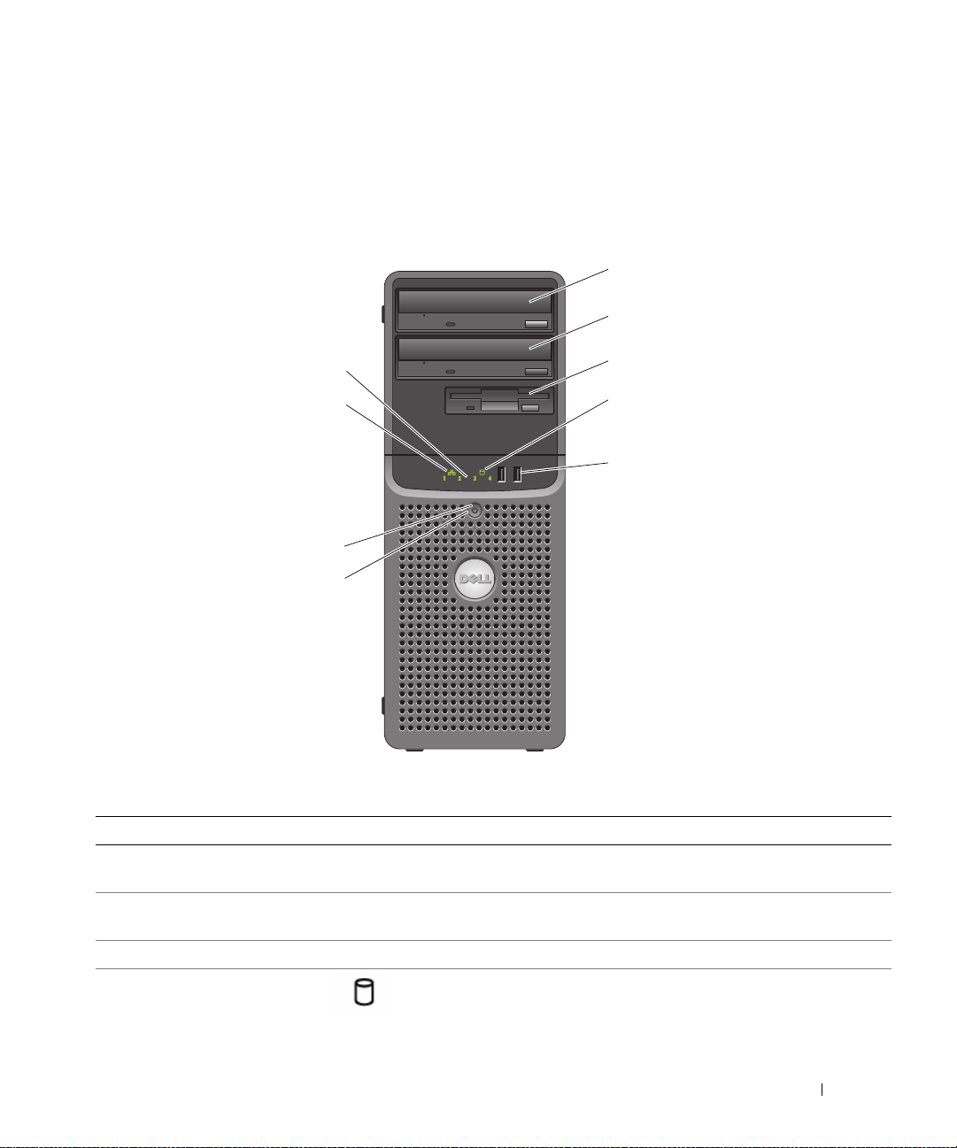
Front-Panel Features and Indicators
1
Figure 1-1 shows the controls, indicators, and connectors located on the system's front panel. Table 1-2
provides component descriptions.
Figure 1-1. Front-Panel Features and Indicators
2
9
8
7
6
Table 1-2. Front-Panel Components
Item Component Icon Description
1 upper 5.25-inch drive
bay
2 lower 5.25-inch drive
bay
3 flex bay Holds an optional diskette drive.
4 hard-drive activity
indicator
Holds an optical drive.
Holds an optional optical or tape backup unit drive.
Indicates hard drive activity.
3
4
5
About Your System 11
Page 12
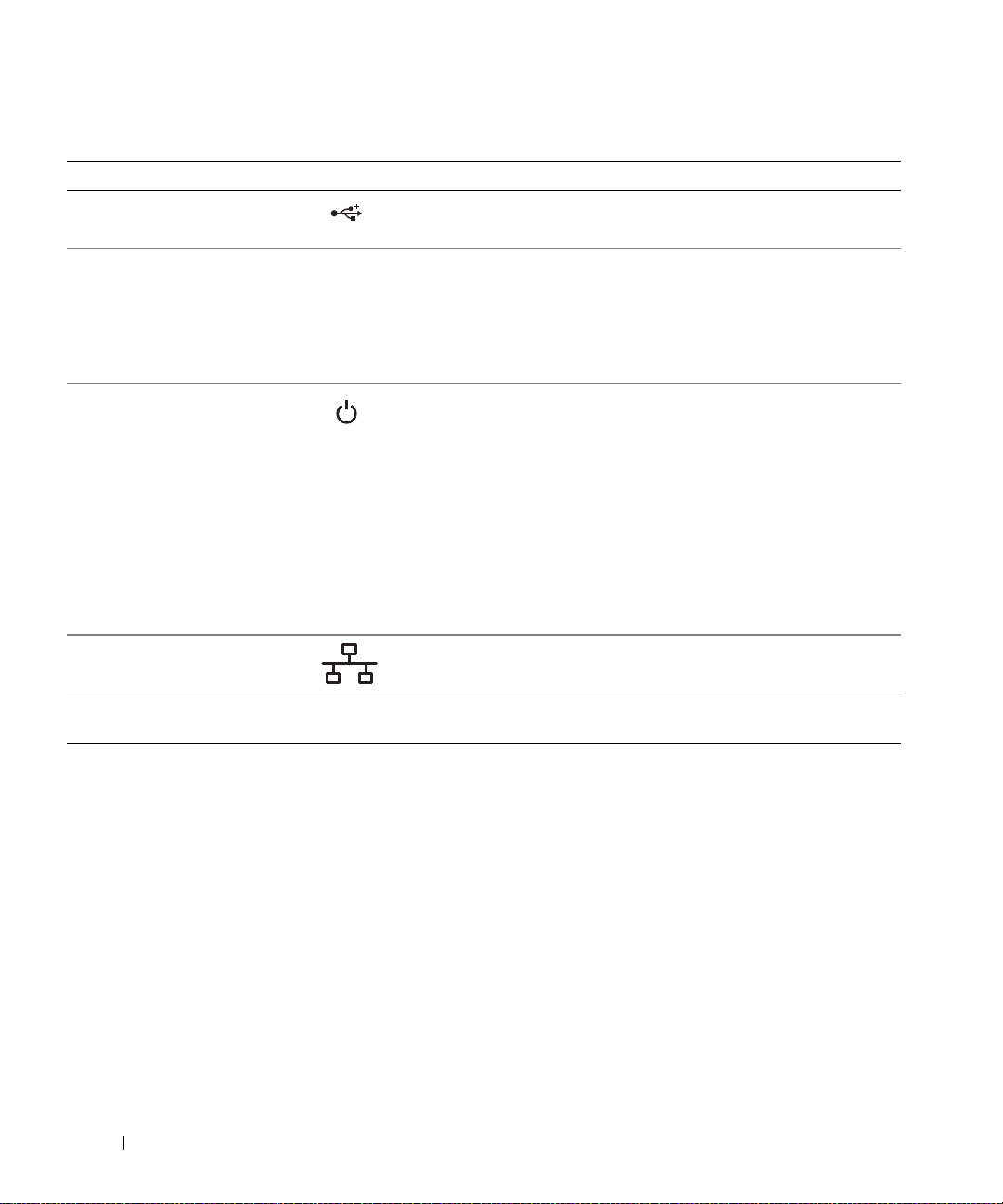
Table 1-2. Front-Panel Components (continued)
Item Component Icon Description
5 USB connectors (2) Connects USB 2.0-compliant devices to the system.
6 power button The power button controls the DC power supply output to the system.
NOTE: If you turn off the system using the power button and the system is
running an ACPI-compliant operating system, the system performs a
graceful shutdown before the power is turned off. If the system is not
running an ACPI-compliant operating system, the power is turned off
immediately after the power button is pressed.
7 power light No light — The system is off.
Steady green — The system is powered on.
Blinking green — The system is in a low power state.
Steady amber — The power supply is probably good.
Blinking amber — The system is powering up.
• If the hard drive indicator is off, the power supply may need to be
replaced.
• If the hard drive indicator is on, the system board is faulty. Check the
diagnostic indicators to see if the specific problem is identified. See
"Diagnostic Lights" on page 15.
8 network link light Lights when the system is linked to a network.
9 diagnostic lights (4) Display light-pattern codes to assist in troubleshooting system
problems.
See "Diagnostic Lights
" on page 15
.
12 About Your System
Page 13
Back-Panel Features and Indicators
Figure 1-2 shows the controls, indicators, and connectors located on the system's back panel.
Figure 1-2. Back-Panel Features and Indicators
1
2
3
4
5
6
7
1 voltage selection switch 2 power connector 3 NIC connector
4 USB connectors (5) 5 serial connector 6 video connector
7 I/O expansion-card slots (5)
Connecting External Devices
When connecting external devices to your system, follow these guidelines:
• Most devices must be connected to a specific connector and device drivers must be installed before the
device operates properly. (Device drivers are normally included with your operating system software or
with the device itself.) See the documentation that accompanied the device for specific installation
and configuration instructions.
About Your System 13
Page 14
• Always attach an external device while your system and the device are turned off. Next, turn on any
external devices before turning on the system (unless the documentation for the device specifies
otherwise).
See "Using the System Setup Program" on page 27 for information about enabling, disabling, and
configuring I/O ports and connectors.
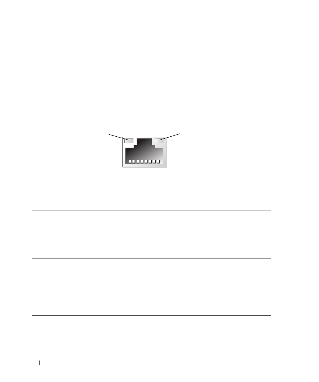
NIC Indicator Codes
The NIC on the back panel has an indicator that provides information on network activity and link
status. See Figure 1-3. Table 1-3 lists the NIC indicator codes.
Figure 1-3. NIC Indicators
1
1 link indicator 2 activity indicator
Table 1-3. NIC Indicator Codes
Indicator Type Indicator Code Description
Activity Off When off at the same time that the link indicator is off,
the NIC is not connected to the network or the NIC is
disabled in the System Setup program. See "Using the
System Setup Program" on page 27.
Blinking Indicates that network data is being sent or received.
Link Off When off at the same time that the activity indicator is
off, the NIC is not connected to the network or the NIC is
disabled in the System Setup program. See "Using the
System Setup Program" on page 27.
Yellow 1000-Mbps connection
Orange 100-Mbps connection
Green 10-Mbps connection
2
14 About Your System
Page 15
Power Supply Indicators
The voltage selection switch on the back panel of the system allows you to select one of two primary
voltage inputs. Ensure that the switch is set to the proper voltage according to Table 1-4.
Table 1-4. Voltage Selection Switch
If your power source is: The voltage selection switch should be set to:
110 V
220 V
115
230
For information on system power requirements, see "Technical Specifications" in your Getting Started
Guide.
Diagnostic Lights
The four diagnostic indicator lights on the system front panel display error codes during system startup.
Table 1-5 lists the causes and possible corrective actions associated with these codes. A highlighted circle
indicates the light is on; a non-highlighted circle indicates the light is off.
NOTE: Once the system completes POST, all diagnostic lights will be OFF.
Table 1-5. Diagnostic Indicator Codes
Code Causes Corrective Action
The computer is in a
normal off condition or a
possible pre-BIOS failure
has occurred.
The diagnostic lights are
not lit after the system
successfully boots to the
operating system.
Possible processor failure. See "Troubleshooting the Microprocessor" on
Plug the computer into a working electrical
outlet and press the power button.
page 95.
Memory failure. See "Troubleshooting System Memory" on
page 87.
Possible expansion card
failure.
See "Troubleshooting Expansion Cards" on
page 93.
About Your System 15
Page 16
Table 1-5. Diagnostic Indicator Codes (continued)
Code Causes Corrective Action
Possible video failure. See "Getting Help" on page 107.
Diskette drive or hard
drive failure.
Possible USB failure. See "Troubleshooting a USB Device" on
No memory modules
detected.
System board failure. See "Getting Help" on page 107.
Memory configuration
error.
Possible system board
resource and/or system
board hardware failure.
Possible system resource
configuration error.
Other failure. Ensure that the diskette drive, optical drive,
Ensure that the diskette drive and hard drive
are properly connected. See "Hard Drives" on
page 51 or "Diskette Drive" on page 44 for
information on the drives installed in your
system.
page 82.
See "Troubleshooting System Memory" on
page 87.
See "Troubleshooting System Memory" on
page 87.
See "Getting Help" on page 107.
See "Troubleshooting IRQ Assignment
Conflicts" on page 80. If the problem persists,
see "Getting Help" on page 107.
and hard drives are properly connected. See
"Troubleshooting Your System" on page 79 for
the appropriate drive installed in your system.
If the problem persists, see "Getting Help" on
page 107.
System Messages
System messages appear on the screen to notify you of a possible problem with the system. Table 1-6 lists
the system messages that can occur and the probable cause and corrective action for each message.
NOTE: If you receive a system message that is not listed in Table 1-6, check the documentation for the application
that is running when the message appears or the operating system's documentation for an explanation of the
message and recommended action.
16 About Your System
Page 17

CAUTION: Only trained service technicians are authorized to remove the system cover and access any of the
components inside the system. See your Product Information Guide for complete information about safety
precautions, working inside the computer, and protecting against electrostatic discharge.
Table 1-6. System Messages
Message Causes Corrective Actions
A filename cannot contain
any of the following
characters:
\ / : * ? “ < > |
A required .DLL file was
not found
Alert! CPU fan not
detected
Alert! Previous reboot was
due to voltage regulator
failure
Alert! System battery
voltage is low
Alert! Unable to initialize all installed memory
Alert! Card-cage fan
failure.
Alert! Chipset heat sink
not detected.
Alert! Cover was
previously removed.
The application that you are trying to
open is missing an essential file.
The processor cooling fan is faulty or
the fan assembly is not installed
correctly.
One or more memory modules might
be faulty or improperly seated.
A card-cage fan is not detected during
POST. The system will halt at the
<F1>/<F2> prompt even if
Keyboard Errors Report option is
disabled in the System Setup
program.
The system was opened. Information only. To reset the chassis
Do not use these characters in filenames.
Remove and then reinstall the
application.
See the application’s documentation for
installation instructions.
Ensure that the processor cooling fan is
properly installed. See "Troubleshooting
System Cooling Problems" on page 86.
See "Getting Help" on page 107.
Replace the battery. See
"Troubleshooting the System Battery" on
page 85.
See "Troubleshooting System Memory"
on page 87.
If the problem persists, see "Getting
Help" on page 107.
See "Troubleshooting System Cooling
Problems" on page 86.
Ensure heatsink and shroud assembly are
properly attached. See Figure 3-15.
intrusion switch, see "Using the System
Setup Program" on page 27.
About Your System 17
Page 18

Table 1-6. System Messages (continued)
Message Causes Corrective Actions
Alert! CPU fan failure. The processor cooling fan is faulty or
the fan assembly is not installed
correctly.
Alert! Error initializing
PCI Express slot n (or
bridge).
Alert! Incompatible
processor detected.
Alert! OS Install Mode
enabled. Amount of
available memory limited
to 256MB.
Alert! Previous fan
failure.
Alert! Previous attempts
at booting this system
have failed at checkpoint
[nnnn]. For help in
resolving this problem,
please note this
checkpoint and contact
Dell Technical Support.
Alert! Previous Processor
Thermal Failure
The system encountered a problem
while trying to configure a PCIe
expansion card.
The OS Install Mode option in the
System Setup program is set to On.
This limits the amount of available
memory to 256 MB because some
operating systems will not complete
installation with more than 2 GB of
system memory.
The fan caused errors the last time the
system was used.
The system failed to complete the
boot routine three consecutive times
for the same error.
The processor overheated the last
time the system was used.
Ensure that the processor cooling shroud
is properly installed. See
"Troubleshooting System Cooling
Problems" on page 86 and
"Microprocessor" on page 62.
See "Troubleshooting Expansion Cards"
on page 93.
Use only Dell supported processors. See
the Getting Started Guide for a list of
supported processors.
After the operating system is installed,
enter the System Setup program and set
the OS Install Mode option to Off. See
"Using the System Setup Program" on
page 27.
Ensure that nothing is blocking the
airflow vents and that all fans are
properly installed and operating
correctly. See "Troubleshooting System
Cooling Problems" on page 86.
See "Getting Help" on page 107.
Ensure that nothing is blocking the
airflow vents and that all fans are
properly installed and operating
correctly. Also, ensure that the processor
heat sink is properly installed. See
"Microprocessor" on page 62.
18 About Your System
Page 19

Table 1-6. System Messages (continued)
Message Causes Corrective Actions
Alert! Previous Shutdown
Due to Thermal Event
Alert! Uncorrectable
Memory Error Previously
Detected... Address
XXXXXXXX
Attachment failed to
respond
Bad command or file name Ensure that you have spelled the
Bad error-correction code
(ECC) on disk read
bb/dd/f
IRQ for PCI Device
bb/dd/f
I/O BAR for PCI Device
bb/dd/f
Mem BAR for PCI Device
bb/dd/f
PMem BAR for PCI Device
bb/dd/f
UMB for PCI Device
NOTE:
device number, and
number. All numbers are hexadecimal.
Controller has failed The hard drive or the associated
H, Device DIMM_
: Error allocating
: Error allocating
: Error allocating
: Error allocating
: Error allocating
bb
is the bus number, dd is the
f
is the function
The processor or hard drive
overheated the last time the system
was used.
One or more memory modules might
be improperly seated or faulty, or the
system board may be faulty.
Y
The diskette or hard-drive controller
cannot send data to the associated
drive.
The diskette or hard-drive controller
detected an uncorrectable read error.
The system encountered a problem
while trying to configure an expansion
card or integrated on-board devices.
controller is defective.
Ensure that nothing is blocking the
airflow vents and that all fans are
working correctly. Also, ensure that the
processor heat sink is properly installed.
See "Microprocessor" on page 62.
See "Troubleshooting System Memory"
on page 87.
If the problem persists, see "Getting
Help" on page 107.
See "Troubleshooting a Diskette Drive"
on page 89 or "Troubleshooting a Hard
Drive" on page 91.
command correctly, have put spaces in
the proper place, and have used the
correct pathname.
See "Troubleshooting a Diskette Drive"
on page 89 or "Troubleshooting a Hard
Drive" on page 91.
If the device number points to an
expansion card, the card can be removed.
See "Troubleshooting Expansion Cards"
on page 93.
If the device number points to a an onboard device, disable the device. See
"Using the System Setup Program" on
page 27.
See "Troubleshooting a Hard Drive" on
page 91.
About Your System 19
Page 20

Table 1-6. System Messages (continued)
Message Causes Corrective Actions
Data error The diskette drive or hard drive
cannot read the data.
Decreasing available
memory
Diskette drive 0 seek
failure
Diskette read failure The diskette might be defective, or a
Diskette subsystem reset
failed
Diskette write protected The diskette is write-protected. Slide the write-protect notch to the open
Drive not ready No diskette is in the drive. Insert a diskette in the drive.
Error auto-sensing primary
master hard disk drive
Error auto-sensing primary
slave hard disk drive
Error auto-sensing
secondary master hard disk
drive
Error auto-sensing
secondary slave hard disk
drive
Floppy diskette seek
failure
Gate A20 failure Faulty keyboard controller (faulty
One or more memory modules might
be faulty or improperly seated.
A cable might be loose or the system
configuration information might not
match the hardware configuration.
cable might be loose.
The diskette drive controller might be
faulty.
A diskette drive is not connected but
is enabled in the BIOS setup menu.
The diskette in the drive is faulty.
system board).
For the operating system, run the
appropriate utility to check the file
structure of the diskette drive or hard
drive. See your operating system
documentation for information on
running these utilities.
Reinstall the memory modules and, if
necessary, replace them. See
"Troubleshooting System Memory" on
page 87.
See "Troubleshooting a Diskette Drive"
on page 89.
If the diskette-drive indicator turns on,
try a different disk. See "Troubleshooting
a Diskette Drive" on page 89.
Run the system diagnostics. See
"Running the System Diagnostics" on
page 98.
position.
See "Troubleshooting a Hard Drive" on
page 91.
See "Troubleshooting a Diskette Drive"
on page 89.
See "Getting Help" on page 107.
20 About Your System
Page 21

Table 1-6. System Messages (continued)
Message Causes Corrective Actions
General failure The operating system is unable to
carry out the command.
Hard-disk configuration
error
Hard-disk controller
failure
Hard-disk drive failure
x
Drive
(or Parallel) ATA, SATA(or PATA-)
NOTE:
and
Insert bootable media The operating system is trying to boot
Invalid configuration
information - please run
SETUP program
Keyboard Controller
Failure
Keyboard Stuck Key Failure
Keyboard failure
Keyboard fuse has failed. See "Troubleshooting the Keyboard" on
Memory address line
failure at
value
Memory allocation error The software you are attempting to
not found: Serial
n
x
is the drive number (0-6)
n
is SATA0-3 or PATA0-1.
address
expecting
value
, read
The hard drive failed initialization. Run the system diagnostics. See
from a nonbootable diskette or CD.
The system configuration information
does not match the hardware
configuration.
A cable or connector might be loose,
or the keyboard or keyboard/mouse
controller might be faulty.
A memory module might be faulty or
improperly seated.
run is conflicting with the operating
system, another program, or a utility.
This message is usually followed by
specific information. Take the
appropriate action to resolve the
problem.
"Running the System Diagnostics" on
page 97. Also, see "Troubleshooting a
Hard Drive" on page 91.
Run the system diagnostics. See
"Running the System Diagnostics" on
page 97. Also, see "Troubleshooting a
Hard Drive" on page 91.
Insert a bootable diskette or CD.
Enter the System Setup program and
correct the system configuration
information. See "Using the System
Setup Program" on page 27.
See "Troubleshooting the Keyboard" on
page 81.
page 81.
Reinstall the memory modules and, if
necessary, replace them. See
"Troubleshooting System Memory" on
page 87.
Turn off the system, wait 30 seconds,
restart the system, and then try to run
the program again. If the error message
appears again, see the software
documentation for additional
troubleshooting suggestions.
About Your System 21
Page 22

Table 1-6. System Messages (continued)
Message Causes Corrective Actions
Memory data line failure
address
at
expecting
Memory double word logic
failure at
value
Memory odd/even logic
failure at
value
Memory write/read failure
address
at
expecting
Memory size in CMOS
invalid
Memory type or speed is not
supported on this system.
Please refer to system
documentation for support
memory configurations.
NIC failure. See "Troubleshooting a NIC" on page 83.
No boot device available The system cannot find the diskette or
, read
value
address
expecting
address
expecting
, read
value
value
, read
value
, read
value
value
A memory module might be faulty or
improperly seated.
The amount of memory recorded in
the system configuration information
does not match the memory installed
in the system.
hard drive.
Reinstall the memory modules and, if
necessary, replace them. See
"Troubleshooting System Memory" on
page 87.
Restart the system. If the error message
appears again, see "Troubleshooting
System Memory" on page 87. If the
problem persists, see "Getting Help" on
page 107.
See "Troubleshooting System Memory"
on page 87.
If the diskette drive is your boot device,
ensure that a bootable disk is in the
drive.
If the hard drive is your boot device,
ensure that the hard drive is installed,
the interface cable is properly connected,
and the hard drive is partitioned as a
boot device.
Enter the System Setup program and
verify the boot sequence information.
See "Using the System Setup Program"
on page 27.
22 About Your System
Page 23

Table 1-6. System Messages (continued)
Message Causes Corrective Actions
No boot sector on
hard-disk drive
No timer tick interrupt A chip on the system board might be
Non-system disk or disk
error
Not a boot diskette The operating system is trying to boot
Not enough memory or
resources. Close some
programs and try again.
Mixing ECC and non-ECC
DIMMs is not supported on
this platform
The system configuration information
in the System Setup program might
be incorrect.
malfunctioning.
The diskette in the diskette drive or
your hard drive does not have a
bootable operating system installed
on it.
from a diskette that does not have a
bootable operating system installed
on it.
You have too many programs open. Close all windows and open the program
Enter the System Setup program and
verify the system configuration
information for the hard drive. See
"Using the System Setup Program" on
page 27.
If the message continues to appear after
verifying the information in the System
Setup program, the operating system
might have been corrupted.
operating system. See your operating
system documentation for reinstallation
information.
Run the system diagnostics. See
"Running the System Diagnostics" on
page 97.
Replace the diskette with one that has a
bootable operating system or remove the
diskette, and then restart the system.
If the problem persists, see
"Troubleshooting a Diskette Drive" on
page 89 or "Troubleshooting a Hard
Drive" on page 91.
If the problem persists, see "Getting
Help" on page 107.
Insert a diskette that has a bootable
operating system.
that you want to use. In some cases, you
might have to restart your system to
restore system resources. If so, try
opening the program that you want to
use first
See "Troubleshooting System Memory"
on page 87. If the problem persists, see
"Getting Help" on page 107.
Reinstall the
About Your System 23
Page 24

Table 1-6. System Messages (continued)
Message Causes Corrective Actions
Operating system not found See "Troubleshooting a Hard Drive" on
page 91. If the problem persists, see
"Getting Help" on page 107.
Please connect USB
keyboard/mouse to USB
ports on the back of the
computer
Plug and play
configuration error
Read fault The operating system cannot read
Requested sector not found The operating system cannot read
Reset failed The disk reset operation failed. See "Troubleshooting a Diskette Drive"
Sector not found
Seek error
Shutdown failure A chip on the system board might be
The amount of system
memory has changed
The file being copied is
too large for the
destination drive.
The keyboard and/or mouse is not
properly connected.
An attached device is improperly
configured.
from the diskette or hard drive, the
system could not find a particular
sector on the disk, or the requested
sector is defective.
from the diskette or hard drive, the
system could not find a particular
sector on the disk, or the requested
sector is defective.
A faulty diskette drive or hard drive. See "Troubleshooting a Diskette Drive"
malfunctioning.
Memory has been added or removed,
or a memory module may be faulty.
The file that you are trying to copy is
too large to fit on the disk.
See "Troubleshooting a USB Device" on
page 82.
See "Troubleshooting Your System" on
page 79.
See "Troubleshooting a Diskette Drive"
on page 89 or "Troubleshooting a Hard
Drive" on page 91.
See "Troubleshooting a Diskette Drive"
on page 89 or "Troubleshooting a Hard
Drive" on page 91.
on page 89 or "Troubleshooting a Hard
Drive" on page 91.
on page 89 or "Troubleshooting a Hard
Drive" on page 91.
Run the system diagnostics. See
"Running the System Diagnostics" on
page 97.
If memory has been added or removed,
this message is informative and can be
ignored. If memory has not been added
or removed, check the SEL to determine
if single-bit or multi-bit errors were
detected and replace the faulty memory
module. See "Troubleshooting System
Memory" on page 87.
Try increasing disk space on the
destination drive by deleting
unnecessary files.
24 About Your System
Page 25

Table 1-6. System Messages (continued)
Message Causes Corrective Actions
Time-of-day clock stopped The battery might be faulty. See "Troubleshooting the System
Battery" on page 85.
Time-of-day not set The time or date stored in the System
Setup program does not match the
system clock.
Timer chip counter 2
failed
Unexpected interrupt in
protected mode
Write fault
Write fault on selected
drive
<drive letter>
accessible. The device is
not ready.
:\ is not
A chip on the system board might be
malfunctioning.
The operating system cannot write to
the diskette drive or hard drive.
The diskette drive cannot read the
diskette.
Enter the System Setup program and
correct the Date and Time options. See
"Using the System Setup Program" on
page 27. If the problem persists, see
"Troubleshooting the System Battery" on
page 85.
Run the system diagnostics. See
"Running the System Diagnostics" on
page 97.
Run the system diagnostics. See
"Running the System Diagnostics" on
page 97.
See "Troubleshooting a Diskette Drive"
on page 89 or "Troubleshooting a Hard
Drive" on page 91.
Insert a diskette into the drive or replace
the existing diskette, and try again.
Warning Messages
A warning message alerts you to a possible problem and prompts you to respond before the system
continues a task. For example, before you format a diskette, a message will warn you that you may lose all
data on the diskette. Warning messages usually interrupt the task and require you to respond by typing
(yes) or
n (no).
NOTE: Warning messages are generated by either the application or the operating system. For more information,
see the documentation that accompanied the operating system or application.
About Your System 25
y
Page 26

Diagnostics Messages
When you run system diagnostics, an error message may result. Diagnostic error messages are not
covered in this section. Record the message on a copy of the Diagnostics Checklist in "Getting Help" on
page 107, and then follow the instructions in that section for obtaining technical assistance.
Alert Messages
Systems management software generates alert messages for your system. Alert messages include
information, status, warning, and failure messages for drive, temperature, fan, and power conditions. For
more information, see the systems management software documentation.
26 About Your System
Page 27

Using the System Setup Program
After you set up your system, run the System Setup program to familiarize yourself with your system
configuration and optional settings. Record the information for future reference.
You can use the System Setup program to:
• Change the system configuration stored in NVRAM after you add, change, or remove hardware
• Set or change user-selectable options—for example, the time or date
• Enable or disable integrated devices
• Correct discrepancies between the installed hardware and configuration settings
Entering the System Setup Program
During System Setup
1
Turn on or restart your system.
2
Press <F2> immediately after you see the following message:
<F2> = System Setup
If your operating system begins to load before you press <F2>, allow the system to finish booting,
and then restart your system and try again.
NOTE: To ensure an orderly system shutdown, see the documentation that accompanied your operating
system.
Responding to Error Messages
You can enter the System Setup program by responding to certain error messages. If an error message
appears while the system is booting, make a note of the message. Before entering the System Setup
program, see "System Messages
correcting errors.
NOTE: After installing a memory upgrade, it is normal for your system to send a message the first time you
start your system.
" on page 16
for an explanation of the message and suggestions for
Navigating the System Setup Program
Table 2-1 lists the keys that you use to view or change information on the System Setup screens, and to
exit the program.
Using the System Setup Program 27
Page 28

Table 2-1. System Setup Program Navigation Keys
Keys Action
Up arrow and down arrow Moves to the previous or next field
Left arrow and right arrow Moves left or right in a field
<+> and <–> keys Opens and closes submenus
<Enter> Allows you to view the details for or modify an option,
or allows you to confirm your setting change and moves
the cursor back to the option menu
<Esc> Either moves your cursor back to the option menu
without modifying an option, or opens the System
Setup
Exit
screen
NOTE: For most of the options, any changes that you make are recorded but do not take effect until you restart the
system.
Exiting the System Setup Program
If you have made no changes in the BIOS, the
<Esc> to exit the System Setup program:
•
Remain in Setup
•
Exit
If you have made changes in the BIOS, the
Exit
to exit the System Setup program:
•
Remain in Setup
•
Save/Exit
•
Discard/Exit
System Setup Options
Main Screen
Figure 2-1 shows an example of the main screen.
Exit
screen displays the following options after you press
screen displays the following options after you press <Esc>
28 Using the System Setup Program
Page 29
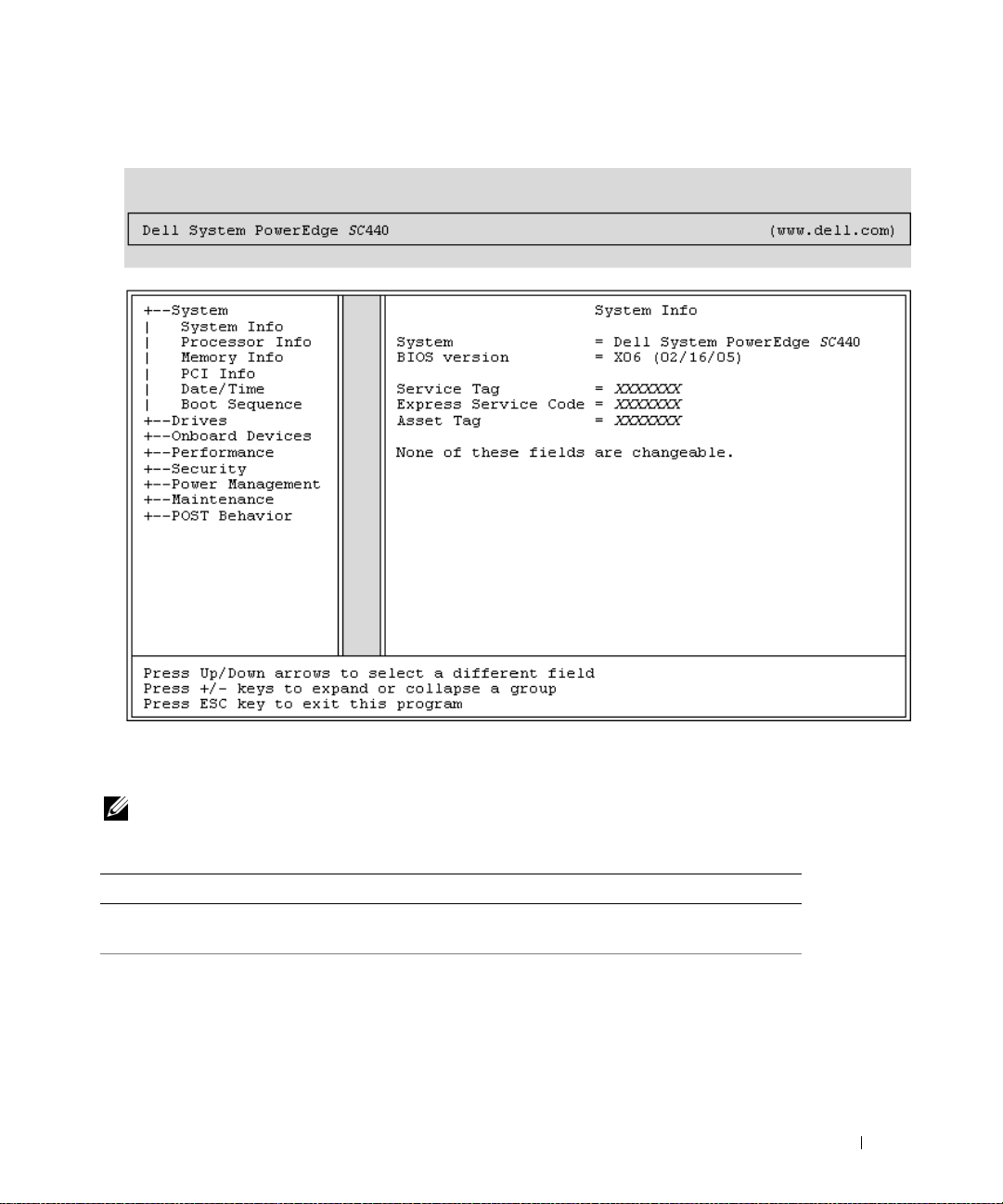
Figure 2-1. Main System Setup Program Screen
Table 2-2 through Table 2-9 lists the options and descriptions for each group of information fields that
appear on the main System Setup program screen.
NOTE: The System Setup program defaults are listed under their respective options, where applicable.
Table 2-2. System Options
Option Description
System Info
Processor Info
Displays the
Express Service Code
Displays the following information for the processor installed in the system:
Processor Type, Processor Clock Speed, Processor Bus Speed, Processor
Cache Size, Processor ID
Capable
Technology
System
name,
BIOS Version
, and
Asset Tag
number, whether the processor is
, or
Hyperthreading Capable
.
number,
.
, and if the processor has
BIOS Date, Service Tag,
Using the System Setup Program 29
Multiple Core
64-bit
Page 30

Table 2-2. System Options (continued)
Option Description
Memory Info
PCI Info
Date/Time
Boot Sequence
(Diskette drive default)
Table 2-3. Drive Options
Option Description
Diskette Drive
(Internal default)
Displays the amount of
Channel Mode
also displays a table that describes the memory size, whether the memory
module is ECC capable, single or dual rank, type, and organization for each
DIMM socket.
Displays the types of cards that are installed in the PCI slots, if applicable.
Resets the system’s internal calendar and clock.
Determines the order in which the system searches for boot devices during
system startup. Available options can include the diskette drive, CD drive,
hard drives, and USB devices.
Enables and disables the diskette drives and sets read permission for the
internal diskette drive.
internal diskette drive and enables a USB drive if the USB controller is
enabled and a USB drive is connected.
diskette drive.
the internal diskette drive read-only permission.
NOTE: Diskette drives are optional and may not be part of your system.
SATA0-3
PATA 0- 1
SMART Reporting
(Off default)
Enables or disables a
device (such as hard drive, CD drive, or DVD drive).
interface so that the device cannot be used.
that the device can be used.
Displays the Controller type, Port number the drive is using, Drive ID
number, Capacity, whether the drive is controlled by the BIOS, and Link
Speed.
Enables or disables a
(such as hard drive or IDE drive).
device cannot be used.
used.
Displays the Controller type, Port number the drive is using, Drive ID
number, Capacity, whether the drive is controlled by the BIOS, and Link
Speed.
Determines whether hard-drive errors for internal drives are reported during
system startup.
Installed Memory, Memory Speed, Memory
, and a description of the
Off
disables all diskette drives.
Read Only
Off
enables the internal drive controller and allows
Serial Advanced Technology Attachment (S
Parallel Advanced Technology Attachment
On
enables the interface so that the device can be
does not report errors. On reports errors.
Memory Technology
Internal
enables the internal
On
enables the interface so
Off
disables the interface so that the
USB
disables the
Off
disables the
. This option
ATA)
device
30 Using the System Setup Program
Page 31

Table 2-4. Onboard Devices Options
Option Description
Integrated NIC
(On default)
Enables or disables the integrated Network Interface Controller (NIC).
disables the controller.
controller with PXE.
NOTE: PXE or RPL is required only if you are booting to an operating system
on another system, not if you are booting to an operating system on a hard
drive in this system.
USB Controller
(On default)
Enables or disables the internal USB controller. Off disables the
controller. On enables the controller. No Boot enables the controller, but
disables the ability to boot from a USB device.
NOTE: Operating systems with USB support will recognize USB storage
devices regardless of the No Boot setting.
Front USB Ports
(On default)
Enables or disables the front USB ports independently of the rear ports.
disables the controller.
controller, but disables the ability to boot from a USB device.
NOTE: Operating systems with USB support will recognize USB storage
devices regardless of the No Boot setting.
Serial Port #1
(Auto default)
Serial Port 1 options are COM1, COM3, Auto, and Off.
When serial port 1 is set to Auto, the integrated port automatically maps
to the next available port. Serial port 1 attempts to use COM1 first and
then COM3. If both addresses are in use for a specific port, the port is
disabled. When serial port is set to COM1, the integrated port is
configured at 3F8h with IRQ4. When the serial port is set to COM3, the
integrated port is configured at 3E8h with IRQ4.
If you set the serial port to Auto and add an expansion card with a port
configured to the same designation, the system automatically remaps the
integrated port to the next available port designation that shares the
same IRQ setting.
On
enables the controller.
On w/RPL
On
enables the controller with RPL.
enables the controller.
On w/PXE
No Boot
enables the
Off
enables the
Off
Table 2-5. Performance Options
Option Description
Hyper-Threading
(On default)
Multiple CPU Core
(On default)
Determines whether the physical processor appears as one or two logical
processors. The performance of some applications improve with
additional logical processors installed. On enables hyperthreading. Off
disables hyperthreading.
If the processor has multiple cores, specifies whether the processor will
have one or two cores enabled. The performance of some applications
will improve with the additional core. Off disables Multiple CPU Core
Technology. On enables Multiple CPU Core Technology.
Using the System Setup Program 31
Page 32

Table 2-5. Performance Options (continued)
Option Description
Limit CPUID Limits the maximum value the processor standard CPUID function will
support. Some operating systems will not complete installation when the
maximum CPUID is greater than 3.
Speed Step
(Off default)
HDD Acoustic Mode
(Performance default)
Table 2-6. Security Options
Option Description
Unlock Setup If the admin password has not been set, this option is not visible. If the
Admin Password
(Not Set default)
If the processor supports Enhanced Speed Step Technology, specifies
whether the option is Off or On.
NOTICE: Before enabling the Speed Step option, ensure that the
operating system also supports Enhanced Speed Step Technology.
Enabling the feature on operating systems that do not support it may
cause unpredictable results. See the operating system’s
documentation for its supported features.
Allows you to optimize IDE-drive performance and noise level based on
personal preferences. Bypass is used for older drives. Quiet slows drive
performance but reduces drive noise. Suggested adjusts performance to
the manufacturers preferred mode. Performance increases drive
performance but may increase drive noise.
admin password has been set, this option displays the current status of
your system password. Temporarily unlock setup by entering your admin
password.
Displays the current status of your System Setup program’s password
security feature and allows you to verify and assign a new admin password.
NOTE: See "Using the Admin Password" on page 37 for instructions on
assigning a setup password and using or changing an existing setup
password.
System Password
(Not Set default)
Displays the current status of your system's password security feature and
allows you to verify and assign a new system password.
NOTE: See "Using the System Password" on page 35 for instructions on
assigning a system password and using or changing an existing system
password.
Password Changes
(Unlocked default)
Determines the interaction between the System password and the Admin
password. Locked prevents a user with a valid System password from
being able to modify the System password. Unlocked allows a user with a
valid System password to modify the System password.
32 Using the System Setup Program
Page 33

Table 2-6. Security Options (continued)
Option Description
Chassis Intrusion
(On-Silent default)
Intrusion Alert If an intrusion has been detected, press the <Enter> key to acknowledge
Execute Disable
(On default)
Table 2-7. Power Management Options
Option Description
AC Recovery
(Last default)
Auto Power On
(Off default)
Auto Power Time Determines the time that you want the system to turn on.
Low Power Mode
(Off default)
Enables or disables the chassis-intrusion detection feature. When set to
On-Silent, chassis intrusion is detected but no warning message is
reported during start-up. When set to On, this field displays
DETECTED when the chassis cover has been opened. Pressing any edit
key acknowledges the intrusion and arms the system to look for further
security breaches. Off disables the chassis-intrusion detection feature.
the intrusion and arm the system to look for further security breaches.
Specifies whether or not Execute Disable Memory Protection Technology
is On or Off.
Determines how the system responds when AC power is re-applied after a
power loss. Off commands the system to stay off when the power is reapplied. You must press the front-panel power button before the system
turns on. On commands the system to turn on when the power is reapplied. Last commands the system to return to the last power state the
system was in just before it was turned off.
Determines when to use the Auto Power Time setting to turn on the
system. Off commands the system to not use the Auto Power Time
feature. Everyday turns on the system every day at the time set in Auto
Power Time. We ek da ys turns on the system every day from Monday
through Friday at the time set in Auto Power Time.
On conserves more power by removing power from most hardware
features. Off conserves less power and removes power from fewer
hardware features.
NOTE: With this option set to On, the integrated NIC will be disabled when
the system is in the Hibernate or Off states. Only add-in NICs will be able to
wake the system remotely.
Remote Wake Up
(Off default)
Determines how the system is turned on remotely from the Suspend,
Hibernate, or Off states. Off disables the NIC from waking up the
system. On enables the NIC to wake up the system. On w/ Boot to NIC
enables the NIC to wake up the system and boot from the network.
NOTE: If you want the system to perform a Remote Wake Up, you must first
set Low Power Mode to Off.
Using the System Setup Program 33
Page 34

Table 2-8. Maintenance Options
Option Description
Service Tag Displays the system service tag. If the service tag is corrupted, the system
will prompt to enter the correct service tag upon entering the system
setup program.
SERR Message Controls the SERR message mechanism. By default, this feature is On.
NOTE: Some graphics cards require that the SERR message mechanism be
disabled.
Load Defaults Allows you to restore all System Setup options to their factory defaults.
Event Log Allows you to view the Event Log. Entries are marked R for Read and U
for Unread. Mark All Entries Read puts an R to the left of all the entries.
Clear Log clears the Event Log.
Table 2-9. POST Behavior Options
Option Description
Fast Boot
(On default)
Numlock Key
(On default)
POST Hotkeys
(Setup and Boot Menu
default)
Keyboard Errors
(Report default)
When enabled, this feature reduces system startup time by bypassing
some compatibility steps. Off does not skip any steps during system
startup. On starts the system more quickly.
Determines the functionality of the numeric keys on the right side of
your keyboard. Off commands the right keypad keys to function as
arrows. On commands the right keypad keys to function as numbers.
Determines whether the sign-on screen displays a message stating the
keystroke sequence that is required to enter the Setup program or the
Quickboot feature. Setup & Boot Menu displays both messages
(
F2=Setup and F11=Boot Menu). Setup displays the setup
message only (
message only (
When set to Report (enabled) and an error is detected during POST, the
BIOS will display the error message and prompt you to press <F1> to
continue or press <F2> to enter System Setup.
When set to Do Not Report (disabled) and an error is detected during
POST, the BIOS will display the error message and continue booting the
system.
F2=Setup). Boot Menu displays the Quickboot
F11=Boot Menu). None displays no message.
NOTE: When detected, some errors (such as CPU or PCI fan failure) will
display an error message and prompt you to press <F1> to continue, or
<F2> to enter the Setup Menu.
34 Using the System Setup Program
Page 35

Password Features
NOTICE: The password features provide a basic level of security for the data on your system. If your data requires
more security, use additional forms of protection, such as data encryption programs.
NOTICE: Anyone can access the data stored on your system if you leave the system running and unattended
without having a system password assigned or if you leave your system unlocked so that someone can disable the
password by changing a jumper setting.
Your system is shipped to you without the system password feature enabled. If system security is a concern,
operate your system only with system password protection.
To change or delete an existing password, you must know the password (see "Deleting an Existing System
Password" on page 36). If you forget your password, you cannot operate your system or change settings in the
System Setup program until a trained service technician changes the password jumper setting to disable the
passwords, and erases the existing passwords.
Password
" on page 104
.
Using the System Password
After a system password is assigned, only those who know the password have full use of the system. When
the
System Password
NOTE: If you have assigned an admin password (see "Using the Admin Password" on page 37), the system accepts
your admin password as an alternate system password.
Assigning a System Password
Before you assign a system password, enter the System Setup program and check the
option.
When a system password is assigned, the setting shown for the
shown for the
Changes
option is
disabled by a jumper setting, the system password is
password.
When a system password is not assigned and the password jumper on the system board is in the enabled
(default) position, the setting shown for the
field is
Unlocked
1
Verify that the
2
Highlight the
3
Type your new system password.
You can use up to 32 characters in your password.
option is
Set
, the system prompts you for the system password after the system starts.
Password Changes is Unlocked
Locked
, you cannot change the system password. When the system password feature is
. To assign a system password:
Password Changes
System Password
option and press <Enter>.
This procedure is described in "Disabling a Forgotten
System Password
System Password
option is
, you can change the system password. If the
Disabled
System Password
option is set to
, and you cannot change or enter a new system
option is
Unlocked
.
Not Set
and the
Set
. If the setting
Password
Password Changes
As you press each character key (or the spacebar for a blank space), a placeholder appears in the field.
Using the System Setup Program 35
Page 36

The password assignment is not case-sensitive. However, certain key combinations are not valid. If you
enter one of these combinations, the system beeps. To erase a character when entering your password,
press <Backspace> or the left-arrow key.
NOTE: To escape from the field without assigning a system password, press <Esc> at any time prior to
completing step 5.
4
Press <Enter>.
5
To confirm your password, type it a second time and press <Enter>.
6
Press <Enter> again to continue.
The setting shown for the
7
Save and exit the System Setup program and begin using your system.
Using Your System Password to Secure Your System
NOTE: If you have assigned an admin password (see "Using the Admin Password" on page 37), the system accepts
your admin password as an alternate system password.
System Password
changes to
Set
.
When the Password Status option is set to Unlocked, you have the option to leave the password security
enabled or to disable the password security.
To leave the password security enabled:
1
Turn on or reboot your system by pressing <Ctrl><Alt><Del>.
2
Type your password and press <Enter>.
When the
Password Status
option is set to
Locked
when you turn on or reboot your system, type your
password and press <Enter> at the prompt.
After you type the correct system password and press <Enter>, your system operates as usual.
If an incorrect system password is entered, the system displays a message and prompts you to re-enter your
password. You have three attempts to enter the correct password. After the third unsuccessful attempt, the
system displays an error message showing the number of unsuccessful attempts and that the system has
halted. You are prompted to shut down your system. This message can alert you to an unauthorized person
attempting to use your system.
Even after you shut down and restart the system, the error message continues to be displayed until the
correct password is entered.
NOTE: You can use the Password Changes option in conjunction with the System Password and Admin Password
options to further protect your system from unauthorized changes.
Deleting an Existing System Password
1
Enter the System Setup program.
2
Highlight the
3
Enter the old password, and press <Enter>.
System Password
option, and press <Enter> to access the system password window.
36 Using the System Setup Program
Page 37

4
Press <Enter> twice to enter a new blank password and to confirm the new blank password.
5
Press <Enter> again to continue.
The setting changes to
Changing an Existing System Password
1
Enter the System Setup program.
2
Highlight the
3
Enter the old password, and press <Enter>.
4
Enter a new password, and press <Enter>.
5
Enter the new password again to confirm the change, and press <Enter>.
6
Press <Enter> to continue.
System Password
The setting remains
Not Set
Set
.
option, and press <Enter> to access the system password window.
.
Using the Admin Password
Assigning an Admin Password
You can assign (or change) an admin password only when the
To assign an admin password:
1
Highlight the
2
Type your new admin password.
Admin Password
option and press <Enter>.
You can use up to 32 characters in your password.
Admin Password
option selected is
Not Set
.
As you press each character key (or the spacebar for a blank space), a placeholder appears in the field.
The password assignment is not case-sensitive. However, certain key combinations are not valid. If you
enter one of these combinations, the system beeps. To erase a character when entering your password,
press <Backspace> or the left-arrow key.
NOTE: To escape from the field without assigning a system password, press <Enter> to move to another field,
or press <Esc> at any time prior to completing step 5.
3
Press <Enter>.
4
To confirm your password, type it a second time and press <Enter>.
The setting shown for the
5
Save and exit the System Setup program and begin using your system.
Admin Password
changes to
Set
.
The next time you enter the System Setup program, the system prompts you for the admin password.
Using the System Setup Program 37
Page 38

A change to the
required). By entering the
Admin Password
System Password
option becomes effective immediately (restarting the system is not
, you can scroll through and view all the screens, but you cannot
make changes to the settings for which a lock graphic is displayed in the upper right corner of the option
window.
Operating With an Admin Password Set
If
Admin Password
is
Set
, you must enter the correct admin password before you can modify most of the
System Setup options. When you start the System Setup program, the program prompts you to enter a
password.
If you do not enter the correct password in three attempts, the system lets you view, but not modify, the
System Setup screens—with the following exception: if
through the
Password Changes
option, you can assign a system password (however, you cannot disable or
System Password
is not
Set
and is not locked
change an existing system password).
NOTE: You can use the Password Changes option in conjunction with the Admin Password option to protect the
system password from unauthorized changes.
Deleting an Existing Admin Password
1
Enter the System Setup program.
2
Highlight the
3
Enter the old password, and press <Enter>.
4
Press <Enter> twice to enter a new blank password and to confirm the new blank password.
5
Press <Enter> again to continue.
The setting changes to
Admin Password
Not Set
option, and press <Enter> to access the admin password window.
.
Changing an Existing Admin Password
1
Enter the System Setup program.
2
Highlight the
3
Enter the old password, and press <Enter>.
4
Enter a new password, and press <Enter>.
5
Enter the new password again to confirm the change, and press <Enter>.
6
Press <Enter> to continue.
The setting remains
Admin Password
Set
.
option, and press <Enter> to access the admin password window.
Disabling a Forgotten Password
See "Disabling a Forgotten Password" on page 104
38 Using the System Setup Program
.
Page 39

Installing System Components
This section describes how to install the following system components:
• Front drive bezel
• Diskette drive
• Optical and tape drives
• Hard drives
• Expansion cards
• SAS controller card
•Memory
• Microprocessor
• Cooling fans
• System battery
• Power supply
• Chassis intrusion switch
•Bezel
• I/O panel
• System board
Recommended Tools
You may need the following items to perform the procedures in this section:
• #2 Phillips screwdriver
•W
rist grounding stra
p
Installing System Components 39
Page 40

Inside the System
3
In Figure 3-1, the system cover is opened to provide an interior view of the system.
Figure 3-1. Inside the System
2
1
9
8
4
5
7
1 5.25-inch drive bays (2) 2 drive cage 3 power supply
4 system board 5 hard drives (2) 6 card cage fan
7 heatsink and shroud assembly 8 processor cooling fan 9 3.5-inch drive bay
6
The system board can accommodate one processor, five expansion cards, and four memory modules. The
hard drive bays provide space for up to two SAS or SATA hard drives. Drive bays in the front of the
system provide space for an optical drive, an optional tape drive or second optical drive, and an optional
diskette drive. A controller expansion card is required for SAS hard drives. Power is supplied to the
system board and internal peripherals through a single nonredundant power supply.
40 Installing System Components
Page 41

Opening the System
CAUTION: Only trained service technicians are authorized to remove the system cover and access any of the
components inside the system. Before performing any procedure, see your Product Information Guide for
complete information about safety precautions, working inside the computer and protecting against electrostatic
discharge.
1
Turn off the system and attached peripherals, and disconnect the system from the electrical outlet.
2
Press the power button to ground the system board.
3
If you have installed a padlock through the padlock ring on the back panel, remove the padlock.
4
Lay the system on its side as shown in Figure 3-2.
5
Open the system by sliding the cover release tab toward the rear of the system and lifting the cover off.
See Figure 3-2.
Closing the System
1
Ensure that all internal cables are connected and folded out of the way.
2
Ensure that no tools or extra parts are left inside the system.
3
Reinstall the system cover:
a
Insert the bottom edge of the cover into the bottom of the system chassis. See Figure 3-2.
b
Press down on the cover until the cover release tab snaps into place.
4
If applicable, install the padlock.
5
Reconnect the system to the electrical outlet, and turn on the system and attached peripherals.
After you open and close the cover, the chassis intrusion detector, if enabled, causes the following
message to appear on the screen at the next system start-up:
ALERT! Cover was previously removed.
6
To reset the chassis intrusion detector, press <F2> to enter the System Setup program. See "Using the
System Setup Program" on page 27.
NOTE: If a setup password has been assigned by someone else, contact your network administrator for
information on resetting the chassis intrusion detector.
Installing System Components 41
Page 42

Figure 3-2. Opening and Closing the System
1
1 release tab
Front Drive Bezel
The front drive bezel is the cover for the optional diskette and 5.25-inch drives. To remove or install a
drive, you must first remove the front drive bezel.
CAUTION: Only trained service technicians are authorized to remove the system cover and access any of the
components inside the system. Before performing any procedure, see your Product Information Guide for
complete information about safety precautions, working inside the computer and protecting against electrostatic
discharge.
Removing the Front Drive Bezel
1
Turn off the system and attached peripherals, and disconnect the system from the electrical outlet.
2
Open the system. See "Opening the System" on page 41.
NOTE: The sliding plate secures and releases the front drive bezel and helps to secure the drives.
42 Installing System Components
Page 43

3
Slide the lever on the sliding plate in the direction of the arrow until it releases the front drive bezel
from its side hinges. See Figure 3-3.
4
Carefully tilt the front drive bezel away from the chassis and lift it out as shown in Figure 3-3.
5
Close the system. See "Closing the System" on page 41.
Replacing the Front Drive Bezel
1
Slide the lever on the sliding plate in the direction of the arrow and fit the bezel into the chassis.
2
Snap the bezel into place and release the lever.
Figure 3-3. Removing and Replacing the Front Drive Bezel
2
3
1
1 front drive bezel 2 sliding plate 3 arrow on the sliding plate
Removing an Insert on the Front Drive Bezel
If you install a drive in the 3.5-inch or 5.25-inch drive bays, first remove the corresponding insert on the
front drive bezel. From the back of the bezel, squeeze the tabs on the end of the insert and rotate the
insert away from the bezel. See
Figure 3-4.
Installing System Components 43
Page 44

Replacing an Insert on the Front Drive Bezel
If you remove a drive in the 3.5-inch or 5.25-inch drive bays, replace the corresponding insert on the front
drive bezel. From the back of the bezel,
snap the other end of the insert into place. See
Figure 3-4. Removing and Replacing the Front Drive Bezel Insert
1
4
1 front drive bezel 2 insert tabs 3 drive bezel insert
4 screws for an optional
5.25-inch drive (3)
fit the tab on the end of the insert into the notch on the bezel
Figure 3-4.
2
3
and
Diskette Drive
The 3.5-inch drive bay supports an optional standard diskette drive.
Removing the Diskette Drive
CAUTION: Only trained service technicians are authorized to remove the system cover and access any of the
components inside the system. Before performing any procedure, see your Product Information Guide for
complete information about safety precautions, working inside the computer and protecting against electrostatic
discharge.
1
Turn off the system and attached peripherals, and disconnect the system from the electrical outlet.
2
Open the system. See "Opening the System" on page 41.
3
Remove the front drive bezel. See "Removing the Front Drive Bezel" on page 42.
4
Disconnect the power and data cables from the diskette drive. See Figure 3-5.
5
Slide the lever on the sliding plate in the direction of the arrow. See Figure 3-5.
6
Hold the lever in position and slowly pull the drive out of the bay.
44 Installing System Components
Page 45

Figure 3-5. Removing or Installing a Diskette Drive
4
3
2
1
1 arrow on the sliding plate 2 sliding plate 3 drive-stop tab
4 power cable to diskette
drive (P7)
7
If you are permanently removing the drive, replace the 3.5-inch insert on front drive bezel. See
"Replacing an Insert on the Front Drive Bezel" on page 44.
5 data cable to diskette drive 6 data cable to system board
5
6
connector (FLOPPY)
If you are replacing the diskette drive, see "Installing a Diskette Drive" on page 45.
8
Replace the front drive bezel. See "Replacing the Front Drive Bezel" on page 43.
9
Close the system. See "Closing the System" on page 41.
10
Reconnect the system to the electrical outlet, and turn on the system and attached peripherals.
Installing a Diskette Drive
CAUTION: Only trained service technicians are authorized to remove the system cover and access any of the
components inside the system. Before performing any procedure, see your Product Information Guide for
complete information about safety precautions, working inside the computer and protecting against electrostatic
discharge.
1
Turn off the system and attached peripherals, and disconnect the system from the electrical outlet.
2
Open the system. See "Opening the System" on page 41.
Installing System Components 45
Page 46

3
Unpack the replacement diskette drive, and prepare it for installation.
4
Check the documentation for the drive to verify that it is configured for your system.
5
Remove the front drive bezel. See "Removing the Front Drive Bezel" on page 42.
6
Remove the 3.5-inch insert on the front drive bezel. See "Removing an Insert on the Front Drive Bezel"
on page 43.
7
Remove the four shoulder screws from the back of the insert. See Figure 3-4; the 3.5-inch insert holds
four screws.
8
Attach the four screws to the diskette drive as shown in Figure 3-6.
Figure 3-6. Installing Diskette Drive Shoulder Screws
1
1 screws (4)
9
Verify that the drive-stop tab on the drive cage is in the proper position. It should be in its lowermost
position so that the diskette icon on the drive cage is visible. See Figure 3-5.
NOTE: Inserting a diskette drive into the drive bay with the drive-stop tab in the improper position will cause the
drive to be positioned too deep in the bay.
10
From the front of the chassis, slide the drive into the drive bay until the shoulder screws snap securely
into the sliding plate.
11
Connect the P7 power cable to the drive. See Figure 3-5.
12
Connect the data cable from the drive to the diskette drive connector (FLOPPY) on the system board.
See Figure 3-5 and Figure 6-2.
13
Replace the front drive bezel. See "Replacing the Front Drive Bezel" on page 43.
14
Close the system. See "Closing the System" on page 41.
15
Reconnect the system to the electrical outlet, and turn on the system and attached peripherals.
16
Enter the System Setup program and ensure that the drive’s controller is enabled. See "Using the
System Setup Program" on page 27.
46 Installing System Components
Page 47

17
(Optional) Test the drive by running the system diagnostics. See "Running the System Diagnostics" on
page 97.
Optical and Tape Drives
In the upper 5.25-inch drive bay, you can install only an optical drive. In the lower 5.25-inch drive bay,
you can install either an optical or a tape backup unit.
Removing an Optical or Tape Drive
CAUTION: Only trained service technicians are authorized to remove the system cover and access any of the
components inside the system. Before performing any procedure, see your Product Information Guide for
complete information about safety precautions, working inside the computer and protecting against electrostatic
discharge.
1
Turn off the system and attached peripherals, and disconnect the system from the electrical outlet.
2
Open the system. See "Opening the System" on page 41.
3
Remove the front drive bezel. See "Removing the Front Drive Bezel" on page 42.
4
Disconnect the power and data cables from the back of the drive. See Figure 3-7.
5
Slide the lever on the sliding plate in the direction of the arrow to release the shoulder screw.
6
Slide the drive out to remove it from the drive bay.
Installing System Components 47
Page 48

Figure 3-7. Removing and Installing an Optical or Tape Drive
2
3
1
4
1 sliding plate 2 IDE data cable to drive 3 power cable to drive
4 IDE connector on system
board
7
If you are installing another drive in the bay, see "Installing an Optical or Tape Drive" on page 49.
8
If the drive is being permanently removed, install an insert on front drive bezel. See "Replacing an
Insert on the Front Drive Bezel" on page 44.
9
Replace the front drive bezel. See "Replacing the Front Drive Bezel" on page 43.
10
Close the system. See "Closing the System" on page 41.
11
Reconnect the system to the electrical outlet, and turn on the system and attached peripherals.
48 Installing System Components
Page 49

Installing an Optical or Tape Drive
CAUTION: Only trained service technicians are authorized to remove the system cover and access any of the
components inside the system. Before performing any procedure, see your Product Information Guide for
complete information about safety precautions, working inside the computer and protecting against electrostatic
discharge.
1
Unpack the drive and prepare it for installation. For instructions, see the documentation that
accompanied the drive.
If you are installing a SCSI tape drive, you must have a SCSI
an Expansion Card
" on page 57
) and configure the tape drive according to the documentation that
came with the tape drive, based on the following guidelines:
a
Each device attached to a SCSI host adapter must have a unique SCSI ID number (narrow SCSI
devices use IDs 0 to 7; wide SCSI devices use IDs from 0 to 15). Set the drive’s SCSI ID to avoid
conflicts with other devices on the SCSI bus. For the default SCSI ID setting, see the
documentation provided with the drive.
NOTE: There is no requirement that SCSI ID numbers be assigned sequentially or that devices be attached to
the cable in order by ID number.
SCSI logic requires that the two devices at opposite ends of a SCSI chain be terminated and that
b
all devices in between be unterminated. Therefore, you enable the tape drive’s termination if it is
the last device in a chain of devices (or sole device) connected to the SCSI controller.
2
Turn off the system, including any attached peripherals, and disconnect the system from the electrical
outlet.
3
Open the system. See "Opening the System" on page 41.
4
Remove the front drive bezel. See "Removing the Front Drive Bezel" on page 42.
5
If another drive is installed, remove it (see "Removing an Optical or Tape Drive" on page 47) and
remove the three shoulder screws to attach to the new drive (see Figure 3-8).
6
If the drive bay is empty, remove the insert on the front drive bezel. See "Removing an Insert on the
Front Drive Bezel" on page 43.
7
Remove the three shoulder screws from the insert, and attach them to the bottom row of holes on the
drive. See Figure 3-8.
controller card installed (see "Installing
Installing System Components 49
Page 50

Figure 3-8. Installing Optical or Tape Drive Shoulder Screws
1
1 screws (3)
8
Gently slide the drive into place until you hear a click or feel the drive securely installed.
9
Attach the power cable to the drive. See Figure 3-7.
10
Attach the data cable:
• If you are installing an IDE drive, another drive may be attached to the same data cable by another
connector. Connect the data cable to the IDE connector on the system board. See Figure 3-7.
• If you are installing a SCSI tape drive, connect the SCSI interface cable in the drive kit from the
SCSI controller card to the drive.
11
Check all cable connections, and fold cables out of the way to allow for airflow between the fan and
cooling vents.
12
Replace the front drive bezel. See "Replacing the Front Drive Bezel" on page 43.
13
Close the system. See "Closing the System" on page 41.
14
Reconnect the system to the electrical outlet, and turn on the system and attached peripherals.
15
If you installed an IDE drive, enter the System Setup program and ensure that the drive’s IDE
controller is enabled. See "Using the System Setup Program" on page 27.
16
(Optional) Test the drive by running the system diagnostics. See "Running the System Diagnostics" on
page 97.
50 Installing System Components
Page 51

Hard Drives
NOTE: The system’s drive configuration must consist of all SATA hard drives or all SAS hard drives.
Hard Drive Installation Guidelines
Your system contains up to two SATA or SAS hard drives in internal drive bays. Both drives must be
either SAS or SATA; mixed configurations are not supported. Up to two SATA drives may be connected
to the system’s integrated SATA controller or to an optional SAS controller expansion card. Up to two
SAS drives may be connected to an optional SAS controller expansion card. Table 3-1 describes the
possible drive configurations.
Table 3-1. Hard-Drive Configurations
Drive
Number
1 SATA HDD0 integrated SATA controller
1 SAS HDD0 SAS expansion card (slot 2) HDD0
2 SATA HDD1 integrated SATA
2 SAS HDD1 SAS expansion card (slot 2) HDD1
Drive Type Location Controller Connector
SATA0
SAS expansion card (slot 2)
SAS expansion card (slot 2)
HDD0
SATA2
HDD1
Removing a Hard Drive
CAUTION: Only trained service technicians are authorized to remove the system cover and access any of the
components inside the system. Before performing any procedure, see your Product Information Guide for
complete information about safety precautions, working inside the computer and protecting against electrostatic
discharge.
1
Turn off the system and attached peripherals, and disconnect the system from the electrical outlet.
2
Open the system. See "Opening the System" on page 41.
3
Disconnect the hard drive power cable from the hard drive that you are removing.
4
Disconnect the blue data cable from the hard drive that you are removing by pulling up on the blue
tab.
5
Press the blue tabs on each side of the hard-drive bracket toward each other and slide the drive up and
out of the bay. See Figure 3-9.
Installing System Components 51
Page 52

Figure 3-9. Removing and Installing a Hard Drive in the Drive Carrier
1
2
1 blue tabs (2) 2 hard drive in primary hard
drive bay
NOTE: If you do not intend to replace the drive, it is highly recommended that you remove the drive from the guide
bracket (see Figure 3-10) and insert the empty guide bracket back into the drive bay. This eliminates the likelihood
that the empty bracket will be misplaced or improperly stored while not in use.
6
Close the system. See "Closing the System" on page 41.
7
Reconnect the system to the electrical outlet, and turn on the system and attached peripherals.
3
3 secondary hard drive bay
Installing a Hard Drive
CAUTION: Only trained service technicians are authorized to remove the system cover and access any of the
components inside the system. Before performing any procedure, see your Product Information Guide for
complete information about safety precautions, working inside the computer and protecting against electrostatic
discharge.
1
Unpack the replacement hard drive and prepare it for installation.
2
Check the documentation for the hard drive to verify that the drive is configured for your system.
3
Turn off the system and attached peripherals, and disconnect the system from the electrical outlet.
4
Open the system. See "Opening the System" on page 41.
5
If you are replacing a hard drive, remove the drive that you are replacing (see "Removing a Hard Drive"
on page 51).
If there is a hard-drive bracket in the empty hard-drive bay, remove the bracket by pressing the two tabs
toward each other and pulling it up and out of the drive bay.
52 Installing System Components
Page 53

If a replacement hard drive does not have the hard-drive bracket attached, remove the bracket from the
old drive.
6
Snap the new drive into the guide bracket. See Figure 3-10.
7
Insert the guide bracket assembly into the drive bay until it snaps into place. See Figure 3-9.
Figure 3-10. Installing a Hard Drive in a Drive Bracket
1
2
1 hard drive 2 hard drive bracket
NOTICE: SAS drives and SATA drives cannot be mixed in the system. The drives must be either SATA or SAS hard
drives.
NOTE: The SAS controller card must be installed in PCIe SLOT2. See Figure 6-2.
8
Connect the power cable to the hard drive.
9
Connect the data cable to the hard drive:
• For connection to the integrated SATA controller (SATA hard drives only), connect the SATA data
cable to the SATA0 (first drive) and SATA2 (second drive) connectors on the system board. See
Figure 3-11. See Figure 6-2 for the location of the hard drive connectors on the system board.
• For connection to a SAS controller expansion card (SAS or SATA hard drives), connect the data
cable from the SAS controller card and the power cable as shown in Figure 3-12.
Controller Expansion Card
" on page 58
for instructions about installing the card and routing
See "SAS
the cables.
Installing System Components 53
Page 54

Figure 3-11. Cabling a SATA Hard Drive to the Integrated SATA Controller
1
2
3
1 SATA data cable to system
board
4 SATA data cable to hard drive
54 Installing System Components
4
2 power cable to hard drive 3 SATA hard drives (2)
Page 55

Figure 3-12. Cabling a SAS or SATA Hard Drive to a SAS Controller Expansion Card
1 2
7
3
4
5
6
1 SAS controller card 2 data cable to SAS controller
card
4 power cable to hard drive 5 SAS or SATA hard drives (2) 6 data cable to hard drive
7 hard drive activity indicator
cable to SAS controller card
10
Ensure that all connectors are properly cabled and firmly seated.
11
Close the system. See "Closing the System" on page 41.
12
Reconnect the system to the electrical outlet, and turn on the system and attached peripherals.
3 AUX_LED connector
See the documentation that came with the drive for instructions on installing any software required for
drive operation.
13
Press <F2> to enter the System Setup program (see "Entering the System Setup Program" on
page 27), and ensure that the drive’s controller is enabled.
14
Exit the System Setup program and reboot the system.
Installing System Components 55
Page 56

15
Partition and logically format the drive.
See the documentation for your operating system for instructions.
16
(Optional) Test the hard drive by running the system diagnostics. See "Running the System
Diagnostics" on page 97.
17
If the drive you just installed is the primary drive, install your operating system on the hard drive.
Expansion Cards
The system board can accommodate up to five expansion cards:
• two 5-V, half-length 32-bit, 33-MHz PCI (slots 3 and 5)
• one 2.5-Gb/sec PCIe x1 (slot 1)
• one 2.5-Gb/sec PCIe x4 (slot 4)
• one 2.5-Gb/sec PCIe x8 (slot 2)
See Figure 6-2 for the location of the expansion card slots.
NOTE: The size of the expansion card connectors for the PCI x4 card is PCIx 8, and for the PCI x8 card is PCI x16.
Removing an Expansion Card
CAUTION: Only trained service technicians are authorized to remove the system cover and access any of the
components inside the system. Before performing any procedure, see your Product Information Guide for
complete information about safety precautions, working inside the computer and protecting against electrostatic
discharge.
1
Turn off the system and attached peripherals, and disconnect the system from the electrical outlet.
2
Open the system. See "Opening the System" on page 41.
3
To open the card retention door, press the two release tabs inward. See Figure 3-13.
4
If necessary, disconnect any cables from the card.
5
Grasp the card by its top corners and ease it out of its connector.
6
If you are removing the card permanently, install a filler bracket in the empty card slot.
NOTE: Filler brackets must be installed over empty expansion card slots to maintain Federal Communications
Commission (FCC) certification of the system. The brackets also keep dust and dirt out of the system and aid in
proper cooling and airflow inside the system.
56 Installing System Components
Page 57

Figure 3-13. Removing and Installing an Expansion Card
1
2
3
4
5
1 release tabs (2) 2 card retention door 3 alignment bar
4 alignment guide 5 filler bracket
7
Close the card retention door to secure the remaining card(s) in the system. See Figure 3-13.
8
Close the system. See "Closing the System" on page 41.
9
Reconnect the system to the electrical outlet, and turn on the system and attached peripherals.
10
Remove the card’s device driver from the operating system.
Installing an Expansion Card
CAUTION: Only trained service technicians are authorized to remove the system cover and access any of the
components inside the system. Before performing any procedure, see your Product Information Guide for
complete information about safety precautions, working inside the computer and protecting against electrostatic
discharge.
1
Turn off the system and attached peripherals, and disconnect the system from the electrical outlet.
2
Open the system. See "Opening the System" on page 41.
Installing System Components 57
Page 58

3
To open the card retention door, press the two release tabs inward. See Figure 3-13.
4
If you are installing a new card, remove the filler bracket.
NOTE: Keep this bracket in case you need to remove the expansion card. Filler brackets must be installed
over empty expansion-card slots to maintain FCC certification of the system. The brackets also keep dust and
dirt out of the system and aid in proper cooling and airflow inside the system.
5
Prepare the card for installation.
See the documentation that came with the card for information on configuring the card, making
internal connections, or otherwise customizing it for your system.
NOTE: Some NICs automatically start the system when they are connected to a network.
6
Insert the card into the expansion card connector on the system board (SLOT1, SLOT2, SLOT3,
SLOT4, or SLOT5) and press down firmly. Ensure that the card is fully seated in the slot and all cards
and filler brackets are flush with the alignment bar.
See Figure 6-2 for the location of the five
expansion card connectors.
7
Close the card retention door to secure the card(s) in the system.
NOTICE: Do not route card cables over or behind the cards. Cables routed over the cards can prevent the system
cover from closing properly or cause damage to the equipment.
8
Connect any cables that should be attached to the card.
See the documentation for the card for information about the card’s cable connections.
9
Close the system. See "Closing the System" on page 41.
10
Reconnect the system to the electrical outlet, and turn on the system and attached peripherals.
11
Install any device drivers required for the card as described in the documentation for the card.
SAS Controller Expansion Card
Read the installation instructions in the documentation for your SAS controller card. Install the card in
expansion card connector SLOT2 (see "Installing an Expansion Card" on page 57), and connect the
hard-drive activity indicator cable from the card to the AUX_LED connector on the system board (see
Figure 6-2 for the connector location). See "Hard Drives" on page 51 for information about connecting
hard drives.
Memory
The four memory module connectors on the system board can accommodate from 512 MB to 4 GB of
533-MHz and 667-MHz unbuffered ECC DDR II single or dual-rank memory modules. See Figure 6-2
for the location of the four memory module connectors.
NOTE: As shown in Figure 6-2, memory slots are not in numeric order on the system board. When installing
memory, take care to install it in the proper slots according to the configuration guidelines in Table 3-2. Installing
memory in the wrong slots will significantly reduce system performance.
58 Installing System Components
Page 59

Memory Module Upgrade Kits
The system is upgradable to 4 GB by installing combinations of 512-MB and 1-GB 533-MHz or 667-MHz
unbuffered ECC DDR II single or dual-rank memory modules. You can purchase memory upgrade kits
from Dell.
Memory Module Installation Guidelines
• If only one memory module is installed, it must be installed in connector DIMM_1.
• If only one memory module is installed in connector DIMM_1, its capacity must be 512 MB.
• If more than one memory module is installed, the memory modules must be installed in pairs of
matched memory size, speed, and technology.
• Memory modules must be installed in ordered pairs in connectors DIMM_1 and DIMM_2, and then
DIMM_3 and DIMM_4.
• If a processor with a slower front-side bus rating than the memory is installed, the memory will operate
at the processor’s slower front-side bus speed.
NOTICE: If you remove your original memory modules from the system during a memory upgrade, keep them
separate from any new memory modules that you may have, even if you purchased the new memory modules from
Dell. Use only unregistered or unbuffered ECC DDR II memory modules.
Table 3-2 illustrates memory configuration guidelines. It is important to follow the slot installation
configurations shown here to achieve maximum memory performance.
Table 3-2. Memory Configuration Guidelines
Total Memory DIMM_1 DIMM_2 DIMM_3 DIMM_4
512 MB 512 MB none none none
1 GB 512 MB 512 MB none none
2 GB 512 MB 512 MB 512 MB 512 MB
2 GB 1 GB 1 GB none none
3 GB 1 GB 1 GB 512 MB 512 MB
4 GB 1 GB 1 GB 1 GB 1 GB
Addressing Memory With 4-GB Configurations (Microsoft® Windows® Operating System Only)
Your system supports a maximum of 4 GB of memory using four 1-GB memory modules. Current
operating systems can use a maximum of 4 GB of address space; however, the amount of memory
available to the operating system is slightly less than 4 GB.
NOTE: Depending on the type of PCI/PCIe expansion cards that are installed in your system, your system may only
support a maximum of 3.4 GB of memory or less.
Installing System Components 59
Page 60

The following components require address space:
• System ROM
• Advanced Programmable Interrupt Controllers (APIC)
• Integrated PCI devices (such as NICs) and SCSI controllers
• PCI expansion cards
At start-up, the BIOS identifies the components that require address space. The BIOS dynamically
calculates the amount of reserved address space required. The BIOS then subtracts the reserved address
space from 4 GB to determine the amount of usable space.
• If the total installed system memory is less than the usable space, all installed system memory is
available for use only by the operating system.
• If the total installed system memory is equal to or greater than the usable address space, a small
portion of installed memory is available for use by the operating system.
Removing a Memory Module
CAUTION: Only trained service technicians are authorized to remove the system cover and access any of the
components inside the system. Before performing any procedure, see your Product Information Guide for
complete information about safety precautions, working inside the computer and protecting against electrostatic
discharge.
1
Turn off the system and attached peripherals, and disconnect the system from the electrical outlet.
2
Open the system. See "Opening the System" on page 41.
3
Press out on the securing clip at each end of the memory module connector. See Figure 3-14.
4
Grasp the memory module and pull it out of the connector.
If the module is difficult to remove, gently move the module back and forth to remove it from the
connector.
Installing a Memory Module
CAUTION: Only trained service technicians are authorized to remove the system cover and access any of the
components inside the system. Before performing any procedure, see your Product Information Guide for
complete information about safety precautions, working inside the computer and protecting against electrostatic
discharge.
1
Turn off the system and attached peripherals, and disconnect the system from the electrical outlet.
2
Open the system. See "Opening the System" on page 41.
3
Press on the securing clip at each end of the memory module connector. See Figure 3-14.
4
Align the memory module’s edge connector with the alignment key in the connector.
The memory module connector has an alignment key that allows the memory module to be installed
in the connector in only one way.
60 Installing System Components
Page 61

5
Applying even pressure to both ends of the module, insert the module into the connector and carefully
press the module into place.
Figure 3-14. Installing and Removing a Memory Module
1
4
3
2
1 memory module 2 alignment key 3 socket
4 memory module socket
ejectors (2)
6
Pull up on the securing clips to lock the module into place.
If you insert the module correctly, the securing clips snap into the cutouts at each end of the module.
When the memory module is properly seated in the connector, the securing clips on the memory
module socket should align with the securing clips on the other connectors with memory modules
installed.
7
Close the system. See "Closing the System" on page 41.
8
Reconnect the system to the electrical outlet, and turn on the system and attached peripherals.
The system detects that the new memory does not match the existing configuration information and
generates the following message:
The amount of system memory has changed.
Strike the F1 key to continue, F2 to run the setup utility
Press <F2> to enter the System Setup program and check the value for
9
Memory Info
. See "System
Setup Options" on page 28.
The system should have changed the value for
Memory Info
to reflect the newly installed memory.
Verify the new value. If it is correct, skip to step 13.
10
If the memory value is incorrect, turn off the system and attached peripherals, and disconnect the
system from the electrical outlet.
Installing System Components 61
Page 62

11
Open the system. See "Opening the System" on page 41.
12
Ensure that the installed memory modules are seated properly in their connectors, and repeat step 7
through step 9.
13
When the
14
Run the system diagnostics to verify that the memory modules are operating properly. See "Running
the System Diagnostics" on page 98.
Memory Info
value is correct, press <Esc> to exit the System Setup program.
Microprocessor
You can upgrade the system processor to take advantage of future options in speed and functionality. The
processor and its associated internal cache memory are contained in a land grid array (LGA) package.
Removing the Processor
CAUTION: Only trained service technicians are authorized to remove the system cover and access any of the
components inside the system. Before performing any procedure, see your Product Information Guide for
complete information about safety precautions, working inside the computer and protecting against electrostatic
discharge.
CAUTION: The processor and heat sink can get very hot during normal operation. Ensure that they have had
sufficient time to cool before you touch them.
1
Turn off the system and attached peripherals, and disconnect the system from the electrical outlet.
2
Open the system. See "Opening the System" on page 41.
3
Using a #2 Phillips screwdriver, loosen the two captive screws holding the heat sink and shroud
assembly in place.
These captive screws are adjacent to the processor cooling fan housing. See Figure 3-15.
4
Tilt the heat sink and shroud assembly away from the fan housing and lift it out.
62 Installing System Components
Page 63

Figure 3-15. Installing and Removing the Heat Sink
1
3
4
1 heatsink and shroud assembly 2 assembly bracket 3 captive screws (2)
4 processor cooling fan
2
Installing System Components 63
Page 64

5
Open the processor cover by sliding the release lever from under the release lever latch on the socket.
Then, pull the lever back to release the processor. See Figure 3-16.
Figure 3-16. Installing and Removing a Processor
1
7
2
6
3
4
1 processor 2 retention latch 3 socket
4 release lever latch 5 tab 6 notched processor edge
7 release lever
NOTICE: The retention latch is pressure-loaded. Ensure that the latch does not quickly open and strike the
processor or system board.
6
Carefully pivot the retention latch away from the processor.
NOTICE: Do not pry the processor from the socket by a single edge. This could result in damage to the processor’s
delicate connections.
NOTICE: Be careful not to touch or drop any foreign materials on the socket connector pads.
7
Lift the processor straight up and out of the socket.
5
Leave the release lever and retention latch in the release position so that the socket is ready for the new
processor.
64 Installing System Components
Page 65

Replacing the Processor
1Unpack the new processor
2
Ensure that the contacts on the bottom of the replacement processor are free from dirt or other foreign
material.
3
Align the notched edge of the replacement processor with the tab on the processor frame. See
Figure 3-16.
NOTICE: Use caution when removing and installing the processor. Damaging the processor socket connectors
can damage the system board.
4
Carefully set the processor in the processor frame. Ensure that the notched edge of the processor fits
securely over the matching tab on the processor frame. Do not press down on the processor. If the
processor is seated correctly, it should fit snugly in the socket frame. See Figure 3-16.
5
Lower the retention latch onto the processor, and then rotate the release lever latch back toward the
system board until it snaps into place.
6
Clean the thermal grease from the bottom of the heat sink.
NOTICE: Ensure that you apply new thermal grease. Applying new thermal grease is critical to ensuring proper
thermal bonding as well as optimal processor operation.
7
Apply new thermal grease to the top of the processor.
8
Place the heat sink assembly back onto the heat sink assembly bracket and tilt the heat sink assembly
down on the system board. See Figure 3-15.
9
Align the two captive screws properly with the system board, then tighten them to secure the heat sink
assembly to the system board.
10
Close the system. See "Closing the System" on page 41.
11
Reconnect the system to the electrical outlet, and turn on the system and attached peripherals.
.
Cooling Fans
The system contains two cooling fans, one for the processor and one for the card cage. Each contains a
shroud that is part of the cooling fan assembly. The fan and shroud are replaced as a unit.
NOTE: If you are removing the larger processor cooling fan, you must first remove the heat sink and shroud
assembly. See "Removing the Processor" on page 62 (however, do not remove the processor) and Figure 3-17.
Removing the Cooling Fans
CAUTION: Only trained service technicians are authorized to remove the system cover and access any of the
components inside the system. Before performing any procedure, see your Product Information Guide for
complete information about safety precautions, working inside the computer and protecting against electrostatic
discharge.
1
Turn off the system and attached peripherals, and disconnect the system from the electrical outlet.
2
Open the system. See "Opening the System" on page 41.
Installing System Components 65
Page 66

3
Disconnect the fan’s power cable from the system board. See Figure 3-17.
4
If you are removing the smaller card cage fan (see Figure 3-17):
a
Pull up on the single release tab that attaches the fan to the chassis.
b
Slide the fan toward the back panel and lift the fan out.
5
If you are removing the larger processor cooling fan (see Figure 3-17):
a
Remove the heat sink and shroud assembly. See "Removing the Processor" on page 62. Do not
remove the processor, however.
b
Press the release tab that attaches the processor cooling fan to the chassis.
c
Slide the fan toward the back panel and lift the fan out.
Figure 3-17. Removing and Installing the Cooling Fans
1
2
3
4
6
5
1 processor cooling fan 2 release tab for processor fan 3 connector for processor fan
(CPU_CAGE)
4 connector for card cage fan
(FAN_CARD_CAGE)
5 release tab for card cage fan 6 card cage fan
66 Installing System Components
Page 67

Replacing the Cooling Fans
1
Align the securing tabs on the replacement fan with the mounting holes in the system chassis.
2
Slide the fan toward the front panel until it snaps into place.
3
If you replaced the larger processor cooling fan, replace the heat sink and shroud assembly (see
"Removing the Processor" on page 62).
4
Reconnect the fan power cable to the system board.
5
Close the system. See "Closing the System" on page 41.
System Battery
A coin-cell battery maintains system configuration, date, and time information. The battery can last
several years.
To determine whether you need to replace the battery, see "Troubleshooting the System Battery" on
page 85.
You can operate your system without a battery; however, without a battery, the configuration information
is erased if the system is turned off or unplugged from the electrical outlet. In this case, you must enter
the System Setup program and reset the configuration options.
CAUTION: A new battery can explode if it is incorrectly installed. Replace the battery only with the same or
equivalent type recommended by the manufacturer. Discard used batteries according to the manufacturer’s
instructions.
Removing the System Battery
CAUTION: Only trained service technicians are authorized to remove the system cover and access any of the
components inside the system. Before performing any procedure, see your Product Information Guide for
complete information about safety precautions, working inside the computer and protecting against electrostatic
discharge.
1 Enter the System Setup program and record the option settings on the System Setup screens. See
"Using the System Setup Program" on page 27
Turn off the system, including any attached peripherals, and disconnect the system from the electrical
2
.
outlet.
3 Open the system. See
4
See
Figure 6-2
for the location of the system battery and then remove any cables that block access to
"Opening the System" on page 41
.
the battery.
NOTICE: If you use a blunt, nonconductive object to depress the tab next to the battery, be careful not to touch the
system board with the object. Ensure that the object is inserted between the battery and the tab before you attempt
to depress the tab. Do not pry out the battery. You may damage the system board by prying off the socket or by
breaking circuit traces on the system board.
Installing System Components 67
Page 68

5
Press the tab on the battery socket to release the battery, then lift the battery out of the socket. See
Figure 3-18.
Figure 3-18. Removing and Installing the System Battery
2
1
1 battery socket 2 system battery 3 tab
3
Installing the System Battery
1
Install the new battery with the "+" facing up, and press down until it snaps into place. See
Figure 3-18
2 Close the system. See
Reconnect the system to the electrical outlet and turn on the system and attached peripherals.
3
4
Enter the System Setup program to confirm that the battery operates properly.
Setup Program" on page 27
5
From the main screen, select
6
Re-enter any system configuration information that is no longer displayed on the System Setup
screens, and then exit the System Setup program.
7 To test the newly installed battery, see
After an hour, reconnect the system to a power source and turn it on.
8
9
Enter the System Setup program. If the time and date are still incorrect, see "Getting Help" on
page 107.
10
Properly dispose of the old battery. For more information, see your
.
"Closing the System" on page 41
.
See
"Using the System
.
System Time
to enter the correct time and date.
"Troubleshooting the System Battery" on page 85
Product Information Guide
.
.
68 Installing System Components
Page 69

Power Supply
Removing the Power Supply
CAUTION: Only trained service technicians are authorized to remove the system cover and access any of the
components inside the system. Before performing any procedure, see your Product Information Guide for
complete information about safety precautions, working inside the computer and protecting against electrostatic
discharge.
1
Turn off the system and attached peripherals, and disconnect the system from the electrical outlet.
2
Open the system. See "Opening the System" on page 41.
3
Depending on your system configuration, disconnect the following power cables:
• P1 and P2 to the system board
• P3 and P5 to the SATA or SAS drives
• P7 to the diskette drive
• P8, P9, and P10 to the optical and tape drives
NOTE: Note the routing of the DC power cables underneath the tabs in the system frame as you release the
tabs and remove the cables from the system board and drives. You must route these cables properly when
you replace them to prevent their being pinched or crimped.
4
Remove the heat sink and shroud assembly. Loosen the two captive screws holding the heat sink and
shroud assembly in place.
These captive screws are adjacent to the processor cooling fan housing. See Figure 3-15.
5
Tilt the heat sink and shroud assembly away from the fan housing and lift it out.
6
Remove the IDE, I/O panel, and SATA cables (if present) attached to the routing clamps on the side of
the power supply.
7
Using a #2 Phillips screwdriver, remove the four Phillips screws that secure the power supply to the
back panel.
8
Press the power-supply release tab down and slide the power supply toward the front of the system,
then lift it out of the system chassis. See Figure 3-19.
9
Remove the cable clamp and set it aside to attach to the new power supply.
Installing System Components 69
Page 70

Figure 3-19. Removing the Power Supply
1
2
3
4
1 power supply release tab 2 power supply 3 screws (4)
4 cable clamp
Installing the Power Supply
1
Attach the cable clamp to the new power supply.
2
Align the power supply mounting holes with the mounting holes on the back panel.
3
Slide the power supply toward the back panel until it snaps into place over the power-supply release
tab.
4
Using a #2 Phillips screwdriver, install the four Phillips screws that secure the power supply to the back
panel.
5
Reattach the IDE, I/O panel, and SATA cables (if present) to the routing clamp on the side of the
power supply.
6
Depending on your system configuration, connect the following power cables:
• P1 and P2 to the system board
• P3 and P5 to the SATA or SAS drives
70 Installing System Components
Page 71

• P7 to the diskette drive
• P8, P9, and P10 to the optical and tape drives
7
Close the system. See "Closing the System" on page 41.
Chassis Intrusion Switch
Removing the Chassis Intrusion Switch
CAUTION: Only trained service technicians are authorized to remove the system cover and access any of the
components inside the system. Before performing any procedure, see your Product Information Guide for
complete information about safety precautions, working inside the computer and protecting against electrostatic
discharge.
1
Turn off the system and attached peripherals, and disconnect the system from the electrical outlet.
2
Open the system. See "Opening the System" on page 41.
3
Disconnect the chassis intrusion switch cable from the INTRUDER connector on the system board.
See Figure 3-20.
4
Slide the chassis intrusion switch out of the securing bracket notch. See Figure 3-20.
5
Remove the switch and its attached cable from the system.
Installing System Components 71
Page 72

Figure 3-20. Removing and Installing the Chassis Intrusion Switch
1
2
3
1 chassis intrusion switch 2 securing bracket notch 3 INTRUDER connector
Installing the Chassis Intrusion Switch
1
Align the chassis intrusion switch with the securing bracket notch. See Figure 3-20.
2
Slide the switch into the securing bracket notch.
3
Connect the switch cable to the INTRUDER connector on the system board.
4
Close the system. See "Closing the System" on page 41.
5
Reconnect the system to the electrical outlet, and turn on the system.
72 Installing System Components
Page 73

Bezel (Service Only Parts Procedure)
Removing the Bezel
CAUTION: Only trained service technicians are authorized to remove the system cover and access any of the
components inside the system. Before performing any procedure, see your Product Information Guide for
complete information about safety precautions, working inside the computer and protecting against electrostatic
discharge.
1
Turn off the system and attached peripherals, and disconnect the system from the electrical outlet.
2
Open the system. See "Opening the System" on page 41.
3
Remove the heat sink and shroud assembly. See "Removing the Processor" on page 62. Do not remove
the processor, however.
4
Remove the large processor cooling fan. See "Removing the Cooling Fans" on page 65.
5
Remove the three bezel release screws. See Figure 3-21.
6
Slide the bezel toward the top of the system, then lift it outward.
Installing System Components 73
Page 74

Figure 3-21. Removing the Bezel
1
2
1 bezel release screws (3) 2 bezel
Replacing the Bezel
1
Align the bezel with the chassis frame and slide it into position.
2
Attach the three bezel release screws to secure the bezel to the system chassis. See Figure 3-21.
3
Replace the processor fan. See "Replacing the Cooling Fans" on page 67.
4
Reinstall the heat sink and shroud assembly. See "Replacing the Processor" on page 65.
5
Close the system. See "Closing the System" on page 41.
6
Reconnect the system to the electrical outlet, and turn on the system.
I/O Panel Assembly (Service Only Parts Procedure)
CAUTION: Only trained service technicians are authorized to remove the system cover and access any of the
components inside the system. Before performing any procedure, see your Product Information Guide for
complete information about safety precautions, working inside the computer and protecting against electrostatic
discharge.
74 Installing System Components
Page 75

Removing the I/O Panel Assembly
1
Turn off the system and attached peripherals, and disconnect the system from the electrical outlet.
2
Open the system. See "Opening the System" on page 41.
3
Remove the heat sink and shroud assembly. See "Removing the Processor" on page 62. Do not remove
the processor, however.
4
Remove the processor cooling fan. See "Removing the Cooling Fans" on page 65.
5
Remove the front bezel. See "Removing the Bezel" on page 73.
NOTICE: Carefully note the routing of each cable before you disconnect it, so that you are sure to re-route cables
correctly.
6
Disconnect the I/O panel ribbon cable from the I/O panel connector by pulling the yellow cable loop.
7
Remove the mounting screw holding the I/O panel assembly to the front chassis. See Figure 3-22.
8 Lift the I/O panel assembly out of the system.
Figure 3-22. Removing and Installing the I/O Panel Assembly
1
4
1 I/O panel assembly 2 I/O panel ribbon cable 3 holding tab on the chassis
4 screw on the I/O panel
2
3
Installing System Components 75
Page 76

Replacing the I/O Panel Assembly
CAUTION: Only trained service technicians are authorized to remove the system cover and access any of the
components inside the system. Before performing any procedure, see your Product Information Guide for
complete information about safety precautions, working inside the computer and protecting against electrostatic
discharge.
1
Fit the I/O panel assembly into the holding tab on the front of the chassis. See Figure 3-22.
2
Secure the I/O panel assembly by replacing the screw. See Figure 3-22.
3
Connect the I/O panel ribbon cable to the new I/O panel connector.
4
Replace the large processor cooling fan. See "Replacing the Cooling Fans" on page 67.
5
Replace the heat sink and shroud assembly. See "Replacing the Processor" on page 65.
NOTE: To prevent damaging the processor, clean the heat sink to remove any thermal grease and then apply fresh
thermal grease to the processor before installing the heat sink.
6
Close the system. See "Closing the System" on page 41.
7
Reconnect the system to the electrical outlet, and turn on the system.
System Board (Service Only Parts Procedure)
CAUTION: Only trained service technicians are authorized to remove the system cover and access any of the
components inside the system. Before performing any procedure, see your Product Information Guide for
complete information about safety precautions, working inside the computer and protecting against electrostatic
discharge.
CAUTION: The heat sink can get hot during operation. To avoid burns, ensure that the system has sufficient time
to cool before removing the system board.
Removing the System Board
1
Turn off the system and attached peripherals, and disconnect the system from the electrical outlet.
2
Open the system. See "Opening the System" on page 41.
3
Depending on your configuration, disconnect the following cables from the system board. See
Figure 6-2 for connector locations.
• Two power-supply cables from the POWER and 12VPOWER connectors
• Diskette data cable from the FLOPPY connector
• I/O panel cable from the FRONTPANEL connector
• 5.25-inch device data cable from the IDE connector
• Processor cooling fan cable from the FAN_CPU connector
• Card cage cooling fan cable from the FAN_CARD_CAGE connector
76 Installing System Components
Page 77

• SATA hard-drive data cable(s) from the SATA connector(s)
• Intrusion switch cable from the INTRUDER connector
4
Remove all expansion cards and any attached cables. See "Removing an Expansion Card" on page 56.
5
Remove all memory modules. See "Memory" on page 58.
NOTE: Record the memory-module socket locations to ensure proper reinstallation of the memory modules.
CAUTION: The processor and heat sink can become extremely hot. Allow sufficient time for the processor and
heat sink to cool before handling.
NOTICE: To prevent damaging the processor, do not pry the heat sink off of the processor.
6
Remove the processor. See "Removing the Processor" on page 62.
7
Using a #2 Phillips screwdriver, remove the eight system board mounting screws that secure the system
board to the chassis. See Figure 3-23.
8
Using a #2 Phillips screwdriver, remove the two processor heat sink pivot mount screws and remove
the pivot mount from the system board. See Figure 3-23. The heat sink pivot mount screws are green
and are longer than the system board mounting screws.
Figure 3-23. System Board Mounting Points
1
1 heat sink pivot mount
screws (2)
3
2 system board mounting
screws (8)
2
3 system board
Installing System Components 77
Page 78

9
Carefully route any loose cables away from the edges of the system board.
10
Gently slide the system board toward the front of the system, then lift the system board up and out of
the chassis.
Installing the System Board
1
After removing the old system board, lower the new system board into the chassis, aligning the I/O
ports on the system board with the I/O connector openings on the back panel of the chassis.
2
Using a #2 Phillips screwdriver, install the eight screws on the system board that secure it to the
chassis. See Figure 3-23.
3
Using a #2 Phillips screwdriver, attach the processor heat sink pivot mount to the system board. See
Figure 3-23.
NOTICE: To prevent damaging the processor, clean the heat sink to remove any thermal grease and then apply
fresh thermal grease to the processor before installing the heat sink.
4
Replace the processor, and the heat sink and shroud assembly. See "Replacing the Processor" on
page 65.
5
Install the memory modules in the same sockets from which they were removed. See "Installing a
Memory Module" on page 60.
6
Install the expansion cards and connect any cables. See "Installing an Expansion Card" on page 57.
7
Depending on your configuration, connect the following cables that you removed in "Removing the
System Board" on page 76. See Figure 6-2.
• Two power-supply cables to the POWER and 12VPOWER connectors
• If applicable, diskette data cable to the FLOPPY connector
• I/O panel cable to the FRONTPANEL connector
• 5.25-inch device data cable to the IDE connector
• Processor cooling fan cable to the FAN_CPU connector
• Card cage cooling fan cable to the FAN_CARD_CAGE connector
• SATA hard-drive data cable(s) to the SATA connector(s)
• Intrusion switch cable from the INTRUDER connector
8
Close the system. See "Closing the System" on page 41.
9
Reconnect the system to the electrical outlet, and turn on the system.
78 Installing System Components
Page 79

Troubleshooting Your System
Safety First—For You and Your System
To perform certain procedures in this document, you must remove the system cover and work inside
the system. While working inside the system, do not attempt to service the system except as
explained in this guide and elsewhere in your system documentation.
CAUTION: Only trained service technicians are authorized to remove the system cover and access any of
the components inside the system. Before performing any procedure, see your Product Information Guide for
complete information about safety precautions, working inside the computer and protecting against
electrostatic discharge.
Start-Up Routine
Look and listen during the system's start-up routine for the indications described in Table 4-1.
Table 4-1. Start-Up Routine Indications
Look/listen for: Action
A code displayed on the system diagnostic indicators. See "Diagnostic Lights" on page 15.
An error message displayed on the monitor. See "System Messages" on page 16.
The monitor's power indicator. See "Troubleshooting the Video Subsystem" on
page 81.
The keyboard indicators. See "Troubleshooting the Keyboard" on page 81.
The diskette drive activity indicator. See "Troubleshooting a Diskette Drive" on page 89.
The CD drive activity indicator. See "Troubleshooting an Optical Drive" on page 90.
The hard-drive activity indicator. See "Troubleshooting a Hard Drive" on page 91.
An unfamiliar constant scraping or grinding sound
when you access a drive.
See "Getting Help" on page 107.
Checking the Equipment
This section provides troubleshooting procedures for external devices attached to the system, such
as the monitor, keyboard, or mouse. Before you perform any of the procedures, see "Troubleshooting
External Connections" on page 80.
Troubleshooting Your System 79
Page 80

Troubleshooting IRQ Assignment Conflicts
Most PCI devices can share an IRQ with another device, but they cannot use an IRQ simultaneously. To
avoid this type of conflict, see the documentation for each PCI device for specific IRQ requirements.
Table 4-2 lists the IRQ assignments.
Table 4-2. IRQ Assignment Defaults
IRQ Line Assignment
IRQ0 System timer
IRQ1 Keyboard controller
IRQ2 Interrupt controller 1 to enable IRQ8 through IRQ15
IRQ3 Serial port 2 (COM2 and COM4)
IRQ4 Serial port 1 (COM1 and COM3)
IRQ5 Remote access controller
IRQ6 Diskette drive (optional) controller
IRQ8 Real-time clock
IRQ9 ACPI functions (used for power management)
IRQ10 Available
IRQ11 Available
IRQ13 Math coprocessor
IRQ14 IDE CD drive controller
IRQ15 Available
Troubleshooting External Connections
Loose or improperly connected cables are the most likely source of problems for the system, monitor, and
other peripherals (such as a printer, keyboard, mouse, or other external device). Ensure that all external
cables are securely attached to the external connectors on your system. See Figure 1-2 for the back-panel
connectors on your system.
80 Troubleshooting Your System
Page 81

Troubleshooting the Video Subsystem
Problem
• Monitor is not working properly.
Action
1
Check the system and power connections to the monitor.
2
Run the appropriate online diagnostic test. See "Using Dell PowerEdge Diagnostics" on page 97.
If the tests run successfully, the problem is not related to video hardware.
If the problem is not resolved, see "Getting Help" on page 107.
Troubleshooting the Keyboard
Problem
• System message indicates a problem with the keyboard.
• Keyboard is not functioning properly.
Action
1
Enter the System Setup program and ensure that the USB ports are enabled. See "Using the System
Setup Program" on page 27.
2
Examine the keyboard and its cable for signs of damage.
3
Swap the faulty keyboard with a working keyboard.
If the problem is resolved, replace the faulty keyboard. See "Getting Help" on page 107
.
Run the appropriate online diagnostic test. See "Using Dell PowerEdge Diagnostics" on page 97.
4
If the problem is not resolved, see "Getting Help" on page 107.
Troubleshooting the Mouse
Problem
• System message indicates a problem with the mouse.
• Mouse is not functioning properly.
Action
1
Run the appropriate online diagnostic test. See "Using Dell PowerEdge Diagnostics" on page 97.
If the test fails, continue to the next step.
Troubleshooting Your System 81
Page 82

2
Examine the mouse and its cable for signs of damage.
If the mouse is not damaged, go to step 4.
If the mouse is damaged, continue to the next step.
3
Swap the faulty mouse with a working mouse.
If the problem is resolved, replace the faulty mouse.
Enter the System Setup program and ensure that the USB port is enabled. See "Using the System
4
Setup Program" on page 27.
If the problem is not resolved,
see
"Getting Help" on page 107
See
"Getting Help" on page 107
.
.
Troubleshooting Basic I/O Problems
Troubleshooting a Serial Port
Problem
• Error message indicates a problem with a serial port.
• Device connected to a serial port is not operating properly.
Action
1
Enter the System Setup program and ensure that the serial port is enabled and configured correctly for
your application. See "Using the System Setup Program" on page 27.
2
If the problem is confined to a particular application, see the application documentation for specific
port configuration requirements that the program may require.
3
Run the appropriate online diagnostic test. See "Using Dell PowerEdge Diagnostics" on page 97.
If the tests run successfully but the problem persists, see "Getting Help" on page 107.
Troubleshooting a USB Device
Problem
• System message indicates a problem with a USB device.
• Device connected to a USB port is not operating properly.
Action
1
Enter the System Setup program and ensure that the USB ports are enabled. See "Using the System
Setup Program" on page 27.
2
Turn off the system and any USB devices.
3
Disconnect the USB devices, and connect the malfunctioning device to the other USB connector.
82 Troubleshooting Your System
Page 83

4
Turn on the system and the reconnected device.
If the problem is resolved, the USB connector might be defective.
If possible, swap the interface cable with a working cable.
5
See
If the problem is resolved, replace the interface cable.
6
Turn off the system and the USB device, and swap the device with a comparable device.
7
Turn on the system and the USB device.
If the problem is resolved, replace the USB device.
"Getting Help" on page 107
See
"Getting Help" on page 107
See
"Getting Help" on page 107
.
.
.
If the problem persists,
see
"Getting Help" on page 107
.
Troubleshooting a NIC
Problem
• NIC cannot communicate with network.
Action
1
Run the appropriate online diagnostic test. See "Using Dell PowerEdge Diagnostics" on page 97.
2
Check the appropriate indicator on the NIC connector.
• If the link indicator does not light, check all cable connections.
• If the activity indicator does not light, the network driver files might be damaged or missing.
Remove and reinstall the drivers if applicable. See the NIC's documentation.
• Change the autonegotiation setting, if possible.
• Use another connector on the switch or hub.
If you are using a NIC card instead of an integrated NIC, see the documentation for the NIC card.
3
Ensure that the appropriate drivers are installed and the protocols are bound. See the NIC's
documentation.
4
Enter the System Setup program and confirm that the NICs are enabled. See "Using the System Setup
Program" on page 27.
5
Ensure that the NICs, hubs, and switches on the network are all set to the same data transmission
speed. See the network equipment documentation.
6
Ensure that all network cables are of the proper type and do not exceed the maximum length.
If the problem persists,
see
"Getting Help" on page 107
.
Troubleshooting Your System 83
Page 84

Troubleshooting a Wet System
Problem
• Liquid spilled on the system.
• Excessive humidity.
Action
CAUTION: Only trained service technicians are authorized to remove the system cover and access any of the
components inside the system. Before performing any procedure, see your Product Information Guide for
complete information about safety precautions, working inside the computer and protecting against electrostatic
discharge.
1
Turn off the system and attached peripherals, and disconnect the system from the electrical outlet.
2
Open the system. See "Opening the System" on page 41.
3
Remove all expansion cards installed in the system. See "Removing an Expansion Card" on page 56.
4
Let the system dry thoroughly for at least 24 hours.
5
Close the system. See "Closing the System" on page 41.
6
Reconnect the system to the electrical outlet, and turn on the system and attached peripherals.
If the system does not start properly,
If the system starts properly, shut down the system and reinstall all of the expansion cards that you
7
removed. See "Installing an Expansion Card" on page 57.
8
Run the appropriate online diagnostic test. See "Using Dell PowerEdge Diagnostics" on page 97.
If the tests fail,
see
"Getting Help" on page 107
see
"Getting Help" on page 107
.
.
Troubleshooting a Damaged System
Problem
• System was dropped or damaged.
Action
CAUTION: Only trained service technicians are authorized to remove the system cover and access any of the
components inside the system. Before performing any procedure, see your Product Information Guide for complete
information about safety precautions, working inside the computer and protecting against electrostatic discharge.
1
Open the system. See "Opening the System" on page 41.
2
Ensure that the following components are properly installed:
• Expansion cards
• Power supply
84 Troubleshooting Your System
Page 85

•Fans
• Processors and heat sinks
• Optional installed drivers
• Memory modules
3
Ensure that all cables are properly connected.
4
Close the system. See "Closing the System" on page 41.
5
Run the system board tests in the system diagnostics. See "Running the System Diagnostics" on
page 97.
If the tests fail,
see
"Getting Help" on page 107
.
Troubleshooting the System Battery
Problem
• System message indicates a problem with the battery.
• System Setup program loses system configuration information.
• System date and time do not remain current.
NOTE: If the system is turned off for long periods of time (for weeks or months), the NVRAM may lose its system
configuration information. This situation is caused by a defective battery.
Action
1
Re-enter the time and date through the System Setup program. See "Using the System Setup Program"
on page 27.
2
Turn off the system and disconnect it from the electrical outlet for at least one hour.
3
Reconnect the system to the electrical outlet and turn on the system.
4
Enter the System Setup program. See "Using the System Setup Program" on page 27.
If the date and time are not correct in the System Setup program, replace the battery. See "System
Battery" on page 67.
see
If the problem is not resolved by replacing the battery,
NOTE: Some software may cause the system time to speed up or slow down. If the system seems to operate
normally except for the time kept in the System Setup program, the problem may be caused by software rather than
by a defective battery.
"Getting Help" on page 107
Troubleshooting Your System 85
.
Page 86

Troubleshooting Power Supply
Problem
• Power-supply fault indicator is blinking amber.
Action
CAUTION: Only trained service technicians are authorized to remove the system cover and access any of the
components inside the system. Before performing any procedure, see your Product Information Guide for
complete information about safety precautions, working inside the computer and protecting against electrostatic
discharge.
1
Turn off the system and attached peripherals, and disconnect the system from the electrical outlet.
2
Open the system. See "Opening the System" on page 41.
3
Check that the voltage selection switch on the back panel of the system is set properly. See "Power
Supply Indicators" on page 15.
NOTICE: Setting the voltage selection switch to an improper setting can damage your system.
4
Ensure that the power supply is properly installed by removing and reinstalling it. See "Installing the
Power Supply" on page 70.
NOTE: After installing a power supply, allow several seconds for the system to recognize the power supply
and to determine if it is working properly. The power indicator turns green to signify that the power supply is
functioning properly.
5
If the problem is resolved, close the system. See "Closing the System" on page 41.
If the problem persists, remove the faulty power supply. See "Removing the Power Supply" on page 69.
6
Install a new power supply. See "Installing the Power Supply" on page 70.
If the problem persists, see "Getting Help" on page 107.
Troubleshooting System Cooling Problems
Problem
• Systems management software issues a fan-related error message.
Action
Ensure that none of the following conditions exist:
• System cover, drive blank, or front or back filler panel is removed.
• Ambient temperature is too high.
• External airflow is obstructed.
86 Troubleshooting Your System
Page 87

• Cables inside the system obstruct airflow.
• An individual cooling fan is removed or has failed. See "Troubleshooting a Fan" on page 87.
Troubleshooting a Fan
Problem
• System-status indicator is amber.
• System message indicates a fan-related error message.
Action
CAUTION: Only trained service technicians are authorized to remove the system cover and access any of the
components inside the system. Before performing any procedure, see your Product Information Guide for
complete information about safety precautions, working inside the computer and protecting against electrostatic
discharge.
1
Run the appropriate diagnostic test. See "Using Dell PowerEdge Diagnostics" on page 97.
2
Turn off the system and attached peripherals, and disconnect the system from the electrical outlet.
3
Open the system. See "Opening the System" on page 41.
4
Ensure that the faulty fan's power cable is firmly attached to the fan power connector. See "Cooling
Fans" on page 65.
5
Close the system. See "Closing the System" on page 41.
6
Reconnect the system to its electrical outlet, and turn on the system and attached peripherals.
7
If the problem is not resolved, install a new fan. See "Cooling Fans" on page 65.
If the replacement fan is working properly, close the system. See "Closing the System" on page 41.
see
If the replacement fan does not operate,
"Getting Help" on page 107
Troubleshooting System Memory
Problem
• Faulty memory module.
• Faulty system board.
• Diagnostic indicator code indicates a problem with system memory.
.
Troubleshooting Your System 87
Page 88

Action
CAUTION: Only trained service technicians are authorized to remove the system cover and access any of the
components inside the system. Before performing any procedure, see your Product Information Guide for
complete information about safety precautions, working inside the computer and protecting against electrostatic
discharge.
1
Run the appropriate online diagnostic test. See "Using Dell PowerEdge Diagnostics" on page 97.
2
Turn off the system and attached peripherals, and then turn them on again.
If an error message does not appear, continue to the next step.
If an error message appears, go to step 11.
3
Enter the System Setup program and check the system memory setting. See "Using the System Setup
Program" on page 27.
If the amount of memory installed matches the system memory setting, go to step 11.
4
Turn off the system and attached peripherals, and disconnect the system from the electrical outlet.
5
Open the system. See "Opening the System" on page 41.
6
Ensure that the memory banks are populated correctly. See "Memory Module Installation Guidelines"
on page 59.
If the memory modules are populated correctly, continue to the next step.
7
Reseat the memory modules in their sockets. See "Installing a Memory Module" on page 60.
8
Close the system. See "Closing the System" on page 41.
9
Reconnect the system to its electrical outlet, and turn on the system and attached peripherals.
10
Enter the System Setup program and check the system memory setting. See "Using the System Setup
Program" on page 27. If the amount of memory installed still does not match the system memory
setting, proceed to the next step.
11
Turn off the system and attached peripherals, and disconnect the system from its electrical outlet.
12
Open the system. See "Opening the System" on page 41.
NOTE: Several configurations for the memory modules exist; see "Memory Module Installation Guidelines" on
page 59.
13
If a diagnostic test or error message indicates a specific memory module as faulty, swap or replace the
module. Otherwise, swap the memory module in socket 1 with a module of the same type and capacity
that is known to be good. See "Installing a Memory Module" on page 60.
14
Close the system. See "Closing the System" on page 41.
15
Reconnect the system to its electrical outlet, and turn on the system and attached peripherals.
16
As the system boots, observe any error message that appears and the diagnostic indicators on the front
of the system.
88 Troubleshooting Your System
Page 89

17
If the memory problem is still indicated, repeat step 11 through step 16 for each memory module
installed.
If the problem persists, see
"Getting Help
" on page 107.
Troubleshooting a Diskette Drive
Problem
• Error message indicates a diskette drive problem.
Action
CAUTION: Only trained service technicians are authorized to remove the system cover and access any of the
components inside the system. Before performing any procedure, see your Product Information Guide for
complete information about safety precautions, working inside the computer and protecting against electrostatic
discharge.
1
Enter the System Setup program and verify that the diskette drive is configured correctly. See "Using
the System Setup Program" on page 27.
2
Run the appropriate online diagnostic test. See "Using Dell PowerEdge Diagnostics" on page 97.
3
Turn off the system and attached peripherals, and disconnect the system from the electrical outlet.
4
Open the system. See "Opening the System" on page 41.
5
Ensure that the diskette drive interface cable is securely connected to the diskette drive and the system
board.
6
Ensure that a power cable is properly connected to the drive.
7
Close the system. See "Closing the System" on page 41.
8
Reconnect the system to the electrical outlet, and turn on the system and attached peripherals.
9
Run the appropriate online diagnostic test to see whether the diskette drive works correctly.
If the problem persists, continue with the following steps.
10
Turn off the system and attached peripherals, and disconnect the system from its electrical outlet.
11
Open the system. See "Opening the System" on page 41.
12
Remove all expansion cards installed in the system. See "Removing an Expansion Card" on page 56.
13
Close the system. See "Closing the System" on page 41.
14
Reconnect the system to the electrical outlet, and turn on the system and attached peripherals.
15
Run the appropriate online diagnostic test to see whether the diskette drive works correctly.
If the tests run successfully, an expansion card may be conflicting with the diskette drive logic, or an
expansion card may be faulty. Continue to the next step.
If the tests fail,
see
"Getting Help" on page 107.
Troubleshooting Your System 89
Page 90

16
Turn off the system and attached peripherals, and disconnect the system from the electrical outlet.
17
Open the system. See "Opening the System" on page 41.
18
Reinstall one of the expansion cards you removed in step 12. See "Installing an Expansion Card" on
page 57.
19
Close the system. See "Closing the System" on page 41.
20
Reconnect the system to the electrical outlet, and turn on the system and attached peripherals.
21
Run the appropriate online diagnostic test to see whether the diskette drive works correctly.
22
Repeat step 16 through step 21 until all expansion cards are reinstalled or one of the expansion cards
causes the tests to fail.
If the problem is not resolved,
see
"Getting Help" on page 107
.
Troubleshooting an Optical Drive
Problem
• System cannot read data from a CD or DVD in an optical drive.
• Optical drive indicator does not blink during boot.
Action
CAUTION: Only trained service technicians are authorized to remove the system cover and access any of the
components inside the system. Before performing any procedure, see your Product Information Guide for
complete information about safety precautions, working inside the computer and protecting against electrostatic
discharge.
1
Try using a different CD or DVD that you know works properly.
2
Enter the System Setup program and ensure that the drive’s IDE controller is enabled. See "Using the
System Setup Program" on page 27.
3
Run the appropriate online diagnostic test. See "Using Dell PowerEdge Diagnostics" on page 97.
4
Turn off the system and attached peripherals, and disconnect the system from the electrical outlet.
5
Open the system. See "Opening the System" on page 41.
6
Ensure that the interface cable is securely connected to the optical drive and to the controller.
7
Ensure that a power cable is properly connected to the drive.
8
Close the system. See "Closing the System" on page 41.
9
Reconnect the system to the electrical outlet, and turn on the system and attached peripherals.
see
If the problem is not resolved,
"Getting Help" on page 107
.
90 Troubleshooting Your System
Page 91

Troubleshooting an IDE Tape Drive
Problem
• System cannot read data from a tape in an IDE tape drive.
• Diagnostic indicators or system messages indicate a tape drive-related failure.
• Tape drive indicator (if applicable) does not blink during boot.
Action
CAUTION: Only trained service technicians are authorized to remove the system cover and access any of the
components inside the system. Before performing any procedure, see your Product Information Guide for
complete information about safety precautions, working inside the computer and protecting against electrostatic
discharge.
1
Try using a different tape that you know works properly.
If the problem persists, continue with the following steps.
2
Enter the System Setup program and ensure that the drive’s IDE controller is enabled. See "Using the
System Setup Program" on page 27.
3
Run the appropriate online diagnostic test. See "Using Dell PowerEdge Diagnostics" on page 97.
4
Turn off the system and attached peripherals, and disconnect the system from the electrical outlet.
5
Open the system. See "Opening the System" on page 41.
6
Ensure that the IDE interface cable is securely connected to the tape drive and to the IDE connector
on the system board.
7
Ensure that a power cable is properly connected to the drive.
8
Close the system. See "Closing the System" on page 41.
9
Reconnect the system to the electrical outlet, and turn on the system and attached peripherals.
If the problem is not resolved, see "Getting Help" on page 107.
Troubleshooting a Hard Drive
Problem
• Device driver error.
• One or more hard drives not recognized by the system.
Action
CAUTION: Only trained service technicians are authorized to remove the system cover and access any of the
components inside the system. Before performing any procedure, see your Product Information Guide for
complete information about safety precautions, working inside the computer and protecting against electrostatic
discharge.
Troubleshooting Your System 91
Page 92

NOTICE: This troubleshooting procedure can destroy data stored on the hard drive. Before you proceed, back up
all files on the hard drive.
1
Run the appropriate online diagnostics test. See "Using Dell PowerEdge Diagnostics" on page 97.
Depending on the results of the diagnostics test, proceed as needed through the following steps.
2
If you are experiencing problems with multiple hard drives, skip to step 5. For a problem with a single
hard drive, continue to the next step.
3
If your system has a SAS RAID controller, perform the following steps.
a
Restart the system and press <Ctrl><R> to enter the host adapter configuration utility program.
See the documentation supplied with the host adapter for information about the configuration
utility.
b
Ensure that the hard drive has been configured correctly for the RAID.
c
Exit the configuration utility and allow the system to boot to the operating system.
4
Ensure that the required device drivers for your SAS controller card or SAS RAID controller are
installed and are configured correctly. See the operating system documentation for more information.
5
Check the cable connections inside the system:
a
Turn off the system, including any attached peripherals, and disconnect the system from the
electrical outlet.
b
Open the system. See "Opening the System" on page 41.
c
Verify that the cable connections between the hard drive(s) and the drive controller are correct,
whether the connections are to the SATA connectors on the system board, a SAS expansion card,
or a SAS RAID controller. See "Hard Drives" on page 51.
d
Verify that the SAS or SATA cables are securely seated in their connectors.
e
Close the system. See "Closing the System" on page 41.
f
Reconnect the system to the electrical outlet, and turn on the system and attached peripherals.
If the problem persists,
see
"Getting Help" on page 107
.
Troubleshooting a SAS RAID Controller
NOTE: When troubleshooting a SAS RAID controller, also see the documentation for your operating system and
the controller.
Problem
• Error message indicates a problem with the SAS RAID controller.
• SAS RAID controller performs incorrectly or not at all.
92 Troubleshooting Your System
Page 93

Action
CAUTION: Only trained service technicians are authorized to remove the system cover and access any of the
components inside the system. Before performing any procedure, see your Product Information Guide for
complete information about safety precautions, working inside the computer and protecting against electrostatic
discharge.
1
Run the appropriate online diagnostic test. See "Using Dell PowerEdge Diagnostics" on page 97.
2
Enter the System Setup program and ensure that the SAS RAID controller is enabled. See "Using the
System Setup Program" on page 27.
3
Restart the system and press <Ctrl><C> for the installed controller card to enter the configuration
utility program.
See the controller's documentation for information about configuration settings.
4
Check the configuration settings, make any necessary corrections, and restart the system.
If the problem is not resolved, continue to the next step.
5
Turn off the system and attached peripherals, and disconnect the system from its electrical outlet.
6
Open the system. See "Opening the System" on page 41.
7
Ensure that the controller card is firmly seated into the system board connector. See "Installing an
Expansion Card" on page 57.
8
Verify that the cable connections between the hard drives and the SAS controller are correct. See "Hard
Drives" on page 51.
Ensure that the cables are firmly connected to the SAS controller and the hard drives.
9
Close the system. See "Closing the System" on page 41.
10
Reconnect the system to its electrical outlet, and turn on the system and attached peripherals. If the
problem persists,
see "Getting Help
" on page 107
.
Troubleshooting Expansion Cards
NOTE: When troubleshooting an expansion card, see the documentation for your operating system and the
expansion card.
Problem
• Error message indicates a problem with an expansion card.
• Expansion card performs incorrectly or not at all.
Troubleshooting Your System 93
Page 94

Action
CAUTION: Only trained service technicians are authorized to remove the system cover and access any of the
components inside the system. Before performing any procedure, see your Product Information Guide for
complete information about safety precautions, working inside the computer and protecting against electrostatic
discharge.
1
Run the appropriate online diagnostic test for the expansion card which is exhibiting issues. See "Using
Dell PowerEdge Diagnostics" on page 97. Follow any recommended actions provided by the
diagnostics. If the problem persists, go to the next step.
2
Turn off the system and attached peripherals, and disconnect the system from the electrical outlet.
3
Open the system. See "Opening the System" on page 41.
4
Ensure that each expansion card is firmly seated in its connector. See "Installing an Expansion Card"
on page 57.
5
Close the system. See "Closing the System" on page 41.
6
Reconnect the system to the electrical outlet, and turn on the system and attached peripherals.
If the problem persists, go to the next step.
7
Turn off the system and attached peripherals, and disconnect the system from the electrical outlet.
8
Open the system. See "Opening the System" on page 41.
9
Remove all expansion cards in the system. See "Removing an Expansion Card" on page 56.
NOTE: If your operating system is running off a disk controller card (such as a SAS controller card), do not
remove it.
10
Close the system. See "Closing the System" on page 41.
11
Reconnect the system to the electrical outlet, and turn on the system and attached peripherals.
12
Run the appropriate online diagnostic test for any item in the system that doesn’t require an expansion
card.
13
If the problem persists, run the appropriate online diagnostic test on each card. See "Using Dell
PowerEdge Diagnostics" on page 97.
a
Turn off the system and attached peripherals, and disconnect the system from the electrical outlet.
b
Open the system. See "Opening the System" on page 41.
c
Remove an expansion card. See "Removing an Expansion Card" on page 56.
d
Close the system. See "Closing the System" on page 41.
e
Reconnect the system to the electrical outlet, and turn on the system and attached peripherals.
f
Run the appropriate online diagnostic test.
If the tests fail, repeat step 13 for each expansion card until you are able to single out the faulty
expansion card.
If the tests fail for all expansion cards,
94 Troubleshooting Your System
see
"Getting Help" on page 107.
Page 95

Troubleshooting the Microprocessor
Problem
• Error message indicates a processor problem.
• Diagnostic indicator code indicates a problem with the processor or system board.
• A heat sink is not installed for the processor.
Action
CAUTION: Only trained service technicians are authorized to remove the system cover and access any of the
components inside the system. Before performing any procedure, see your Product Information Guide for
complete information about safety precautions, working inside the computer and protecting against electrostatic
discharge.
1
If possible, run the appropriate online diagnostics test. See "Using Dell PowerEdge Diagnostics" on
page 97.
2
Turn off the system and attached peripherals, and disconnect the system from the electrical outlet.
3
Open the system. See "Opening the System" on page 41.
4
Ensure that the processor and heat sink are properly installed. See "Replacing the Processor" on
page 65.
5
Close the system. See "Closing the System" on page 41.
6
Reconnect the system to the electrical outlet, and turn on the system and attached peripherals.
7
If possible, run the appropriate online diagnostic test. See "Running the System Diagnostics" on
page 97.
If the tests fail or the problem persists, continue to the next step.
8
Turn off the system and attached peripherals, and disconnect the system from the electrical outlet.
9
Open the system. See "Opening the System" on page 41.
10Replace
11
Close the system. See "Closing the System" on page 41.
12
Reconnect the system to the electrical outlet, and turn on the system and attached peripherals.
13
Run the appropriate online diagnostic test. See "Running the System Diagnostics" on page 97.
If the problem persists, the system board is faulty.
the processor. See "Replacing the Processor" on page 65.
S
ee "Getting Help" on page 107.
Troubleshooting Your System 95
Page 96

96 Troubleshooting Your System
Page 97

Running the System Diagnostics
If you experience a problem with your system, run the diagnostics before calling for technical assistance.
The purpose of the diagnostics is to test your system's hardware without requiring additional equipment
or risking data loss. If you are unable to fix the problem yourself, service and support personnel can use
diagnostics test results to help you solve the problem.
Using Dell PowerEdge Diagnostics
To assess a system problem, first use the online Dell® PowerEdge® Diagnostics. Dell PowerEdge
Diagnostics is a suite of diagnostic programs, or test modules, that include diagnostic tests on chassis
and storage components such as hard drives, physical memory, communications and printer ports,
NICs, CMOS, and more. If you are unable to identify the problem using the PowerEdge Diagnostics,
then use the system diagnostics.
The files required to run PowerEdge Diagnostics for systems running supported Microsoft
and Linux operating systems are available at
system. For information about using diagnostics, see the
support.dell.com
Dell PowerEdge Diagnostics User's Guide
and on the CDs that came with your
System Diagnostics Features
The system diagnostics provides a series of menus and options for particular device groups or devices.
The system diagnostics menus and options allow you to:
• Run tests individually or collectively.
• Control the sequence of tests.
• Repeat tests.
• Display, print, or save test results.
• Temporarily suspend testing if an error is detected or terminate testing when a user-defined error
limit is reached.
• View help messages that briefly describe each test and its parameters.
• View status messages that inform you if tests are completed successfully.
• View error messages that inform you of problems encountered during testing.
®
Windows®
.
Running the System Diagnostics 97
Page 98

When to Use the System Diagnostics
If a major component or device in the system does not operate properly, component failure may be
indicated. As long as the microprocessor and the system's input/output devices (monitor, keyboard, and
diskette drive) are functioning, you can use the system diagnostics to help identify the problem.
Running the System Diagnostics
The system diagnostics is run from the utility partition on your hard drive.
NOTICE: Use the system diagnostics to test only your system. Using this program with other systems may cause
invalid results or error messages. In addition, use only the program that came with your system (or an updated
version of that program).
1
As the system boots, press <F10> during POST.
2
From the utility partition main menu, select
Diagnostics
When you start the system diagnostics, a message is displayed stating that the diagnostics are initializing.
Next, the
the system diagnostics.
Diagnostics
NOTE: Before you read the rest of this section, start the system diagnostics so that you can see the utility on your
screen.
if you are troubleshooting memory.
menu appears. The menu allows you to run all or specific diagnostics tests or to exit
Run System Diagnostics
, or select
Run Memory
System Diagnostics Testing Options
Click the testing option in the
options.
Table 5-1. System Diagnostics Testing Options
Testing Option Function
Express Test Performs a quick check of the system. This option runs device tests
Extended Test Performs a more thorough check of the system. This test can take an
Custom Test Tests a particular device.
Information Displays test results.
Main Menu
that do not require user interaction. Use this option to quickly identify
the source of your problem.
hour or longer.
window. Table 5-1 provides a brief explanation of testing
Using the Custom Test Options
When you select
to select the device(s) to be tested, select specific options for testing, and view the test results.
98 Running the System Diagnostics
Custom Test
in the
Main Menu
window, the
Customize
window appears and allows you
Page 99

Selecting Devices for Testing
The left side of the
or by module, depending on the option you select. Click the
components. Click
its components, selects all of the components of the device for testing.
Customize
(+)
on any component to view the tests that are available. Clicking a device, rather than
window lists devices that can be tested. Devices are grouped by device type
(+)
next to a device or module to view its
Selecting Diagnostics Options
Use the
Diagnostics Options
•
Non-Interactive Tests Only
•
Quick Tests Only
run when you select this option.
•
Show Ending Timestamp
Test Iterations
•
•
Log output file pathname
— When checked, runs only the quick tests on the device. Extended tests will not
— Selects the number of times the test is run.
area to select how you want to test a device. You can set the following options:
— When checked, runs only tests that require no user intervention.
— When checked, time stamps the test log.
— When checked, enables you to specify where the test log file is saved.
Viewing Information and Results
The tabs in the
tabs are available:
Results
•
•
Errors
Help
•
•
Configuration
•
Parameters
Customize
— Displays the test that ran and the result.
— Displays any errors that occurred during the test.
— Displays information about the currently selected device, component, or test.
— If applicable, displays parameters that you can set for the test.
window provide information about the test and the test results. The following
— Displays basic configuration information about the currently selected device.
Running the System Diagnostics 99
Page 100

100 Running the System Diagnostics
 Loading...