

Page 1

Precision 3640 Tower
Service Manual
0.0.0.0
Regulatory Model: D24M
Regulatory Type: D24M004
May 2020
Rev. A00
Page 2

Notes, cautions, and warnings
NOTE: A NOTE indicates important information that helps you make better use of your product.
CAUTION: A CAUTION indicates either potential damage to hardware or loss of data and tells you how to avoid the
problem.
WARNING: A WARNING indicates a potential for property damage, personal injury, or death.
© 2020 Dell Inc. or its subsidiaries. All rights reserved. Dell, EMC, and other trademarks are trademarks of Dell Inc. or its subsidiaries. Other
trademarks may be trademarks of their respective owners.
Page 3

Contents
1 Working on your computer............................................................................................................ 6
Safety instructions.................................................................................................................................................................6
Before working inside your computer........................................................................................................................... 6
Safety precautions...........................................................................................................................................................7
Electrostatic discharge—ESD protection.................................................................................................................... 7
ESD field service kit ........................................................................................................................................................8
Transporting sensitive components.............................................................................................................................. 8
After working inside your computer.............................................................................................................................. 9
2 Technology and components........................................................................................................10
DDR4......................................................................................................................................................................................10
Intel Rapid Storage Technology (Intel RST)......................................................................................................................11
Advantages of DisplayPort over USB Type-C..................................................................................................................13
HDMI 2.0............................................................................................................................................................................... 13
3 Major components of your system................................................................................................15
4 Disassembly and reassembly........................................................................................................ 16
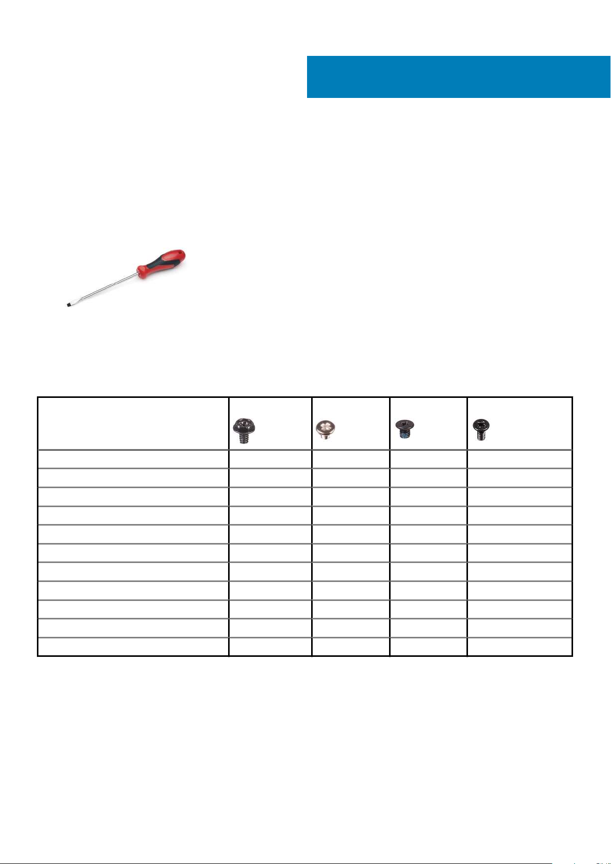
Recommended tools............................................................................................................................................................ 16
Screw list...............................................................................................................................................................................16
Chassis rubber feet..............................................................................................................................................................16
Removing the chassis rubber feet............................................................................................................................... 16
Installing the chassis rubber feet..................................................................................................................................18
Cover.....................................................................................................................................................................................20
Removing the cover......................................................................................................................................................20
Installing the cover......................................................................................................................................................... 21
SD card—optional...............................................................................................................................................................22
Removing the SD card .................................................................................................................................................22
Installing the SD card.................................................................................................................................................... 23
Bezel......................................................................................................................................................................................24
Removing the front bezel............................................................................................................................................. 24
Installing the front bezel............................................................................................................................................... 25
Hard drive.............................................................................................................................................................................25
Removing the 3.5-inch hard drive ..............................................................................................................................25
Installing the 3.5-inch hard drive ................................................................................................................................ 26
Removing the 2.5-inch hard drive .............................................................................................................................. 27
Installing the 2.5-inch hard drive ................................................................................................................................ 29
PSU hinge..............................................................................................................................................................................31
Opening the PSU hinge................................................................................................................................................. 31
Closing the PSU hinge.................................................................................................................................................. 32
Graphics card....................................................................................................................................................................... 33
Removing the graphics card........................................................................................................................................ 33
Installing the graphics card...........................................................................................................................................35
Memory module...................................................................................................................................................................38
Contents 3
Page 4

Removing the memory module.................................................................................................................................... 38
Installing the memory module...................................................................................................................................... 38
Speaker.................................................................................................................................................................................39
Removing speaker......................................................................................................................................................... 39
Installing the speaker.....................................................................................................................................................39
Coin cell battery...................................................................................................................................................................40
Removing the coin cell battery.................................................................................................................................... 40
Installing the coin cell battery....................................................................................................................................... 41
Power supply unit................................................................................................................................................................ 42
Removing the power supply unit................................................................................................................................. 42
Installing the power supply unit ...................................................................................................................................44
Optical drive......................................................................................................................................................................... 46
Removing the optical drive...........................................................................................................................................46
Installing the optical drive............................................................................................................................................. 48
WLAN module and SMA antenna......................................................................................................................................49
Removing WLAN module and SMA antenna............................................................................................................. 49
Installing WLAN module and SMA antenna................................................................................................................ 51
IO panel.................................................................................................................................................................................52
Removing the IO panel..................................................................................................................................................52
Installing the IO panel.................................................................................................................................................... 57
Solid state drive................................................................................................................................................................... 62
Removing the PCIe SSD card...................................................................................................................................... 62
Installing the PCIe SSD card........................................................................................................................................ 63
Power button module......................................................................................................................................................... 65
Removing power button module................................................................................................................................. 65
Installing power button module....................................................................................................................................66
Heatsink assembly...............................................................................................................................................................68
Removing heatsink assembly - 65 W or 80 W CPU................................................................................................. 68
Removing blower and heat sink assembly — 125 W CPU.......................................................................................69
Installing heatsink assembly - 65 W or 80 W CPU.....................................................................................................71
Installing blower and heat sink assembly — 125 W CPU..........................................................................................72
VR heat sink......................................................................................................................................................................... 74
Removing VR heatsink.................................................................................................................................................. 74
Installing VR heatsink.................................................................................................................................................... 75
Front fan............................................................................................................................................................................... 77
Removing front fan........................................................................................................................................................77
Installing front fan..........................................................................................................................................................79
System fan............................................................................................................................................................................ 81
Removing system fan.................................................................................................................................................... 81
Installing system fan...................................................................................................................................................... 82
Optional IO card...................................................................................................................................................................84
Removing optional IO card........................................................................................................................................... 84
Installing the optional IO card ......................................................................................................................................84
Processor..............................................................................................................................................................................86
Removing the processor...............................................................................................................................................86
Installing the processor................................................................................................................................................. 86
Intrusion switch....................................................................................................................................................................87
Removing intrusion switch............................................................................................................................................87
Installing intrusion switch..............................................................................................................................................88
System board.......................................................................................................................................................................89
4
Contents
Page 5

Removing the system board........................................................................................................................................ 89
Installing the system board........................................................................................................................................... 91
System board layout..................................................................................................................................................... 95
5 Troubleshooting......................................................................................................................... 97
Real-Time Clock (RTC Reset)........................................................................................................................................... 97
System diagnostic lights..................................................................................................................................................... 97
Diagnostic error messages................................................................................................................................................. 98
System error messages..................................................................................................................................................... 101
Recovering the operating system.....................................................................................................................................101
Flashing BIOS (USB key).................................................................................................................................................. 102
Flashing the BIOS...............................................................................................................................................................102
WiFi power cycle................................................................................................................................................................102
6 Getting help and contacting Dell................................................................................................ 103
A Cable cover ............................................................................................................................. 105
B Dust filter .................................................................................................................................111
Contents
5
Page 6

Working on your computer
Safety instructions
Prerequisites
Use the following safety guidelines to protect your computer from potential damage and to ensure your personal safety. Unless otherwise
noted, each procedure included in this document assumes that the following conditions exist:
• You have read the safety information that shipped with your computer.
• A component can be replaced or, if purchased separately, installed by performing the removal procedure in reverse order.
About this task
NOTE: Disconnect all power sources before opening the computer cover or panels. After you finish working inside the
computer, replace all covers, panels, and screws before connecting to the power source.
WARNING: Before working inside your computer, read the safety information that shipped with your computer. For
additional safety best practices information, see the Regulatory Compliance Homepage
CAUTION: Many repairs may only be done by a certified service technician. You should only perform troubleshooting and
simple repairs as authorized in your product documentation, or as directed by the online or telephone service and
support team. Damage due to servicing that is not authorized by Dell is not covered by your warranty. Read and follow
the safety instructions that came with the product.
1
CAUTION: To avoid electrostatic discharge, ground yourself by using a wrist grounding strap or by periodically touching
an unpainted metal surface at the same time as touching a connector on the back of the computer.
CAUTION: Handle components and cards with care. Do not touch the components or contacts on a card. Hold a card by
its edges or by its metal mounting bracket. Hold a component such as a processor by its edges, not by its pins.
CAUTION: When you disconnect a cable, pull on its connector or on its pull-tab, not on the cable itself. Some cables
have connectors with locking tabs; if you are disconnecting this type of cable, press in on the locking tabs before you
disconnect the cable. As you pull connectors apart, keep them evenly aligned to avoid bending any connector pins. Also,
before you connect a cable, ensure that both connectors are correctly oriented and aligned.
NOTE: The color of your computer and certain components may appear differently than shown in this document.
Before working inside your computer
About this task
To avoid damaging your computer, perform the following steps before you begin working inside the computer.
Steps
1. Ensure that you follow the Safety instructions.
2. Ensure that your work surface is flat and clean to prevent the computer cover from being scratched.
3. Turn off your computer.
4. Disconnect all the network cables from the computer.
CAUTION:
the network device.
To disconnect a network cable, first unplug the cable from your computer and then unplug the cable from
5. Disconnect your computer and all attached devices from the electrical outlets.
6 Working on your computer
Page 7

6. Press and hold the power button while the computer is unplugged to ground the system board.
NOTE: To avoid electrostatic discharge, ground yourself by using a wrist grounding strap or by periodically touching
an unpainted metal surface at the same time as touching a connector on the back of the computer.
Safety precautions
The safety precautions chapter details the primary steps to be taken before performing any disassembly instructions.
Observe the following safety precautions before you perform any installation or break/fix procedures involving disassembly or reassembly:
• Turn off the system and all attached peripherals.
• Disconnect the system and all attached peripherals from AC power.
• Disconnect all network cables, telephone, and telecommunications lines from the system.
• Use an ESD field service kit when working inside any to avoid electrostatic discharge (ESD) damage.
• After removing any system component, carefully place the removed component on an anti-static mat.
• Wear shoes with non-conductive rubber soles to reduce the chance of getting electrocuted.
Standby power
Dell products with standby power must be unplugged before you open the case. Systems that incorporate standby power are essentially
powered while turned off. The internal power enables the system to be remotely turned on (wake on LAN) and suspended into a sleep
mode and has other advanced power management features.
Unplugging, pressing and holding the power button for 15 seconds should discharge residual power in the system board.
Bonding
Bonding is a method for connecting two or more grounding conductors to the same electrical potential. This is done through the use of a
field service electrostatic discharge (ESD) kit. When connecting a bonding wire, ensure that it is connected to bare metal and never to a
painted or non-metal surface. The wrist strap should be secure and in full contact with your skin, and ensure that you remove all jewelry
such as watches, bracelets, or rings prior to bonding yourself and the equipment.
Electrostatic discharge—ESD protection
ESD is a major concern when you handle electronic components, especially sensitive components such as expansion cards, processors,
memory DIMMs, and system boards. Very slight charges can damage circuits in ways that may not be obvious, such as intermittent
problems or a shortened product life span. As the industry pushes for lower power requirements and increased density, ESD protection is
an increasing concern.
Due to the increased density of semiconductors used in recent Dell products, the sensitivity to static damage is now higher than in
previous Dell products. For this reason, some previously approved methods of handling parts are no longer applicable.
Two recognized types of ESD damage are catastrophic and intermittent failures.
• Catastrophic – Catastrophic failures represent approximately 20 percent of ESD-related failures. The damage causes an immediate
and complete loss of device functionality. An example of catastrophic failure is a memory DIMM that has received a static shock and
immediately generates a "No POST/No Video" symptom with a beep code emitted for missing or nonfunctional memory.
• Intermittent – Intermittent failures represent approximately 80 percent of ESD-related failures. The high rate of intermittent failures
means that most of the time when damage occurs, it is not immediately recognizable. The DIMM receives a static shock, but the
tracing is merely weakened and does not immediately produce outward symptoms related to the damage. The weakened trace may
take weeks or months to melt, and in the meantime may cause degradation of memory integrity, intermittent memory errors, etc.
The more difficult type of damage to recognize and troubleshoot is the intermittent (also called latent or "walking wounded") failure.
Perform the following steps to prevent ESD damage:
• Use a wired ESD wrist strap that is properly grounded. The use of wireless anti-static straps is no longer allowed; they do not provide
adequate protection. Touching the chassis before handling parts does not ensure adequate ESD protection on parts with increased
sensitivity to ESD damage.
• Handle all static-sensitive components in a static-safe area. If possible, use anti-static floor pads and workbench pads.
• When unpacking a static-sensitive component from its shipping carton, do not remove the component from the anti-static packing
material until you are ready to install the component. Before unwrapping the anti-static packaging, ensure that you discharge static
electricity from your body.
• Before transporting a static-sensitive component, place it in an anti-static container or packaging.
Working on your computer
7
Page 8

ESD field service kit
The unmonitored Field Service kit is the most commonly used service kit. Each Field Service kit includes three main components: antistatic mat, wrist strap, and bonding wire.
Components of an ESD field service kit
The components of an ESD field service kit are:
• Anti-Static Mat – The anti-static mat is dissipative and parts can be placed on it during service procedures. When using an antistatic mat, your wrist strap should be snug and the bonding wire should be connected to the mat and to any bare metal on the system
being worked on. Once deployed properly, service parts can be removed from the ESD bag and placed directly on the mat. ESDsensitive items are safe in your hand, on the ESD mat, in the system, or inside a bag.
• Wrist Strap and Bonding Wire – The wrist strap and bonding wire can be either directly connected between your wrist and bare
metal on the hardware if the ESD mat is not required, or connected to the anti-static mat to protect hardware that is temporarily
placed on the mat. The physical connection of the wrist strap and bonding wire between your skin, the ESD mat, and the hardware is
known as bonding. Use only Field Service kits with a wrist strap, mat, and bonding wire. Never use wireless wrist straps. Always be
aware that the internal wires of a wrist strap are prone to damage from normal wear and tear, and must be checked regularly with a
wrist strap tester in order to avoid accidental ESD hardware damage. It is recommended to test the wrist strap and bonding wire at
least once per week.
• ESD Wrist Strap Tester – The wires inside of an ESD strap are prone to damage over time. When using an unmonitored kit, it is a
best practice to regularly test the strap prior to each service call, and at a minimum, test once per week. A wrist strap tester is the
best method for doing this test. If you do not have your own wrist strap tester, check with your regional office to find out if they have
one. To perform the test, plug the wrist-strap's bonding-wire into the tester while it is strapped to your wrist and push the button to
test. A green LED is lit if the test is successful; a red LED is lit and an alarm sounds if the test fails.
• Insulator Elements – It is critical to keep ESD sensitive devices, such as plastic heat sink casings, away from internal parts that are
insulators and often highly charged.
• Working Environment – Before deploying the ESD Field Service kit, assess the situation at the customer location. For example,
deploying the kit for a server environment is different than for a desktop or portable environment. Servers are typically installed in a
rack within a data center; desktops or portables are typically placed on office desks or cubicles. Always look for a large open flat work
area that is free of clutter and large enough to deploy the ESD kit with additional space to accommodate the type of system that is
being repaired. The workspace should also be free of insulators that can cause an ESD event. On the work area, insulators such as
Styrofoam and other plastics should always be moved at least 12 inches or 30 centimeters away from sensitive parts before physically
handling any hardware components
• ESD Packaging – All ESD-sensitive devices must be shipped and received in static-safe packaging. Metal, static-shielded bags are
preferred. However, you should always return the damaged part using the same ESD bag and packaging that the new part arrived in.
The ESD bag should be folded over and taped shut and all the same foam packing material should be used in the original box that the
new part arrived in. ESD-sensitive devices should be removed from packaging only at an ESD-protected work surface, and parts
should never be placed on top of the ESD bag because only the inside of the bag is shielded. Always place parts in your hand, on the
ESD mat, in the system, or inside an anti-static bag.
• Transporting Sensitive Components – When transporting ESD sensitive components such as replacement parts or parts to be
returned to Dell, it is critical to place these parts in anti-static bags for safe transport.
ESD protection summary
It is recommended that all field service technicians use the traditional wired ESD grounding wrist strap and protective anti-static mat at all
times when servicing Dell products. In addition, it is critical that technicians keep sensitive parts separate from all insulator parts while
performing service and that they use anti-static bags for transporting sensitive components.
Transporting sensitive components
When transporting ESD sensitive components such as replacement parts or parts to be returned to Dell, it is critical to place these parts in
anti-static bags for safe transport.
Lifting equipment
Adhere to the following guidelines when lifting heavy weight equipment:
CAUTION: Do not lift greater than 50 pounds. Always obtain additional resources or use a mechanical lifting device.
1. Get a firm balanced footing. Keep your feet apart for a stable base, and point your toes out.
2. Tighten stomach muscles. Abdominal muscles support your spine when you lift, offsetting the force of the load.
3. Lift with your legs, not your back.
8
Working on your computer
Page 9

4. Keep the load close. The closer it is to your spine, the less force it exerts on your back.
5. Keep your back upright, whether lifting or setting down the load. Do not add the weight of your body to the load. Avoid twisting your
body and back.
6. Follow the same techniques in reverse to set the load down.
After working inside your computer
About this task
After you complete any replacement procedure, ensure that you connect any external devices, cards, and cables before turning on your
computer.
Steps
1. Connect any telephone or network cables to your computer.
CAUTION: To connect a network cable, first plug the cable into the network device and then plug it into the
computer.
2. Connect your computer and all attached devices to their electrical outlets.
3. Turn on your computer.
4. If required, verify that the computer works correctly by running the diagnostic tool.
Working on your computer 9
Page 10
2
Technology and components
This chapter details the technology and components available in the system.
DDR4
DDR4 (double data rate fourth generation) memory is a higher-speed successor to the DDR2 and DDR3 technologies and allows up to 512
GB in capacity, compared to the DDR3's maximum of 128 GB per DIMM. DDR4 synchronous dynamic random-access memory is keyed
differently from both SDRAM and DDR to prevent the user from installing the wrong type of memory into the system.
DDR4 needs 20 percent less or just 1.2 volts, compared to DDR3 which requires 1.5 volts of electrical power to operate. DDR4 also
supports a new, deep power-down mode that allows the host device to go into standby without needing to refresh its memory. Deep
power-down mode is expected to reduce standby power consumption by 40 to 50 percent.
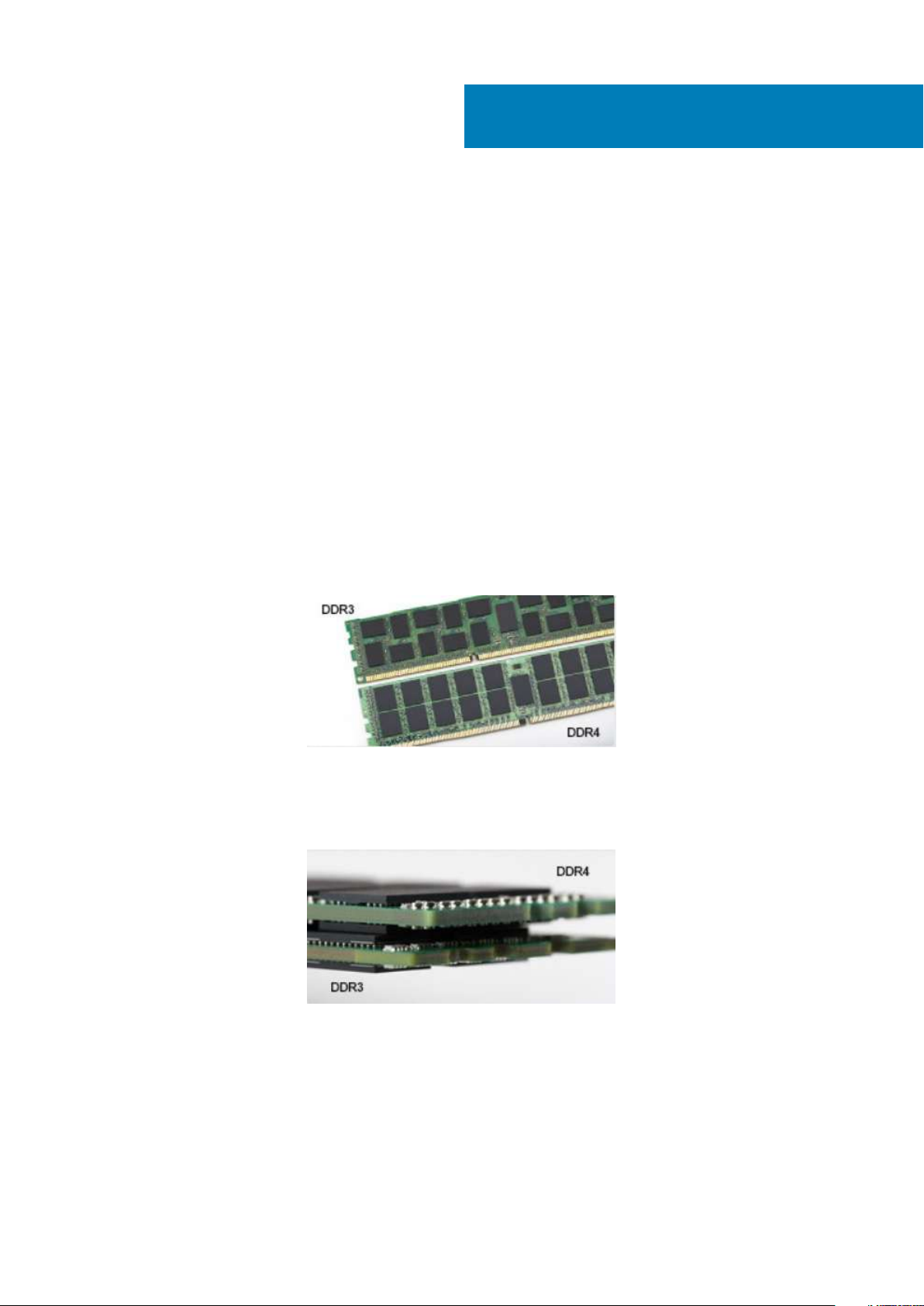
DDR4 Details
There are subtle differences between DDR3 and DDR4 memory modules, as listed below.
Key notch difference
The key notch on a DDR4 module is in a different location from the key notch on a DDR3 module. Both notches are on the insertion edge
but the notch location on the DDR4 is slightly different, to prevent the module from being installed into an incompatible board or platform.
Figure 1. Notch difference
Increased thickness
DDR4 modules are slightly thicker than DDR3, to accommodate more signal layers.
Figure 2. Thickness difference
Curved edge
DDR4 modules feature a curved edge to help with insertion and alleviate stress on the PCB during memory installation.
10 Technology and components
Page 11
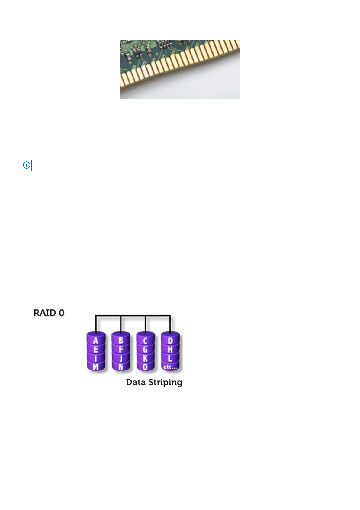
Figure 3. Curved edge
Memory Errors
Memory errors on the system display 2,3 failure code. If all memory fails, the LCD does not turn on. Troubleshoot for possible memory
failure by trying known good memory modules in the memory connectors on the bottom of the system or under the keyboard, as in some
portable systems.
NOTE: The DDR4 memory is imbedded in board and not a replaceable DIMM as shown and referred.
Intel Rapid Storage Technology (Intel RST)
The following article provides an overview of the Intel Rapid Storage Technology application and its features:
Overview
Intel Rapid Storage Technology (IRST) is a hardware, firmware and, software-based RAID solution. IRST was previously known as Matrix
RAID. IRST allows for creation of two RAID volumes on a single RAID array where both the volumes can be of the same or different type.
IRST encapsulates newer level of protection with better performance, and low power consumption. IRST user interface simplifies creation
and management of storage assets.
The fault tolerance is averted using one of the following RAID levels:
1. RAID 0 (Striping):
Multiple storage devices are combined to what appears to be a single virtual drive. Data is arranged as blocks that are spread across
multiple storage devices using process called striping. RAID 0 uses Read/ Write capabilities of two or more storage devices in parallel,
enhancing performance. There is no redundancy, hence if any of the storage devices fails, the RAID has to be re-created.
2. RAID 1 (Mirroring):
Two storage devices are mirrored or duplicated to achieve redundancy and hence enhance reliability in an event of single drive failure.
The performance is that of a single drive.
Technology and components
11
Page 12
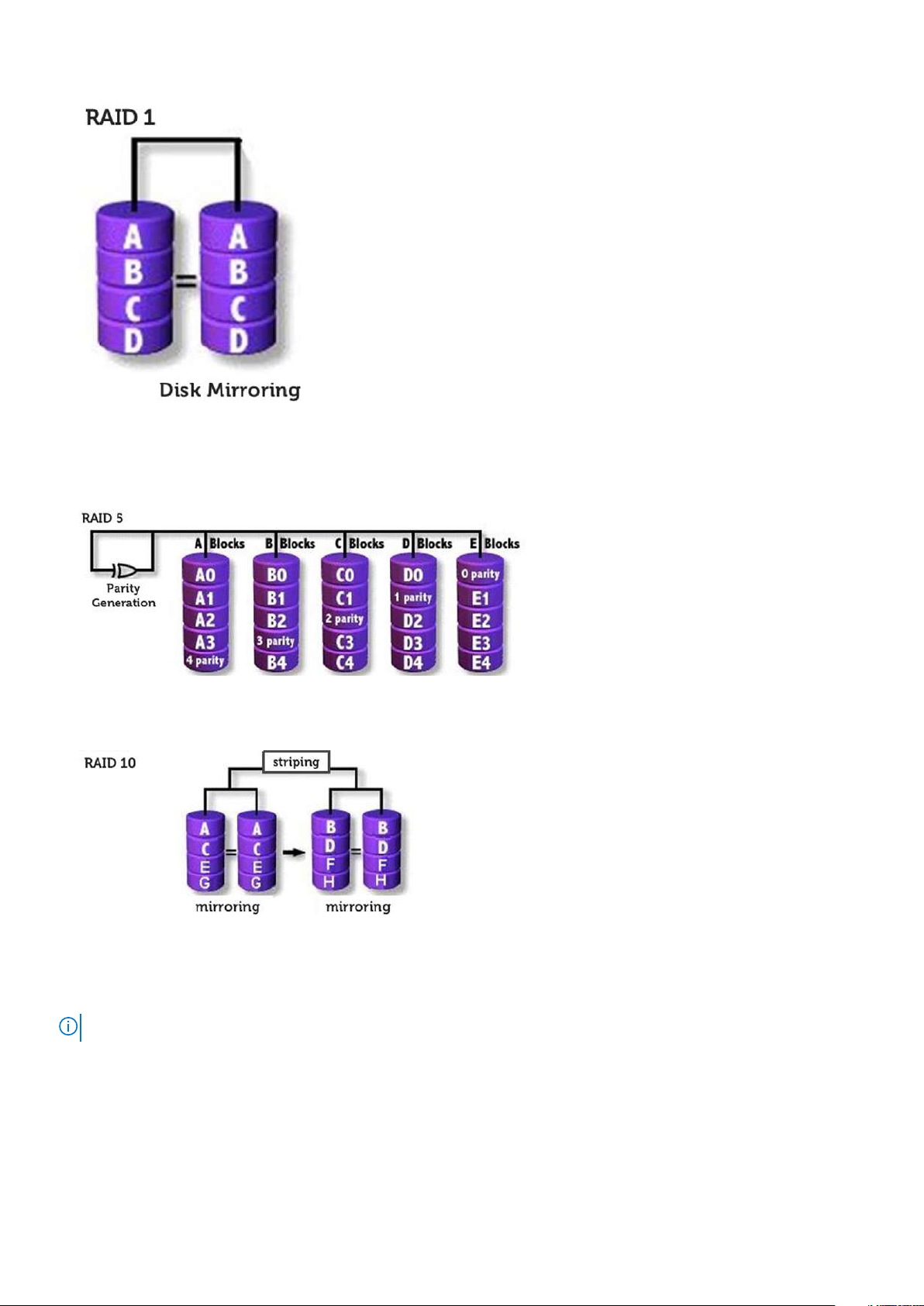
3. RAID 5 (Striping with Parity):
In this RAID level, data is stripped into blocks and spread across three or more storage devices. Each block contains the data and a
parity for fault tolerance. In an event of a drive failure, the parity helps build the lost piece of data. To further enhance the write
performance, IRST uses Volume Write-Back Cache and Coalescer. The Volume Write-Back allows writes to be buffered, and
Coalescer allows multiple write requests to be combined to reduce the overhead on parity calculation.
4. RAID 10 (Striping and Mirroring)):
RAID 10 is created, mirroring (RAID 1) the stripped (RAID 0) array. This RAID level uses four or more storage devices. It has great
reliability like a RAID 1 and performance like a RAID 0.
RAID-ready
A RAID-Ready configuration allows migration from one non-RAID SATA drive to a SATA RAID configuration.
NOTE: A reinstall of the operating system is not required for the migration.
A RAID-Ready system must meet the following requirements:
• Supported Intel Chipsets
• One Serial ATA (SATA) hard drive
• RAID controller enabled in the system setup
• BIOS that includes the IRST option ROM
• IRST software
• Hard drive partition with at least 5 MB of free space
12
Technology and components
Page 13

Features of RAID-enabled systems:
• Intel Rapid Recover Technology - This technology provides full data redundancy by copying data from a designated source drive
(master disk) to a designated destination drive (recovery disk). Data updates of recovery volumes can be continuous or on request.
• Intel Rapid RAID : - This technology allows creation of RAID 0, RAID 1, RAID 5, and RAID 10 volumes on desktop and mobile
platforms. Data is distributed across two or more disks to provide data redundancy or to enhance data storage performance.
• Intel Matrix RAID Technology - This technology allows two independent RAID volumes to be created on a single array. The first
volume occupies part of the array, leaving space for the second volume. The array may consist of two to six SATA disks depending on
the volume types.
• Native command queuing - A feature that allows SATA disks to accept more than one command at a time. With multiple disks that
support NCQ, storage performance is increased on random workloads by allowing the disk to internally optimize the order of
commands.
• Disk capacity greater than 2 TB (Option ROM support) - This feature supports hard disks and solid-state drives with a capacity
greater than 2 TB that are reported as pass-through devices (available) or used in a RAID configuration. Besides booting from a
system disk greater than 2 TB is allowed, if the version of the option ROM in your system supports this feature.
• Password-protected disks - This feature provides high-level security and protection for the data on your disks with a password,
denying access from any unauthorized user.
Advantages of DisplayPort over USB Type-C
• Full DisplayPort audio/video (A/V) performance (up to 4K at 60Hz)
• Reversible plug orientation and cable direction
• Backwards compatibility to VGA, DVI with adaptors
• SuperSpeed USB (USB 3.1) data
• Supports HDMI 2.0a and is backwards compatible with previous versions
HDMI 2.0
This topic explains the HDMI 2.0 and its features along with the advantages.
HDMI (High-Definition Multimedia Interface) is an industry-supported, uncompressed, all-digital audio/video interface. HDMI provides an
interface between any compatible digital audio/video source, such as a DVD player, or A/V receiver and a compatible digital audio and/or
video monitor, such as a digital TV (DTV). The intended applications for HDMI TVs, and DVD players. The primary advantage is cable
reduction and content protection provisions. HDMI supports standard, enhanced, or high-definition video, plus multichannel digital audio
on a single cable.
HDMI 2.0 Features
• HDMI Ethernet Channel - Adds high-speed networking to an HDMI link, allowing users to take full advantage of their IP-enabled
devices without a separate Ethernet cable
• Audio Return Channel - Allows an HDMI-connected TV with a built-in tuner to send audio data "upstream" to a surround audio
system, eliminating the need for a separate audio cable
• 3D - Defines input/output protocols for major 3D video formats, paving the way for true 3D gaming and 3D home theater applications
• Content Type - Real-time signaling of content types between display and source devices, enabling a TV to optimize picture settings
based on content type
• Additional Color Spaces - Adds support for additional color models used in digital photography and computer graphics
• 4K Support - Enables video resolutions far beyond 1080p, supporting next-generation displays that will rival the Digital Cinema
systems used in many commercial movie theaters
• HDMI Micro Connector - A new, smaller connector for phones and other portable devices, supporting video resolutions up to 1080p
• Automotive Connection System - New cables and connectors for automotive video systems, designed to meet the unique
demands of the motoring environment while delivering true HD quality
Advantages of HDMI
• Quality HDMI transfers uncompressed digital audio and video for the highest, crispest image quality.
• Low -cost HDMI provides the quality and functionality of a digital interface while also supporting uncompressed video formats in a
simple, cost-effective manner
• Audio HDMI supports multiple audio formats from standard stereo to multichannel surround sound
Technology and components
13
Page 14

• HDMI combines video and multichannel audio into a single cable, eliminating the cost, complexity, and confusion of multiple cables
currently used in A/V systems
• HDMI supports communication between the video source (such as a DVD player) and the DTV, enabling new functionality
14 Technology and components
Page 15
3
Major components of your system
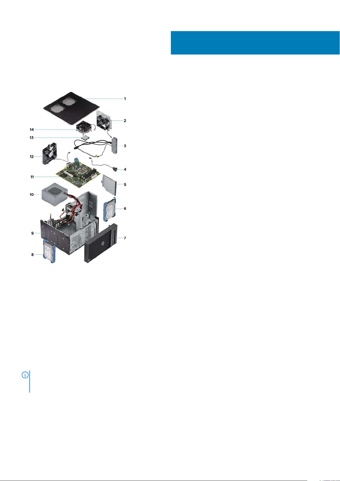
1. Cover
2. System fan
3. IO panel
4. Power button module
5. Optical drive
6. Hard drive
7. Bezel
8. Hard drive
9. Chasis
10. Power supply unit
11. System board
12. Front fan
13. Processor
14. Heatsink assembly
Dell provides a list of components and their part numbers for the original system configuration purchased. These
NOTE:
parts are available according to warranty coverages purchased by the customer. Contact your Dell sales representative
for purchase options.
Major components of your system 15
Page 16
Disassembly and reassembly
Recommended tools
The procedures in this document require the following tools:
• Phillips # 1 screwdriver
• Small flat blade screwdriver
Screw list
The following table provides the list of screws that are used for securing different components to the computer.
4
Table 1. Screw list
Component
Power supply bracket 2
Power supply unit 4
Heat sink blower (95 W heat sink solution) 3
System-fan bracket 1
System board 8
IO panel 1
Security-lock metal bracket 2
Solid-state drive (SSD) card 1
Optical drive bracket 1
Optional IO card 2
WLAN card and SMA antenna module 1
#6-32x1/4'' M2x2.5 M3X3 M2X3.5
Chassis rubber feet
Removing the chassis rubber feet
Steps
1. Follow the procedure in Before Working Inside Your Computer.
16 Disassembly and reassembly
Page 17
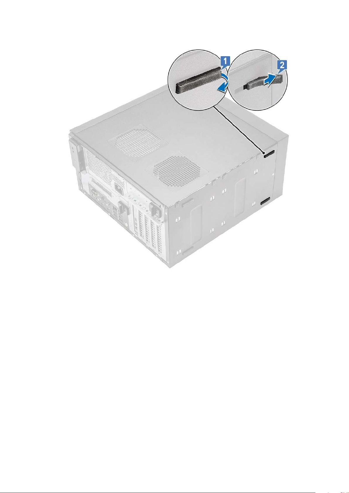
2. Pull one end of rubber feet out of the slot [1] and slide the rubber feet to remove it from the system [2].
Figure 4. Front rubber feet removal
Disassembly and reassembly
17
Page 18
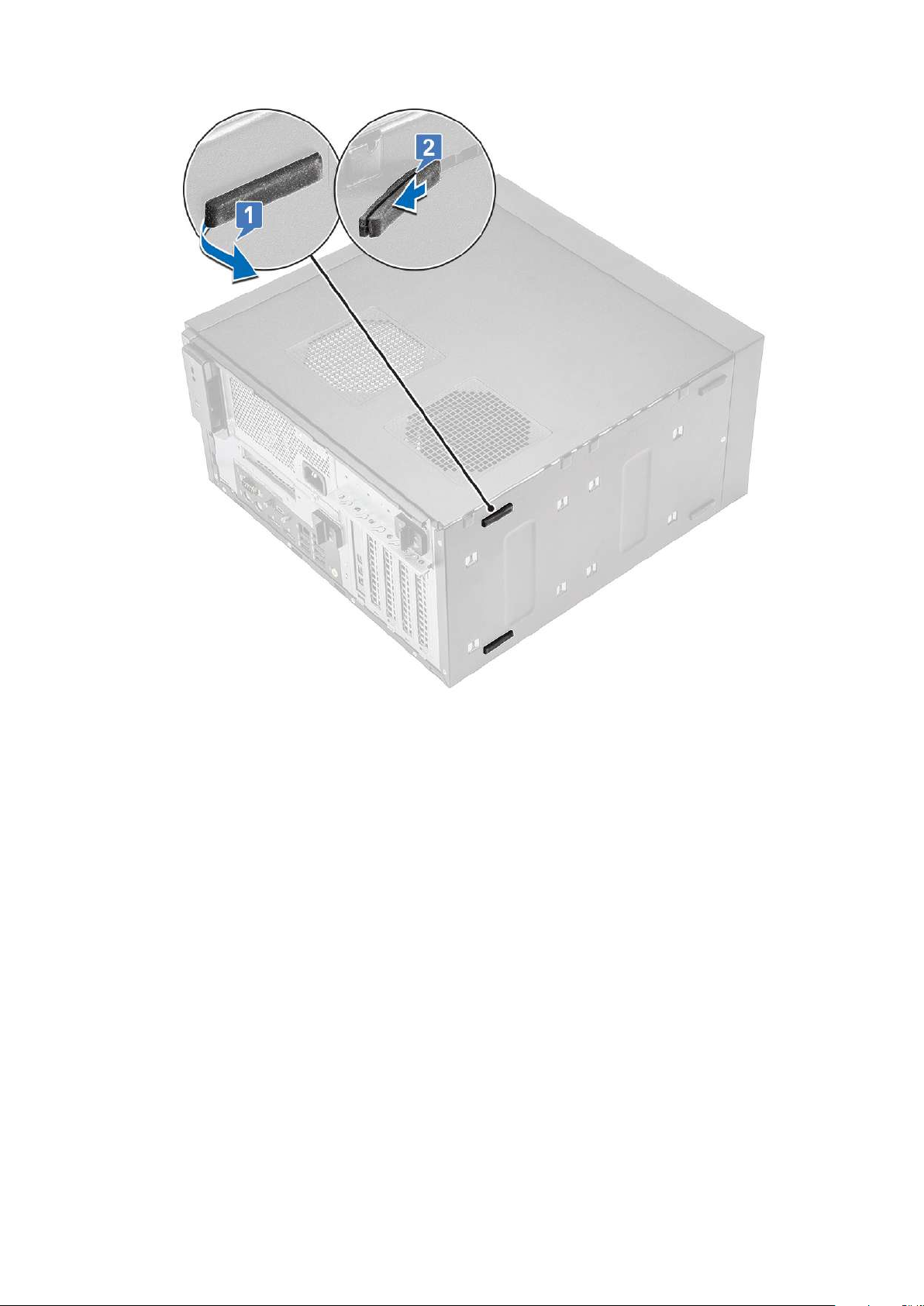
Figure 5. Rear rubber feet removal
Installing the chassis rubber feet
Steps
1. Insert one end of the rubber feet into the slot [1] and slide it to secure it to the system [2] and press the other end to secure it to the
system [3].
18
Disassembly and reassembly
Page 19
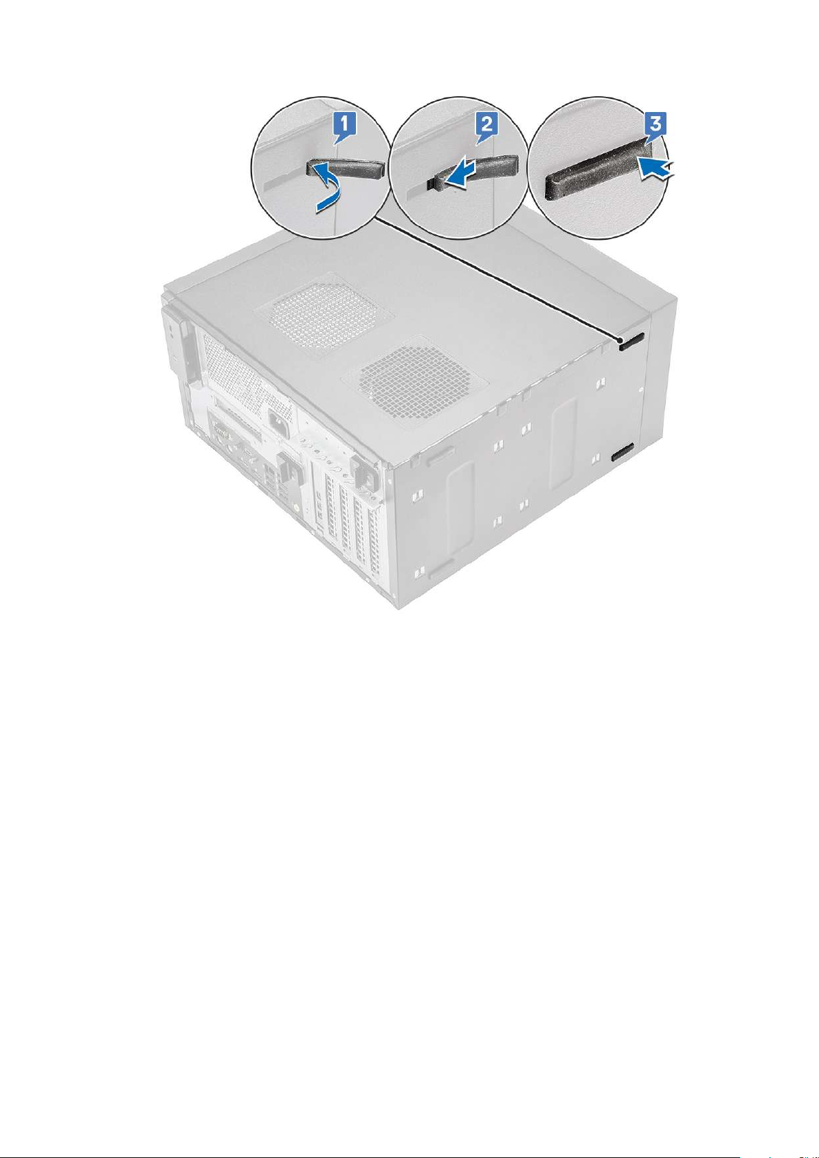
Figure 6. Front rubber feet installation
Disassembly and reassembly
19
Page 20
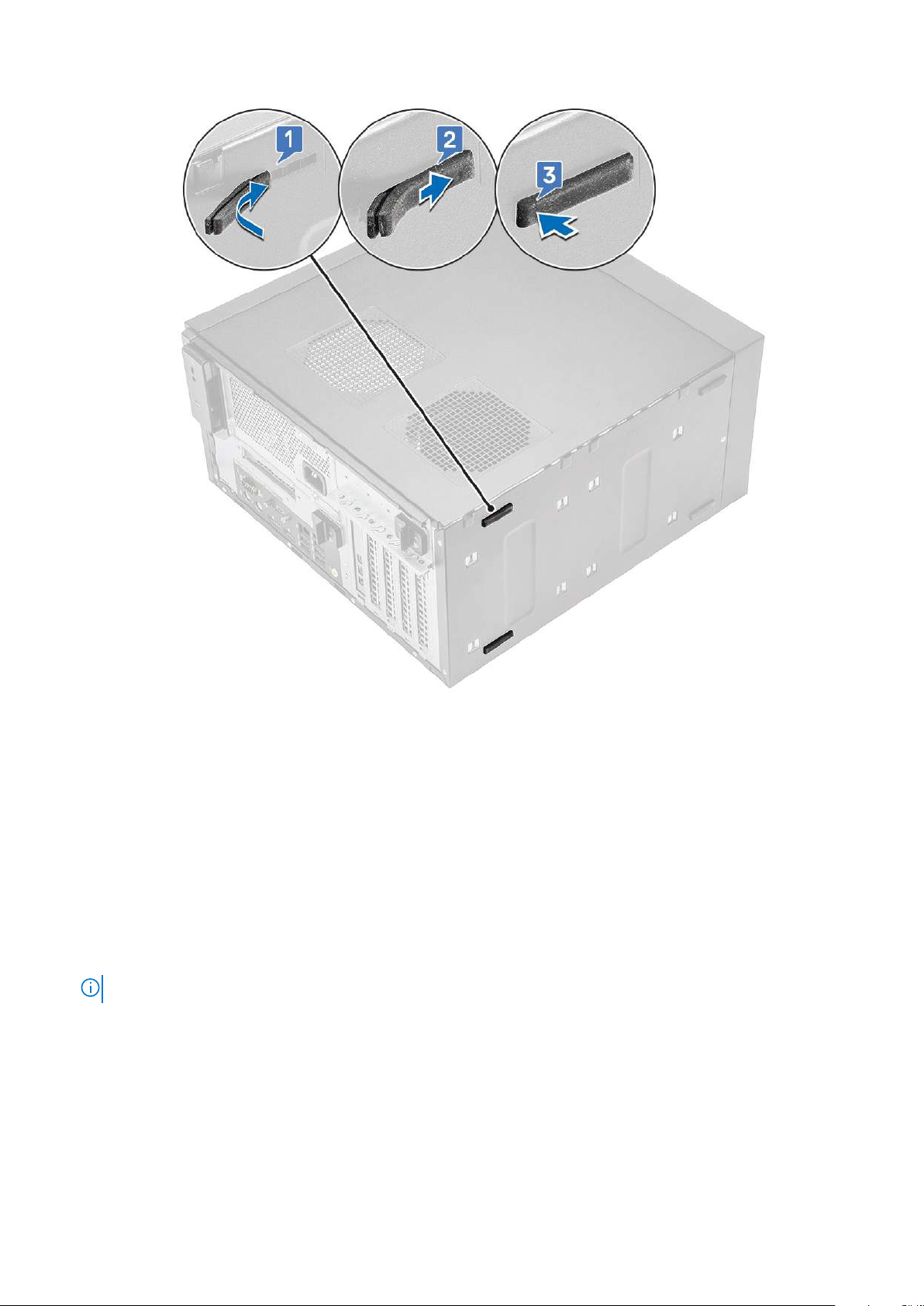
Figure 7. Rear rubber feet installation
2. Follow the procedure in After Working Inside Your Computer.
Cover
Removing the cover
Steps
1. Follow the procedure in Before Working Inside Your Computer.
2. Pull the release latch to release the cover [1].
NOTE: Release latch may have been secured with a security screw. Remove the security screw to release the cover.
20 Disassembly and reassembly
Page 21
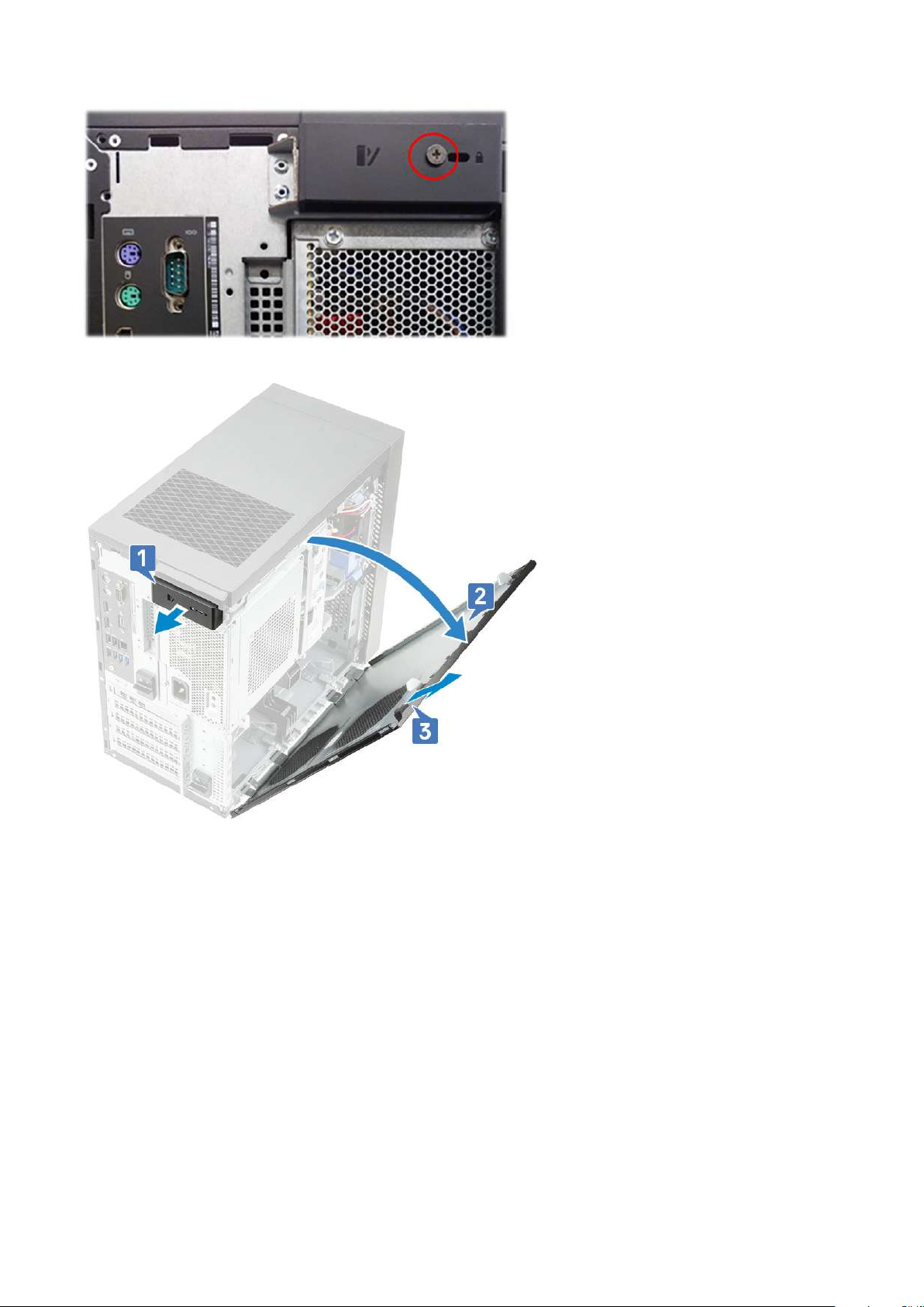
3. Rotate the cover and lift the cover to remove it from the computer [2,3]
Installing the cover
Steps
1. Align the hooks on the cover with the tabs on the chassis of the computer.
2. Rotate the cover until it clicks into place.
Disassembly and reassembly
21
Page 22
3. Follow the procedure in After Working Inside Your Computer.
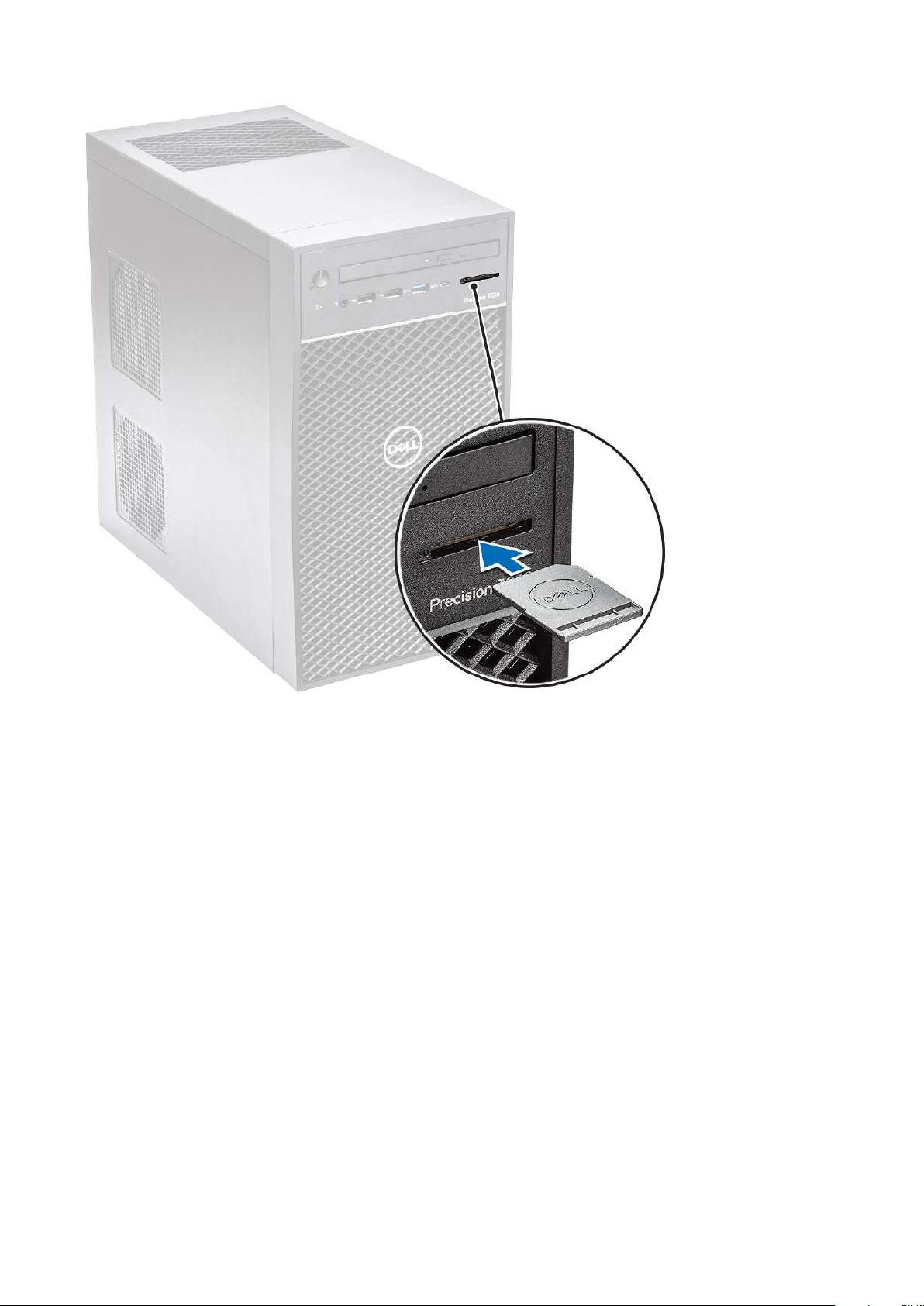
SD card—optional
SD card is an optional component. You will see a SD card only in systems shipped with a WWAN card.
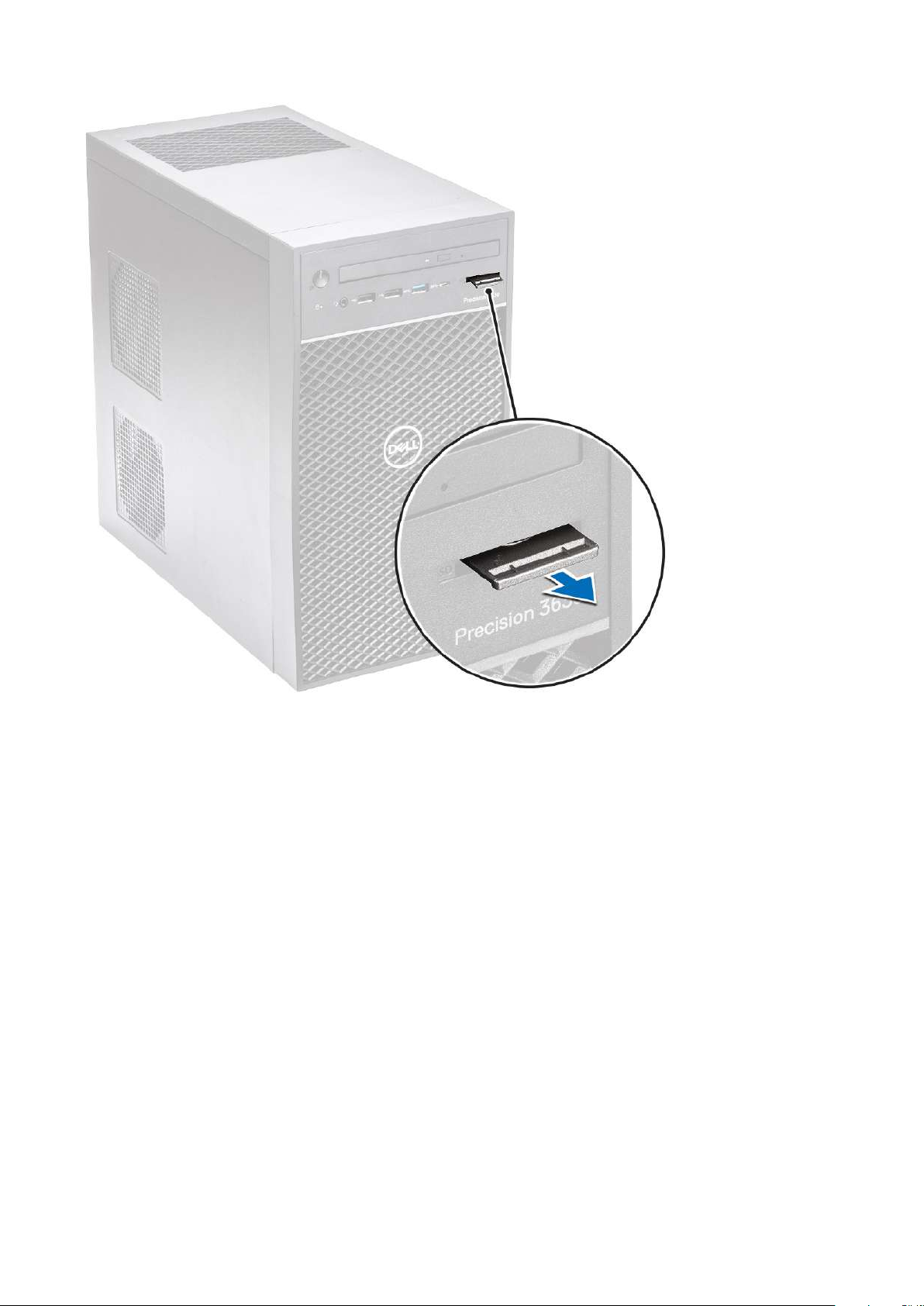
Removing the SD card
Steps
1. Follow the procedure in Before Working Inside Your Computer.
2. Pull the SD card out of the system.
22
Disassembly and reassembly
Page 23
Installing the SD card
Steps
1. Insert the SD card into the SD card slot on the system.
Disassembly and reassembly
23
Page 24
2. Follow the procedure in After Working Inside Your Computer.
Bezel
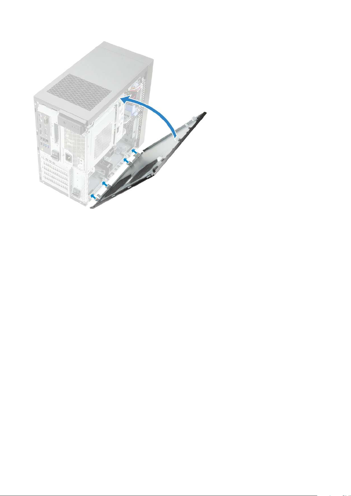
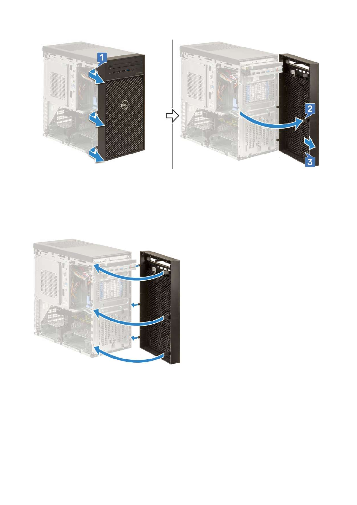
Removing the front bezel
Steps
1. Follow the procedure in Before Working Inside Your Computer.
2. Remove the cover.
3. To remove the front bezel:
a. Lift the retention tabs [1] to release the front bezel.
b. Rotate and pull the front bezel to release the front bezel from the slots on the chassis [2,3].
24
Disassembly and reassembly
Page 25
Installing the front bezel
Steps
1. Hold the bezel and ensure that the hooks on the bezel align with notches on the computer.
2. Rotate the front bezel toward the computer.
3. Press the front bezel until the tabs click into place.
4. Install the cover.
5. Follow the procedure in After Working Inside Your Computer.
Hard drive
Removing the 3.5-inch hard drive
Steps
1. Follow the procedure in Before Working Inside Your Computer.
Disassembly and reassembly
25
Page 26
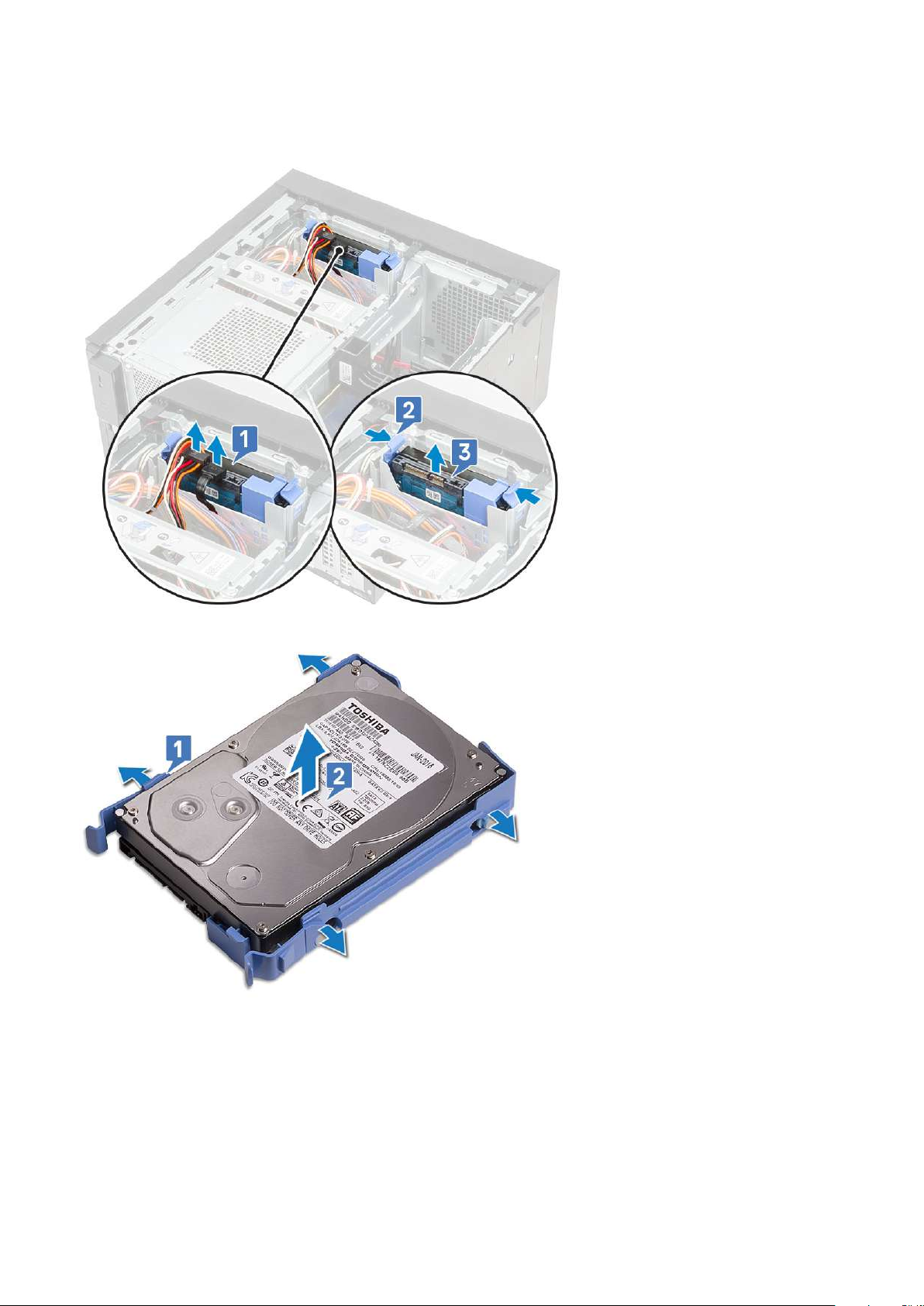
2. Remove the cover.
3. Disconnect the data cable and the power cable from the hard drive [1].
4. Press the blue securing bracket tabs [2] and lift the hard drive bracket out of the hard drive bay [3].
5. Flex the hard drive bracket [1] and lift the hard drive from the hard drive bracket [2].
6. To remove additional hard drive (if available), repeat steps from 3 to 5.
Installing the 3.5-inch hard drive
Steps
1. Insert the holes on one side of the hard disk into the pins on the hard drive bracket and then place the hard drive into the bracket.
26
Disassembly and reassembly
Page 27
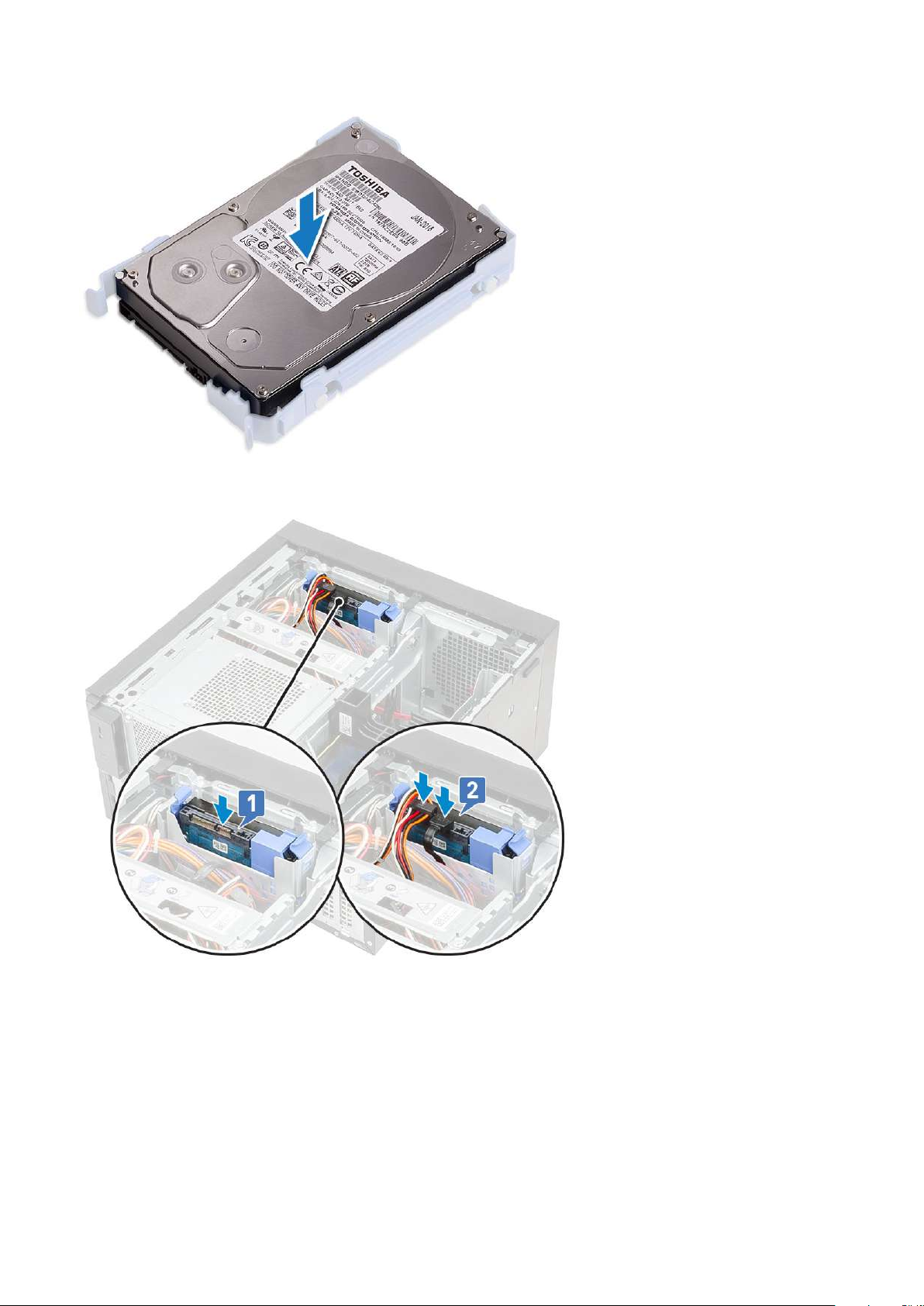
2. Slide the hard drive assembly into the hard drive bay [1].
3. Connect the data cable and the power cable to the hard drive [2].
4. To install additional hard drive, follow the steps from 1 to 3.
5. Install the cover.
6. Follow the procedure in After Working Inside Your Computer.
Removing the 2.5-inch hard drive
Steps
1. Follow the procedure in Before Working Inside Your Computer.
2. Remove the cover.
3. Disconnect the data cables and the power cables from the respective connectors on the hard drives [1].
Disassembly and reassembly
27
Page 28
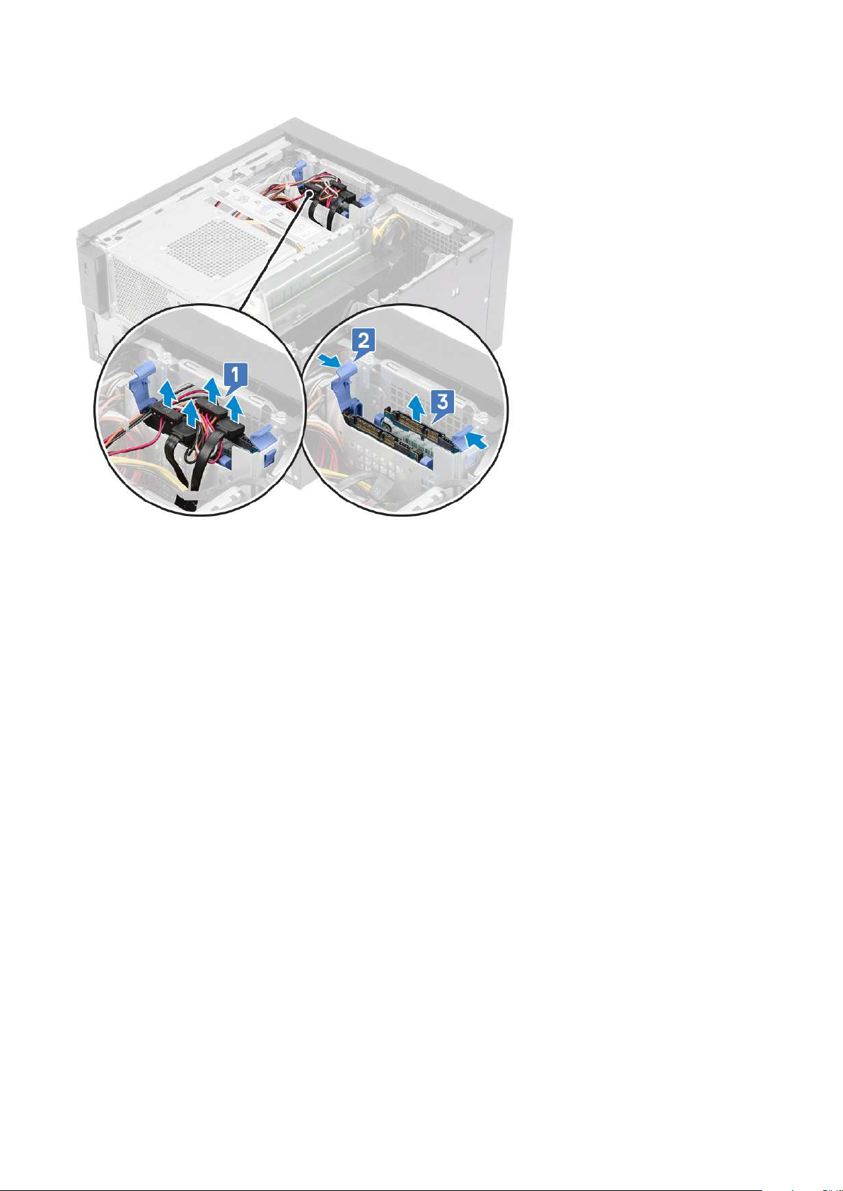
4. Press the blue securing bracket tabs [2] and lift the hard drive bracket out of the front hard drive bay [3].
5. Disconnect the data cables and the power cables from the respective connectors on the hard drives [1].
6. Press the blue securing bracket tabs and lift the hard drive bracket out of the bottom hard drive bays [2].
7. Disconnect the SATA power cable from the connectors on the PSU [3].
28
Disassembly and reassembly
Page 29
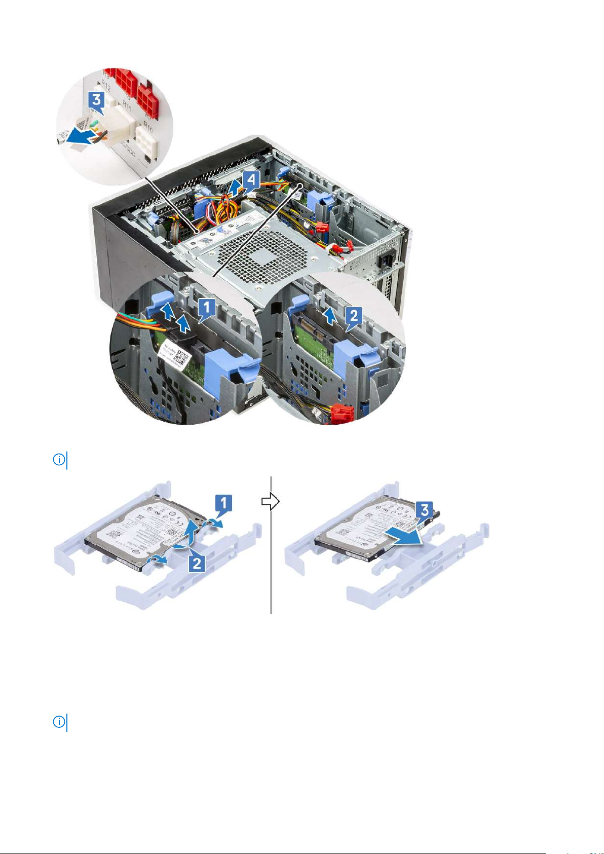
8. Flex the hard drive bracket [1], lift the hard drive [2], and then slide out from the hard drive bracket [3].
NOTE: Follow the same procedure to remove another hard drive on the other side of the bracket.
Installing the 2.5-inch hard drive
Steps
1. Insert the holes on one side of the hard disk into the pins on the hard drive bracket [1], and then place the hard drive into the bracket
such that the pins on other side of the bracket is aligned with the holes on the hard drive [2].
NOTE: Follow the same procedure to install another hard drive on the other side of the bracket.
Disassembly and reassembly 29
Page 30
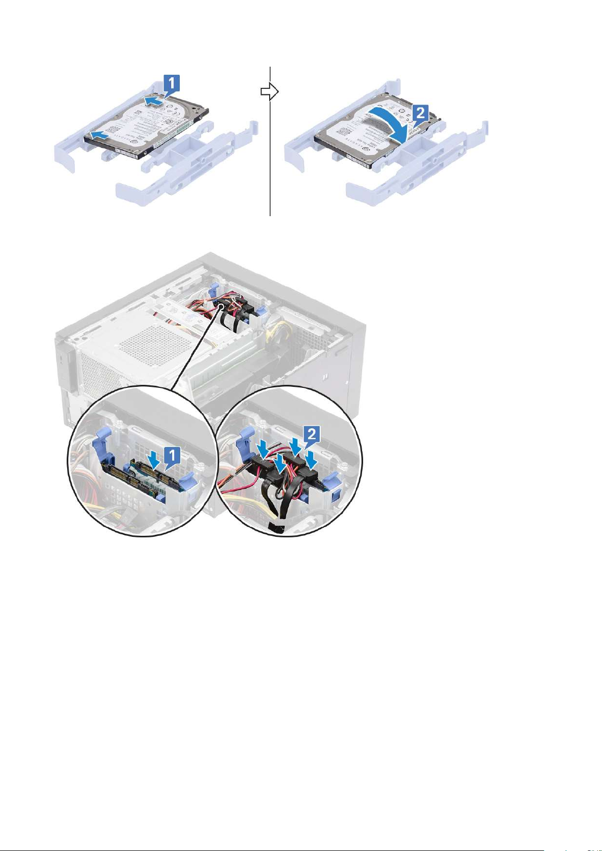
2. Slide the hard drive assembly into the front hard drive bay [1].
3. Connect the data cables and the power cables to the respective connectors on the hard drives [2].
4. Slide the hard drive assembly into the bottom hard drive bay [1].
5. Connect the data cables and the power cables to the respective connectors on the hard drives [2].
6. Route the power SATA cables along the guide to connect to the PSU [3].
30
Disassembly and reassembly
Page 31

7. Install the cover.
8. Follow the procedure in After Working Inside Your Computer.
PSU hinge
Opening the PSU hinge
Steps
1. Follow the procedure in Before working inside your computer.
2. Remove the cover:
3. Unlock the PSU release latches [1,2]
4. Rotate the PSU hinge as shown in the figure [3].
Disassembly and reassembly
31
Page 32

Closing the PSU hinge
Steps
1. Rotate the PSU hinge [1]
2. Unlock the PSU release latches to secure the PSU hinge to the system [2,3].
3. Install the cover:
32
Disassembly and reassembly
Page 33

4. Follow the procedure in After Working Inside Your Computer.
Graphics card
Removing the graphics card
About this task
NOTE: You may see a PCIe card installed in some configurations. Follow the same steps except step 4 to remove the
expansion card.
Steps
1. Follow the procedure in Before working inside your computer.
2. Remove the cover.
3. Disconnect the VGA power cable from the graphics cards in a dual graphics card configuration [1].
4. Lift the plastics latch to free the cables [2] and unroute the cables from the tabs [3].
5. Open the PSU hinge.
6. Press the releasing clip and disconnect the graphics-card power cable from the connector on the graphics card [1].
7.
Lift the side of the PCIe holder that sits on the graphics card [2].
8. Slide the PCIe holder to release the tab on the PCIE holder from the slot on the chassis [3].
A PCIe holder may not be required for system shipped with NVIDIA Quadro P4000 or RTX4000 dual graphics
NOTE:
cards configuration.
Disassembly and reassembly
33
Page 34

9. Push the card retention latch away from the card [1] and lift the graphics card out of the computer [2].
34
Disassembly and reassembly
Page 35

Installing the graphics card
About this task
NOTE: Follow the same steps except step 2 to install the expansion card.
Disassembly and reassembly 35
Page 36

Steps
1. Insert the graphics card to the connector on the system board.
Figure 8. Single graphics card
Figure 9. Dual graphics card
2. Connect the graphics-card power cable to the connector on the graphics card for a single graphics card configuration [1].
36
Disassembly and reassembly
Page 37

3. Insert the tab on the PCIe card holder into the slot on the chassis [2] and press until it is secured to the graphics card [3].
4. Close the PSU hinge.
5. Connect the VGA power cables to the dual graphics card configuration:
a. Unroute the VGA power cables from the securing tabs on the PSU [1].
b. Lift the plastics latch to free the cables [2].
c. Connect the VGA power cables to the connectors on both the graphics card [3].
6. Install the Cover.
7. Follow the procedure in After working inside your computer.
Disassembly and reassembly
37
Page 38

Memory module
Removing the memory module
Steps
1. Follow the procedure in Before Working Inside Your Computer.
2. Remove the Cover.
3. Press the memory module retention tabs on each side of the memory module [1].
4. Lift the memory module out of the connectors on the system board [2].
Installing the memory module
Steps
1. Align the notch on the memory module with the tab on the memory module connector.
2. Press the memory module until the retention tabs clicks into place.
3. Install the cover.
4. Follow the procedure in After Working Inside Your Computer.
38
Disassembly and reassembly
Page 39

Speaker
Removing speaker
Steps
1. Follow the procedure in Before working inside your computer.
2. Remove the:
a. Cover
b. PSU hinge
3. To remove speaker for system shipped with system configuration :
a. Disconnect the speaker cable from the system board [1].
b. Unroute the speaker cable from the tabs on the system board [2,3].
c. Press the release tab and pull the speaker out from front of the system chassis [4].
Installing the speaker
Steps
1. To install speaker for system :
a. Replace the speaker into the rear portion of the chassis above the front fan [1].
b. Route the speaker cable along the tabs on the I/O port of the system board [2,3] and connect it to the system board [4].
Disassembly and reassembly
39
Page 40

2. Close the PSU hinge.
3. Install the Cover.
4. Follow the procedure in After working inside your computer.
Coin cell battery
Removing the coin cell battery
Steps
1. Follow the procedure in Before working inside your computer.
2. Remove the cover.
3. Open the PSU hinge.
4. To remove the coin cell battery:
a. Press the release latch until the coin cell battery pops out [1].
b. Remove the coin cell battery from the connector on the system board [2].
40
Disassembly and reassembly
Page 41

Installing the coin cell battery
Steps
1. Hold the coin cell battery with the "+" sign facing up and slide it under the securing tabs at the positive side of the connector [1].
2. Press the battery into the connector until it locks into place [2].
Disassembly and reassembly
41
Page 42

3. Close the PSU hinge.
4. Install the Cover.
5. Follow the procedure in After working inside your computer.
Power supply unit
Removing the power supply unit
Steps
1. Follow the procedure in Before Working Inside Your Computer.
2. Remove:
a. Cover
b. Heatsink assembly
3. Open the PSU hinge
4. Disconnect the following cables:
• :
a. Disconnect the optical-drive power cable from the optical drive [1].
b. Disconnect the CPU-power cable and system board power cable from the system board [2,3].
c. Disconnect the graphics-card power cable from the connector on the graphics card [4]
d. Unroute the CPU-power cable from the routing guide on the chassis [5].
42
Disassembly and reassembly
Page 43

5. Close the PSU hinge.
6. To remove the power supply unit (PSU):
a. Disconnect the hard-disk power cable [1].
NOTE: There could be up to four hard-disk power cables depending on the quantity of hard-disk drive installed.
b. Remove the two #6-32x1/4'' screws that secure the power-supply bracket to the chassis [2] and lift the power-supply bracket
from the system [3].
c. Remove the four #6-32x1/4'' screws that secure the power-supply unit to the chassis [4].
d. Lift the PSU off the chassis [5].
Disassembly and reassembly
43
Page 44

Installing the power supply unit
Steps
1. Insert the PSU into the PSU slot and slide it towards the back of the computer until it clicks into place [1].
2. Replace the four #6-32x1/4'' screws to secure the PSU to the computer [2].
3. Place the power supply bracket [3] and tighten the two #6-32x1/4'' screws to secure the PSU to the computer [4].
4. Connect the hard drive power cable [5]
44
Disassembly and reassembly
Page 45

5. Open the PSU hinge.
6. Connect the following cables:
• For systems shipped with 95 W CPU system configuration:
a. Route the CPU power cable through the routing guide on the chassis [1].
b. Connect the graphics-card power cable [2].
c. Connect the system-board power cable [3]
d. Connect the CPU power cable to the connector on the system board [4].
e. Connect the optical-drive power cable to the connector on the optical drive [5].
Disassembly and reassembly
45
Page 46

7. Install the:
a. Heatsink assembly
b. Cover
8. Close the PSU hinge.
9. Follow the procedure in After Working Inside Your Computer.
Optical drive
Removing the optical drive
Steps
1. Follow the procedure in Before Working Inside Your Computer.
2. Remove the cover.
3. Front bezel
4. Open the PSU hinge.
5. Disconnect the data cable and the power cable from the optical drive [1].
6. Hold and pull the optical drive latch to unlock the optical drive [2].
46
Disassembly and reassembly
Page 47

7. Slide the optical drive from the front of the computer.
8. Remove the M2x2.5 screw that secures the optical-drive bracket to the optical drive [1] and remove the optical-drive bracket [2].
Disassembly and reassembly
47
Page 48

Installing the optical drive
Steps
1. Align the screw hole on the optical-drive bracket with the screw hole on the optical drive [1] and replace the M2x2.5 screw to secure
the optical-drive bracket to the optical drive [2].
2. Slide the optical drive into the drive bay from the front of the computer until it is secured.
3. Connect the data cable and power cable to the optical drive.
48
Disassembly and reassembly
Page 49

4. Close the PSU hinge.
5. Install the Front bezel
6. Install the cover.
7. Follow the procedure in After Working Inside Your Computer.
WLAN module and SMA antenna
Removing WLAN module and SMA antenna
Steps
1. Follow the procedure in Before Working Inside Your Computer.
2. Remove the:
a. Cover
b. PSU hinge
3. Remove the single M2x3.5 screw that secures the WLAN card to the system board, un-route the antenna cables from the rubber
guides on the system board [1].
4. Slide and remove the external antenna connector from the PCIe slot on the chassis [2].
Disassembly and reassembly
49
Page 50

5. Remove the WLAN card from the system board [3].
6. Remove the plastic bracket from the top of the antenna connector [4].
7. Gentrly remove the antenna cables from the connectors on the WLAN card [5].
8. Separate the WLAN module and SMA antenna [6].
50
Disassembly and reassembly
Page 51

Installing WLAN module and SMA antenna
Steps
1. Assemble the WLAN module with the SMA antenna.
2. Connect the antenna cable to the WLAN module.
3. Replace the plastic bracket on the antenna connectors of the WLAN module.
4. Insert the WLAN module into the M.2 slot on the system board.
5. Replace PCIe bracket into its slot on the chassis.
6. Route the antenna cables through the rubber guides on the system board and replace the single M2x3.5 screw securing the WLAN
module to the system board.
Disassembly and reassembly
51
Page 52

7. Install the:
a. PSU hinge
b. Cover
8. Follow the procedure in After Working Inside Your Computer.
IO panel
Removing the IO panel
Steps
1. Follow the procedure in Before working inside your computer.
2. Remove the:
a. Cover
b. Front bezel
c. Optical drive
3. Open the PSU hinge.
4. Disconnect the IO audio cable from the connector on the system board [1] and unroute the cable from routing guides next to the
system board on the chassis [2].
52
Disassembly and reassembly
Page 53

5. Disconnect the following cables from their respective connectors on the system board:
• System board power connector cable [1,2]
• SD card cable [3]
• Type-C cable [4]
• IO USB cable [5]
• Unroute the cables [6]
Disassembly and reassembly
53
Page 54

6. Remove the #6-32x1/4'' screw that secures the IO panel to the chassis.
54
Disassembly and reassembly
Page 55

7. Lift the IO panel to release the tabs on the IO panel from the slots on the chassis.
Disassembly and reassembly
55
Page 56

8. Pull the IO panel along with the cables to remove it from the IO panel slot on the chassis.
56
Disassembly and reassembly
Page 57

Installing the IO panel
Steps
1. Insert the cables through the IO panel slot on the chassis.
Disassembly and reassembly
57
Page 58

2. Insert the IO-panel tabs into the slots on the system [1] and tilt the IO panel to secure it to the system [2].
58
Disassembly and reassembly
Page 59

3. Replace the #6-32x1/4'' screw to secure the IO panel to the system.
Disassembly and reassembly
59
Page 60

4. Route the cables through the routing channel [1] and connect the following cables to their respective connectors on the system board:
• IO USB cable [2]
• Type-C cable [3]
• SD card cable [4]
• System board power connector cable [5]
60
Disassembly and reassembly
Page 61

5. Route the IO audio cable through the routing clip next to the system board on the chassis [1].
6. Connect the IO audio cable to the connector on the system board [2].
Disassembly and reassembly
61
Page 62

7. Install the:
a. Optical drive
b. Front bezel
c. Cover
8. Close the PSU hinge.
9. Follow the procedure in After Working Inside Your Computer.
Solid state drive
Removing the PCIe SSD card
Prerequisites
NOTE: The instructions are applicable for removal of M.2 SATA SSD card also.
Steps
1. Follow the procedure in Before Working Inside Your Computer.
2. Remove the:
a. cover.
b. Graphics card.
3. Open the PSU hinge.
4. To remove the SSD card:
62
Disassembly and reassembly
Page 63

a. Remove the M2x2.5 screw that secures the PCIe SSD card [1].
b. Slide and lift the PCIe SSD card from the computer [2].
c. Remove the SSD thermal pad [3].
Figure 10. 2242 SSD
Installing the PCIe SSD card
About this task
NOTE: The instructions are applicable for installation of M.2 SATA SSD card also.
Disassembly and reassembly 63
Page 64

Steps
1. Place the SSD thermal pad into the slot on the system board [1] .
2. Slide the PCIe SSD card into the slot and tighten the M2x2.5 screw to secure the SSD card to the system board [2,3].
Figure 11. 2242 SSD
3. Install the:
a. Cover.
b. Graphics card.
4. Close the PSU hinge.
5. Follow the procedure in After Working Inside Your Computer.
64
Disassembly and reassembly
Page 65

Power button module
Removing power button module
About this task
Steps
1. Follow the procedure in Before working inside your computer.
2. Remove the:
a. Cover
b. Front bezel
c. IO panel
3. Open the PSU hinge.
4. Disconnect the power button module cable from the connector on the system board [1].
5. Remove the button module cable from the routing guides next to the system board on the chassis [2,3].
6. Remove the adhesive tape that secures the power button module to the chassis [1].
7. Press the notches to release the power button module and pull the power button module to remove it from the system [2,3].
Disassembly and reassembly
65
Page 66

Installing power button module
About this task
Steps
1. Insert the power button module into its slot on the system [1] and press the notches and secure it to the system [2].
2. Affix the adhesive tape to secure the power button module to the system [3].
66
Disassembly and reassembly
Page 67

3. Route the power button module cable through the routing clips on the system [1,2].
4. Connect the power button module cable to the connector on the system board [3].
Disassembly and reassembly
67
Page 68

5. Install the:
a. IO panel
b. Optical drive
c. Front bezel
d. Cover
6. Close the PSU hinge.
7. Follow the procedure in After Working Inside Your Computer.
Heatsink assembly
Removing heatsink assembly - 65 W or 80 W CPU
About this task
These steps applies to system configurations shipped with 65 W or 80 W CPU.
Steps
1. Follow the procedure in Before working inside your computer.
2. Remove the Cover.
3. Open the PSU hinge.
4. To remove the heat sink assembly:
a. Disconnect the heat sink assembly cable from the connector on the system board [1].
b. Loosen the 4 captive screws that secure the heat sink assembly [2] and lift it from the system [3].
68
Disassembly and reassembly
Page 69

NOTE: Loosen the screws in a sequential order (1,2,3,4) as mentioned on the system board.
Removing blower and heat sink assembly — 125 W CPU
About this task
These steps applies to system configurations shipped with 125 W CPU.
Steps
1. Follow the procedure in Before working inside your computer.
2. Remove the cover.
3. Open the PSU hinge.
4. Remove the three #6-32x1/4'' screws that secure the blower to the heat-sink assembly [1].
5. Flip over the blower and place it to a side [2].
Disassembly and reassembly
69
Page 70

6. Loosen the captive screws that secure the heat-sink assembly to the system board [1].
7. Lift the heat-sink assembly off the system board [2].
8. Disconnect the blower cable from the system board.
70
Disassembly and reassembly
Page 71

Installing heatsink assembly - 65 W or 80 W CPU
About this task
These steps applies to system configurations shipped with 65 W or 80 W CPU.
Steps
1. Align the heat sink assembly with the screw holders on the system board and place it on the processor [1].
2. Tighten the 4 captive screws to secure the heat sink assembly to the system board [2].
NOTE: Tighten the screws in a sequential order (1,2,3,4) as mentioned on the system board.
3. Connect the heat sink assembly cable to the connector on the system board [3].
Disassembly and reassembly
71
Page 72

4. Close the PSU hinge.
5. Install the cover.
6. Follow the procedure in After working inside your computer.
Installing blower and heat sink assembly — 125 W CPU
About this task
These steps applies to system configurations shipped with 125 W CPU.
Steps
1. Route the blower cable through the heat sink assembly [1] and connect the blower cable to the connector on the system board [2].
72
Disassembly and reassembly
Page 73

2. Place the heat-sink assembly over the processor.
3. Align the captive screws on the heat-sink assembly with the screw holes on the system board.
4. Tighten the captive screws that secure the heat-sink assembly to the system board.
5. Align the screw holes on the blower to the screw holes on the heat-sink assembly and place the blower over the heat-sink assembly
[1].
6. Replace the screws that secure the blower to the heat-sink assembly [2].
Disassembly and reassembly
73
Page 74

7. Close the PSU hinge.
8. Install the cover.
9. Follow the procedure in After working inside your computer.
VR heat sink
Removing VR heatsink
Steps
1. Follow the procedure in Before working inside your computer.
2. Remove the:
a. Cover
b. Graphics card
c. SSD
d. Heatsink assembly
3. Open the PSU hinge.
4. Loosen the captive screws that secure the VR heatsink to the system board [1].
5. Lift the VR heatsink from the system board [2].
74
Disassembly and reassembly
Page 75

Figure 12. VR heatsink assembly for systems shipped with 65 W or 80 W CPU
Figure 13. VR heatsink assembly for systems shipped with 125 W CPU
Installing VR heatsink
Steps
1. Align the screws on the heatsink with the screw holders on the system board and place the VR heatsink on the system board [1].
Disassembly and reassembly
75
Page 76

2. Tighten the captive screws that secure the VR heatsink to the system board [2].
Figure 14. VR heatsink assembly for systems shipped with 65 W or 80 W CPU
Figure 15. VR heatsink assembly for systems shipped with 125 W CPU
3. Install the:
a. Heatsink assembly
b. SSD
c. Graphics card
d. Cover
76
Disassembly and reassembly
Page 77

4. Close the PSU hinge
5. Follow the procedure in After working inside your computer.
Front fan
Removing front fan
Steps
1. Follow the procedure in Before Working Inside Your Computer.
2. Remove the:
a. Cover
b. PSU hinge
3. Unroute the hard drive card cables from over the fan bracket.
4. Disconnect the front fan cable from the system board.
5. To release the front fan from the bracket, push the tab securing the front fan to the bracket.
Disassembly and reassembly
77
Page 78

6. Lift the front fan off the computer.
7. Release the fan cable from the hook on the fan frame [1] and flip over [2].
8. Pry from all sides [3] and remove the fan from the frame [4].
78
Disassembly and reassembly
Page 79

Installing front fan
Steps
1. Replace the fan into the frame [1] and flip over [2].
2. Route the fan cable through the hook on the fan frame [3].
3. Replace the front fan on the fan bracket.
4. Press the tab to secure the front fan to the bracket on the computer.
Disassembly and reassembly
79
Page 80

5. Connect the front fan cable to the system board.
6. Route the hard drive card cables from over the front fan bracket.
80
Disassembly and reassembly
Page 81

System fan
Removing system fan
Steps
1. Follow the procedure in Before Working Inside Your Computer.
2. Remove the:
a. Cover
b. PSU hinge
c. Heatsink assembly
3. Disconnect the system fan cable from the connector on the system board.
4. Remove the #6-32x1/4'' screw that secures the system-fan bracket to the chassis [1].
5. Slide the system-fan assembly towards the front of the computer to release it from the chassis and pull the system-fan assembly to
remove it from the system [3].
Disassembly and reassembly
81
Page 82

6. Unroute the system fan cable from the routing channel on the system-fan bracket [1].
7. To release the system fan from the bracket, pull the rubber grommets and remove the grommets securing the system fan to the
bracket [2].
8. Lift the system fan off the system-fan bracket [3].
Figure 16. Removing the chassis fan
Installing system fan
Steps
1. Insert the rubber grommets through the holders on the system-fan bracket, align the system fan holes with the rubber grommets and
insert the rubber grommets through the holes on the system fan to secure the system fan to the bracket [1].
2. Route the system fan cable through the routing channel on the system-fan bracket [2].
82
Disassembly and reassembly
Page 83

3. Align the grooves on the system-fan assembly with the holders on the chassis and slide the assembly [1].
4. Replace the #6-32x1/4'' screw to secure the system-fan bracket to the chassis [2].
5. Connect the system fan cable to the connector on the system board [3].
6. Install the:
a. Heatsink assembly
b. PSU hinge
c. Cover
7. Follow the procedure in After working inside your computer.
Disassembly and reassembly
83
Page 84

Optional IO card
Removing optional IO card
About this task
NOTE: You may see one of these cards-HDMI/DisplayPort/VGA/Type-C based on the additional component you may
have ordered with the system.
Steps
1. Follow the procedure in Before working inside your computer.
2. Remove the cover.
3. Open the PSU hinge.
4. To remove the optional IO card:
a. Disconnect the IO card cable from the connector on the system board [1].
b. Remove the two M3X3 screws that secure the IO card to the system [2].
c. Remove the IO card from the system [3].
Installing the optional IO card
Steps
1. To remove the metal bracket as shown below, insert a flathead screwdriver in the hole of the bracket [1], push the bracket to release
the bracket [2], and then lift the bracket out from the system.
84
Disassembly and reassembly
Page 85

2. Insert the IO card into its slot from the inside of your computer [1] and replace the two M3X3 screws to secure the IO card to the
system [2].
3. Connect the IO card cable to the connector on the system board [3].
4. Close the PSU hinge.
5. Install the cover.
Disassembly and reassembly
85
Page 86

Processor
Removing the processor
Steps
1. Follow the procedure in Before Working Inside Your Computer.
2. Remove the:
a. Cover
b. PSU hinge
c. Heatsink assembly
3. To remove the processor:
a. Release the socket lever by pushing the lever down and out from under the tab on the processor shield [1].
b. Lift the lever upward and lift the processor shield [2].
c. Lift the processor out of the socket [3].
Installing the processor
Steps
1. Align the pin-1 indicator of the processor with the triangle on the socket and place the processor on the socket such that the slots on
the processor align with the socket keys [1].
2. Close the processor shield by sliding it under the retention screw [2].
3. Lower the socket lever and push it under the tab to lock it [3].
86
Disassembly and reassembly
Page 87

4. Install the:
a. Heatsink assembly
b. PSU hinge
c. Cover
5. Follow the procedure in After Working Inside Your Computer.
Intrusion switch
Removing intrusion switch
Steps
1. Follow the procedure in Before working inside your computer.
2. Remove the cover.
3. Open the PSU hinge.
4. To remove the intrusion switch:
a. Disconnect the intrusion switch cable from the connector on the system board [1].
b. Unroute the intrusion switch cable from the routing clips on the chassis [2].
c. Slide the intrusion switch and lift it to remove from the computer [3].
Disassembly and reassembly
87
Page 88

Installing intrusion switch
Steps
1. Slide the intrusion switch into the slot on the computer [1].
2. Route the intrusion switch cable through the routing clips on the chassis [2].
3. Connect the intrusion switch cable to the connector on the system board [3].
88
Disassembly and reassembly
Page 89

4. Close the PSU hinge.
5. Install the cover.
6. Follow the procedure in After working inside your computer.
System board
Removing the system board
Steps
1. Follow the procedure in Before Working Inside Your Computer.
2. Remove the:
a. Cover
b. PSU hinge
c. Memory module
d. Graphics card
e. SSD
f. WLAN module and SMA antenna
g. Heatsink assembly
h. VR heat sink (for models shipped with 95W heat sink assembly)
i. Processor
3. Remove the following cables:
• System fan cable, intrusion cable, and IO panel cable [1]
• CPU power cable [2]
• System board power connector cable [3]
4. Remove the following cables:
• SD card cable [1]
• Type-C cable [2]
• IO USB cable [3]
Disassembly and reassembly
89
Page 90

• Primary HDD SATA cable [4]
• ODD SATA cable [5]
5. Remove the following cables:
• Speaker cable [1]
• IO audio cable [2]
6. Remove the 8 #6-32x1/4'' screws that secure the system board to the chassis.
90
Disassembly and reassembly
Page 91

7. Lift the system board at an angle and remove it from the computer.
Installing the system board
Steps
1. Slide the I/O ports on the system board into the slots on the chassis and place the system board on the chassis [1]. Align the screw
holes on the system board with the screw holes on the chassis [2].
Disassembly and reassembly
91
Page 92

2. Replace the 8 #6-32x1/4'' screws that secure the system board to the chassis.
3. Route and connect the following cables:
• IO audio cable [1]
• Speaker cable [2]
92
Disassembly and reassembly
Page 93

4. Route and connect the following cables:
• ODD SATA cable [1]
• Primary HDD SATA cable [4]
• IO USB cable [3]
• Type-C cable [4]
• SD card cable [5]
5. Route and connect the following cables:
• System board power connector cable [1]
Disassembly and reassembly
93
Page 94

• CPU power cable [2]
• System fan cable, intrusion cable, and IO panel cable [3]
6. Install the:
a. Processor
b. VR heat sink (for models shipped with 95W heat sink assembly)
c. Heatsink assembly (for models shipped with 95W heat sink assembly)
d. WLAN module and SMA antenna (for models shipped with 95W heat sink assembly)
e. SSD
f. Graphics card
g. Memory module
h. PSU hinge
i. Cover
7. Follow the procedure in After Working Inside Your Computer.
94
Disassembly and reassembly
Page 95

System board layout
This topic illustrates the system board layout and calls out the ports and connectors on the system board.
1. Optional I/O card connector
2. ATX PSU power connector : ATX CPU
3. CPU socket
4. Coin-cell battery
5. Memory module connector
6. Top-fan connector
7. Intrusion switch connector
8. Power button module connector: PWR SW
9. ATX PSU power connector : ATX SYS
10. SD Card reader connector
11. Front panel USB Type-C connector
12. Front panel USB Type-A connector
13. SATA 3.0 data connector : SATA0
14. SATA 3.0 data connector : SATA1
15. SATA 3.0 data connector : SATA2 and 3
16. M.2 2280 PCIe x4, keyed M for solid-state drive
17. Front fan connector
18. CAC_PIV/BT connector
19. M.2 2280 PCIe x4/SATA, keyed M for solid-state drive
20. PWR_BTN
21. System fan connector: HDD FAN
22. Front panel audio connector
23. Internal Speaker
24. Full Height PCIe x4 slot (open-ended)
25. PCI-32 slot
26. Full Height PCIe x16 slot
27. CPU Fan connector
Disassembly and reassembly
95
Page 96

28. M.2 2230 PCIe x1 slot, keyed E for WiFi and Bluetooth card
96 Disassembly and reassembly
Page 97

5
Troubleshooting
Real-Time Clock (RTC Reset)
The Real Time Clock (RTC) reset function allows you or the service technician to recover Dell Inspiron, systems from No POST/No
Power/No Boot situations. The legacy jumper enabled RTC reset has been retired on these models.
Start the RTC reset with the system powered off and connected to AC power. Press and hold the power button for thirty (30) seconds.
The system RTC Reset occurs after you release the power button.
System diagnostic lights
Power-supply diagnostics light
Indicates the status of the power-supply in either of the two sates:
• Off: No Power
• On: Power is supplied.
Power button light
Table 2. Power button LED status
Power button LED state System state Description
Off
Solid White S0 Working state
Solid Amber Various sleep states or No POST
Blinking Amber/White Failure to POST
This platform relies on the Power button LED light blinking in an amber/white pattern to determine a failure as listed in the following table:
NOTE:
The blinking patterns consists of two numbers (representing First Group: Amber blinks, Second Group: White blinks).
• First Group: The Power button LED light blinks Amber, 1 to 9 times followed by a short pause with LED off for a
couple of seconds.
• Second Group: The Power button LED light then blinks White, 1 to 9 times, followed by a longer pause before the
next cycle starts again after a short interval.
.
Example: No Memory detected (2,3). Power button LED blinks 2-times in Amber followed by a pause, and then blinks 3-times in White.
The Power button LED will pause for few seconds before the next cycle repeats itself again.
Table 3. Diagnostics LED codes
• S4
• S5
There is in Hibernate or Off state.
Diagnostic light codes Problem description
1,2 Unrecoverable SPI flash failure
2,1 CPU failure
2,2 System board failure, corrupt BIOS, ROM error
2,3 No memory/RAM detected
Troubleshooting 97
Page 98

Table 3. Diagnostics LED codes(continued)
Diagnostic light codes Problem description
2,4 Memory/RAM failure
2,5 Invalid Memory installed
2,6 System board error, chipset error, clock failure, gate A20 failure, super I/O failure,
keyboard controller failure
3,1 CMOS battery failure
3,2 PCIe or video card/chip failure
3,3 Recovery Image not found
3,4 Recovery Image found but invalid
3,5 Power Rail Failure
3,6 Paid SPI volume error
3,7 Intel (ME) Management Engine error
4,2 CPU power cable connection issue
Diagnostic error messages
Table 4. Diagnostic error messages
Error messages Description
AUXILIARY DEVICE FAILURE
BAD COMMAND OR FILE NAME
CACHE DISABLED DUE TO FAILURE
CD DRIVE CONTROLLER FAILURE
DATA ERROR
DECREASING AVAILABLE MEMORY
DISK C: FAILED INITIALIZATION
DRIVE NOT READY
ERROR READING PCMCIA CARD
The touchpad or external mouse may be faulty. For an external
mouse, check the cable connection. Enable the Pointing Device
option in the System Setup program.
Ensure that you have spelled the command correctly, put spaces in
the proper place, and used the correct path name.
The primary cache internal to the microprocessor has failed.
Contact Dell
The optical drive does not respond to commands from the
computer.
The hard drive cannot read the data.
One or more memory modules may be faulty or improperly seated.
Reinstall the memory modules or, if necessary, replace them.
The hard drive failed initialization. Run the hard drive tests in Dell
Diagnostics.
The operation requires a hard drive in the bay before it can
continue. Install a hard drive in the hard drive bay.
The computer cannot identify the ExpressCard. Reinsert the card
or try another card.
EXTENDED MEMORY SIZE HAS CHANGED
THE FILE BEING COPIED IS TOO LARGE FOR THE
DESTINATION DRIVE
A FILENAME CANNOT CONTAIN ANY OF THE FOLLOWING
CHARACTERS: \ / : * ? " < > | -
98 Troubleshooting
The amount of memory recorded in non-volatile memory (NVRAM)
does not match the memory module installed in the computer.
Restart the computer. If the error appears again, Contact Dell
The file that you are trying to copy is too large to fit on the disk, or
the disk is full. Try copying the file to a different disk or use a larger
capacity disk.
Do not use these characters in filenames.
Page 99

Table 4. Diagnostic error messages(continued)
Error messages Description
GATE A20 FAILURE
A memory module may be loose. Reinstall the memory module or, if
necessary, replace it.
GENERAL FAILURE
HARD-DISK DRIVE CONFIGURATION ERROR
HARD-DISK DRIVE CONTROLLER FAILURE 0
HARD-DISK DRIVE FAILURE
HARD-DISK DRIVE READ FAILURE
The operating system is unable to carry out the command. The
message is usually followed by specific information. For example,
Printer out of paper. Take the appropriate
action.
The computer cannot identify the drive type. Shut down the
computer, remove the hard drive, and boot the computer from an
optical drive. Then, shut down the computer, reinstall the hard
drive, and restart the computer. Run the Hard Disk Drive tests in
Dell Diagnostics.
The hard drive does not respond to commands from the computer.
Shut down the computer, remove the hard drive, and boot the
computer from an optical drive. Then, shut down the computer,
reinstall the hard drive, and restart the computer. If the problem
persists, try another drive. Run the Hard Disk Drive tests in Dell
Diagnostics.
The hard drive may be defective. Shut down the computer,
remove the hard drive, and boot the computer from an optical.
Then, shut down the computer, reinstall the hard drive, and restart
the computer. If the problem persists, try another drive. Run the
Hard Disk Drive tests in Dell Diagnostics.
INSERT BOOTABLE MEDIA
INVALID CONFIGURATION INFORMATION-PLEASE RUN
SYSTEM SETUP PROGRAM
KEYBOARD CLOCK LINE FAILURE
KEYBOARD CONTROLLER FAILURE
KEYBOARD DATA LINE FAILURE
KEYBOARD STUCK KEY FAILURE
LICENSED CONTENT IS NOT ACCESSIBLE IN
MEDIADIRECT
MEMORY ADDRESS LINE FAILURE AT ADDRESS, READ
VALUE EXPECTING VALUE
The operating system is trying to boot to non-bootable media,
such as an optical drive. Insert bootable media.
The system configuration information does not match the
hardware configuration. The message is most likely to occur after a
memory module is installed. Correct the appropriate options in the
system setup program.
For external keyboards, check the cable connection. Run the
Keyboard Controller test in Dell Diagnostics.
For external keyboards, check the cable connection. Restart the
computer, and avoid touching the keyboard or the mouse during
the boot routine. Run the Keyboard Controller test in Dell
Diagnostics.
For external keyboards, check the cable connection. Run the
Keyboard Controller test in Dell Diagnostics.
For external keyboards or keypads, check the cable connection.
Restart the computer, and avoid touching the keyboard or keys
during the boot routine. Run the Stuck Key test in Dell
Diagnostics.
Dell MediaDirect cannot verify the Digital Rights Management
(DRM) restrictions on the file, so the file cannot be played.
A memory module may be faulty or improperly seated. Reinstall the
memory module or, if necessary, replace it.
Troubleshooting 99
Page 100

Table 4. Diagnostic error messages(continued)
Error messages Description
MEMORY ALLOCATION ERROR
The software you are attempting to run is conflicting with the
operating system, another program, or a utility. Shut down the
computer, wait for 30 seconds, and then restart it. Run the
program again. If the error message still appears, see the software
documentation.
MEMORY DOUBLE WORD LOGIC FAILURE AT ADDRESS,
READ VALUE EXPECTING VALUE
MEMORY ODD/EVEN LOGIC FAILURE AT ADDRESS, READ
VALUE EXPECTING VALUE
MEMORY WRITE/READ FAILURE AT ADDRESS, READ
VALUE EXPECTING VALUE
NO BOOT DEVICE AVAILABLE
NO BOOT SECTOR ON HARD DRIVE
NO TIMER TICK INTERRUPT
NOT ENOUGH MEMORY OR RESOURCES. EXIT SOME
PROGRAMS AND TRY AGAIN
OPERATING SYSTEM NOT FOUND
OPTIONAL ROM BAD CHECKSUM
SECTOR NOT FOUND
A memory module may be faulty or improperly seated. Reinstall the
memory module or, if necessary, replace it.
A memory module may be faulty or improperly seated. Reinstall the
memory module or, if necessary, replace it.
A memory module may be faulty or improperly seated. Reinstall the
memory module or, if necessary, replace it.
The computer cannot find the hard drive. If the hard drive is your
boot device, ensure that the drive is installed, properly seated, and
partitioned as a boot device.
The operating system may be corrupted, Contact Dell.
A chip on the system board may be malfunctioning. Run the
System Set tests in Dell Diagnostics.
You have too many programs open. Close all windows and open
the program that you want to use.
Reinstall the operating system. If the problem persists, Contact
Dell.
The optional ROM has failed. Contact Dell.
The operating system cannot locate a sector on the hard drive.
You may have a defective sector or corrupted File Allocation Table
(FAT) on the hard drive. Run the Windows error-checking utility to
check the file structure on the hard drive. See Windows Help and
Support for instructions (click Start > Help and Support). If a
large number of sectors are defective, back up the data (if
possible), and then format the hard drive.
SEEK ERROR
SHUTDOWN FAILURE
TIME-OF-DAY CLOCK LOST POWER
TIME-OF-DAY CLOCK STOPPED
TIME-OF-DAY NOT SET-PLEASE RUN THE SYSTEM
SETUP PROGRAM
TIMER CHIP COUNTER 2 FAILED
The operating system cannot find a specific track on the hard
drive.
A chip on the system board may be malfunctioning. Run the
System Set tests in Dell Diagnostics. If the message reappears,
Contact Dell.
System configuration settings are corrupted. Connect your
computer to an electrical outlet to charge the battery. If the
problem persists, try to restore the data by entering the System
Setup program, then immediately exit the program. If the message
reappears, Contact Dell.
The reserve battery that supports the system configuration
settings may require recharging. Connect your computer to an
electrical outlet to charge the battery. If the problem persists,
Contact Dell.
The time or date stored in the system setup program does not
match the system clock. Correct the settings for the Date and
Time options.
A chip on the system board may be malfunctioning. Run the
System Set tests in Dell Diagnostics.
100 Troubleshooting
 Loading...