

Page 1

Inspiron 15 7000 Gaming
Service Manual
Computer Model: Inspiron 15-7567
Regulatory Model: P65F
Regulatory Type: P65F001
Replacing the Power Jack - 7567
Page 2
Removing the base cover
WARNING: Before working inside your computer, read the safety
information that shipped with your computer and follow the steps in Before
working inside your computer. After working inside your computer, follow
the instructions in After working inside your computer. For more safety best
practices, see the Regulatory Compliance home page at
www.dell.com/
regulatory_compliance.
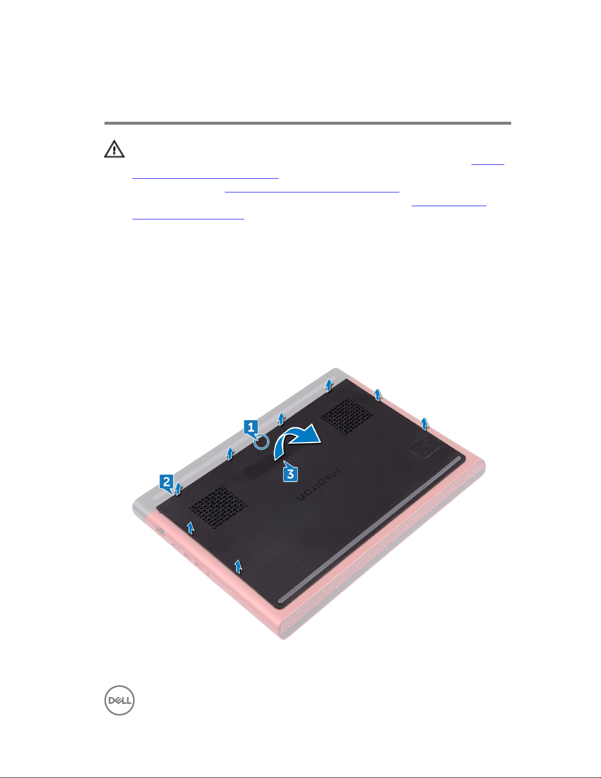
Procedure
1 Loosen the captive screw that secures the base cover to the computer base.
2 Using your ngertips, gently pry the base cover to release the tabs from the slots
on the computer base.
3 Lift the base cover o the computer base.
15
Page 3
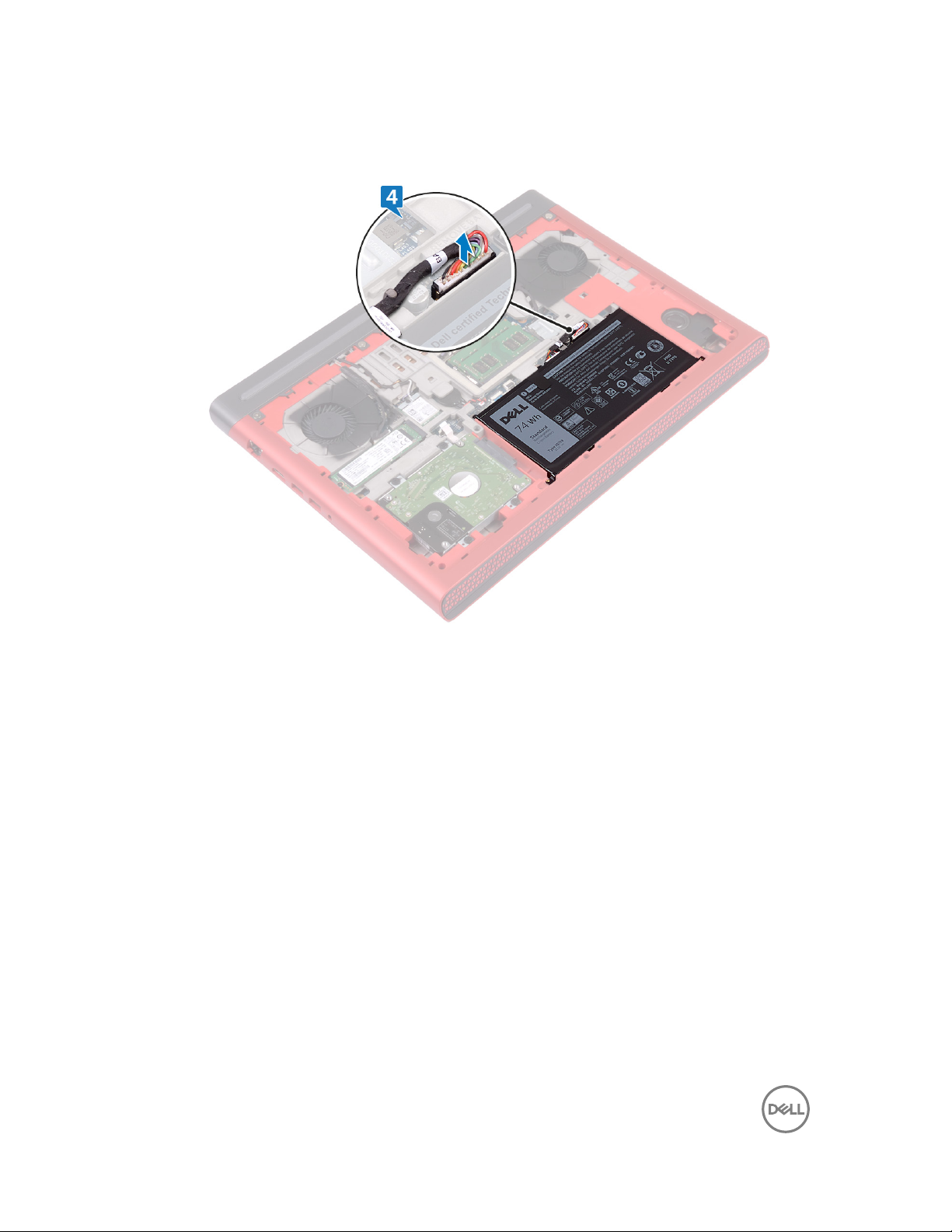
4 Disconnect the battery cable from the system board.
16
Page 4

Removing the battery
WARNING: Before working inside your computer, read the safety
information that shipped with your computer and follow the steps in Before
working inside your computer. After working inside your computer, follow
the instructions in After working inside your computer. For more safety best
practices, see the Regulatory Compliance home page at
www.dell.com/
regulatory_compliance.
Prerequisites
Remove the base cover.
Procedure
1 Remove the battery cable from the routing guide on the computer base.
2 Remove the ve screws (M2x4 T8) that secure the battery to the computer
base.
18
Page 5
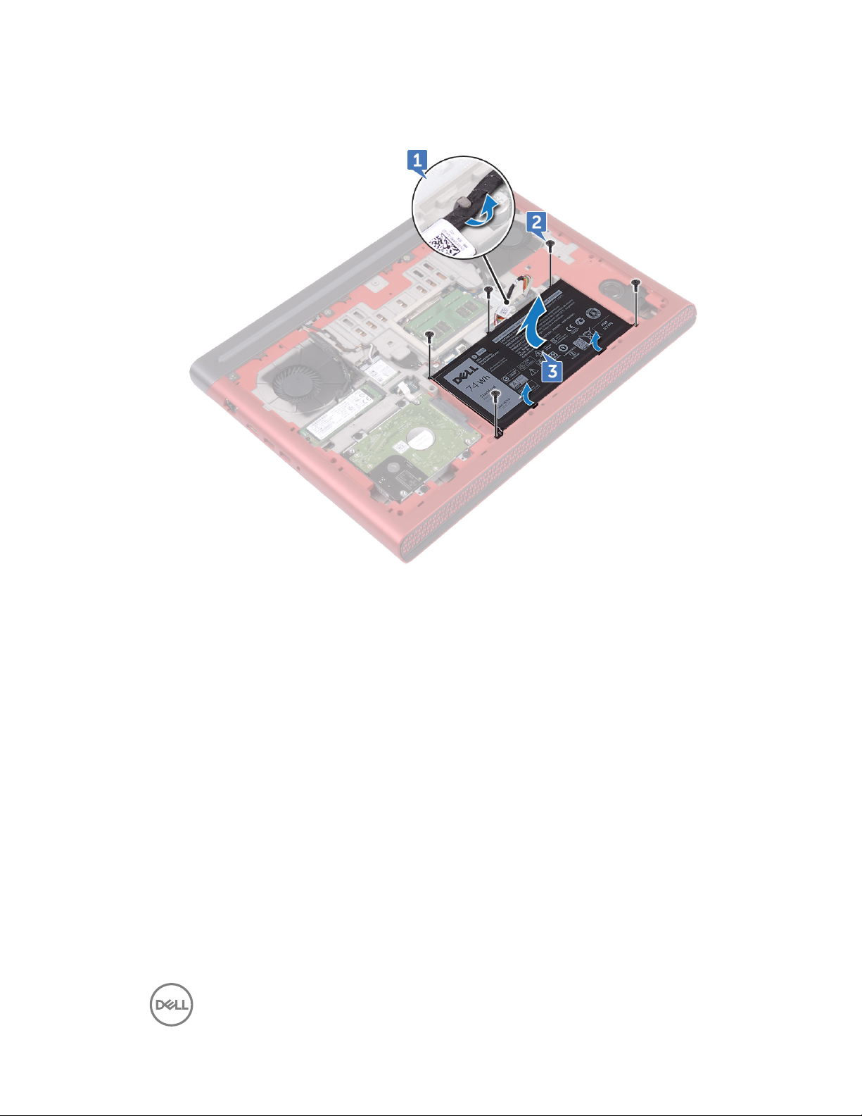
3 Lift the battery at an angle o the computer base.
4 Turn the computer over, open the display, and press and hold the power button
for ve seconds to ground the system board.
19
Page 6

Removing the rear cover
WARNING: Before working inside your computer, read the safety
information that shipped with your computer and follow the steps in Before
working inside your computer. After working inside your computer, follow
the instructions in After working inside your computer. For more safety best
practices, see the Regulatory Compliance home page at
www.dell.com/
regulatory_compliance.
Prerequisites
Remove the base cover.
Procedure
1 Remove the four screws (M2x3 Big head) that secure the rear cover to the
computer base.
40
Page 7
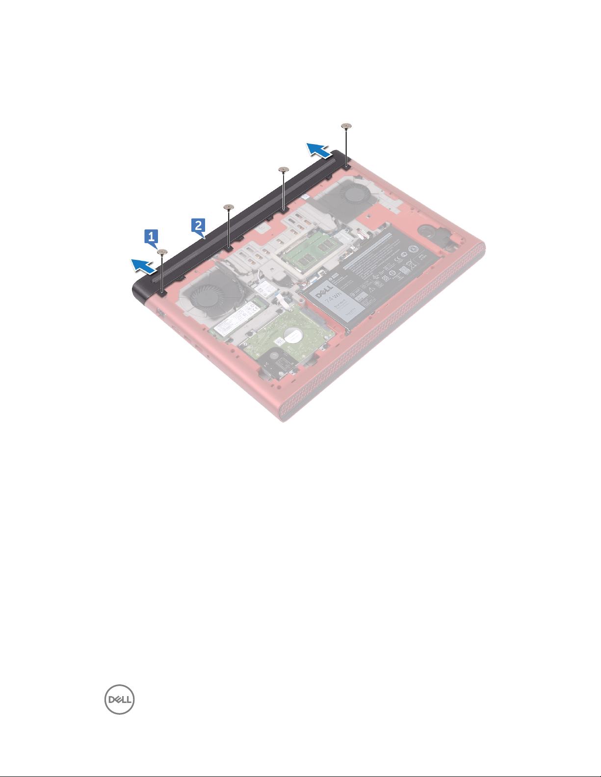
2 Slide and remove the rear cover from the computer base.
41
Page 8

Removing the palm rest and
keyboard assembly
WARNING: Before working inside your computer, read the safety
information that shipped with your computer and follow the steps in Before
working inside your computer. After working inside your computer, follow
the instructions in After working inside your computer. For more safety best
practices, see the Regulatory Compliance home page at www.dell.com/
regulatory_compliance.
Prerequisites
1 Remove the base cover.
2 Remove the battery.
3 Remove the rear cover.
Procedure
1 Open the latches and disconnect the touch-pad cable and keyboard-backlit cable
from the system board.
2 Remove the 15 screws (M2.5x5) that secure the palm rest and keyboard
assembly to the computer base.
43
Page 9
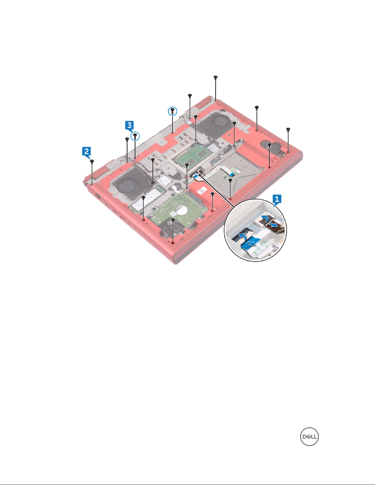
3 Remove the two screws (M2.5x8) that secure the palm rest and keyboard
assembly to the computer base.
4 Turn the computer over and open the display.
44
Page 10
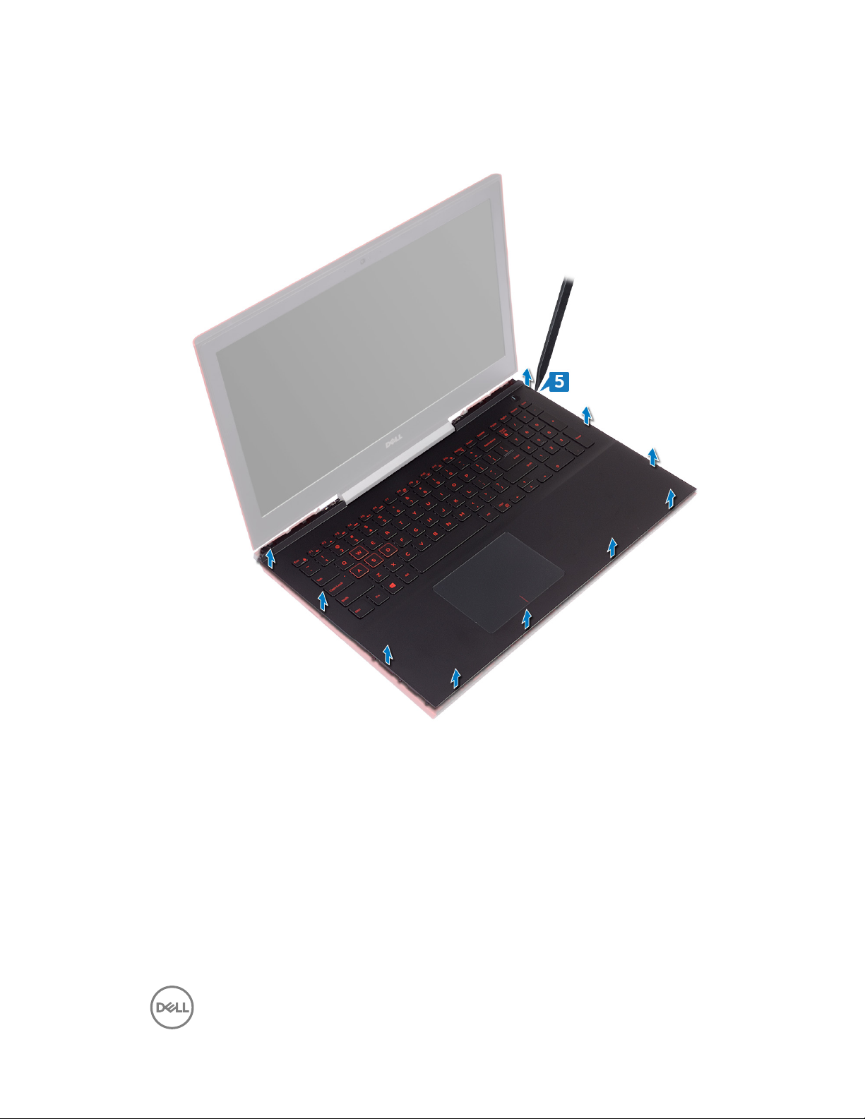
5 Using a plastic scribe, release the tabs on palm rest and keyboard assembly from
the slots on the computer base.
6 Lift the palm rest and keyboard assembly at an angle.
45
Page 11
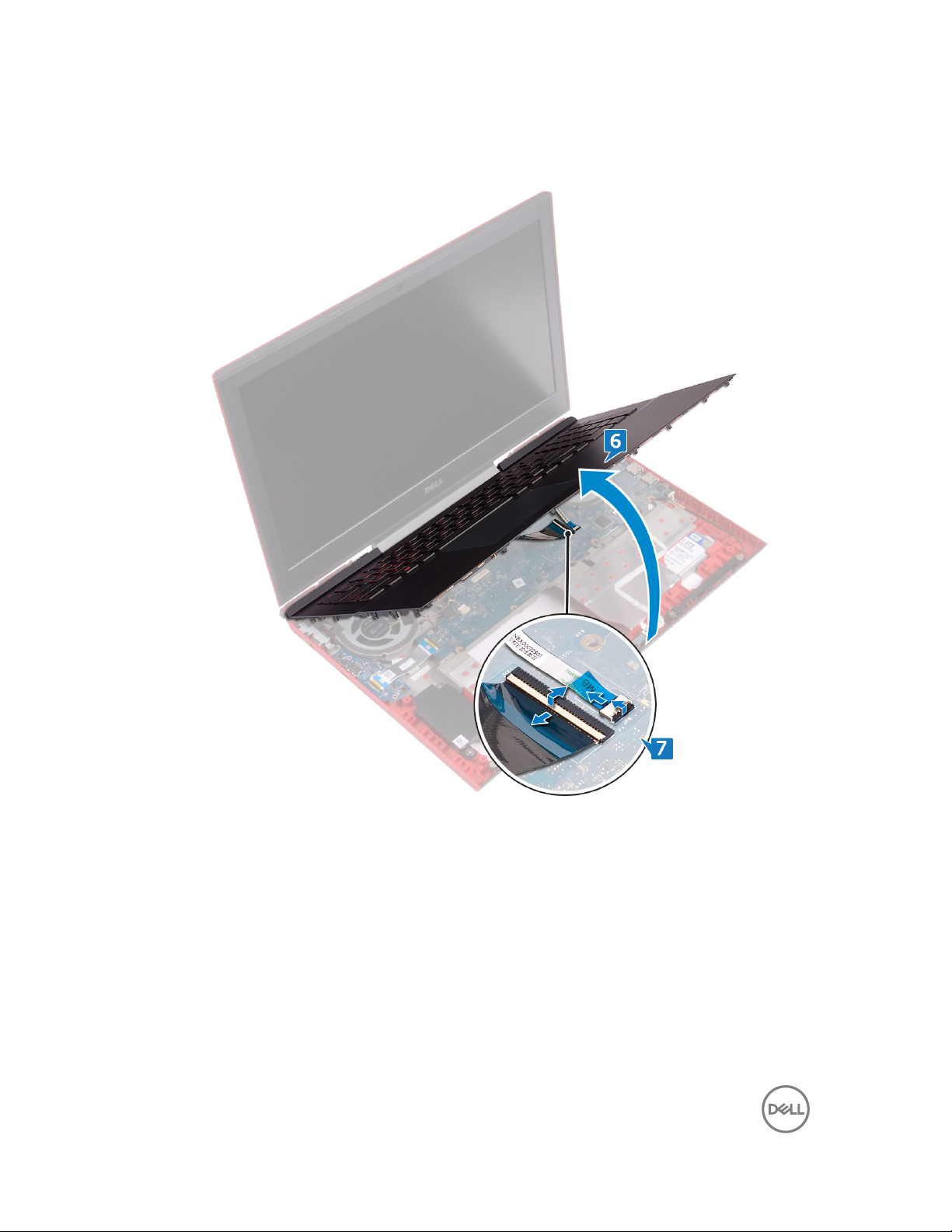
7 Open the latches and disconnect the keyboard cable and the power-button
board cable from the system board.
46
Page 12
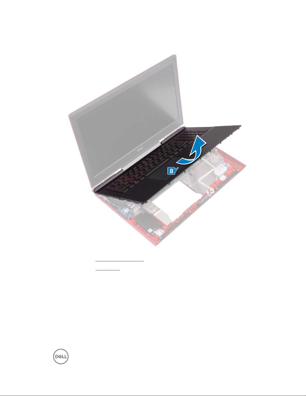
8 Lift the palm rest and keyboard assembly o the computer base.
9 Remove the power-button board.
10 Remove the touch pad.
47
Page 13

Removing the fans
WARNING: Before working inside your computer, read the safety
information that shipped with your computer and follow the steps in Before
working inside your computer. After working inside your computer, follow
the instructions in After working inside your computer. For more safety best
practices, see the Regulatory Compliance home page at
www.dell.com/
regulatory_compliance.
Prerequisites
1 Remove the base cover.
2 Remove the battery.
3 Remove the rear cover.
4 Follow the procedure from step 1 to step 8 in “Removing the palm rest and
keyboard assembly”.
Procedure
1 Disconnect the left-fan cable from the system board.
2 Peel o the tape that secures the left-fan cable to the system board.
3 Remove the three screws (M2x3) that secure the left fan to the system board.
53
Page 14

4 Lift the left fan, along with its cable, o the computer base.
5 Disconnect the right-fan cable from the system board.
6 Remove the three screws (M2x3) that secure the right fan to the system board.
54
Page 15

7 Lift the right fan, along with its cable, o the computer base.
55
Page 16

Removing the memory modules
WARNING: Before working inside your computer, read the safety
information that shipped with your computer and follow the steps in Before
working inside your computer. After working inside your computer, follow
the instructions in After working inside your computer. For more safety best
practices, see the Regulatory Compliance home page at
www.dell.com/
regulatory_compliance.
Prerequisites
Remove the base cover.
Procedure
1 Use your ngertips to carefully spread apart the securing-clips on each end of
the memory-module slot until the memory module pops up.
21
Page 17

2 Remove the memory module from the memory-module slot.
22
Page 18

Removing the solid-state drive
WARNING: Before working inside your computer, read the safety
information that shipped with your computer and follow the steps in Before
working inside your computer. After working inside your computer, follow
the instructions in After working inside your computer. For more safety best
practices, see the Regulatory Compliance home page at
www.dell.com/
regulatory_compliance.
CAUTION: Solid-state drives are fragile. Exercise care when handling the
solid-state drive.
CAUTION: To avoid data loss, do not remove the solid-state drive while the
computer is in sleep or on state.
Prerequisites
Remove the base cover.
Procedure
1 Remove the screw (M2x3) that secures the solid-state drive to the computer
base.
29
Page 19

2 Slide and remove the solid-state drive from the solid-state drive slot.
30
Page 20

Removing the wireless card
WARNING: Before working inside your computer, read the safety
information that shipped with your computer and follow the steps in Before
working inside your computer. After working inside your computer, follow
the instructions in After working inside your computer. For more safety best
practices, see the Regulatory Compliance home page at
www.dell.com/
regulatory_compliance.
Prerequisites
Remove the base cover.
Procedure
1 Remove the screw (M2x3) that secures the wireless-card bracket to the to the
wireless card and system board.
2 Remove the wireless-card bracket from the wireless card.
3 Disconnect the antenna cables from the wireless card.
33
Page 21

4 Slide and remove the wireless card from the wireless-card slot.
34
Page 22

Removing the system board
WARNING: Before working inside your computer, read the safety
information that shipped with your computer and follow the steps in Before
working inside your computer. After working inside your computer, follow
the instructions in After working inside your computer. For more safety best
practices, see the Regulatory Compliance home page at
www.dell.com/
regulatory_compliance.
NOTE: Your computer’s Service Tag is stored in the system board. You must
enter the Service Tag in the BIOS setup program after you replace the
system board.
NOTE: Replacing the system board removes any changes you have made to
the BIOS using the BIOS setup program. You must make the appropriate
changes again after you replace the system board.
NOTE: Before disconnecting the cables from the system board, note the
location of the connectors so that you can reconnect the cables correctly
after you replace the system board.
Prerequisites
1 Remove the base cover.
2 Remove the battery.
3 Remove the rear cover.
4 Remove the memory modules.
5 Remove the solid-state drive.
6 Remove the wireless card.
7 Follow the procedure from step 1 to step 8 in “Removing the palm rest and
keyboard assembly”.
8 Remove the fans.
Procedure
1 Remove the screw (M2x3) that secures the display-cable bracket to the system
board.
69
Page 23

2 Lift the display-cable bracket o the system board.
3 Using the pull-tab, disconnect the display cable from the system board.
4 Disconnect the coin-cell battery cable from the system board.
5 Using the pull-tab, disconnect the hard-drive cable from the system board.
6 Using the pull tab, disconnect the camera cable from the system board.
7 Turn the computer over and open the display as far as possible.
8 Disconnect the speaker cable from the system board.
9 Open the latch and disconnect the status-light board cable from the system
board.
70
Page 24

10 Open the latch and disconnect the I/O board cable from the system board.
11 Remove the two screws (M2x3) that secure the system board to the computer
base.
12 Gently release the ports on the system board from the slots on the computer
base.
71
Page 25

13 Lift the system board at an angle and turn the system board over.
14 Disconnect the power-adapter port cable from the system board.
72
Page 26

15 Remove the heat sink.
73
Page 27

Removing the power-adapter
port
WARNING: Before working inside your computer, read the safety
information that shipped with your computer and follow the steps in Before
working inside your computer. After working inside your computer, follow
the instructions in After working inside your computer. For more safety best
practices, see the Regulatory Compliance home page at www.dell.com/
regulatory_compliance.
Prerequisites
1 Remove the base cover.
2 Remove the battery.
3 Remove the rear cover.
4 Follow the procedure from step 1 to step 8 in “Removing the palm rest and
keyboard assembly”.
5 Remove the fans.
6 Remove the system board.
Procedure
1 Remove the four screws (M2x3) that secure the power-adapter port bracket to
the computer base.
2 Lift the power-adapter port bracket o the computer base.
3 Remove the power-adapter cable from the routing guides on the computer base.
79
Page 28

4 Lift the power-adapter port, along with its cable, o the computer base.
80
Page 29

Replacing the power-adapter
port
WARNING: Before working inside your computer, read the safety
information that shipped with your computer and follow the steps in Before
working inside your computer. After working inside your computer, follow
the instructions in After working inside your computer. For more safety best
practices, see the Regulatory Compliance home page at www.dell.com/
regulatory_compliance.
Procedure
1 Place the power-adapter port into the slot on the computer base.
2 Align the screw holes on the power-adapter port bracket with the screw holes
on the computer base.
3 Replace the four screws (M2x3) that secure the power-adapter port bracket to
the computer base.
4 Route the power-adapter port cable through the routing guides on the computer
base.
5 Connect the power-adapter port cable to the system board.
Post-requisites
1 Replace the system board.
2 Replace the fans.
3 Follow the procedure from step 3 to step 9 in “Replacing the palm rest and
keyboard assembly”.
4 Replace the rear cover.
5 Replace the base cover.
6 Replace the battery.
81
Page 30

Replacing the system board
WARNING: Before working inside your computer, read the safety
information that shipped with your computer and follow the steps in Before
working inside your computer. After working inside your computer, follow
the instructions in After working inside your computer. For more safety best
practices, see the Regulatory Compliance home page at
www.dell.com/
regulatory_compliance.
NOTE: Your computer’s Service Tag is stored in the system board. You must
enter the Service Tag in the BIOS setup program after you replace the
system board.
NOTE: Replacing the system board removes any changes you have made to
the BIOS using the BIOS setup program. You must make the appropriate
changes again after you replace the system board.
Procedure
1 Replace the heat sink.
2 Connect the power-adapter port cable to the system board.
3 Turn the system board over.
4 Slide the ports on the system board into the slots on the computer base and
align the screw holes on the system board with the screw holes on the computer
base.
5 Replace the two screws (M2x3) that secure the system board to the computer
base.
6 Slide the I/O-board cable and status-light board cable into their respective
connectors on the system board and close the latches to secure the cables.
7 Connect the speaker cable to the system board.
8 Close the display and turn the computer over.
9 Connect the camera cable, hard-drive cable, coin-cell battery cable and display
cable to the system board.
10 Align the screw hole on the display-cable bracket with the screw hole on the
system board.
11 Replace the screw (M2x3) that secures the display-cable bracket to the system
board.
74
Page 31

Post-requisites
1 Replace the fans.
2 Follow the procedure from step 3 to step 9 in “Replacing the palm rest and
keyboard assembly”.
3 Replace the wireless card.
4 Replace the solid-state drive.
5 Replace the memory modules.
6 Replace the rear cover.
7 Replace the battery.
8 Replace the base cover.
75
Page 32

Replacing the fans
WARNING: Before working inside your computer, read the safety
information that shipped with your computer and follow the steps in Before
working inside your computer. After working inside your computer, follow
the instructions in After working inside your computer. For more safety best
practices, see the Regulatory Compliance home page at
www.dell.com/
regulatory_compliance.
Procedure
1 Align the screw holes on the left fan with the screw holes on the computer base.
2 Replace the three screws (M2x3) that secure the left fan to the computer base.
3 Connect the left-fan cable to the system board.
4 Adhere the tape that secures the left-fan cable to the system board.
5 Align the screw holes on the right fan with the screw holes on the computer
base.
6 Replace the three screws (M2x3) that secure the right fan to the computer
base.
7 Connect the right-fan cable to the system board.
Post-requisites
1 Follow the procedure from step 3 to step 9 in “Replacing the palm rest and
keyboard assembly”.
2 Replace the rear cover.
3 Replace the battery.
4 Replace the base cover.
56
Page 33

Replacing the palm rest and
keyboard assembly
WARNING: Before working inside your computer, read the safety
information that shipped with your computer and follow the steps in Before
working inside your computer. After working inside your computer, follow
the instructions in After working inside your computer. For more safety best
practices, see the Regulatory Compliance home page at www.dell.com/
regulatory_compliance.
Procedure
1 Replace the touch pad.
2 Replace the power-button board.
3 Align and place the palm rest and keyboard assembly on the computer base.
4 Slide the keyboard cable and the power-button board cable into the connectors
on the system board and close the latches to secure the cables.
5 Press down the edges of the palm rest and keyboard assembly and snap it into
place.
6 Close the display and turn the computer over.
7 Replace the 15 screws (M2.5x5) that secure the palm rest and keyboard
assembly to the computer base.
8 Replace the two screw (M2.5x8) that secure the palm rest and keyboard
assembly to the computer base.
9 Slide the touch-pad cable and the keyboard-backlit cable into the connectors on
the system board and close the latches to secure the cables.
Post-requisites
1 Replace the rear cover.
2 Replace the battery.
3 Replace the base cover.
49
Page 34

Replacing the wireless card
WARNING: Before working inside your computer, read the safety
information that shipped with your computer and follow the steps in Before
working inside your computer. After working inside your computer, follow
the instructions in After working inside your computer. For more safety best
practices, see the Regulatory Compliance home page at
www.dell.com/
regulatory_compliance.
Procedure
CAUTION: To avoid damage to the wireless card, do not place any cables
under it.
1 Align the notch on the wireless card with the tab on the wireless-card slot.
2 Slide the wireless card at an angle into the wireless-card slot.
3 Connect the antenna cables to the wireless card.
The following table provides the antenna-cable color scheme for the wireless
card supported by your computer.
Table 2. Antenna-cable color scheme
Connectors on the wireless card Antenna-cable color
Main (white triangle) White
Auxiliary (black triangle) Black
4 Align the screw hole on the wireless-card bracket with the screw hole on the
wireless card and the system board.
35
Page 35

5 Replace the screw (M2x3) that secures the wireless-card bracket to the wireless
card and system board.
Post-requisites
Replace the base cover.
36
Page 36

Replacing the solid-state drive
WARNING: Before working inside your computer, read the safety
information that shipped with your computer and follow the steps in Before
working inside your computer. After working inside your computer, follow
the instructions in After working inside your computer. For more safety best
practices, see the Regulatory Compliance home page at
www.dell.com/
regulatory_compliance.
CAUTION: Solid-state drives are fragile. Exercise care when handling the
solid-state drive.
Procedure
1 Align the notch on the solid-state drive with the tab on the solid-state drive slot
and slide the solid-state drive into the solid-state drive slot.
2 Press the other end of the solid-state drive to align the screw hole on the solid-
state drive with the screw hole on the computer base.
31
Page 37

3 Replace the screw (M2x3) that secures the solid-state drive to the computer
base.
Post-requisites
Replace the base cover.
32
Page 38

Replacing the memory modules
WARNING: Before working inside your computer, read the safety
information that shipped with your computer and follow the steps in Before
working inside your computer. After working inside your computer, follow
the instructions in After working inside your computer. For more safety best
practices, see the Regulatory Compliance home page at
www.dell.com/
regulatory_compliance.
Procedure
1 Align the notch on the memory module with the tab on the memory-module slot
and slide it rmly into the slot at an angle.
23
Page 39

2 Press the memory module down until it clicks into place.
NOTE: If you do not hear the click, remove the memory module and
reinstall it.
Post-requisites
Replace the base cover.
24
Page 40

Replacing the rear cover
WARNING: Before working inside your computer, read the safety
information that shipped with your computer and follow the steps in Before
working inside your computer. After working inside your computer, follow
the instructions in After working inside your computer. For more safety best
practices, see the Regulatory Compliance home page at
www.dell.com/
regulatory_compliance.
Procedure
1 Slide the tabs on the rear cover into the slots on the computer base and snap
the rear cover into place.
2 Align the screw holes on the rear cover with the screw holes on the computer
base.
3 Replace the four screws (M2x3 Big head) that secure the rear cover to the
computer base.
Post-requisites
Replace the base cover.
42
Page 41

Replacing the battery
WARNING: Before working inside your computer, read the safety
information that shipped with your computer and follow the steps in Before
working inside your computer. After working inside your computer, follow
the instructions in After working inside your computer. For more safety best
practices, see the Regulatory Compliance home page at
www.dell.com/
regulatory_compliance.
Procedure
1 Slide the battery in the slot on the computer base and align the screw holes on
the battery with the screw holes on the computer base.
2 Replace the ve screws (M2x4 T8) that secure the battery to the computer
base.
3 Route the battery cable through the routing guides on the computer base.
Post-requisites
Replace the base cover.
20
Page 42

Replacing the base cover
WARNING: Before working inside your computer, read the safety
information that shipped with your computer and follow the steps in Before
working inside your computer. After working inside your computer, follow
the instructions in After working inside your computer. For more safety best
practices, see the Regulatory Compliance home page at
www.dell.com/
regulatory_compliance.
Procedure
1 Connect the battery cable to the system board.
2 Slide the tabs on the base cover into the slots on the computer base and snap
the base cover into place.
3 Tighten the captive screw that secures the base cover to the computer base.
17
 Loading...