

Page 1

Inspiron 3793
Service Manual
Regulatory Model: P35E
Regulatory Type: P35E007
Page 2

Notes, cautions, and warnings
NOTE: A NOTE indicates important information that helps you make better use of your product.
CAUTION: A CAUTION indicates either potential damage to hardware or loss of data and tells you how to avoid the
problem.
WARNING: A WARNING indicates a potential for property damage, personal injury, or death.
© 2019 Dell Inc. or its subsidiaries. All rights reserved. Dell, EMC, and other trademarks are trademarks of Dell Inc. or its subsidiaries.
Other trademarks may be trademarks of their respective owners.
2019 - 08
Rev. A00
Page 3

Contents
1 Before working inside your computer............................................................................................. 9
Before you begin ...................................................................................................................................................................9
2 After working inside your computer..............................................................................................10
3 Safety instructions...................................................................................................................... 11
Electrostatic discharge—ESD protection......................................................................................................................... 11
ESD field service kit ............................................................................................................................................................ 12
Transporting sensitive components...................................................................................................................................13
4 Recommended tools....................................................................................................................14
5 Screw list...................................................................................................................................15
6 Removing the optical drive...........................................................................................................17
Procedure..............................................................................................................................................................................17
7 Replacing the optical drive...........................................................................................................19
Procedure .............................................................................................................................................................................19
8 Removing the base cover.............................................................................................................21
Prerequisites......................................................................................................................................................................... 21
Procedure..............................................................................................................................................................................21
9 Replacing the base cover............................................................................................................ 23
Procedure ............................................................................................................................................................................23
Post-requisites.....................................................................................................................................................................24
10 Removing the battery................................................................................................................25
Lithium-ion battery precautions........................................................................................................................................ 25
Prerequisites........................................................................................................................................................................ 25
Procedure.............................................................................................................................................................................25
11 Replacing the battery.................................................................................................................27
Lithium-ion battery precautions.........................................................................................................................................27
Procedure ............................................................................................................................................................................ 27
Post-requisites.....................................................................................................................................................................28
12 Removing the memory modules..................................................................................................29
Prerequisites........................................................................................................................................................................ 29
Procedure.............................................................................................................................................................................29
13 Replacing the memory modules.................................................................................................. 30
Contents 3
Page 4

Procedure ............................................................................................................................................................................30
Post-requisites.....................................................................................................................................................................30
14 Removing the wireless card........................................................................................................ 31
Prerequisites......................................................................................................................................................................... 31
Procedure..............................................................................................................................................................................31
15 Replacing the wireless card........................................................................................................33
Procedure............................................................................................................................................................................. 33
Post-requisites.....................................................................................................................................................................33
16 Removing the optical-drive connector board............................................................................... 34
Prerequisites.........................................................................................................................................................................34
Procedure............................................................................................................................................................................. 34
17 Replacing the optical-drive connector board................................................................................35
Procedure ............................................................................................................................................................................35
Post-requisites.....................................................................................................................................................................35
18 Removing the coin-cell battery...................................................................................................36
Prerequisites........................................................................................................................................................................ 36
Procedure.............................................................................................................................................................................36
19 Replacing the coin-cell battery................................................................................................... 37
Procedure............................................................................................................................................................................. 37
Post-requisites..................................................................................................................................................................... 37
20 Removing the fan..................................................................................................................... 38
Prerequisites.........................................................................................................................................................................38
Procedure............................................................................................................................................................................. 38
21 Replacing the fan...................................................................................................................... 40
Procedure ............................................................................................................................................................................40
Post-requisites......................................................................................................................................................................41
22 Removing the solid-state drive/Intel Optane...............................................................................42
Prerequisites.........................................................................................................................................................................42
Procedure to remove the M.2 2230 solid-state drive.................................................................................................... 42
Procedure to remove the M.2 2280 solid-state drive/Intel Optane.............................................................................43
23 Replacing the solid-state drive/Intel Optane............................................................................... 44
Procedure to replace the M.2 2230 solid-state drive.....................................................................................................44
Procedure to replace the M.2 2280 solid-state drive/Intel Optane............................................................................. 45
Post-requisites.....................................................................................................................................................................45
24 Removing the hard drive........................................................................................................... 46
Prerequisites........................................................................................................................................................................ 46
Procedure.............................................................................................................................................................................46
4
Contents
Page 5

25 Replacing the hard drive........................................................................................................... 48
Procedure ............................................................................................................................................................................48
Post-requisites.....................................................................................................................................................................49
26 Removing the touchpad............................................................................................................ 50
Prerequisites........................................................................................................................................................................ 50
Procedure.............................................................................................................................................................................50
27 Replacing the touchpad.............................................................................................................52
Procedure ............................................................................................................................................................................52
Post-requisites.....................................................................................................................................................................53
28 Removing the speakers............................................................................................................. 54
Prerequisites........................................................................................................................................................................ 54
Procedure.............................................................................................................................................................................54
29 Replacing the speakers............................................................................................................. 55
Procedure ............................................................................................................................................................................55
Post-requisites.....................................................................................................................................................................55
30 Removing the heat sink.............................................................................................................56
Prerequisites........................................................................................................................................................................ 56
Procedure.............................................................................................................................................................................56
31 Replacing the heat sink..............................................................................................................57
Procedure ............................................................................................................................................................................ 57
Post-requisites.....................................................................................................................................................................57
32 Removing the power-adapter port............................................................................................. 58
Removing the display assembly.........................................................................................................................................58
Prerequisites...................................................................................................................................................................58
Procedure....................................................................................................................................................................... 58
Procedure.............................................................................................................................................................................60
33 Replacing the power-adapter port..............................................................................................62
Procedure ............................................................................................................................................................................62
Replacing the display assembly..........................................................................................................................................62
Procedure ...................................................................................................................................................................... 62
Post-requisites............................................................................................................................................................... 64
34 Removing the display assembly..................................................................................................65
Prerequisites........................................................................................................................................................................ 65
Procedure.............................................................................................................................................................................65
35 Replacing the display assembly..................................................................................................68
Procedure ............................................................................................................................................................................68
Post-requisites.....................................................................................................................................................................69
Contents
5
Page 6

36 Removing the I/O board............................................................................................................ 70
Prerequisites.........................................................................................................................................................................70
Procedure............................................................................................................................................................................. 70
37 Replacing the I/O board............................................................................................................. 71
Procedure .............................................................................................................................................................................71
Post-requisites......................................................................................................................................................................71
38 Removing the power-button board.............................................................................................72
Prerequisites.........................................................................................................................................................................72
Procedure............................................................................................................................................................................. 72
39 Replacing the power-button board............................................................................................. 74
Procedure ............................................................................................................................................................................ 74
Post-requisites.....................................................................................................................................................................75
40 Removing the system board...................................................................................................... 76
Prerequisites.........................................................................................................................................................................76
Procedure............................................................................................................................................................................. 76
41 Replacing the system board....................................................................................................... 79
Procedure............................................................................................................................................................................. 79
Post-requisites.....................................................................................................................................................................80
Entering the Service Tag in the BIOS setup program..................................................................................................... 81
42 Removing the power button with fingerprint reader.................................................................... 82
Prerequisites.........................................................................................................................................................................82
Procedure............................................................................................................................................................................. 82
43 Replacing the power button with fingerprint reader.....................................................................83
Procedure ............................................................................................................................................................................83
Post-requisites.....................................................................................................................................................................83
44 Removing the palm-rest and keyboard assembly......................................................................... 84
Prerequisites.........................................................................................................................................................................84
Procedure............................................................................................................................................................................. 84
45 Replacing the palm-rest and keyboard assembly......................................................................... 86
Procedure ............................................................................................................................................................................86
Post-requisites.....................................................................................................................................................................86
46 Removing the display bezel........................................................................................................87
Prerequisites.........................................................................................................................................................................87
Procedure............................................................................................................................................................................. 87
47 Replacing the display bezel........................................................................................................88
Procedure ............................................................................................................................................................................88
6
Contents
Page 7

Post-requisites.....................................................................................................................................................................88
48 Removing the camera............................................................................................................... 89
Prerequisites........................................................................................................................................................................ 89
Procedure.............................................................................................................................................................................89
49 Replacing the camera............................................................................................................... 90
Procedure ............................................................................................................................................................................90
Post-requisites.....................................................................................................................................................................90
50 Removing the display panel........................................................................................................91
Prerequisites......................................................................................................................................................................... 91
Procedure..............................................................................................................................................................................91
51 Replacing the display panel........................................................................................................93
Procedure ............................................................................................................................................................................93
Post-requisites.....................................................................................................................................................................94
52 Removing the display hinges..................................................................................................... 95
Prerequisites........................................................................................................................................................................ 95
Procedure.............................................................................................................................................................................95
53 Replacing the display hinges......................................................................................................96
Procedure ............................................................................................................................................................................96
Post-requisites.....................................................................................................................................................................96
54 Removing the display cable....................................................................................................... 97
Prerequisites.........................................................................................................................................................................97
Procedure............................................................................................................................................................................. 97
55 Replacing the display cable....................................................................................................... 98
Procedure ............................................................................................................................................................................98
Post-requisites.....................................................................................................................................................................98
56 Removing the display back-cover and antenna assembly..............................................................99
Prerequisites........................................................................................................................................................................ 99
Procedure.............................................................................................................................................................................99
57 Replacing the display back-cover and antenna assembly.............................................................100
Procedure .......................................................................................................................................................................... 100
Post-requisites................................................................................................................................................................... 100
58 Device drivers......................................................................................................................... 101
Intel Chipset Software Installation Utility.........................................................................................................................101
Downloading the graphics driver...................................................................................................................................... 101
Intel Serial IO driver............................................................................................................................................................ 101
Intel Trusted Execution Engine Interface........................................................................................................................ 101
Intel Virtual Button driver...................................................................................................................................................101
Contents
7
Page 8

Wireless and Bluetooth drivers.........................................................................................................................................102
59 System setup..........................................................................................................................103
BIOS overview....................................................................................................................................................................103
Entering BIOS setup program.......................................................................................................................................... 103
Navigation keys.................................................................................................................................................................. 103
Boot Sequence...................................................................................................................................................................103
System setup options........................................................................................................................................................104
System and setup password............................................................................................................................................ 108
Assigning a system setup password..........................................................................................................................108
Deleting or changing an existing system setup password...................................................................................... 109
Clearing CMOS settings..............................................................................................................................................109
Clearing BIOS (System Setup) and System passwords......................................................................................... 109
60 Troubleshooting...................................................................................................................... 110
Enhanced Pre-Boot System Assessment (ePSA) diagnostics.....................................................................................110
Running the ePSA diagnostics.................................................................................................................................... 110
System diagnostic lights.................................................................................................................................................... 110
Recovering the operating system..................................................................................................................................... 111
Flashing BIOS (USB key)....................................................................................................................................................111
Flashing the BIOS............................................................................................................................................................... 112
WiFi power cycle.................................................................................................................................................................112
Enabling Intel Optane memory.......................................................................................................................................... 112
Disabling Intel Optane memory......................................................................................................................................... 112
Flea power release..............................................................................................................................................................113
61 Getting help and contacting Dell................................................................................................114
8
Contents
Page 9

Before working inside your computer
NOTE: The images in this document may differ from your computer depending on the configuration you ordered.
Before you begin
1. Save and close all open files and exit all open applications.
2. Shut down your computer. Click Start > Power > Shut down.
NOTE: If you are using a different operating system, see the documentation of your operating system for shut-down
instructions.
3. Disconnect your computer and all attached devices from their electrical outlets.
4. Disconnect all attached network devices and peripherals, such as keyboard, mouse, and monitor from your computer.
5. Remove any media card and optical disc from your computer, if applicable.
1
Before working inside your computer 9
Page 10

After working inside your computer
CAUTION: Leaving stray or loose screws inside your computer may severely damage your computer.
1. Replace all screws and ensure that no stray screws remain inside your computer.
2. Connect any external devices, peripherals, or cables you removed before working on your computer.
3. Replace any media cards, discs, or any other parts that you removed before working on your computer.
4. Connect your computer and all attached devices to their electrical outlets.
5. Turn on your computer.
2
10 After working inside your computer
Page 11

3
Safety instructions
Use the following safety guidelines to protect your computer from potential damage and to ensure your personal safety. Unless otherwise
noted, each procedure included in this document assumes that you have read the safety information that shipped with your computer.
NOTE: Before working inside your computer, read the safety information that shipped with your computer. For more
safety best practices, see the Regulatory Compliance home page at www.dell.com/regulatory_compliance.
NOTE: Disconnect all power sources before opening the computer cover or panels. After you finish working inside the
computer, replace all covers, panels, and screws before connecting to the electrical outlet.
CAUTION: To avoid damaging the computer, ensure that the work surface is flat and clean.
CAUTION: Handle components and cards with care. Do not touch the components or contacts on a card. Hold a card by
its edges or by its metal mounting bracket. Hold a component such as a processor by its edges, not by its pins.
CAUTION: You should only perform troubleshooting and repairs as authorized or directed by the Dell technical
assistance team. Damage due to servicing that is not authorized by Dell is not covered by your warranty. See the safety
instructions that shipped with the product or at www.dell.com/regulatory_compliance.
CAUTION: Before touching anything inside your computer, ground yourself by using a wrist grounding strap or by
periodically touching an unpainted metal surface, such as the metal at the back of the computer. While you work,
periodically touch an unpainted metal surface to dissipate static electricity, which could harm internal components.
CAUTION: When you disconnect a cable, pull on its connector or on its pull tab, not on the cable itself. Some cables have
connectors with locking tabs or thumb-screws that you must disengage before disconnecting the cable. When
disconnecting cables, keep them evenly aligned to avoid bending any connector pins. When connecting cables, ensure
that the ports and connectors are correctly oriented and aligned.
CAUTION: Press and eject any installed card from the media-card reader.
NOTE: The color of your computer and certain components may appear differently than shown in this document.
Electrostatic discharge—ESD protection
ESD is a major concern when you handle electronic components, especially sensitive components such as expansion cards, processors,
memory DIMMs, and system boards. Very slight charges can damage circuits in ways that may not be obvious, such as intermittent
problems or a shortened product life span. As the industry pushes for lower power requirements and increased density, ESD protection is
an increasing concern.
Due to the increased density of semiconductors used in recent Dell products, the sensitivity to static damage is now higher than in
previous Dell products. For this reason, some previously approved methods of handling parts are no longer applicable.
Two recognized types of ESD damage are catastrophic and intermittent failures.
• Catastrophic – Catastrophic failures represent approximately 20 percent of ESD-related failures. The damage causes an immediate
and complete loss of device functionality. An example of catastrophic failure is a memory DIMM that has received a static shock and
immediately generates a "No POST/No Video" symptom with a beep code emitted for missing or nonfunctional memory.
• Intermittent – Intermittent failures represent approximately 80 percent of ESD-related failures. The high rate of intermittent failures
means that most of the time when damage occurs, it is not immediately recognizable. The DIMM receives a static shock, but the
tracing is merely weakened and does not immediately produce outward symptoms related to the damage. The weakened trace may
take weeks or months to melt, and in the meantime may cause degradation of memory integrity, intermittent memory errors, etc.
The more difficult type of damage to recognize and troubleshoot is the intermittent (also called latent or "walking wounded") failure.
Perform the following steps to prevent ESD damage:
Safety instructions 11
Page 12

• Use a wired ESD wrist strap that is properly grounded. The use of wireless anti-static straps is no longer allowed; they do not provide
adequate protection. Touching the chassis before handling parts does not ensure adequate ESD protection on parts with increased
sensitivity to ESD damage.
• Handle all static-sensitive components in a static-safe area. If possible, use anti-static floor pads and workbench pads.
• When unpacking a static-sensitive component from its shipping carton, do not remove the component from the anti-static packing
material until you are ready to install the component. Before unwrapping the anti-static packaging, ensure that you discharge static
electricity from your body.
• Before transporting a static-sensitive component, place it in an anti-static container or packaging.
ESD field service kit
The unmonitored Field Service kit is the most commonly used service kit. Each Field Service kit includes three main components: antistatic mat, wrist strap, and bonding wire.
Components of an ESD field service kit
The components of an ESD field service kit are:
• Anti-Static Mat – The anti-static mat is dissipative and parts can be placed on it during service procedures. When using an antistatic mat, your wrist strap should be snug and the bonding wire should be connected to the mat and to any bare metal on the system
being worked on. Once deployed properly, service parts can be removed from the ESD bag and placed directly on the mat. ESDsensitive items are safe in your hand, on the ESD mat, in the system, or inside a bag.
• Wrist Strap and Bonding Wire – The wrist strap and bonding wire can be either directly connected between your wrist and bare
metal on the hardware if the ESD mat is not required, or connected to the anti-static mat to protect hardware that is temporarily
placed on the mat. The physical connection of the wrist strap and bonding wire between your skin, the ESD mat, and the hardware is
known as bonding. Use only Field Service kits with a wrist strap, mat, and bonding wire. Never use wireless wrist straps. Always be
aware that the internal wires of a wrist strap are prone to damage from normal wear and tear, and must be checked regularly with a
wrist strap tester in order to avoid accidental ESD hardware damage. It is recommended to test the wrist strap and bonding wire at
least once per week.
• ESD Wrist Strap Tester – The wires inside of an ESD strap are prone to damage over time. When using an unmonitored kit, it is a
best practice to regularly test the strap prior to each service call, and at a minimum, test once per week. A wrist strap tester is the
best method for doing this test. If you do not have your own wrist strap tester, check with your regional office to find out if they have
one. To perform the test, plug the wrist-strap's bonding-wire into the tester while it is strapped to your wrist and push the button to
test. A green LED is lit if the test is successful; a red LED is lit and an alarm sounds if the test fails.
• Insulator Elements – It is critical to keep ESD sensitive devices, such as plastic heat sink casings, away from internal parts that are
insulators and often highly charged.
• Working Environment – Before deploying the ESD Field Service kit, assess the situation at the customer location. For example,
deploying the kit for a server environment is different than for a desktop or portable environment. Servers are typically installed in a
rack within a data center; desktops or portables are typically placed on office desks or cubicles. Always look for a large open flat work
area that is free of clutter and large enough to deploy the ESD kit with additional space to accommodate the type of system that is
being repaired. The workspace should also be free of insulators that can cause an ESD event. On the work area, insulators such as
Styrofoam and other plastics should always be moved at least 12 inches or 30 centimeters away from sensitive parts before physically
handling any hardware components.
• ESD Packaging – All ESD-sensitive devices must be shipped and received in static-safe packaging. Metal, static-shielded bags are
preferred. However, you should always return the damaged part using the same ESD bag and packaging that the new part arrived in.
The ESD bag should be folded over and taped shut and all the same foam packing material should be used in the original box that the
new part arrived in. ESD-sensitive devices should be removed from packaging only at an ESD-protected work surface, and parts
should never be placed on top of the ESD bag because only the inside of the bag is shielded. Always place parts in your hand, on the
ESD mat, in the system, or inside an anti-static bag.
• Transporting Sensitive Components – When transporting ESD sensitive components such as replacement parts or parts to be
returned to Dell, it is critical to place these parts in anti-static bags for safe transport.
ESD protection summary
It is recommended that all field service technicians use the traditional wired ESD grounding wrist strap and protective anti-static mat at all
times when servicing Dell products. In addition, it is critical that technicians keep sensitive parts separate from all insulator parts while
performing service and that they use anti-static bags for transporting sensitive components.
12
Safety instructions
Page 13

Transporting sensitive components
When transporting ESD sensitive components such as replacement parts or parts to be returned to Dell, it is critical to place these parts in
anti-static bags for safe transport.
Lifting equipment
Adhere to the following guidelines when lifting heavy weight equipment:
CAUTION: Do not lift greater than 50 pounds. Always obtain additional resources or use a mechanical lifting device.
1. Get a firm balanced footing. Keep your feet apart for a stable base, and point your toes out.
2. Tighten stomach muscles. Abdominal muscles support your spine when you lift, offsetting the force of the load.
3. Lift with your legs, not your back.
4. Keep the load close. The closer it is to your spine, the less force it exerts on your back.
5. Keep your back upright, whether lifting or setting down the load. Do not add the weight of your body to the load. Avoid twisting your
body and back.
6. Follow the same techniques in reverse to set the load down.
Safety instructions 13
Page 14

The procedures in this document may require the following tools:
• Philips screwdriver #1
• Flat-head screwdriver
• Plastic scribe
4
Recommended tools
14 Recommended tools
Page 15
Screw list
NOTE: When removing screws from a component, it is recommended to note the screw type, the quantity of screws,
and then place them in a screw storage box. This is to ensure that the correct number of screws and correct screw type
is restored when the component is replaced.
NOTE: Some computers have magnetic surfaces. Ensure that the screws are not left attached to such surface when
replacing a component.
NOTE: Screw color may vary with the configuration ordered.
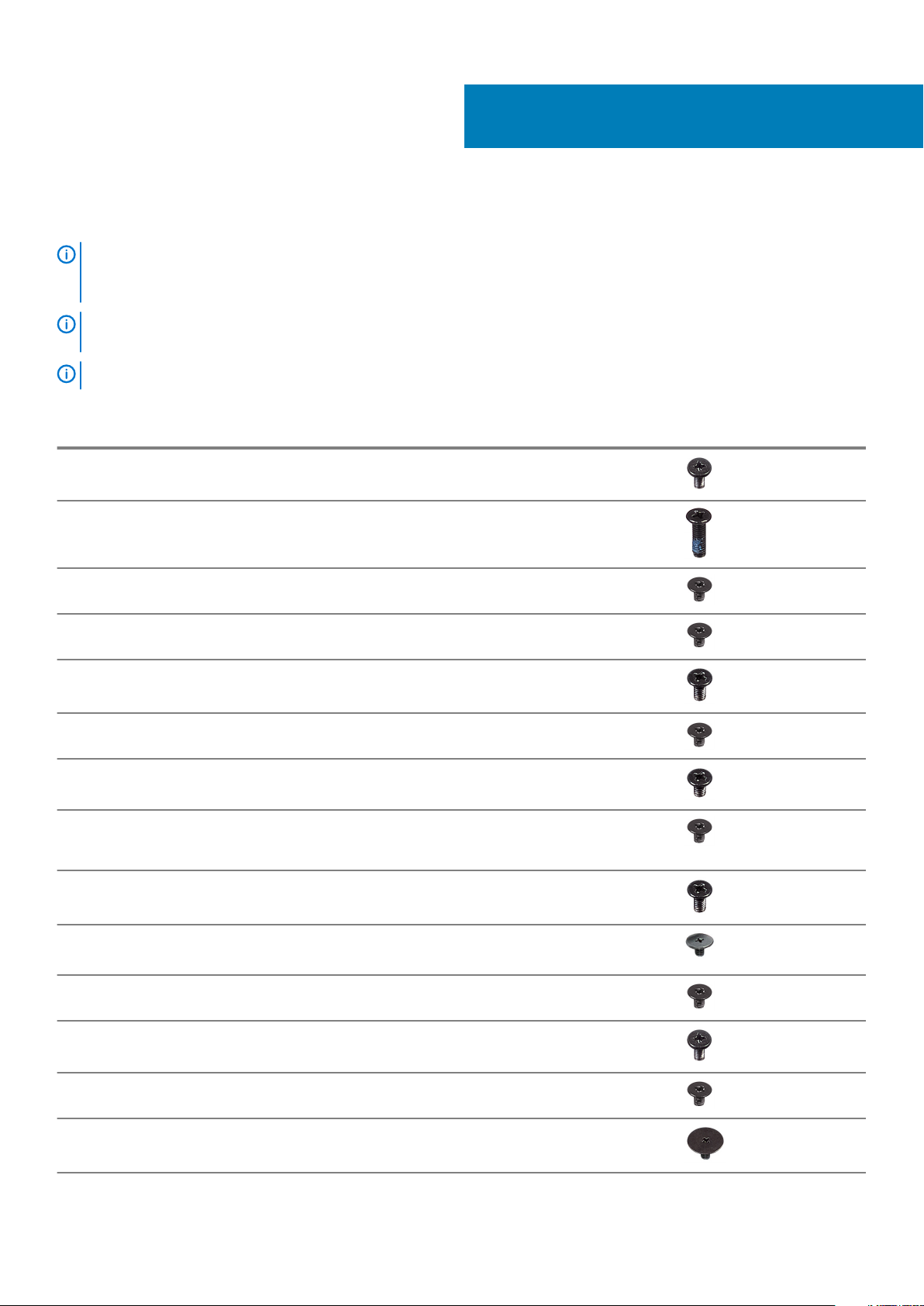
Table 1. Screw list
Component Secured to Screw type Quantity Screw image
Base cover Optical-drive assembly M2x4 2
5
Base cover Palm rest and keyboard
assembly
Battery Palm rest and keyboard
assembly
Display panel Display back-cover and
antenna assembly
Fan Palm rest and keyboard
assembly
Hard-drive assembly Palm rest and keyboard
assembly
Hard-drive bracket Hard drive M3x3 4
Heat sink (for computers
shipped with discrete
graphics)
Hinges Palm rest and keyboard
Hinge brackets Display back-cover and
System board M2x3 3
assembly
antenna assembly
M2.5x7 6
M2x3 4
M2x3 4
M2.5x5 3
M2x3 4
M2.5x5 5
M2.5x4 8
Hinge brackets Display back-cover and
antenna assembly
I/O board Palm rest and keyboard
assembly
Optical-drive bracket Optical drive M2x3 2
Optical-drive connector
board
Palm rest and keyboard
assembly
M2x3 2
M2x4 1
M2x2 Big Head 1
Screw list 15
Page 16
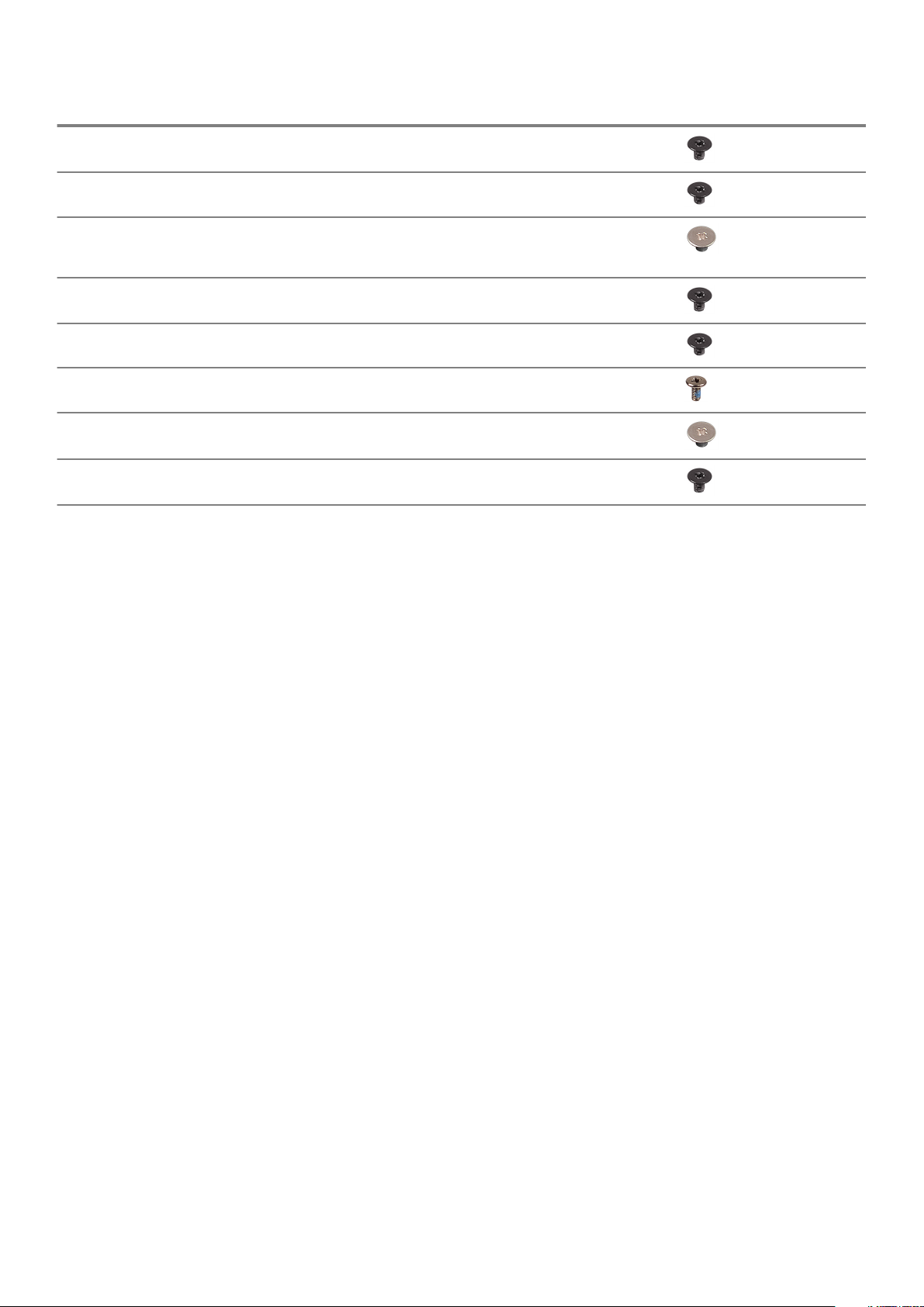
Component Secured to Screw type Quantity Screw image
Power-adapter port Palm rest and keyboard
assembly
Power-button board Palm rest and keyboard
assembly
Power button with
fingerprint reader
(optional)
M.2 2230/2280 thermal
shield
M.2 2230 solid-state drive M.2 2230 thermal shield M2x2.2 1
System board Palm rest and keyboard
Touchpad Palm rest and keyboard
Wireless-card bracket System board M2x3 1
Palm rest and keyboard
assembly
Palm rest and keyboard
assembly
assembly
assembly
M2x3 1
M2x2 1
M2x2 1
M2x3 1
M2x4 1
M2x2 4
16 Screw list
Page 17
Removing the optical drive
NOTE: Before working inside your computer, read the safety information that shipped with your computer and follow
the steps in Before working inside your computer. After working inside your computer, follow the instructions in After
working inside your computer. For more safety best practices, see the Regulatory Compliance home page at
www.dell.com/regulatory_compliance.
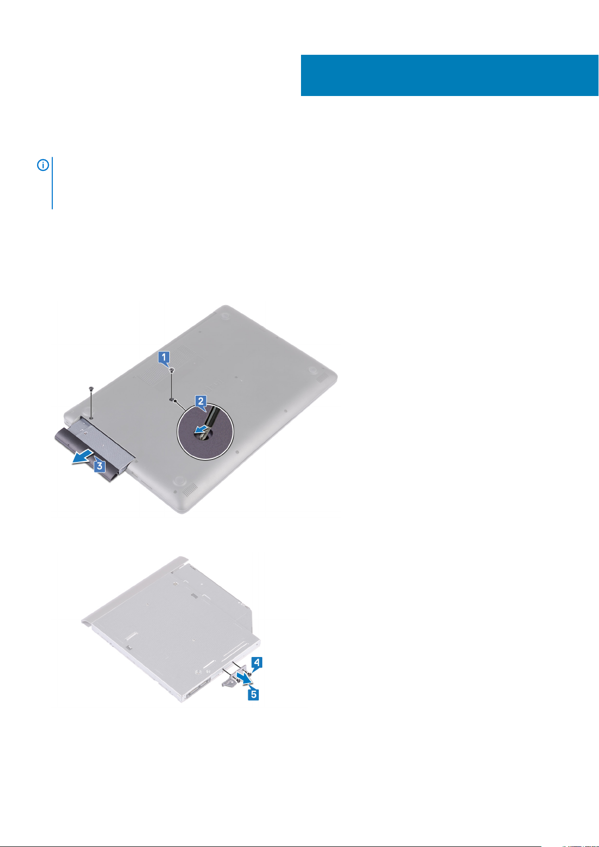
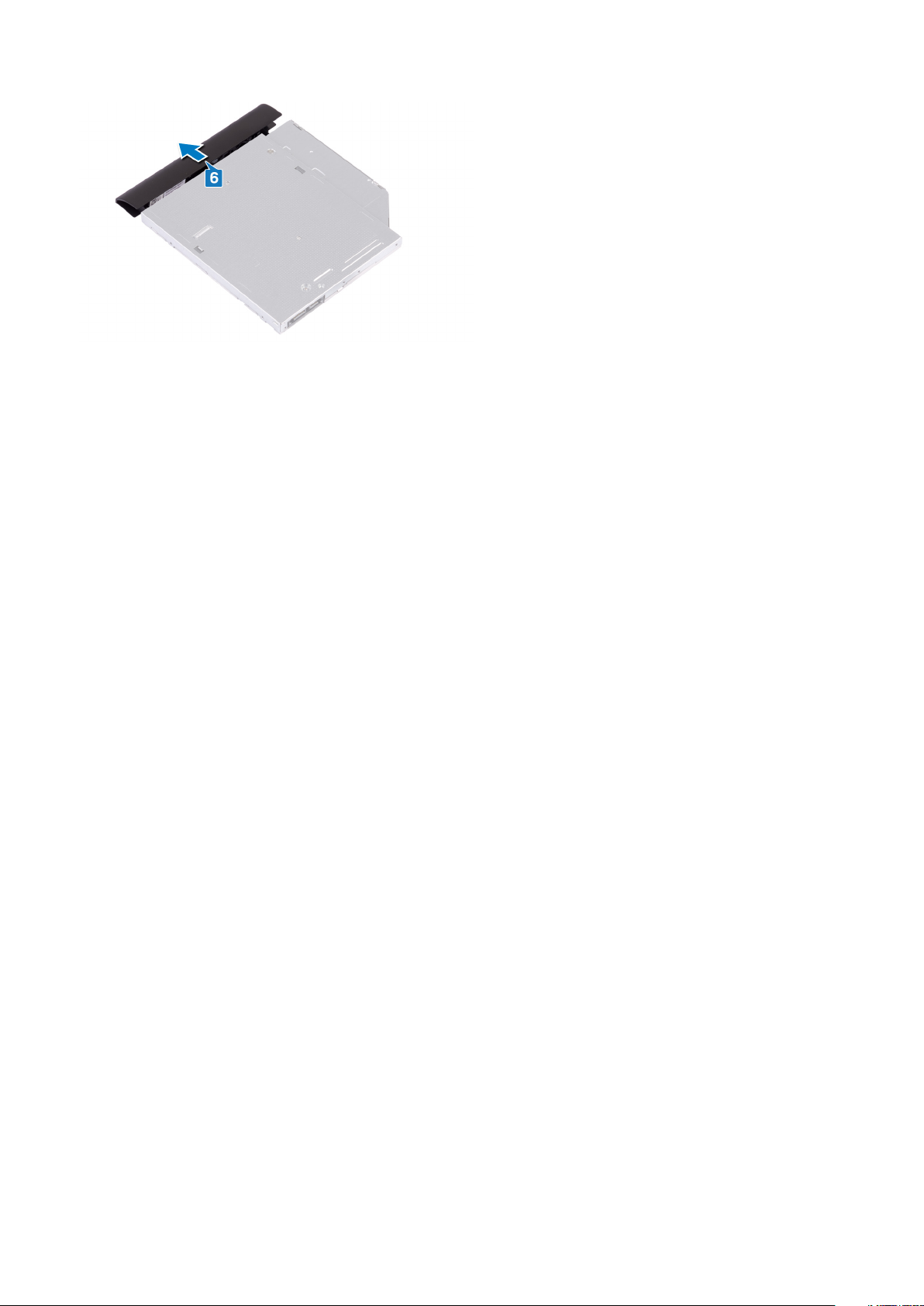
Procedure
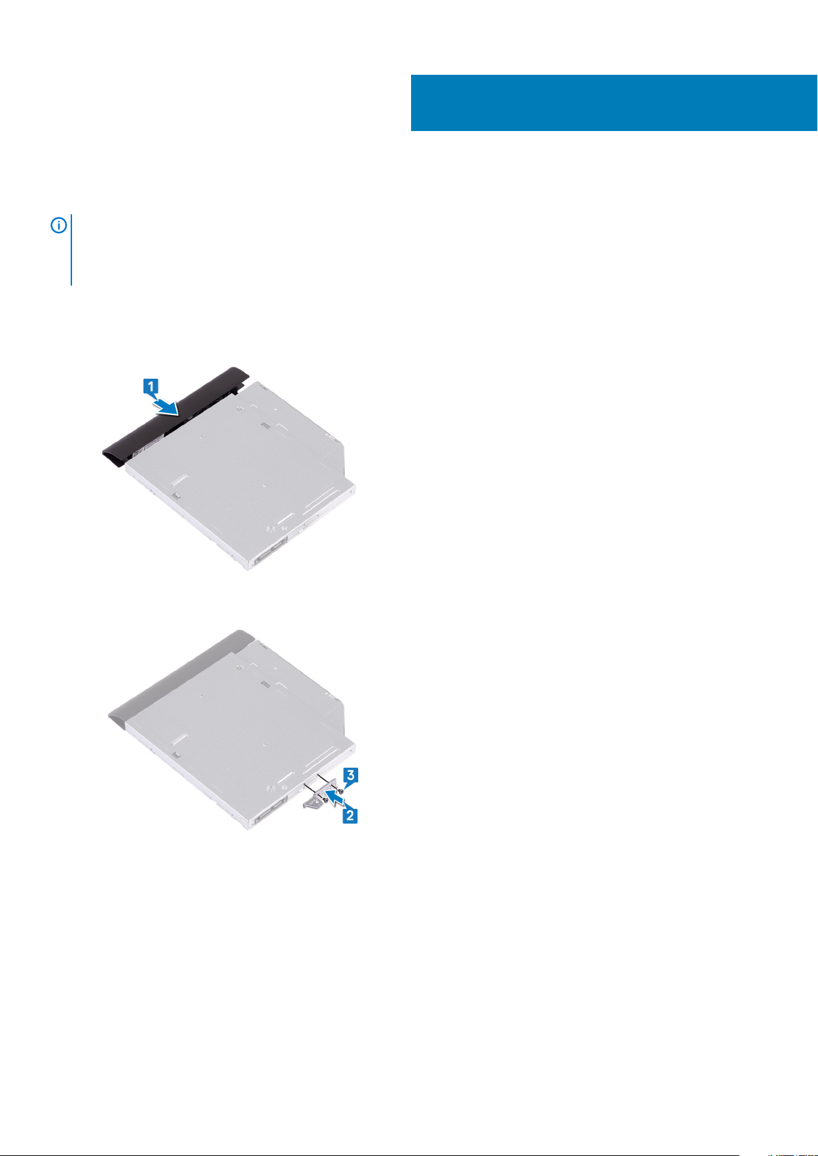
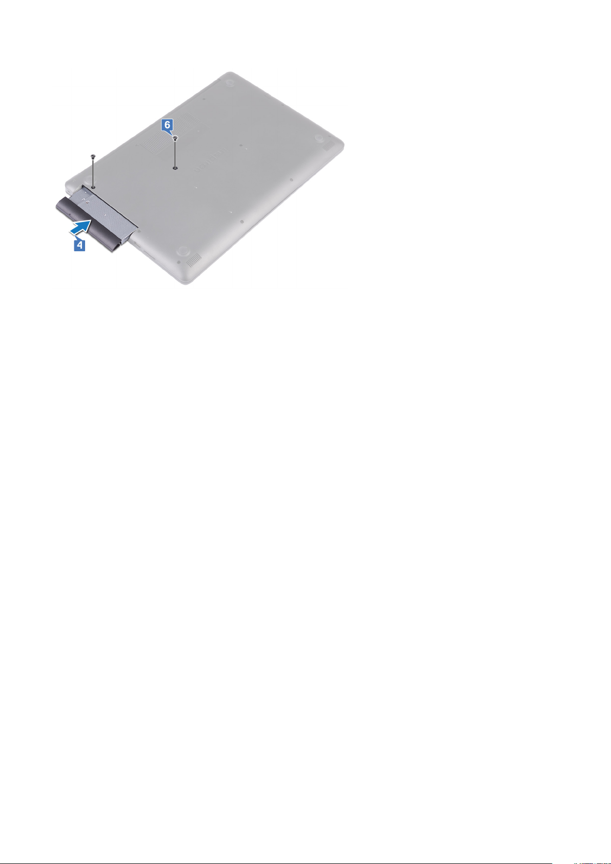
1. Remove the two screws (M2x4) that secure the optical-drive assembly to the base cover.
2. Using a screwdriver, push the optical drive through the slot to release the optical-drive assembly out of the optical-drive bay.
3. Slide the optical-drive assembly out of the optical-drive bay.
6
4. Remove the two screws (M2x3) that secure the optical-drive bracket to the optical drive.
5. Remove the optical-drive bracket from optical drive.
6. Pull the optical-drive bezel carefully to remove it from the optical drive.
Removing the optical drive 17
Page 18
18 Removing the optical drive
Page 19
Replacing the optical drive
NOTE: Before working inside your computer, read the safety information that shipped with your computer and follow
the steps in Before working inside your computer. After working inside your computer, follow the instructions in After
working inside your computer. For more safety best practices, see the Regulatory Compliance home page at
www.dell.com/regulatory_compliance.
Procedure
1. Align the tabs on the optical-drive bezel with the slots on the optical drive and snap the optical-drive bezel into place.
7
2. Align the screw holes on the optical-drive bracket with the screw holes on the optical drive.
3. Replace the two screws (M2x3) that secure the optical-drive bracket to the optical drive.
4. Slide the optical-drive assembly into the optical-drive bay.
5. Align the screw hole on the optical-drive bracket with the screw hole on the base cover.
6. Replace the two screws (M2x4) that secure the optical-drive assembly to the base cover.
Replacing the optical drive 19
Page 20
20 Replacing the optical drive
Page 21
Removing the base cover
NOTE: Before working inside your computer, read the safety information that shipped with your computer and follow
the steps in Before working inside your computer. After working inside your computer, follow the instructions in After
working inside your computer. For more safety best practices, see the Regulatory Compliance home page at
www.dell.com/regulatory_compliance.
Prerequisites
Remove the optical drive.
Procedure
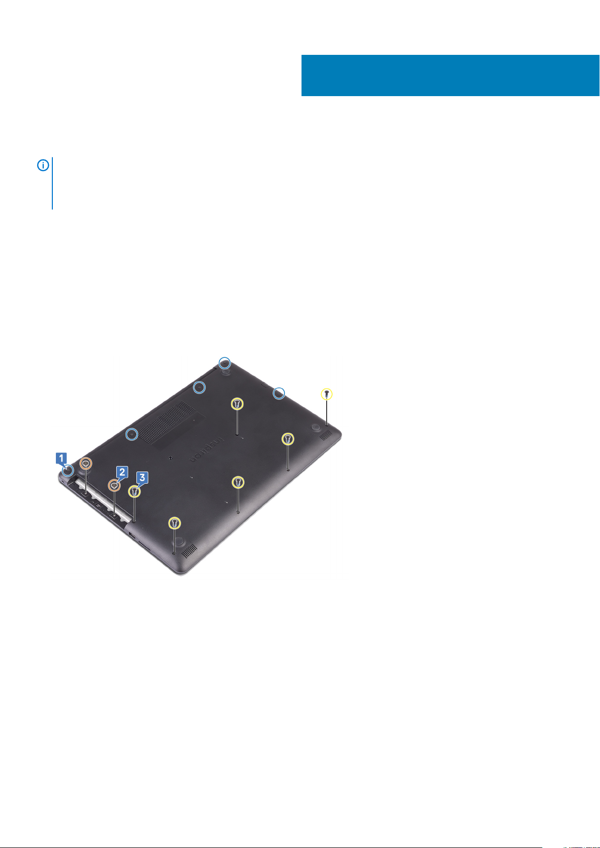
1. Loosen the five captive screws on the base cover.
2. Remove the two screws (M2x2) that secure the base cover to the palm rest and keyboard assembly.
3. Remove the six screws (M2.5x7) that secure the base cover to the palm rest and keyboard assembly.
8
4. Pry the base cover starting from the top-left corner of the computer base.
5. Lift the base cover off the palm rest and keyboard assembly.
Removing the base cover 21
Page 22
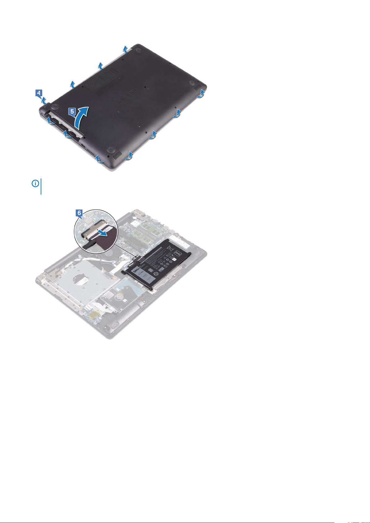
NOTE: The following steps are applicable only if you want to further remove any other component from your
computer.
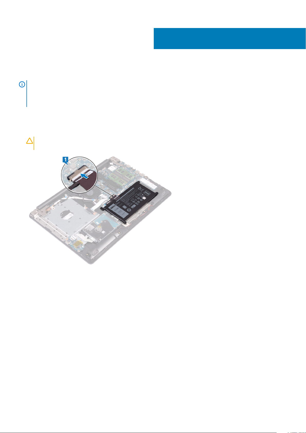
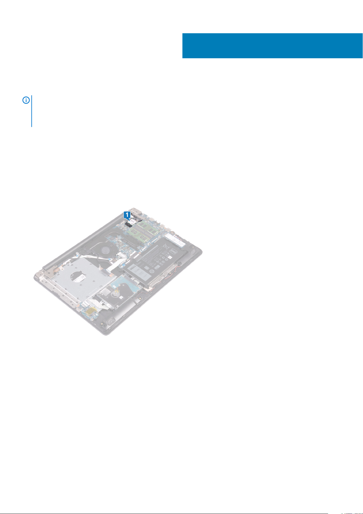
6. Disconnect the battery cable from the system board.
7. Press and hold the power button for 5 seconds to ground the computer and drain the flea power.
22
Removing the base cover
Page 23
Replacing the base cover
NOTE: Before working inside your computer, read the safety information that shipped with your computer and follow
the steps in Before working inside your computer. After working inside your computer, follow the instructions in After
working inside your computer. For more safety best practices, see the Regulatory Compliance home page at
www.dell.com/regulatory_compliance.
Procedure
1. Connect the battery cable to the system board, if applicable.
CAUTION: To avoid accidental damage to the power-adapter port, do not press the base cover against the power-
adapter port when you snap the base cover to the computer base.
9
2. Place the base cover on the palm rest and keyboard assembly, and snap the base cover into place starting from the power-adapter
port.
Replacing the base cover 23
Page 24
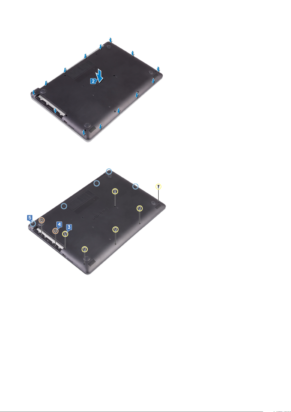
3. Replace the six screws (M2.5x7) that secure the base cover to the palm rest and keyboard assembly.
4. Replace the two screws (M2x2) that secure the base cover to the palm rest and keyboard assembly.
5. Tighten the five captive screws that secure the base cover to the palm rest and keyboard assembly.
Post-requisites
Replace the optical drive.
24
Replacing the base cover
Page 25

Removing the battery
NOTE: Before working inside your computer, read the safety information that shipped with your computer and follow
the steps in Before working inside your computer. After working inside your computer, follow the instructions in After
working inside your computer. For more safety best practices, see the Regulatory Compliance home page at
www.dell.com/regulatory_compliance.
Lithium-ion battery precautions
CAUTION:
• Exercise caution when handling Lithium-ion batteries.
• Discharge the battery as much as possible before removing it from the system. This can be done by disconnecting
the AC adapter from the system to allow the battery to drain.
• Do not crush, drop, mutilate, or penetrate the battery with foreign objects.
• Do not expose the battery to high temperatures, or disassemble battery packs and cells.
• Do not apply pressure to the surface of the battery.
• Do not bend the battery.
• Do not use tools of any kind to pry on or against the battery.
• Ensure any screws during the servicing of this product are not lost or misplaced, to prevent accidental puncture or
damage to the battery and other system components.
• If a battery gets stuck in a device as a result of swelling, do not try to free it as puncturing, bending, or crushing a
Lithium-ion battery can be dangerous. In such an instance, contact for assistance and further instructions.
• If the battery gets stuck inside your computer as a result of swelling, do not try to release it as puncturing, bending,
or crushing a lithium-ion battery can be dangerous. In such an instance, contact Dell technical support for
assistance. See www.dell.com/contactdell.
• Always purchase genuine batteries from www.dell.com or authorized Dell partners and resellers.
10
Prerequisites
1. Remove the optical drive.
2. Remove the base cover.
Procedure
NOTE:
procedure.
1. Remove the four screws (M2x3) that secure the battery to the palm rest and keyboard assembly.
2. Lift the battery off the palm rest and keyboard assembly.
Ensure that the battery cable has been disconnected from the system board before performing the following
Removing the battery 25
Page 26

26 Removing the battery
Page 27

Replacing the battery
NOTE: Before working inside your computer, read the safety information that shipped with your computer and follow
the steps in Before working inside your computer. After working inside your computer, follow the instructions in After
working inside your computer. For more safety best practices, see the Regulatory Compliance home page at
www.dell.com/regulatory_compliance.
Lithium-ion battery precautions
CAUTION:
• Exercise caution when handling Lithium-ion batteries.
• Discharge the battery as much as possible before removing it from the system. This can be done by disconnecting
the AC adapter from the system to allow the battery to drain.
• Do not crush, drop, mutilate, or penetrate the battery with foreign objects.
• Do not expose the battery to high temperatures, or disassemble battery packs and cells.
• Do not apply pressure to the surface of the battery.
• Do not bend the battery.
• Do not use tools of any kind to pry on or against the battery.
• Ensure any screws during the servicing of this product are not lost or misplaced, to prevent accidental puncture or
damage to the battery and other system components.
• If a battery gets stuck in a device as a result of swelling, do not try to free it as puncturing, bending, or crushing a
Lithium-ion battery can be dangerous. In such an instance, contact for assistance and further instructions.
• If the battery gets stuck inside your computer as a result of swelling, do not try to release it as puncturing, bending,
or crushing a lithium-ion battery can be dangerous. In such an instance, contact Dell technical support for
assistance. See www.dell.com/contactdell.
• Always purchase genuine batteries from www.dell.com or authorized Dell partners and resellers.
11
Procedure
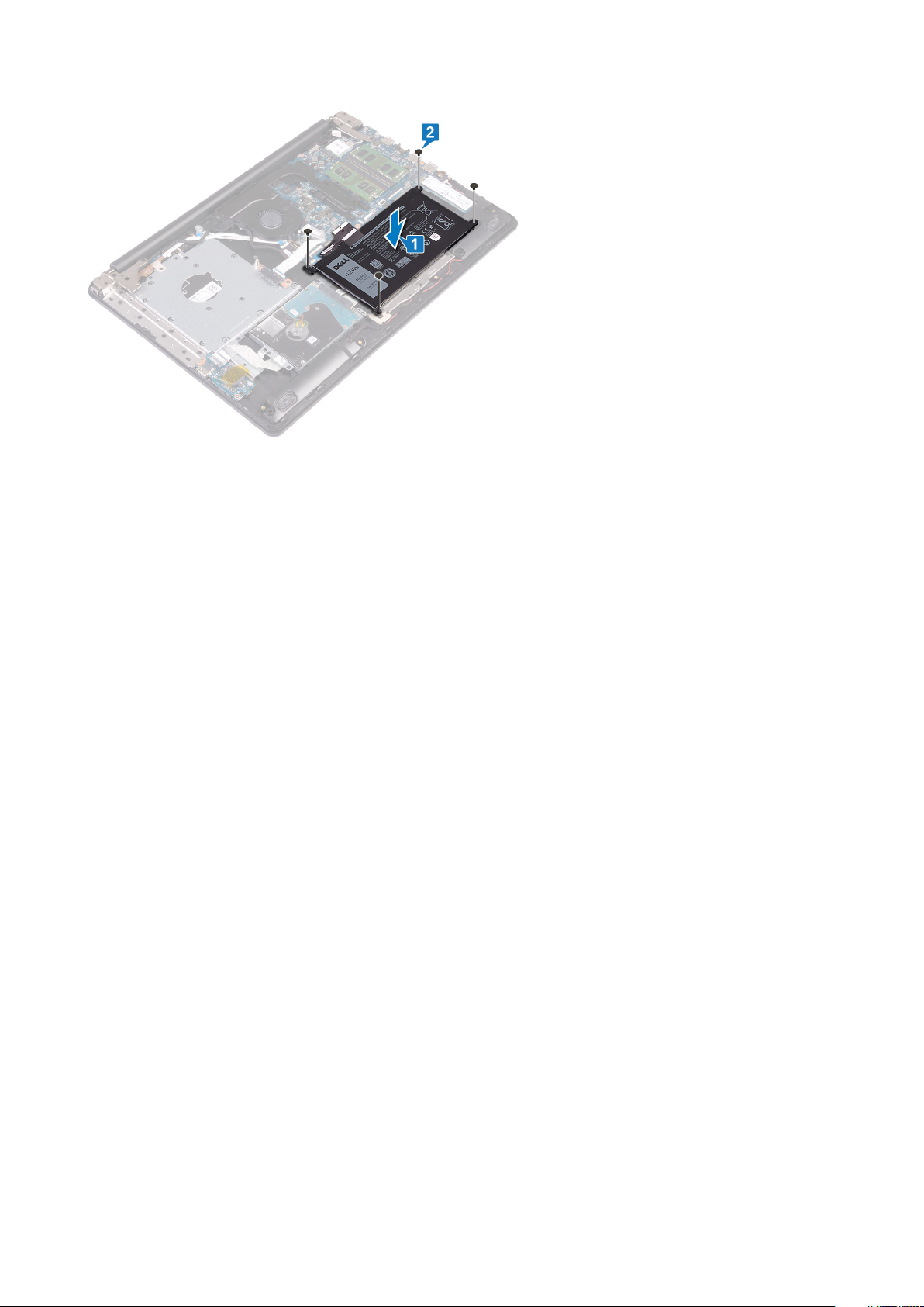
1. Align the screw holes on the battery with the screw holes on the palm rest and keyboard assembly.
2. Replace the four screws (M2x3) that secure the battery to the palm rest and keyboard assembly.
Replacing the battery 27
Page 28
Post-requisites
1. Replace the base cover.
2. Replace the optical drive.
28
Replacing the battery
Page 29
Removing the memory modules
NOTE: Before working inside your computer, read the safety information that shipped with your computer and follow
the steps in Before working inside your computer. After working inside your computer, follow the instructions in After
working inside your computer. For more safety best practices, see the Regulatory Compliance home page at
www.dell.com/regulatory_compliance.
Prerequisites
1. Remove the optical drive.
2. Remove the base cover.
Procedure
NOTE: Depending on the configuration ordered, your computer may have up to two memory modules installed. Repeat
the following procedure twice if you are removing both memory modules.
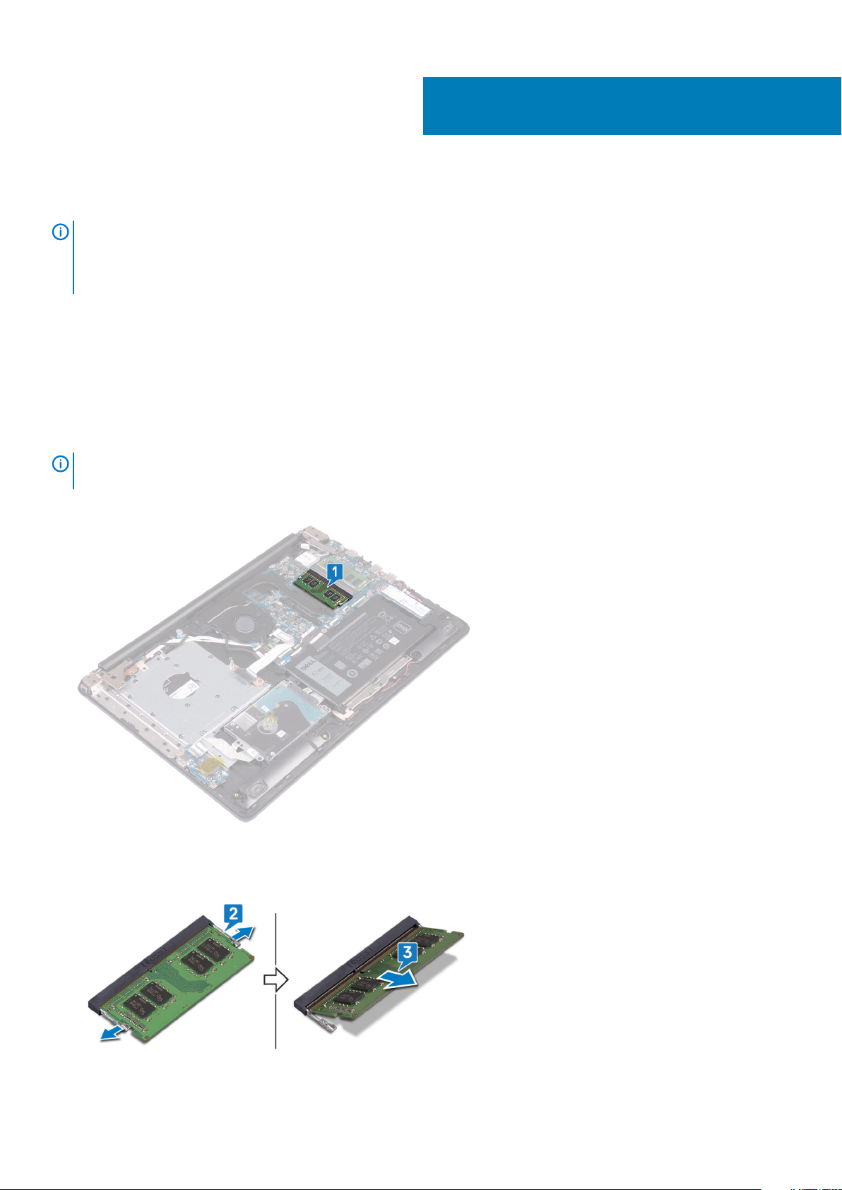
1. Locate the memory module on your computer.
12
2. Use your fingertips to carefully spread apart the securing-clips on each end of the memory-module slot until the memory module pops
up.
3. Remove the memory module from the memory-module slot.
Removing the memory modules 29
Page 30
Replacing the memory modules
NOTE: Before working inside your computer, read the safety information that shipped with your computer and follow
the steps in Before working inside your computer. After working inside your computer, follow the instructions in After
working inside your computer. For more safety best practices, see the Regulatory Compliance home page at
www.dell.com/regulatory_compliance.
Procedure
NOTE: This computer can support up to two memory modules. Repeat the following procedure twice if you are installing
two memory modules.
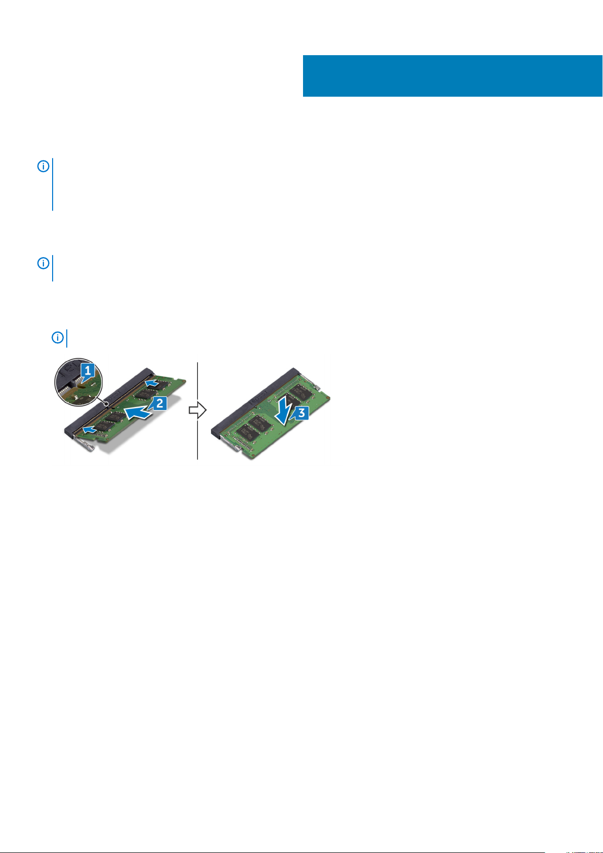
1. Align the notch on the memory module with the tab on the memory-module slot.
2. Slide the memory module firmly into the slot at an angle.
3. Press the memory module down until it clicks into place.
13
NOTE:
If you do not hear the click, remove the memory module and reinstall it.
Post-requisites
1. Replace the base cover.
2. Replace the optical drive.
30 Replacing the memory modules
Page 31
Removing the wireless card
NOTE: Before working inside your computer, read the safety information that shipped with your computer and follow
the steps in Before working inside your computer. After working inside your computer, follow the instructions in After
working inside your computer. For more safety best practices, see the Regulatory Compliance home page at
www.dell.com/regulatory_compliance.
Prerequisites
1. Remove the optical drive.
2. Remove the base cover.
Procedure
1. Locate the wireless card on your computer.
14
2. Remove the screw (M2x3) that secures the wireless-card bracket to the system board.
3. Slide and remove the wireless-card bracket from the wireless card.
4. Using a plastic scribe, disconnect the antenna cables from the wireless card.
5. Slide and remove the wireless card from the wireless-card slot.
Removing the wireless card 31
Page 32

32 Removing the wireless card
Page 33

Replacing the wireless card
NOTE: Before working inside your computer, read the safety information that shipped with your computer and follow
the steps in Before working inside your computer. After working inside your computer, follow the instructions in After
working inside your computer. For more safety best practices, see the Regulatory Compliance home page at
www.dell.com/regulatory_compliance.
Procedure
15
CAUTION:
1. Connect the antenna cables to the wireless card.
The following table provides the antenna-cable color scheme for the wireless card supported by your computer.
Table 2. Antenna-cable color scheme
Connectors on the wireless card Antenna-cable color
Main (white triangle) White
Auxiliary (black triangle) Black
2. Slide and replace the wireless-card bracket on the wireless-card.
3. Align the notch on the wireless card with the tab on the wireless-card slot and insert the wireless card at an angle into the wirelesscard slot.
4. Replace the screw (M2x3) that secures the wireless-card bracket to the wireless card and the palm rest and keyboard assembly.
To avoid damage to the wireless card, do not place any cables under it.
Post-requisites
1. Replace the base cover.
2. Replace the optical drive.
Replacing the wireless card 33
Page 34

Removing the optical-drive connector board
NOTE: Before working inside your computer, read the safety information that shipped with your computer and follow
the steps in Before working inside your computer. After working inside your computer, follow the instructions in After
working inside your computer. For more safety best practices, see the Regulatory Compliance home page at
www.dell.com/regulatory_compliance.
Prerequisites
1. Remove the optical drive.
2. Remove the base cover.
Procedure
16
NOTE:
1. Lift the latch and disconnect the optical-drive connector-board cable from the system board.
2. Remove the two screws (M2x2) that secure the optical-drive connector board to the palm rest and keyboard assembly.
3. Lift the optical-drive connector board along with the cable off the palm rest and keyboard assembly.
Applicable only for computers that are shipped with optical drive.
34 Removing the optical-drive connector board
Page 35

Replacing the optical-drive connector board
NOTE: Before working inside your computer, read the safety information that shipped with your computer and follow
the steps in Before working inside your computer. After working inside your computer, follow the instructions in After
working inside your computer. For more safety best practices, see the Regulatory Compliance home page at
www.dell.com/regulatory_compliance.
Procedure
1. Align the screw hole on the optical-drive connector board with the screw hole on the palm rest and keyboard assembly.
2. Replace the two screws (M2x2) that secure the optical-drive connector board to the palm rest and keyboard assembly.
3. Connect the optical-drive connector-board cable to the system board.
4. Close the latch that secures the optical-drive connector-board cable to the system board.
17
Post-requisites
1. Replace the base cover.
2. Replace the optical drive.
Replacing the optical-drive connector board 35
Page 36

Removing the coin-cell battery
NOTE: Before working inside your computer, read the safety information that shipped with your computer and follow
the steps in Before working inside your computer. After working inside your computer, follow the instructions in After
working inside your computer. For more safety best practices, see the Regulatory Compliance home page at
www.dell.com/regulatory_compliance.
CAUTION: Removing the coin-cell battery resets the BIOS setup program’s settings to default. It is recommended that
you note the BIOS setup program’s settings before removing the coin-cell battery.
Prerequisites
1. Remove the optical drive.
2. Remove the base cover.
Procedure
18
CAUTION:
coin-cell battery, it is recommended to note the BIOS setup program’s settings.
1. If available, peel off the tape that secures the coin-cell battery to the I/O board.
2. Using a plastic scribe, gently pry the coin-cell battery out of the battery socket on the I/O board.
Removing the coin-cell battery resets the BIOS setup program’s settings to default. Before removing the
36 Removing the coin-cell battery
Page 37

Replacing the coin-cell battery
NOTE: Before working inside your computer, read the safety information that shipped with your computer and follow
the steps in Before working inside your computer. After working inside your computer, follow the instructions in After
working inside your computer. For more safety best practices, see the Regulatory Compliance home page at
www.dell.com/regulatory_compliance.
Procedure
1. With the positive-side facing up, snap the coin-cell battery into the battery socket on the I/O board.
2. If available, adhere the tape that secures the coin-cell battery to the I/O board.
19
Post-requisites
1. Replace the base cover.
2. Replace the optical drive.
Replacing the coin-cell battery 37
Page 38

Removing the fan
NOTE: Before working inside your computer, read the safety information that shipped with your computer and follow
the steps in Before working inside your computer. After working inside your computer, follow the instructions in After
working inside your computer. For more safety best practices, see the Regulatory Compliance home page at
www.dell.com/regulatory_compliance.
Prerequisites
1. Remove the optical drive.
2. Remove the base cover.
Procedure
1. Lift the latch and disconnect the optical-drive connector-board cable from the system board.
2. Lift the latch and disconnect the optical-drive connector-board cable from the optical-drive board connector.
3. Lift the optical-drive connector-board cable off the system board.
4. Open the latch and disconnect the display cable from the system board.
5. Remove the display cable from the routing guides on the fan.
20
6. Disconnect the fan cable from the system board.
7. Remove the three screws (M2.5x5) that secure the fan to the palm rest and keyboard board assembly.
8. Lift the fan off the palm rest and keyboard board assembly.
38 Removing the fan
Page 39

Removing the fan 39
Page 40

Replacing the fan
NOTE: Before working inside your computer, read the safety information that shipped with your computer and follow
the steps in Before working inside your computer. After working inside your computer, follow the instructions in After
working inside your computer. For more safety best practices, see the Regulatory Compliance home page at
www.dell.com/regulatory_compliance.
Procedure
1. Align the screw holes on the fan with the screw holes on to the palm rest and keyboard board assembly.
2. Replace the three screws (M2.5x5) that secure the fan to the palm rest and keyboard board assembly.
3. Connect the fan cable to the system board.
21
4. Route the display cable through the routing guides on the fan.
5. Connect the display cable to its connector on system board and close the latch to secure the cable.
6. Press down on the latch to connect the optical-drive connector-board cable to the optical-drive connector board.
7. Press down on the latch to connect the optical-drive connector-board cable to the system board.
40 Replacing the fan
Page 41

Post-requisites
1. Replace the base cover.
2. Replace the optical drive.
Replacing the fan
41
Page 42
22
Removing the solid-state drive/Intel Optane
You need to disable the Intel Optane device before removing it from your computer. For more information about disabling the Intel Optane
device, see Disabling Intel Optane memory.
NOTE: Before working inside your computer, read the safety information that shipped with your computer and follow
the steps in Before working inside your computer. After working inside your computer, follow the instructions in After
working inside your computer. For more safety best practices, see the Regulatory Compliance home page at
www.dell.com/regulatory_compliance.
Prerequisites
1. Remove the optical drive.
2. Remove the base cover.
Procedure to remove the M.2 2230 solid-state drive
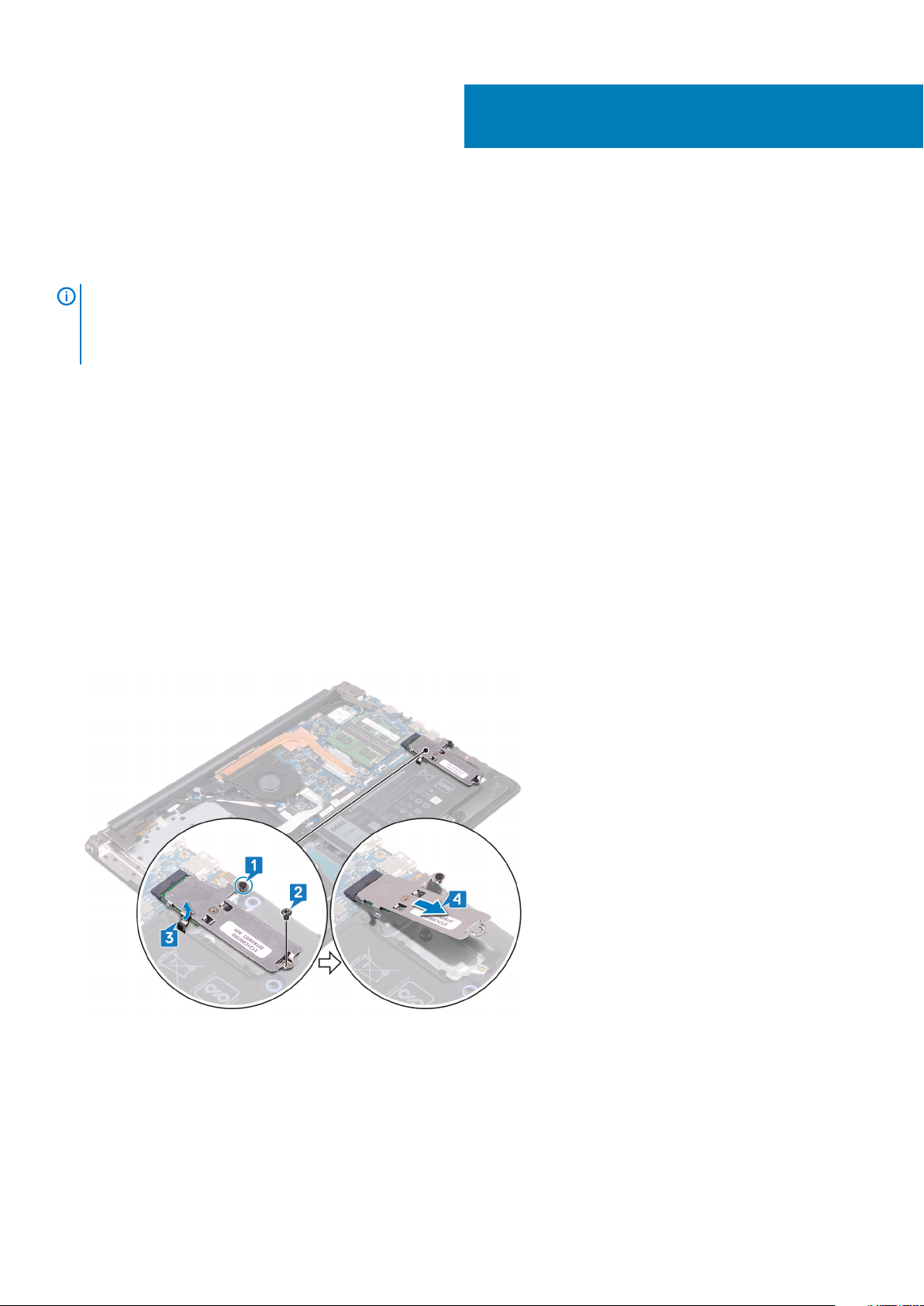
1. Loosen the captive screw that secures the M.2 2230 thermal shield to the palm-rest and keyboard assembly.
2. Remove the screw (M2x3) that secures the M.2 2230 thermal shield to the palm-rest and keyboard assembly.
3. Slide and remove the tab on the M.2 2230 thermal shield from the slot on the palm-rest and keyboard assembly.
4. Lift the solid-state drive and M.2 2230 thermal shield at an angle and remove it from the M.2 slot on the system board.
5. Turn the M.2 2230 thermal shield over.
6. Remove the screw (M2x2) that secures the solid-state drive to the M.2 2230 thermal shield.
7. Lift the solid-state drive off the M.2 2230 thermal shield.
42 Removing the solid-state drive/Intel Optane
Page 43
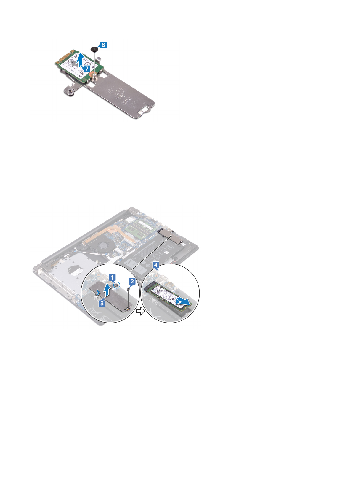
Procedure to remove the M.2 2280 solid-state drive/Intel Optane
1. Loosen the captive screw that secures the M.2 2280 thermal shield to the palm-rest and keyboard assembly.
2. Remove the screw (M2x3) that secures the M.2 2280 thermal shield and solid-state drive/Intel Optane to the palm-rest and keyboard
assembly.
3. Slide and remove the tab on the M.2 2280 thermal shield from the slot on the palm-rest and keyboard assembly .
4. Lift the solid-state drive/Intel Optane at an angle and remove it from the M.2 slot on the system board.
Removing the solid-state drive/Intel Optane
43
Page 44

23
Replacing the solid-state drive/Intel Optane
Enable the Intel Optane device after you replace it. For more information about enabling the Intel Optane device, see Enabling Intel Optane
memory.
NOTE: Before working inside your computer, read the safety information that shipped with your computer and follow
the steps in Before working inside your computer. After working inside your computer, follow the instructions in After
working inside your computer. For more safety best practices, see the Regulatory Compliance home page at
www.dell.com/regulatory_compliance.
CAUTION: Solid-state drives are fragile. Exercise care when handling the solid-state drive.
Procedure to replace the M.2 2230 solid-state drive
1. Place the solid-state drive into the slot on the back of the M.2 2230 thermal shield.
2. Replace the screw (M2x2) that secures the solid-state drive to the M.2 2230 thermal shield.
3. Turn over the M.2 2230 thermal shield.
4. Align the notch on the solid-state drive with the tab on the M.2 slot and slide the solid-state drive into the M.2 slot on the system
board.
5. Insert the tab of the M.2 2230 thermal shield into the slot on the palm-rest and keyboard assembly.
6. Tighten the captive screw that secures the M.2 2230 thermal shield to the palm-rest and keyboard assembly.
7. Replace the screw (M2x3) that secures the M.2 2230 thermal shield to the palm-rest and keyboard assembly.
44 Replacing the solid-state drive/Intel Optane
Page 45

Procedure to replace the M.2 2280 solid-state drive/Intel Optane
1. Align the notch on the solid-state drive/Intel Optane with the tab on the M.2 slot and slide the solid-state drive/Intel Optane into the
M.2 slot on the system board.
2. Insert the tab of the M.2 2280 thermal shield into the slot on the palm-rest and keyboard assembly.
3. Tighten the captive screw that secures the M.2 2280 thermal shield to the palm-rest and keyboard assembly.
4. Replace the screw (M2x3) that secures the M.2 2280 thermal shield and solid-state drive/Intel Optane to the palm-rest and keyboard
assembly.
]
Post-requisites
1. Replace the base cover.
2. Replace the optical drive.
Replacing the solid-state drive/Intel Optane
45
Page 46

24
Removing the hard drive
If your computer is using a SATA storage device accelerated by Intel Optane memory, disable Intel Optane before removing the SATA
storage device. For more information about disabling the Intel Optane, see Disabling Intel Optane.
NOTE: Before working inside your computer, read the safety information that shipped with your computer and follow
the steps in Before working inside your computer. After working inside your computer, follow the instructions in After
working inside your computer. For more safety best practices, see the Regulatory Compliance home page at
www.dell.com/regulatory_compliance.
CAUTION: Hard drives are fragile. Exercise care when handling the hard drive.
CAUTION: To avoid data loss, do not remove the hard drive while the computer is in sleep or on state.
Prerequisites
1. Remove the optical drive.
2. Remove the base cover.
3. Remove the battery.
Procedure
1. Open the latch and disconnect the hard-drive cable from the system board.
2. Remove the four screws (M2x3) that secure the hard-drive assembly to the palm rest and keyboard assembly.
3. Lift the hard-drive assembly along with its cable off the palm rest and keyboard assembly.
4. Disconnect the interposer from the hard-drive assembly.
46 Removing the hard drive
Page 47

5. Remove the four screws (M3x3) that secure the hard-drive bracket to the hard drive.
6. Lift the hard-drive bracket off the hard drive.
Removing the hard drive 47
Page 48

25
Replacing the hard drive
Enable Intel Optane after replacing the SATA storage. For more information about enabling the Intel Optane, see Enabling Intel Optane.
NOTE: Before working inside your computer, read the safety information that shipped with your computer and follow
the steps in Before working inside your computer. After working inside your computer, follow the instructions in After
working inside your computer. For more safety best practices, see the Regulatory Compliance home page at
www.dell.com/regulatory_compliance.
CAUTION: Hard drives are fragile. Exercise care when handling the hard drive.
Procedure
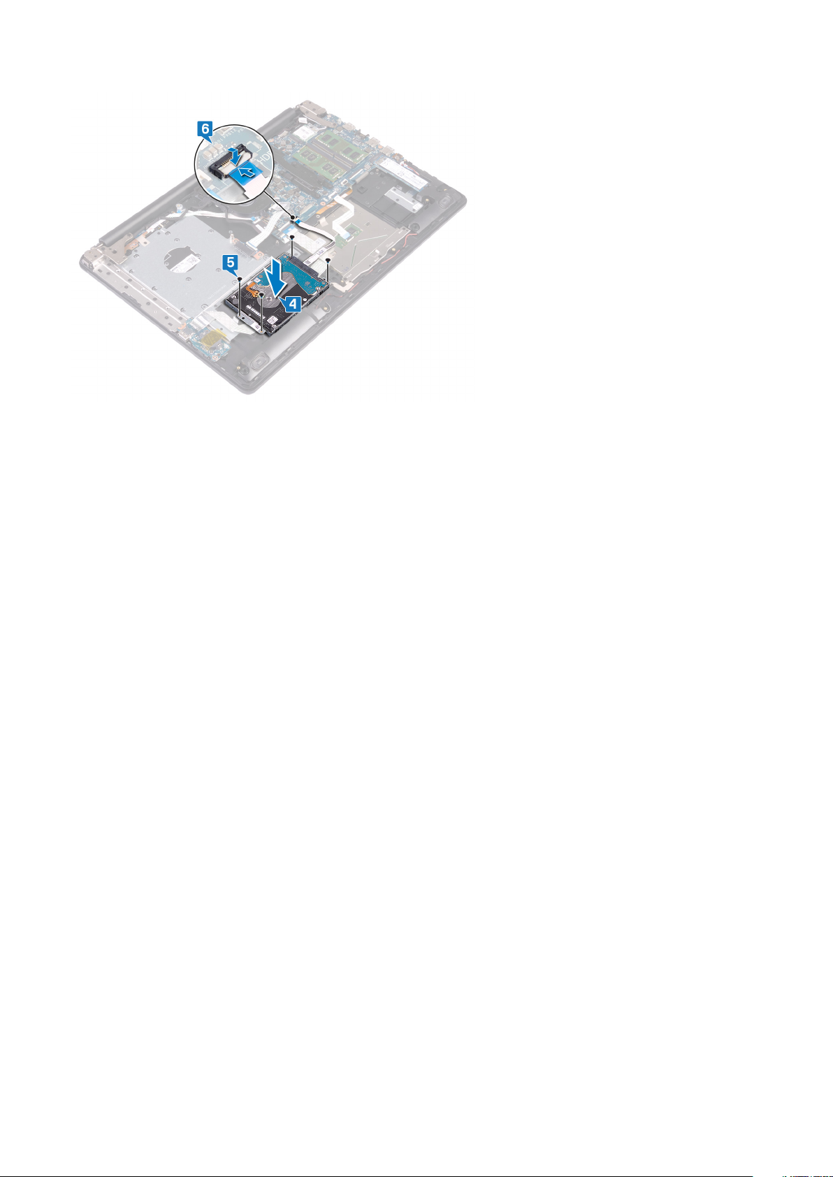
1. Align the screw holes on the hard-drive bracket with the screw holes on the hard drive.
2. Replace the four screws (M3x3) that secure the hard-drive bracket to the hard drive.
3. Connect the interposer to the hard-drive assembly.
4. Align the screw holes on the hard-drive assembly with the screw holes on the palm rest and keyboard assembly.
5. Replace the four screws (M2x3) that secure the hard-drive assembly to the palm rest and keyboard assembly.
6. Connect the hard-drive cable to the system board and close the latch to secure the cable.
48 Replacing the hard drive
Page 49
Post-requisites
1. Replace the battery.
2. Replace the base cover.
3. Replace the optical drive.
Replacing the hard drive
49
Page 50

Removing the touchpad
NOTE: Before working inside your computer, read the safety information that shipped with your computer and follow
the steps in Before working inside your computer. After working inside your computer, follow the instructions in After
working inside your computer. For more safety best practices, see the Regulatory Compliance home page at
www.dell.com/regulatory_compliance.
Prerequisites
1. Remove the optical drive.
2. Remove the base cover.
3. Remove the battery.
Procedure
1. Open the latch and disconnect the I/O-board cable from the system board.
2. Open the latch and disconnect the hard-drive cable from the system board.
3. Gently peel the tape that secures the touchpad to the palm rest and keyboard assembly.
4. Open the latch and disconnect the touchpad cable from the system board.
26
5. Remove the four screws (M2x2) that secure the touchpad to the palm rest and keyboard assembly.
6. Slide and lift the touchpad off the palm rest and keyboard assembly.
50 Removing the touchpad
Page 51

Removing the touchpad 51
Page 52

Replacing the touchpad
NOTE: Before working inside your computer, read the safety information that shipped with your computer and follow
the steps in Before working inside your computer. After working inside your computer, follow the instructions in After
working inside your computer. For more safety best practices, see the Regulatory Compliance home page at
www.dell.com/regulatory_compliance.
Procedure
NOTE: Ensure that the touchpad is aligned with the guides available on the palm-rest and keyboard assembly, and the
gap on either sides of the touchpad is equal.
1. Slide and place the touchpad into the slot on the palm rest and keyboard assembly.
2. Replace the four screws (M2x2) that secure the touchpad to the palm rest and keyboard assembly.
27
3. Adhere the tape that secures the touchpad to the palm rest and keyboard assembly.
4. Slide the touchpad cable into the touchpad connector on the system board and close the latch to secure the cable.
5. Slide the I/O-board cable into the connector on the system board and close the latch to secure the cable.
6. Slide the hard-drive cable into the hard-drive connector on the system board and close the latch to secure the cable.
52 Replacing the touchpad
Page 53
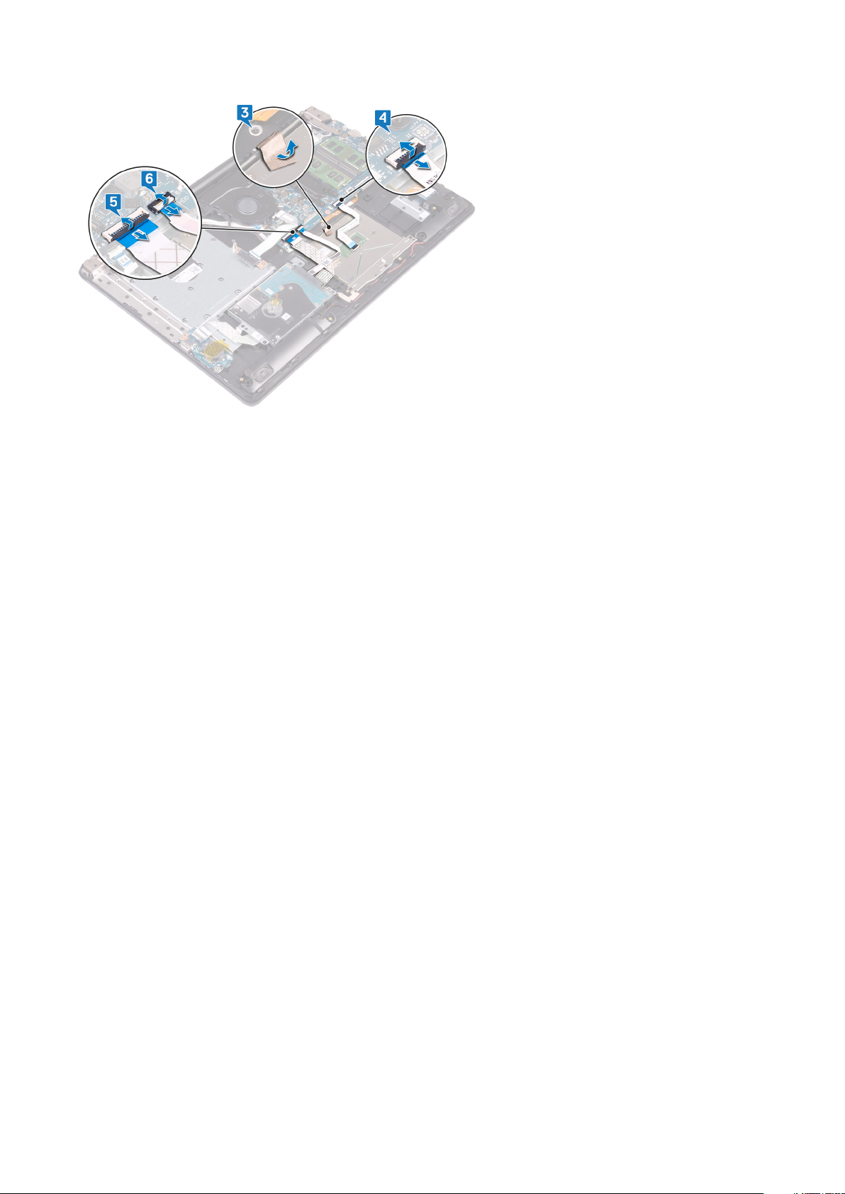
Post-requisites
1. Replace the battery.
2. Replace the base cover.
3. Replace the optical drive.
Replacing the touchpad
53
Page 54

Removing the speakers
NOTE: Before working inside your computer, read the safety information that shipped with your computer and follow
the steps in Before working inside your computer. After working inside your computer, follow the instructions in After
working inside your computer. For more safety best practices, see the Regulatory Compliance home page at
www.dell.com/regulatory_compliance.
Prerequisites
1. Remove the optical drive.
2. Remove the base cover.
3. Remove the solid-state drive/Intel Optane.
Procedure
1. Disconnect the speaker cable from the system board and lift the right speaker off the palm rest and keyboard assembly.
2. Note the speaker cable routing and remove it from the routing guides on palm rest and key board assembly.
3. Lift the left speaker, along with the cable, off the palm rest and keyboard assembly.
28
54 Removing the speakers
Page 55

Replacing the speakers
NOTE: Before working inside your computer, read the safety information that shipped with your computer and follow
the steps in Before working inside your computer. After working inside your computer, follow the instructions in After
working inside your computer. For more safety best practices, see the Regulatory Compliance home page at
www.dell.com/regulatory_compliance.
Procedure
NOTE: If the rubber grommets are pushed out when removing the speakers, push them back in before replacing the
speakers.
1. Using the alignment posts and rubber grommets, place the left speakers in the slots on the palm rest and keyboard assembly.
2. Route the speaker cable through the routing guides on the palm rest and keyboard assembly.
3. Replace the right speaker.
4. Connect the speaker cable to the system board.
29
Post-requisites
1. Replace the solid-state drive/Intel Optane.
2. Replace the base cover.
3. Replace the optical drive.
Replacing the speakers 55
Page 56

Removing the heat sink
NOTE: Before working inside your computer, read the safety information that shipped with your computer and follow
the steps in Before working inside your computer. After working inside your computer, follow the instructions in After
working inside your computer. For more safety best practices, see the Regulatory Compliance home page at
www.dell.com/regulatory_compliance.
NOTE: The heat sink may become hot during normal operation. Allow sufficient time for the heat sink to cool before you
touch it.
CAUTION: For maximum cooling of the processor, do not touch the heat transfer areas on the heat sink. The oils in your
skin can reduce the heat transfer capability of the thermal grease.
Prerequisites
1. Remove the optical drive.
2. Remove the base cover.
3. Remove the fan.
30
Procedure
1. In sequential order as indicated on the heat sink (1>2>3>4), loosen the four captive screws that secure the heat sink to the system
board.
2. Remove the three (M2x3) screws that secure the heat sink to the system board.
3. Lift the heat sink off the system board.
56 Removing the heat sink
Page 57
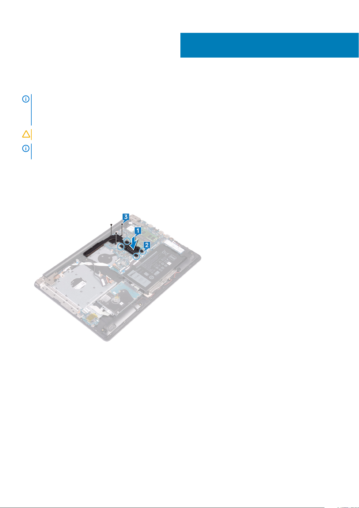
31
Replacing the heat sink
NOTE: Before working inside your computer, read the safety information that shipped with your computer and follow
the steps in Before working inside your computer. After working inside your computer, follow the instructions in After
working inside your computer. For more safety best practices, see the Regulatory Compliance home page at
www.dell.com/regulatory_compliance.
CAUTION: Incorrect alignment of the heat sink can damage the system board and processor.
NOTE: If either the system board or the heat sink is replaced, use the thermal pad/paste provided in the kit to ensure
that thermal conductivity is achieved.
Procedure
1. Place the heat sink on the system board and align the screw holes on the heat sink with the screw holes on the system board.
2. Tighten the captive screws in the reverse order as indicated on the heat sink (4>3>2>1) to secure the heat sink to the system board.
3. Replace the three (M2x3) screws that secure the heat sink to the system board.
Post-requisites
1. Replace the fan.
2. Replace the base cover.
3. Replace the optical drive.
Replacing the heat sink 57
Page 58

Removing the power-adapter port
NOTE: Before working inside your computer, read the safety information that shipped with your computer and follow
the steps in Before working inside your computer. After working inside your computer, follow the instructions in After
working inside your computer. For more safety best practices, see the Regulatory Compliance home page at
www.dell.com/regulatory_compliance.
Removing the display assembly
NOTE: Before working inside your computer, read the safety information that shipped with your computer and follow
the steps in Before working inside your computer. After working inside your computer, follow the instructions in After
working inside your computer. For more safety best practices, see the Regulatory Compliance home page at
www.dell.com/regulatory_compliance.
Prerequisites
1. Remove the optical drive.
2. Remove the base cover.
3. Remove the wireless card.
32
Procedure
1. Lift the latch and disconnect the optical-drive connector-board cable from the system board.
2. Lift the latch and disconnect the optical-drive connector-board cable from the optical-drive board connector.
3. Lift the optical-drive connector-board cable off the system board.
4. Open the latch and disconnect the display cable from the system board.
5. Note the routing of the display cable and remove the cable from its routing guides on the fan and palm rest and keyboard assembly.
58 Removing the power-adapter port
Page 59
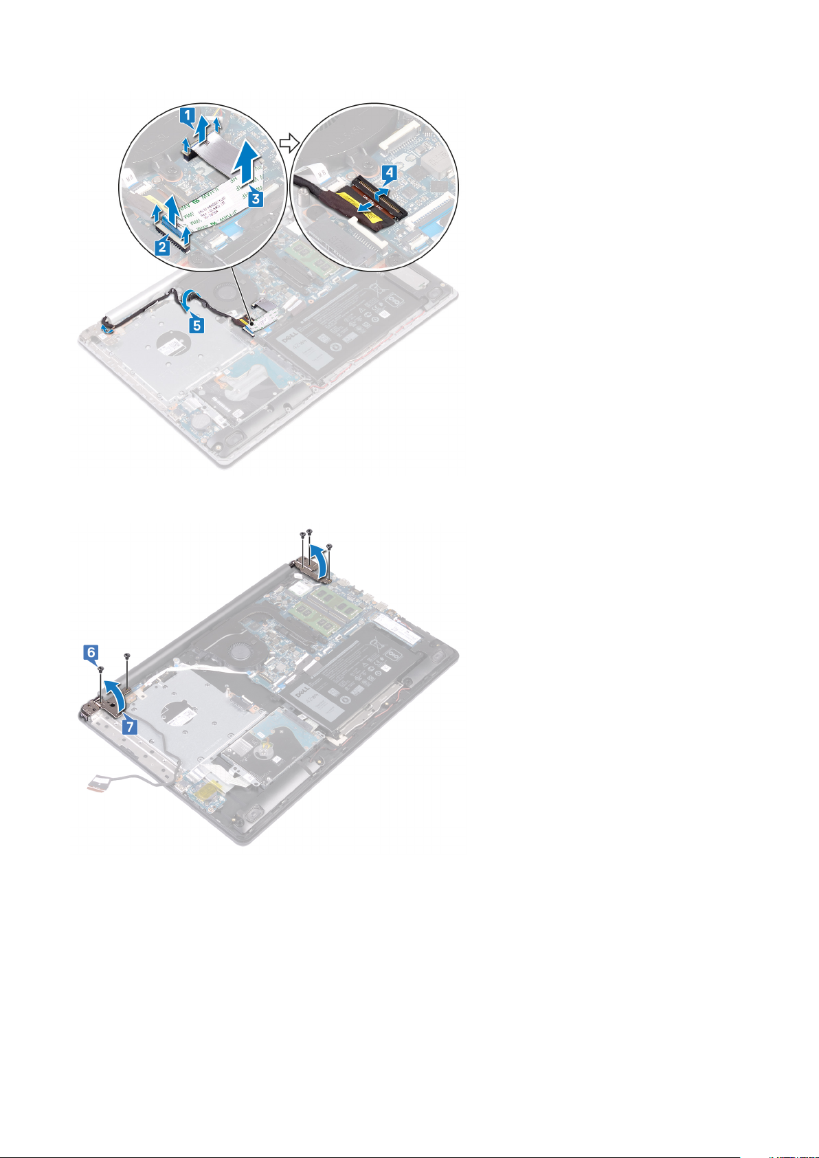
6. Remove the five screws (M2.5x5) that secure the left and right hinges to the system board and palm rest and keyboard assembly.
7. Open the hinges.
8. Lift the palm rest and keyboard assembly at an angle.
9. Slide and remove the palm rest and keyboard assembly off the display assembly.
Removing the power-adapter port
59
Page 60

10. After performing all the above steps, you are left with display assembly.
Procedure
1. Remove the three screws (M2.5x5) that secure the right hinge to the system board and palm rest assembly.
2. Lift the right hinge.
3. Disconnect the power-adapter port cable from the system board.
4. Note the power-adapter port cable routing and remove it from the routing guides on the palm rest and keyboard assembly.
5. Remove the screw (M2x3) that secures the power-adapter port to the palm rest and keyboard assembly.
6. Lift the power-adapter port, along with its cable, off the palm rest and keyboard assembly.
60
Removing the power-adapter port
Page 61

Removing the power-adapter port 61
Page 62

Replacing the power-adapter port
NOTE: Before working inside your computer, read the safety information that shipped with your computer and follow
the steps in Before working inside your computer. After working inside your computer, follow the instructions in After
working inside your computer. For more safety best practices, see the Regulatory Compliance home page at
www.dell.com/regulatory_compliance.
Procedure
1. Align the screw hole on the power-adapter port with the screw hole on the palm rest and keyboard assembly.
2. Replace the screw (M2x3) that secures the power-adapter port to the palm rest and keyboard assembly.
3. Route the power-adapter port cable through the routing guides on the palm rest and keyboard assembly.
4. Connect the power-adapter port cable to the system board.
5. Close the right hinge.
6. Replace the three screws (M2.5x5) that secure the right hinge to the system board and palm rest assembly.
33
Replacing the display assembly
NOTE:
the steps in Before working inside your computer. After working inside your computer, follow the instructions in After
working inside your computer. For more safety best practices, see the Regulatory Compliance home page at
www.dell.com/regulatory_compliance.
Procedure
NOTE:
keyboard assembly.
1. Slide the palm rest and keyboard assembly under the hinges on the display assembly and close it.
62 Replacing the power-adapter port
Before working inside your computer, read the safety information that shipped with your computer and follow
Ensure that the hinges are opened to the maximum before replacing the display assembly on palm rest and
Page 63

2. Using the alignment posts, press the hinges down on the system board and the palm rest and keyboard assembly.
3. Replace the five screws (M2.5x5) that secure the left and right hinges to the system board and palm rest and keyboard assembly.
4. Route the display cable through the routing guides on the fan and the palm rest and keyboard assembly.
5. Slide the display cable to the connector on the system board and close the latch to secure the cable.
6. Press down on the latch to connect the optical-drive connector board cable to the optical-drive connector board.
7. Press down on the latch to connect the optical-drive connector board cable to the system board.
Replacing the power-adapter port
63
Page 64

Post-requisites
1. Replace the wireless card.
2. Replace the base cover.
3. Replace the optical drive.
64
Replacing the power-adapter port
Page 65
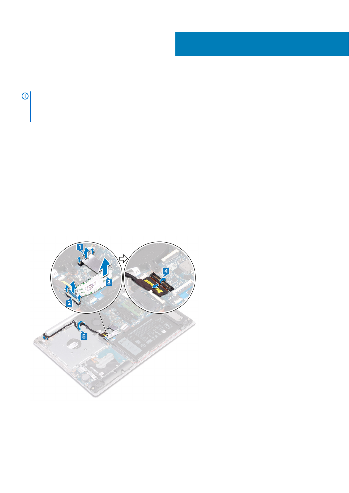
34
Removing the display assembly
NOTE: Before working inside your computer, read the safety information that shipped with your computer and follow
the steps in Before working inside your computer. After working inside your computer, follow the instructions in After
working inside your computer. For more safety best practices, see the Regulatory Compliance home page at
www.dell.com/regulatory_compliance.
Prerequisites
1. Remove the optical drive.
2. Remove the base cover.
3. Remove the wireless card.
Procedure
1. Lift the latch and disconnect the optical-drive connector-board cable from the system board.
2. Lift the latch and disconnect the optical-drive connector-board cable from the optical-drive board connector.
3. Lift the optical-drive connector-board cable off the system board.
4. Open the latch and disconnect the display cable from the system board.
5. Note the routing of the display cable and remove the cable from its routing guides on the fan and palm rest and keyboard assembly.
6. Remove the five screws (M2.5x5) that secure the left and right hinges to the system board and palm rest and keyboard assembly.
7. Open the hinges.
Removing the display assembly 65
Page 66

8. Lift the palm rest and keyboard assembly at an angle.
9. Slide and remove the palm rest and keyboard assembly off the display assembly.
10. After performing all the above steps, you are left with display assembly.
66
Removing the display assembly
Page 67

Removing the display assembly 67
Page 68

Replacing the display assembly
NOTE: Before working inside your computer, read the safety information that shipped with your computer and follow
the steps in Before working inside your computer. After working inside your computer, follow the instructions in After
working inside your computer. For more safety best practices, see the Regulatory Compliance home page at
www.dell.com/regulatory_compliance.
Procedure
NOTE: Ensure that the hinges are opened to the maximum before replacing the display assembly on palm rest and
keyboard assembly.
1. Slide the palm rest and keyboard assembly under the hinges on the display assembly and close it.
35
2. Using the alignment posts, press the hinges down on the system board and the palm rest and keyboard assembly.
3. Replace the five screws (M2.5x5) that secure the left and right hinges to the system board and palm rest and keyboard assembly.
68 Replacing the display assembly
Page 69

4. Route the display cable through the routing guides on the fan and the palm rest and keyboard assembly.
5. Slide the display cable to the connector on the system board and close the latch to secure the cable.
6. Press down on the latch to connect the optical-drive connector board cable to the optical-drive connector board.
7. Press down on the latch to connect the optical-drive connector board cable to the system board.
Post-requisites
1. Replace the wireless card.
2. Replace the base cover.
3. Replace the optical drive.
Replacing the display assembly
69
Page 70

Removing the I/O board
NOTE: Before working inside your computer, read the safety information that shipped with your computer and follow
the steps in Before working inside your computer. After working inside your computer, follow the instructions in After
working inside your computer. For more safety best practices, see the Regulatory Compliance home page at
www.dell.com/regulatory_compliance.
Prerequisites
CAUTION: Removing the coin-cell battery resets the BIOS setup program’s settings to default. Before removing the I/O
board along with the coin-cell battery, it is recommended to note the BIOS setup program’s settings.
1. Remove the optical drive.
2. Remove the base cover.
3. Remove the battery.
4. Remove the hard drive.
Procedure
36
1. Open the latch and disconnect the I/O-board cable from the system board.
2. Peel the I/O-board cable from the palm rest and keyboard assembly.
3. Remove the screw (M2x4) that secures the I/O board to the palm rest and keyboard assembly.
4. Lift the I/O board, along with the cable, off the palm rest and keyboard assembly.
70 Removing the I/O board
Page 71
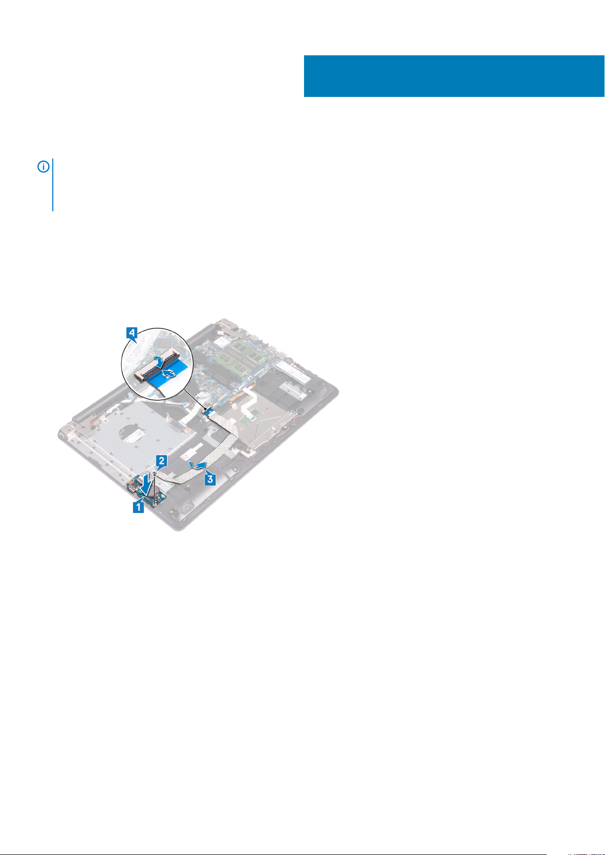
Replacing the I/O board
NOTE: Before working inside your computer, read the safety information that shipped with your computer and follow
the steps in Before working inside your computer. After working inside your computer, follow the instructions in After
working inside your computer. For more safety best practices, see the Regulatory Compliance home page at
www.dell.com/regulatory_compliance.
Procedure
1. Using the alignment posts, place the I/O board on the palm rest and keyboard assembly.
2. Replace the screw (M2x4) that secures the I/O board to the palm rest and keyboard assembly.
3. Adhere the I/O-board cable to the palm rest and keyboard assembly.
4. Connect the I/O-board cable to the system board and close the latch to secure the cable.
37
Post-requisites
1. Replace the hard drive.
2. Replace the battery.
3. Replace the base cover.
4. Replace the optical drive.
Replacing the I/O board 71
Page 72

Removing the power-button board
NOTE: Before working inside your computer, read the safety information that shipped with your computer and follow
the steps in Before working inside your computer. After working inside your computer, follow the instructions in After
working inside your computer. For more safety best practices, see the Regulatory Compliance home page at
www.dell.com/regulatory_compliance.
Prerequisites
1. Remove the optical drive.
2. Remove the base cover.
3. Remove the fan.
Procedure
1. Remove the two screws (M2.5x5) that secure the left hinge to palm rest and keyboard assembly.
2. Open the left hinge.
38
3. Open the latch and disconnect the power-button board cable from the system board.
4. Peel off the tape that secures the power-button board to the palm rest and keyboard assembly.
5. Remove the screw (M2x2) that secures the power-button board to the palm rest and keyboard assembly.
6. Lift the power-button board, along with the cable, off the palm rest and keyboard assembly.
72 Removing the power-button board
Page 73

Removing the power-button board 73
Page 74
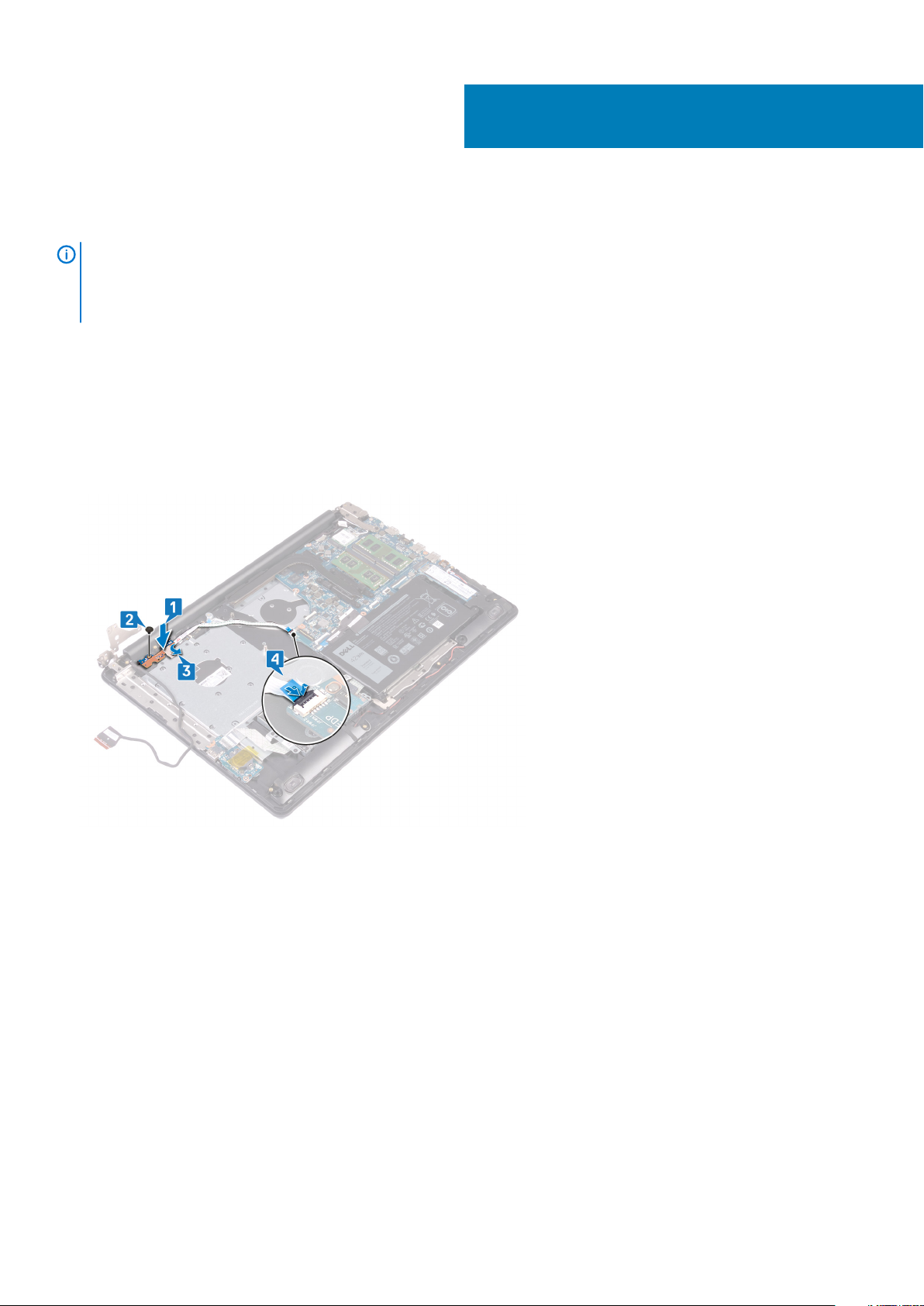
39
Replacing the power-button board
NOTE: Before working inside your computer, read the safety information that shipped with your computer and follow
the steps in Before working inside your computer. After working inside your computer, follow the instructions in After
working inside your computer. For more safety best practices, see the Regulatory Compliance home page at
www.dell.com/regulatory_compliance.
Procedure
1. Place the power-button board on the palm rest and keyboard assembly and align the screw hole on the power-button board with the
screw hole on the palm rest and keyboard assembly.
2. Replace the screw (M2x2) that secures the power-button board to the palm rest and keyboard assembly.
3. Adhere the tape that secures the power-button board to the palm rest and keyboard assembly.
4. Slide the power-button cable to the system board and close the latch to secure the cable.
5. Close the left hinge.
6. Replace the two screws (M2.5x5) that secure the left hinge to palm rest and keyboard assembly.
74 Replacing the power-button board
Page 75
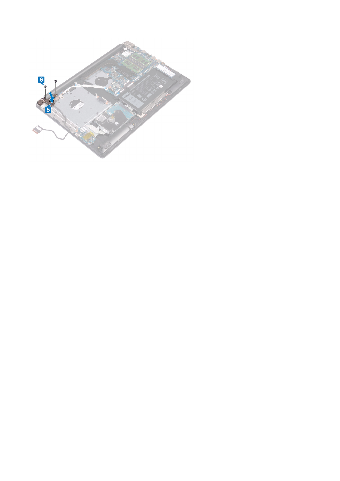
Post-requisites
1. Replace the fan.
2. Replace the base cover.
3. Replace the optical drive.
Replacing the power-button board
75
Page 76

Removing the system board
NOTE: Before working inside your computer, read the safety information that shipped with your computer and follow
the steps in Before working inside your computer. After working inside your computer, follow the instructions in After
working inside your computer. For more safety best practices, see the Regulatory Compliance home page at
www.dell.com/regulatory_compliance.
NOTE: Your computer’s Service Tag is stored in the system board. You must enter the Service Tag in the BIOS setup
program after you replace the system board.
NOTE: Replacing the system board removes any changes you have made to the BIOS using the BIOS setup program. You
must make the appropriate changes again after you replace the system board.
NOTE: Before disconnecting the cables from the system board, note the location of the connectors so that you can
reconnect the cables correctly after you replace the system board.
Prerequisites
1. Remove the optical drive.
2. Remove the base cover.
3. Remove the battery.
4. Remove the memory modules.
5. Remove the wireless card.
6. Remove the solid-state drive/Intel Optane.
7. Remove the fan.
8. Remove the heat sink.
40
Procedure
1. Disconnect the power-adapter port cable from the system board.
2. Disconnect the speaker cable from the system board.
3. Open the latch and disconnect the keyboard from the system board.
4. Open the latch and disconnect the keyboard back-light cable from the system board.
5. Open the latch and disconnect the touchpad cable from the system board.
6. Open the latch and disconnect the hard-drive cable from the system board.
7. Open the latch and disconnect the I/O board cable from the system board.
8. Open the latch and disconnect the finger-print reader cable from the system board.
9. Open the latch and disconnect the power-button board cable from the system board.
76 Removing the system board
Page 77
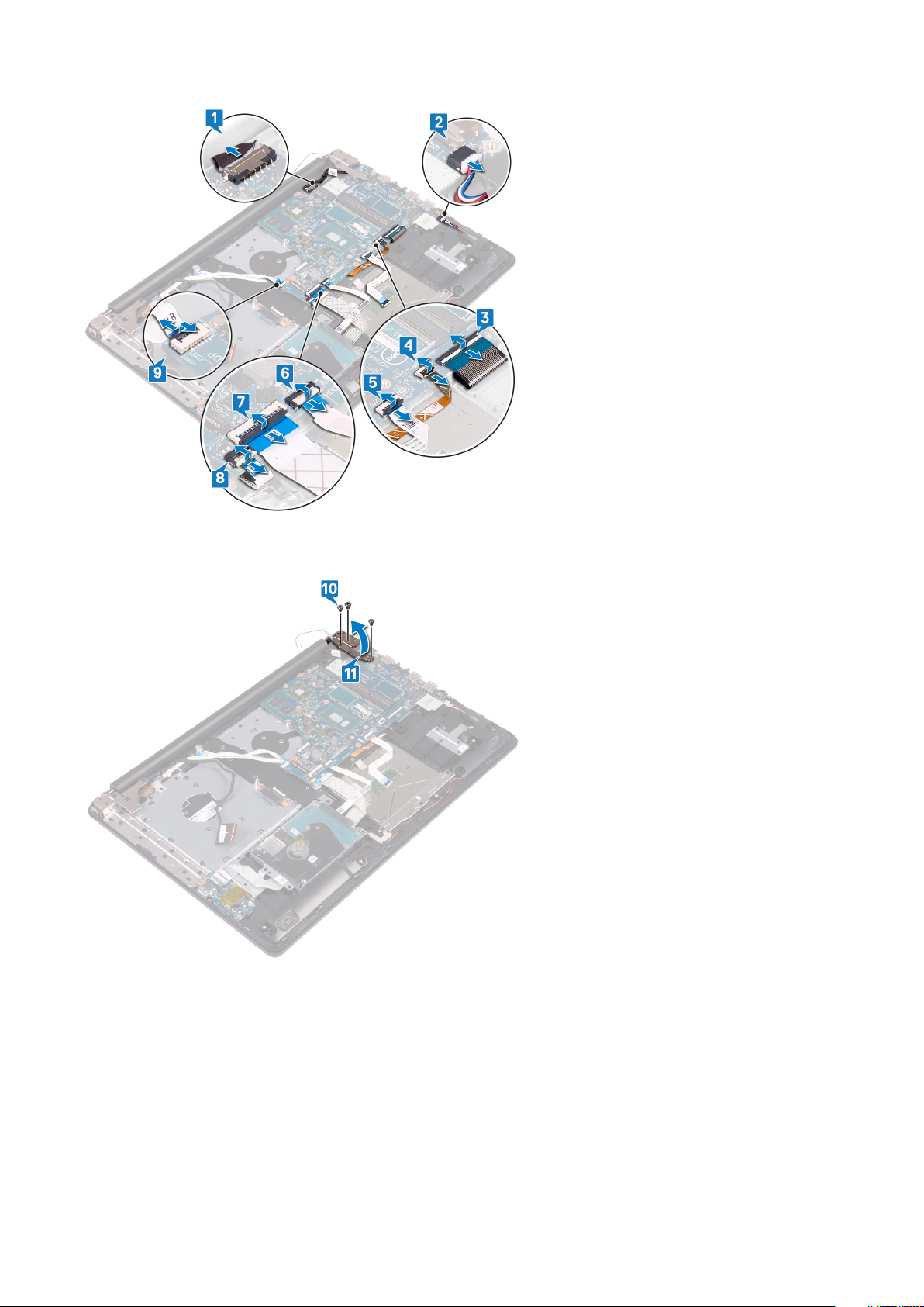
10. Remove the three screws (M2.5x5) that secure the right hinge to the system board.
11. Open the right hinge.
12. Remove the screw (M2x4) that secures the system board to palm rest and keyboard assembly.
13. Lift the system board off the palm rest and keyboard assembly.
Removing the system board
77
Page 78

78 Removing the system board
Page 79
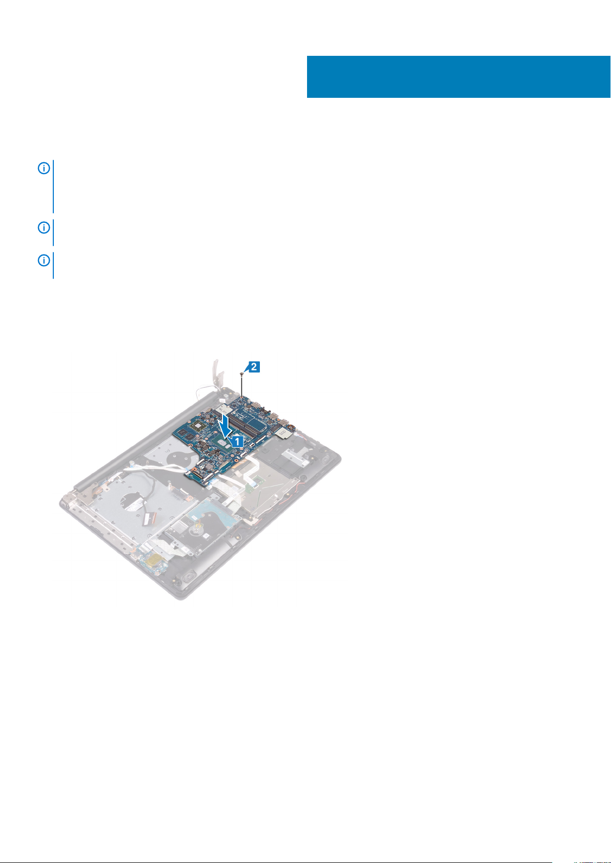
Replacing the system board
NOTE: Before working inside your computer, read the safety information that shipped with your computer and follow
the steps in Before working inside your computer. After working inside your computer, follow the instructions in After
working inside your computer. For more safety best practices, see the Regulatory Compliance home page at
www.dell.com/regulatory_compliance.
NOTE: Your computer’s Service Tag is stored in the system board. You must enter the Service Tag in the BIOS setup
program after you replace the system board.
NOTE: Replacing the system board removes any changes you have made to the BIOS using the BIOS setup program. You
must make the appropriate changes again after you replace the system board.
Procedure
1. Align the screw hole on the system board with the screw hole on the palm rest and keyboard assembly.
2. Replace the screw (M2x4) that secures the system board to the palm rest and keyboard assembly.
41
3. Close the right display hinge.
4. Replace the three screws (M2.5x5) that secure the right hinge to the system board.
Replacing the system board 79
Page 80

5. Connect the power-adapter port cable and speaker cable to the system board.
6. Slide the keyboard back-light cable and keyboard cable into their respective connectors on the system board and close the latches.
7. Slide the touchpad cable and hard-drive cable into their respective connectors on the system board and close the latches.
8. Slide the I/O-board cable and finger-print reader cable into their respective connectors on the system board and close the latch.
9. Slide the power-button board cable into the connector on the system board and close the latch.
Post-requisites
1. Replace the heat sink.
2. Replace the fan.
3. Replace the solid-state drive/Intel Optane.
4. Replace the wireless card.
80
Replacing the system board
Page 81

5. Replace the memory modules.
6. Replace the battery.
7. Replace the base cover.
8. Replace the optical drive.
Entering the Service Tag in the BIOS setup program
1. Turn on or restart your computer.
2. Press F2 when the Dell logo is displayed to enter the BIOS setup program.
3. Navigate to the Main tab and enter the Service Tag in the Service Tag Input field.
NOTE:
Service tag is the alphanumeric identifier located at the back side of your computer.
Replacing the system board 81
Page 82

Removing the power button with fingerprint
reader
NOTE: Before working inside your computer, read the safety information that shipped with your computer and follow
the steps in Before working inside your computer. After working inside your computer, follow the instructions in After
working inside your computer. For more safety best practices, see the Regulatory Compliance home page at
www.dell.com/regulatory_compliance.
NOTE: Applicable only for computers that are shipped with fingerprint reader.
Prerequisites
1. Remove the optical drive.
2. Remove the base cover.
3. Remove the battery.
4. Remove the solid-state drive/Intel Optane.
5. Remove the fan.
6. Remove the wireless card.
7. Remove the power-button board.
8. Remove the system board.
42
Procedure
1. Peel the fingerprint reader cable off the palm rest and keyboard assembly.
2. Remove the screw (M2x2) that secures the power button with fingerprint reader to the palm rest and keyboard assembly.
3. Using a plastic scribe, release the fingerprint-reader board from the palm rest and keyboard assembly.
4. Lift the power button with fingerprint reader, along with its cable, off the palm rest and keyboard assembly.
82 Removing the power button with fingerprint reader
Page 83

Replacing the power button with fingerprint
reader
NOTE: Before working inside your computer, read the safety information that shipped with your computer and follow
the steps in Before working inside your computer. After working inside your computer, follow the instructions in After
working inside your computer. For more safety best practices, see the Regulatory Compliance home page at
www.dell.com/regulatory_compliance.
NOTE: Applicable only for computers that are shipped with fingerprint reader.
Procedure
1. Using the alignment posts, align and place the power button with fingerprint reader on the palm rest and keyboard assembly.
2. Replace the screw (M2x2) that secures the power button with fingerprint reader to the palm rest and keyboard assembly.
3. Adhere the fingerprint reader cable on the palm rest and keyboard assembly.
43
Post-requisites
1. Replace the system board.
2. Replace the power-button board.
3. Replace the wireless card.
4. Replace the fan.
5. Replace the solid-state drive/Intel Optane.
6. Replace the battery.
7. Replace the base cover.
8. Replace the optical drive.
Replacing the power button with fingerprint reader 83
Page 84

Removing the palm-rest and keyboard
assembly
NOTE: Before working inside your computer, read the safety information that shipped with your computer and follow
the steps in Before working inside your computer. After working inside your computer, follow the instructions in After
working inside your computer. For more safety best practices, see the Regulatory Compliance home page at
www.dell.com/regulatory_compliance.
Prerequisites
1. Remove the optical drive.
2. Remove the base cover.
3. Remove the battery.
4. Remove the optical-drive connector board.
5. Remove the fan.
6. Remove the solid-state drive/Intel Optane.
7. Remove the wireless card.
8. Remove the speakers.
9. Remove the hard drive.
10. Remove the touchpad.
11. Remove the power-adapter port.
12. Remove the display assembly.
13. Remove the I/O board.
14. Remove the power-button board.
15. Remove the system board.
16. Remove the power button with fingerprint reader (optional).
44
Procedure
After performing the above steps, we are left with the palm rest and keyboard assembly.
84 Removing the palm-rest and keyboard assembly
Page 85

Removing the palm-rest and keyboard assembly 85
Page 86

Replacing the palm-rest and keyboard
assembly
NOTE: Before working inside your computer, read the safety information that shipped with your computer and follow
the steps in Before working inside your computer. After working inside your computer, follow the instructions in After
working inside your computer. For more safety best practices, see the Regulatory Compliance home page at
www.dell.com/regulatory_compliance.
Procedure
45
Place the palm rest and keyboard assembly on a flat surface.
Post-requisites
1. Replace the power button with fingerprint reader (optional).
2. Replace the system board.
3. Replace the power-button board.
4. Replace the I/O board.
5. Replace the display assembly.
6. Replace the power-adapter port.
7. Replace the touchpad.
8. Replace the hard drive.
9. Replace the speakers.
10. Replace the wireless card.
11. Replace the solid-state drive/Intel Optane.
12. Replace the fan.
13. Replace the optical-drive connector board.
14. Replace the battery.
15. Replace the base cover.
16. Replace the optical drive.
86 Replacing the palm-rest and keyboard assembly
Page 87

46
Removing the display bezel
NOTE: Before working inside your computer, read the safety information that shipped with your computer and follow
the steps in Before working inside your computer. After working inside your computer, follow the instructions in After
working inside your computer. For more safety best practices, see the Regulatory Compliance home page at
www.dell.com/regulatory_compliance.
Prerequisites
1. Remove the optical drive.
2. Remove the base cover.
3. Remove the wireless card.
4. Remove the display assembly.
Procedure
1. Using a plastic scribe, carefully pry up the display bezel from the top-left outer edge of the display back-cover and antenna assembly.
2. Remove the display bezel off the display back-cover and antenna assembly.
Removing the display bezel 87
Page 88

Replacing the display bezel
NOTE: Before working inside your computer, read the safety information that shipped with your computer and follow
the steps in Before working inside your computer. After working inside your computer, follow the instructions in After
working inside your computer. For more safety best practices, see the Regulatory Compliance home page at
www.dell.com/regulatory_compliance.
Procedure
Align the display bezel with the display back-cover and antenna assembly, and then gently snap the display bezel into place.
47
Post-requisites
1. Replace the display assembly.
2. Replace the wireless card.
3. Replace the base cover.
4. Replace the optical drive.
88 Replacing the display bezel
Page 89

Removing the camera
NOTE: Before working inside your computer, read the safety information that shipped with your computer and follow
the steps in Before working inside your computer. After working inside your computer, follow the instructions in After
working inside your computer. For more safety best practices, see the Regulatory Compliance home page at
www.dell.com/regulatory_compliance.
Prerequisites
1. Remove the optical drive.
2. Remove the base cover.
3. Remove the wireless card.
4. Remove the display assembly.
5. Remove the display bezel.
Procedure
1. Using a plastic scribe, gently pry the camera off the display back-cover and antenna assembly.
2. Disconnect the camera cable from the camera module.
3. Lift the camera module from the display back-cover and antenna assembly.
48
Removing the camera 89
Page 90

Replacing the camera
NOTE: Before working inside your computer, read the safety information that shipped with your computer and follow
the steps in Before working inside your computer. After working inside your computer, follow the instructions in After
working inside your computer. For more safety best practices, see the Regulatory Compliance home page at
www.dell.com/regulatory_compliance.
Procedure
1. Connect the camera cable to the camera module.
2. Using the alignment post adhere the camera module on the display back-cover and antenna assembly.
49
Post-requisites
1. Replace the display bezel.
2. Replace the display assembly.
3. Replace the wireless card.
4. Replace the base cover.
5. Replace the optical drive.
90 Replacing the camera
Page 91

Removing the display panel
NOTE: Before working inside your computer, read the safety information that shipped with your computer and follow
the steps in Before working inside your computer. After working inside your computer, follow the instructions in After
working inside your computer. For more safety best practices, see the Regulatory Compliance home page at
www.dell.com/regulatory_compliance.
Prerequisites
1. Remove the base cover.
2. Remove the wireless card.
3. Remove the display assembly.
4. Remove the display bezel.
Procedure
1. Remove the four screws (M2x3) that secure the display panel to the display back-cover and antenna assembly.
2. Lift the display panel and turn it over.
50
3. Peel the tape adhering the display cable to the back of the display panel.
4. Lift the latch and disconnect the display cable from the display-panel cable connector.
5. Lift the display panel away from the display back-cover and antenna assembly.
Removing the display panel 91
Page 92

92 Removing the display panel
Page 93
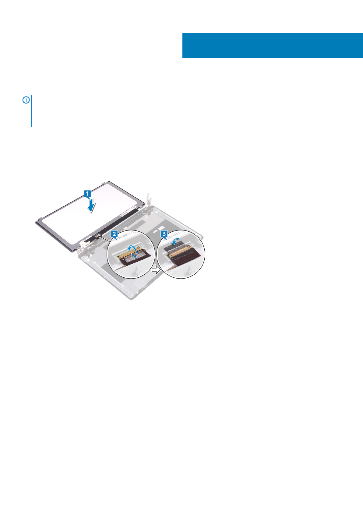
Replacing the display panel
NOTE: Before working inside your computer, read the safety information that shipped with your computer and follow
the steps in Before working inside your computer. After working inside your computer, follow the instructions in After
working inside your computer. For more safety best practices, see the Regulatory Compliance home page at
www.dell.com/regulatory_compliance.
Procedure
1. Place the display panel on a flat and clean surface.
2. Connect the display cable to the connector at the back of the display panel and close the latch to secure the cable.
3. Adhere the tape that secures the display cable to the back of the display panel.
51
4. Place the display panel on the display back-cover and antenna assembly.
5. Align the screw holes on the display panel with the screw holes on the display back-cover and antenna assembly.
6. Replace the four screws (M2x3) that secure the display panel to the display back-cover and antenna assembly.
Replacing the display panel 93
Page 94
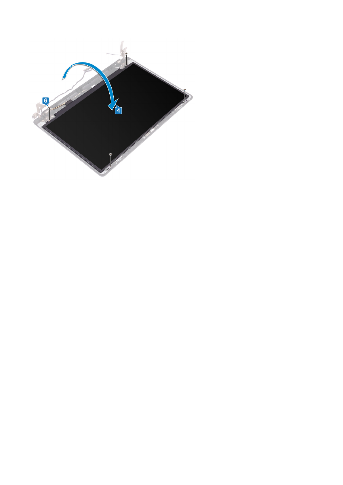
Post-requisites
1. Replace the display bezel.
2. Replace the display assembly.
3. Replace the wireless card.
4. Replace the base cover.
94
Replacing the display panel
Page 95
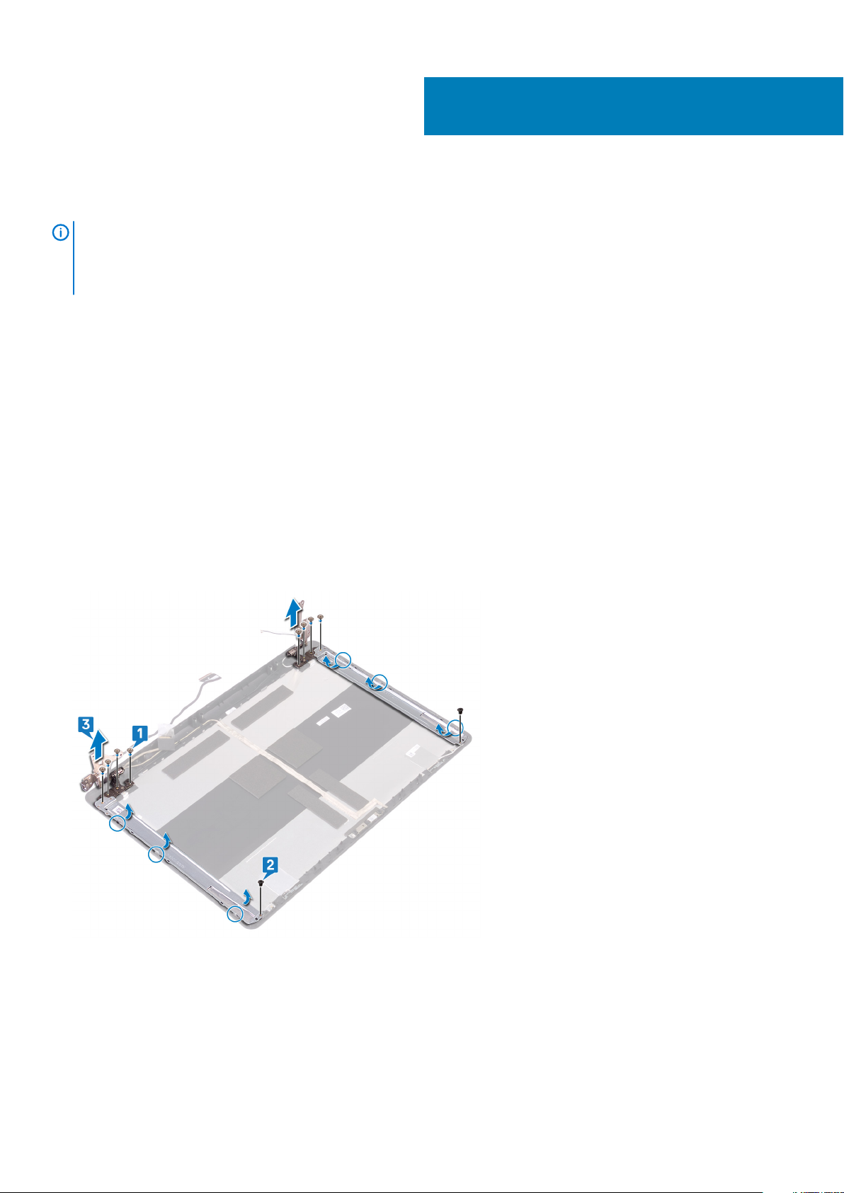
Removing the display hinges
NOTE: Before working inside your computer, read the safety information that shipped with your computer and follow
the steps in Before working inside your computer. After working inside your computer, follow the instructions in After
working inside your computer. For more safety best practices, see the Regulatory Compliance home page at
www.dell.com/regulatory_compliance.
Prerequisites
1. Remove the optical drive.
2. Remove the base cover.
3. Remove the wireless card.
4. Remove the display assembly.
5. Remove the display bezel.
6. Remove the display panel.
Procedure
52
1. Remove the eight screws (M2.5x4) that secure the display hinges to the display back-cover and antenna assembly.
2. Remove the two screws (M2x3) that secure the display-hinge brackets to the display back-cover and antenna assembly.
3. Lift the display hinges and brackets off the display back-cover and antenna assembly.
Removing the display hinges 95
Page 96

Replacing the display hinges
NOTE: Before working inside your computer, read the safety information that shipped with your computer and follow
the steps in Before working inside your computer. After working inside your computer, follow the instructions in After
working inside your computer. For more safety best practices, see the Regulatory Compliance home page at
www.dell.com/regulatory_compliance.
Procedure
1. Align the screw holes on the display hinges and brackets with the screw holes on the display back-cover and antenna assembly.
2. Replace the two screws (M2x3) that secure the display-hinge brackets to the display back-cover and antenna assembly.
3. Replace the eight screws (M2.5x4) that secure the display hinges to the display back-cover and antenna assembly .
53
Post-requisites
1. Replace the display panel.
2. Replace the display bezel.
3. Replace the display assembly.
4. Replace the wireless card.
5. Replace the base cover.
6. Replace the optical drive.
96 Replacing the display hinges
Page 97

Removing the display cable
NOTE: Before working inside your computer, read the safety information that shipped with your computer and follow
the steps in Before working inside your computer. After working inside your computer, follow the instructions in After
working inside your computer. For more safety best practices, see the Regulatory Compliance home page at
www.dell.com/regulatory_compliance.
Prerequisites
1. Remove the optical drive.
2. Remove the base cover.
3. Remove the wireless card.
4. Remove the display assembly.
5. Remove the display bezel.
6. Remove the display panel.
7. Remove the display hinges.
Procedure
54
1. Disconnect the camera cable from the camera module.
2. Note the display cable routing and remove the cable from the routing guides on the display back-cover and antenna assembly.
3. Remove the display cable from the display back-cover and antenna assembly.
Removing the display cable 97
Page 98

Replacing the display cable
NOTE: Before working inside your computer, read the safety information that shipped with your computer and follow
the steps in Before working inside your computer. After working inside your computer, follow the instructions in After
working inside your computer. For more safety best practices, see the Regulatory Compliance home page at
www.dell.com/regulatory_compliance.
Procedure
1. Route the display cable through the routing guides on the display back-cover and antenna assembly.
2. Slide the camera cable into the connector on the camera module to secure the cable.
55
Post-requisites
1. Replace the display hinges.
2. Replace the display panel.
3. Replace the display bezel.
4. Replace the display assembly.
5. Replace the wireless card.
6. Replace the base cover.
7. Replace the optical drive.
98 Replacing the display cable
Page 99

56
Removing the display back-cover and antenna
assembly
NOTE: Before working inside your computer, read the safety information that shipped with your computer and follow
the steps in Before working inside your computer. After working inside your computer, follow the instructions in After
working inside your computer. For more safety best practices, see the Regulatory Compliance home page at
www.dell.com/regulatory_compliance.
Prerequisites
1. Remove the optical drive.
2. Remove the base cover.
3. Remove the wireless card.
4. Remove the display assembly.
5. Remove the display bezel.
6. Remove the camera.
7. Remove the display panel.
8. Remove the display hinges.
9. Remove the display cable.
Procedure
After performing all the above steps, we are left with the display back-cover and antenna assembly.
Removing the display back-cover and antenna assembly 99
Page 100

57
Replacing the display back-cover and antenna
assembly
NOTE: Before working inside your computer, read the safety information that shipped with your computer and follow
the steps in Before working inside your computer. After working inside your computer, follow the instructions in After
working inside your computer. For more safety best practices, see the Regulatory Compliance home page at
www.dell.com/regulatory_compliance.
Procedure
Place the display back-cover and antenna assembly on a clean and flat surface.
Post-requisites
1. Replace the display cable.
2. Replace the display hinges.
3. Replace the display panel.
4. Replace the camera.
5. Replace the display bezel.
6. Replace the display assembly.
7. Replace the wireless card.
8. Replace the base cover.
9. Replace the optical drive.
100 Replacing the display back-cover and antenna assembly
 Loading...