

Page 1

Dell Inspiron 2100
Dell™ Inspiron™ 2100
A Tour of Your Computer
Power Conservation
Solving Problems
System Specifications
Drivers and Utilities
System Setup Program
Ports and Connector Pin-Outs
Removing and Replacing Parts
Hints, Notices, and Cautions
HINT: A HINT indicates important information that helps you make better use of your
computer.
NOTICE: A NOTICE indicates either potential damage to hardware or loss of data and tells you
how to avoid the problem.
CAUTION: A CAUTION indicates a potentially hazardous situation which, if not
avoided, may result in minor or moderate injury.
Abbreviations and Acronyms
For a complete list of abbreviations and acronyms, see the Glossary in the Tell Me How help file (click
Start, point to Programs, point to User's Guides, and then click Tell Me How).
Information in this document is subject to change without notice.
© 2001 Dell Computer Corporation. All rights reserved.
Reproduction in any manner whatsoever without the written permission of Dell Computer Corporation is strictly forbidden.
Trademarks used in this text: Dell, the DELL logo, Dell TravelLite, Inspiron, and DellWare are trademarks of Dell Computer
Corporation; Intel is a registered trademark of Intel Corporation; Microsoft and Windows are registered trademarks of
Microsoft Corporation.
Other trademarks and trade names may be used in this document to refer to either the entities claiming the marks and
names or their products. Dell Computer Corporation disclaims any proprietary interest in trademarks and trade names other
than its own.
file:///I|/SERVICE%20MANUALS/DELL%20MANUALS/LAP..._checked%20ok/Inspiron/2100/2100%20SM/index.htm (1 of 2)6/21/2004 12:43:30 AM
Page 2

Dell Inspiron 2100
A01 5 Mar 2001
file:///I|/SERVICE%20MANUALS/DELL%20MANUALS/LAP..._checked%20ok/Inspiron/2100/2100%20SM/index.htm (2 of 2)6/21/2004 12:43:30 AM
Page 3

A Tour of Your Computer : Dell Inspiron 2100
Back to Contents Page
A Tour of Your Computer
Dell™ Inspiron™ 2100
Front View
Left Side View
Right Side View
Back View
Bottom View
External Media Bay
Front View
file:///I|/SERVICE%20MANUALS/DELL%20MANUALS/LA..._checked%20ok/Inspiron/2100/2100%20SM/tour.htm (1 of 13)6/21/2004 12:43:33 AM
Page 4
A Tour of Your Computer : Dell Inspiron 2100
Display Latch
This tab keeps the display locked in place when the display is closed.
Display
The computer has a color LCD.
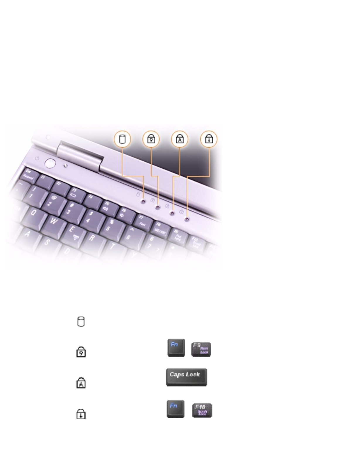
Device Status Lights
The green lights located above the keyboard indicate the following:
● The light labeled turns on when the computer reads or writes data.
● The light labeled turns on when you press to enable the numeric keypad.
● The light labeled turns on when you press to enable the uppercase letter function.
● The light labeled turns on when you press to enable the scroll lock function.
file:///I|/SERVICE%20MANUALS/DELL%20MANUALS/LA..._checked%20ok/Inspiron/2100/2100%20SM/tour.htm (2 of 13)6/21/2004 12:43:33 AM
Page 5
A Tour of Your Computer : Dell Inspiron 2100
NOTICE: To avoid data loss, never turn off the computer while the light labeled is
flashing.
Microphone
The internal microphone allows you to record voice audio.
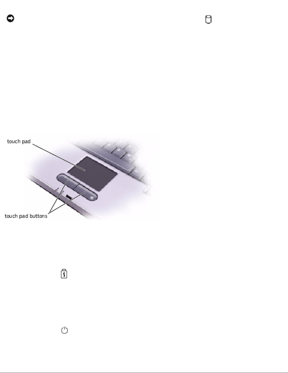
Touch Pad
The touch pad detects the position of your finger over a touch-sensitive area and provides the computer with full mouse
functionality.
Touch Pad Buttons
These buttons correspond to the left and right buttons on a standard mouse.
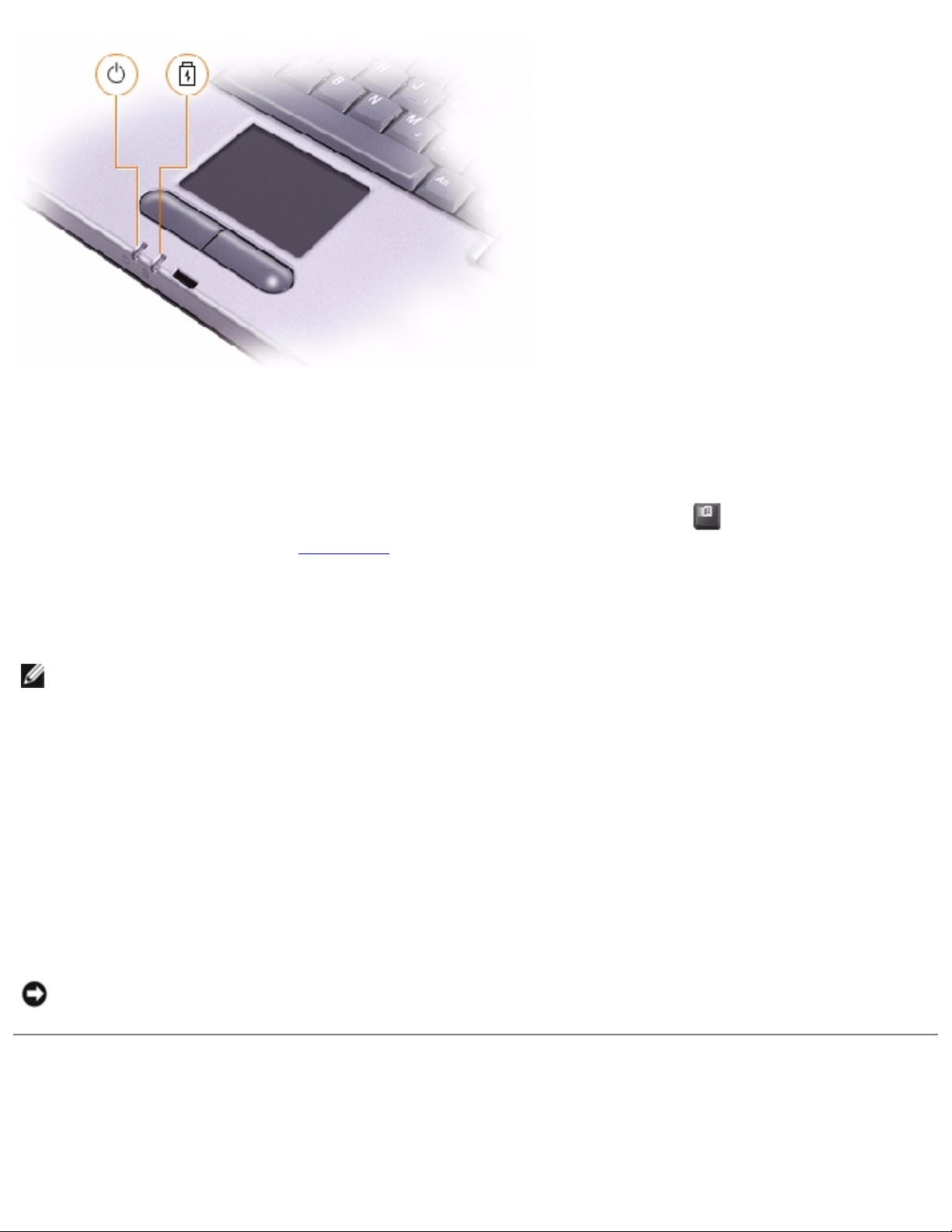
Status Lights
The lights below the display indicate the following:
● The light labeled turns on steadily or blinks to indicate battery charge status. Indicator states include:
❍ Solid green, which indicates that the battery is charging
❍ Flashing green, which indicates that the battery charge cycle is complete
❍ Flashing amber, which indicates that the battery charge is low
❍ Solid amber, which indicates that the battery charge is critically low
● The light labeled turns on when the computer is turned on.
file:///I|/SERVICE%20MANUALS/DELL%20MANUALS/LA..._checked%20ok/Inspiron/2100/2100%20SM/tour.htm (3 of 13)6/21/2004 12:43:33 AM
Page 6
A Tour of Your Computer : Dell Inspiron 2100
Keyboard
The keyboard includes a numeric keypad as well as the Microsoft® Windows® logo key, , which supports the
Windows operating systems. See the Tell Me How help file for information on your computer's supported key
combinations.
Power Button
HINT: To turn off your computer, perform a Windows
shutdown.
Press the power button to turn on the computer or to initiate standby mode. Depending on the computer's power
management settings, pressing the power button may activate hibernate or shutdown mode instead.
If the computer stops responding, press and hold the power button until the computer turns off completely (this may
take several seconds).
Display-Close Button
When you close the display, this button activates a power conservation mode that you can select on the Microsoft
Windows Power Options Properties window.
NOTICE: Do not press the display-close button with your
finger.
Left Side View
file:///I|/SERVICE%20MANUALS/DELL%20MANUALS/LA..._checked%20ok/Inspiron/2100/2100%20SM/tour.htm (4 of 13)6/21/2004 12:43:33 AM
Page 7
A Tour of Your Computer : Dell Inspiron 2100
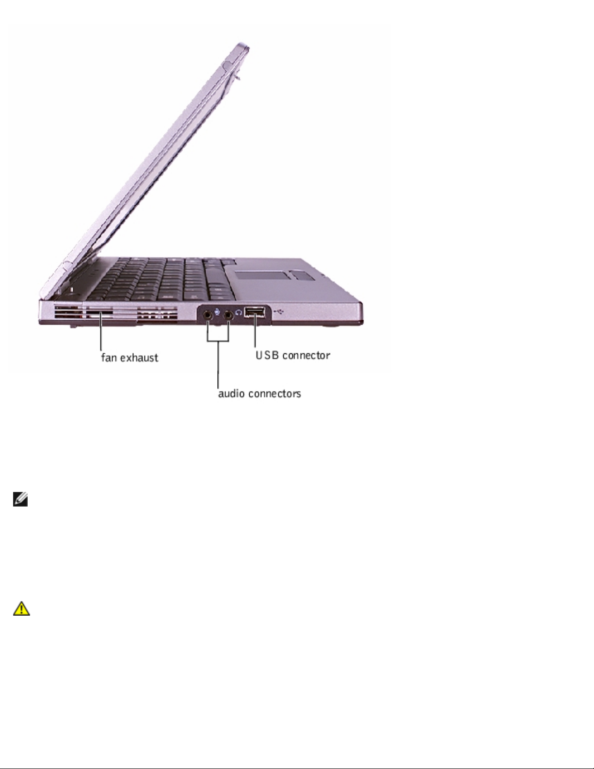
Fan Exhaust
HINT: The computer turns on the fan only when the computer gets hot. It may run most of the time or very
seldom, depending on your use of the computer. Because the fan spins at a high rate of speed, it may make a
noise. This noise is normal and does not indicate a problem with the fan or the computer.
The fan works with the air intakes to prevent the computer from overheating. When the computer gets hot, the small
internal fan turns on and draws air through the air intakes to cool the computer. Hot air is expelled through the fan
exhausts.
CAUTION: Do not push objects into or block the fan exhaust. Doing so can cause fire or damage the
interior components. Keep the opening free from dust and other foreign particles.
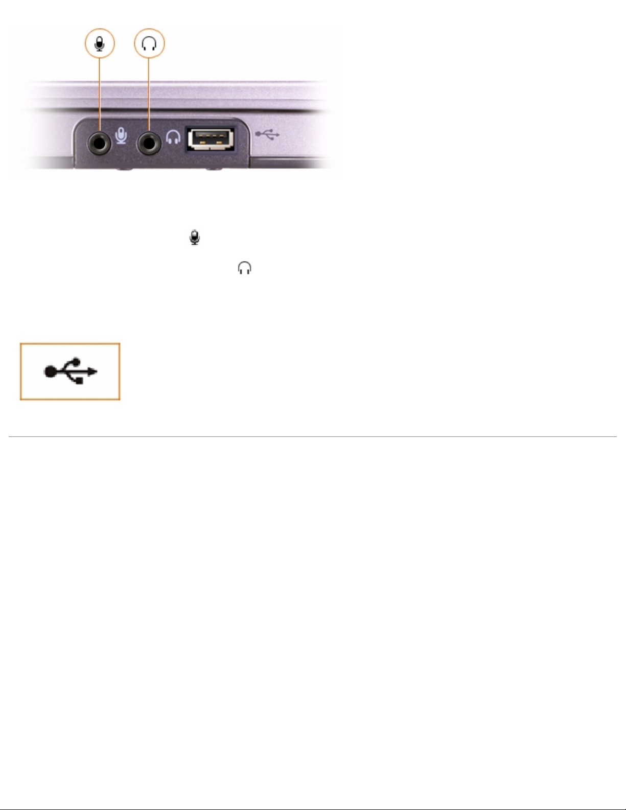
Audio Connectors
file:///I|/SERVICE%20MANUALS/DELL%20MANUALS/LA..._checked%20ok/Inspiron/2100/2100%20SM/tour.htm (5 of 13)6/21/2004 12:43:33 AM
Page 8
A Tour of Your Computer : Dell Inspiron 2100
● Attach a microphone to the connector.
● Attach headphones or speakers to the connector.
USB Connector
Use this connector to attach USB-compatible devices such as a mouse, keyboard, printer, or
scanner to your computer.
Right Side View
file:///I|/SERVICE%20MANUALS/DELL%20MANUALS/LA..._checked%20ok/Inspiron/2100/2100%20SM/tour.htm (6 of 13)6/21/2004 12:43:33 AM
Page 9
A Tour of Your Computer : Dell Inspiron 2100
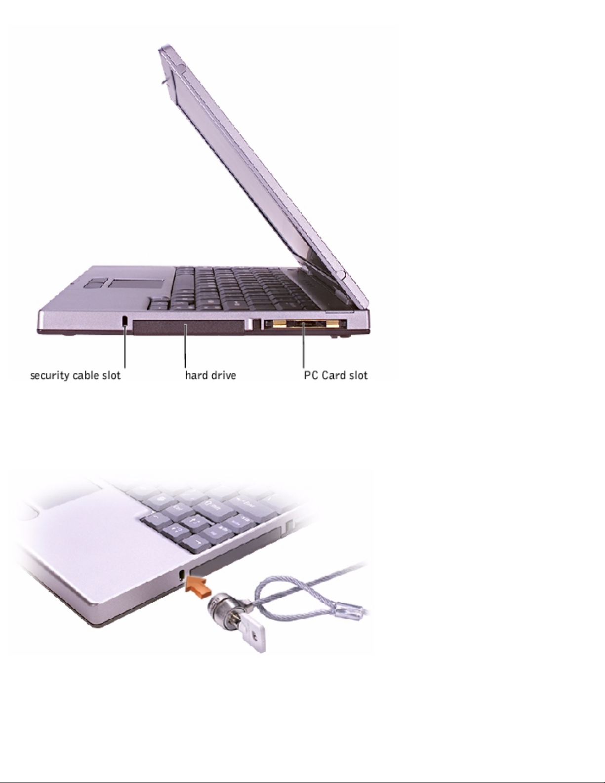
Security Cable Slot
The slot lets you attach a commercially available antitheft device to the computer. Complete instructions for installing
antitheft devices are usually included with the device.
file:///I|/SERVICE%20MANUALS/DELL%20MANUALS/LA..._checked%20ok/Inspiron/2100/2100%20SM/tour.htm (7 of 13)6/21/2004 12:43:33 AM
Page 10
A Tour of Your Computer : Dell Inspiron 2100
NOTICE: Antitheft devices are of differing designs. Before you buy one, make sure it will work with the security
cable slot in the computer.
Hard Drive
The hard drive reads and writes data on a hard disk.
PC Card Slot
The PC Card slot has one connector that supports various types of PC Cards, including modems and network cards. See
the
Tell Me How help file for more information on supported PC Cards and for installation and removal instructions.
Back View
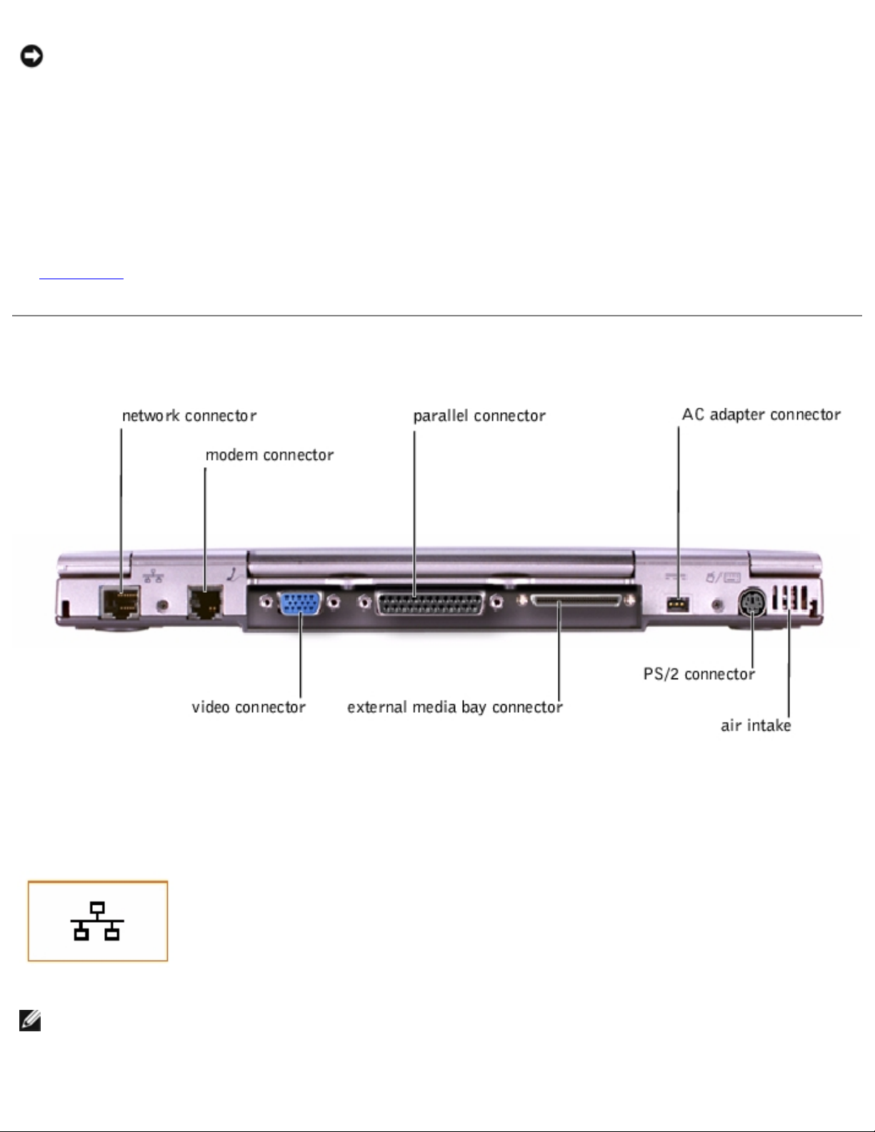
Network Connector
Use this connector to connect the computer to a
network.
HINT: The network connector is slightly larger than the modem connector. Do not plug a telephone line into the
network connector.
file:///I|/SERVICE%20MANUALS/DELL%20MANUALS/LA..._checked%20ok/Inspiron/2100/2100%20SM/tour.htm (8 of 13)6/21/2004 12:43:33 AM
Page 11
A Tour of Your Computer : Dell Inspiron 2100
Modem Connector
Use this connector to plug in the telephone
line.
Video Connector
Use this connector to attach an external monitor to the
computer.
Parallel Connector
Use this connector to attach a parallel device, such as a printer, to the
computer.
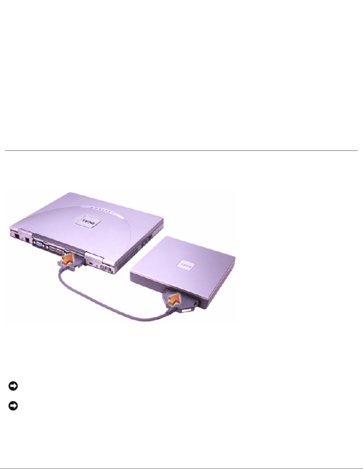
External Media Bay Connector
Use this connector to connect the external media
bay.
NOTICE: When you remove the media bay cable from the computer or a device, press in on the cable securing
clips while pulling the cable connector straight out. Do not insert or pull out the connector at an angle.
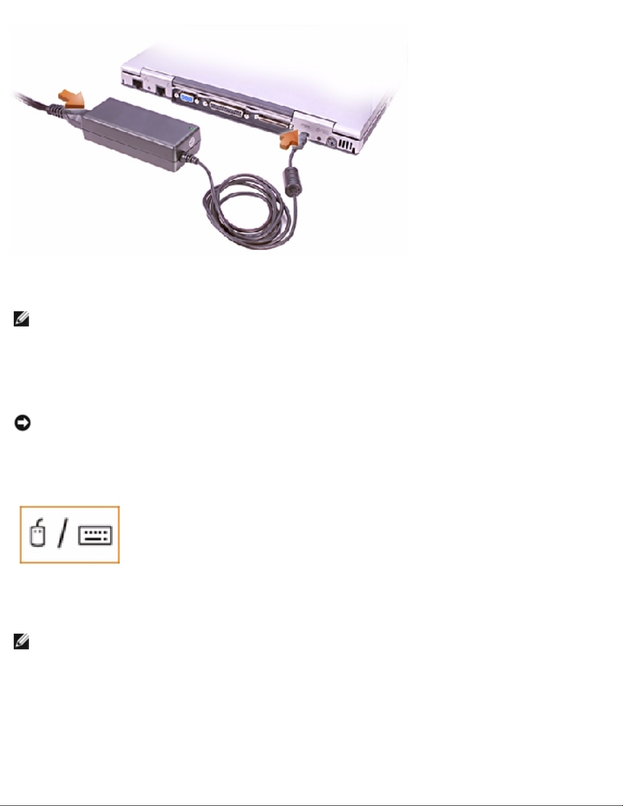
AC Adapter Connector
Use this connector to attach an AC adapter to the computer.
file:///I|/SERVICE%20MANUALS/DELL%20MANUALS/LA..._checked%20ok/Inspiron/2100/2100%20SM/tour.htm (9 of 13)6/21/2004 12:43:33 AM
Page 12
A Tour of Your Computer : Dell Inspiron 2100
HINT: Although the AC adapter works worldwide, power connectors vary among countries. Before using the AC
adapter in a foreign country, you may need to obtain a new power cable designed for use with the electrical
outlets in that country.
The AC adapter converts AC power to the DC power required by the computer. You can connect the AC adapter with
your computer either turned on or off.
NOTICE: When you disconnect the AC adapter from the computer, grasp the adapter cable connector, not the
cable itself, and pull firmly but gently to avoid damaging the cable.
PS/2 Connector
Use this connector to attach PS/2-compatible devices such as a mouse, keyboard, or external
numeric keypad to your computer.
Air Intake
HINT: The computer turns on the fan only when the computer gets hot. It may run most of the time or very
seldom, depending on your use of the computer. Because the fan spins at a high rate of speed, it may make a
noise. This noise is normal and does not indicate a problem with the fan or the computer.
The fan works with the air intake to prevent the computer from overheating. When the computer gets hot, the small
internal fan turns on and draws air through the air intake to cool the computer. Hot air is expelled through the fan
exhaust.
file:///I|/SERVICE%20MANUALS/DELL%20MANUALS/LA..._checked%20ok/Inspiron/2100/2100%20SM/tour.htm (10 of 13)6/21/2004 12:43:33 AM
Page 13

A Tour of Your Computer : Dell Inspiron 2100
CAUTION: Do not push objects into or block the air intake. Doing so can cause fire or damage interior
components. Keep the opening free from dust and other foreign particles.
Bottom View
Docking Connector
Use this connector to attach your computer to the optional port replicator. A port replicator allows you to easily use an
external keyboard, mouse, and monitor with your computer. An advanced port replicator also includes a network
adapter for connecting your computer to a network.
HINT: The port replicator may not be available in certain countries. Refer to the documentation that came with
your port replicator for instructions on attaching external devices to the port replicator and connecting your
computer to it.
Speaker
Your computer has an integrated speaker. Press the volume control buttons to adjust the speaker volume.
file:///I|/SERVICE%20MANUALS/DELL%20MANUALS/LA..._checked%20ok/Inspiron/2100/2100%20SM/tour.htm (11 of 13)6/21/2004 12:43:33 AM
Page 14
A Tour of Your Computer : Dell Inspiron 2100
Battery Bay Latch
Slide the battery bay latch to the unlock position, causing the battery to pop up slightly on one side. While keeping the
latch in the unlock position, pivot the battery up and out of the bay. Release the latch.
Battery Charge Gauge
To check the charge level, press the battery test button. The appropriate number of indicators lights up for a few
seconds to indicate the amount of charge remaining in the battery.
Battery
The computer is shipped with a partially charged battery in the battery bay. Dell recommends that you connect an AC
adapter to the computer and fully charge the battery as soon as possible after you unpack the computer.
External Media Bay
Your computer comes with a floppy drive installed in the external media bay. You can also install a CD drive, a DVD
drive, or a CD-RW drive in the external media bay.
NOTICE: To avoid overheating the computer, do not place the external media bay close to the air intake or fan
exhaust.
NOTICE: When a device is not inside the external media bay, the device is fragile and must be handled carefully
to avoid damage. Do not press down on the device or place a heavy object on top of it. Place extra devices in a
travel case to keep them free of dust and protected from liquids. Store devices in a safe place.
Before you remove a device from the external media bay, turn off the computer. After you install a device in the
external media bay, reboot the computer so that the device is recognized by the operating system. See the Dell
file:///I|/SERVICE%20MANUALS/DELL%20MANUALS/LA..._checked%20ok/Inspiron/2100/2100%20SM/tour.htm (12 of 13)6/21/2004 12:43:33 AM
Page 15

A Tour of Your Computer : Dell Inspiron 2100
Solutions Guide that came with the computer for information on swapping devices without shutting down the computer.
Back to Contents Page
file:///I|/SERVICE%20MANUALS/DELL%20MANUALS/LA..._checked%20ok/Inspiron/2100/2100%20SM/tour.htm (13 of 13)6/21/2004 12:43:33 AM
Page 16

Power Conservation : Dell Inspiron 2100
Back to Contents Page
Power Conservation
Dell™ Inspiron™ 2100
Conservation Tips
Power Conservation Modes
Power Options Properties
Conservation Tips
● You automatically conserve battery power each time you attach your computer to an electrical
outlet. When the AC adapter is attached, the battery is charged while the computer uses AC
power. Your battery's life expectancy is largely determined by the number of times it is
charged, so use an AC power source to run the computer if one is available.
● When the computer is using battery power, remove PC Cards that you are not using.
● When possible, attach your computer to an electrical outlet when you play CDs and DVDs.
Playing a CD or DVD uses a lot of battery power.
● Place the computer in standby mode or hibernate mode when you leave the computer
unattended for long periods of time. See "
Power Conservation Modes" for more information.
● If you are going to connect your computer to a port replicator, click None when you program
the display-close option on the Advanced tab in the Power Options Properties window.
● To resume computer operation from a conservation mode, press the power button.
Power Conservation Modes
You can use both standby mode and hibernate mode on your computer.
Standby Mode
Standby mode conserves power by turning off the display and the hard drive after a predetermined
period of inactivity (a time-out). When your computer exits standby mode, the desktop is restored to
the same state that it was in before the computer entered standby mode.
file:///I|/SERVICE%20MANUALS/DELL%20MANUALS/LAP..._checked%20ok/Inspiron/2100/2100%20SM/power.htm (1 of 9)6/21/2004 12:43:35 AM
Page 17

Power Conservation : Dell Inspiron 2100
To activate standby mode:
● Click the Start button, click Shutdown, click Standby, and then click OK.
or
● Press the power button or the power conservation key combination, <Fn><Suspend>, that you
programmed (via the Advanced tab).
HINT: You can use the Advanced tab to program the display-close option, the power button,
and the power conservation key combination to activate standby mode.
For more information on activating standby mode, see the instructions for your operating system in
"Turning Your Computer On and Off" in Chapter 1 of the Dell Solutions Guide. To exit standby mode,
press the power button.
NOTICE: If your computer loses AC and battery power while in standby mode, you may lose
data.
Hibernate Mode
Hibernate mode conserves power by copying system data to a reserved area on the hard drive and
then completely turning off the computer. When the computer exits hibernate mode, the programs and
files that were open before you activated hibernate mode are still open.
Your computer enters hibernate mode if the battery charge level becomes critically low, or if either the
power button, the power conservation key combination, <Fn><Suspend>, or the display-close option
are programmed to activate hibernate mode in the Advanced tab of the Power Options Properties
window.
HINT: Some PC Cards may not operate correctly after resuming operation from hibernate
mode. If you encounter problems with a PC Card, see the
Tell Me How help file for instructions
on removing and replacing the card, or simply restart (reboot) your computer.
To exit hibernate mode, press the power button. The computer may take a short time to return to its
normal operating state.
HINT: Pressing a key or touching the touch pad will not bring the computer out of hibernate
mode.
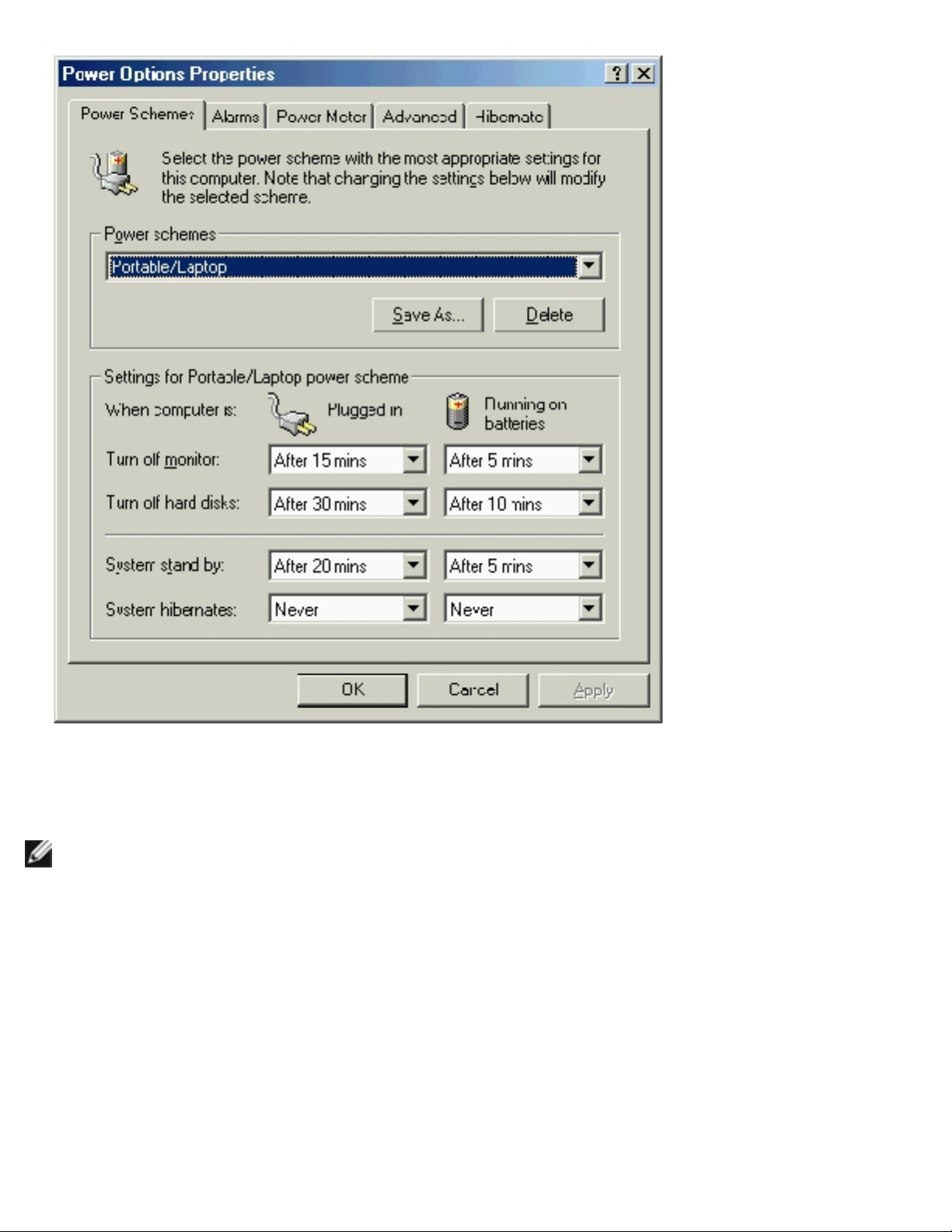
Power Options Properties
file:///I|/SERVICE%20MANUALS/DELL%20MANUALS/LAP..._checked%20ok/Inspiron/2100/2100%20SM/power.htm (2 of 9)6/21/2004 12:43:35 AM
Page 18

Power Conservation : Dell Inspiron 2100
To access the Microsoft® Windows® Power Options Properties window:
1. Click the Start button, point to Settings, and click Control Panel.
2. Double-click the Power Options icon.
The Power schemes pull-down menu displays the selected preset power scheme:
● Portable/Laptop (default)
● Home/Office
● Always On
● Presentation (Windows 2000 only)
● Minimal Power Management (Windows 2000 only)
● Max Battery (Windows 2000 only)
HINT: Dell recommends that you continue to use the Portable/Laptop power scheme to
maximize battery power conservation.
Each preset power scheme has different time-out settings for putting the computer into standby mode,
turning off the display, and turning off the hard drive.
file:///I|/SERVICE%20MANUALS/DELL%20MANUALS/LAP..._checked%20ok/Inspiron/2100/2100%20SM/power.htm (3 of 9)6/21/2004 12:43:35 AM
Page 19
Power Conservation : Dell Inspiron 2100
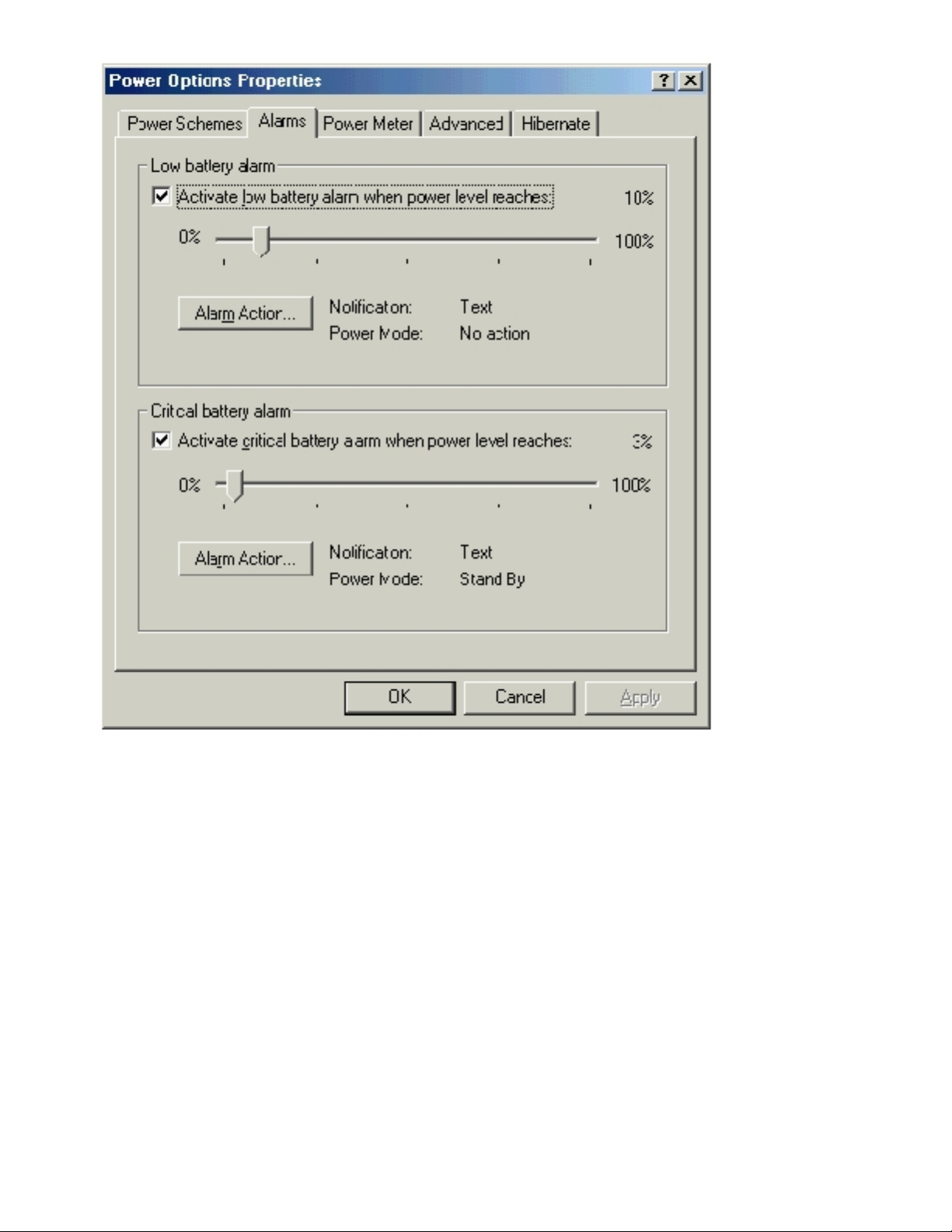
Alarms Tab
HINT: To enable audible alarms, click each Alarm Action button and select Sound
alarm.
The Low battery alarm and Critical battery alarm settings alert you with a message when the
battery charge falls below a certain percentage. When you receive your computer, the Low battery
alarm and Critical battery alarm check boxes are selected. Dell recommends that you continue to
use these defaults.
file:///I|/SERVICE%20MANUALS/DELL%20MANUALS/LAP..._checked%20ok/Inspiron/2100/2100%20SM/power.htm (4 of 9)6/21/2004 12:43:35 AM
Page 20
Power Conservation : Dell Inspiron 2100
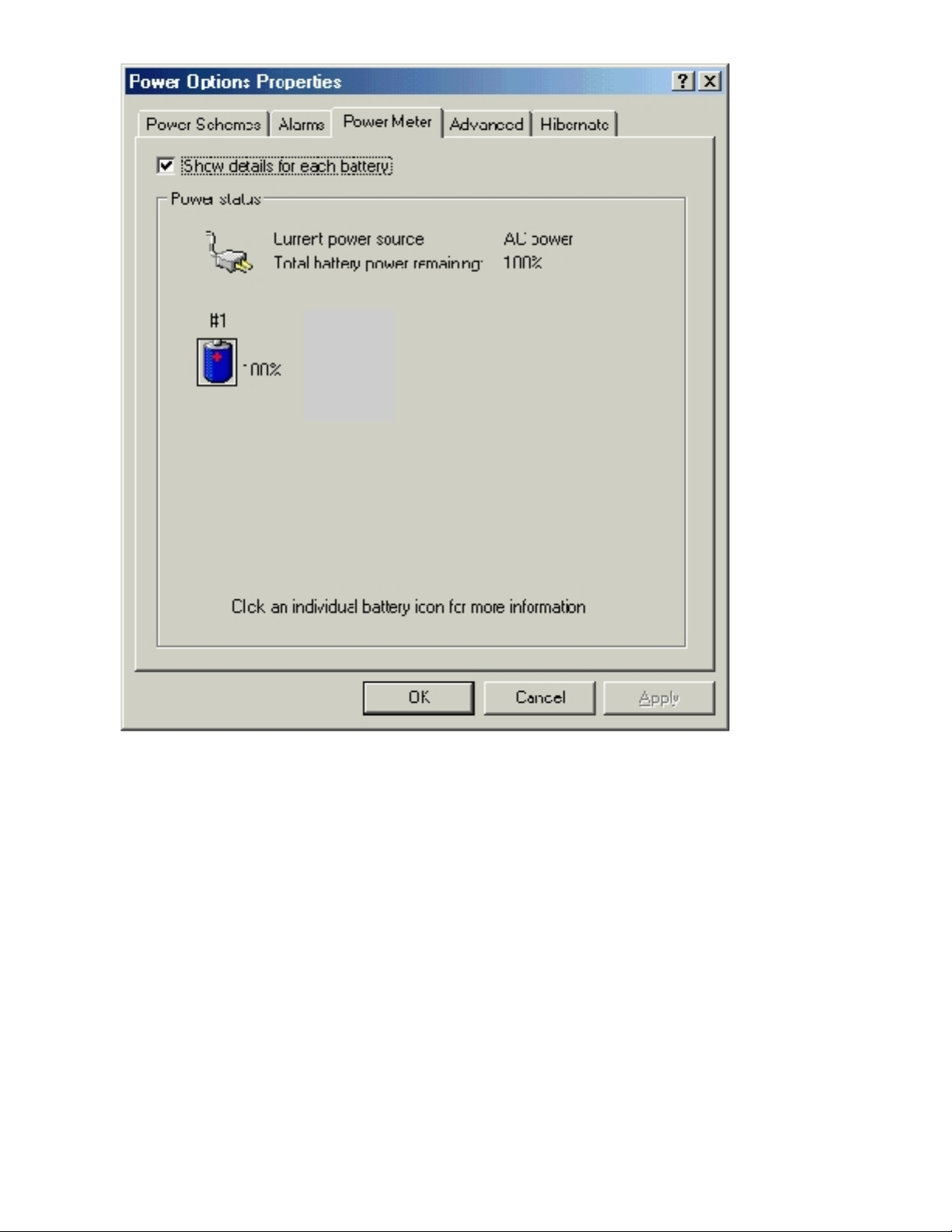
Power Meter Tab
The Power Meter tab displays the current power source and amount of battery charge remaining.
file:///I|/SERVICE%20MANUALS/DELL%20MANUALS/LAP..._checked%20ok/Inspiron/2100/2100%20SM/power.htm (5 of 9)6/21/2004 12:43:35 AM
Page 21
Power Conservation : Dell Inspiron 2100
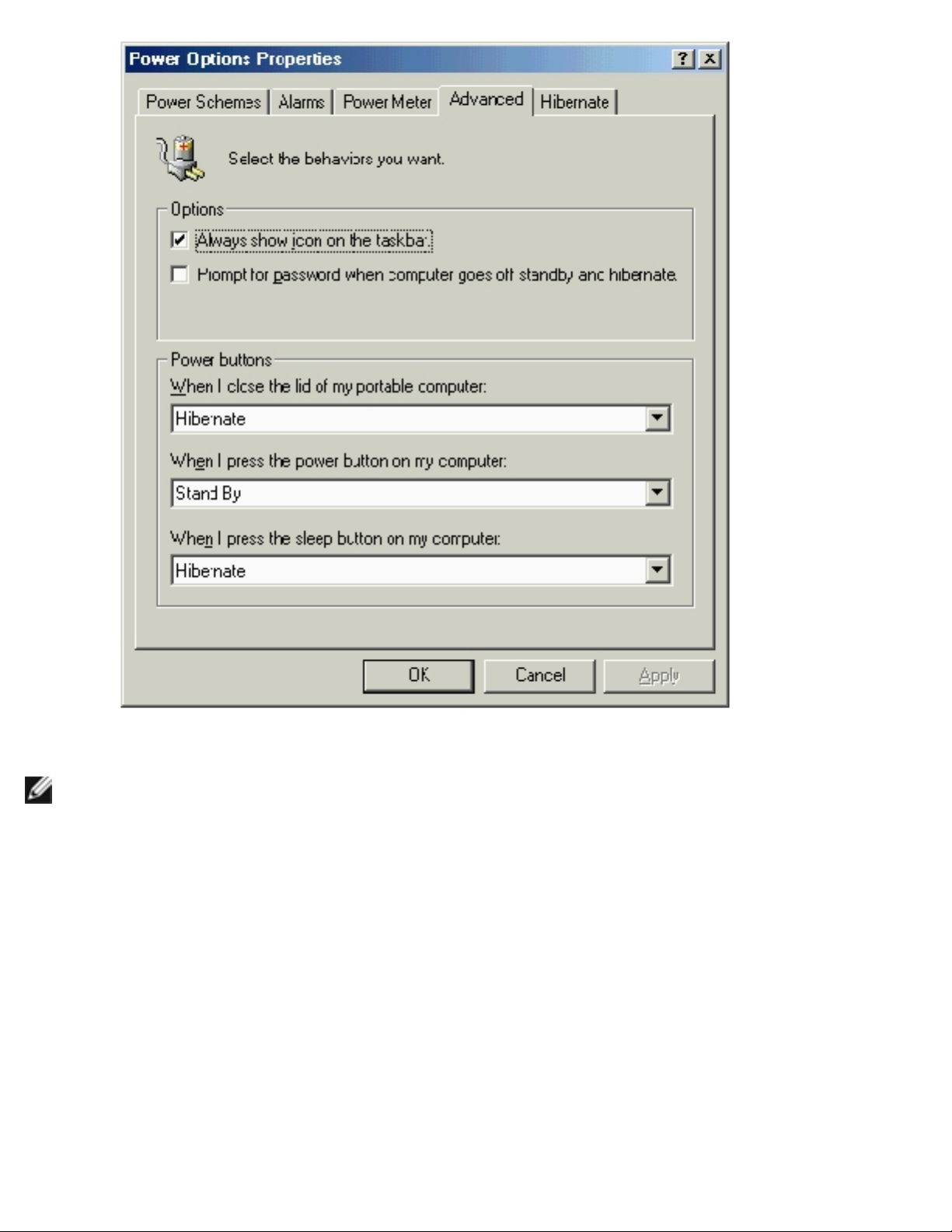
Advanced Tab
The Advanced tab allows you to:
● Set icon and standby password options.
● Program the following functions:
❍ Activate standby mode (the default when you close the display).
❍ Activate hibernate mode (the default for the power button).
❍ Shut down Windows and turn off the computer.
❍ No action (None).
file:///I|/SERVICE%20MANUALS/DELL%20MANUALS/LAP..._checked%20ok/Inspiron/2100/2100%20SM/power.htm (6 of 9)6/21/2004 12:43:35 AM
Page 22
Power Conservation : Dell Inspiron 2100
HINT: If you are going to connect your computer to a port replicator, click None when you
program the display-close option. This setting ensures that your computer does not enter
standby mode or hibernate mode when you close (lower) the display.
To program these functions, click an option from the corresponding pull- down menu, and then click
OK.
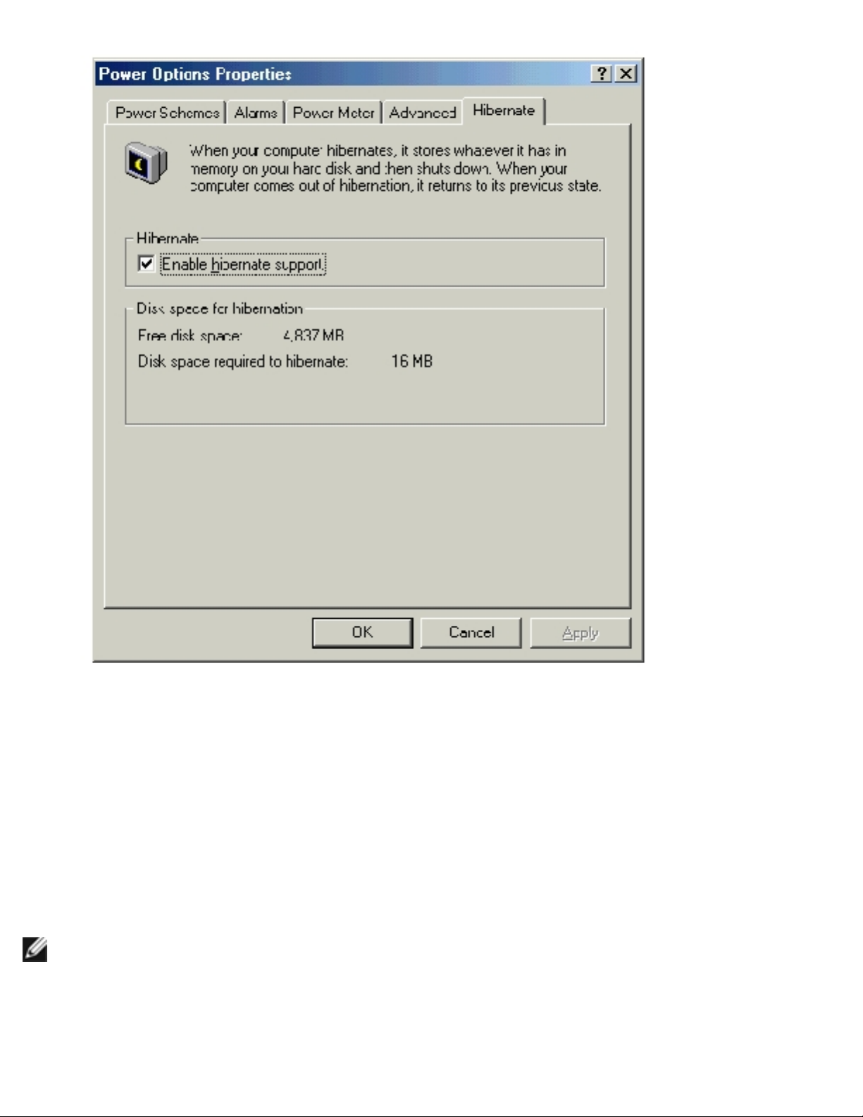
Hibernate Tab
The Hibernate tab lets you enable hibernate mode by clicking the Enable hibernate support check
box.
file:///I|/SERVICE%20MANUALS/DELL%20MANUALS/LAP..._checked%20ok/Inspiron/2100/2100%20SM/power.htm (7 of 9)6/21/2004 12:43:35 AM
Page 23
Power Conservation : Dell Inspiron 2100
Intel® SpeedStep™ Tab
If your computer has a Mobile Intel Pentium® III processor, the Power Options Properties window
includes the Intel® SpeedStep™ tab.
To change the Intel SpeedStep options, click the Advanced button and then click one of the following
options:
● Disable Intel SpeedStep technology control
HINT: If you disable Intel SpeedStep, the processor always operates at its maximum
speed.
● Remove flag icon
● Disable audio notification when performance changes
file:///I|/SERVICE%20MANUALS/DELL%20MANUALS/LAP..._checked%20ok/Inspiron/2100/2100%20SM/power.htm (8 of 9)6/21/2004 12:43:35 AM
Page 24

Power Conservation : Dell Inspiron 2100
Click Apply to accept any changes, and then click OK to close the Intel SpeedStep technology
window.
Back to Contents Page
file:///I|/SERVICE%20MANUALS/DELL%20MANUALS/LAP..._checked%20ok/Inspiron/2100/2100%20SM/power.htm (9 of 9)6/21/2004 12:43:35 AM
Page 25
Solving Problems : Dell Inspiron 2100
Back to Contents Page
Solving Problems
Dell™ Inspiron™ 2100
Accessing Help Files
Power Problems
Start-Up Error Messages
Video and Display Problems
Sound and Speaker Problems
Printer Problems
Modem Problems
Scanner Problems
Touch Pad Problems
External Keyboard Problems
Unexpected Characters
Drive Problems
Network Problems
Windows Error Messages
General Program Problems
Internet Connection Problems
E-Mail Problems
If Your Computer Gets Wet
If You Drop or Damage Your Computer
Resolving Other Technical Problems
HINT: If you have a problem with an external device, see the device documentation or contact
the manufacturer.
Accessing Help Files
To access the Tell Me How help file
1. Click the Start button, point to Programs—>User's Guides, and then click Tell Me How.
To access Microsoft® Windows® 2000 Help
1. Click the Start button and then click Help.
2. Click the Search tab.
3. Type a word or phrase that describes your problem and then click List Topics.
4. Click the topic that describes your problem and then click Display.
5. Follow the instructions shown on the screen.
file:///I|/SERVICE%20MANUALS/DELL%20MANUALS/LAP...hecked%20ok/Inspiron/2100/2100%20SM/solving.htm (1 of 14)6/21/2004 12:43:37 AM
Page 26

Solving Problems : Dell Inspiron 2100
To access Windows Me Help
1. Click the Start button and then click Help.
2. Type a word or phrase that describes your problem in the Search box and then click Go.
3. Click the topic that describes your problem and then click Display.
4. Follow the instructions shown on the screen.
Power Problems
HINT: See the Tell Me How help file for information on standby
mode.
Check the power light— When the power light is on, the computer has power. If the power light is
off, press the power button.
Check the battery— If you are using a battery to power your computer, the battery charge may be
depleted. Connect the computer to an electrical outlet using the AC adapter, and turn on the
computer.
Test the electrical outlet— Ensure that the electrical outlet is working by testing it with another
device, such as a lamp.
Check the AC adapter— Be sure that the power cable is firmly inserted into the electrical outlet
and the green light on the AC adapter is on.
Connect the computer directly to an electrical outlet— Bypass power protection devices, power
strips, and the extension cable to verify that the computer turns on.
Check for interference— Electrical appliances on the same circuit or operating near the computer
can cause interference. Other causes of interference: power extension cables, too many devices on a
power strip, or multiple power strips connected to the same electrical outlet.
Adjust the power properties— See the Tell Me How help file or search for the keyword standby in
Windows Help.
Start-Up Error Messages
Operating system not found— Contact Dell for technical assistance. See "Contacting Dell" in the
Dell Solutions Guide for the correct contact information.
file:///I|/SERVICE%20MANUALS/DELL%20MANUALS/LAP...hecked%20ok/Inspiron/2100/2100%20SM/solving.htm (2 of 14)6/21/2004 12:43:37 AM
Page 27
Solving Problems : Dell Inspiron 2100
Insert bootable media— The operating system is trying to boot to a nonbootable floppy disk or
CD. Insert a bootable floppy disk or CD.
Non-system disk error— A floppy disk is in the floppy drive. Remove the floppy disk and restart
the computer.
Video and Display Problems
If the display is blank
Check the power light— When the power light is on, the computer has power. If the power light is
off, press the power button.
Check the battery— If you are using a battery to power your computer, the battery charge may be
depleted. Connect the computer to an electrical outlet using the AC adapter, and turn on the
computer.
Test the electrical outlet— Ensure that the electrical outlet is working by testing it with another
device, such as a lamp.
Check the AC adapter— Be sure that the power cable is firmly inserted into the electrical outlet
and the green light on the AC adapter is on.
Adjust the power properties— Search for the keyword standby in Windows Help.
If the display is difficult to read
Adjust the brightness— See the Tell Me How help file for instructions on adjusting the brightness.
Move the subwoofer away from the computer or monitor— If your external speaker system
includes a subwoofer, ensure that the subwoofer is at least 60 cm (2 ft) away from the computer or
external monitor.
Eliminate possible interference— Turn off nearby fans, fluorescent lights, or halogen lamps to
check for interference.
Rotate the computer to face a different direction— Eliminate sunlight glare, which can cause
poor picture quality.
Restore the recommended settings— Restore the original resolution and refresh rate settings.
See the
Tell Me How help file for instructions.
file:///I|/SERVICE%20MANUALS/DELL%20MANUALS/LAP...hecked%20ok/Inspiron/2100/2100%20SM/solving.htm (3 of 14)6/21/2004 12:43:37 AM
Page 28
Solving Problems : Dell Inspiron 2100
Adjust the Windows display settings
1. Click the Start button, point to Settings, and then click Control Panel. (In Windows 2000,
double-click Control Panel.)
2. Double-click the Display icon and then click the Settings tab.
3. Try different settings for Colors and Screen area.
Sound and Speaker Problems
Integrated Speakers
Adjust the Windows volume control— Double-click the yellow speaker icon in the lower-right
corner of your screen. Be sure that the volume is turned up and that the sound is not muted.
Check the volume control buttons— Press <Fn><F5> to increase the volume, or press
<Fn><F6> to decrease the volume.
Reinstall the sound (audio) driver— See "Installing Drivers and Utilities."
External Speakers
HINT: The volume control in some MP3 players overrides the Windows volume setting. If you
have been listening to MP3 songs, make sure that you did not turn the player volume down or
off.
Verify the speaker cable connections— Ensure that the speakers are connected as shown on the
setup diagram supplied with the speakers.
Test the electrical outlet— Ensure that the electrical outlet is working by testing it with another
device, such as a lamp.
Ensure that the speakers are turned on— See the setup diagram supplied with the speakers.
Adjust the speaker controls— Adjust the volume, bass, or treble controls to eliminate distortion.
Adjust the Windows volume control— Double-click the yellow speaker icon in the lower-right
corner of your screen. Be sure that the volume is turned up and that the sound is not muted.
Test the speakers— Plug the speaker audio cable into the headphone connector on the side of the
computer. Ensure that the headphone volume control is turned up. Play a music CD.
Run the speaker self-test— Some speaker systems have a self-test button on the subwoofer. See
the speaker documentation for self-test instructions.
file:///I|/SERVICE%20MANUALS/DELL%20MANUALS/LAP...hecked%20ok/Inspiron/2100/2100%20SM/solving.htm (4 of 14)6/21/2004 12:43:37 AM
Page 29

Solving Problems : Dell Inspiron 2100
Move the subwoofer away from the computer or monitor— If your external speaker system
includes a subwoofer, ensure that the subwoofer is at least 60 cm (2 ft) away from the computer or
external monitor.
Eliminate possible interference— Turn off nearby fans, fluorescent lights, or halogen lamps to
check for interference.
Reinstall the sound (audio) driver— See "Installing Drivers and Utilities."
Printer Problems
If you cannot print to a parallel port printer
Verify the printer cable connections— Ensure that the printer cable is connected (see
"Connecting a Printer" in Chapter 1 of the Dell Solutions Guide that came with your computer).
Test the electrical outlet— Ensure that the electrical outlet is working by testing it with another
device, such as a lamp.
Ensure that the printer is turned on— See the documentation supplied with the printer.
Verify that the printer is recognized by Windows
1. Click the Start button, point to Settings, and then click Printers.
If the printer is listed, right-click the printer icon, click Properties, and then select the Details
tab.
2. Ensure that the Print to the following port: setting is LPT1 (Printer Port).
Reinstall the printer driver— See "Installing the Printer Driver" in Chapter 1 of the Dell Solutions
Guide.
If you cannot print to a USB printer
Verify the printer cable connections— Ensure that the printer cable is connected (see
"Connecting a Printer" in Chapter 1 of the Dell Solutions Guide that came with your computer).
Test the electrical outlet— Ensure that the electrical outlet is working by testing it with another
device, such as a lamp.
Ensure that the printer is turned on— See the documentation supplied with the printer.
file:///I|/SERVICE%20MANUALS/DELL%20MANUALS/LAP...hecked%20ok/Inspiron/2100/2100%20SM/solving.htm (5 of 14)6/21/2004 12:43:37 AM
Page 30

Solving Problems : Dell Inspiron 2100
Verify that the printer is recognized by Windows
1. Click the Start button, point to Settings, and then click Printers.
If the printer is listed, right-click the printer icon, click Properties, and then select the Details
tab.
2. Ensure that the Print to the following port: setting is USB.
Reinstall the printer driver— See "Installing the Printer Driver" in Chapter 1 of the Dell
Solutions Guide.
Modem Problems
NOTICE: Connect the modem to an analog telephone wall jack only. Connecting the modem to
a digital telephone network damages the modem.
Check the telephone jack— Disconnect the telephone line from the modem and connect it to a
telephone. Listen for a dial tone.
Connect the modem directly to the telephone wall jack— If you have other telephone devices
sharing the line, such as an answering machine, fax machine, surge protector, or line splitter, then
bypass them and connect the modem directly to the telephone wall jack with the telephone line.
Check the connection— Verify that the telephone line is connected to the modem.
Check the telephone line— Try using a different telephone line. If you are using a line that is 3 m
(10 ft) or more in length, try a shorter one.
Run the modem diagnostics— Click the Start button, point to Programs—>
Accessories—>Communications, and then click Dell Internal Modem Diagnostic Tool.
Scanner Problems
Check the power cable connection— Ensure that the scanner power cable is firmly connected to a
working electrical power source and that the scanner is turned on.
Check the scanner cable connection— Ensure that the scanner cable is firmly connected to the
computer and to the scanner.
file:///I|/SERVICE%20MANUALS/DELL%20MANUALS/LAP...hecked%20ok/Inspiron/2100/2100%20SM/solving.htm (6 of 14)6/21/2004 12:43:37 AM
Page 31

Solving Problems : Dell Inspiron 2100
Unlock the scanner— Ensure that your scanner is unlocked if it has a locking tab or button.
Reinstall the scanner driver— See the scanner documentation for instructions.
Touch Pad Problems
Check the touch pad settings— Click the Start button, point to Settings, click Control Panel
(double-click Control Panel in Windows 2000), and then double-click the Mouse icon. Try adjusting
the settings.
External Keyboard Problems
Disconnect the keyboard cable— Shut down the computer. Disconnect the keyboard cable and
check the cable connector for bent or broken pins.
Unexpected Characters
Disable the numeric keypad— Press the <Num Lk> key to disable the numeric keypad. Verify that
the numbers lock light is not lit.
Drive Problems
If you cannot save a file to a floppy disk
HINT: For information on saving files to a floppy disk, see the Tell Me How help
file.
Ensure that the external media bay is connected— Check the external media bay cable and
make sure that it is connected to the floppy drive and to the connector on the back of the computer.
file:///I|/SERVICE%20MANUALS/DELL%20MANUALS/LAP...hecked%20ok/Inspiron/2100/2100%20SM/solving.htm (7 of 14)6/21/2004 12:43:37 AM
Page 32

Solving Problems : Dell Inspiron 2100
Ensure that Windows recognizes the drive— Double-click the My Computer icon. If the floppy
drive is not listed, perform a full scan with your antivirus software to check for and remove viruses.
Viruses can sometimes prevent Windows from recognizing the drive.
Cannot save files to a floppy disk— Ensure that the floppy disk is not full or write-protected
(locked). See the following illustration.
Test the drive with another floppy disk— Insert another floppy disk to eliminate the possibility
that the original floppy disk is defective.
If you cannot play a music CD or install a program from a
CD
HINT: High-speed CD drive vibration is normal and may cause noise. This noise does not
indicate a defect in the drive or the CD.
Ensure that the external media bay is connected— Check the external media bay cable and
make sure that it is connected to the CD drive and to the connector on the back of the computer.
Ensure that Windows recognizes the drive— Double-click the My Computer icon. If the CD
drive is not listed, perform a full scan with your antivirus software to check for and remove viruses.
Viruses can sometimes prevent Windows from recognizing the drive.
Test the drive with another CD— Insert another CD to eliminate the possibility that the original
CD is defective.
Clean the disc— See the Tell Me How help file for instructions.
file:///I|/SERVICE%20MANUALS/DELL%20MANUALS/LAP...hecked%20ok/Inspiron/2100/2100%20SM/solving.htm (8 of 14)6/21/2004 12:43:37 AM
Page 33

Solving Problems : Dell Inspiron 2100
Adjust the Windows volume control— Double-click the yellow speaker icon in the lower-right
corner of your screen. Be sure that the volume is turned up and that the sound is not muted.
If you cannot play a DVD movie
HINT: Because of different worldwide file types, not all DVD titles work in all DVD
drives.
Ensure that the external media bay is connected— Check the external media bay cable and
make sure that it is connected to the DVD drive and to the connector on the back of the computer.
Ensure that Windows recognizes the drive— Double-click the My Computer icon. If the DVD
drive is not listed, perform a full scan with your antivirus software to check for and remove viruses.
Viruses can sometimes prevent Windows from recognizing the drive.
Test the drive with another DVD— Insert another DVD to eliminate the possibility that the
original DVD is defective.
Clean the disc— See the Tell Me How help file for instructions.
If the CD-RW drive stops writing
HINT: If you must disable standby mode to write to a CD-RW drive, remember to enable
standby mode again when you finish writing the CD.
Disable standby mode in Windows before writing to a CD-RW disk— Search for the keyword
standby in
Windows Help.
Change the write speed to a slower rate— The CD-RW drive must receive a steady stream of
data when writing. If the stream is interrupted, an error occurs. Closing all programs before writing
to the CD-RW may also alleviate the problem.
If you have a hard drive problem
file:///I|/SERVICE%20MANUALS/DELL%20MANUALS/LAP...hecked%20ok/Inspiron/2100/2100%20SM/solving.htm (9 of 14)6/21/2004 12:43:37 AM
Page 34

Solving Problems : Dell Inspiron 2100
Check the hard drive for errors
Windows Millennium Edition (Me):
Click the Start button, point to Programs—> Accessories—> System Tools, and then click
ScanDisk.
Windows 2000:
1. Double-click the My Computer icon.
2. Right-click the Local Disk icon and then click Properties.
3. Click the Tools tab.
4. Click Check Now.
Network Problems
Check the network cable connector— Ensure that the network cable connector is firmly
connected to the connector on the computer and the network wall jack.
Restart the computer— Try to log on to the network again.
Contact your network administrator— Verify that your network settings are correct and that the
network is functioning.
Windows Error Messages
x:\ is not accessible. The device is not ready— Insert a disk into the drive and try again.
A filename cannot contain any of the following characters: \ / : * ? " < > |— Do not use
these characters in filenames.
Not enough memory or resources. Close some programs and try again— You have too many
programs open. Close all windows and open the program that you want to use.
The file being copied is too large for the destination drive— The file that you are trying to
copy is too large to fit on the disk, or the disk is too full. Try copying the file to a different disk or
use a larger capacity disk.
file:///I|/SERVICE%20MANUALS/DELL%20MANUALS/LA...ecked%20ok/Inspiron/2100/2100%20SM/solving.htm (10 of 14)6/21/2004 12:43:37 AM
Page 35

Solving Problems : Dell Inspiron 2100
A required .DLL file was not found— The program that you are trying to open is missing an
essential file. To remove and then reinstall the program:
Windows Me:
1. Click the Start button, point to Settings, and then click Control Panel.
2. Double-click the Add/Remove Programs icon.
3. Select the program that you want to remove.
4. Click Add/Remove and follow the prompts on the screen.
5. See the program documentation for installation instructions.
Windows 2000:
1. Click the Start button, point to Settings, and then double-click Control Panel.
2. Double-click the Add/Remove Programs icon.
3. Select the program that you want to remove.
4. Click Change/Remove and follow the prompts on the screen.
5. See the program documentation for installation instructions.
General Program Problems
A program crashes
See the software documentation— Many software manufacturers maintain websites with
information that may help you to solve the problem.
A program stops responding
Press <Ctrl><Alt><Del>— In the Close Program window, select the program that is no longer
responding. Then click End Task.
A solid blue screen appears
Turn the computer off— If the computer does not respond to a keystroke or a proper shutdown,
press the power button until the computer turns off. Press the power button again to restart the
computer. The solid blue screen appears because you were not able to perform a proper Windows
shutdown. ScanDisk will automatically run during the start-up process. Follow the instructions on the
screen.
file:///I|/SERVICE%20MANUALS/DELL%20MANUALS/LA...ecked%20ok/Inspiron/2100/2100%20SM/solving.htm (11 of 14)6/21/2004 12:43:37 AM
Page 36

Solving Problems : Dell Inspiron 2100
Internet Connection Problems
Review "Modem Problems"— See "Modem Problems."
Turn off call waiting (catch-phone)— See your telephone directory for instructions on
deactivating this feature. Then adjust the dial-up networking connection properties:
1. Click the Start button, point to Settings, and then click Control Panel. (In Windows 2000,
double-click Control Panel.)
2. Double-click the Modems icon.
3. In the Modems Properties window, click Dialing Properties.
4. Ensure that To disable call waiting, dial: is checked, and then select the proper code
according to the information in your telephone directory.
5. Click Apply and then click OK.
6. Close the Modems Properties window.
7. Close the Control Panel window.
E-Mail Problems
Ensure that you are connected to the Internet— With the Outlook Express e-mail program
open, click File. If Work Offline has a check next to it, click the check to remove it and connect to
the Internet.
If Your Computer Gets Wet
CAUTION: Perform this procedure only after you are certain that it is safe to do so. If
the computer is connected to an electrical outlet, Dell recommends that you turn off
AC power at the circuit breaker before attempting to remove the power cables from
the electrical outlet. Use the utmost caution when removing wet cables from a live
power source.
1. Turn off the computer, disconnect the AC adapter from the computer, and disconnect the AC
adapter from the electrical outlet.
2. Turn off any attached external devices, and disconnect them from their power sources and then
from the computer.
file:///I|/SERVICE%20MANUALS/DELL%20MANUALS/LA...ecked%20ok/Inspiron/2100/2100%20SM/solving.htm (12 of 14)6/21/2004 12:43:37 AM
Page 37

Solving Problems : Dell Inspiron 2100
3. Disconnect the external media bay.
4. Ground yourself by touching one of the metal connectors on the back of the computer.
5. Remove the PC Card, and put it in a safe place to dry.
6. Remove the battery.
7. Wipe off the battery and put it in a safe place to dry.
8. Remove the hard drive.
9. Open the display, and place the computer right-side up across two books or similar props to let
air circulate all around it. Let the computer dry for at least 24 hours in a dry area at room
temperature.
NOTICE: Do not use artificial means, such as a hair dryer or a fan, to speed up the drying
process.
CAUTION: To help prevent electrical shock, verify that the computer is thoroughly
dry before continuing with the remainder of this procedure.
10. Ground yourself by touching one of the metal connectors on the back of the computer.
11. Replace the hard drive and screw.
12. Replace the PC Card.
13. Replace the battery.
14. Turn on the computer and verify that it is working properly.
If the computer does not turn on, or if you cannot identify the damaged components, contact Dell for
technical assistance. See "Contacting Dell" in the Dell Solutions Guide for information on contacting
Dell.
If You Drop or Damage Your Computer
1. Save and close any open files, exit any open application programs, and shut down the
computer.
2. Disconnect the AC adapter from the computer, and disconnect the AC adapter from the
electrical outlet.
3. Turn off any attached external devices, and disconnect them from their power sources and then
from the computer.
4. Remove and reinstall the battery.
file:///I|/SERVICE%20MANUALS/DELL%20MANUALS/LA...ecked%20ok/Inspiron/2100/2100%20SM/solving.htm (13 of 14)6/21/2004 12:43:37 AM
Page 38

Solving Problems : Dell Inspiron 2100
5. Turn on the computer.
If the computer does not turn on, or if you cannot identify the damaged components, call Dell for
technical assistance. See "Contacting Dell" in the Dell Solutions Guide for information on contacting
Dell
Resolving Other Technical Problems
Go to the Dell support website— Go to http://support.dell.com for help with general usage,
installation, and troubleshooting questions.
E-mail Dell— Go to http://support.dell.com and then click E-Mail Dell in the Communicate list.
Send an e-mail message to Dell about your problem; you can expect to receive an e-mail message
from Dell within hours.
Contact Dell— If you cannot solve your problem using the Dell support website or e-mail service,
contact Dell for technical assistance. See "Contacting Dell" in the Dell Solutions Guide for information
on contacting Dell.
Back to Contents Page
file:///I|/SERVICE%20MANUALS/DELL%20MANUALS/LA...ecked%20ok/Inspiron/2100/2100%20SM/solving.htm (14 of 14)6/21/2004 12:43:37 AM
Page 39

System Specifications : Dell Inspiron 2100
Back to Contents Page
System Specifications
Dell™ Inspiron™ 2100
Specifications
Specifications
Microprocessor
Microprocessor types Intel® mobile microprocessor
Internal cache 256 KB
External bus frequency 100 MHz
Math coprocessor internal to the microprocessor
System Information
System chip set Intel Mobile 440BX PCI
Data bus width 64 bits
DRAM bus width 64 bits
Microprocessor address bus width 32 bits
PC Card
CardBus controller Texas Instruments TI1410 CardBus controller
PC Card connectors one (supports one Type I or Type II card, including ZV cards)
Cards supported 3.3 V and 5 V
PC Card connector size 68 pins
Data width (maximum) PCMCIA 16 bits
CardBus 32 bits
file:///I|/SERVICE%20MANUALS/DELL%20MANUALS/LAP..._checked%20ok/Inspiron/2100/2100%20SM/specs.htm (1 of 6)6/21/2004 12:43:38 AM
Page 40

System Specifications : Dell Inspiron 2100
Memory
Architecture SDRAM
Memory module socket 144-pin industrial standard SODIMM socket
Memory module capacities and type 64, 128, and 256 MB
Memory type 3.3-V SODIMM
Standard memory one 64-MB memory module
Maximum memory 256 MB
Memory access time: clock speed 100 MHz
Ports and Connectors
Parallel 25-hole connector; unidirectional, bidirectional, or ECP
IDE IDE connector for the external media bay
Video VGA connector
PS/2 keyboard/mouse 6-pin mini-DIN connector
Audio microphone connector, headphone/speakers connector
USB one 4-pin USB-compliant connector
Docking connector for the Dell™ advanced port replicator (APR)
Modem RJ-11 connector
Network RJ-45 connector
Video
Data bus AGP
Video controller ATI Mobility M
Video memory 4 MB
Audio
Audio type Sound Blaster (software emulation capable)
file:///I|/SERVICE%20MANUALS/DELL%20MANUALS/LAP..._checked%20ok/Inspiron/2100/2100%20SM/specs.htm (2 of 6)6/21/2004 12:43:38 AM
Page 41

System Specifications : Dell Inspiron 2100
Audio controller Crystal CS4281 + CS4297A (AC97 CODEC)
Stereo conversion 20-bit analog-to-digital
18-bit digital-to-analog
Interfaces:
Internal PCI bus/AC97
External microphone connector, headphone/speakers connector
Speakers 4-ohm speakers
Internal speaker amplifier 1.75-W
Volume controls key combinations, volume buttons, program menus
Display
Type XGA, active-matrix color (TFT)
Dimensions:
Height 184.3 mm (7.25 inches)
Width 245.76 mm (9.67 inches)
Diagonal 307.3 mm (12.1 inches)
Maximum resolution 1024 x 768
Response time (typical) 10-ms rise (maximum), 30-ms fall (maximum)
Operating angle 0º (closed) to 180º
Viewing angle:
Horizontal ± 45º
Vertical + 15º, – 30º
Dot pitch 0.24 mm
Power consumption:
Panel (typical) 891 mW
Backlight 3.3 W
Controls brightness can be controlled through key combinations
Keyboard
Number of keys 84 (U.S. and Canada); 87 (Japan)
file:///I|/SERVICE%20MANUALS/DELL%20MANUALS/LAP..._checked%20ok/Inspiron/2100/2100%20SM/specs.htm (3 of 6)6/21/2004 12:43:38 AM
Page 42

System Specifications : Dell Inspiron 2100
Key travel 2.5 ± 0.2 mm (0.098 inch ± 0.08 inch)
Key spacing 118 mm (0.70 inch)
Touch Pad
Interface PS/2 compatible
X/Y position resolution (graphics table mode)
minimum 20 points/mm (500 points/inch)
Size:
Thickness 0.69 ± 0.15 mm (0.027 inch ± 0.006 inch) printed-
circuit board (PCB) thickness
Width 64.88 mm (2.55-inch) sensor-active area
Height 48.88-mm (1.92-inch) rectangle
Weight 6.0 ± 0.5 g (0.21 ounce)
Power:
Supply voltage 5 V ± 0.5 VDC
Supply current 4.0 mA (nominal operation)
ESD 15 kV applied to front surface
Battery
Type lithium ion
Dimensions:
Depth 57.25 mm (2.25 inches)
Height 12.7 mm (0.5 inch)
Width 262.49 mm (10.33 inches)
Weight 220 g (4 cell)
293 g (6 cell)
Voltage 14.8 VDC (4 cell)
11.10 VDC (6 cell)
Capacity 23 WH (4 cell)
34 WH (6 cell)
Charge time (approximate):
file:///I|/SERVICE%20MANUALS/DELL%20MANUALS/LAP..._checked%20ok/Inspiron/2100/2100%20SM/specs.htm (4 of 6)6/21/2004 12:43:38 AM
Page 43

System Specifications : Dell Inspiron 2100
Computer on about 1.75 hours (4 cell)
about 2.0 hours (6 cell)
Computer off about 1.5 hours (4 cell)
about 1.75 hours (6 cell)
Life span (approximate) 300 discharge/charge cycles before the battery will be operating at
about 80% of the original capacity
Temperature range:
Charge 0º to 45ºC (32º to 113ºF)
Discharge 0º to 60ºC (32º to 140ºF)
Storage –20º to 35ºC (–4º to 95ºF) for up to a year
–20º to 50ºC (–4º to 122ºF) for less than one month
AC Adapter
Input voltage 100 to 240 VAC
Input current (maximum) 1.5 A
Input frequency 50 to 60 Hz
Output current 2.64 A (maximum)
Rated output voltage 19.0 VDC
Dimensions:
Height 29 mm (1.14 inches)
Width 46.3 mm (1.82 inches)
Depth 108 mm (4.25 inches)
Weight (with cables) 355 g (0.78 lb)
Temperature range:
Operating 0º to 40ºC (32º to 104ºF)
Storage –20º to 60ºC (–4º to 140ºF)
Environmental (Computer)
Temperature range:
Operating 5º to 35ºC (41º to 95ºF)
Storage –20º to 60ºC (–4º to 140ºF)
file:///I|/SERVICE%20MANUALS/DELL%20MANUALS/LAP..._checked%20ok/Inspiron/2100/2100%20SM/specs.htm (5 of 6)6/21/2004 12:43:38 AM
Page 44

System Specifications : Dell Inspiron 2100
Relative humidity (maximum):
Operating 20% to 80% (noncondensing)
Storage 8% to 90% (noncondensing)
Maximum vibration:
Operating 0.9 GRMS using a random-vibration spectrum that simulates user
environment
Storage 1.3 GRMS using a random-vibration spectrum that simulates air/
truck shipment
Maximum shock:
Operating 152.4 cm/sec (60 inches/sec) (equal to a half-sine pulse width of 2
ms)
Storage 203.2 cm/sec (80 inches/sec) (equal to a half-sine pulse width of 2
ms)
Altitude:
Operating –18 to 3048 m (–59 to 10,000 ft)
Storage –18 to 10,600 m (–59 to 35,000 ft)
Back to Contents Page
file:///I|/SERVICE%20MANUALS/DELL%20MANUALS/LAP..._checked%20ok/Inspiron/2100/2100%20SM/specs.htm (6 of 6)6/21/2004 12:43:38 AM
Page 45

Drivers and Utilities : Dell Inspiron 2100
Back to Contents Page
Drivers and Utilities
Dell™ Inspiron™ 2100
Overview
Installing Drivers and Utilities
Overview
All of your computer's utilities and all drivers for Dell-installed devices are operative when you receive
the computer—no further installation or configuration is needed. However, if you ever need to reinstall
any of the drivers or utilities, use the Dell Drivers and Utilities CD that you received with your
computer. Your Drivers and Utilities CD also contains the Dell Diagnostics and online documentation for
your computer.
You can also access system tools and documentation from Dell's support website at http://support.
dell.com. Select your country by clicking on the map that appears. At the Welcome to support.dell.
com page, enter your computer information to access the help tools and information available for your
computer.
Installing Drivers and Utilities
1. Save your work in all open programs.
2. Insert the Drivers and Utilities CD into the CD or DVD drive.
In most cases, the CD should start running automatically. If it does not, start Windows®
Explorer, click your CD drive directory to display the CD contents, and then click the Start.htm
file.
3. Click a language button to select your preferred user interface language.
The System Software screen appears, displaying a list of operating systems (Software by
Operating System) and an All Software category.
4. Under Software by Operating System, click your operating system to display a list of drivers,
a Utilities subdirectory, and a Documentation subdirectory.
file:///I|/SERVICE%20MANUALS/DELL%20MANUALS/LAP...ecked%20ok/Inspiron/2100/2100%20SM/driverme.htm (1 of 4)6/21/2004 12:43:38 AM
Page 46

Drivers and Utilities : Dell Inspiron 2100
5. Click the type of driver (for example, Audio) or the utility you want to install.
A link appears for the specific driver or utility used by your system.
6. Click the link to display the Languages screen.
7. Click your preferred language for the driver or utility (if available) or click Multiple.
8. At the driver information screen, do one of the following:
● Click the Install button (if present) to start the automatic installation. At the dialog box,
select Run this program from its current location and then follow the screen
prompts to complete the installation.
● If no Install button is present, automatic installation is not an option. For installation
instructions, either click the Readme link or go to the appropriate procedure below.
NOTICE: If instructed to navigate to the driver files, click the CD directory on the driver
information screen to display the files associated with that driver.
Installing the NIC Driver for Microsoft® Windows® 2000
1. Save your work and insert your Drivers and Utilities CD. You may close the CD interface (if
desired) before continuing with the procedure.
2. Click the Start button, point to Settings, and double-click Control Panel.
3. In the Control Panel, double-click the System icon.
4. In the System Properties window, click the Hardware tab.
5. Click Device Manager.
6. Double-click Network Adapters, and then right-click 3Com 3C920 Integrated Fast
Ethernet Controller (3C905C-TX Compatible).
7. Click Properties.
8. Click the Driver tab.
9. Click Update Driver.
The Update Device Driver Wizard window appears.
10. Click Next.
11. Select Display a list of all the drivers in a specific location, so you can select the driver
you want, and click Next.
12. Select Network Adapters and click Next.
file:///I|/SERVICE%20MANUALS/DELL%20MANUALS/LAP...ecked%20ok/Inspiron/2100/2100%20SM/driverme.htm (2 of 4)6/21/2004 12:43:38 AM
Page 47

Drivers and Utilities : Dell Inspiron 2100
13. Click Have Disk.
14. Type your CD drive designator (for example, d:\) and then click Browse.
15. Navigate to the Network subdirectory, double-click the Network subdirectory, double-click the
R21083 folder, and click Open.
16. At the Install From Disk dialog box, which verifies the directory you selected, click OK.
17. Verify that 3Com 3C920 Integrated Fast Ethernet Controller (3C905C-TX Compatible) is
selected, and then click Next.
18. When the Update Device Driver Wizard verifies the location of the driver, click Next.
19. When you receive the message that the software installation is complete, click Finish.
20. At the 3Com screen, click Close.
21. Remove the CD and restart the computer.
Installing the NIC Driver for Windows Millennium Edition
(Me)
1. Save your work and insert your Drivers and Utilities CD. You may close the CD interface (if
desired) before continuing with the procedure.
2. Click the Start button, point to Settings, and click Control Panel.
3. In the Control Panel, double-click the System icon.
NOTICE: To see the System icon, you may need to click View all control panel options at
the left side of the screen.
4. In the System Properties window, click the Device Manager tab.
5. Double-click Network Adapters, and then right-click 3Com 3C920 Integrated Fast
Ethernet Controller (3C905C-TX Compatible).
6. Click Properties.
7. Click the Driver tab.
8. Click Update Driver.
The Update Device Driver Wizard window appears.
9. Select Specify the location of the driver (Advanced).
10. Click Next.
11. Click to uncheck Removable Media, and click to check Specify a location.
file:///I|/SERVICE%20MANUALS/DELL%20MANUALS/LAP...ecked%20ok/Inspiron/2100/2100%20SM/driverme.htm (3 of 4)6/21/2004 12:43:38 AM
Page 48

Drivers and Utilities : Dell Inspiron 2100
12. Type your CD drive designator (for example, d:\) and the click Browse.
13. Navigate to the Network subdirectory, double-click the Network subdirectory, double-click the
R21083 folder, and click OK.
14. At the Update Device Driver dialog box, click Next.
15. Verify that 3Com 3C920 Integrated Fast Ethernet Controller (3C905C-TX Compatible) is
selected, and then click Next.
16. When the Update Device Driver Wizard verifies the location of the driver, click Next.
17. To verify and accept the name of the driver, click Next.
18. When you receive the message that the software installation is complete, click Finish.
19. When prompted to restart your computer, remove the operating system CD and click Yes.
Back to Contents Page
file:///I|/SERVICE%20MANUALS/DELL%20MANUALS/LAP...ecked%20ok/Inspiron/2100/2100%20SM/driverme.htm (4 of 4)6/21/2004 12:43:38 AM
Page 49

System Setup Program : Dell Inspiron 2100
Back to Contents Page
System Setup Program
Dell™ Inspiron™ 2100
Standard Settings
System Setup Pages
Viewing the System Setup Program Pages
Standard Settings
The system setup program contains the standard settings for your computer.
NOTICE: Unless you are an expert computer user, don't change the settings for this program.
Certain changes might make your computer work incorrectly.
System Setup Pages
HINT: To see information about a specific item, highlight the item and refer to the Help area
on the screen.
The system setup program pages display the current setup information and settings for your
computer. You can change settings that appear as white type on the screen.
● Page 1 displays system information.
● Page 2 displays basic device configuration settings.
● Page 3 displays system security and hard drive password settings.
● Page 4 displays power management settings.
● Page 5 displays the boot configuration.
● Page 6 displays setting and exit options.
file:///I|/SERVICE%20MANUALS/DELL%20MANUALS/LAP..._checked%20ok/Inspiron/2100/2100%20SM/setup.htm (1 of 2)6/21/2004 12:43:39 AM
Page 50

System Setup Program : Dell Inspiron 2100
Viewing the System Setup Program Pages
1. Turn on (or restart) your computer.
2. Press <F2> immediately.
If you wait too long and the Windows® logo appears, continue to wait until you see the Windows
desktop. Then shut down your computer and try again.
Back to Contents Page
file:///I|/SERVICE%20MANUALS/DELL%20MANUALS/LAP..._checked%20ok/Inspiron/2100/2100%20SM/setup.htm (2 of 2)6/21/2004 12:43:39 AM
Page 51

Ports and Connector Pin-Outs : Dell Inspiron 2100
Back to Contents Page
Ports and Connector Pin-Outs
Dell™ Inspiron™ 2100
Connector Locations
Parallel Connector
Docking Connector
PS/2 Connector
USB Connector
Video Connector
External Media Bay Connector
Connector Locations
Parallel Connector
Use the 25-hole parallel connector to attach a parallel device to the computer. The parallel connector is used primarily
for printers. The parallel connector transmits data in parallel format, where 8 data bits (one byte) are sent
simultaneously over eight separate lines.
The parallel connector can also be configured for compatibility with the PS/2 standard. Support for the EPP feature
improves network adapter performance (adapters connect to the computer's parallel connector and require the
appropriate software drivers from the adapter's manufacturer).
file:///I|/SERVICE%20MANUALS/DELL%20MANUALS/LAP...hecked%20ok/Inspiron/2100/2100%20SM/pinouts.htm (1 of 7)6/21/2004 12:43:41 AM
Page 52

Ports and Connector Pin-Outs : Dell Inspiron 2100
If you reconfigure your hardware, you may need pin number and signal information for the parallel connector.
Pin Signal I/O Definition
1 STB# I/O Strobe
2 D0 I/O Printer data bit 0
3 PD1 I/O Printer data bit 1
4 PD2 I/O Printer data bit 2
5 PD3 I/O Printer data bit 3
6 PD4 I/O Printer data bit 4
7 PD5 I/O Printer data bit 5
8 PD6 I/O Printer data bit 6
9 PD7 I/O Printer data bit 7
10 ACK# I Acknowledge
11 BUSY I Busy
12 PE I Paper end
13 SLCT I Select
14 AFD# O Automatic feed
15 ERR# I Error
16 INIT# O Initialize printer
17 SLIN# O Select in
18-25 N/A N/A Ground signal
Shell N/A N/A Frame ground
Docking Connector
Use this connector to attach your computer to the optional port replicator.
file:///I|/SERVICE%20MANUALS/DELL%20MANUALS/LAP...hecked%20ok/Inspiron/2100/2100%20SM/pinouts.htm (2 of 7)6/21/2004 12:43:41 AM
Page 53

Ports and Connector Pin-Outs : Dell Inspiron 2100
Pin Signal Pin Signal Pin Signal
1 5VSUS 51 -IDETN 101 PE
2 5VSUS 52 -TRK0 102 PD3
3 GND 53 OHRCN 103 SLCT
4 GND 54 GND 104 PD4
5 -SDIOW 55 OVP 105 -AFD
6 SDDREQ 56 TXP 106 PD5
7 SIORDY 57 GND 107 -ERROR
8 -SDIOR 58 TXN 108 PD6
9 IRQ15 59 +5V 109 -INIT
10 -SDDACK 60 3VSUS 110 PD7
11 SDA1 61 +5V 111 -SLIN
12 SDA2 62 3VSUS 112 COMRING
13 SDA0 63 +5V 113 -PNF
14 -SDCS3 64 -DK_DEVINS 114 -RS232PD
15 CDRST 65 +5V 115 GND
16 -SDCS1 66 -DMUTE 116 DSR1
17 SDD0 67 +5V 117 DTR1
18 SDD8 68 -PREP 118 RTS1
19 SDD1 69 +5V 119 -TXD1
20 SDD9 70 -OC1 120 CTS1
21 SDD2 71 +5V 121 -RXD1
22 SDD10 72 USBP1- 122 -RI1
23 SDD3 73 GND 123 DCD1
24 SDD11 74 USBP1+ 124 GND
25 SDD4 75 -D_RESET 125 GND
file:///I|/SERVICE%20MANUALS/DELL%20MANUALS/LAP...hecked%20ok/Inspiron/2100/2100%20SM/pinouts.htm (3 of 7)6/21/2004 12:43:41 AM
Page 54

Ports and Connector Pin-Outs : Dell Inspiron 2100
26 SDD12 76 PCSPK 126 HSYNC_B
27 SDD5 77 IAC_SDATAO 127 VGA-R
28 SDD13 78 GND 128 VSYNC_B
29 SDD6 79 IAC_BITCLK 129 VGA-G
30 SDD14 80 LED100M 130 DDCCLK_B
31 SDD7 81 DOC_SDATAI 131 VGA-B
32 SDD15 82 LED10M 132 DDCDATA_B
33 GND 83 IAC_SYNC 133 GND
34 GND 84 GND 134 GND
35 -HEAD 85 XMT+ 135 VA
36 -FDD/CD 86 RCV+ 136 VA
37 -RDATA 87 XMT- 137 VA
38 -CDLED 88 RCV- 138 VA
39 -WP 89 MSCLK1 139 VA
40 -3MODE 90 GND 140 VA
41 -WDATA 91 MSDATA1
42 -WGATE 92 KPCLK
43 -INDEX 93 -STRB/+5V
44 MTR0 94 KPDATA
45 -DSKCHG 95 -STRB/+5V
46 -STEP 96 PD0
47 GND 97 -ACK
48 -DRV0 98 PD1
49 -I_LIMIT 99 BUSY
50 -DIR 100 PD2
PS/2 Connector
Use the 6-hole, miniature DIN PS/2 connector to attach PS/2-compatible devices such as a mouse, keyboard, or external
numeric keypad. If you reconfigure your hardware, you may need pin number and signal information for the PS/2
connector.
file:///I|/SERVICE%20MANUALS/DELL%20MANUALS/LAP...hecked%20ok/Inspiron/2100/2100%20SM/pinouts.htm (4 of 7)6/21/2004 12:43:41 AM
Page 55

Ports and Connector Pin-Outs : Dell Inspiron 2100
Pin Signal I/O Definition
1 EXK_MSDATA I/O External keyboard/keypad/mouse data
2 KBD_DATA I Keyboard data
3 GND N/A Signal ground
4 EXK_MSPWR N/A External keyboard/keypad/mouse supply voltage
5 EXK_MSCLK I/O External keyboard/keypad/mouse clock
6 KBD_CLK I Keyboard clock
Shell N/A N/A Chassis ground
USB Connector
Use the USB connector to attach one or more USB devices, such as a mouse, to the computer. USB is a peripheral
standard that enables automatic detection of USB-compliant peripheral devices.
Pin Signal Definition
1 VCC Cable power
2 – Data N/A
3 +Data N/A
4 Ground Cable ground
file:///I|/SERVICE%20MANUALS/DELL%20MANUALS/LAP...hecked%20ok/Inspiron/2100/2100%20SM/pinouts.htm (5 of 7)6/21/2004 12:43:41 AM
Page 56

Ports and Connector Pin-Outs : Dell Inspiron 2100
Video Connector
Use the 15-pin video connector to attach an external monitor to the computer. If the image does not appear on the
monitor immediately, press <Fn><F8>.
Pin Signal I/O Definition
1 RED O Red video
2 GREEN O Green video
3 BLUE O Blue video
4 DDC2_MONID2 I Monitor detect ID2
5 GND N/A Signal ground
6 GND N/A Signal ground
7 GND N/A Signal ground
8 GND N/A Signal ground
9 CRTVCC O 5-V power source for CRT
10 GND N/A Signal ground
11 M-SEN# I Digital monitor sense/monitor detect ID1
12 DDC_DATA I Monitor detect serial data
13 HSYNC O Horizontal synchronization
14 VSYNC O Vertical synchronization
15 DDC_CLK 1 Monitor detect serial clock
Shell N/A N/A Frame ground
External Media Bay Connector
file:///I|/SERVICE%20MANUALS/DELL%20MANUALS/LAP...hecked%20ok/Inspiron/2100/2100%20SM/pinouts.htm (6 of 7)6/21/2004 12:43:41 AM
Page 57

Ports and Connector Pin-Outs : Dell Inspiron 2100
Pin Signal Pin Signal Pin Signal Pin Signal
1 +5V 18 BSDD0 35 -WGATE 52 GND
2 -HEAD 19 5VCD 36 GND 53 BSDD13
3 -RDATA 20 BSDD3 37 -MTR0 54 BSDD10
4 -WP 21 5VCD 38 -STEP 55 -CDRESET
5 -WDATA 22 BSDD6 39 -DRV0 56 GND
6 -INDEX 23 5VCD 40 GND 57 -CDLED
7 -DSKCHG 24 BSDA2 41 -DIR 58 BSDA1
8 -3MODE 25 5VCD 42 -TRK0 59 BSDA0
9 -BSDIOW 26 -BSDDACK 43 -FDD/CD 60 GND
10 BSDD15 27 5VCD 44 GND 61 CSEL
11 BSDD12 28 -BSDIOR 45 BSDD1 62 BSDD2
12 BSDD9 29 5VCD 46 BSDD4 63 BSDD5
13 -BSDCS3 30 BSDD14 47 BSDD7 64 GND
14 -BSDCS1 31 5VCD 48 GND 65 BSDD8
15 5VCD 32 BSDD11 49 BSIORDY 66 CDL
16 IRQ15 33 5VCD 50 GND 67 CD_GND
17 5VCD 34 CDR 51 BSDDREQ 68 +5V
Back to Contents Page
file:///I|/SERVICE%20MANUALS/DELL%20MANUALS/LAP...hecked%20ok/Inspiron/2100/2100%20SM/pinouts.htm (7 of 7)6/21/2004 12:43:41 AM
Page 58

Removing and Replacing Parts : Dell Inspiron 2100
Back to Contents Page
Removing and Replacing Parts
Dell™ Inspiron™ 2100
Overview
Recommended Tools
Preparing to Work Inside Your Computer
Screw Identification
ZIF Connectors
System Components
Hard Drive
Keyboard Bezel
Display Assembly
Display Assembly Bezel
Display Assembly Latch
LCD Panel
Display Assembly Hinges
Keyboard Assembly
Memory Module
Palm Rest Assembly
Touch Pad Assembly
Bottom Case Assembly
Overview
NOTICE: Only a certified service technician should perform the procedures for removing and replacing
parts. The warranty on the computer becomes void if anyone other than a certified technician performs
these procedures.
This section provides instructions for removing and replacing field- replaceable components, assemblies, and
subassemblies in your Dell computer. Unless otherwise noted, each procedure in this document assumes the
following conditions:
1. The computer and any attached peripherals are turned off, and the peripherals are disconnected from the
I/O panel on the back and right side of the computer.
2. A part can be replaced by performing the removal procedure in reverse order unless otherwise noted.
When the display assembly is open nearly 180 degrees, use a book or something similar to support it. The angle
of the display assembly with respect to the bottom case should never exceed 180 degrees. When performing the
procedures in this manual, the directions relative to the computer are as shown in the following figure, unless
otherwise specified.
file:///I|/SERVICE%20MANUALS/DELL%20MANUALS/LA...hecked%20ok/Inspiron/2100/2100%20SM/remove.htm (1 of 38)6/21/2004 12:43:47 AM
Page 59

Removing and Replacing Parts : Dell Inspiron 2100
Recommended Tools
Most of the procedures in this document require the use of one or more of the following tools:
● #0 and #1 magnetized Phillips-head screwdrivers
● Small flat-blade screwdriver
● 5-mm socket wrench
● Small plastic scribe
● Needle-nose pliers
Preparing to Work Inside Your Computer
NOTICE: Only a certified service technician should perform repairs on your computer. Damage or
inoperability due to servicing not authorized by Dell is not covered by your warranty.
NOTICE: Unless otherwise noted, each procedure in this manual assumes that a part can be replaced by
performing the removal procedure in reverse order.
file:///I|/SERVICE%20MANUALS/DELL%20MANUALS/LA...hecked%20ok/Inspiron/2100/2100%20SM/remove.htm (2 of 38)6/21/2004 12:43:47 AM
Page 60

Removing and Replacing Parts : Dell Inspiron 2100
NOTICE: To avoid damaging the computer, perform the following steps before you begin working inside
the computer.
1. Save any work in progress and close all open programs.
2. Turn off the computer and any attached peripherals.
NOTICE: Make sure that the computer is turned off and not in hibernate mode. If you cannot shut down
the computer using its operating system, press the power button for 4 seconds.
3. Disconnect the computer and any attached peripherals from their electrical outlets to reduce the potential
for personal injury or shock. Also disconnect any telephone or telecommunications lines from the
computer.
4. Remove the power cable.
5. Disconnect all other external cables from the computer.
6. Remove any installed PC Cards.
NOTICE: Make sure that the work surface is clean to prevent scratching the computer
cover.
NOTICE: To avoid damaging the system board, you must remove the main battery before you service the
computer.
7. Turn the computer over and remove the main battery assembly from the battery bay. Slide the battery
bay latch toward the right side of the computer to push the back side of the battery up and out of the
battery bay.
8. Ground yourself by touching the unpainted metal surface of an I/O connector on the back of the
computer.
file:///I|/SERVICE%20MANUALS/DELL%20MANUALS/LA...hecked%20ok/Inspiron/2100/2100%20SM/remove.htm (3 of 38)6/21/2004 12:43:47 AM
Page 61

Removing and Replacing Parts : Dell Inspiron 2100
NOTICE: While you work, periodically touch the I/O panel to dissipate any static electricity that might
harm components.
Screw Identification
NOTICE: When reinstalling a screw, you must use a screw of the correct length. Otherwise, you could
damage the hardware. Make sure that the screw is properly aligned with its corresponding hole, and avoid
overtightening.
When you remove and replace components, use the screw placemat as a tool to lay out and keep track of the
component screws.
Screw Placemat
Hard Drive Assembly:
M3 x 3 mm (2 each)
Display Assembly Hinge to Base:
M2 x 4 mm (2 each)
M2 x 5 mm (2 each)
Display Assembly Bezel:
M2 x 3.5 mm (6 each)
Rubber Screw Covers (4 each)
LCD Panel and Inverter:
M2 x 3.5 mm (5 each)
Display Assembly Hinges:
M2.6 x 4 mm (4 each)
Keyboard Assembly:
M2 x 4 mm (4 each)
Palm Rest Assembly:
M2.6 x 1.6 mm (6 each [battery
bay])
M2 x 4 mm (4 each [black])
M2 x 6 mm (3 each [silver])
Touch Pad:
M2 x 3.5 mm (3 each)
Modem Retainer Bracket:
M2 x 9.5 mm (2 each)
VGA and Parallel Connector:
5 mm socket (4 each)
Media Bay (IDE) Connector:
Media bay connector screws (2
each)
Fan:
M2 x 8 mm (2 each, with two
rubber washers apiece)
Speaker:
M2 x 5 mm (2 each)
Audio I/O Cover:
M2 x 4 mm (2 each)
System Board Assembly:
M2 x 3.5 mm (6 each)
file:///I|/SERVICE%20MANUALS/DELL%20MANUALS/LA...hecked%20ok/Inspiron/2100/2100%20SM/remove.htm (4 of 38)6/21/2004 12:43:47 AM
Page 62

Removing and Replacing Parts : Dell Inspiron 2100
ZIF Connectors
Some of the computer's interface connectors are ZIF connectors. These connectors are not removable, but they
must be released to disconnect a cable from them.
NOTICE: The ZIF connectors are fragile. To avoid damage, do not apply too much pressure to the
movable part of the connector.
To disconnect an interface cable from a ZIF connector:
1. Insert a small flat-blade screwdriver under the movable part of the connector.
2. Pull gently upward on the movable part of the connector until it releases the interface cable.
3. Grasp the interface cable and pull it out of the connector.
To reconnect an interface cable to a ZIF connector:
1. Use a small flat-blade screwdriver to open the movable part of the ZIF connector.
2. Orient the end of the interface cable with the ZIF connector, and insert the end of the cable into the
connector.
3. While holding the cable in place, close the ZIF connector.
To ensure a firm connection, make sure the ZIF connector is completely closed.
System Components
file:///I|/SERVICE%20MANUALS/DELL%20MANUALS/LA...hecked%20ok/Inspiron/2100/2100%20SM/remove.htm (5 of 38)6/21/2004 12:43:47 AM
Page 63

Removing and Replacing Parts : Dell Inspiron 2100
Field-replaceable parts and assemblies are illustrated below.
file:///I|/SERVICE%20MANUALS/DELL%20MANUALS/LA...hecked%20ok/Inspiron/2100/2100%20SM/remove.htm (6 of 38)6/21/2004 12:43:47 AM
Page 64

Removing and Replacing Parts : Dell Inspiron 2100
Hard Drive
NOTICE: Disconnect the computer and any attached devices from electrical outlets, and remove any
installed batteries.
NOTICE: To avoid ESD, ground yourself by using a wrist grounding strap or by touching an unpainted
metal surface on the computer.
NOTICE: The hard drive is very sensitive to shock. Handle the assembly by its edges (do not squeeze the
top of the hard drive case), and avoid dropping it.
NOTICE: Read "Preparing to Work Inside Your Computer" before performing the following
procedure.
1. Turn the computer over, and remove the two M3 x 3-mm screws from the bottom of the hard drive door.
The hard drive is located on the right side of the computer.
2. Pull the drive out of the computer.
Keyboard Bezel
file:///I|/SERVICE%20MANUALS/DELL%20MANUALS/LA...hecked%20ok/Inspiron/2100/2100%20SM/remove.htm (7 of 38)6/21/2004 12:43:47 AM
Page 65

Removing and Replacing Parts : Dell Inspiron 2100
NOTICE: Disconnect the computer and any attached devices from electrical outlets, and remove any
installed batteries.
NOTICE: To avoid ESD, ground yourself by using a wrist grounding strap or by touching an unpainted
metal surface on the computer.
NOTICE: Read "Preparing to Work Inside Your Computer" before performing the following
procedure.
NOTICE: To avoid damaging the microphone, do not put any objects into the microphone
hole.
1. Place the point of a paper clip, a very small flat-blade screwdriver, or a tool of similar size in the keyboard
bezel release hole and carefully push down.
2. While pushing down, slide the keyboard bezel to the left until it releases.
3. Lift the keyboard bezel.
Display Assembly
file:///I|/SERVICE%20MANUALS/DELL%20MANUALS/LA...hecked%20ok/Inspiron/2100/2100%20SM/remove.htm (8 of 38)6/21/2004 12:43:47 AM
Page 66

Removing and Replacing Parts : Dell Inspiron 2100
NOTICE: Disconnect the computer and any attached devices from electrical outlets, and remove any
installed batteries.
NOTICE: To avoid ESD, ground yourself by using a wrist grounding strap or by touching an unpainted
metal surface on the computer.
NOTICE: Read "Preparing to Work Inside Your Computer" before performing the following
procedure.
file:///I|/SERVICE%20MANUALS/DELL%20MANUALS/LA...hecked%20ok/Inspiron/2100/2100%20SM/remove.htm (9 of 38)6/21/2004 12:43:47 AM
Page 67

Removing and Replacing Parts : Dell Inspiron 2100
Removing the Display Assembly
1. Remove the keyboard bezel.
2. Close the display.
3. Remove the two M2 x 5-mm screws at the back of the computer that secure the display assembly to the
bottom case.
4. Turn the computer upside down on a flat work surface.
5. Remove the two M2 x 4-mm screws at the bottom of the computer that secure the display assembly to
the bottom case.
6. Turn the computer right-side up.
7. Open the display.
8. Remove the left and right hinge covers.
NOTICE: When replacing the display assembly, the left hinge cover must go over the left hinge and the
right hinge cover must go over the right hinge. They are not interchangeable. An L is stamped on the
bottom of the left hinge cover and an R is stamped on the bottom of the right hinge cover.
9. Remove the M2 x 9.5-mm screw that secures the LCD flex-cable hold- down clip and the LCD flex-cable
connector to the system board assembly.
The M2 x 9.5-mm screw also secures the left side of the modem retainer bracket to the system board
assembly.
10. Carefully disconnect the LCD flex-cable connector from the system board.
11. Lift the display assembly from the bottom case assembly.
Replacing the Display Assembly
1. Place the display assembly on the bottom case assembly.
Insert the left and right hinge posts into the holes at the top of the palm rest.
2. Carefully connect the LCD flex cable to the connector on the system board.
3. Place the LCD flex-cable hold-down clip over the LCD flex-cable connector.
The word up is stamped on the top of the clip.
The tab at the left of the clip should go under the palm rest, and the screw hole on the right side of the clip
should line up with the holes in the connector ground strip and the threaded hole in the system board.
4. Reinstall the M2 x 9.5-mm screw that secures the LCD flex-cable hold-down clip to the system board.
5. Close the display.
file:///I|/SERVICE%20MANUALS/DELL%20MANUALS/LA...hecked%20ok/Inspiron/2100/2100%20SM/remove.htm (10 of 38)6/21/2004 12:43:47 AM
Page 68

Removing and Replacing Parts : Dell Inspiron 2100
You may have to press down on the back end of the display (above the hinges) while closing the display to
get the display to close completely.
6. Reinstall the two M2 x 4-mm screws that secure the display assembly to the bottom case.
You may have to squeeze the display assembly and the bottom case assembly together, so the screw holes
align in the base assembly and the hinge posts.
Do not completely tighten the screws.
7. Reinstall the two M2 x 5-mm screws in the back of the computer that secure the display assembly to the
back of the bottom case.
8. Tighten the two screws that you installed in step 6.
9. Open the display and reinstall the left and right hinge covers.
An L is stamped on the bottom of the left hinge cover and an R is stamped on the bottom of the right hinge
cover.
Display Assembly Bezel
file:///I|/SERVICE%20MANUALS/DELL%20MANUALS/LA...hecked%20ok/Inspiron/2100/2100%20SM/remove.htm (11 of 38)6/21/2004 12:43:47 AM
Page 69

Removing and Replacing Parts : Dell Inspiron 2100
file:///I|/SERVICE%20MANUALS/DELL%20MANUALS/LA...hecked%20ok/Inspiron/2100/2100%20SM/remove.htm (12 of 38)6/21/2004 12:43:47 AM
Page 70

Removing and Replacing Parts : Dell Inspiron 2100
NOTICE: Disconnect the computer and any attached devices from electrical outlets, and remove any
installed batteries.
NOTICE: To avoid ESD, ground yourself by using a wrist grounding strap or by touching an unpainted
metal surface on the computer.
NOTICE: Read "Preparing to Work Inside Your Computer" before performing the following
procedure.
1. Use a scribe to carefully pry the six rubber screw covers out of the six screw holes located along the top
and bottom of the bezel on the front of the display assembly.
2. Remove the six M2 x 3.5-mm screws located at the top and bottom of the bezel on the front of the display
assembly.
3. Separate the bezel from the display-assembly top cover.
The bezel is secured by slot openings that snap into the display-assembly top cover. Carefully lift the inside
edge of the bezel, working your way around the inside perimeter, to unsnap and remove the bezel from the
display assembly.
Display Assembly Latch
NOTICE: Disconnect the computer and any attached devices from electrical outlets, and remove any
installed batteries.
NOTICE: To avoid ESD, ground yourself by using a wrist grounding strap or by touching an unpainted
metal surface on the computer.
file:///I|/SERVICE%20MANUALS/DELL%20MANUALS/LA...hecked%20ok/Inspiron/2100/2100%20SM/remove.htm (13 of 38)6/21/2004 12:43:47 AM
Page 71

Removing and Replacing Parts : Dell Inspiron 2100
NOTICE: Read "Preparing to Work Inside Your Computer" before performing the following
procedure.
Removing the Display Assembly Latch
1. Remove the display assembly bezel. display assembly
2. Lift the display assembly latch off of the display-assembly top cover.
3. Slide the latch spring off of the post on the display-assembly top cover.
You may need to use a small flat-blade screwdriver to separate the latch spring from the post.
Replacing the Display Assembly Latch
1. Carefully place the latch spring over the post on the display-assembly top cover.
You may need to use a small flat-blade screwdriver to place the spring over the post. Hold the spring on the
post with the screwdriver while performing the next step.
2. Holding the latch, stretch the spring slightly and set the display- assembly latch in place in the display
assembly top cover.
3. Reinstall the bezel.
LCD Panel
file:///I|/SERVICE%20MANUALS/DELL%20MANUALS/LA...hecked%20ok/Inspiron/2100/2100%20SM/remove.htm (14 of 38)6/21/2004 12:43:47 AM
Page 72

Removing and Replacing Parts : Dell Inspiron 2100
NOTICE: Disconnect the computer and any attached devices from electrical outlets, and remove any
installed batteries.
NOTICE: To avoid ESD, ground yourself by using a wrist grounding strap or by touching an unpainted
metal surface on the computer.
NOTICE: Read "Preparing to Work Inside Your Computer" before performing the following
procedure.
Removing the LCD Panel
1. Ground yourself by touching the unpainted metal surface of the I/O panel on the back of the computer.
file:///I|/SERVICE%20MANUALS/DELL%20MANUALS/LA...hecked%20ok/Inspiron/2100/2100%20SM/remove.htm (15 of 38)6/21/2004 12:43:47 AM
Page 73

Removing and Replacing Parts : Dell Inspiron 2100
2. Remove the keyboard bezel.
3. Remove the display assembly.
4. Remove the display assembly bezel.
5. Remove the four M2 x 3.5-mm screws on the left and right sides of the display assembly that secure the
LCD panel to the top cover.
6. Remove the M2 x 3.5-mm screw that secures the inverter to the top cover.
7. Lift and roll the inverter over (toward you), so that you can view the component (non-Mylar) side of the
inverter.
8. Disconnect the narrow flex cable from the ZIF connector on the left side of the inverter.
9. Disconnect the two-wire back-light plug from the connector on the right side of the inverter.
10. Remove the inverter.
11. Lift the LCD panel from the bottom edge, giving enough room to fit your hand between the LCD panel and
the top cover.
12. Carefully peel the LCD flex cable away from the top cover.
13. Lift the LCD panel out of the top cover.
14. Lift up on the tape that is covering the wide flex-cable connector on the back of the LCD panel.
NOTICE: Keep the tape for when you replace the LCD
panel.
15. Disconnect the wide flex cable from the connector on the back of the LCD panel.
Replacing the LCD Panel
1. Connect the LCD flex cable to the connector on the back of the LCD panel.
2. Reinstall the tape that covers the LCD flex-cable connector on the back of the LCD panel.
3. If you are installing a new LCD flex cable, peel off the backing tapes that are on the LCD flex-cable EMI
sponges.
4. Reinstall the LCD panel in the top cover:
a. Holding the LCD flex cable against the back of the LCD panel, insert the right edge of the LCD
panel into the right end of the top cover.
The right edge of the LCD panel should press against the EMI sponge on the right side of the top
cover. The LCD panel should not rest on top of the EMI sponge.
b. Lower the bottom end of the LCD panel into the top cover, making sure the LCD flex cable lines up
with the opening that is to the right of the left hinge.
c. Make sure the inverter flex cable is visible at the bottom edge of the LCD panel.
d. Press the LCD panel into the top cover.
file:///I|/SERVICE%20MANUALS/DELL%20MANUALS/LA...hecked%20ok/Inspiron/2100/2100%20SM/remove.htm (16 of 38)6/21/2004 12:43:47 AM
Page 74

Removing and Replacing Parts : Dell Inspiron 2100
5. Connect the inverter flex cable to the ZIF connector on the inverter.
6. With the component side of the inverter facing up, connect the two- wire back-light plug to the connector
on the right side of the inverter.
When the plug is all the way in the connector, the key slot in the center of the plug should not be visible. If
you can see the key slot, the plug is not in the connector correctly. Pull the plug out, turn the plug over, and
reinsert it into the connector.
7. Roll the inverter over (away from you), so that you can view the back side of the inverter.
8. Place the inverter into the top cover, aligning the posts in the top cover with the alignment holes in the
inverter.
9. Holding the inverter in place, reinstall the M2 x 3.5-mm screw that secures the inverter to the top cover.
10. Reinstall the four M2 x 3.5-mm screws, in the left and right ends of the top cover, that secure the LCD
panel to the top cover.
11. Reinstall the display assembly latch.
12. Reinstall the display assembly bezel.
Display Assembly Hinges
NOTICE: Disconnect the computer and any attached devices from electrical outlets, and remove any
installed batteries.
NOTICE: To avoid ESD, ground yourself by using a wrist grounding strap or by touching an unpainted
metal surface on the computer.
NOTICE: Read "Preparing to Work Inside Your Computer" before performing the following
procedure.
1. Remove the keyboard bezel.
2. Remove the display assembly.
3. Remove the display assembly bezel.
4. Remove the two M2.6 x 4-mm screws that secure the left hinge to the top cover.
5. Remove the two M2.6 x 4-mm screws that secure the right hinge to the top cover.
When replacing the left and right hinges, make sure they are installed correctly. An L is stamped on the left hinge
and an R is stamped on the right hinge.
Keyboard Assembly
file:///I|/SERVICE%20MANUALS/DELL%20MANUALS/LA...hecked%20ok/Inspiron/2100/2100%20SM/remove.htm (17 of 38)6/21/2004 12:43:47 AM
Page 75

Removing and Replacing Parts : Dell Inspiron 2100
NOTICE: Disconnect the computer and any attached devices from electrical outlets, and remove any
installed batteries.
NOTICE: To avoid ESD, ground yourself by using a wrist grounding strap or by touching an unpainted
metal surface on the computer.
NOTICE: Read "Preparing to Work Inside Your Computer" before performing the following
procedure.
Removing the Keyboard Assembly
1. Remove the keyboard bezel.
2. Remove the four M2 x 4-mm screws located across the top of the keyboard assembly.
NOTICE: Five metal tabs retain the bottom of the keyboard in the palm rest
assembly.
file:///I|/SERVICE%20MANUALS/DELL%20MANUALS/LA...hecked%20ok/Inspiron/2100/2100%20SM/remove.htm (18 of 38)6/21/2004 12:43:47 AM
Page 76

Removing and Replacing Parts : Dell Inspiron 2100
3. Release the keyboard assembly from the palm rest assembly by lifting the top edge of the keyboard
assembly up and sliding it toward the back of the computer.
4. Rotate the keyboard up so it is perpendicular to the computer.
5. Carefully disconnect the keyboard cable from the connector on the system board.
NOTICE: The keycaps on the keyboard are fragile, easily dislodged, and time- consuming to replace. Be
careful when removing and handling the keyboard.
6. Remove the keyboard assembly.
Replacing the Keyboard Assembly
NOTICE: Position the keyboard cable so it is not twisted when it is connected to the system
board.
1. Connect the keyboard cable to the connector on the system board.
NOTICE: Five metal tabs retain the bottom of the keyboard in the palm rest
assembly.
2. Fit the keyboard into place by sliding the five tabs on the bottom of the keyboard into the palm rest
assembly.
It is important that the two tabs on the bottom right edge of the keyboard assembly fit correctly into the
slotted holes in the palm rest assembly. To help align the tabs with the slotted holes, you can temporarily
insert the hard drive into the hard drive bay before you place the keyboard assembly in the palm rest
assembly. By resting the keyboard assembly on the hard drive, the tabs are at the correct height to enter
the slotted holes. When the keyboard assembly is seated in the palm rest assembly, remove the hard drive
and look through the hard drive bay to make sure the tabs are seated in the slot holes.
3. Ensure that the top screw-hole tabs rest correctly in the screw slots on the palm rest assembly.
4. Verify that the keyboard is correctly installed.
The keys should be flush with the left and right surfaces of the palm rest.
5. Reinstall the four M2 x 4-mm screws that secure the top of the keyboard assembly to the bottom case
assembly.
6. Reinstall the keyboard bezel.
Memory Module
file:///I|/SERVICE%20MANUALS/DELL%20MANUALS/LA...hecked%20ok/Inspiron/2100/2100%20SM/remove.htm (19 of 38)6/21/2004 12:43:47 AM
Page 77

Removing and Replacing Parts : Dell Inspiron 2100
NOTICE: Disconnect the computer and any attached devices from electrical outlets, and remove any
installed batteries.
NOTICE: To avoid ESD, ground yourself by using a wrist grounding strap or by touching an unpainted
metal surface on the computer.
NOTICE: Read "Preparing to Work Inside Your Computer" before performing the following
procedure.
Removing Memory Modules
1. Remove the keyboard bezel.
2. Remove the keyboard assembly.
3. Ground yourself by touching the unpainted metal surface of an I/O connector on the computer's back
panel.
4. To release the memory module from its connector, carefully spread apart the inner tabs of the memory
module connector just far enough for the memory module to disengage from the connector (it should pop
up slightly).
5. Lift the memory module out of its connector.
Replacing Memory Modules
1. Align the memory module's edge connector with the slot in the center of the memory module connector.
The memory module is keyed, or designed to fit into the connector in only one direction. The slot on the
system board is notched so that the memory module can be firmly seated only one way.
file:///I|/SERVICE%20MANUALS/DELL%20MANUALS/LA...hecked%20ok/Inspiron/2100/2100%20SM/remove.htm (20 of 38)6/21/2004 12:43:47 AM
Page 78

Removing and Replacing Parts : Dell Inspiron 2100
2. With the module at a 45-degree angle, press the memory module's edge connector firmly into the
memory module connector.
3. Pivot the memory module down until it clicks into place.
If you do not hear a click as each end of the memory module snaps into the tabs, remove the memory
module and reinstall it.
Palm Rest Assembly
The palm rest assembly consists of the palm rest, status lights, and touch pad assembly.
NOTICE: Disconnect the computer and any attached devices from electrical outlets, and remove any
installed batteries.
NOTICE: To avoid ESD, ground yourself by using a wrist grounding strap or by touching an unpainted
metal surface on the computer.
NOTICE: Read "Preparing to Work Inside Your Computer" before performing the following
procedure.
file:///I|/SERVICE%20MANUALS/DELL%20MANUALS/LA...hecked%20ok/Inspiron/2100/2100%20SM/remove.htm (21 of 38)6/21/2004 12:43:47 AM
Page 79

Removing and Replacing Parts : Dell Inspiron 2100
Removing the Palm Rest Assembly
1. Remove the keyboard bezel.
2. Remove the display assembly.
3. Remove the keyboard assembly.
4. Turn the computer upside down on a flat work surface.
5. Remove the six M2.6 x 1.6-mm screws located in the battery bay.
NOTICE: Make sure that the work surface is clean to prevent scratching the computer
cover.
6. Turn the computer right-side up.
7. Remove the four black M2 x 4-mm screws across the top of the computer.
file:///I|/SERVICE%20MANUALS/DELL%20MANUALS/LA...hecked%20ok/Inspiron/2100/2100%20SM/remove.htm (22 of 38)6/21/2004 12:43:47 AM
Page 80

Removing and Replacing Parts : Dell Inspiron 2100
8. Remove the three silver M2 x 6-mm screws in the keyboard-assembly area that secure the middle of the
palm rest assembly to the bottom case.
9. Disconnect the status lights flex cable from the ZIF connector on the system board.
10. Disconnect the touch pad flex cable from the ZIF connector on the system board.
11. Carefully remove the palm rest assembly from the bottom case assembly.
Replacing the Palm Rest Assembly
1. Place the palm rest assembly on the bottom case assembly.
2. Reinstall the three silver M2 x 6-mm screws in the keyboard-assembly area that secure the middle of the
palm rest assembly to the bottom- case assembly.
3. Reinstall the four black M2 x 4-mm screws that secure the top of the palm rest assembly to the bottomcase assembly.
4. Connect the touch pad flex cable to the ZIF connector on the system board.
5. Connect the status lights flex cable to the ZIF connector on the system board.
6. Turn the computer upside down.
7. Reinstall the six M2.6 x 1.6-mm screws in the battery bay that secure the bottom of the palm rest
assembly to the bottom-case assembly.
8. Turn the computer right-side up.
9. Reinstall the keyboard assembly.
10. Reinstall the display assembly.
11. Reinstall the keyboard bezel.
Touch Pad Assembly
file:///I|/SERVICE%20MANUALS/DELL%20MANUALS/LA...hecked%20ok/Inspiron/2100/2100%20SM/remove.htm (23 of 38)6/21/2004 12:43:47 AM
Page 81

Removing and Replacing Parts : Dell Inspiron 2100
NOTICE: Disconnect the computer and any attached devices from electrical outlets, and remove any
installed batteries.
NOTICE: To avoid ESD, ground yourself by using a wrist grounding strap or by touching an unpainted
metal surface on the computer.
NOTICE: Read "Preparing to Work Inside Your Computer" before performing the following
procedure.
1. Remove the keyboard bezel.
2. Remove the display assembly.
3. Remove the keyboard assembly.
4. Remove the palm rest assembly.
5. Remove the three M2 x 3.5-mm screws that secure the touch pad assembly to the palm rest assembly.
6. Slide the touch pad assembly out from under the two hold-down tabs.
7. Remove the touch pad assembly from the palm rest assembly.
8. Disconnect the flex cable from the ZIF connector on the back of the touch pad.
The flex cable remains attached to the touch pad holder assembly.
Bottom Case Assembly
file:///I|/SERVICE%20MANUALS/DELL%20MANUALS/LA...hecked%20ok/Inspiron/2100/2100%20SM/remove.htm (24 of 38)6/21/2004 12:43:47 AM
Page 82

Removing and Replacing Parts : Dell Inspiron 2100
The bottom case assembly consists of the following field-replaceable components:
● Reserve battery
● RTC battery
● Main battery
● Modem
● Fan
● Speaker
● System board assembly
● Main battery release latch
NOTICE: The reserve battery provides power to the computer's nonvolatile random-access memory
(NVRAM) when the computer is turned off. Removing the battery causes the computer to lose the
parameters set by the user in NVRAM. If possible, make a copy of this information before you remove the
reserve battery.
Reserve Battery
file:///I|/SERVICE%20MANUALS/DELL%20MANUALS/LA...hecked%20ok/Inspiron/2100/2100%20SM/remove.htm (25 of 38)6/21/2004 12:43:47 AM
Page 83

Removing and Replacing Parts : Dell Inspiron 2100
NOTICE: Disconnect the computer and any attached devices from electrical outlets, and remove any
installed batteries.
NOTICE: To avoid ESD, ground yourself by using a wrist grounding strap or by touching an unpainted
metal surface on the computer.
NOTICE: Read "Preparing to Work Inside Your Computer" before performing the following
procedure.
1. Remove the keyboard bezel.
2. Remove the keyboard assembly.
3. Peel the reserve battery away from the foam pad on the system board.
The reserve battery is located between the memory module and the PC Card bay, and it is attached to the
system board with an adhesive foam pad.
4. Disconnect the reserve battery cable from the connector on the system board.
5. Remove the remnants of the foam pad from the system board.
RTC Battery
NOTICE: Removing the RTC battery causes the computer to lose its date and time settings, which are
used to identify when files are created or modified. You must enter the date and time settings after you
replace the RTC battery.
NOTICE: Disconnect the computer and any attached devices from electrical outlets, and remove any
installed batteries.
file:///I|/SERVICE%20MANUALS/DELL%20MANUALS/LA...hecked%20ok/Inspiron/2100/2100%20SM/remove.htm (26 of 38)6/21/2004 12:43:47 AM
Page 84

Removing and Replacing Parts : Dell Inspiron 2100
NOTICE: To avoid ESD, ground yourself by using a wrist grounding strap or by touching an unpainted
metal surface on the computer.
NOTICE: Read "Preparing to Work Inside Your Computer" before performing the following
procedure.
1. Remove the keyboard bezel.
2. Remove the keyboard assembly.
3. Grasp the RTC battery and pull it out of the holder.
You man need to use a small flat-blade screwdriver to carefully pry the battery out of the holder.
Main Battery
See "Preparing to Work Inside Your Computer" for detailed instructions for removing the battery.
Modem
file:///I|/SERVICE%20MANUALS/DELL%20MANUALS/LA...hecked%20ok/Inspiron/2100/2100%20SM/remove.htm (27 of 38)6/21/2004 12:43:47 AM
Page 85

Removing and Replacing Parts : Dell Inspiron 2100
NOTICE: Disconnect the computer and any attached devices from electrical outlets, and remove any
installed batteries.
NOTICE: To avoid ESD, ground yourself by using a wrist grounding strap or by touching an unpainted
metal surface on the computer.
NOTICE: Read "Preparing to Work Inside Your Computer" before performing the following
procedure.
Removing the Modem
1. Remove the keyboard bezel.
2. Remove the display assembly.
3. Remove the keyboard assembly.
4. Remove the palm rest assembly.
5. Use a 5-mm socket wrench to remove the four 5-mm socket screws for the video and parallel connectors
located on the back of the bottom case assembly.
6. Use a small flat-blade screwdriver to remove the two media bay connector screws at both ends of the
media bay connector located on the back of the bottom case assembly.
7. Remove the M2 x 9.5-mm screw that secures the modem retainer bracket and modem to the system
board.
The screw is located by the video connector.
8. Remove the modem retainer bracket from the system board.
9. Pull the modem straight up to disconnect it from the system board.
10. Disconnect the modem cable from the connector on the system board.
Replacing the Modem
1. Connect the modem cable to the connector on the system board.
2. Align the connector on the bottom of the modem with the connector on the system board, and carefully
press the modem onto the system board.
3. Put the modem retainer bracket in place.
4. Reinstall the M2 x 9.5-mm screw to secure the modem retainer bracket and modem to the system board.
5. Reinstall the two media bay connector screws at both ends of the media bay (IDE) connector located on
the back of the bottom case assembly.
6. Reinstall the four 5-mm socket screws for the video and parallel connectors located on the back of the
bottom case assembly.
7. Reinstall the palm rest assembly.
8. Reinstall the keyboard assembly.
file:///I|/SERVICE%20MANUALS/DELL%20MANUALS/LA...hecked%20ok/Inspiron/2100/2100%20SM/remove.htm (28 of 38)6/21/2004 12:43:47 AM
Page 86

Removing and Replacing Parts : Dell Inspiron 2100
9. Reinstall the display assembly.
10. Reinstall the keyboard bezel.
Fan
NOTICE: Disconnect the computer and any attached devices from electrical outlets, and remove any
installed batteries.
NOTICE: To avoid ESD, ground yourself by using a wrist grounding strap or by touching an unpainted
metal surface on the computer.
NOTICE: Read "Preparing to Work Inside Your Computer" before performing the following
procedure.
Removing the Fan
1. Remove the keyboard bezel.
2. Remove the display assembly.
3. Remove the keyboard assembly.
4. Remove the palm rest assembly.
5. Carefully disconnect the fan wire connector from the system board.
The male connector on the fan wire is keyed to fit into the female connector one way only.
file:///I|/SERVICE%20MANUALS/DELL%20MANUALS/LA...hecked%20ok/Inspiron/2100/2100%20SM/remove.htm (29 of 38)6/21/2004 12:43:47 AM
Page 87

Removing and Replacing Parts : Dell Inspiron 2100
6. Remove the two M2 x 8-mm screws, with two rubber washers each, that secure the fan to the bottom
case assembly.
7. Remove the fan from the bottom case assembly.
Replacing the Fan
1. Place the fan in the bottom case.
Make sure that the arrow that is stamped on top of the fan is pointing towards the thermal cooling solution.
2. Reinstall the M2 x 8-mm screws with rubber washers to secure the fan to the bottom case assembly.
3. Reconnect the fan wire to the connector on the system board assembly.
4. Reinstall the palm rest assembly.
5. Reinstall the keyboard assembly.
6. Reinstall the display assembly.
7. Reinstall the keyboard bezel.
Speaker
file:///I|/SERVICE%20MANUALS/DELL%20MANUALS/LA...hecked%20ok/Inspiron/2100/2100%20SM/remove.htm (30 of 38)6/21/2004 12:43:47 AM
Page 88

Removing and Replacing Parts : Dell Inspiron 2100
NOTICE: Disconnect the computer and any attached devices from electrical outlets, and remove any
installed batteries.
NOTICE: To avoid ESD, ground yourself by using a wrist grounding strap or by touching an unpainted
metal surface on the computer.
NOTICE: Read "Preparing to Work Inside Your Computer" before performing the following
procedure.
Removing the Speaker
1. Remove the keyboard bezel.
2. Remove the display assembly.
3. Remove the keyboard assembly.
4. Remove the palm rest assembly.
NOTICE: To ensure maximum cooling for the microprocessor, do not touch the glue side of the thermal
conductive tape. The oils in your skin reduce the heat transfer capability on the glue side of the tape.
file:///I|/SERVICE%20MANUALS/DELL%20MANUALS/LA...hecked%20ok/Inspiron/2100/2100%20SM/remove.htm (31 of 38)6/21/2004 12:43:47 AM
Page 89

Removing and Replacing Parts : Dell Inspiron 2100
5. Peel up the EMI adhesive sponge that connects the audio EMI shield to the thermal cooling solution.
You only need to peel up the part of the sponge that lays on the thermal cooling solution. The end of the
sponge that lays on the audio EMI shield can remain.
NOTICE: The audio EMI shield is attached to the USB connector housing with two-sided tape. To avoid
bending the audio EMI shield, care must be taken when separating the audio EMI shield from the USB
connector housing.
6. Using a small flat-blade screwdriver, carefully separate the audio EMI shield away from the USB connector
housing.
Place the edge of the screwdriver between the audio EMI shield and the USB connector housing, and slowly
pry the two apart.
7. Carefully disconnect the speaker wire connector from the system board.
The male connector on the speaker wire is keyed to fit into the female connector one way only.
8. Remove the two M2 x 5-mm screws that secure the speaker to the bottom case assembly.
9. Remove the speaker from the bottom case assembly.
10. Remove the rubber speaker gasket from the bottom case assembly.
Replacing the Speaker
1. Reinstall the rubber speaker gasket in the bottom case.
The gasket is keyed, so it will fit in the bottom case one way only.
2. Place the speaker in the bottom case.
3. The wire end of the speaker should face towards the center of the bottom case assembly.
4. Reinstall the two M2 x 5-mm screws to secure the speaker to the bottom case assembly.
5. Carefully connect the speaker wire to the connector in the system board assembly.
The male connector on the speaker wire is keyed to fit into the female connector one way only.
6. Reinstall the audio EMI shield:
a. Carefully position the audio EMI shield so that the section with the two-sided tape is over the USB
connector housing.
b. Press the audio EMI shield down so it attaches to the USB connector housing.
c. Reattach the EMI adhesive sponge across the thermal cooling solution.
7. Reinstall the palm rest assembly.
8. Reinstall the keyboard assembly.
file:///I|/SERVICE%20MANUALS/DELL%20MANUALS/LA...hecked%20ok/Inspiron/2100/2100%20SM/remove.htm (32 of 38)6/21/2004 12:43:47 AM
Page 90

Removing and Replacing Parts : Dell Inspiron 2100
9. Reinstall the display assembly.
10. Reinstall the keyboard bezel.
System Board Assembly
file:///I|/SERVICE%20MANUALS/DELL%20MANUALS/LA...hecked%20ok/Inspiron/2100/2100%20SM/remove.htm (33 of 38)6/21/2004 12:43:47 AM
Page 91

Removing and Replacing Parts : Dell Inspiron 2100
NOTICE: Disconnect the computer and any attached devices from electrical outlets, and remove any
installed batteries.
NOTICE: To avoid ESD, ground yourself by using a wrist grounding strap or by touching an unpainted
metal surface on the computer.
NOTICE: Read "Preparing to Work Inside Your Computer" before performing the following
procedure.
NOTICE: The processor is not replaceable. Do not attempt to remove the thermal cooling
solution.
Removing the System Board Assembly
1. Remove the keyboard bezel.
2. Remove the display assembly.
3. Remove the keyboard assembly.
4. Remove the palm rest assembly.
5. Use a 5-mm socket wrench to remove the four 5-mm socket screws for the video and parallel connectors
located on the back of the bottom case assembly.
6. Use a small flat-blade screwdriver to remove the two media bay connector screws at both ends of the
media bay connector located on the back of the bottom case assembly.
NOTICE: To ensure maximum cooling for the microprocessor, do not touch the glue side of the thermal
conductive tape. The oils in your skin reduce the heat transfer capability on the glue side of the tape.
7. Peel up the thermal conductive tape that connects the audio EMI shield to the thermal cooling solution.
You only need to peel up the part of the tape that lays on the thermal cooling solution. The end of the tape
that lays on the audio EMI shield can remain.
NOTICE: The audio EMI shield is attached to the USB connector housing with two-sided tape. To avoid
bending the audio EMI shield, care must be taken when separating the audio EMI shield from the USB
connector housing.
8. Using a small flat-blade screwdriver, carefully separate the audio EMI shield away from the USB connector
housing. Place the edge of the screwdriver between the audio EMI shield and the USB connector housing,
and slowly pry the two apart.
9. Remove the two M2 x 4-mm screws that secure the audio I/O cover to the bottom case assembly.
10. Remove the audio I/O cover.
11. Remove the six M2 x 3.5-mm screws that secure the system board to the bottom case assembly. White
arrows on the system board assembly point to the M2 x 3.5-mm screws.
12. Remove the M2 x 9.5-mm screw that secures the modem retainer bracket.
13. Remove the modem retainer bracket from the bottom case assembly.
file:///I|/SERVICE%20MANUALS/DELL%20MANUALS/LA...hecked%20ok/Inspiron/2100/2100%20SM/remove.htm (34 of 38)6/21/2004 12:43:47 AM
Page 92

Removing and Replacing Parts : Dell Inspiron 2100
14. Disconnect the speaker wire from the connector on the system board assembly.
15. Disconnect the fan wire from the connector on the system board assembly.
16. Lift the system board assembly out of the bottom case assembly.
Replacing the System Board Assembly
1. Transfer the memory module(s) to the replacement system board assembly.
2. Place the new hard drive EMI clip on the system board assembly.
3. Place the system board assembly in the bottom case assembly.
The I/O ports should protrude comfortably through the openings at the back of the bottom case assembly
4. Reconnect the fan wire to the connector on the system board assembly.
5. Reconnect the speaker wire to the connector on the system board assembly.
6. Replace the modem retainer bracket around the I/O ports and on top of the modem.
7. Reinstall the M2 x 9.5-mm screw on the right side of the modem to secure the modem retainer bracket to
the system board assembly. The hole for the M2 x 9.5-mm screw is located by the video connector.
8. Reinstall the six M2 x 3.5-mm screws that secure the system board assembly to the bottom case
assembly. White arrows on the system board assembly point to the screw holes. One of the M2 x 3.5-mm
screws passes through the hard drive EMI clip.
9. Reinstall the audio EMI shield:
a. Carefully position the audio EMI shield so the section with the two-sided tape is over the USB
connector housing.
b. Press the audio EMI shield down so it attaches to the USB connector housing.
file:///I|/SERVICE%20MANUALS/DELL%20MANUALS/LA...hecked%20ok/Inspiron/2100/2100%20SM/remove.htm (35 of 38)6/21/2004 12:43:47 AM
Page 93

Removing and Replacing Parts : Dell Inspiron 2100
c. Reattach the thermal conductive tape across the thermal cooling solution.
10. Reinstall the two media bay connector screws at both ends of the media bay connector located on the
back of the bottom case assembly.
11. Reinstall the four 5-mm socket screws for the video and parallel connectors located on the back of the
bottom case assembly
12. Replace the audio I/O cover.
13. Replace the two M2 x 4-mm screws to secure the audio I/O cover to the bottom case assembly.
14. Reinstall the palm rest assembly.
15. Reinstall the keyboard assembly.
16. Reinstall the display assembly.
17. Reinstall the keyboard bezel.
Main Battery Release Latch
NOTICE: Disconnect the computer and any attached devices from electrical outlets, and remove any
installed batteries.
NOTICE: To avoid ESD, ground yourself by using a wrist grounding strap or by touching an unpainted
metal surface on the computer.
NOTICE: Read "Preparing to Work Inside Your Computer" before performing the following
procedure.
file:///I|/SERVICE%20MANUALS/DELL%20MANUALS/LA...hecked%20ok/Inspiron/2100/2100%20SM/remove.htm (36 of 38)6/21/2004 12:43:47 AM
Page 94

Removing and Replacing Parts : Dell Inspiron 2100
1. Remove the keyboard bezel.
2. Remove the display assembly.
3. Remove the keyboard assembly.
4. Remove the palm rest assembly.
5. Remove the system board assembly.
NOTICE: The tabs on the release button are plastic. Care should be taken when squeezing the tabs to
avoid breaking them.
6. Using needle-nose pliers, gently squeeze the two tabs on the back of the release button together and
grasp the top of the battery release latch and gently pull up to free it from the release button assembly.
7. To remove the battery release latch, unhook the small tension spring located on the metal post next to
the hard drive.
APR Docking Doors
NOTICE: Disconnect the computer and any attached devices from electrical outlets, and remove any
installed batteries.
NOTICE: To avoid ESD, ground yourself by using a wrist grounding strap or by touching an unpainted
metal surface on the computer.
NOTICE: Read "Preparing to Work Inside Your Computer" before performing the following
procedure.
Removing the APR Docking Doors
1. Turn the computer upside down.
The APR docking doors should be at the top.
2. Carefully insert a small flat-blade screwdriver in the opening between the door edges and the edge of the
door opening on the right side.
There is a small slot at the right edge of the door opening to show where the screwdriver is placed.
3. Gently push the screwdriver against the right edge of the back door to cause the door to bow up at the
center.
4. Grasp the back door as it bows up while still pressing the door edge with the screwdriver.
5. Carefully slip the right-edge hinge of the back door off its right hinge pin.
NOTICE: The doors are attached to each other by a tension spring at the left end of the doors. Do not try
to separate the doors from each other. They must be removed together.
file:///I|/SERVICE%20MANUALS/DELL%20MANUALS/LA...hecked%20ok/Inspiron/2100/2100%20SM/remove.htm (37 of 38)6/21/2004 12:43:47 AM
Page 95

Removing and Replacing Parts : Dell Inspiron 2100
6. Gently push the screwdriver against the right edge of the front door to cause the door to bow up at the
center.
7. Grasp the front door as it bows up while still pressing the door edge with the screwdriver.
8. Carefully slip the right-edge hinge of the front door off its right hinge pin.
9. Grasping both doors together, carefully slip the left side of each door off their left hinge pins.
Replacing the APR Docking Doors
NOTICE: On the under side of the doors, a small F is printed on the front door and a small B is printed on
the back door. As you hold the doors for installation, the front door is near you, the back door is away
from you, and the tension spring is to the left.
1. Turn the computer upside down.
The docking connector door opening should be at the top.
2. Holding the two doors together at their right edges, insert the left hinges of the doors (at the end with the
tension spring) onto the left, front, and back hinge pins.
3. Carefully bow the doors in the center.
4. Slip the right hinge of the back door on to the right, back hinge pin.
5. Slip the right hinge of the front door on to the right, front hinge pin.
6. Release the doors so that they set into place.
Back to Contents Page
file:///I|/SERVICE%20MANUALS/DELL%20MANUALS/LA...hecked%20ok/Inspiron/2100/2100%20SM/remove.htm (38 of 38)6/21/2004 12:43:47 AM
 Loading...