

Page 1

Integrated Dell Remote
Access Controller 6 (iDRAC6)
Version 1.5
User Guide
Page 2

Notes and Cautions
NOTE: A NOTE indicates important information that helps you make better use of
your computer.
CAUTION: A CAUTION indicates potential damage to hardware or loss of data if
instructions are not followed.
___________________
Information in this publication is subject to change without notice.
© 2010 Dell Inc. All rights reserved.
Reproduction of these materials in any manner whatsoever without the written permission of Dell Inc.
is strictly forbidden.
Trademarks used in this text: Dell™, the DELL logo, OpenManage™, and PowerEdge™, are
trademarks of Dell Inc.; Microsoft
Windows Vista
Corporation in the United States and/or other countries; Red Hat
registered trademarks of Red Hat, Inc. in the United States and other countries; SUSE
trademark of Novell Corporation; Intel
in the United States and other countries; UNIX
United States and other countries; Java™ is a trademark or registered trademark of Sun Microsystems,
Inc. or its subsidiaries in the United States and other countries.
Copyright 1998-2009 The OpenLDAP Foundation. All rights reserved. Redistribution and use in
source and binary forms, with or without modification, are permitted only as authorized by the
OpenLDAP Public License. A copy of this license is available in the file LICENSE in the top-level
directory of the distribution or, alternatively, at www.OpenLDAP.org/license.html. OpenLDAP™
is a trademark of the OpenLDAP Foundation. Individual files and/or contributed packages may be
copyrighted by other parties and subject to additional restrictions. This work is derived from the
University of Michigan LDAP v3.3 distribution. This work also contains materials derived from public
sources. Information about OpenLDAP can be obtained at www.openldap.org/. Portions Copyright
1998-2004 Kurt D. Zeilenga. Portions Copyright 1998-2004 Net Boolean Incorporated. Portions
Copyright 2001-2004 IBM Corporation. All rights reserved. Redistribution and use in source and
binary forms, with or without modification, are permitted only as authorized by the OpenLDAP Public
License. Portions Copyright 1999-2003 Howard Y.H. Chu. Portions Copyright 1999-2003 Symas
Corporation. Portions Copyright 1998-2003 Hallvard B. Furuseth. All rights reserved. Redistribution
and use in source and binary forms, with or without modification, are permitted provided that this
notice is preserved. The names of the copyright holders may not be used to endorse or promote products
derived from this software without their specific prior written permission. This software is provided
"as is'' without express or implied warranty. Portions Copyright (c) 1992-1996 Regents of the
University of Michigan. All rights reserved. Redistribution and use in source and binary forms are
permitted provided that this notice is preserved and that due credit is given to the University of
Michigan at Ann Arbor. The name of the University may not be used to endorse or promote products
derived from this software without specific prior written permission. This software is provided "as is''
without express or implied warranty. Other trademarks and trade names may be used in this document
to refer to either the entities claiming the marks and names or their products. Dell Inc. disclaims any
proprietary interest in trademarks and trade names other than its own.
®
, and Active Directory® are either trademarks or registered trademarks of Microsoft
®
, Windows®, Windows Server®, .NET®, Internet Explorer®,
®
and Red Hat Enterprise Linux® are
®
and Pentium® are registered trademarks of Intel Corporation
®
is a registered trademark of The Open Group in the
®
is a registered
July 2010
Page 3

Contents
1 iDRAC6 Overview. . . . . . . . . . . . . . . . . . . 19
iDRAC6 Express Management Features. . . . . . . . . 19
iDRAC6 Enterprise and vFlash Media . . . . . . . . . . 21
Supported Platforms
Supported Operating Systems
Supported Web Browsers . . . . . . . . . . . . . . . . 25
Supported Remote Access Connections
iDRAC6 Ports
Other Documents You May Need . . . . . . . . . . . . 27
. . . . . . . . . . . . . . . . . . . 25
. . . . . . . . . . . . . . 25
. . . . . . . . 26
. . . . . . . . . . . . . . . . . . . . . . . 26
2 Getting Started With the iDRAC6 . . . . . . 31
3 Basic Installation of the iDRAC6 . . . . . . . 33
Before You Begin . . . . . . . . . . . . . . . . . . . . 33
Installing the iDRAC6 Express/Enterprise
Hardware
Configuring Your System to Use an iDRAC6
Software Installation and Configuration Overview. . . 36
. . . . . . . . . . . . . . . . . . . . . . . . 33
. . . . . . . 34
Installing iDRAC6 Software
. . . . . . . . . . . . . 36
Contents 3
Page 4

Configuring iDRAC6 . . . . . . . . . . . . . . . . . 36
Installing the Software on the Managed System
. . . . 37
Installing the Software on the
Management Station
. . . . . . . . . . . . . . . . . . . 37
Installing and Removing RACADM
on a Linux Management Station
Installing RACADM
. . . . . . . . . . . . . . . . . 38
. . . . . . . . . . 37
Uninstalling RACADM. . . . . . . . . . . . . . . . 38
Updating the iDRAC6 Firmware . . . . . . . . . . . . . 39
Before You Begin
. . . . . . . . . . . . . . . . . . 39
Downloading the iDRAC6 Firmware . . . . . . . . 39
Updating the iDRAC6 Firmware Using
the Web-Based Interface
. . . . . . . . . . . . . . 40
Updating the iDRAC6 Firmware
Using RACADM . . . . . . . . . . . . . . . . . . . 40
Updating the iDRAC6 Firmware
Using Dell Update Packages for
Supported Windows and Linux
Operating Systems . . . . . . . . . . . . . . . . . 40
Configuring a Supported Web Browser
. . . . . . . . . 41
Configuring Your Web Browser to
Connect to the iDRAC6
Web-Based Interface
List of Trusted Domains
. . . . . . . . . . . . . . . . 41
. . . . . . . . . . . . . . . 41
Viewing Localized Versions of the
Web-Based Interface. . . . . . . . . . . . . . . . 42
4 Configuring the iDRAC6 Using
the Web Interface . . . . . . . . . . . . . . . . . . 45
4 Contents
Accessing the Web Interface . . . . . . . . . . . . . . 46
Logging In
. . . . . . . . . . . . . . . . . . . . . . 47
Page 5

Logging Out . . . . . . . . . . . . . . . . . . . . . 48
Using Multiple Browser Tabs and Windows
. . . . 48
Configuring the iDRAC6 NIC
. . . . . . . . . . . . . . . 49
Configuring the Network and
IPMI LAN Settings
. . . . . . . . . . . . . . . . . 49
Configuring IP Filtering and IP Blocking . . . . . . 55
Configuring Platform Events. . . . . . . . . . . . . . . 57
Configuring Platform Event Filters (PEF)
. . . . . . 59
Configuring Platform Event Traps (PET) . . . . . . 59
Configuring E-Mail Alerts
Configuring IPMI Using Web Interface
Configuring iDRAC6 Users
. . . . . . . . . . . . . . 60
. . . . . . . 61
. . . . . . . . . . . . . . . . 63
Securing iDRAC6 Communications
Using SSL and Digital Certificates
Secure Sockets Layer (SSL)
Certificate Signing Request (CSR)
. . . . . . . . . . . 64
. . . . . . . . . . . . 64
. . . . . . . . . 65
Accessing SSL Through the
Web-Based Interface. . . . . . . . . . . . . . . . 65
Generating a Certificate Signing Request
. . . . . 66
Uploading a Server Certificate . . . . . . . . . . . 68
Configuring and Managing Active Directory
. . . . . . 70
Configuring and Managing Generic LDAP
Configuring iDRAC6 Services
. . . . . . . . . . . . . . 73
. . . . . . . 73
Updating the iDRAC6 Firmware/System
Services Recovery Image
iDRAC6 Firmware Rollback
. . . . . . . . . . . . . . . . 77
. . . . . . . . . . . . . 79
Remote Syslog . . . . . . . . . . . . . . . . . . . . . . 79
First Boot Device
. . . . . . . . . . . . . . . . . . . . . 81
Contents 5
Page 6

Remote File Share . . . . . . . . . . . . . . . . . . . . 82
Internal Dual SD Module
. . . . . . . . . . . . . . . . . 84
Viewing Internal Dual SD Module
Status Using GUI
. . . . . . . . . . . . . . . . . . 85
5 Advanced iDRAC6 Configuration . . . . . . 87
Before You Begin. . . . . . . . . . . . . . . . . . . . . 87
Configuring iDRAC6 for Viewing Serial
Output Remotely Over SSH/Telnet
Configuring the iDRAC6 Settings
to Enable SSH/Telnet
Starting a Text Console Through
Telnet or SSH . . . . . . . . . . . . . . . . . . . . 88
Using a Telnet Console
Using the Secure Shell (SSH)
Configuring Linux for Serial Console
During Boot . . . . . . . . . . . . . . . . . . . . . 92
Configuring iDRAC6 for Serial Connection
Configuring iDRAC for Direct Connect
Basic Mode and Direct Connect
Terminal Mode
. . . . . . . . . . . . . . . . . . . 99
Switching Between RAC Serial
Interface Communication Mode
and Serial Console . . . . . . . . . . . . . . . . 101
. . . . . . . . . . . . 87
. . . . . . . . . . . . . . . . 88
. . . . . . . . . . . . . . . 89
. . . . . . . . . . . . 91
. . . . . . . 97
6 Contents
Connecting the DB-9 or Null Modem
Cable for the Serial Console
. . . . . . . . . . . . . . 102
Configuring the Management Station
Terminal Emulation Software
. . . . . . . . . . . . . 103
Configuring Linux Minicom for
Serial Console Emulation
. . . . . . . . . . . . . 103
Configuring HyperTerminal for
Serial Console
. . . . . . . . . . . . . . . . . . . 105
Page 7

Configuring Serial and Terminal Modes . . . . . . . . 106
Configuring IPMI and iDRAC6 Serial
Configuring Terminal Mode
. . . . . . . . . . . . . 108
. . . . . . . . 106
Configuring the iDRAC6 Network Settings
Accessing the iDRAC6 Through a Network
. . . . . . . 109
. . . . . . . 109
Using RACADM Remotely . . . . . . . . . . . . . . . . 111
RACADM Synopsis
. . . . . . . . . . . . . . . . . 113
RACADM Options . . . . . . . . . . . . . . . . . . 113
Enabling and Disabling the RACADM
Remote Capability
RACADM Subcommands
. . . . . . . . . . . . . . . . . . . . 114
. . . . . . . . . . . . . . 114
Frequently Asked Questions About
RACADM Error Messages
Configuring Multiple iDRAC6 Controllers
Creating an iDRAC6 Configuration File
Parsing Rules
. . . . . . . . . . . . . . . . . . . . 121
. . . . . . . . . . . . . 117
. . . . . . . . 118
. . . . . . . 119
Modifying the iDRAC6 IP Address . . . . . . . . . 122
Configuring iDRAC6 Network Properties
. . . . . . 123
Frequently Asked Questions about
Network Security
. . . . . . . . . . . . . . . . . . . . 125
6 Adding and Configuring
iDRAC6 Users
Using the Web Interface to Configure
iDRAC6 Users . . . . . . . . . . . . . . . . . . . . . . 129
Adding and Configuring iDRAC6 Users
Public Key Authentication over SSH . . . . . . . . 134
. . . . . . . . . . . . . . . . . . . . 129
. . . . . . . 129
Contents 7
Page 8

Uploading, Viewing, and Deleting
SSH Keys Using the iDRAC6
Web-Based Interface
. . . . . . . . . . . . . . . 136
Uploading, Viewing, and Deleting
SSH Keys Using RACADM
. . . . . . . . . . . . 138
Using the RACADM Utility to Configure
iDRAC6 Users
Before You Begin
. . . . . . . . . . . . . . . . . . . . . . 139
. . . . . . . . . . . . . . . . . 139
Adding an iDRAC6 User. . . . . . . . . . . . . . 140
Removing an iDRAC6 User
. . . . . . . . . . . . 141
Enabling an iDRAC6 User
With Permissions . . . . . . . . . . . . . . . . . 141
7 Using the iDRAC6 Directory
Service . . . . . . . . . . . . . . . . . . . . . . . . . 143
Using iDRAC6 With Microsoft Active Directory. . . . 143
Prerequisites for Enabling Microsoft
Active Directory Authentication for iDRAC6
Enabling SSL on a Domain Controller
Exporting the Domain Controller Root
CA Certificate to the iDRAC6
. . . . . . . . . . . 146
Importing the iDRAC6 Firmware
SSL Certificate
. . . . . . . . . . . . . . . . . . 147
. . . . . 145
. . . . . . . 145
8 Contents
Supported Active Directory Authentication
Mechanisms
Extended Schema Active Directory Overview
. . . . . . . . . . . . . . . . . . . . . . 148
Active Directory Schema Extensions
. . . . 148
. . . . . . . 148
Overview of the iDRAC Schema Extensions
Active Directory Object Overview
. . . . . . . . 149
Accumulating Privileges Using
Extended Schema. . . . . . . . . . . . . . . . . 151
. . . 149
Page 9

Configuring Extended Schema Active
Directory to Access Your iDRAC6 . . . . . . . . . . . . 152
Extending the Active Directory Schema
. . . . . . 153
Installing Dell Extension to Microsoft
Active Directory Users and
Computers Snap-In . . . . . . . . . . . . . . . . . 159
Adding iDRAC Users and
Privileges to Microsoft Active Directory . . . . . . 160
Configuring Microsoft Active
Directory With Extended Schema
Using the iDRAC6 Web-Based Interface . . . . . . 162
Configuring Microsoft Active Directory
With Extended Schema Using RACADM . . . . . . 164
Standard Schema Active Directory Overview . . . . . 168
Single Domain Versus Multiple
Domain Scenarios
. . . . . . . . . . . . . . . . . 169
Configuring Standard Schema Microsoft
Active Directory to Access iDRAC6
. . . . . . . . . . . 170
Configuring Microsoft Active Directory
With Standard Schema Using the
iDRAC6 Web-Based Interface
. . . . . . . . . . . 170
Configuring Microsoft Active Directory
With Standard Schema Using RACADM . . . . . . 174
Testing Your Configurations
Generic LDAP Directory Service
. . . . . . . . . . . . . . . 177
. . . . . . . . . . . . 178
Login Syntax (Directory User versus
Local User)
. . . . . . . . . . . . . . . . . . . . . 178
Configuring Generic LDAP Directory
Service Using the iDRAC6
Web-Based Interface. . . . . . . . . . . . . . . . 178
Configuring Generic LDAP Directory
Service Using RACADM
. . . . . . . . . . . . . . 182
Frequently Asked Questions about
Active Directory
. . . . . . . . . . . . . . . . . . . . . 183
Contents 9
Page 10

8 Configuring iDRAC6 for Single
Sign-On or Smart Card Login . . . . . . . . 187
About Kerberos Authentication . . . . . . . . . . . . 187
Prerequisites for Active Directory
SSO and Smart Card Authentication
. . . . . . . . . . 188
Using Microsoft Active Directory SSO
Configuring iDRAC6 to Use SSO
Logging Into iDRAC6 Using SSO
Configuring Smart Card Authentication
. . . . . . . . 191
. . . . . . . . . 191
. . . . . . . . . 192
. . . . . . . . 193
Configuring Local iDRAC6 Users
for Smart Card Logon
. . . . . . . . . . . . . . . 193
Configuring Active Directory Users
for Smart Card Logon . . . . . . . . . . . . . . . 194
Configuring Smart Card Using iDRAC6
. . . . . . 194
Logging Into the iDRAC6 Using
the Smart Card . . . . . . . . . . . . . . . . . . 196
Logging Into the iDRAC6 Using
Active Directory Smart Card
Authentication . . . . . . . . . . . . . . . . . . 197
Troubleshooting the Smart Card
Logon in iDRAC6
Frequently Asked Questions About SSO
. . . . . . . . . . . . . . . . . . . . 198
. . . . . . . . 200
9 Using GUI Virtual Console . . . . . . . . . . . 203
10 Contents
Overview . . . . . . . . . . . . . . . . . . . . . . . . 203
Using Virtual Console
Configuring Your Management Station
Clear Your Browser’s Cache
. . . . . . . . . . . . . . . . . 203
. . . . . . 204
. . . . . . . . . . . 206
Page 11

Internet Explorer Browser Configurations
for ActiveX based Virtual Console and
Virtual Media Applications
. . . . . . . . . . . . . 207
Supported Screen Resolutions
and Refresh Rates
. . . . . . . . . . . . . . . . . 208
Configuring Virtual Console in the
iDRAC6 Web Interface . . . . . . . . . . . . . . . 208
Opening a Virtual Console Session
. . . . . . . . . 210
Virtual Console Preview . . . . . . . . . . . . . . 212
Using iDRAC6 Virtual Console (Video Viewer) . . . . . 213
Disabling or Enabling Local Server Video
. . . . . 218
Launching Virtual Console and Virtual
Media Remotely
URL Format
. . . . . . . . . . . . . . . . . . . . . 219
. . . . . . . . . . . . . . . . . . . . . 219
General Error Scenarios . . . . . . . . . . . . . . 220
Frequently Asked Questions on Virtual Console . . . . 221
10 Using the WS-MAN Interface . . . . . . . . 225
Supported CIM Profiles . . . . . . . . . . . . . . . . . 225
11 Using the iDRAC6 SM-CLP
Command Line Interface
iDRAC6 SM-CLP Support . . . . . . . . . . . . . . . . 231
SM-CLP Features
Using SM-CLP
SM-CLP Targets
. . . . . . . . . . . . . . . . . . . . 232
. . . . . . . . . . . . . . . . . . . 232
. . . . . . . . . . . . . . . . . . 232
. . . . . . . . . . . . 231
Contents 11
Page 12

12 Deploying Your Operating
System Using VMCLI . . . . . . . . . . . . . . . 239
Before You Begin. . . . . . . . . . . . . . . . . . . . 239
Remote System Requirements
Network Requirements
. . . . . . . . . . 239
. . . . . . . . . . . . . . 239
Creating a Bootable Image File
. . . . . . . . . . . . 240
Creating an Image File for Linux Systems
Creating an Image File for
Windows Systems . . . . . . . . . . . . . . . . 240
Preparing for Deployment . . . . . . . . . . . . . . . 240
Configuring the Remote Systems
Deploying the Operating System
Using the VMCLI Utility
. . . . . . . . . . . . . . . . 242
Installing the VMCLI Utility
Command Line Options
VMCLI Parameters
. . . . . . . . . . . . . . 243
. . . . . . . . . . . . . . . . 244
. . . . . . . . . 240
. . . . . . . . . . . . 241
. . . . . . . . . . . . 243
VMCLI Operating System Shell Options . . . . . 247
13 Configuring Intelligent Platform
Management Interface (IPMI)
Configuring IPMI Using Web-Based Interface . . . . 249
Configuring IPMI Using the RACADM CLI
. . . . 240
. . . . . . . 249
. . . . . . . 249
12 Contents
Using the IPMI Remote Access
Serial Interface
. . . . . . . . . . . . . . . . . . . . . 254
Configuring Serial Over LAN Using
the Web-Based Interface
. . . . . . . . . . . . . . . 254
Page 13

14 Configuring and Using
Virtual Media . . . . . . . . . . . . . . . . . . . . 255
Overview . . . . . . . . . . . . . . . . . . . . . . . . . 255
Windows-Based Management Station
Linux-Based Management Station
. . . . . . 256
. . . . . . . . . 257
Configuring Virtual Media
Running Virtual Media
Supported Virtual Media Configurations
Booting From Virtual Media
. . . . . . . . . . . . . . . . 257
. . . . . . . . . . . . . . . . . . 259
. . . . . . 259
. . . . . . . . . . . . 261
Installing Operating Systems
Using Virtual Media . . . . . . . . . . . . . . . . 262
Using Virtual Media When the Server’s
Operating System Is Running
. . . . . . . . . . . . 263
Frequently Asked Questions about Virtual Media
15 Configuring vFlash SD Card and
Managing vFlash Partitions . . . . . . . . . 269
Configuring vFlash or Standard SD Card
Using iDRAC6 Web Interface
Configuring vFlash or Standard SD
Card Using RACADM
Displaying the vFlash or Standard
SD Card Properties
Enabling or Disabling the vFlash or
Standard SD Card
Initializing the vFlash or Standard SD Card
Getting the Last Status on the vFlash
or Standard SD Card
Resetting the vFlash or Standard SD Card . . . . . 273
. . . . . . . . . . . . . . 270
. . . . . . . . . . . . . . . . . . . 272
. . . . . . . . . . . . . . . . . 272
. . . . . . . . . . . . . . . . . . 273
. . . . . . . . . . . . . . . . 273
. . . 264
. . . . 273
Contents 13
Page 14

Managing vFlash Partitions Using
iDRAC6 Web Interface . . . . . . . . . . . . . . . . . 274
Creating an Empty Partition
. . . . . . . . . . . . 274
Creating a Partition Using an Image File . . . . . 276
Formatting a Partition
Viewing Available Partitions
. . . . . . . . . . . . . . . 278
. . . . . . . . . . . 279
Modifying a Partition . . . . . . . . . . . . . . . 281
Attaching and Detaching Partition
Deleting Existing Partitions
. . . . . . . . 281
. . . . . . . . . . . . 282
Downloading Partition Contents . . . . . . . . . 283
Booting to a Partition
. . . . . . . . . . . . . . . 284
Managing vFlash Partitions Using RACADM
Creating a Partition
Deleting a Partition
. . . . . . . . . . . . . . . . 286
. . . . . . . . . . . . . . . . 286
Getting the Status of a Partition
. . . . . 284
. . . . . . . . . 286
Viewing Partition Information. . . . . . . . . . . 286
Booting to a Partition
Attaching or Detaching a Partition
. . . . . . . . . . . . . . . 287
. . . . . . . . 287
Modifying a Partition . . . . . . . . . . . . . . . 287
Frequently Asked Questions . . . . . . . . . . . . . . 288
16 Power Monitoring and
Management . . . . . . . . . . . . . . . . . . . . . 289
Power Inventory, Power Budgeting,
and Capping
Power Monitoring . . . . . . . . . . . . . . . . . . . 290
Configuring and Managing Power
Viewing the Health Status of the
Power Supply Units
. . . . . . . . . . . . . . . . . . . . . . 290
. . . . . . . . . . . 290
. . . . . . . . . . . . . . . . . . 291
14 Contents
Page 15

Using the Web-Based Interface . . . . . . . . . . 291
Using RACADM
. . . . . . . . . . . . . . . . . . . 292
Viewing Power Budget
Using the Web Interface
Using RACADM
Power Budget Threshold
Using the Web-Based Interface
Using RACADM
Viewing Power Monitoring
Using the Web Interface
Using RACADM
. . . . . . . . . . . . . . . . . 293
. . . . . . . . . . . . . . 293
. . . . . . . . . . . . . . . . . . . 293
. . . . . . . . . . . . . . . . 294
. . . . . . . . . . 294
. . . . . . . . . . . . . . . . . . . 295
. . . . . . . . . . . . . . . 295
. . . . . . . . . . . . . . 295
. . . . . . . . . . . . . . . . . . . 298
Executing Power Control Operations
on the Server
Using the Web Interface
. . . . . . . . . . . . . . . . . . . . . . . 298
. . . . . . . . . . . . . . 298
Using RACADM . . . . . . . . . . . . . . . . . . . 299
17 Using the iDRAC6 Configuration
Utility . . . . . . . . . . . . . . . . . . . . . . . . . . . 301
Overview . . . . . . . . . . . . . . . . . . . . . . . . . 301
Starting the iDRAC6 Configuration Utility
. . . . . . . . 302
Using the iDRAC6 Configuration Utility
iDRAC6 LAN
IPMI Over LAN
LAN Parameters
. . . . . . . . . . . . . . . . . . . . . 303
. . . . . . . . . . . . . . . . . . . 303
. . . . . . . . . . . . . . . . . . 304
Virtual Media Configuration
Smart Card Logon
. . . . . . . . . . . . . . . . . . 309
. . . . . . . . . 302
. . . . . . . . . . . . 307
System Services Configuration . . . . . . . . . . . 309
LCD Configuration
. . . . . . . . . . . . . . . . . 310
Contents 15
Page 16

LAN User Configuration. . . . . . . . . . . . . . 311
Reset to Default
. . . . . . . . . . . . . . . . . . 311
System Event Log Menu . . . . . . . . . . . . . 314
Exiting the iDRAC6 Configuration Utility
. . . . . 314
18 Monitoring and Alert Management . . . . 315
Configuring the Managed System to
Capture the Last Crash Screen. . . . . . . . . . . . . 315
Disabling the Windows Automatic
Reboot Option
Disabling the Automatic Reboot Option
in Windows 2008 Server
Disabling the Automatic Reboot Option
in Windows Server 2003 . . . . . . . . . . . . . 316
. . . . . . . . . . . . . . . . . . . . . 316
. . . . . . . . . . . . . 316
19 Recovering and Troubleshooting
the Managed System
16 Contents
Configuring Platform Events
Configuring Platform Event Filters (PEF)
Configuring PET
Configuring E-Mail Alerts
. . . . . . . . . . . . . . 316
. . . . . 317
. . . . . . . . . . . . . . . . . . 319
. . . . . . . . . . . . . 320
Testing E-mail Alerting . . . . . . . . . . . . . . 321
Testing the RAC SNMP Trap Alert Feature
. . . . 322
Frequently Asked Question about
SNMP Authentication
. . . . . . . . . . . . . . . . . 322
. . . . . . . . . . . . . . . 325
First Steps to Troubleshoot a Remote System . . . . . 325
Managing Power on a Remote System
. . . . . . . . 326
Selecting Power Control Actions
from the iDRAC6 Web-Based Interface
. . . . . 326
Page 17

Selecting Power Control Actions
from the iDRAC6 CLI . . . . . . . . . . . . . . . . 326
Viewing System Information
Main System Chassis
Remote Access Controller
Using the System Event Log (SEL)
. . . . . . . . . . . . . . . 326
. . . . . . . . . . . . . . . . 327
. . . . . . . . . . . . . 328
. . . . . . . . . . . . 330
Using the Command Line to
View System Log
Using the POST Boot Logs
Viewing the Last System Crash Screen
. . . . . . . . . . . . . . . . . . 331
. . . . . . . . . . . . . . . . 332
. . . . . . . . . 333
20 Recovering and Troubleshooting
the iDRAC6 . . . . . . . . . . . . . . . . . . . . . . 335
Using the RAC Log . . . . . . . . . . . . . . . . . . . . 335
Using the Command Line . . . . . . . . . . . . . . . . 337
Using the Diagnostics Console
Using Identify Server
Using the Trace Log
. . . . . . . . . . . . . . . . . . 338
. . . . . . . . . . . . . . . . . . . 339
. . . . . . . . . . . . . 337
Using the racdump
Using the coredump
. . . . . . . . . . . . . . . . . . . . 339
. . . . . . . . . . . . . . . . . . . 340
21 Sensors . . . . . . . . . . . . . . . . . . . . . . . . . 341
Battery Probes . . . . . . . . . . . . . . . . . . . . . . 341
Fan Probes
. . . . . . . . . . . . . . . . . . . . . . . . 341
Contents 17
Page 18

Chassis Intrusion Probes . . . . . . . . . . . . . . . 341
Power Supplies Probes
. . . . . . . . . . . . . . . . 342
Removable Flash Media Probes . . . . . . . . . . . . 342
Power Monitoring Probes
Temperature Probe
. . . . . . . . . . . . . . . 342
. . . . . . . . . . . . . . . . . . . 342
Voltage Probes . . . . . . . . . . . . . . . . . . . . . 343
22 Configuring Security Features. . . . . . . . 345
Security Options for the iDRAC6 Administrator . . . . 346
Disabling the iDRAC6 Local Configuration
Disabling iDRAC6 Virtual Console
Securing iDRAC6 Communications Using
SSL and Digital Certificates
Secure Sockets Layer (SSL)
. . . . . . . . . . . . . . 349
. . . . . . . . . . . 349
Certificate Signing Request (CSR) . . . . . . . . 349
Accessing the SSL Main Menu
. . . . . . . . . . 350
Generating a Certificate Signing Request
Viewing a Server Certificate . . . . . . . . . . . 352
. . . . 346
. . . . . . . . 348
. . . . 351
Index . . . . . . . . . . . . . . . . . . . . . . . . . . . . . . 363
18 Contents
Using the Secure Shell (SSH)
Configuring Services
. . . . . . . . . . . . . 353
. . . . . . . . . . . . . . . . . . 353
Enabling Additional iDRAC6 Security Options
Configuring the Network Security
Settings Using the iDRAC6 GUI
. . . . . . . . . . 361
. . . . 357
Page 19

1
iDRAC6 Overview
Integrated Dell Remote Access Controller6 (iDRAC6) is a systems
management hardware and software solution that provides remote
management capabilities, crashed system recovery, and power control
functions for the Dell PowerEdge systems.
The iDRAC6 uses an integrated System-on-Chip microprocessor for the
remote monitor/control system. The iDRAC6 co-exists on the system board
with the managed PowerEdge server. The server operating system is concerned
with executing applications; the iDRAC6 is concerned with monitoring and
managing the server’s environment and state outside of the operating system.
You can configure the iDRAC6 to send you an e-mail or Simple Network
Management Protocol (SNMP) trap alert for warnings or errors. To help you
diagnose the probable cause of a system crash, iDRAC6 can log event data and
capture an image of the screen when it detects that the system has crashed.
The iDRAC6 network interface is enabled with a static IP address of
192.168.0.120 by default. It must be configured before the iDRAC6 is
accessible. After the iDRAC6 is configured on the network, it can be accessed
at its assigned IP address with the iDRAC6 Web interface, Telnet, or
Shell (SSH)
Intelligent Platform Management Interface (IPMI).
, and supported network management protocols, such as
Secure
iDRAC6 Express Management Features
The iDRAC6 Express provides the following management features:
• Dynamic Domain Name System (DDNS) registration
• Provides remote system management and monitoring using a Web
interface and the SM-CLP command line over a serial, Telnet, or SSH
connection
iDRAC6 Overview 19
Page 20

• Provides support for Microsoft Active Directory authentication —
Centralizes iDRAC6 user IDs and passwords in Active Directory using an
extended schema or a standard schema
• Provides a generic solution to support Lightweight Directory Access
Protocol (LDAP)-based authentication — This feature does not require
any schema extension on your directory services.
• Monitoring — Provides access to system information and status of
components
• Access to system logs — Provides access to the system event log,
the iDRAC6 log, and the last crash screen of the crashed or unresponsive
system, that is independent of the operating system state
• Dell OpenManage software integration — Enables you to launch the
iDRAC6 Web interface from Dell OpenManage Server Administrator or
Dell OpenManage IT Assistant
• iDRAC6 alert — Alerts you to potential managed node issues through an
e-mail message or SNMP trap
• Remote power management — Provides remote power management
functions, such as shutdown and reset, from a management console
• Intelligent Platform Management Interface (IPMI) support
• Secure Sockets Layer (SSL) encryption — Provides secure remote system
management through the Web interface
• Password-level security management — Prevents unauthorized access to a
remote system
• Role-based authority — Provides assignable permissions for different
systems management tasks
• IPv6 support — Adds IPv6 support such as providing access to the
iDRAC6 Web interface using an IPv6 address, specifies iDRAC6 NIC IPv6
address, and specifies a destination number to configure an IPv6 SNMP
alert destination.
•WS-MAN support —
the Web Services for Management (WS-MAN) protocol.
Provides network accessible management using
20 iDRAC6 Overview
Page 21
•SM-CLP support — Adds
Server Management-Command Line Protocol
(SM-CLP) support, which provides standards for systems management
CLI implementations.
• Firmware rollback and recovery — Allows you to boot from (or rollback to)
the firmware image of your choice.
For more information about iDRAC6 Express, see your Hardware Owner’s
Manual at support.dell.com\manuals.
iDRAC6 Enterprise and vFlash Media
Adds support for RACADM, Virtual Console, Virtual Media features, a
dedicated NIC, and vFlash (with an optional Dell vFlash Media card). vFlash
allows you to store emergency boot images and diagnostic tools on the vFlash
Media. For more information about the iDRAC6 Enterprise and vFlash
Media, see your Hardware Owner’s Manual at support.dell.com/manuals.
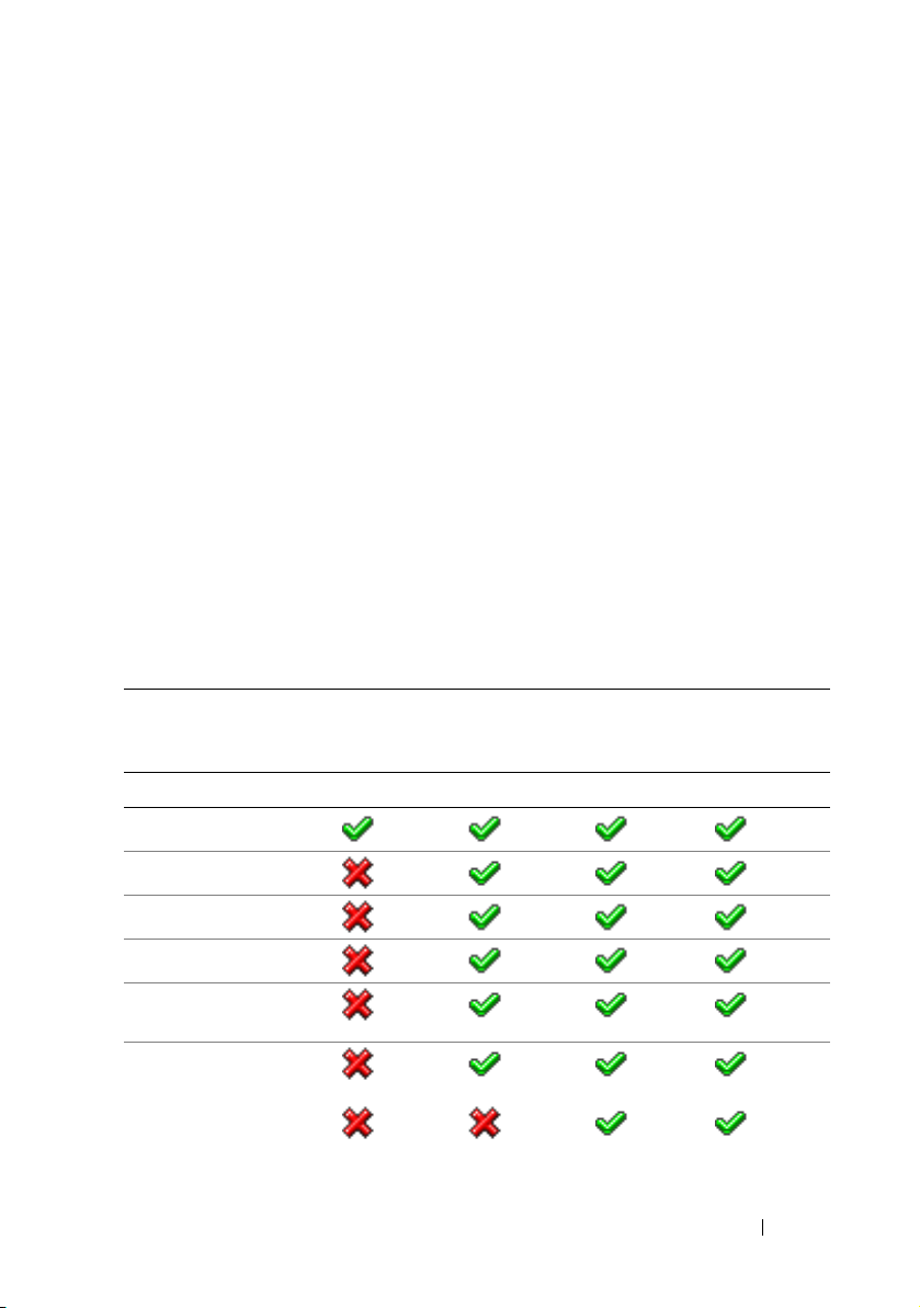
Table 1-1 lists the features available for BMC, iDRAC6 Express, iDRAC6
Enterprise, and vFlash Media.
Table 1-1. iDRAC6 Feature List
Feature BMC iDRAC6
Express
Interface and Standards Support
IPMI 2.0
Web-based GUI
SNMP
WSMAN
SMASH-CLP (SSHonly)
RACADM Command
Line (SSH and local)
RACADM Command
Line (remote)
iDRAC6
Enterprise
iDRAC6 Overview 21
iDRAC6
Enterprise
with vFlash
Page 22
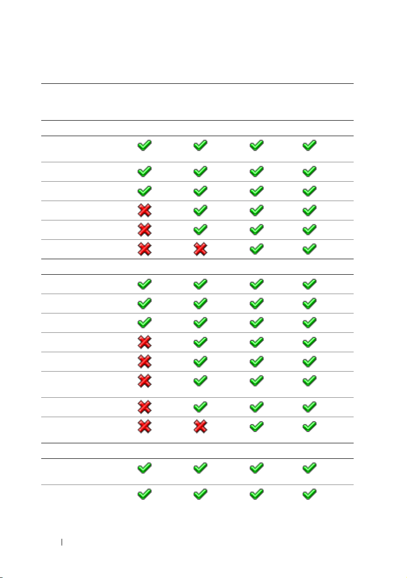
Table 1-1. iDRAC6 Feature List
(continued)
Feature BMC iDRAC6
Express
Connectivity
Shared/Failover Network
Modes
IPv4
VLAN Tagging
IPv6
Dynamic DNS
Dedicated NIC
Security and Authentication
Role-based Authority
Local Users
SSL Encryption
Active Directory
Generic LDAP Support
iDRAC6
Enterprise
iDRAC6
Enterprise
with vFlash
Tw o - f a c t o r
Authentication
1
Single sign-on
PK Authentication (for
SSH)
Remote Management and Remediation
Remote Firmware
2
Update
Server Power Control
2
22 iDRAC6 Overview
Page 23
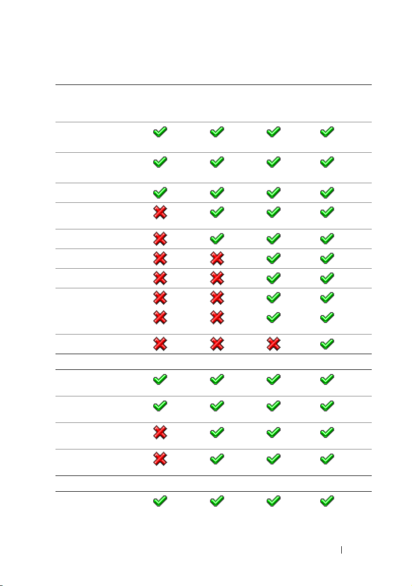
Table 1-1. iDRAC6 Feature List
(continued)
Feature BMC iDRAC6
Express
Serial-over-LAN
(with proxy)
Serial-over-LAN
(no proxy)
Power Capping
Last Crash Screen
Capture
Boot Capture
Virtual Media
Virtual Console
Virtual Console Sharing
3
3
3
Remote Virtual Console
Launch
vFlash
Monitoring
Sensor Monitoring and
2
Alerting
Real-time Power
Monitoring
Real-time Power
Graphing
Historical Power
Counters
Logging
System Event Log (SEL)
iDRAC6
Enterprise
iDRAC6
Enterprise
with vFlash
iDRAC6 Overview 23
Page 24
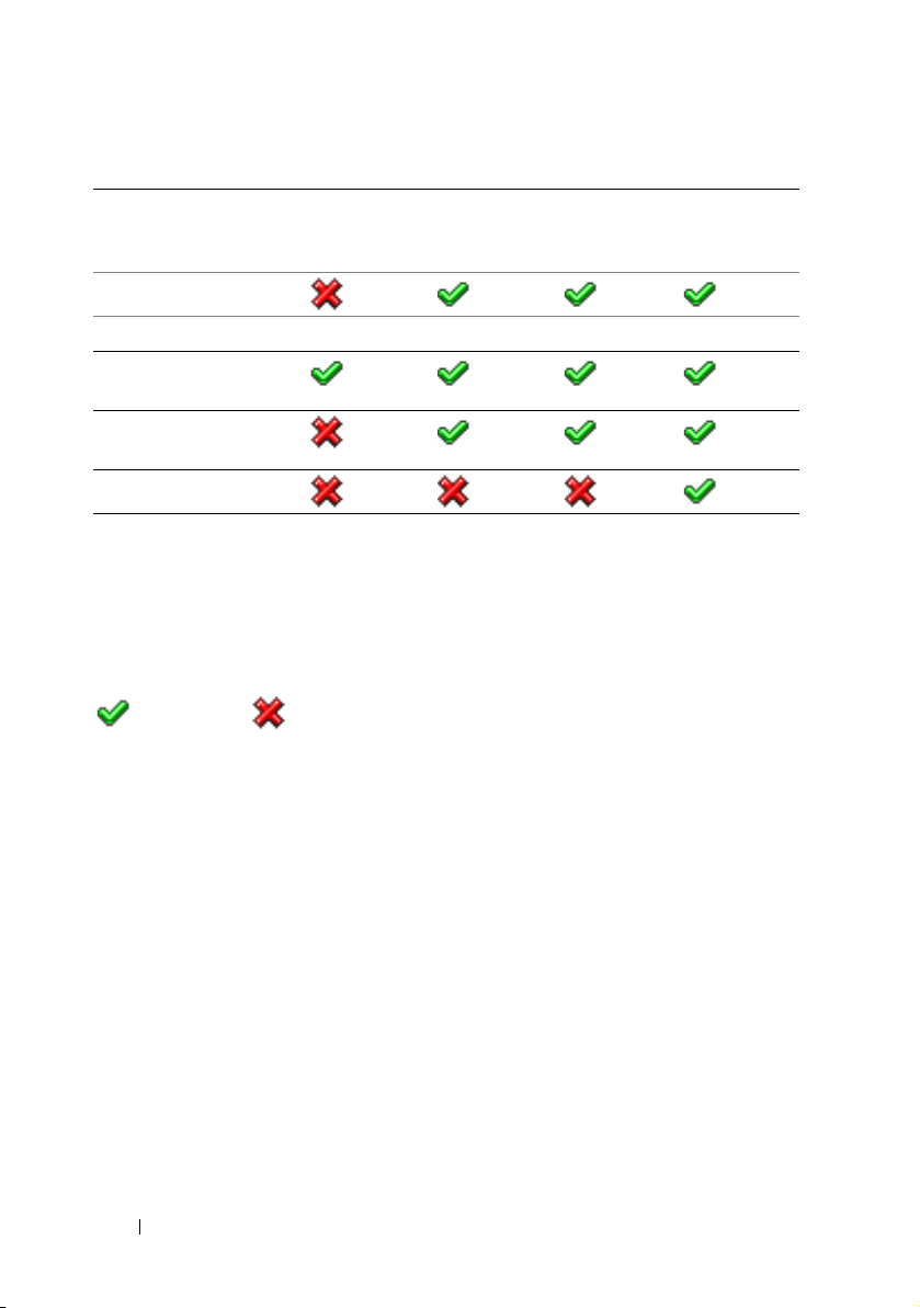
Table 1-1. iDRAC6 Feature List
(continued)
Feature BMC iDRAC6
Express
RAC Log
Lifecycle Controller
Unified Server
Configurator
Remote Services
(through WS-MAN)
Par t Replacem ent
1
Two-factor authentication requires Internet Explorer.
2
Feature is available only through IPMI and not through a Web GUI.
3
Virtual Console and Virtual Media are available using both Java and Active-X plug-
ins.
4
The Unified Server Configurator available through BMC is limited to operating
system installation and diagnostics only.
= Supported; =Not Supported
4
iDRAC6
Enterprise
iDRAC6
Enterprise
with vFlash
The iDRAC6 provides the following security features:
• Single Sign-on, Two-Factor Authentication, and Public Key
Authentication
• User authentication through Active Directory (optional), LDAP
authentication (optional) or hardware-stored user IDs and passwords
• Role-based authorization, which enables an administrator to configure
specific privileges for each user
• User ID and password configuration through the Web-based interface
or SM-CLP
• SM-CLP and Web interfaces, which support 128-bit and 40-bit encryption
(for countries where 128 bit is not acceptable), using the SSL 3.0 standard
• Session time-out configuration (in seconds) through the Web interface or
SM-CLP
24 iDRAC6 Overview
Page 25

• Configurable IP ports (where applicable)
NOTE: Telnet does not support SSL encryption.
• SSH, which uses an encrypted transport layer for higher security
• Login failure limits per IP address, with login blocking from the IP address
when the limit is exceeded
• Ability to limit the IP address range for clients connecting to the iDRAC6
Supported Platforms
For the latest supported platforms, see the iDRAC6 Readme file and the
Dell Systems Software Support Matrix available at support.dell.com/manuals.
Supported Operating Systems
For the latest information, see the iDRAC6 Readme file and the Dell Systems
Software Support Matrix available at support.dell.com/manuals.
Supported Web Browsers
For the latest information, see the iDRAC6 Readme file and the Dell Systems
Software Support Matrix available at support.dell.com/manuals.
NOTE: Due to serious security flaws, support for SSL 2.0 has been discontinued.
Your browser must be configured to enable SSL 3.0 in order to work properly.
Internet Explorer 6.0 is not supported.
iDRAC6 Overview 25
Page 26

Supported Remote Access Connections
Table 1-2 lists the connection features.
Table 1-2. Supported Remote Access Connections
Connection Features
iDRAC6 NIC
• 10Mbps/100Mbs/Ethernet
• DHCP support
• SNMP traps and e-mail event notification
• Support for SM-CLP (Telnet, SSH, and RACADM) command
shell, for operations such as iDRAC6 configuration, system
boot, reset, power-on, and shutdown commands
• Support for IPMI utilities, such as IPMItool and ipmish
iDRAC6 Ports
Table 1-3 lists the ports iDRAC6 listens on for connections. Table 1-4
identifies the ports that the iDRAC6 uses as a client. This information is
required when opening firewalls for remote access to an iDRAC6.
Table 1-3. iDRAC6 Server Listening Ports
Port Number Function
22*
23*
80*
443*
623
5900*
* Configurable port
SSH
Te ln e t
HTTP
HTTPS
RMCP/RMCP+
Virtual Console keyboard/mouse, Virtual
Media Service, Virtual Media Secure Service,
and Virtual Console video
26 iDRAC6 Overview
Page 27

Table 1-4. iDRAC6 Client Ports
Port Number Function
25
53
68
69
162
636
3269
SMTP
DNS
DHCP-assigned IP address
TFTP
SNMP trap
LDAPS
LDAPS for global catalog (GC)
Other Documents You May Need
In addition to this guide, the following documents available on the Dell
Support website at support.dell.com/manuals provide additional information
about the setup and operation of the iDRAC6 in your system. On the
Manuals page, click SoftwareSystems Management. Click on the
appropriate product link on the right-side to access the documents.
• The iDRAC6 online help provides detailed information about using the
Web-based interface.
•The
•The Dell Lifecycle Controller User Guide provides information on the
•The
•The
iDRAC6 Administrator Reference Guide
provides information about
the RACADM subcommands, supported interfaces, and iDRAC6 property
database groups and object definitions.
Unified Server Configurator (USC), the Unified Server Configurator –
Lifecycle Controller Enabled (USC – LCE), and Remote Services.
Dell Systems Software Support Matrix
provides information about the
various Dell systems, the operating systems supported by these systems,
and the Dell OpenManage components that can be installed on these
systems.
Dell OpenManage Server Administrator Installation Guide
contains
instructions to help you install Dell OpenManage Server Administrator.
iDRAC6 Overview 27
Page 28

•The
• See the
• For installing an iDRAC6, see your
• See the
• See the
• See the
•The Glossary provides information about the terms used in this
The following system documents are also available to provide more
information about the system in which your iDRAC6 is installed:
• The safety instructions that came with your system provide important
•The
•The
•The
• Systems management software documentation describes the features,
• Operating system documentation describes how to install (if necessary),
Dell OpenManage Management Station Software Installation Guide
contains instructions to help you install Dell OpenManage management
station software that includes Baseboard Management Utility, DRAC
Tools, and Active Directory Snap-In.
Dell OpenManage IT Assistant User’s Guide
using IT Assistant.
Hardware Owner’s Manual
Dell OpenManage Server Administrator User’s Guide
information about installing and using Server Administrator.
Dell Update Packages User’s Guide
obtaining and using Dell Update Packages as part of your system update
strategy.
Dell OpenManage Baseboard Management Controller Utilities
User’s Guide
document.
safety and regulatory information. For additional regulatory information,
see the Regulatory Compliance home page at
www.dell.com/regulatory_compliance
included within this document or as a separate document.
Rack Installation Instructions
describe how to install your system into a rack.
Getting Started Guide
up your system, and technical specifications.
Hardware Owner’s Manual
features and describes how to troubleshoot the system and install or
replace system components.
requirements, installation, and basic operation of the software.
configure, and use the operating system software.
for information about the iDRAC6 and the IPMI interface.
included with your rack solution
provides an overview of system features, setting
provides information about system
for information about
. Warranty information may be
for information about
.
for
28 iDRAC6 Overview
Page 29

• Documentation for any components you purchased separately provides
information to configure and install these options.
• Updates are sometimes included with the system to describe changes to
the system, software, and/or documentation.
NOTE: Always read the updates first because they often supersede
information in other documents.
• Release notes or readme files may be included to provide last-minute
updates to the system or documentation or advanced technical reference
material intended for experienced users or technicians.
iDRAC6 Overview 29
Page 30

30 iDRAC6 Overview
Page 31

2
Getting Started With the iDRAC6
The iDRAC6 enables you to remotely monitor, troubleshoot, and repair a
Dell system even when the system is down. The iDRAC6 offers features like
Virtual Console, Virtual Media, Smart Card authentication, and Single SignOn (SSO).
The management station is the system from which an administrator remotely
manages a Dell system that has an iDRAC6. The systems that are monitored
in this way are called managed systems.
Optionally, you can install Dell OpenManage software on the management
station as well as the managed system. Without the managed system software,
you cannot use the RACADM locally, and the iDRAC6 cannot capture the last
crash screen.
To set up iDRAC6, follow these general steps:
NOTE: This procedure may differ for various systems. See your specific system’s
Hardware Owner’s Manual
support.dell.com/manuals for precise instructions on how to perform this
procedure.
1
Configure the iDRAC6 properties, network settings, and users —
configure the iDRAC6 by using either the iDRAC6 Configuration
Utility, the Web-based interface, or the RACADM.
2
For a Windows system, configure the Microsoft Active Directory to
provide access to the iDRAC6, allowing you to add and control iDRAC6
user privileges to your existing users in your Active Directory software.
3
Configure Smart Card authentication — Smart Card provides an added
level of security to your enterprise.
4
Configure remote access points, such as Virtual Console and
virtual media.
5
Configure the security settings.
6
Configure alerts for efficient systems management capability.
7
Configure the iDRAC6 Intelligent Platform Management Interface
(IPMI) settings to use the standards-based IPMI tools to manage the
systems on your network.
on the Dell Support Website at
Yo u c a n
Getting Started With the iDRAC6 31
Page 32

32 Getting Started With the iDRAC6
Page 33

3
Basic Installation of the iDRAC6
This section provides information about how to install and set up your
iDRAC6 hardware and software.
Before You Begin
Ensure that you have the following items that were included with your
system, prior to installing and configuring the iDRAC6 software:
• iDRAC6 hardware (currently installed or in the optional kit)
• iDRAC6 installation procedures (located in this chapter)
•
Dell Systems Management Tools and Documentation
Installing the iDRAC6 Express/Enterprise Hardware
NOTE: The iDRAC6 connection emulates a USB keyboard connection. As a result,
when you restart the system, the system will not notify you if your keyboard is
not attached.
The iDRAC6 Express/Enterprise may be preinstalled on your system, or
available separately. To get started with the iDRAC6 that is installed on your
system, see "Software Installation and Configuration Overview" on page 36.
If an iDRAC6 Express/Enterprise is not installed on your system, see your
platform Hardware Owner’s Manual for hardware installation instructions.
DVD
Basic Installation of the iDRAC6 33
Page 34

Configuring Your System to Use an iDRAC6
To configure your system to use an iDRAC6, use the iDRAC6
Configuration Utility.
To run the iDRAC6 Configuration Utility:
1
Turn on or restart your system.
2
Press <Ctrl><E> when prompted during POST.
If your operating system begins to load before you press <Ctrl><E>,
allow the system to finish booting, and then restart your system and try again.
3
Configure the LOM.
a
Use the arrow keys to select
NIC Selection
b
Use the arrow keys to select one of the following NIC modes:
•
Dedicated
device to utilize the dedicated network interface available on the
iDRAC6 Enterprise. This interface is not shared with the host
operating system and routes the management traffic to a separate
physical network, enabling it to be separated from the application
traffic. This option is available only if an iDRAC6 Enterprise is
installed in the system. After you install the iDRAC6 Enterprise
card, ensure that you change the
This can be done either through the iDRAC6 Configuration
Utility, the iDRAC6 Web Interface, or through RACADM.
•
Shared
host operating system. The remote access device network interface
is fully functional when the host operating system is configured for
NIC teaming. The remote access device receives data through
NIC 1 and NIC 2, but transmits data only through NIC 1. If NIC 1
fails, the remote access device will not be accessible.
is displayed.
— Select this option to enable the remote access
— Select this option to share the network interface with the
LAN Parameters
NIC Selection
and press <Enter>.
to
Dedicated
.
34 Basic Installation of the iDRAC6
Page 35

•
Shared with Failover LOM2
— Select this option to share the
network interface with the host operating system. The remote
access device network interface is fully functional when the host
operating system is configured for NIC teaming. The remote
access device receives data through NIC 1 and NIC 2, but
transmits data only through NIC 1. If NIC 1 fails, the remote
access device fails over to NIC 2 for all data transmission.
The remote access device continues to use NIC 2 for data
transmission. If NIC 2 fails, the remote access device fails over
all data transmission back to NIC 1 if the failure in NIC1 has
been corrected.
•
Shared with Failover All LOMs
— Select this option to share the
network interface with the host operating system. The remote
access device network interface is fully functional when the host
operating system is configured for NIC teaming. The remote
access device receives data through NIC 1, NIC 2, NIC 3, and
NIC 4; but it transmits data only through NIC 1. If NIC 1 fails,
the remote access device fails over all data transmission to NIC 2.
If NIC 2 fails, the remote access device fails over all data
transmission to NIC 3. If NIC 3 fails, the remote access device
fails over all data transmission to NIC 4. If NIC 4 fails the remote
access device fails over all data transmission back to NIC 1, but
only if the original NIC 1 failure has been corrected. This option
may not be available on iDRAC6 Enterprise.
4
Configure the network controller LAN parameters to use DHCP or a
Static IP address source.
a
Using the down-arrow key, select
b
Using the up-arrow and down-arrow keys, select
c
Using the right-arrow and left-arrow keys, select
or
d
If you selected
Mask
e
Press <Esc>.
5
Press <Esc>.
6
Select
Static
.
Static
, configure the
, and
Default Gateway
Save Changes and Exit
LAN Parameters
settings.
.
, and press <Enter>.
IP Address Source
DHCP, Auto Config
Ethernet IP Address, Subnet
.
Basic Installation of the iDRAC6 35
Page 36

Software Installation and Configuration Overview
This section provides a high-level overview of the iDRAC6 software
installation and configuration process. For more information on the iDRAC6
software components, see "Installing the Software on the Managed System"
on page 37.
Installing iDRAC6 Software
To install iDRAC6 software:
1
Install the iDRAC6 software on the managed system. See
Software on the Managed System
2
Install the iDRAC6 software on the management station. See "Installing
the Software on the Management Station" on page 37.
" on page 37.
Configuring iDRAC6
To configure iDRAC6:
1
Use one of the following configuration tools:
• Web-based interface (see "Configuring the iDRAC6 Using the Web
Interface" on page 45)
• RACADM CLI (see
at
support.dell.com/manuals
• Telnet console (see "Using a Telnet Console" on page 89)
iDRAC6 Administrator Reference Guide
)
"Installing the
available
NOTE: Using more than one iDRAC6 configuration tool at the same time may
generate unexpected results.
2
Configure the iDRAC6 network settings. See "Configuring the iDRAC6
Network Settings" on page 109.
3
Add and configure iDRAC6 users. See "Adding and Configuring
iDRAC6 Users" on page 129.
4
Configure the Web browser to access the Web-based interface. See
"Configuring a Supported Web Browser" on page 41.
5
Disable the Microsoft Windows Automatic Reboot Option. See "Disabling
the Windows Automatic Reboot Option" on page 316.
6
Update the iDRAC6 Firmware. See "Updating the iDRAC6 Firmware" on
page 39.
36 Basic Installation of the iDRAC6
Page 37

Installing the Software on the Managed System
Installing software on the managed system is optional. Without the managed
system software, you cannot use the RACADM locally, and the iDRAC6
cannot capture the last crash screen.
To install the managed system software, install the software on the managed
system using the
For instructions about how to install this software, see your Software Quick
Installation Guide available
support.dell.com\manuals.
Managed system software installs your choices from the appropriate version
of Dell OpenManage Server Administrator on the managed system.
NOTE: Do not install the iDRAC6 management station software and the iDRAC6
managed system software on the same system.
If Server Administrator is not installed on the managed system, you cannot
view the system’s last crash screen or use the Auto Recovery feature.
For more information about the last crash screen, see "Viewing the Last
System Crash Screen" on page 333.
Dell Systems Management Tools and Documentation
on the Dell Support website
at
DVD.
Installing the Software on the Management Station
Your system includes the Dell Systems Management Tools and Documentation
DVD. This DVD includes the following components:
• DVD root - Contains the Dell Systems Build and Update Utility,
which provides server setup and system installation information
• SYSMGMT - Contains the systems management software products
including Dell OpenManage Server Administrator
For information about Server Administrator, IT Assistant, and Unified Server
Configurator, see the Server Administrator User's Guide, the IT Assistant
User’s Guide, and the Lifecycle Controller User’s Guide available on the Dell
Support website at support.dell.com/manuals.
Installing and Removing RACADM on a Linux Management Station
To use the remote RACADM functions, install RACADM on a management
station running Linux.
Basic Installation of the iDRAC6 37
Page 38

NOTE: When you run Setup on the
Documentation
installed on your management station.
DVD, the RACADM utility for all supported operating systems is
Dell Systems Management Tools and
Installing RACADM
1
Log on as root to the system where you want to install the management
station components.
2
If necessary, mount the
Documentation
DVD using the following command or a similar command:
Dell Systems Management Tools and
mount /media/cdrom
3
Navigate to the
/linux/rac
directory and execute the following command:
rpm -ivh *.rpm
For help with the RACADM command, type racadm help after issuing the
previous commands.
Uninstalling RACADM
To uninstall RACADM, open a command prompt and type:
rpm -e <racadm_package_name>
where <racadm_package_name> is the rpm package that was used to
install the RAC software.
For example, if the rpm package name is srvadmin-racadm5, then type:
rpm -e srvadmin-racadm5
38 Basic Installation of the iDRAC6
Page 39

Updating the iDRAC6 Firmware
Use one of the following methods to update your iDRAC6 firmware.
• Web-based Interface (see "Updating the iDRAC6 Firmware Using the
Web-Based Interface" on page 40)
• RACADM CLI (see "Updating the iDRAC6 Firmware Using RACADM"
on page 40)
• Dell Update Packages (see "Updating the iDRAC6 Firmware Using Dell
Update Packages for Supported Windows and Linux Operating Systems"
on page 40)
Before You Begin
Before you update your iDRAC6 firmware using local RACADM or the
Dell Update Packages, perform the following procedures. Otherwise, the
firmware update operation may fail.
1
Install and enable the appropriate IPMI and managed node drivers.
2
If your system is running a Windows operating system, enable and start
the
Windows Management Instrumentation
3
If you are using iDRAC6 Enterprise and your system is running SUSE Linux
Enterprise Server (version 10) for Intel EM64T, start the
4
Disconnect and unmount Virtual Media.
NOTE: If iDRAC6 firmware update is interrupted for any reason, a wait of up to
30 minutes may be required before a firmware update will be allowed again.
5
Ensure that the USB is enabled.
(WMI) service.
Raw
service.
Downloading the iDRAC6 Firmware
To update your iDRAC6 firmware, download the latest firmware from the
Dell Support website located at support.dell.com and save the file to your
local system.
The following software components are included with your iDRAC6 firmware
package:
• Compiled iDRAC6 firmware code and data
• Web-based interface, JPEG, and other user interface data files
• Default configuration files
Basic Installation of the iDRAC6 39
Page 40

Updating the iDRAC6 Firmware Using the Web-Based Interface
For detailed information, see "Updating the iDRAC6 Firmware/System
Services Recovery Image" on page 77.
Updating the iDRAC6 Firmware Using RACADM
You can update the iDRAC6 firmware using the CLI-based RACADM tool.
If you have installed Server Administrator on the managed system, use local
RACADM to update the firmware.
1
Download the iDRAC6 firmware image from the Dell Support website at
support.dell.com
For example:
C:\downloads\firmimg.d6
2
Run the following RACADM command:
racadm fwupdate -pud c:\downloads\
You can also update the firmware using remote RACADM and
aTFTPserver.
For example:
racadm -r <iDRAC6 IP address> -u <username> -p
<password> fwupdate -g -u -a <path>
where
path
including the TFTP server IP address.
to the managed system.
is the location on the TFTP server where the
firmimg.d6
is stored
Updating the iDRAC6 Firmware Using Dell Update Packages for Supported Windows and Linux Operating Systems
Download and run the Dell Update Packages for supported Windows and
Linux operating systems from
For more information, see the Dell Update Package User’s Guide available on
the
Dell Support website at
NOTE: When updating the iDRAC6 firmware using the Dell Update Package utility
in Linux, you may see these messages displayed on the console:
usb 5-2: device descriptor read/64, error -71
40 Basic Installation of the iDRAC6
Dell Support website at
support.dell.com\manuals
support.dell.com
.
.
Page 41

usb 5-2: device descriptor not accepting
address 2, error -71
These errors are cosmetic in nature and should be ignored. These messages
are caused due to reset of the USB devices during the firmware update
process and are harmless.
Configuring a Supported Web Browser
The following sections provide instructions for configuring the supported
Web browsers.
Configuring Your Web Browser to Connect to the iDRAC6 Web-Based Interface
If you are connecting to the iDRAC6 Web-based interface from a
management station that connects to the Internet through a proxy server,
you must configure the Web browser to access the Internet from this server.
To configure your Internet Explorer Web browser to access a proxy server:
1
Open a Web browser window.
2
Click
Tools
3
From the
4
Under
Local Area Network (LAN) settings
5
If the
Use a proxy server
local addresses
6
Click OK twice.
, and click
Internet Options
Internet Options
box.
.
window, click the
box is selected, select the
Connections
, click
tab.
LAN Settings
Bypass proxy server for
.
List of Trusted Domains
When you access the iDRAC6 Web-based interface through the Web
browser, you are prompted to add the iDRAC6 IP address to the list of trusted
domains if the IP address is missing from the list. When completed, click
Refresh or relaunch the Web browser to reestablish a connection to the
iDRAC6 Web-based interface.
Basic Installation of the iDRAC6 41
Page 42

Viewing Localized Versions of the Web-Based Interface
Windows
The iDRAC6 Web-based interface is supported on the following Windows
operating system languages:
•English
•French
•German
•Spanish
•Japanese
• Simplified Chinese
To view a localized version of the iDRAC6 Web-based interface in Internet
Explorer:
1
Click the
2
In the
3
In the
4
In the
To select more than one language, press <Ctrl>.
5
Select your preferred language and click
the top of the list.
6
Click OK.
7
In the
Tools
menu and select
Internet Options
Language Preference
Add Language
Language Preference
window, click
window, select a supported language.
Internet Options
Languages
window, click
window, click OK.
Add
Move Up
.
.
.
to move the language to
Linux
If you are running Virtual Console on a Red Hat Enterprise Linux (version 4)
client with a Simplified Chinese Graphical User Interface (GUI), the viewer
menu and title may appear in random characters. This issue is caused by an
incorrect encoding in the Red Hat Enterprise Linux (version 4) Simplified
Chinese operating system. To fix this issue, access and modify the current
encoding settings by performing the following steps:
1
Open a command terminal.
2
Type “locale” and press <Enter>. The following output is displayed.
42 Basic Installation of the iDRAC6
Page 43

LANG=zh_CN.UTF-8
LC_CTYPE="zh_CN.UTF-8"
LC_NUMERIC="zh_CN.UTF-8"
LC_TIME="zh_CN.UTF-8"
LC_COLLATE="zh_CN.UTF-8"
LC_MONETARY="zh_CN.UTF-8"
LC_MESSAGES="zh_CN.UTF-8"
LC_PAPER="zh_CN.UTF-8"
LC_NAME="zh_CN.UTF-8"
LC_ADDRESS="zh_CN.UTF-8"
LC_TELEPHONE="zh_CN.UTF-8"
LC_MEASUREMENT="zh_CN.UTF-8"
LC_IDENTIFICATION="zh_CN.UTF-8"
LC_ALL=
3
If the values include “zh_CN.UTF-8”, no changes are required. If the
values do not include “zh_CN.UTF-8”, go to step 4.
4
Navigate to the
5
In the file, apply the following changes:
/etc/sysconfig/i18n
file.
Current entry:
LANG="zh_CN.GB18030"
SUPPORTED="zh_CN.GB18030:zh_CH.GB2312:zh_CN:zh"
Updated entry:
LANG="zh_CN.UTF-8"
SUPPORTED="zh_CN.UTF8:zh_CN.GB18030:zh_CH.GB2312:zh_CN:zh"
6
Log out and then log in to the operating system.
7
Relaunch the iDRAC6.
When you switch from any other language to the Simplified Chinese
language, ensure that this fix is still valid. If not, repeat this procedure.
For advanced configurations of the iDRAC6, see "Advanced iDRAC6
Configuration" on page 87.
Basic Installation of the iDRAC6 43
Page 44

44 Basic Installation of the iDRAC6
Page 45

4
Configuring the iDRAC6 Using the Web Interface
The iDRAC6 provides a Web interface that enables you to configure the
iDRAC6 properties and users, perform remote management tasks, and
troubleshoot a remote (managed) system for problems. For everyday systems
management, use the iDRAC6 Web interface. This chapter provides
information about how to perform common systems management tasks with
the iDRAC6 Web interface and provides links to related information.
Most Web interface configuration tasks can also be performed with
RACADM commands or with Server Management-Command Line Protocol
(SM-CLP) commands.
Local RACADM commands are executed from the managed server.
SM-CLP and SSH/Telnet RACADM commands are executed in a shell that
can be accessed remotely with a Telnet or SSH connection. For more
information about SM-CLP, see "Using the iDRAC6 SM-CLP Command
Line Interface" on page 231. For more information about RACADM
commands see the iDRAC6 Administrator Reference Guide available on the
Dell Support website at support.dell.com/manuals.
CAUTION: When you refresh the browser by clicking "Refresh" or pressing F5,
you may get logged out of the Web Graphical User Interface (GUI) session or be
redirected to the "System Summary" page.
Configuring the iDRAC6 Using the Web Interface 45
Page 46

Accessing the Web Interface
To access the iDRAC6 Web interface, perform the following steps:
1
Open a supported Web browser window.
To access the Web interface using an IPv4 address, go to step 2.
To access the Web interface using an IPv6 address, go to step 3.
2
Access the Web interface using an IPv4 address; you must have
IPv4 enabled:
In the browser
https://<iDRAC-IPv4-address>
Then, press <Enter>.
3
Access the Web interface using an IPv6 address; you must have IPv6
enabled.
In the browser
https://[<iDRAC-IPv6-address>]
Then, press <Enter>.
4
If the default HTTPS port number, port 443, has been changed, type:
https://<iDRAC-IP-address>:<port-number>
where iDRAC-IP-address is the IP address for the
iDRAC6 and port-number is the HTTPS port number.
Address
Address
bar, type:
bar, type:
5
In the
Address
<Enter>.
If the default HTTPS port number (port 443) has been changed, type:
https://<iDRAC-IP-address>:<port-number>
where
iDRAC-IP-address
port-number
The iDRAC6 Login window is displayed.
46 Configuring the iDRAC6 Using the Web Interface
field, type
is the HTTPS port number.
https://<
is the IP address for the iDRAC6 and
iDRAC-IP-address> and press
Page 47

Logging In
You can log in as either an iDRAC6 user or as a Microsoft Active Directory
user. The default user name and password for an iDRAC6 user are root and
calvin, respectively.
You must have been granted Login to iDRAC privilege by the administrator
to log in to iDRAC6.
To log in, perform the following steps:
1
In the
Username
• Your iDRAC6 user name.
The user name for local users is case
it_user
• Your Active Directory user name.
Active Directory names can be entered in any of the forms
<
username
<
user
dell.com\john_doe,or
2
In the
Password
user password. Passwords are case
3
From the
iDRAC6 user, or select any of the available domains for logging in as a
Active Directory user.
field, type one of the following:
-
sensitive. Examples are
, or john_doe.
>, <
domain
>\<
>@<
username
domain
>. They are not case-sensitive. Examples are
JOHN_DOE@DELL.COM
>, <
domain
>/<
username
.
field, type your iDRAC6 user password or Active Directory
-
sensitive.
Domain
drop-down box, select
This iDRAC
for logging in as an
root
>, or
,
NOTE: For Active Directory users, if you have specified the domain name as a
part of the Username, select
4
Click OK or press <Enter>.
Configuring the iDRAC6 Using the Web Interface 47
This iDRAC
from the drop-down menu.
Page 48

Logging Out
1
In the upper-right corner of the main window, click
Logout
to close
the session.
2
Close the browser window.
NOTE: The Logout button does not appear until you log in.
NOTE: Closing the browser without gracefully logging out may cause the session
to remain open until it times out. It is strongly recommended that you click the
logout button to end the session; otherwise, the session may remain active until the
session timeout is reached.
NOTE: Closing the iDRAC6 Web interface within Microsoft Internet Explorer using
the close button ("x") at the top right corner of the window may generate an
application error. To fix this issue, download the latest Cumulative Security Update
for Internet Explorer from the Microsoft Support website, located at
support.microsoft.com.
CAUTION: If you have opened multiple Web GUI sessions either through <Ctrl+T>
or <Ctrl+N> to access the same iDRAC6 from the same management station, and
then log out of any one session, all the Web GUI sessions will be terminated.
Using Multiple Browser Tabs and Windows
Different versions of Web browsers exhibit different behaviors when opening
new tabs and windows. Internet Explorer (IE) version 7 and IE 8 have the
option to open tabs and windows. Each tab inherits the characteristics of the
most recently opened tab. Press <Ctrl–T> to open a new tab and
<Ctrl–N> to open a new browser window from the active session. You will
be logged in with your already authenticated credentials. Closing any one tab
expires all iDRAC6 Web interface tabs. Also, if a user logs in with Power User
privileges on one tab, and then logs in as Administrator on another tab, both
open tabs have Administrator privileges.
Tab behavior for Mozilla Firefox 2 and Firefox 3 is the same as IE 7 and IE 8;
new tabs are new sessions. Screens launched with Firefox browser will operate
with the same privileges as the latest window opened. For example, if one
Firefox window is open with a Power User logged in and another window is
opened with Administrator privileges, both users will have Administrator
privileges.
48 Configuring the iDRAC6 Using the Web Interface
Page 49

Table 4-1. User Privilege Behavior in Supported Browsers
Browser Tab Behavior Window Behavior
Microsoft Internet
Explorer 6
Microsoft IE7 and IE8 From latest session opened New session
Firefox 2 and Firefox 3 From latest session opened From latest session opened
Not applicable New session
Configuring the iDRAC6 NIC
This section assumes that the iDRAC6 has already been configured and is
accessible on the network. See "Configuring iDRAC6" on page 36 for help
with the initial iDRAC6 network configuration.
Configuring the Network and IPMI LAN Settings
NOTE: You must have Configure iDRAC permission to perform the following steps.
NOTE: Most DHCP servers require a server to store a client identifier token in its
reservations table. The client (iDRAC, for example) must provide this token during
DHCP negotiation. The iDRAC6 supplies the client identifier option using a one-byte
interface number (0) followed by a six-byte MAC address.
NOTE: If you are running with Spanning Tree Protocol (STP) enabled, ensure that
you also have PortFast or a similar technology turned on as follows:
- On the ports for the switch connected to iDRAC6
- On the ports connected to the management station running an iDRAC Virtual
Console session
NOTE: You may see the following message if the system halts during POST: Strike
the F1 key to continue, F2 to run the system setup program
One possible reason for the error is a network storm event, which causes you to lose
communication with the iDRAC6. After the network storm subsides, restart the system.
1
Click
Remote Access
2
On the
Network
settings, IPv4 settings, IPv6 settings, IPMI settings, and VLAN settings.
Se e Ta b le 4- 2 , Tab le 4- 3 , Tab le 4- 4 , Tab le 4 - 5,
Table 4-6, and Table 4-7 for descriptions of these settings.
3
When you have completed entering the required settings, click
Network/Security Network.
page, you can enter Network settings, Common iDRAC6
Apply
.
Configuring the iDRAC6 Using the Web Interface 49
Page 50

4
Click the appropriate button to continue. See Table 4-8.
Table 4-2. Network Settings
Setting Description
NIC Selection Configures the current mode out of the four possible modes:
• Dedicated
• Shared (LOM1)
• Shared with Failover LOM2
• Shared with Failover All LOMs
NOTE: The Dedicated option is only available for iDRAC Enterprise
cards and the Shared with Failover All LOMs option may be available
only for few systems.
iDRAC6 will not communicate locally through the same physical
port if NIC selection is set to either Shared or Shared with Failover
modes. This is because a network switch will not send out packets
through the same port it received the packets.
If the NIC selection is set to Shared with Failover (LOM 2 or all
LOMs), it is recommended not to connect the LOMs to diffferent
network broadcast domains.
It is recommended not to team LOMs with add-in network
controllers when iDRAC is configured for any shared mode. Any type
of team between the LOMs is acceptable irrespective of the NIC
selection mode (shared/shared with failover LOM2/shared with
failover all LOMs.)
MAC Address Displays the Media Access Control (MAC) address that uniquely
identifies each node in a network.
Enable NIC When checked, indicates that the NIC is enabled and activates the
remaining controls in this group. When a NIC is disabled, all
communication to and from the iDRAC6 via the network is blocked.
The default is On.
50 Configuring the iDRAC6 Using the Web Interface
Page 51

Table 4-2. Network Settings
Setting Description
Auto
Negotiation
If set to On, displays the Network Speed and Mode by
communicating with the nearest router or hub. If set to Off, allows
you to set the Network Speed and Duplex Mode manually.
If NIC Selection is not set to Dedicated, Auto Negotiation setting
will always be enabled (On).
(continued)
NOTE: When the server is off, the embedded LOM ports support a
maximum speed of 100Mbps. Therefore, configuring the LOMs and
switch to support auto-negotiation ensures connectivity to iDRAC
through system power transitions.
Network Speed Enables you to set the Network Speed to 100 Mb or 10 Mb to match
your network environment. This option is not available if Auto
Negotiation is set to On.
Duplex Mode Enables you to set the Duplex Mode to full or half to match your
network environment. This option is not available if Auto
Negotiation is set to On.
NIC MTU Enables you to set the Maximum Transmission Unit (MTU) size on
the NIC.
Table 4-3. Common Settings
Setting Description
Register iDRAC
on DNS
DNS iDRAC Name Displays the iDRAC6 name only when Register iDRAC on
Auto Config
Domain Name
Registers the iDRAC6 name on the DNS server.
The default is Disabled.
DNS is selected. The default name is idrac-service_tag,
where service_tag is the service tag number of the Dell server,
for example: idrac-00002.
Uses the default DNS domain name. When the checkbox is not
selected and the Register iDRAC on DNS option is selected,
modify the DNS domain name in the DNS Domain Name field.
The default is Disabled.
Configuring the iDRAC6 Using the Web Interface 51
Page 52

Table 4-3. Common Settings
Setting Description
DNS Domain
Name
Table 4-4. IPv4 Settings
Setting Description
Enable IPv4 If NIC is enabled, this selects IPv4 protocol support and sets
DHCP Enable Prompts the iDRAC6 to obtain an IP address for the NIC from
IP Address Specifies the iDRAC6 NIC IP address.
Subnet Mask Allows you to enter or edit a static IP address for the iDRAC6
Gateway The address of a router or switch. The value is in the "dot
Use DHCP to
obtain DNS server
addresses
(continued)
The default DNS Domain Name is blank. When the Auto
Config Domain Name checkbox is selected, this option is
disabled.
the other fields in this section to be enabled.
the Dynamic Host Configuration Protocol (DHCP) server.
The default is off.
NIC. To change this setting, deselect the Use DHCP
(For NIC IP Address) checkbox.
separated" format, such as 192.168.0.1.
Enable DHCP to obtain DNS server addresses by selecting the
Use DHCP to obtain DNS server addresses checkbox. When
not using DHCP to obtain the DNS server addresses, provide
the IP addresses in the Preferred DNS Server and Alternate
DNS Server fields.
The default is off.
NOTE: When the Use DHCP to obtain DNS server addresses
checkbox is selected, IP addresses cannot be entered into the
Preferred DNS Server and Alternate DNS Server fields.
Preferred DNS
Server
Alternate DNS
Server
DNS Server IP address.
Alternate IP address.
52 Configuring the iDRAC6 Using the Web Interface
Page 53

Table 4-5. IPv6 Settings
Setting Description
Enable IPv6 If the checkbox is selected, IPv6 is enabled. If the checkbox is
not selected, IPv6 is disabled. The default is disabled.
Autoconfiguration
Enable
IP Address 1 Configures the IPv6 address for the iDRAC NIC. To change
Prefix Length Configures the prefix length of the IPv6 address. It can be a
Gateway Configures the static gateway for the iDRAC NIC. To change
Link Local Address Specifies the iDRAC6 NIC IPv6 address.
IP Address 2...15 Specifies the additional iDRAC6 NIC IPv6 address if one is
Use DHCP to
obtain DNS server
addresses
Check this box to allow the iDRAC6 to obtain the IPv6 address
for the iDRAC6 NIC from the Dynamic Host Configuration
Protocol (DHCPv6) server. Enabling autoconfiguraion also
deactivates and flushes out the static values for IP Address 1,
Prefix Length, and IP Gateway.
this setting, you must first disable AutoConfig by deselecting
the associated checkbox.
value between 1 and 128 inclusive. To change this setting,
you must first disable AutoConfig by deselecting the
associated checkbox.
this setting, you must first disable AutoConfig by deselecting
the associated checkbox.
available.
Enable DHCP to obtain DNS server addresses by selecting the
Use DHCP to obtain DNS server addresses checkbox.
When not using DHCP to obtain the DNS server addresses,
provide the IP addresses in the Preferred DNS Server and
Alternate DNS Server fields.
The default is Off.
NOTE: When the Use DHCP to obtain DNS server addresses
checkbox is selected, IP addresses cannot be entered into the
Preferred DNS Server and Alternate DNS Server fields.
Configuring the iDRAC6 Using the Web Interface 53
Page 54

Table 4-5. IPv6 Settings
Setting Description
Preferred DNS
Server
Alternate DNS
Server
Table 4-6. IPMI Settings
Setting Description
Enable IPMI Over
LAN
Channel Privilege
Level Limit
Encryption Key Configures the encryption key: 0 to 20 hexadecimal characters
Table 4-7. VLAN Settings
(continued)
Configures the static IPv6 address for the preferred DNS server.
To change this setting, you must first uncheck Use DHCP to
obtain DNS Server Addresses.
Configures the static IPv6 address for the alternate DNS server.
To change this setting, you must first uncheck Use DHCP to
obtain DNS Server Addresses.
When checked, indicates that the IPMI LAN channel is
enabled. The default is Off.
Configures the minimum privilege level, for the user, that can
be accepted on the LAN channel. Select one of the following
options: Administrator, Operator, or User. The default is
Administrator.
(with no blanks allowed). The default value is all zeros.
Setting Description
Enable VLAN ID If enabled, only matched Virtual LAN (VLAN) ID traffic will
be accepted.
VLAN ID VLAN ID field of 802.1g fields. Enter a valid value for VLAN ID
(must be a number from 1 to 4094).
Priority Priority field of 802.1g fields. Enter a number from 0 to 7 to set
the priority of the VLAN ID.
54 Configuring the iDRAC6 Using the Web Interface
Page 55

Table 4-8. Network Configuration Page Buttons
Button Description
Print Prints the Network values that appear on the screen.
Refresh Reloads the Network page.
Advanced Settings Opens the Network Security page, allowing the user to enter
IP Range and IP Blocking attributes.
Apply Saves any new settings made to the Network page.
NOTE: Changes to the NIC IP address settings will close all user
sessions and require users to reconnect to the iDRAC6 Web
interface using the updated IP address settings. All other
changes will require the NIC to be reset, which may cause a
brief loss in connectivity.
Configuring IP Filtering and IP Blocking
NOTE: You must have Configure iDRAC permission to perform the following steps.
1
Click
Remote Access
to open the
2
Click
Network
Advanced Settings
Table 4-9 describes the
finished configuring the settings, click
3
Click the appropriate button to continue. See Table 4-10.
Network/Security
and then click the
page.
to configure the network security settings.
Network Security Page Settings
Apply
.
. When you have
Network
tab
Configuring the iDRAC6 Using the Web Interface 55
Page 56

Table 4-9. Network Security Page Settings
Settings Description
IP Range Enabled Enables the IP Range checking feature, which defines a range of
IP addresses that can access the iDRAC. The default is off.
IP Range Address Determines the acceptable IP address bit pattern, depending
on the 1's in the subnet mask. This value is bitwise AND’d with
the IP Range Subnet Mask to determine the upper portion of
the allowed IP address. Any IP address that contains this bit
pattern in its upper bits is allowed to establish an iDRAC6
session. Logins from IP addresses that are outside this range
will fail. The default values in each property allow an address
range from 192.168.1.0 to 192.168.1.255 to establish an
iDRAC6 session.
IP Range Subnet
Mask
IP Blocking
Enabled
IP Blocking Fail
Count
IP Blocking Fail
Window
IP Blocking Penalty
Time
Defines the significant bit positions in the IP address.
The subnet mask should be in the form of a netmask, where the
more significant bits are all 1's with a single transition to all
zeros in the lower-order bits. The default is 255.255.255.0.
Enables the IP address blocking feature, which limits the
number of failed login attempts from a specific IP address for a
preselected time span. The default is off.
Sets the number of login failures attempted from an IP address
before the login attempts are rejected from that address.
The default is 10.
Determines the time span in seconds within which IP Block
Fail Count failures must occur to trigger the IP Block Penalty
Time. The default is 3600.
The time span in seconds that login attempts from an IP address
with excessive failures are rejected. The default is 3600.
56 Configuring the iDRAC6 Using the Web Interface
Page 57

Table 4-10. Network Security Page Buttons
Button Description
Print Prints the Network Security values that appear on the screen.
Refresh Reloads the Network Security page.
Apply Saves any new settings that you made to the Network Security
page.
Return to the
Network
Configuration Page
Returns to the Network page.
Configuring Platform Events
Platform event configuration provides a mechanism for configuring the
iDRAC6 to perform selected actions on certain event messages. The actions
include no action, reboot system, power cycle system, power off system,
and generate an alert (Platform Event Trap [PET] and/or e-mail).
The filterable platform events are listed in Table 4-11.
.
Table 4-11. Platform Event Filters
Index Platform Event
1 Fan Critical Assert
2 Battery Warning Assert
3 Battery Critical Assert
4 Voltage Critical Assert
5 Temperature Warning Assert
6 Temperature Critical Assert
7 Intrusion Critical Assert
8 Redundancy Degraded
9Redundancy Lost
10 Processor Warning Assert
11 Processor Critical Assert
Configuring the iDRAC6 Using the Web Interface 57
Page 58

Table 4-11. Platform Event Filters
Index Platform Event
12 Processor AbsentCritical Assert
13 Power Supply Warning Assert
14 Power Supply Critical Assert
15 Power Supply AbsentCritical Assert
16 Event Log Critical Assert
17 Watchdog Critical Assert
18 System Power Warning Assert
19 System Power Critical Assert
20 Removable Flash Media Informational Assert
21 Removable Flash Media Absent Informational Assert
22 Removable Flash Media Critical Assert
23 Removable Flash Media Warning Assert
(continued)
When a platform event occurs (for example, a battery warning assert),
a system event is generated and recorded in the System Event Log (SEL).
If this event matches a platform event filter (PEF) that is enabled and you
have configured the filter to generate an alert (PET or e-mail), then a PET or
e-mail alert is sent to one or more configured destinations.
If the same platform event filter is also configured to perform an action
(such as rebooting the system), the action is performed.
58 Configuring the iDRAC6 Using the Web Interface
Page 59

Configuring Platform Event Filters (PEF)
NOTE: Configure platform event filters before you configure the platform event
traps or e-mail alert settings.
1
Log in to the remote system using a supported Web browser.
See "Accessing the Web Interface" on page 46.
2
Click
SystemAlertsPlatform Events
3
Under
Platform Event Filters Configuration
to
Enable Platform Event Filter Alerts
NOTE: Enable Platform Event Filter Alerts must be enabled for an alert to be
sent to any valid, configured destination (PET or e-mail).
4
In the
Platform Event Filters List
that you want to configure:
• Select one of the following actions:
• Reboot System
• Power Cycle System
• Power Off System
• No Action
•In the
Generate Alert
column, select the checkbox to enable alert
generation or clear the checkbox to disable alert generation for the
selected action.
.
, select the
Enabled
.
table, do the following for the filter(s)
option
NOTE: Generate Alert must be enabled for an alert to be sent to any valid,
configured destination (PET).
5
Click
Apply
. The settings are saved.
Configuring Platform Event Traps (PET)
NOTE: You must have Configure iDRAC permission to add or enable/disable an
SNMP alert. The following options will not be available if you do not have
Configure iDRAC permission.
1
Log in to the remote system using a supported Web browser.
2
Ensure that you have performed the procedures in "Configuring Platform
Event Filters (PEF)" on page 59.
3
Click
SystemAlertsTraps Settings
Configuring the iDRAC6 Using the Web Interface 59
.
Page 60

4
In the
IPv4 Destination List
for the
Destination Number
or the
IPv6 Destination List
, do the following
to configure the IPv4 or IPv6 SNMP alert
destination:
a
Select or clear the
State
checkbox. A selected checkbox indicates that
the IP address is enabled to receive the alerts. A clear checkbox
indicates that the IP address is disabled for receiving alerts.
b
In
Destination IPv4 Address
or
Destination IPv6 Address
, enter a
valid platform event trap destination IP address.
c
In
Tes t Tr a p
NOTE: Your user account must have Test Alerts permission to send a test
trap. See Table 6-6 for more information.
, click
Send
to test the configured alert.
The changes you specified are displayed in either the IPv4 or IPv6
Destination List
5
In the
Community String
.
field, enter the iDRAC SNMP community
name.
NOTE: The destination community string must be the same as the iDRAC6
community string.
6
Click
Apply
. The settings are saved.
NOTE: If you disable a Platform Event Filter, the trap associated with that sensor
going "bad" is also disabled. Traps associated with "bad to good" transitions are
always generated, if the Enable Platform Event Filter Alerts option is enabled. For
example, if you disable the Generate Alert option for the Removebale Flash MEdia
Informational Assert Filter and remove the SD card, the associated trap is not
displayed. The trap is generated if you insert the SD card again. But if you enable
the Platform Event Filter, a trap is generated when you remove or insert the SD
card.
Configuring E-Mail Alerts
NOTE: If your mail server is Microsoft Exchange Server 2007, ensure that iDRAC
domain name is configured for the mail server to receive the email alerts from
iDRAC.
NOTE: E-mail alerts support both IPv4 and IPv6 addresses.
1
Log in to the remote system using a supported Web browser.
2
Ensure that you have performed the procedures in "Configuring Platform
Event Filters (PEF)" on page 59.
60 Configuring the iDRAC6 Using the Web Interface
Page 61

3
Click
System
4
In the
Destination Email Addresses
destination address for the
a
Select or clear the
Alerts
State
Email Alert Settings
.
table, do the following to configure a
Email Alert Number
checkbox. A selected checkbox indicates that
the email address is enabled to receive the alerts. A clear checkbox
indicates that the email address is disabled for receiving alert
messages.
b
In the
5
6
Destination E-mail Address
c
In the
E-mail Description
In
Tes t Em ai l
In the
, click
Send
to test the configured e-mail alert settings.
SMTP (e-mail) Server IP Address
field, type a short description.
field, type a valid e-mail address.
field, enter a valid SMTP IP
address.
NOTE: To successfully send a test e-mail, the SMTP (email) Server
IP Address must be configured on the Email Alert Settings page. The SMTP
Server uses the set IP address to communicate with the iDRAC6 to send
e-mail alerts when a platform event occurs.
7
Click
Apply
. The settings are saved.
Configuring IPMI Using Web Interface
1
Log in to the remote system using a supported Web browser.
2
Configure IPMI over LAN.
a
In the
System
tree, click
b
Click the
c
In the
LAN
d
Update the IPMI LAN channel privileges, if required.
Network/Security
Network
and click
page under
Apply
Remote Access
tab and click
IPMI Settings
.
.
Network
, select
:
.
Enable IPMI Over
NOTE: This setting determines the IPMI commands that can be executed
from the IPMI over LAN interface. For more information, see the IPMI 2.0
specifications.
Under
IPMI Settings
down menu, select
e
Set the IPMI LAN channel encryption key, if required.
NOTE: iDRAC6 IPMI supports the RMCP+ protocol.
, click the
Administrator, Operator
Configuring the iDRAC6 Using the Web Interface 61
Channel Privilege Level Limit
, or
User
and click
drop-
Apply
.
Page 62

Under
IPMI LAN Settings
encryption key and click
NOTE: The encryption key must consist of an even number of hexadecimal
characters with a maximum of 40 characters.
3
Configure IPMI Serial over LAN (SOL).
a
In the
System
tree, click
b
Click the
c
In the
d
Update the IPMI SOL baud rate.
NOTE: To redirect the serial console over LAN, ensure that the SOL baud rate
is identical to your managed system’s baud rate.
e
Click the
rate, and click
f
Update the minimum required privilege. This property defines
Network/Security
Serial Over LAN
Baud Rate
Apply
in the
Encryption Key
Apply
.
Remote Access
tab and then click
page, select
Enable Serial Over LAN
.
field, type the
Serial Over LAN
drop-down menu, select the appropriate baud
.
the minimum user privilege that is required to use the
Over LAN
Click the
select either
g
Click
4
Configure IPMI Serial.
a
In the
b
In the
feature.
Channel Privilege Level Limit
User
, or
Operator
Apply
.
Network/Security
Serial
menu, change the IPMI serial connection mode to the
, or
tab, click
drop-down menu and then
Administrator
Serial
.
.
appropriate setting.
Under
IPMI Serial
, click the
Connection Mode Setting
menu, and select the appropriate mode.
.
.
Serial
s drop-down
c
Set the IPMI Serial baud rate.
Click the
rate, and click
d
Set the
e
Click
Baud Rate
drop-down menu, select the appropriate baud
Apply
.
Channel Privilege Level Limit
Apply
.
and
62 Configuring the iDRAC6 Using the Web Interface
Flow Control
.
Page 63

f
Ensure that the serial MUX is set correctly in the managed system’s
BIOS Setup program.
• Restart your system.
• During POST, press <F2> to enter the BIOS Setup program.
• Navigate to
•In the
Connector
• Save and exit the BIOS Setup program.
• Restart your system.
If IPMI serial is in terminal mode, you can configure the following
additional settings:
• Delete control
• Echo control
• Line edit
• New line sequences
• Input new line sequences
For more information about these properties, see the IPMI 2.0 specification.
For additional information about terminal mode commands, see the Dell
OpenManage Baseboard Management Controller Utilities User’s Guide at
support.dell.com/manuals.
Serial Communication
Serial Connection
is set to
Remote Access Device
.
menu, ensure that
.
External Serial
Configuring iDRAC6 Users
See "Adding and Configuring iDRAC6 Users" on page 129 for detailed
information.
Configuring the iDRAC6 Using the Web Interface 63
Page 64

Securing iDRAC6 Communications Using SSL and Digital Certificates
This section provides information about the following data security features
that are incorporated in your iDRAC:
• Secure Sockets Layer (SSL)
• Certificate Signing Request (CSR)
• Accessing SSL through the Web-based Interface
• Generating a CSR
• Uploading a server certificate
• Viewing a server certificate
Secure Sockets Layer (SSL)
The iDRAC6 includes a Web server that is configured to use the
industry-standard SSL security protocol to transfer encrypted data over a network.
Built upon public-key and private-key encryption technology, SSL is a widely
accepted technology for providing authenticated and encrypted communication
between clients and servers to prevent eavesdropping across a network.
An SSL-enabled system can perform the following tasks:
• Authenticate itself to an SSL-enabled client
• Allow the client to authenticate itself to the server
• Allow both systems to establish an encrypted connection
The encryption process provides a high level of data protection. The iDRAC6
employs the 128-bit SSL encryption standard, the most secure form of
encryption generally available for Internet browsers in North America.
The iDRAC6 Web server has a Dell self-signed SSL digital certificate (Server
ID) by default. To ensure high security over the Internet, replace the Web
server SSL certificate with a certificate signed by a well-known certificate
authority. To initiate the process of obtaining a signed certificate, you can use
the iDRAC6 Web interface to generate a Certificate Signing Request (CSR)
with your company’s information. You can then submit the generated CSR to
a Certificate Authority (CA) such as VeriSign or Thawte.
64 Configuring the iDRAC6 Using the Web Interface
Page 65

Certificate Signing Request (CSR)
A CSR is a digital request to a CA for a secure server certificate. Secure server
certificates allow clients of the server to trust the identity of the server they
have connected to and to negotiate an encrypted session with the server.
A Certificate Authority is a business entity that is recognized in the
IT industry for meeting high standards of reliable screening, identification,
and other important security criteria. Examples of CAs include Thawte and
VeriSign. After the CA receives a CSR, they review and verify the information
the CSR contains. If the applicant meets the CA’s security standards,
the CA issues a digitally-signed certificate that uniquely identifies that
applicant for transactions over networks and on the Internet.
After the CA approves the CSR and sends the certificate, upload the
certificate to the iDRAC6 firmware. The CSR information stored on the
iDRAC6 firmware must match the information contained in the certificate.
Accessing SSL Through the Web-Based Interface
1
Click
Remote Access
2
Click
SSL
to open the
Use the SSL page to perform one of the following options:
• Generate a Certificate Signing Request (CSR) to send to a CA.
The CSR information is stored on the iDRAC6 firmware.
• Upload a server certificate.
• View a server certificate.
Table 4-12 describes the above SSL page options.
Network/Security
SSL
page.
.
Table 4-12. SSL Page Options
Field Description
Generate Certificate Signing
Request (CSR)
This option enables you to generate a CSR to
send to a CA to request a secure Web certificate.
NOTE: Each new CSR overwrites any previous CSR
on the firmware. For a CA to accept your CSR, the
CSR in the firmware must match the certificate
returned from the CA.
Configuring the iDRAC6 Using the Web Interface 65
Page 66

Table 4-12. SSL Page Options
Field Description
Upload Server Certificate This option enables you to upload an existing
certificate that your company has title to and uses
to control access to the iDRAC6.
NOTE: Only X509, Base 64 encoded certificates are
accepted by theiDRAC6. DER-encoded certificates
are not accepted. Upload a new certificate to
replace the default certificate you received with
your iDRAC6.
View Server Certificate This option allows you to view an existing server
certificate.
Generating a Certificate Signing Request
NOTE: Each new CSR overwrites any previous CSR data stored on the firmware.
Before iDRAC can accept your signed CSR, the CSR in the firmware should match
the certificate returned from the CA.
1
On the
SSL
page, select
click
Next
.
2
On the
Generate Certificate Signing Request (CSR)
for each CSR attribute. Table 4-13 describes the CSR attributes.
3
Click
Generate
to create the CSR and download it onto to your
local computer.
4
Click the appropriate button to continue. See Table 4-14.
Generate Certificate Signing Request (CSR)
page, enter a value
and
66 Configuring the iDRAC6 Using the Web Interface
Page 67

Table 4-13. Generate Certificate Signing Request (CSR) Attributes
Field Description
Common Name The exact name being certified (usually the iDRAC’s
domain name, for example, www.xyzcompany.com).
Alphanumeric characters, hyphens, underscores, spaces,
and periods are valid.
Organization Name The name associated with this organization (for example,
XYZ Corporation). Only alphanumeric characters,
hyphens, underscores, periods, and spaces are valid.
Organization Unit The name associated with an organizational unit, such as a
department (for example, Information Technology).
Only alphanumeric characters, hyphens, underscores,
periods, and spaces are valid.
Locality The city or other location of the entity being certified
(for example, Round Rock). Only alphanumeric characters
and spaces are valid. Do not separate words using an
underscore or other character.
State Name The state or province where the entity who is applying
for a certification is located (for example, Texas).
Only alphanumeric characters and spaces are valid. Do not
use abbreviations.
Country Code The name of the country where the entity applying for
certification is located.
Email The e-mail address associated with the CSR. Type the
company’s e-mail address, or any e-mail address associated
with the CSR. This field is optional.
Configuring the iDRAC6 Using the Web Interface 67
Page 68

Table 4-14. Generate Certificate Signing Request (CSR) Page Buttons
Button Description
Print Prints the Generate Certificate Signing Request values
that appear on the screen.
Refresh Reloads the Generate Certificate Signing Request page.
Generate Generates a CSR and then prompts the user to save it to a
specified directory.
Go Back to SSL Main
Menu
Returns the user to the SSL page.
Uploading a Server Certificate
1
On the
SSL
page, select
The
Upload Server Certificate
2
In the
File Path
click
Browse
NOTE: The File Path value displays the relative file path of the certificate you are
uploading. You must type the absolute file path, which includes the full path and the
complete file name and file extension
3
Click
4
Click the appropriate page button to continue. See Table 4-15.
to navigate to the certificate file.
Apply
.
Upload Server Certificate
and click
page is displayed.
field, type the path of the certificate in the
Next
Va l u e
.
field or
Table 4-15. Certificate Upload Page Buttons
Button Description
Print Print the Certificate Upload page.
Go Back to SSL Main
Menu
Apply Apply the certificate to the iDRAC6 firmware.
Return to the SSL Main Menu page.
68 Configuring the iDRAC6 Using the Web Interface
Page 69

Viewing a Server Certificate
1
On the
The
uploaded to the iDRAC.
Table 4-16 describes the fields and associated descriptions listed in the
Certificate
2
Click the appropriate button to continue. See Table 4-17.
Table 4-16. Certificate Information
Field Description
Serial Number Certificate serial number
Subject Information Certificate attributes entered by the subject
Issuer Information Certificate attributes returned by the issuer
Val i d Fr o m Issue date of the certificate
Val i d To Expiration date of the certificate
Table 4-17. View Server Certificate Page Buttons
Button Description
Print Prints the View Server Certificate values that appear on the
Refresh Reloads the View Server Certificate page.
Go Back to SSL Main
Menu
SSL
page, select
View Server Certificate
View Server Certificate
table.
screen.
Returns to the SSL page.
and click
Next
.
page displays the server certificate that you
Configuring the iDRAC6 Using the Web Interface 69
Page 70

Configuring and Managing Active Directory
The page enables you to configure and manage Active Directory settings.
NOTE: You must have Configure iDRAC permission to use or configure Active
Directory.
NOTE: Before configuring or using the Active Directory feature, ensure that your
Active Directory server is configured to communicate with iDRAC6.
NOTE: For detailed information about Active Directory configuration and how to
configure Active Directory with Extended Schema or Standard Schema, see "Using
the iDRAC6 Directory Service" on page 143.
To access the Active Directory
1
Click
Remote Access Network/Security
2
Click
Active Directory
Management
page.
Tab l e 4 - 18 l is t s t he
page options.
3
Click the appropriate button to continue. See Table 4-19.
Table 4-18. Active Directory Configuration and Management Page Options
Attribute Description
Common Settings
Active Directory
Enabled
Single Sign-On
Enabled
Schema Selection Specifies whether Standard Schema or Extended Schema is
Specifies whether Active Directory is enabled or disabled.
Specifies whether single sign–on is enabled or disabled.
If enabled, you can log into iDRAC6 without entering your
domain user authentication credentials, such as user name
and password. Values are Ye s and No.
in use with Active Directory.
NOTE: In this release, the Smart Card based Two Factor
Authentication (TFA) feature is not supported if the Active
Directory is configured for Extended schema. The Single SignOn (SSO) feature is supported for both Standard and Extended
schema.
Configuration and Management
page:
.
to open the
Active Directory Configuration and
Active Directory Configuration and Management
70 Configuring the iDRAC6 Using the Web Interface
Page 71

Table 4-18. Active Directory Configuration and Management Page Options
Attribute Description
User Domain Name This value holds up to 40 User Domain entries.
If configured, the list of user domain names will appear in
the login page as a pull-down menu for the login user to
choose from. If not configured, Active Directory users are
still able to log in by entering the user name in the format of
user_name@domain_name, domain_name/user_name,
or domain_name\user_name.
Timeout Specifies the time in seconds to wait for Active Directory
queries to complete. The default is 120 seconds.
Domain Controller
Server Address 1-3
(FQDN or IP)
Certificate Validation
Enabled
Specifies the fully qualified domain name (FQDN) of the
domain controller or the IP address. At least one of the 3
addresses is required to be configured. iDRAC6 attempts to
connect to each of the configured addresses one-by-one
until it makes a successful connection. If extended schema
is selected, these are the addresses of the domain controllers
where the iDRAC6 device object and the Association
objects are located. If standard schema is selected, these are
the addresses of the domain controllers where the user
accounts and the role groups are located.
iDRAC6 uses Security Socket Layer (SSL) while connecting
to Active Directory. By default, iDRAC6 uses the CA
certificate loaded in iDRAC6 to validate the Security Socket
Layer (SSL) server certificate of the domain controllers
during Security Socket Layer (SSL) handshake and provides
strong security. The certificate validation can be disabled for
testing purpose or the system Administrator chooses to trust
the domain controllers in the security boundary without
validating their Security Socket Layer (SSL) certificates.
This option specifies whether Certificate validation is
enabled or disabled.
(continued)
Configuring the iDRAC6 Using the Web Interface 71
Page 72

Table 4-18. Active Directory Configuration and Management Page Options
Attribute Description
Active Directory CA Certificate
Certificate The certificate of the Certificate Authority that signs all
the domain controllers’ Security Socket Layer (SSL) server
certificate.
Extended Schema
Settings
Standard Schema
Settings
iDRAC Name: Specifies the name that uniquely
identifies the iDRAC in Active Directory. This value is
NULL by default.
iDRAC Domain Name: The DNS name (string) of the
domain where the Active Directory iDRAC object resides.
This value is NULL by default.
These settings will be displayed only if the iDRAC has been
configured for use with an Extended Active Directory
Schema.
Global Catalog Server Address 1-3 (FQDN or IP):
Specifies the fully qualified domain name (FQDN) or the
IP address of the Global Catalog server(s). At least one of
the 3 addresses is required to be configured. iDRAC6
attempts to connect to each of the configured addresses
one-by-one until it makes a successful connection.
The Global Catalog server is required for standard schema
only in the case that the user accounts and the role groups
are in different domains.
Role Groups: Specifies the list of role groups associated with
iDRAC6.
Group Name: Specifies the name that identifies the role
group in the Active Directory associated with iDRAC6.
Group Domain: Specifies the group domain.
Group Privilege: Specifies the group privilege level.
These settings will be displayed only if the iDRAC has been
configured for use with a Standard Active Directory
Schema.
(continued)
72 Configuring the iDRAC6 Using the Web Interface
Page 73

Table 4-19. Active Directory Configuration and Management Page Buttons
Button Definition
Print Prints the values that are displayed on the Active Directory
Configuration and Management page.
Refresh Reloads the Active Directory Configuration and Management
page.
Configure Active
Directory
Test S et t i ng s Allows you to test the Active Directory configuration using the
Enables you to configure Active Directory. See "Using the
iDRAC6 Directory Service" on page 143 for detailed configuration
information.
settings you specified. See "Using the iDRAC6 Directory Service"
on page 143 for details on using the Test S et t i ng s option.
Configuring and Managing Generic LDAP
iDRAC6 provides a generic solution to support Lightweight Directory Access
Protocol (LDAP)-based authentication. This feature does not require any
schema extension on your directory services. For information on configuring
generic LDAP Directory Service, see "Generic LDAP Directory Service" on
page 178.
Configuring iDRAC6 Services
NOTE: To modify these settings, you must have Configure iDRAC permission.
1
Click
Remote Access
display the
2
Configure the following services, as required:
Services
Network/Security
configuration page.
. Click the
Services
tab to
• Local Configuration — see Table 4-20
• Web server — see Table 4-21 for Web server settings
• SSH — see Table 4-22 for SSH settings
• Telnet — see Table 4-23 for Telnet settings.
• Remote RACADM — see Table 4-24 for Remote RACADM settings.
• SNMP Agent — see Table 4-25 for SNMP settings.
Configuring the iDRAC6 Using the Web Interface 73
Page 74

• Automated System Recovery (ASR) Agent — see Table 4-26 for ASR
Agent settings.
3
Click
Apply
.
4
Click the appropriate button to continue. See Table 4-27.
Table 4-20. Local Configuration
Setting Description
Disable the iDRAC
Local Configuration
using option ROM
Disable the iDRAC
Local Configuration
using RACADM
Table 4-21. Web Server Settings
Setting Description
Enabled Enables or disables the iDRAC6 Web server. When
Max Sessions The maximum number of simultaneous Web server
Active Sessions The number of current sessions on the system, less than or
Timeout The time, in seconds, that a connection is allowed to
Disables local configuration of iDRAC using option ROM.
Option ROM resides in the BIOS and provides a user
interface engine that allows BMC and iDRAC
configuration. The option ROM prompts you to enter the
setup module by pressing <Ctrl+E>.
Disables local configuration of iDRAC using local
RACADM.
checked, the checkbox indicates that the Web server is
enabled. The default is enabled.
sessions allowed for this system. This field is not editable.
The maximum number of simultaneous sessions is five.
equal to the value for Max Sessions. This field is not editable.
remain idle. The session is cancelled when the timeout is
reached. Changes to the timeout setting take affect
immediately and terminate the current Web interface
session. The Web server will also be reset. Please wait for a
few minutes before opening a new Web interface session.
The timeout range is 60 to 10800 seconds. The default is
1800 seconds.
74 Configuring the iDRAC6 Using the Web Interface
Page 75

Table 4-21. Web Server Settings
Setting Description
HTTP Port Number The port on which the iDRAC6 listens for a browser
HTTPS Port Number The port on which the iDRAC6 listens for a secure browser
Table 4-22. SSH Settings
Setting Description
Enabled Enables or disable SSH. When checked, SSH is enabled.
Max Sessions Maximum number of simultaneous SSH sessions allowed
(continued)
connection. The default is 80.
connection. The default is 443.
for this system. You cannot edit this field.
NOTE: iDRAC6 supports up to 2 SSH sessions simultaneously.
Active Sessions Number of current SSH sessions on the system, less than or
equal to the setting for Max Sessions. You cannot edit this
field.
Timeout The secure shell idle timeout, in seconds. The Timeout
range is 60 to 10800 seconds. Enter 0 seconds to disable the
Timeout feature. The default is 1800.
Port Number The port on which the iDRAC6 listens for an
SSH connection. The default is 22.
Table 4-23. Telnet Settings
Setting Description
Enabled Enables or disables Telnet. When checked, Telnet is
enabled.
Max Sessions Maximum number of simultaneous Telnet sessions allowed
for this system. You cannot edit this field.
NOTE: iDRAC6 supports up to 2 Telnet sessions
simultaneously.
Active Sessions Number of current Telnet sessions on the system, less than
or equal to the setting for Max Sessions. You cannot edit
this field.
Configuring the iDRAC6 Using the Web Interface 75
Page 76

Table 4-23. Telnet Settings
Setting Description
Timeout The Telnet idle timeout in seconds. Timeout range is 60 to
10800 seconds. Enter 0 seconds to disable the Timeout
feature. The default is 1800.
Port Nu mber The port on which the iDRAC6 listens for a Telnet
connection. The default is 23.
Table 4-24. Remote RACADM Settings
Setting Description
Enabled Enables/disables remote RACADM. When checked,
remote RACADM is enabled.
Active Sessions The number of current remote RACADM sessions on the
system. You cannot edit this field.
Table 4-25. SNMP Settings
Setting Description
Enabled Enables/disables SNMP. When checked, SNMP is enabled.
SNMP Community
Name
Enables/disables the SNMP Community Name.
When checked, the SNMP Community Name is enabled.
The name of the community that contains the IP address for
the SNMP Alert destination. The Community Name may be
up to 31 nonblank characters in length. The default is public.
(continued)
Table 4-26. Automated System Recovery Agent Setting
Setting Description
Enabled Enables/disables the Automated System Recovery Agent.
When checked, the Automated System Recovery Agent is
enabled.
76 Configuring the iDRAC6 Using the Web Interface
Page 77

Table 4-27. Services Page Buttons
Button Description
Print Prints the Services page.
Refresh Refreshes the Services page.
Apply Applies the Services page settings.
Updating the iDRAC6 Firmware/System Services Recovery Image
NOTE: If the iDRAC6 firmware becomes corrupted, as could occur if the iDRAC6
firmware update progress is interrupted before it completes, you can recover the
iDRAC6 using the iDRAC6 Web interface.
NOTE: The firmware update, by default, retains the current iDRAC6 settings. During
the update process, you have the option to reset the iDRAC6 configuration to the
factory defaults. If you set the configuration to the factory defaults, you must
configure the network using the iDRAC6 Configuration Utility.
1
Open the iDRAC6 Web-based interface and log in to the remote system.
2
Click
Remote Access
3
In the
Upload/Rollback (Step 1 of 3)
to the firmware image that you downloaded from
System Services recovery image.
, and then click the
page, click
Update
tab.
Browse
, or type the path
support.dell.com
or the
NOTE: If you are running Firefox, the text cursor does not appear in the
Firmware Image field.
For examp l e:
C:\Updates\V1.0\<
image_name>.
OR
\\192.168.1.10\Updates\V1.0\<image_name>
The default firmware image name is
4
Click
Upload
.
firmimg.d6
.
The file will be uploaded to the iDRAC6. This process may take several
minutes to complete.
Configuring the iDRAC6 Using the Web Interface 77
Page 78

The following message will be displayed until the process is complete:
File upload in progress...
5
On the
Status (page 2 of 3)
page, you will see the results of the validation
performed on the image file you uploaded.
• If the image file uploaded successfully and passed all verification
checks, the image file name will be displayed. If a firmware image was
uploaded, the current and the new firmware versions will be displayed.
OR
• If the image did not upload successfully, or it did not pass the
verification checks, an appropriate error message is displayed, and the
update will return to the
attempt to update the iDRAC6 again or click
Upload/Rollback (Step 1 of 3)
Cancel
to reset the
page. You can
iDRAC6 to normal operating mode.
6
In the case of a firmware image,
Preserve Configuration
provides you
with the option to preserve or clear the existing iDRAC6 configuration.
This option is selected by default.
NOTE: If you clear the Preserve Configuration checkbox, iDRAC6 is reset to its
default settings. In the default settings, LAN is enabled with a static IPv4
address. You may not be able to log in to the iDRAC6 Web interface. You must
reconfigure the LAN settings using the iDRAC6 Configuration Utility during BIOS
POST.
7
Click
8
Update
In the
to start the update process.
Updating (Step 3 of 3)
page, you will see the status of the update.
The progress of the update, measured in percentages, will appear in the
Progress
column.
NOTE: While in the update mode, the update process will continue in the
background even if you navigate away from this page.
If the firmware update is successful, the iDRAC6 will reset automatically.
You should close the current browser window and reconnect to the
iDRAC6 using a new browser window. An appropriate error message is
displayed if an error occurs.
If the System Services Recovery update succeeds/fails, an appropriate
status message is displayed.
78 Configuring the iDRAC6 Using the Web Interface
Page 79

iDRAC6 Firmware Rollback
iDRAC6 has the provision to maintain two simultaneous firmware images.
You can choose to boot from (or rollback to) the firmware image of your choice.
1
Open the iDRAC6 Web-based interface and log in to the remote system.
Click
System Remote Access
2
In the
Upload/Rollback (Step 1 of 3)
and the rollback firmware versions are displayed on the
of 3)
page.
Preserve Configuration
provides you with the option to preserve or clear
the existing iDRAC6 configuration. This option is selected by default.
NOTE: If you clear the Preserve Configuration checkbox, iDRAC6 is reset to
its default settings. In the default settings, LAN is enabled. You may not be
able to log in to the iDRAC6 Web interface. You must reconfigure the LAN
settings using the iDRAC6 Configuration Utility during BIOS POST or the
RACADM command (available locally on the server).
3
Click
Update
On the
to start the firmware update process.
Updating (Step 3 of 3)
rollback operation. The progress, measured in percentages, appear in
the
Progress
NOTE: While in the update mode, the update process will continue in the
column.
background even if you navigate away from this page.
If the firmware update is successful, the iDRAC6 will reset automatically.
You should close the current browser window and reconnect to the
iDRAC6 using a new browser window. An appropriate error message is
displayed if an error occurs.
, and then click the
page, click
Update
Rollback
tab.
. The current
Status (Step 2
page, you see the status of the
Remote Syslog
iDRAC6 Remote Syslog feature allows you to remotely write the RAC log and
the System Event Log (SEL) to an external syslog server. You can read all logs
from the entire server farm from a central log.
The Remote Syslog protocol does not need any user authentication. For the
logs to be entered in the Remote Syslog server, ensure that there is proper
network connectivity between iDRAC6 and the Remote Syslog server and
that the Remote Syslog server is running on the same network as iDRAC6.
Configuring the iDRAC6 Using the Web Interface 79
Page 80

The Remote Syslog entries are User Datagram Protocol (UDP) packets sent
to the Remote Syslog server’s syslog port. If network failures occur, iDRAC6
does not send the same log again. The remote logging happens real
and when the logs are recorded in iDRAC6
’s RAC log and SEL log.
-time as
Remote Syslog can be enabled through the remote Web interface:
1
Open a supported Web browser window.
2
Log in to iDRAC6 Web interface.
3
In the system tree, select
The
Remote Syslog Settings
SystemSetup
screen is displayed.
tabRemote Syslog Settings
Table 4-28 lists the Remote Syslog settings.
Table 4-28. Remote Syslog Settings
Attribute Description
Remote Syslog
Enabled
Syslog Server 1–3 Enter the Remote Syslog server address to log iDRAC6 messages
Port Nu mber Enter the port number of the Remote Syslog server. The port
Select this option to enable the transmission and remote capture
of the syslog on the specified server. Once syslog is enabled, new
log entries are sent to the Syslog server(s).
like SEL Log and RAC Log. Syslog server addresses allow
alphanumeric, -, ., :, and _ symbols.
number should be between 1 to 65535. Default is 514.
.
NOTE: The severity levels defined by the Remote Syslog protocol differ from the
standard IPMI System Event Log (SEL) severity levels. Hence all iDRAC6 Remote
Syslog entries are reported in the syslog server with severity level as Notice.
The following example shows the configuration objects and the RACADM
command usage to change remote syslog settings:
racadm config –g cfgRemoteHosts –o
cfgRhostsSyslogEnable [1/0] ; default is 0
racadm config –g cfgRemoteHosts –o
cfgRhostsSyslogServer1 <servername1> ; default is
blank
80 Configuring the iDRAC6 Using the Web Interface
Page 81

racadm config –g cfgRemoteHosts –o
cfgRhostsSyslogServer2 <servername2>; default is
blank
racadm config –g cfgRemoteHosts –o
cfgRhostsSyslogServer3 <servername3>; default is
blank
racadm config –g cfgRemoteHosts –o
cfgRhostsSyslogPort <portnumber>; default is 514
First Boot Device
This feature allows you to select the first boot device for your system and
enable Boot Once. The system boots from the selected device on the next
and subsequent reboots and remains as the first boot device in the BIOS boot
order, until it is changed again either from the iDRAC6 GUI or from the
BIOS Boot sequence.
The first boot device can be selected through the remote Web interface:
1
Open a supported Web browser window.
2
Log in to iDRAC6 Web interface.
3
In the system tree, select
Boot Device
Tab l e 4- 29 l is ts t he
screen is displayed.
First Boot Device
SystemSetupFirst Boot Device
settings.
. The
First
Table 4-29. First Boot Device
Attribute Description
First Boot Device Select the first boot device from the drop-down list. The system
will boot from the selected device on next and subsequent
reboots.
Boot Once Selected = Enabled; Deselected = Disabled. Check this option
to boot from the selected device on the next boot. Thereafter,
the system will boot from the first boot device in the BIOS boot
order.
Configuring the iDRAC6 Using the Web Interface 81
Page 82

Remote File Share
iDRAC6 Remote File Share (RFS) feature allows you to specify an ISO or
IMG image file located on a network share and make it available to the
managed server’s operating system as a virtual drive by mounting it as a
CD/DVD or Floppy using a Network File System (NFS) or Common Internet
File System (CIFS).
The format of the CIFS shared image path is:
//<ipaddress or domain name>/<pathtoimage>
The format of the NFS shared image path is:
<ipadddress>:/<pathtoimage>
NOTE: If you are using NFS, ensure that you provide the exact
<pathtoimage> including the image file extension as it is case sensitive.
NOTE: <ipaddress> must be an IPv4 address. IPv6 address is currently not
supported.
If a username contains a domain name, then the username must be entered
in the form of <user name>@<domain>. For example, user1@dell.com is
a valid username whereas dell\user1 is not.
A filename with the IMG extension is redirected as a Virtual Floppy and a
filename with the ISO extension is redirected as a Virtual CDROM. Remote
file share supports only .IMG and .ISO image file formats.
The RFS feature utilizes the underlying Virtual Media implementation in
iDRAC6. You must have Virtual Media privileges to perform an RFS
mounting. If a virtual drive is already used by Virtual Media, then the drive is
not available to mount as RFS and vice versa. For RFS to work, Virtual Media
in iDRAC6 must be in the Attach or Auto–Attach modes.
Connection status for RFS is available in iDRAC6 log. Once connected, an
RFS mounted virtual drive does not disconnect even if you log out from
iDRAC6. The RFS connection is closed if iDRAC6 is reset or the network
connection is dropped. GUI and command line options are also available in
iDRAC6 to close the RFS connection.
NOTE: iDRAC6 vFlash feature and RFS are not related.
82 Configuring the iDRAC6 Using the Web Interface
Page 83

To enable remote file sharing through the iDRAC6 Web interface, do the
following:
1
Open a supported Web browser window.
2
Log in to iDRAC6 Web interface.
3
Select the
The
SystemRemote File Share
Remote File Share
screen is displayed.
tab.
Table 4-30 lists the remote file share settings.
Table 4-30. Remote File Server Settings
Attribute Description
User Name Username to connect for NFS/CIFS file system.
Password Password to connect for NFS/CIFS file system.
Image File Path Path of the file to be shared through remote file share.
Status Connected: The file is shared.
Not Connected: The file is not shared.
Connecting... : Connection to the share is in-progress.
Click Connect to connect to RFS. After successfully establishing the
connection, Connect is disabled.
NOTE: Even if you have configured remote file sharing, the GUI does not display
this information due to security reasons.
For remote file share, the remote RACADM command is:
racadm remoteimage.
racadm remoteimage <options>
Options are:
•
–c
; connect image
•
–d
; disconnect image
•
–u <username>
•
–p <password>
; username to access the network share
; password to access the network share
Configuring the iDRAC6 Using the Web Interface 83
Page 84

•
–l <image_location>
; image location on the network share; use
double quotes around the location
•
–s
; display current status
NOTE: The maximum number of characters supported for User Name and
Password is 40 and for Image File Path it is 511. All characters including
alphanumeric and special characters are allowed for these three fields except the
following characters:
• ' (single quote)
• " (double quote)
• , (comma)
• < (less than)
• > (greater than)
Internal Dual SD Module
The Internal Dual SD Module (IDSDM) provides redundancy on the
hypervisor SD card by using another SD card that mirrors the first SD card
content. The second SD card can be set to IDSDM along with the other SD
card by setting the Redundancy option to Mirror mode in the Integrated
Devices screen of the system BIOS setup. For more information about the
BIOS options for IDSDM, see the Hardware Owner’s Manual available on the
Dell Support website at support.dell.com/manuals.
NOTE: In the BIOS setup, Integrated Devices screen, the Internal USB Port option
must be set to On. If this is set to Off, the IDSDM is not visible to the system as a
boot device.
One of the two SD cards can be the master. For example, if two SD cards are
installed in the IDSDM while AC power is removed from the system, SD1 is
considered the active or master card. SD2 is the backup card, and all file
system IDSDM writes will go to both cards, but reads will occur only from
SD1. At any time if SD1 fails or is removed, SD2 will automatically become
the active (master) card. The vFlash SD card is disabled in Mirror Mode.
84 Configuring the iDRAC6 Using the Web Interface
Page 85

Table 4-31. IDSDM Status
IDSDM - Mirror
Mode
Enabled Active Active Inactive
Disabled Active Inactive Active
SD1 Card SD2 Card vFlash SD Card
Using iDRAC you can view the status, health, and availability of IDSDM.
The SD card redundancy status and failure events are logged to SEL,
displayed on LCD, and PET alerts are generated if alerts are enabled.
Viewing Internal Dual SD Module Status Using GUI
1
Log in to the iDRAC Web GUI.
2
Click
Removable Flash Media
displayed. This page displays the following two sections:
•
Internal Dual SD Module
mode.
The Redundancy Status is displayed as Full. If this section is not
present, then the card is in the non-redundant mode state. The valid
Redundancy Status indications are:
–
Full
— SD card 1 and 2 are functioning properly.
–
Lost
— Either one of the SD card or both the SD cards are not
functioning properly.
•
Internal SD Module Status
and vFlash cards with the following information:
– Status:
• — Indicates that the card is ok.
• — Indicates that the card is offline or write-protected.
• — Indicates that an alert is issued.
– Location — Location of the SD cards.
– Online Status — SD1, SD2, and vFlash cards can be in one of the
states listed in Table 4-32.
. The
Removable vFlash Media
page is
— Displayed only if IDSDM is in redundant
— Displays the SD card state for SD1, SD2,
Configuring the iDRAC6 Using the Web Interface 85
Page 86

Table 4-32. SD Card States
SD Card State Description
SD1 and SD2 Boot The controller is powering up.
Active The card receives all SD writes and is used for SD reads.
Standby The card is the secondary card. It is receiving a copy of
the all the SD reads.
Failed An error is reported during a SD card read or write.
Absent The SD card is not detected.
Offline At boot, the Card Indentification (CID) signature of the
card is different from the Non-volatile (NV) storage
value or the card is the destination of a copy operation
that is in-progress.
Writ e
Protected
vFlash Active The card receives all SD writes and is used for SD reads.
Absent The SD card is not detected.
The card is write-protected by the physical latch on the
SD card. IDSDM cannot use a write-protected card.
86 Configuring the iDRAC6 Using the Web Interface
Page 87

5
Advanced iDRAC6 Configuration
This section provides information about advanced iDRAC6 configuration
and is recommended for users with advanced knowledge of systems
management and who want to customize the iDRAC6 environment to
suit their specific needs.
Before You Begin
You should have completed the basic installation and setup of your
iDRAC6 hardware and software. See "Basic Installation of the iDRAC6" on
page 33 for more information.
Configuring iDRAC6 for Viewing Serial Output Remotely Over SSH/Telnet
You can configure the iDRAC6 for remote serial console by performing the
following steps:
First, configure the BIOS to enable serial console:
1
Turn on or restart your system.
2
Press <F2> immediately after you see the following message:
<F2> = System Setup
3
Scroll down and select
4
Set the
serial communication....On with serial redirection
via com2
serial port address....Serial device1 = com1,
serial device2 = com2
external serial connector....Serial device 1
Serial Communication
NOTE: You can set serial communication to On with serial redirection via com1
as long as the serial port address field, serial device2, is set to com1, also.
Serial Communication
screen options as follows:
Advanced iDRAC6 Configuration 87
by pressing <Enter>.
Page 88

failsafe baud rate....115200
remote terminal type....vt100/vt220
redirection after boot....Enabled
Then, select
5
Press <Esc> to exit the
Setup program configuration.
Save Changes
System Setup
.
program and complete the System
Configuring the iDRAC6 Settings to Enable SSH/Telnet
Next, configure the iDRAC6 settings to enable ssh/Telnet, which you can do
either through RACADM or the iDRAC6 Web interface.
To configure iDRAC6 settings to enable ssh/Telnet using RACADM, run the
following commands:
racadm config -g cfgSerial -o cfgSerialTelnetEnable 1
racadm config -g cfgSerial -o cfgSerialSshEnable 1
You can also run RACADM commands remotely; see "Using RACADM
Remotely" on page 111.
To configure iDRAC6 settings to enable ssh/Telnet using the iDRAC6 Web
interface, follow these steps:
1
Expand the
2
Click the
3
Select
4
Click
The next step is to connect to iDRAC6 through Telnet or SSH.
System
tree and click
Network/Security
Enabled
Apply Changes
under the
tab and then click
SSH
or
.
Remote Access
Services
Te ln et
sections.
.
.
Starting a Text Console Through Telnet or SSH
After you have logged into the iDRAC6 through your management station
terminal software with Telnet or SSH, you can redirect the managed system
text console by using console com2, which is a Telnet/SSH command.
Only one console com2 client is supported at a time.
To connect to the managed system text console, open an iDRAC6 command
prompt (displayed through a Telnet or SSH session) and type:
88 Advanced iDRAC6 Configuration
Page 89

console com2
The console -h com2 command displays the contents of the serial
history buffer before waiting for input from the keyboard or new characters
from the serial port.
The default (and maximum) size of the history buffer is 8192 characters.
You can set this number to a smaller value using the command:
racadm config -g cfgSerial -o cfgSerialHistorySize
<number>
To configure Linux for console direction during boot, see "Configuring Linux
for Serial Console During Boot" on page 92.
Using a Telnet Console
Running Telnet Using Microsoft Windows XP or Windows 2003
If your management station is running Windows XP or Windows 2003,
you may experience an issue with the characters in an iDRAC6 Telnet
session. This issue may occur as a frozen login where the return key does not
respond and the password prompt does not appear.
To fix this issue, download hotfix 824810 from the Microsoft Support website
at support.microsoft.com. See Microsoft Knowledge Base article 824810 for
more information.
Running Telnet Using Windows 2000
If your management station is running Windows 2000, you cannot access
BIOS setup by pressing the <F2> key. To fix this issue, use the Telnet client
supplied with the Windows Services for UNIX 3.5—a recommended free
download from Microsoft. Go to www.microsoft.com/downloads/ and search
for Windows Services for UNIX 3.5.
Enabling Microsoft Telnet for Telnet Virtual Console
NOTE: Some Telnet clients on the Microsoft operating systems may not display the
BIOS setup screen correctly when BIOS Virtual Console is set for VT100/VT220
emulation. If this issue occurs, update the display by changing the BIOS Virtual
Console to ANSI mode. To perform this procedure in the BIOS setup menu, select
Virtual Console
Remote Terminal Type ANSI.
Advanced iDRAC6 Configuration 89
Page 90

NOTE: When you configure the client VT100 emulation window, set the window or
application that is displaying the redirected Virtual Console to 25 rows x 80 columns
to ensure proper text display; otherwise, some text screens may be garbled.
1
Enable
Te ln et
in
Windows Component Services
2
Connect to the iDRAC6 in the management station.
.
Open a command prompt, type the following, and press <Enter>:
telnet <
where
number
Configuring the Backspace Key For Your Telnet Session
IP address
IP address
>:<
port number
>
is the IP address for the iDRAC6 and
is the Telnet port number (if you are using a new port).
port
Depending on the Telnet client, using the <Backspace> key may produce
unexpected results. For example, the session may echo ^h. However, most
Microsoft and Linux Telnet clients can be configured to use the
<Backspace> key.
To configure Microsoft Telnet clients to use the <Backspace> key:
1
Open a command prompt window (if required).
2
If you are not already running a Telnet session, type:
telnet
If you are running a Telnet session, press <Ctrl><]>.
3
At the prompt, type:
set bsasdel
The following message is displayed:
Backspace will be sent as delete.
To configure a Linux Telnet session to use the <Backspace> key:
1
Open a command prompt and type:
stty erase ^h
2
At the prompt, type:
telnet
90 Advanced iDRAC6 Configuration
Page 91

Using the Secure Shell (SSH)
It is critical that your system’s devices and device management are secure.
Embedded connected devices are the core of many business processes.
If these devices are compromised, your business may be at risk, which
requires new security demands for command line interface (CLI) device
management software.
Secure Shell (SSH) is a command line session that includes the same
capabilities as a Telnet session, but with improved security. The iDRAC6
supports SSH version 2 with password authentication. SSH is enabled on the
iDRAC6 when you install or update your iDRAC6 firmware.
You can use either PuTTY or OpenSSH on the management station to
connect to the managed system’s iDRAC6. When an error occurs during the
login procedure, the secure shell client issues an error message. The message
text is dependent on the client and is not controlled by the iDRAC6.
NOTE: OpenSSH should be run from a VT100 or ANSI terminal emulator on
Windows. Running OpenSSH at the Windows command prompt does not result in
full functionality (that is, some keys do not respond and no graphics are displayed).
Only two SSH sessions are supported at any given time. The session timeout
is controlled by the cfgSsnMgtSshIdleTimeout property as described in
the iDRAC6 Administrator Reference Guide available on the Dell Support
website at support.dell.com/manuals.
To enable the SSH on the iDRAC6, type:
racadm config -g cfgSerial -o cfgSerialSshEnable 1
To change the SSH port, type:
racadm config -g cfgRacTuning -o cfgRacTuneSshPort
<port number>
For more information on cfgSerialSshEnable and
cfgRacTuneSshPort properties, see the iDRAC6 Administrator Reference
Guide available on the Dell Support website at support.dell.com/manuals.
The iDRAC6 SSH implementation supports multiple cryptography schemes,
as shown in Table 5-1.
Advanced iDRAC6 Configuration 91
Page 92

Table 5-1. Cryptography Schemes
Scheme Type Scheme
Asymmetric Cryptography Diffie-Hellman DSA/DSS 512-1024 (random) bits per
NIST specification
Symmetric Cryptography
Message Integrity
Authentication
NOTE: SSHv1 is not supported.
• AES256-CBC
• RIJNDAEL256-CBC
• AES192-CBC
• RIJNDAEL192-CBC
• AES128-CBC
• RIJNDAEL128-CBC
• BLOWFISH-128-CBC
• 3DES-192-CBC
•ARCFOUR-128
•HMAC-SHA1-160
•HMAC-SHA1-96
• HMAC-MD5-128
•HMAC-MD5-96
•Password
Configuring Linux for Serial Console During Boot
The following steps are specific to the Linux GRand Unified Bootloader (GRUB).
Similar changes would be necessary if you use a different boot loader.
NOTE: When you configure the client VT100 emulation window, set the window or
application that is displaying the redirected Virtual Console to 25 rows x 80 columns
to ensure proper text display; otherwise, some text screens may be garbled.
Edit the /etc/grub.conf file as follows:
1
Locate the General Setting sections in the file and add the following two
new lines:
serial --unit=1 --speed=57600
terminal --timeout=10 serial
92 Advanced iDRAC6 Configuration
Page 93

2
Append two options to the kernel line:
kernel ............. console=ttyS1,115200n8r
console=tty1
3
If the
/etc/grub.conf
contains a
splashimage
directive, comment it out.
Table 5-2 provides a sample /etc/grub.conf file that shows the changes
described in this procedure.
Table 5-2. Sample File: /etc/grub.conf
# grub.conf generated by anaconda
#
# Note that you do not have to rerun grub after
making changes
# to this file
# NOTICE: You do not have a /boot partition. This
means that
# all kernel and initrd paths are relative
to /, e.g.
# root (hd0,0)
# kernel /boot/vmlinuz-version ro root=
/dev/sdal
# initrd /boot/initrd-version.img
#
#boot=/dev/sda
default=0
timeout=10
#splashimage=(hd0,2)/grub/splash.xpm.gz
Advanced iDRAC6 Configuration 93
Page 94

Table 5-2. Sample File: /etc/grub.conf
(continued)
serial --unit=1 --speed=57600
terminal --timeout=10 serial
title Red Hat Linux Advanced Server (2.4.9-e.3smp)
root (hd0,0)
kernel /boot/vmlinuz-2.4.9-e.3smp ro root=
/dev/sda1 hda=ide-scsi console=ttyS0 console=
ttyS1,115200n8r
initrd /boot/initrd-2.4.9-e.3smp.img
title Red Hat Linux Advanced Server-up (2.4.9-e.3)
root (hd0,00)
kernel /boot/vmlinuz-2.4.9-e.3 ro root=/dev/sda1 s
initrd /boot/initrd-2.4.9-e.3.im
When you edit the /etc/grub.conf file, use the following guidelines:
1
Disable GRUB's graphical interface and use the text-based interface;
otherwise, the GRUB screen will not be displayed in RAC Virtual Console.
To disable the graphical interface, comment out the line starting with
splashimage
2
To enable multiple GRUB options to start Virtual Console sessions
.
through the RAC serial connection, add the following line to all options:
console=ttyS1,115200n8r console=tty1
Ta b l e 5 - 2
Enabling Login to the Virtual Console After Boot
shows
console=ttyS1,57600
added to only the first option.
Edit the file /etc/inittab as follows:
Add a new line to configure
agetty
on the COM2 serial port:
co:2345:respawn:/sbin/agetty -h -L 57600 ttyS1 ansi
94 Advanced iDRAC6 Configuration
Page 95

Table 5-3 shows a sample file with the new line.
Table 5-3. Sample File: /etc/innitab
#
# inittab This file describes how the INIT process
should set up
# the system in a certain run-level.
#
# Author: Miquel van Smoorenburg
# Modified for RHS Linux by Marc Ewing and
Donnie Barnes
#
# Default runlevel. The runlevels used by RHS are:
# 0 - halt (Do NOT set initdefault to this)
# 1 - Single user mode
# 2 - Multiuser, without NFS (The same as 3, if you
do not have
# networking)
# 3 - Full multiuser mode
# 4 - unused
# 5 - X11
# 6 - reboot (Do NOT set initdefault to this)
#
id:3:initdefault:
# System initialization.
si::sysinit:/etc/rc.d/rc.sysinit
l0:0:wait:/etc/rc.d/rc 0
l1:1:wait:/etc/rc.d/rc 1
l2:2:wait:/etc/rc.d/rc 2
l3:3:wait:/etc/rc.d/rc 3
l4:4:wait:/etc/rc.d/rc 4
l5:5:wait:/etc/rc.d/rc 5
l6:6:wait:/etc/rc.d/rc 6
Advanced iDRAC6 Configuration 95
Page 96

Table 5-3. Sample File: /etc/innitab
(continued)
# Things to run in every runlevel.
ud::once:/sbin/update
# Trap CTRL-ALT-DELETE
ca::ctrlaltdel:/sbin/shutdown -t3 -r now
# When our UPS tells us power has failed, assume we
have a few
# minutes of power left. Schedule a shutdown for 2
minutes from now.
# This does, of course, assume you have power
installed and your
# UPS is connected and working correctly.
pf::powerfail:/sbin/shutdown -f -h +2 "Power Failure;
System Shutting Down"
# If power was restored before the shutdown kicked
in, cancel it.
pr:12345:powerokwait:/sbin/shutdown -c "Power
Restored; Shutdown Cancelled"
# Run gettys in standard runlevels
co:2345:respawn:/sbin/agetty -h -L 57600 ttyS1 ansi
1:2345:respawn:/sbin/mingetty tty1
2:2345:respawn:/sbin/mingetty tty2
3:2345:respawn:/sbin/mingetty tty3
4:2345:respawn:/sbin/mingetty tty4
5:2345:respawn:/sbin/mingetty tty5
6:2345:respawn:/sbin/mingetty tty6
# Run xdm in runlevel 5
# xdm is now a separate service
x:5:respawn:/etc/X11/prefdm -nodaemon
96 Advanced iDRAC6 Configuration
Page 97

Edit the file /etc/securetty as follows:
Add a new line with the name of the serial tty for COM2:
ttyS1
Table 5-4 shows a sample file with the new line.
Table 5-4. Sample File: /etc/securetty
vc/1
vc/2
vc/3
vc/4
vc/5
vc/6
vc/7
vc/8
vc/9
vc/10
vc/11
tty1
tty2
tty3
tty4
tty5
tty6
tty7
tty8
tty9
tty10
tty11
ttyS1
Configuring iDRAC6 for Serial Connection
You can use any of the following interfaces for connecting to the iDRAC6 via
serial connection:
•iDRAC6 CLI
• Direct Connect Basic mode
• Direct Connect Terminal mode
Advanced iDRAC6 Configuration 97
Page 98

To set up your system to use any of these interfaces, perform the
following steps.
1
Configure the
a
Turn on or restart your system.
b
Press <F2> immediately after you see the following message:
BIOS
to enable serial connection:
<F2> = System Setup
c
Scroll down and select
d
Set the
Serial Communication
Serial Communication
screen as follows:
by pressing <Enter>.
external serial connector....remote access device
e
Select
Save Changes
f
Press <Esc> to exit the
.
System Setup
program and complete the
System Setup program configuration.
2
Connect your DB-9 or Null Modem cable from the management station to
the managed node server. See "Connecting the DB-9 or Null Modem
Cable for the Serial Console" on page 102.
3
Ensure that your management terminal emulation software is configured
for serial connection. See "Configuring the Management Station Terminal
Emulation Software" on page 103.
4
Configure the iDRAC6 settings to enable serial connections, which you
can do either through RACADM or the iDRAC6 Web interface.
To configure iDRAC6 settings to enable serial connections using RACADM,
run the following command:
racadm config -g cfgSerial -o cfgSerialConsoleEnable 1
To configure iDRAC6 settings to enable serial connections using the
iDRAC6 Web interface, follow these steps:
1
Expand the
2
Click the
3
Select
4
Click
System
tree and click
Network/Security
Enabled
under the
Apply Changes
tab and then click
RAC Serial
.
Remote Access
Serial
section.
.
.
98 Advanced iDRAC6 Configuration
Page 99

When you are connected serially with the previous settings, you should see a
login prompt. Enter the iDRAC6 username and password (default values are
root, calvin, respectively).
From this interface, you can execute such features as RACADM. For
example, to print out the System Event Log, enter the following RACADM
command:
racadm getsel
Configuring iDRAC for Direct Connect Basic Mode and Direct Connect Terminal Mode
Using RACADM, run the following command to disable the iDRAC6
command line interface:
racadm config -g cfgSerial -o cfgSerialConsoleEnable 0
Then, run the following RACADM command to enable Direct Connect Basic:
racadm config -g cfgIpmiSerial -o
cfgIpmiSerialConnectionMode 1
Or, run the following RACADM command to enable Direct Connect
Te rm i na l :
racadm config -g cfgIpmiSerial -o
cfgIpmiSerialConnectionMode 0
You can perform the same actions using the iDRAC6 Web interface:
1
Expand the
2
Click the
3
Deselect
For Direct Connect Basic:
System
tree and click
Network/Security
Enabled
under the
Remote Access
tab and then click
RAC Serial
section.
.
Serial
.
Under the
dropdown menu to
For Direct Connect Terminal mode:
Under the
dropdown menu to
IPMI Serial
Direct Connect Basic Mode
IPMI Serial
Direct Connect Terminal Mode
section change the
section change the
Advanced iDRAC6 Configuration 99
Connection Mode Settings
.
Connection Mode Settings
.
Page 100

4
Click
Apply Changes
Basic and Direct Connect Terminal modes, see "Configuring Serial and
Terminal Modes" on page 106.
Direct Connect
directly through the serial connection. For example, to print the System
Event Log using ipmish via IPMI Basic mode, run the following command:
ipmish -com 1 -baud 57600 -flow cts -u root -p calvin
sel get
Direct Connect
the iDRAC6. For example, to power on/off the server via
Term ina l mo de:
1
Connect to iDRAC6 via terminal emulation software
2
Type the following command to login:
[SYS PWD -U root calvin]
You will see the following in response:
[SYS]
[OK]
3
Type the following command to verify a successful login:
[SYS TMODE]
You will see the following in response:
Basic mode will enable you to use such tools as ipmish
Terminal mode will enable you to issue ASCII commands to
. For more information about Direct Connect
Direct Connect
[OK TMODE]
4
To power off the server (server will immediately power off), type the
following command:
[SYS POWER OFF]
To power on the server (server will immediately power on):
5
[SYS POWER ON]
100 Advanced iDRAC6 Configuration
 Loading...