

Page 1

Dellt Online Rack UPS
2700W
Getting Started With
Your System
Démarrage avec votre système
Erste Schritte Mit Ihrem System
Начало работы c вашей системой
Inicio de su sistema
系统使用 入门指南
사용자의 시스템 시작하기
はじめに システムについて
www.dell.com | support.dell.com
系統使用 入門指南
K803N , H950N, J728N
H967N
Page 2

Page 3

Dellt Online Rack UPS
2700W
Getting Started
With Your System
www.dell.com | support.dell.com
K803N , H950N, J728N
H967N
Page 4

Notes and Warnings
NOTE: A NOTE indicates important information that helps you make better use of your software.
CAUTION: A CAUTION indicates a potentially hazardous situation which, if not avoided, may result in minor or
moderate injury or in property damage incidents.
WARNING: A WARNING indicates a potentially hazardous situation which, if not avoided, could result in death or
injury.
DANGER: A DANGER indicates an imminently hazardous situation which, if not avoided, will result in death or
serious injury.
DANGER: Observe the following instruction to help prevent an imminently hazardous situation which, if not
avoided, will result in death or serious injury:
S This UPS contains LETHAL VOLTAGES. All repairs and service should be performed by
AUTHORIZED SERVICE PERSONNEL ONLY.ThereareNO USER SERVICEABLE PARTS
inside the UPS.
Informationinthisdocumentissubject to change without notice.
E 2009 Dell Inc. All rights reserved.
Reproduction in a ny manner whatsoeve r without the written permission of Dell Inc. is strictly forbidden.
Trademarks used in this text: Dell and the DELL logo are trademarks of Dell Inc., Phillips is a registered tra demark of Phillips Screw
Company.
Other trademarks a nd trade na m e s may be used in this document to refer to either the entities claiming the marks and names or their
products. Dell Inc. disclaims any proprietary interest in trademarks and trade names other than its own.
July2009
Page 5

System Features
Providing outstanding performance and reliability, the UPS's unique benefits include:
S Online UPS design with pure sine wave output. The UPS filters and regulates incoming AC power
and provides consistent power to your equipment without draining the battery.
S True online double-conversion technology with high power density, utility frequency
independence, and generator compatibility.
S Selectable High Efficiency mode of operation.
S 4U size that fits any standard 48 cm (19”) rack.
S Start-on-battery capability for powering up the UPS even if utility power is not available.
S Extended runtime with an optional External Battery Module (EBM) for 2700W UPS models.
S Emergency shutdown control through the Remote Emergency Power-off (REPO) ports.
S Two standard communication ports (USB and DB-9 serial port).
S Optional Dell Network Management Card with enhanced communication capabilities for
increased power protection and control.
S Advanced power management with the Dell UPS Management Software for graceful shutdowns
and power monitoring.
S Sequential shutdown and load management through separate receptacle groups called load
segments.
S Firmware that is easily upgradable without a service call.
S Backed by worldwide agency approvals.
System Features
|
3
Page 6

Finding Information
CAUTION: The Safety, Environmental, and Regulatory Information document provides important safety and
regulatory information.
What are You Looking For?
S The user's guide for my UPS
S The user's guide for the Dell Network Management
Card
S Dell UPS Management Software
Find It Here
Dell UPS Disc
NOTE: Documentation and software updates can be
found at
S Specifications
S How to configure UPS settings
S How to troubleshoot and solve problems
S How to install REPO control
S Safety instructions
S Regulatory information
S Recycling information
S Warranty information
S Terms and Conditions (U.S. only)
S End User License Agreement
S Support information Dell Support Website — support.dell.com
Dell UPS User's Guide
The user's guide is available on the Dell UPS disc and
on support.dell.com.
Safety, Environmental, and Regulatory Information
Dell Warranty and Support Information
support.dell.com.
NOTE: Select your region or business segment to view
the appropriate support site.
|
4
Finding Information
Page 7
Installation and Startup
CAUTION: Before performing the procedures in this document, read and follow the safety instructions and
important regulatory information in your Safety, Environmental, and Regulatory Information document.
This section describes the steps to set up your system for the first time.
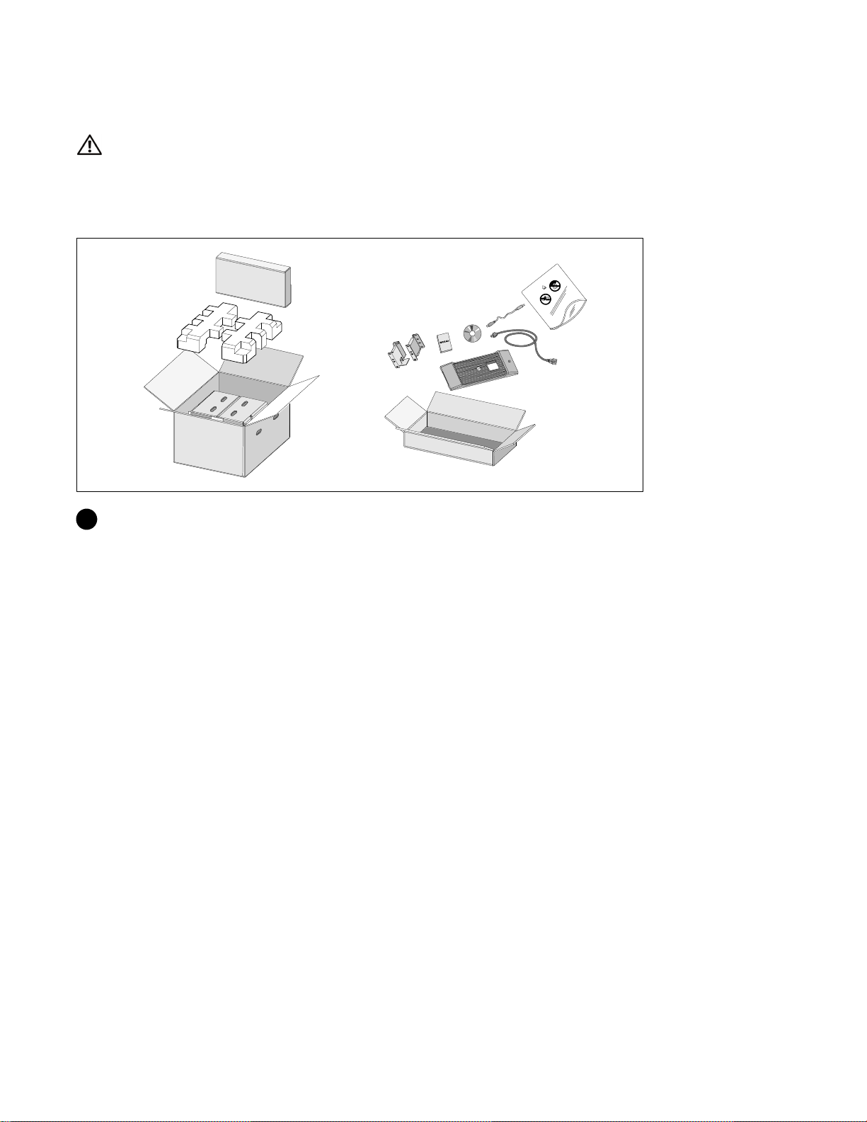
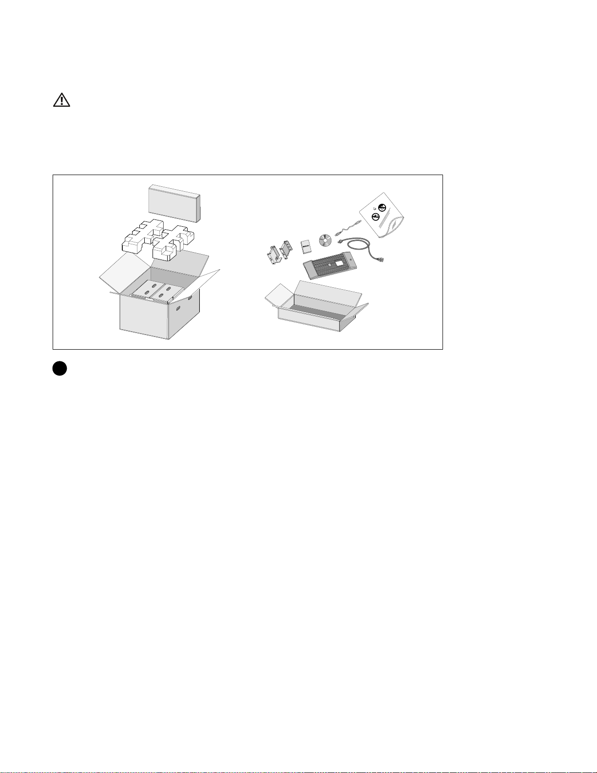
Unpacking the System
1 Open the outer carton and remove the accessories packaged with the cabinet.
Installation and Startup
|
5
Page 8

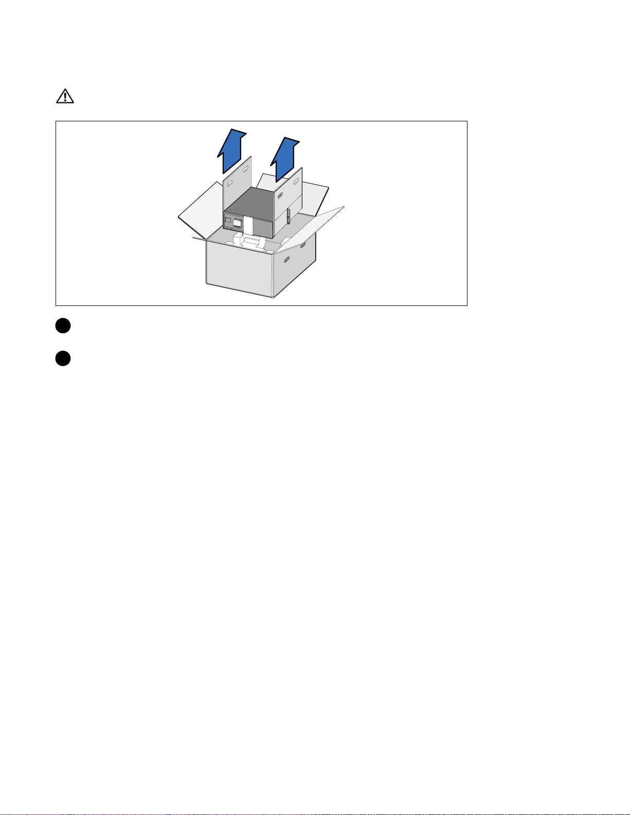
Lifting the Cabinet
CAUTION: The cabinet is heavy (36.9 kg/81.4 lb). Lifting the cabinets into the rack requires a minimum of two
people.
1 Withonepersononeachside,carefullyliftthecabinet out of the outer carton using the handles
on the cardboard and set it on a flat, stable surface.
2 Discard or recycle the packaging in a responsible manner, or store it for future use.
|
6
Installation and Startup
Page 9

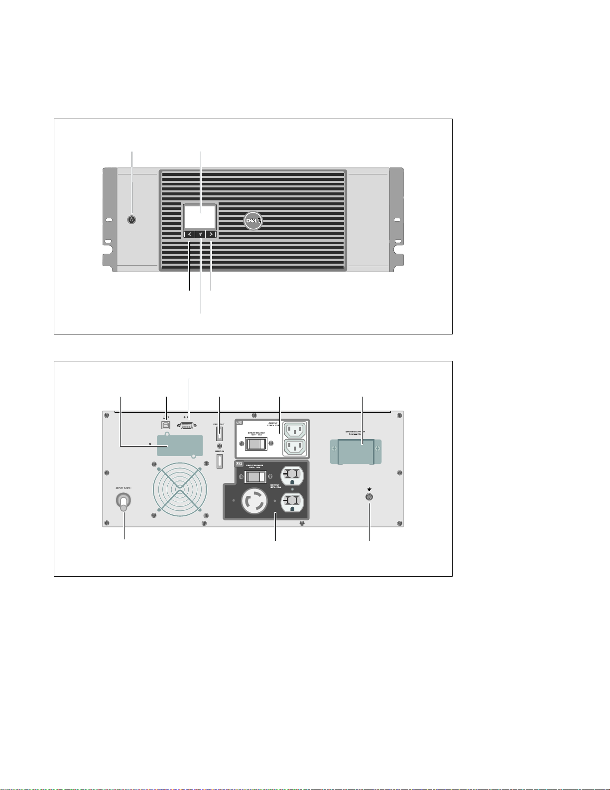
Identifying the UPS
This section shows a front and rear panel of the Dell Online Rack UPS. Refer to the Dell Online Rack
UPS 2700W User's Guide for all rear panel details.
On/Off Button
Scroll Button (Up or Back)
LCD Panel
Scroll Button (Down or Forward)
Select Button
Figure 1. The Dell Online Rack UPS Front Panel
Communication Bay
UPS
USB Port
RS-232 Port
REPO Ports
Two IEC 320-C13
Receptacles
(Load Segment 2)
EBM Connector
Cover/Strain Relief Bracket
2m, L5-30P Input
Cord
Figure 2. UPS Rear Panel (2700W, 120V Shown)
One L5-20 and Two 5-15/5-20
Receptacles
(Load Segment 1)
Ground Screw
Installation and Startup
|
7
Page 10
Rackmount Setup
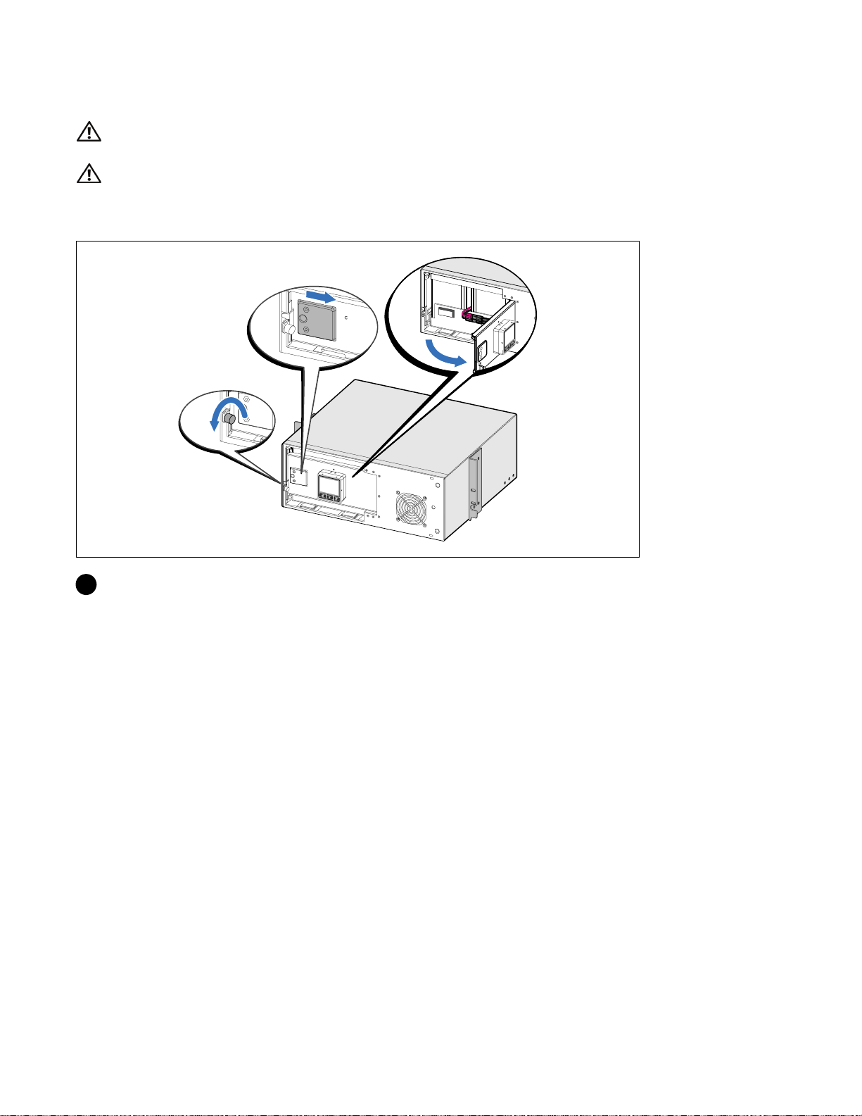
CAUTION: The cabinet is heavy (36.9 kg/81.4 lb): 1) Dell strongly recommends to remove the battery tray from
the UPS before lifting. 2) Lifting the cabinets into the rack requires a minimum of two people.
CAUTION: Removing the batteries should be performed or supervised by personnel knowledgeable about
batteries and the required precautions. Keep unauthorized personnel away from batteries.
Opening the Battery Cover
1 Loosen the thumbscrew on the metal battery cover, slide the cover to the right, and open.
|
8
Installation and Startup
Page 11
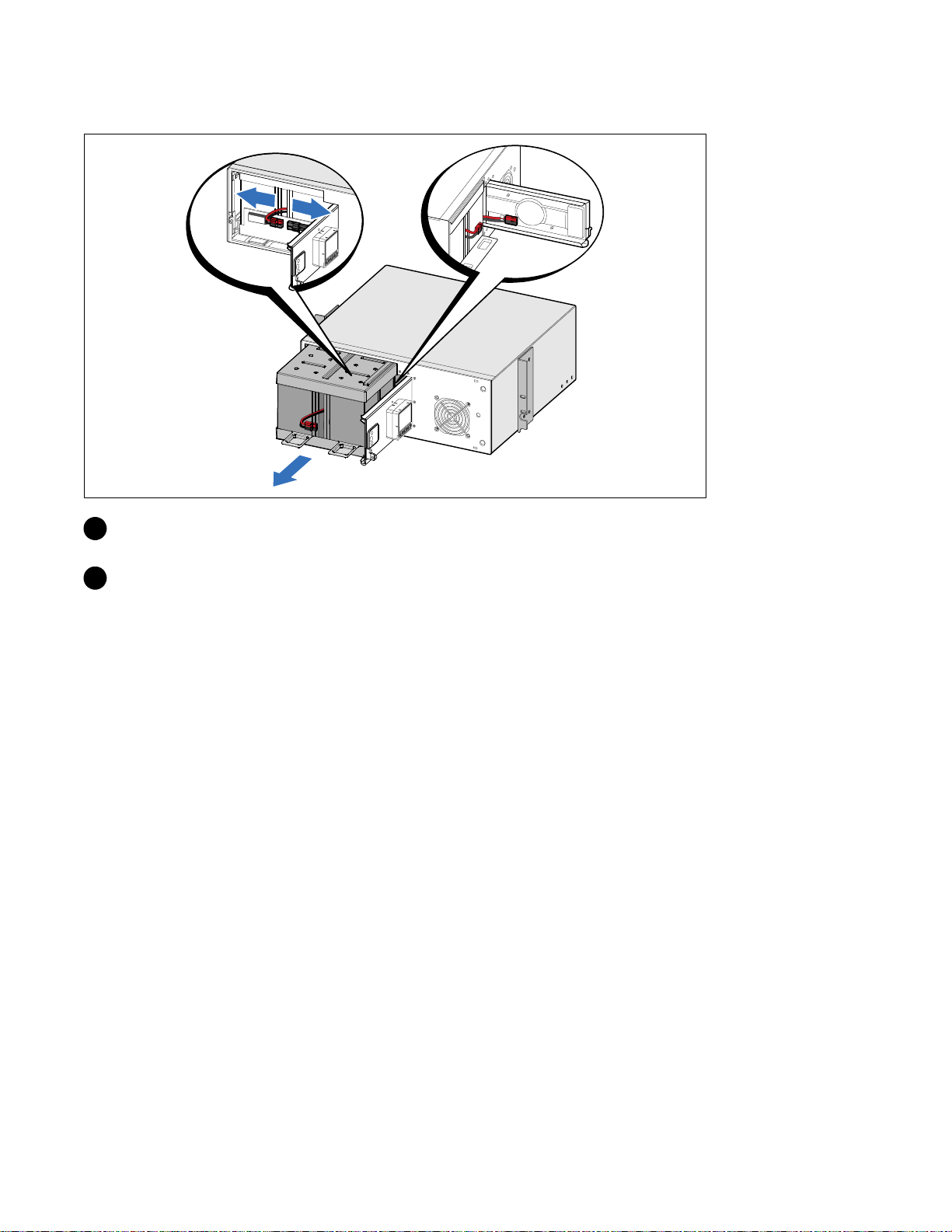
Removing the Battery Tray
2 Disconnect the battery connector and place the right battery connector in the battery door to
move it out of the way.
3 Pull the battery tray out using the plastic tabs and remove the battery tray.
Installation and Startup
|
9
Page 12
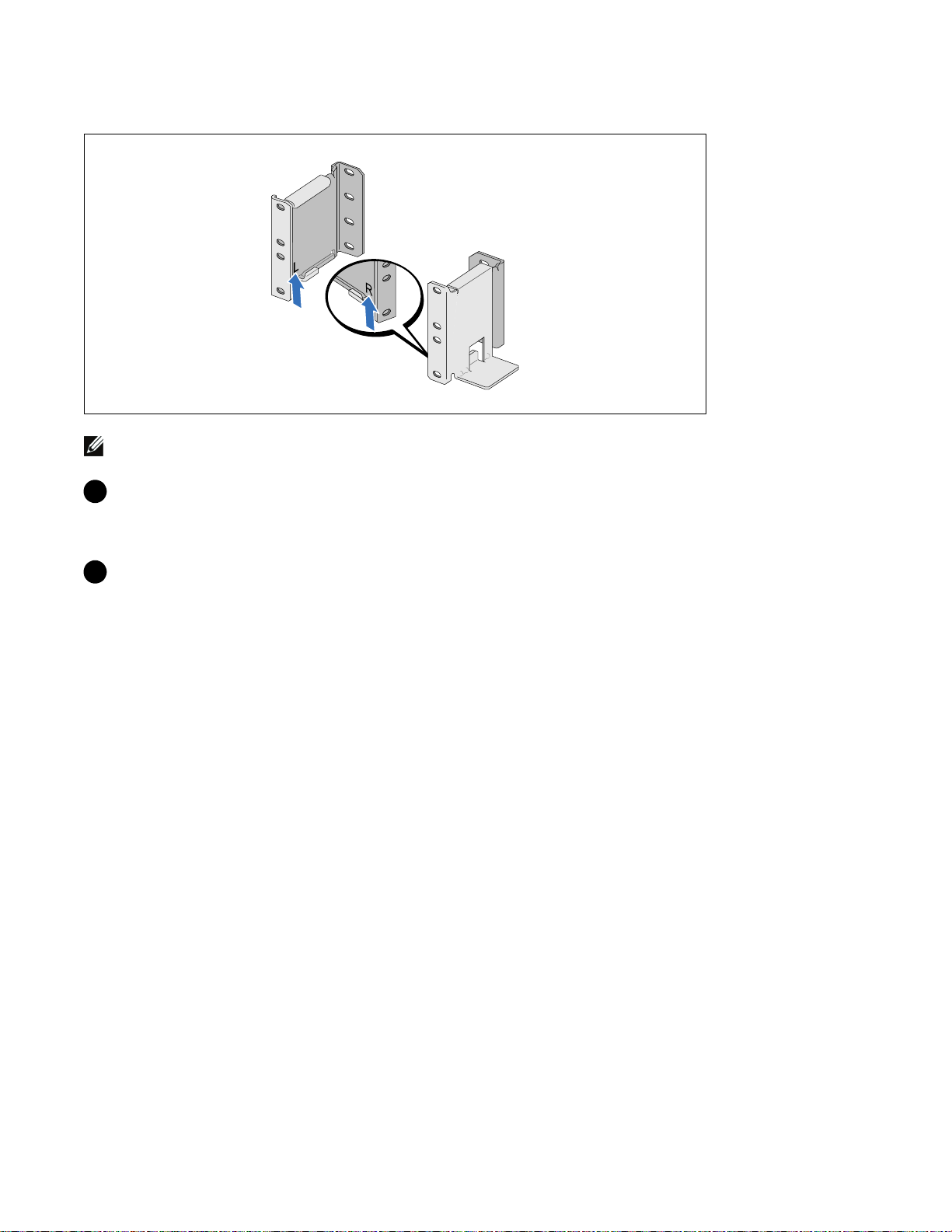
Positioning the Rails
NOTE: The instructions are the same for square-hole racks and unthreaded, round-hole racks. The rails fit both
rack styles. The round-hole rack is shown in the illustrations.
4 Select the proper holes in the rail for positioning the UPS in the desired location in the rack.
The rails should be located at the bottom of the 4U space allocated for the UPS or 3U for the
EBM.
5 Position the end of the left and right rails labeled L and R facing inward.
|
10
Installation and Startup
Page 13

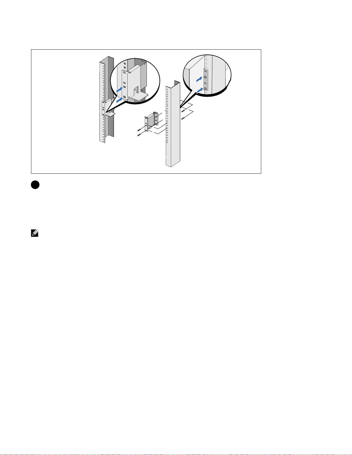
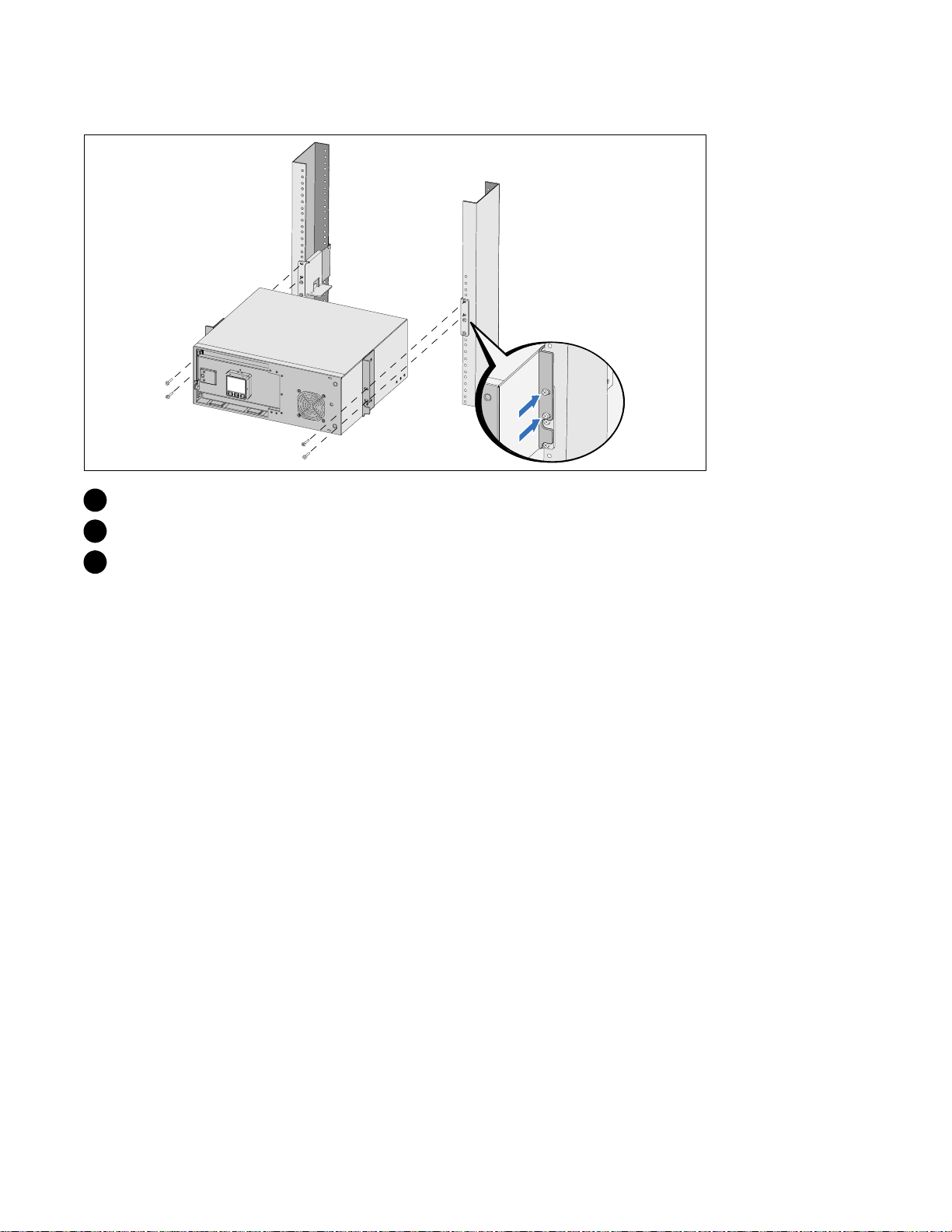
Attaching the Rails to the Rack
6 Attach the rails to the rack:
Adjust the rail so that the flanges fit outside the C-shaped vertical rail.
Secure the rail using the supplied #12-24 Phillips head screws (four for each rail). Use the bottom
two holes for the front of the rail. Use the second and fourth holes for the back of the rail.
NOTE:
If the vertical rail has square holes, use a square nut (not supplied) with the supplied #12-24
Phillips-head screw.
Installation and Startup
|
11
Page 14

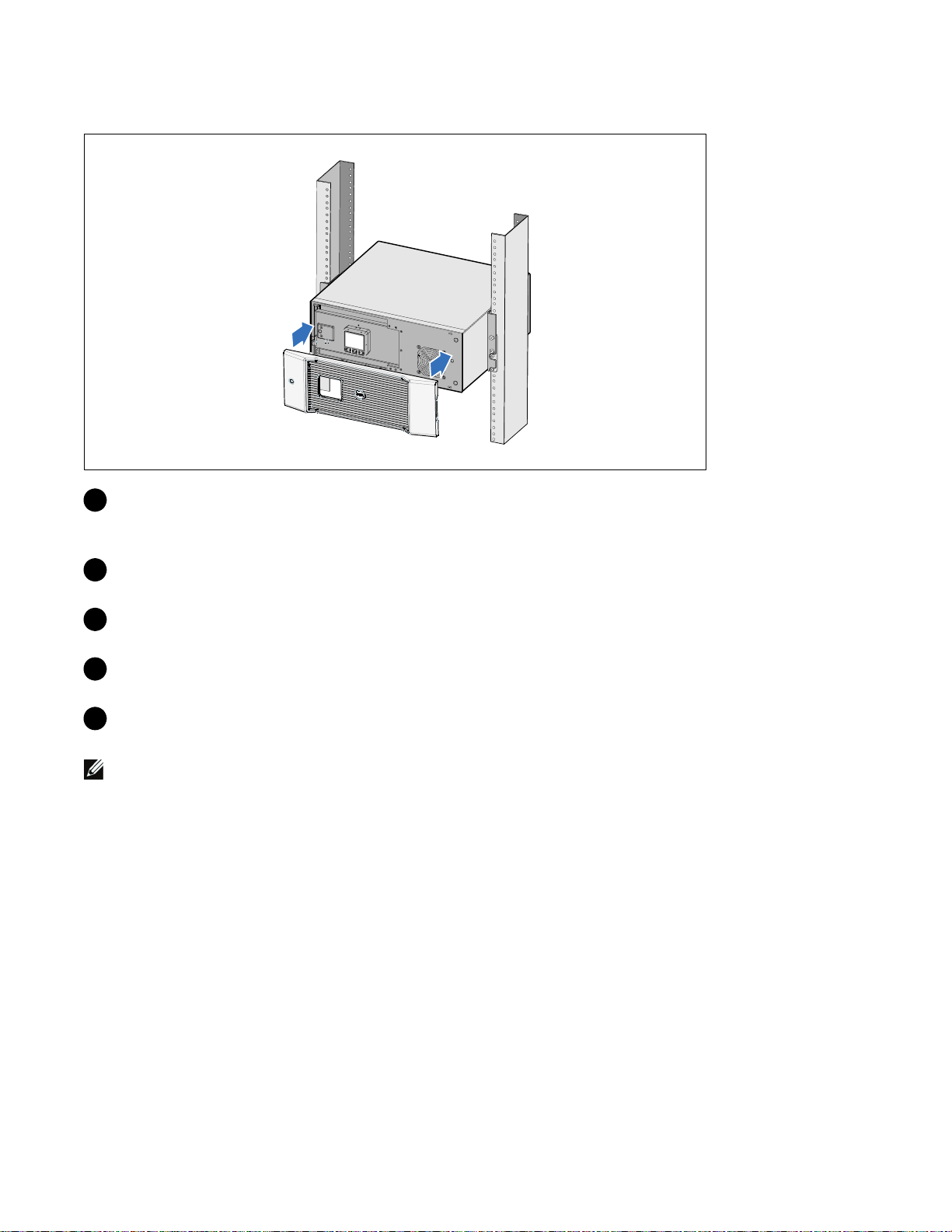
Installing and Securing the Cabinet
7 Slide the cabinet into the rack.
8 Secure the cabinet to the rack using the supplied #12-24 Phillips-head screws (two on each side).
9 Repeat for any additional cabinets.
12
|
Installation and Startup
Page 15

Installing the Battery Tray
NOTE: A small amount of arcing may occur when connecting the batteries. This is normal and does not damage
the unit or present any safety concern.
10 Remove the right battery connector from the door and connect the internal battery connector.
11 Close the metal battery cover.
Adjust the battery connector so that the door closes properly. Push the door slightly to the right
and then to left.
12 Tighten the thumbscrew.
Torque the screw to 0.7 Nm (6.2 lb in).
Installation and Startup
|
13
Page 16
Installing the UPS Front Cover
13 Install the UPS front cover.
Connecting the Equipment
1
If you plan to use Dell UPS Management Software, connect your computer to the USB port using
the supplied cable.
2 If your rack has conductors for grounding or bonding of ungrounded metal parts, connect the
ground cable (not supplied) to the ground bonding screw.
3 If an emergency power-off (disconnect) switch is required by local codes, see “Installing Remote
Emergency Power-off” (REPO) in the Dell Online Rack UPS 2700W User's Guide.
4 Plug the equipment to be protected into the UPS output receptacles, but do not turn on the
protected equipment.
Verify that the total equipment ratings do not exceed the UPS capacity to prevent an overload alarm.
NOTE:
|
14
Installation and Startup
Page 17
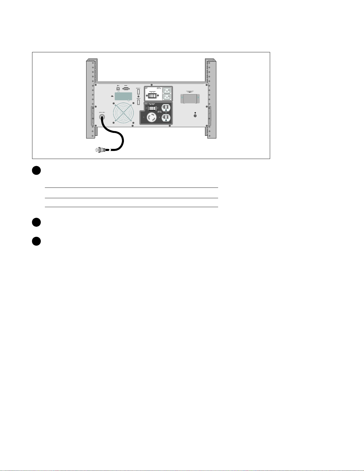
Connecting the Power Cord
5 Verify that the power input to the UPS has adequate upstream overcurrent protection:
Table 1. Minimum Upstream Circuit Breaker Rating
UPS Output Power
2700W 30A 20A 16A
120V 208V 230V
6 For models with a detachable power cord. Plug the detachable UPS power cord into the input
connector on the UPS rear panel.
7 Plug the UPS power cord into a power outlet.
Installation and Startup
|
15
Page 18
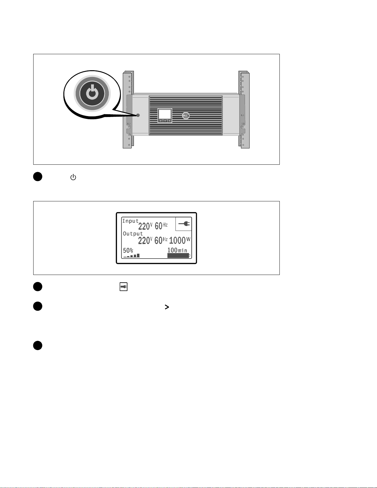
Starting the UPS
8 Press the button on the UPS front panel.
Completing the Startup
9 Verify that the Normal icon appears on the UPS status summary screen, indicating that the
UPS is operating normally and any loads are powered.
10 On the UPS status summary screen, press the button to check for active alarms or notices.
Resolve any active alarms before continuing. See “Troubleshooting” in the Dell Online Rack UPS
2700W User's Guide.
If there are no active alarms, a “No Active Alarms” message appears.
11 To change other factory-set defaults, see “Operation” in the Dell Online Rack UPS 2700W User's
Guide.
|
16
Installation and Startup
Page 19

Onduleur en Baie En Ligne Dellt
2700 W
Démarrer
avec votre système
www.dell.com | support.dell.com
K803N , H950N, J728N
H967N
Page 20

Remarques et avertissements
REMARQUE : Une REMARQUE indique des informations importantes qui vous aident à mieux utiliser votre logiciel.
MISE EN GARDE : Une MISE EN GARDE indique une situation dangereuse potentielle qui, si elle n'est pas évitée,
peut provoquer une blessure mineure ou modérée ou des dommages matériels.
AVERTISSEMENT : Un AVERTISSEMENT indique une situation dangereuse potentielle qui, si elle n'est pas évitée,
pourrait provoquer la mort ou une blessure.
DANGER : Un DANGER indique une situation dangereuse imminente qui, si elle n'est pas évitée, provoquera la
mort ou une blessure grave.
DANGER : Respectez les instructions suivantes pour aider à empêcher une situation dangereuse qui, si elle n'est
pas évitée, peut provoquer la mort ou des blessures graves :
S Cet onduleur contient des TENSIONS MORTELLES. Toutes les réparations et tous les entretiens
devront être effectués UNIQUEMENT PAR UN PERSONNEL D’ENTRETIEN AGRÉÉ. Aucune
pièce à l’intérieur de cet onduleur NE PEUT ÊTRE ENTRETENUE P A R L’UTILISATEUR.
Les informations figurant dans ce document sont soumises à modification sans préavis.
E 2009 Dell Inc. Tous droits réservés.
La reproduction de quelque manière que ce soit sans l’autorisation écrite de Dell Inc. est strictement interdite.
Marques commerciales utilisées dans ce texte : Dell et le logo DELL sont des marques commerciales de Dell Inc. ; Phillips est une marque
commerciale de Phillips Screw Company.
D’autres marques commerciales et noms commerciaux peuvent être utilisés dans ce document pour se référer à des entités revendiquant les
marques et les noms ou à leurs produits. Dell Inc. nie tout intérêt propriétaire dans les marques commerciales et les noms commerciaux qui
ne lui appartenant pas.
Julliet 2009
Page 21

Caractéristiques du système
Offrant une fiabilité et des performances remarquables, les avantages uniques de l'onduleur
comprennent :
S Conception en ligne avec sortie sinusoïdale pure. L'onduleur filtre et régule le courant CA entrant
et fournit un courant constant à votre équipement sans vider la batterie.
S Technologie en ligne double-conversion réelle à haute densité de puissance, indépendance à la
fréquence du secteur, et compatibilité avec un groupe électrogène.
S Mode de fonctionnement haute performance sélectionnable.
S Taille4U quiconvientàtoutebaiestandardde48cm(19”).
S Capacité de démarrage-sur-batterie pour alimenter l'onduleur même si le courant du secteur n'est
pas disponible.
S Temps d'exécution prolongé avec un Module de batterie externe (EBM) en option pour modèles
d'onduleur 2700 W.
S Commande d'arrêt d'urgence par les ports d'arrêt d'urgence distants (REPO).
S Deux ports de communication standards (port série DB-9 et USB).
S Carte de gestion de réseau Dell optionnelle avec capacités de communication améliorées pour une
protection et un contrôle accrus de l'alimentation électrique.
S Gestion avancée de l'alimentation électrique avec le Logiciel de gestion d'onduleur Dell pour des
coupures progressives et une surveillance de l'alimentation.
S Arrêt séquentiel et gestion de charge par des groupes de prises séparés appelés « segments de
charge ».
S Micrologiciel qui peut être facilement mis à niveau sans appeler le service technique.
S Certifié par des approbations d'organismes dans le monde entier.
Caractéristiques du système
|
19
Page 22
Trouver des informations
ATTENTION! Le document Informations sur la sécurité, l'environnement et la réglementation fournit des
informations importantes sur la sécurité et la réglementation.
Que recherchez-vous ?
S Le guide d'utilisation de mon onduleur
S Leguided'utilisationdemaCartedegestionde
réseau Del l
S Logiciel de gestion d'onduleur Dell
Trouvez-le ici
Disque de l'onduleur Dell
REMARQUE : Les mises à jour des documents et des
logiciels se trouvent sur
S Spécifications
S Comment configurer les paramètres de l'onduleur
S Comment identifier et résoudre des problèmes
S Comment installer un contrôle REPO
S Instructions de sécurité
S Informations sur la réglementation
S Informations sur le recyclage
S Informations sur la garantie
S Termes et conditions (États-Unis uniquement)
S Contrat de licence de l'utilisateur final
S Informations sur l'assistance Site Internet d'Assistance Dell — support.dell.com
Guide d'utilisation de l'onduleur Dell
Le guide d'utilisation est disponible sur le disque de
l'onduleur Dell et sur support.dell.com.
Informations sur la sécurité, l'environnement et la
réglementation
Informations sur l'assistance et la garantie Dell
support.dell.com.
REMARQUE : Sélectionnez votre région ou votre
segment commercial pour voir le site d'assistance
approprié.
20
|
Trouver des informations
Page 23
Installation et démarrage
ATTENTION! Avant de réaliser les procédures de ce document, lisez et suivez les instructions de sécurité et
les informations importantes sur la réglementation qui figurent dans votre document Informations sur la
sécurité, l'environnement et la réglementation.
Cette section décrit les étapes de configuration de votre système pour la première fois.
Déballage du système
1 Ouvrez le carton extérieur et retirez les accessoires emballés avec le module.
Installation et démarrage
|
21
Page 24
Levage du module
ATTENTION! Le module est lourd (36,9 kg/81.4 lb). Le levage des modules dans la baie exige deux personnes
au minimum.
1 Avec une personne de chaque côté, levez soigneusement le module hors du carton extérieur en
utilisant les poignées du carton et posez-le sur une surface plane et stable.
2 Jetez ou recyclez l'emballage d'une façon responsable, ou conservez-le pour une utilisation
ultérieure.
22
|
Installation et démarrage
Page 25
Identification de l'onduleur
Cette section montre un panneau avant et a rrière de l'onduleur Baie En Ligne Dell. Reportez-vous au
Guide d'Utilisation de l'Onduleur en Baie En Ligne 2700 W pour tous les détails sur le panneau arrière.
Bouton
Marche/Arrêt
Bouton de défilement
(haut ou arrière)
Panneau LCD
Bouton de défilement (bas ou avant)
Bouton de sélection
Figure 1. Panneau avant de l'onduleur Baie En Ligne Dell
communication de
Baie de
l'onduleur
Port USB
Port RS-232
Ports REPO
Deux prises CEI 320-C13
(Segment de charge 2)
Serre-câble/Couvercle du
connecteur EBM
Cordon d'entrée
L5-30P, 2 m
Une Prise L5-20 et Deux
Prises 5-15/5-20
(Segment de charge 1)
Figure 2. Panneau arrière de l'onduleur (2700W, 120V V représenté)
Visdemiseàla
terre
Installation et démarrage
|
23
Page 26

Configuration en baie
ATTENTION! Le module est lourd (36,9 kg/81.4 lb) : 1) Dell recommande fortement de retirer le plateau de
batteries de l'onduleur avant le levage. 2) Soulever les modules dans la baie exige deux personnes au
minimum.
ATTENTION! Le retrait des batteries doit être réalisé ou supervisé par du personnel connaissant les batteries
et les précautions requises. Maintenez le personnel non autorisé éloigné des batteries.
Ouverture du couvercle des batteries
1 Desserrez la vis à oreilles sur le couvercle métallique des batteries, faites glisser le couvercle vers la
droite et ouvrez.
|
24
Installation et démarrage
Page 27

Retrait du plateau des batteries
2 Débranchez le connecteur des batteries et placez le connecteur droit des batteries dans le
couvercledebatteriepourledéplacer.
3 Tirez le plateau des batteries en utilisant les languettes en plastique et retirez le plateau des
batteries.
Installation et démarrage
|
25
Page 28

Positionnement des Rails
REMARQUE: Les instructions sont les mêmes pour les baies à trous carrés et les baies à trous ronds non
filetés. Les rails s'adaptent aux deux styles de baies. La baie à trous ronds est représentée sur les illustrations.
4 Sélectionnez les bons trous dans le rail pour positionner l'onduleur à l'emplacement souhaité dans
la baie.
Les rails doivent être situés en bas de l'espace 4U alloué à l'onduleur ou 3U de l'EBM.
5 Positionnez l'extrémité des rails gauches et droits marquée L et R vers l'intérieur.
|
26
Installation et démarrage
Page 29
Fixation des rails à la baie
6 Fixez les rails à la baie :
Réglez le rail pour que les bords s'emboîtent à l'extérieur du rail vertical en forme de C.
Fixez le rail en utilisant les vis à tête Phillips n°12-24 fournies (quatre pour chaque rail). Utilisez
les deux trous inférieurs pour l'avant du rail. Utilisez les deuxième et quatrième trous pour l'arrière
du rail.
REMARQUE:
Phillips n°12-24 fournie.
Si le rail vertical a quatre trous carrés, utilisez un écrou carré (non fourni) avec la vis à tête
Installation et démarrage
|
27
Page 30
Installation et Fixation du Module
7 Glissezlemoduledanslabaie.
8 Fixez le module à la baie en utilisant les vis à tête Phillips n°12-24 fournies (deux de chaque côté).
9 Répétez la procédure pour des modules supplémentaires.
28
|
Installation et démarrage
Page 31

Installation du plateau des batteries
REMARQUE: Un petit arc électrique peut survenir lors du branchement des batteries. Ceci est normal,
n'endommage pas l'unité et ne présente aucun problème de sécurité.
10 Retirez le connecteur droit des batteries du couvercle et branchez le connecteur de batteries
internes.
11 Fermez le couvercle métallique des batteries.
Positionnez le connecteur des batteries pour que la porte se ferme correctement. Poussez la porte
doucement vers la droite, puis vers la gauche.
12 Serrez la vis à oreilles.
Serrezlavisàuncouplede0,7Nm(6,2lbin).
Installation et démarrage
|
29
Page 32

Installation du couvercle avant de l'onduleur
13 Installez le couvercle avant de l'onduleur.
Connexion de l'équipement
1
Si vous prévoyez d'utiliser le Logiciel de gestion d'onduleur Dell, connectez votre ordinateur au
port USB en utilisant le câble fourni.
2 Si votre châssis a des conducteurs pour la mise à la terre ou le soudage des pièces métalliques non
reliées à la masse, connectez le câble de masse (non fourni) sur lavisdeconnexionàlamasse.
3 Si un interrupteur d'arrêt (disjoncteur) d'urgence est requis par les réglementations locales, voir «
Installation d'un arrêt d'urgence distant » (REPO) dans le Guide d'Utilisation de l'Onduleur en Baie
En Ligne 2700 W.
4 Branchez l'équipement à protéger sur les prises de sortie de l'onduleur, mais ne mettez pas
l'équipement à protéger sous tension.
REMARQUE:
ne dépassent pas la capacité de l'onduleur.
|
30
Installation et démarrage
Pour éviter une alarme de surcharge, vérifiez que les valeurs nominales totales de l'équipement
Page 33

Connexion du cordon d'alimentation
5 Vérifiez que l'entrée d'alimentation vers l'onduleur possède une protection adéquate contre des
surintensités montantes :
Tableau 1. Valeur nominale minimale du disjoncteur amont
Puissance de sortie de
l'onduleur
2700 W 30 A 20 A 16 A
120 V 208 V 230 V
6 Pour des modèles avec cordon d'alimentation amovible. Branchez le cordon d'alimentation amovible
de l'onduleur au connecteur d'entrée sur le panneau arrière de l'onduleur.
7 Branchez le câble d’alimentation électrique de l’onduleur sur une prise de courant.
|
Installation et démarrage
31
Page 34

Démarrage de l'onduleur
8 Appuyez sur le bouton sur le panneau avant de l'onduleur.
Achèvement du démarrage
9 Vérifiez que l'icône Normal apparaisse sur l'écran de résumé d'état de l'onduleur, indiquant
que l'onduleur fonctionne normalement et que toutes les charges sont alimentées.
10 Sur l'écran de résumé d'état de l'onduleur, appuyez sur le bouton pour vérifier les notification et
les alarmes actives. Résolvez toutes les alarmes actives avant de continuer. Voir « Dépannage »
dans le Guide d'Utilisation de l'Onduleur en Baie En Ligne 2700 W.
Si aucune alarme n'est activée, un message « Aucune alarme active » a pparaîtra.
11 Pour changer d'autres valeurs d'usine par défaut, voir « Fonctionnement » dans le Guide
d'Utilisation de l'Onduleur en Baie En Ligne 2700 W.
|
32
Installation et démarrage
Page 35

Dellt Online Rack-UVS
2700 W
Erste Schritte
Mit Ihrem System
www.dell.com | support.dell.com
K803N , H950N, J728N
H967N
Page 36

Hinweise und Warnungen
HINWEIS: Ein HINWEIS macht auf eine wichtige Information aufmerksam, mit deren Hilfe Sie Ihre Software optimal
nutzen können.
ACHTUNG: ACHTUNG macht auf eine potenziell gefährliche Situation aufmerksam, die zu geringen oder mäßigen
Verletzungen oder Sachschäden führen kann, wenn sie nicht vermieden wird.
WARNUNG: WARNUNG macht auf eine potenziell gefährliche Situation aufmerksam, die zum Tod oder zu
Verletzungen führt, wenn sie nicht vermieden wird.
GEFAHR: GEFAHR macht auf eine unmittelbar gefährliche Situation aufmerksam, die zum Tod oder schweren
Verletzungen führt, wenn sie nicht vermieden wird.
GEFAHR: Beachten Sie die folgende Anweisung, um eine unmittelbar gefährliche Situation zu vermeiden, die zum
Tod oder zu schweren Verletzungen führen könnte:
S Diese USV führt LEBENSGEFÄHRLICHE SPANNUNG. Sämtliche Reparatur-- und Wartungsarbeiten
dürfen NUR VON BEFUGTEM WARTUNGSPERSONAL durchgeführt werden. Im Inneren der
USV sind KEINE VOM BENUTZER WARTBAREN TEILE vorhanden.
Unangekündigte Änderungen der Angaben in diesem Dokument vorbehalten.
E 2009 Dell Inc. Alle Rechte vorbehalten.
Die Vervielfältigung, gleich welcher Art, ist ohne schriftliche Genehmigung von Dell Inc. strengstens untersagt.
In diesem Text verwendete Marken: Bei Dell und dem DELL--Logo handelt es sich um Marken der Dell Inc.; Phillips ist eine eingetragene
Handelsmarke der Phillips Screw Company.
In diesem Dokument können weitere Marken und Handelsnamen verwendet werden, die sich entweder auf die Personen beziehen, die diese
Marken und Namen für sich beanspruchen, oder auf deren Produkte. Dell Inc. verzichtet auf sämtliche gewerblichen Eigentumsrechte an
Marken und Handelsnamen, bei denen es sich nicht um eigene Marken und Handelsnamen handelt.
Juli 2009
Page 37

Systemmerkmale
Die herausragende Leistung und Zuverlässigkeit sind nur einige der einzigartigen Vorteile der
USV-Anlagen. Sie bieten zudem:
S Online USV-Design mit reinem Sinusausgang. Die USV filtert und regelt eingehenden
Wechselstrom und sorgt für eine gleichförmige Versorgung Ihrer Anlagen mit Strom, ohne Energie
vonderBatteriezuziehen.
S Echte Online-Doppelwandlertechnologie mit hoher Leistungsdichte, Unabhängigkeit der
Netzfrequenz und Generatorkompatibilität.
S Auswählbarer Hocheffizienzbetrieb.
S 4 U -Größe, die in jedes Standard 48 cm-Gestell passt.
S Starten der Anlage im Batteriebetrieb zum Versorgen der USV mit Strom, selbst wenn kein
Netzstrom zur Verfügung steht.
S Erweiterte Laufzeit mit optionalem Externen Batteriemodul (EBM) für 2700 W USV-Modelle.
S Notausschaltungssteuerung über die REPO-Schnittstellen (Remote Emergency Power Off).
S Serienmäßige Ausstattung mit zwei Kommunikationsschnittstellen (USV-Schnittstelle und serielle
DB-9-Schnittstelle).
S Optionale Dell Netzwerkmanagementkarte mit erweiterten Kommunikationsmöglichkeiten für
verbesserten Leistungsschutz und Kontrolle.
S Erweiterte Stromüberwachung mit der Dell USV Management Software für allmähliches
Herunterfahren und Stromüberwachung.
S Sequenzielle Abschaltung und Lastenmanagement durch separate Anschlussgruppen (sogenannte
Lastsegmente).
S Firmware, die sich einfach und ohne Wartungsdienst aktualisieren lässt.
S Entspricht allen einschlägigen Normen weltweit.
Systemmerkmale
|
35
Page 38

Auffinden von Informationen
f
ACHTUNG: Im Dokument Informationen zu Sicherheit, Umweltschutz und Ordnungsvorschriften finden Sie
wichtige Sicherheitshinweise und Informationen zu gesetzlichen Bestimmungen.
Was suchen Sie?
S Die Benutzeranleitung für meine USV
S Die Benutzeranleitung für die Dell
Netzwerkmanagementkarte
S Dell USV Management Software
Hier finden Sie es
Die Disk
ür die Dell USV
HINWEIS: Dokumente und Softwareaktualisierungen
finden Sie unter
S Technische Daten
S Anleitung zum Konfigurieren der
USV-Einstellungen
S Behebung von Fehlern und Lösung von Problemen
S Installation der REPO-Steuerung
S Sicherheitshinweise
S Informationen über Ordnungsvorschriften
S Recycling-Informationen
S Garantieerklärung
S AGB (nur USA )
S Lizenzvereinbarung für Endbenutzer
S Supportinformationen Dell Support-Webseite - support.dell.com
Benutzeranleitung der Dell USV
Die Benutzeranleitung finden Sie auf der Disk zu der
Dell USV und auch unter support.dell.com.
Informationen zu Sicherheit, Umweltschutz und
Ordnungsvorschriften
Informationen zu Garantie und Support von Dell
support.dell.com.
HINWEIS: Wählen Sie Ihre Region bzw. Ihre Branche
aus, um die geeignete Support-Website aufzurufen.
|
36
Auffinden von Informationen
Page 39

Installation und Inbetriebnahme
ACHTUNG: Vor der Ausführung der Verfahren in diesem Dokument lesen und befolgen Sie b itte die
Sicherheitshinweise und wichtigen Informationen zu Ordnungsvorschriften in Ihrem Dokument über
Informationen zu Sicherheit, Umweltschutz und Ordnungsvorschriften.
In diesem Abschnitt werden die Schritte für die Erstkonfiguration I hres Systems beschrieben.
Auspacken des Systems
1 Öffnen Sie den äußeren Karton, und nehmen Sie die mit dem Gehäuse zusammen verpackten
Zubehörteile heraus.
Installation und Inbetriebnahme
|
37
Page 40

Gehäuse heben
:Das Gehäuse ist schwer (36,9 kg). Zum Heben des Gehäuses in das Gestell sind mindestens zwei Personen
erforderlich.
1 Heben Sie das Gehäuse mit einer Person auf jeder Seite mit den Griffen am Karton vorsichtig aus
dem äußeren Karton heraus, und setzen Sie es auf einer flachen, stabilen Unterlage ab.
2 Entsorgen oder recyceln Sie die Verpackung in umweltbewusster Weise, oder bewahren Sie sie für
denspäterenGebrauchauf.
38
|
Installation und Inbetriebnahme
Page 41

Beschreibung der USV
In diesem Abschnitt wird die Vorder- und Rückansicht der Dell Online Rack USV angezeigt. Alle
Einzelheiten zur Rückseite finden Sie in der Benutzeranleitung für das Dell Online Rack UPS 2700 W.
Ein-/Aus-Schalter
Bildlauftaste (aufwärts
oder rückwärts)
LCD-Anzeige
Bildlauftaste
(abwärts oder vorwärts)
Auswahltaste
Abbildung 1. Die Vorderseite der Dell Online Rack USV
Kommunikationssch
acht der USV
USB-Anschluss
RS-232-Schnittstelle
REPO-Schnittstellen
Zwei IEC
320-C13-Anschlussdosen
(Lastsegment 2)
EBM-Anschlussabdeckung/
Druckausgleichsklammer
L5-30P-Eingangskabel
2m,
Ein L5-20 und zwei 5-15/5-20
Anschlussdosen
(Lastsegment 1)
Abbildung 2. Rückseite der USV (2700 W, 120 V abgebildet)
Erdungsschraube
Installation und Inbetriebnahme
|
39
Page 42

Rackmontage
:Das Gehäuse ist schwer (36,9 kg). 1) Dell empfiehlt vor dem Anheben ausdrücklich das Entfernen des
Batterieträgers aus der USV. 2) Zum Heben des Gehäuses in das Gestell sind mindestens zwei Personen
erforderlich.
:Die Entfernung der Batterien sollte unter Befolgung der erforderlichen Sicherheitsvorkehrungen durch
fachkundiges Personal erfolgen oder beaufsichtigt werden. Nicht ausreichend geschultem Personal ist der
Zugang zu den Batterien zu verwehren.
Öffnen der Batterieabdeckung
1 Lösen Sie die Rändelschraube auf der metallenen Batterieabdeckung, schieben Sie die Abdeckung
nach rechts und öffnen Sie sie.
|
40
Installation und Inbetriebnahme
Page 43

Entfernen des Batterieträgers
2 Entfernen Sie den Batterieanschluss, und platzieren Sie den rechten Batterieanschluss in der
Batterieklappe, damit er nicht stört.
3 Ziehen Sie den Batterieträger mit den Kunststofflaschen heraus, und entfernen Sie ihn.
Installation und Inbetriebnahme
|
41
Page 44

Positionierung der Schienen
HINWEIS: Für Gestelle mit quadratischen Öffnungen und Racks mit runden Öffnungen ohne Gewinde gelten die
gleichen Anweisungen. Die Schienen passen zu beiden Gestellarten. Auf den Abbildungen ist das Gestell mit
den runden Öffnungen zu sehen.
4 Wählen Sie die korrekten Öffnungen in der Schiene aus, um die USV wie gewünscht im Rack zu
positionieren.
Die Schienen sollten unten an dem 4 U-Platz angeordnet sein, der der USV zugewiesen wurde,
bzw. am 3 U bei der EBM.
5 Richten Sie das Ende der linken und rechten Schiene mit der Aufschrift L und R nach innen aus.
|
42
Installation und Inbetriebnahme
Page 45

Anbringen der Schienen am Gestell
6 Bringen Sie die Schienen am Gestell an:
Stellen Sie die Schiene so ein, dass die Flansche außen mit der C-förmigen senkrechten Schiene
zusammenpassen.
Sichern Sie die Schiene mithilfe der enthaltenen #12-24 Philips-Rändelschrauben (vier für jede
Schiene). Verwenden Sie die unteren zwei Löcher für die Schienenvorderseite. Verwenden Sie das
zweite und vierte Loch für die Schienenrückseite.
HINWEIS:
mit dem enthaltenen #12-24 Phillips-Schraubenschlüssel verwenden.
Wenn die senkrechte Schiene rechteckige Löcher aufweist, die rechteckige Nut (nicht enthalten)
|
Installation und Inbetriebnahme
43
Page 46

Installation und Sicherung des Gehäuses
7 Schieben Sie das Gehäuse in das Gestell.
8 Sichern Sie das Gehäuse am Gestell mithilfe der enthaltenen #12-24 Philips-Rändelschrauben
(zwei auf jeder Seite).
9 Wiederholen Sie den Vorgang für weitere Gehäuse.
|
44
Installation und Inbetriebnahme
Page 47

Installation des Batterieträgers
HINWEIS: Bei der Verbindung der Batterien kann es zu einem kleinen Lichtbogen kommen. Das ist normal und
schadet weder der Anlage noch stellt es ein Sicherheitsrisiko dar.
10 Entfernen Sie den rechten Batterieanschluss von der Klappe, und schließenSiedeninternen
Batterieanschluss an.
11 Schließen Sie die metallene Batterieabdeckung.
Passen Sie den Batterieanschluss so an, dass sich die Tür gut schließen lässt. Drücken Sie die Tür
leicht nach rechts und dann nach links.
12 Ziehen Sie die Rändelschraube fest.
Drehen Sie die Schraube mit einem Drehmoment von 0,7 N·m (6,2 lb in) wieder ein.
Installation und Inbetriebnahme
|
45
Page 48

Installation der vorderen USV-Abdeckung
13 Installieren Sie die vordere USV-Abdeckung.
Anschließen der Anlage
1
Sofern Sie die Benutzung der Dell USV Management Software planen, schließen Sie Ihren
Computer mit dem beiliegenden Kabel an die USB-Schnittstelle an.
2 Falls Ihr Gestell über Erdungsleitungen oder Leitungen zum Erden nicht geerdeter Metallteile
verfügt, das Erdungskabel (nicht enthalten) an die Erdungsschraube anschließen.
3 Falls die örtliche Gesetzgebung einen Not-Aus-Schalter (Sicherung) vorschreibt, siehe unter
„Installieren der Notausschaltsteuerung“ (REPO) in der Benutzeranleitung für das Dell Online
Rack UPS 2700 W.
4 Stecken Sie Stecker der zu schützenden Geräte in die Ausgangsanschlüsse der USV ein, aber
schalten Sie die geschützten Geräte noch nicht ein.
HINWEIS:
angeschlossenen Geräte die Kapazität der USV nicht überschreitet.
|
46
Um einen Überlastalarm zu vermeiden, vergewissern Sie sich, dass die Gesamtnennleistung aller
Installation und Inbetriebnahme
Page 49

Anschließen des Netzkabels
5 Vergewissern Sie sich, dass der Stromeingang der USV mit einem angemessenen Schutz gegen
Spannungsspitzen ausgestattet ist:
Tabelle 1. Mindestnennstrom der Überstromsicherung
USV-Ausgangsleistung
2700 W 30A 20A 16A
120V 208V 230V
6 Bei Modellen mit abnehmbarem Netzkabel. Stecken Sie das abnehmbare Netzkabel der USV in den
Eingangsanschluss auf der Rückseite der USV ein.
7 Stecken Sie das USV-Netzkabel in eine Steckdose ein.
|
Installation und Inbetriebnahme
47
Page 50

Starten der USV
8 Drücken Sie die Taste auf der Vorderseite der USV.
48
|
Installation und Inbetriebnahme
Page 51

Abschluss des Startvorgangs
9 Vergewissern Sie sich, dass das Symbol für „Normal“ auf dem Bildschirm der
USV-Statusübersicht angezeigt wird. Hierdurch wird angezeigt, dass die USV ordnungsgemäß
funktioniert und dass alle angeschlossenen Lasten mit Strom versorgt werden.
10 Wählen Sie im Bildschirm mit der USV-Statusübersicht die Taste ,umzuprüfenobaktive
Warnmeldungen oder ein aktive Hinweise vorliegen. Lösen Sie alle aktiven Warnmeldungen,
bevor Sie den Vorgang fortsetzen. Siehe „Fehlerbehebung“ in der Benutzeranleitung für das Dell
Online Rack UPS 2700 W.
Falls keine Warnmeldungen aktiv sind, wird die Meldung „Keine aktiven
Warnmeldungen“ angezeigt.
11 Für die Änderung anderer werkseitiger Standardeinstellungen siehe „Betrieb“ in der
Benutzeranleitung für das Dell Online Rack UPS 2700 W.
Installation und Inbetriebnahme
|
49
Page 52

50
|
Installation und Inbetriebnahme
Page 53

Онлайновый ИБП Dellt
для установки в стойке
2700 Вт
Начало работы
c вашей системой
www.dell.com | support.dell.com
K803N , H950N, J728N
H967N
Page 54

Примечания и предупреждения
ПРИМЕЧАНИЕ: Пометка ПРИМЕЧАНИЕ указывает на важную информацию, которая поможет
вам более эффективно использовать свое программное обеспечение.
ВНИМАНИЕ: Пометка ВНИМАНИЕ указывает на потенциально опасную ситуацию, которая,
если ее не избежать, может привести к травмам легкой и средней степени тяжести или к
повреждению имущества.
ПРЕДУПРЕЖДЕНИЕ: Пометка ПРЕДУПРЕЖДЕНИЕ указывает на потенциально опасную
ситуацию, которая, если ее не избежать, может привести к травме или летальному исходу.
ОПАСНОСТЬ: Пометка ОПАСНОСТЬ указывает на ситуации, в которых существует
непосредственная угроза, которая, если ее не избежать, приведет к серьезной травме или
летальному исходу.
ОПАСНОСТЬ: Следуйте приведенным ниже инструкциям, позволяющим предупредить
непосредственную угрозу, которая, если ее не избежать, приведет к серьезной травме или
летальному исходу:
S В устройстве ИБП некоторые узлы находятся под СМЕРТЕЛЬНО ОПАСНЫМ
НАПРЯЖЕНИЕМ. Все работы по ремонту и обслуживанию должны выполняться
ТОЛЬКО УПОЛНОМОЧЕННЫМ ОБСЛУЖИВАЮЩИМ ПЕРСОНАЛОМ.ВИБПНЕТ
УЗЛОВ, ОБСЛУЖИВАЕМЫХ ПОЛЬЗОВАТЕЛЕМ.
Информация в настоящем документе может быть изменена без предварительного уведомления.
E 2009 Dell Inc. Все права защищены.
Воспроизведение данного документа любым способом без письменного разрешения компании Dell Inc. категорически
запрещено.
Торговые знаки, используемые в данном тексте: Dell и логотип DELL являются торговыми знаками компании Dell Inc.;
Phillips является зарегистрированным торговым знаком Phillips Screw Company.
Прочие торговые знаки и торговые марки могут использоваться в данном документе для ссылки на организации,
предъявляющие права на эти знаки и марки или на соответствующие товары. Dell Inc. отказывается от любого права
собственности на какие-либо торговые знаки или торговые марки, кроме своих собственных.
Июль 2009 г.
Page 55

Функции системы
Вот уникальные преимущества, обеспечивающие исключительную эффективность и
надежность ИБП:
S Онлайн ИБП с чистой синусоидой на выходе. ИБП фильтрует входной переменный
ток и управляет им и обеспечивает стабильное питание вашего оборудования, не
разряжая батарею.
S Технология двойного преобразования с высокой плотностью мощности, независимой
от сети частотой тока и возможностью совместной работы с генератором.
S Выбираемый пользователем режим высокой эффективности.
S Размер 4U , который соответствует любой стандартной стойке 48 см.
S Функция запуска от батареи используется для питания ИБП даже при отсутствии
питания от электросети.
S Увеличенное время работы при помощи дополнительного модуля Модуль внешней
батареи (МВБ) для моделей ИБП 2700 Вт.
S Управление аварийным выключением через порты дистанционного аварийного
отключения (REPO).
S Два стандартных коммуникационных порта (USB и последовательный порт DB-9).
S Дополнительная Карта сетевого управления Dell с усовершенствованными
коммуникационными возможностями улучшает защиту питания и его мониторинг.
S Усовершенствованное управление питанием при помощи ПО Программа управления
ИБП Dell обеспечивает корректное выключение нагрузки и мониторинг
электропитания.
S Последовательное выключение и управление нагрузкой при помощи раздельных
групп разъемов, называемых сегментами нагрузки.
S Легко обновляемое встроенное программное обеспечение; для обновления нет
необходимости обращаться в службу технической поддержки.
S Утверждены международными организациями.
Функции системы
|
53
Page 56

Поиск информации
ВНИМАНИЕ: Документ Информация о технике безопасности, охране окружающей
среды и нормативная информация содержит важную информацию о технике
безопасности и нормативную информацию.
Что вы ищете?
S Руководство пользователя для моего ИБП
S Руководство пользователя для карты Карта
сетевого управления Dell
S Программа управления ИБП Dell
Вы найдете это здесь
Диск ИБП Dell
ПРИМЕЧАНИЕ: Документация и обновленные
версии ПО можно найти на сайте
support.dell.com.
S Спецификации
S Как конфигурировать настройки ИБП
S Как находить и устранять неисправности и
решать проблемы
S Как установить управление REPO
S Инструкции по технике безопасности
S Нормативная информация
S Информация об утилизации
S Информация о гарантии
S Условия и положения (только для США)
S Лицензионное соглашение с конечным
пользователем
S Информация о поддержке Веб-сайт техподдержки Dell —
Руководство пользователя ИБП Dell
Руководство пользователя доступно на диске
support.dell.com.
Информация о технике безопасности, охране
окружающей среды и нормативная
информация
Информация о гарантии и поддержке Dell
support.dell.com
ПРИМЕЧАНИЕ: Выберите свой регион или
сегмент бизнеса, чтобы увидеть
соответствующий сайт поддержки.
54
|
Поиск информации
Page 57

Установка и запуск
ВНИМАНИЕ: Перед выполнением процедур, описанных в данной документации,
прочтите и выполните инструкции по технике безопасности и ознакомьтесь с важной
нормативной информацией, которая содержится в документе Информация о технике
безопасности, охране окружающей среды и нормативная информация.
В данном разделе описываются этапы настройки системы в первый раз.
Распаковка системы
1 Откройте внешнюю картонную коробку и достаньте из нее принадлежности,
упакованные вместе с корпусом.
Установка и запуск
|
55
Page 58

Подъем корпуса
ВНИМАНИЕ: Корпус тяжелый (36,9 кг). Для подъема корпуса на стойку требуется не
менее двух человек.
1 Два человека (по одному человеку с каждой стороны) должны осторожно вынуть
корпус из картонной упаковки за ручки на картоне и установить его на ровной
устойчивой поверхности.
2 Выбросьте или утилизируйте упаковку согласно правилам или сохраните ее для
будущего использования.
56
|
Установка и запуск
Page 59

Описание ИБП
В данном разделе показаны передняя и задняя панели ИБП Стойка для онлайнового
Руководство пользователя онлайнового ИБП Dell 2700 Вт при установке в
стойке, чтобы получить подробную информацию о задней панели.
Кнопка
Вкл./Выкл.
Кнопка пролистывания
(вверх или назад)
Рис. 1. Передняя панель ИБП Стойка для онлайнового ИБП Dell
Жидкокристаллическая
панель
Кнопка пролистывания
(вниз или вперед)
Кнопка выбора
Установка и запуск
|
57
Page 60

Коммуникационн
ый отсек блока
бесперебойного
питания
Порт USB
Порт RS-232
Порты REPO
Два гнезда IEC 320-C13
(Сегмент нагрузки 2)
Крышка разъема
МВБ/Скоба натяжения
Входной шнур
L5-30P, 2 метра
Одно гнездо L5-20 и два
гнезда 5-15/5-20
(Сегмент нагрузки 1)
Рис. 2. Задняя панель ИБП (показана модель 2700 Вт, 120 В)
Болт заземления
58
|
Установка и запуск
Page 61

Вариант установки в стойке
ВНИМАНИЕ: Корпус тяжелый (36,9 кг): 1) Dell настоятельно рекомендует перед
подъемом извлечь блок батареи из ИБП. 2) Для подъема корпуса на стойку требуется
не менее двух человек.
ВНИМАНИЕ: Извлечение батарей должно осуществляться или контролироваться
персоналом, хорошо знающим батареи и требования техники безопасности.
Не допускайте к батареям посторонних.
Открытие крышки батареи
1 Ослабьте винт на металлической крышке батарей, отодвиньте крышку вправо
и откройте.
Установка и запуск
|
59
Page 62

Извлечение блока батареи
2 Отсоедините разъемы батареи и поместите правый разъем батареи на дверцу,
чтобы он не мешал.
3 Выдвиньте блок батарей, используя пластиковые ушки, и извлеките его.
|
60
Установка и запуск
Page 63

Установка на направляющие
Примечание: Инструкции по работе со стойками с квадратными отверстиями и стойками с
круглыми безрезьбовыми отверстиями одинаковые. Направляющие подходят для обоих
видов стоек. Стойка с круглыми отверстиями показана на рисунке.
4 Выберите надлежащие отверстия в направляющих для размещения ИБП в
желаемом месте стойки.
Направляющие должны находиться на нижней части пространства 4U, выделенного
для ИБП, или пространства 3U, выделенного для МВБ.
5 Поместите концы правой и левой направляющих с меткамиLиRвовнутрь.
Установка и запуск
|
61
Page 64

Крепление направляющих к стойке
6 Прикрепите направляющие к стойке:
Установите направляющую таким образом, чтобы фланцы зашли за вертикальную
рейку в форме буквы C.
Закрепите направляющую при помощи винтов №12-24 с головкой Phillips, которые
входят в комплект поставки (четыре на каждую направляющую). Для передней
части направляющей используйте два нижних отверстия. Используйте второе и
четвертое отверстия для задней части направляющей.
Примечание:
квадратную гайку (в комплект поставки не входит) и винт №12-24 с головкой Phillips (входит в
комплект поставки).
|
62
Установка и запуск
Если в вертикальной стойке отверстия квадратной формы, используйте
Page 65

Установка и фиксация корпуса
7 Задвиньте корпус в стойку.
8 Прикрепите корпус к стойке при помощи винтов №12-24 с головкой Phillips (входят в
комплект поставки) (по два с каждой стороны).
9 Повторите эту процедуру для всех дополнительных корпусов.
Установка и запуск
|
63
Page 66

Установка блока батарей
Примечание: При подключении батарей возможно незначительное искрение. Это
нормальное явление; оно не повреждает ИБП и не является опасным.
10 Удалите правый разъем батареи с дверцы и присоедините разъем внутренней
батареи.
11 Закройте металлическую крышку батарей.
Расположите разъем батарей таким образом, чтобы крышка закрылась правильно.
Надавите на крышку слегка вправо, а затем влево.
12 Затяните винт.
Затяните винт с усилием 0,7 Нм (6,2 фунта на дюйм).
|
64
Установка и запуск
Page 67

Установка передней крышки ИБП
13 Установите переднюю крышку ИБП.
Подключение оборудования
1
Если вы планируете использовать Программа управления ИБП Dell, подключите
свой компьютер к USB-порту при помощи прилагающегося кабеля.
2 Если стойка оснащена проводниками для заземления или контакта с
незаземленными металлическими деталями, подсоедините кабель заземления
(не входит в комплект) к винту заземления.
3 Если местные нормативы требуют аварийного (отключающего) выключателя
питания, см. Руководство пользователя онлайнового ИБП Dell 2700 Вт при установке
, раздел "Установка дистанционного аварийного выключения питания"
(REPO).
4 Подключите оборудование, которое необходимо предохранить от скачков
напряжения, к выходным гнездам ИБП, но не включайте это оборудование.
Примечание:
потребителей не превышает мощность ИБП.
Во избежание сигнала перегрузки убедитесь, что общая паспортная мощность
Установка и запуск
|
65
Page 68

Подключение шнура питания
5 Убедитесь, что вход питания ИБП имеет соответствующую защиту от верхней
перегрузки по току:
Таблица 1. Минимальный номинал вышестоящего выключателя
Выходная мощность
ИБП
2700 Вт 30 A 20 A 16 A
120 В 208 В 230 В
6 Для моделей со съемным шнуром питания. Включите отсоединяемый шнур питания
ИБП во входящий разъем на задней панели ИБП.
7 Вставьте шнур питания ИБП в розетку электросети.
|
66
Установка и запуск
Page 69

Включение ИБП
8 Нажмите кнопку на передней панели ИБП.
Установка и запуск
|
67
Page 70

Завершение запуска
9 Убедитесь, что на итоговом экране статуса ИБП появилась пиктограмма обычного
режима
на существующие нагрузки.
, обозначающая, что ИБП работает нормально и подает электропитание
10 На итоговом экране состояния ИБП нажмите кнопку , чтобы проверить, активны ли
аварийные сигналы или извещения. Отреагируйте на все активные сигналы, прежде
чем продолжить. См. Руководство пользователя онлайнового ИБП Dell 2700 Вт при
установке в стойке, раздел "Поиск и устранение неисправностей".
При отсутствии активных аварийных сигналов появится сообщение «Активные
аварийные сигналы отсутствуют».
11 Чтобы изменить прочие заводские настройки по умолчанию см. Руководство
пользователя онлайнового ИБП Dell 2700 Вт при установке в стойке, раздел
"Эксплуатация".
68
|
Установка и запуск
Page 71

UPS con bastidor en línea de Dellt
2700W
Inicio
de su sistema
www.dell.com | support.dell.com
K803N , H950N, J728N
H967N
Page 72

Notas y advertencias
NOTA: Una NOTA indica información importante que lo ayuda a utilizar mejor el software.
PRECAUCIÓN: Una PRECAUCIÓN indica una situación potencialmente peligrosa que, si no se evita, puede dar
como resultado una lesión moderada o leve, o incidentes de daños a la propiedad.
ADVERTENCIA: Una ADVERTENCIA indica una situación potencialmente peligrosa que, si no se evita, podría dar
como resultado la muerte o una lesión.
PELIGRO: Un PELIGRO indica una situación inminentemente peligrosa que, si no se evita, dará como resultado la
muerte o una lesión grave.
PELIGRO: Cumpla con las siguientes instrucciones para evitar una situación inminentemente peligrosa que, de no
evitarse, dará como resultado la muerte o una lesión grave:
S Este UPS contiene VOLTAJES LETALES. SÓLO EL PERSONAL DE SERVICIO AUTORIZADO
debe realizar las reparaciones y el servicio. NO HA Y PIEZAS QUE PUEDAN RECIBIR SERVICIO
DEL USUARIO dentro del UPS.
La información de este documento se encuentra sujeta a c ambios sin previo aviso.
E 2009 Dell Inc. Todos los derechos reservados.
Queda estrictamente prohibida cualquier forma de reproducción sin el previo consentimiento de Dell Inc. por escrito.
Marcas comercia les utilizadas en este texto: Dell yellogotipodeDELL son marcas comerciales de Dell Inc.; Phillips es una marca
registrada de Phillips Screw Compan y.
Es posible que en este documento se utilicen otras marcas y nombres comerciales para hacer referencia a las entidades que responden a
dichas marcas y nombres o a sus productos. Dell Inc. niega cualquier interés en la propiedad de las marcas y nombres comerciales de
terceros.
julio de 2009
Page 73

Características del sistema
Dado que brindan rendimiento y confiabilidad sobresalientes, los beneficios exclusivos del UPS
incluyen:
S Diseño de UPS en línea con salida de onda senoidal pura. El UPS filtra y regula la energía de CA
entrante y brinda al equipo energía constante sin drenar la batería.
S Tecnología de doble conversión real en línea con densidad de alta energía, independencia de
frecuencia de servicio y compatibilidad del generador.
S Modo de operación de Alta eficiencia seleccionable.
S Tamaño 4U que se adapta en cualquier bastidor estándar de 48 cm (19").
S Capacidad de arranque en batería para poner en funcionamiento el UPS aun cuando el suministro
eléctrico no esté disponible.
S Tiempo de ejecución extendido con un Módulo de batería externa (EBM) opcional para los
modelos de UPS 2700W.
S Control de cierre de emergencia a través de los puertos de Apagado de Emergencia Remoto
(REPO).
S Dos puertos de comunicación estándar (UPS y puerto serie DB-9).
S Tarjetas opcionales Tarjeta de gestión de red de Dell con capacidades de comunicación mejoradas
para lograr mayor control y protección del suministro eléctrico.
S El manejo avanzado del suministro eléctrico con Software de gestión de UPS de Dell permite el
apagado ordenado y la supervisión del suministro eléctrico.
S El apagado secuencial y la gestión de carga mediante grupos de receptáculos separados que se
denominan segmentos de carga.
S Firmware que se actualiza fácilmente sin necesidad de llamar al cliente.
S Respaldado por las aprobaciones de agencias de todo el mundo.
Características del sistema
|
71
Page 74

Búsqueda de información
PRECAUCIÓN: El documento Información ambiental, regulatoria y de seguridad brinda información
regulatoria y sobre seguridad importante.
¿Qué está buscando?
S La guía del usuario para mi UPS
S La guía del usuario para la Tarjeta de gestión de red
de Dell
S Software de gestión de UPS de Dell
Encuéntrelo aquí
Disco del UPS de Dell
NOTA: La documentación y la actualización de software
se pueden encontrar en
S Especificaciones
S Cómo configurar los valores del UPS
S Cómo localizar averías y resolver problemas
S Cómo instalar el control REPO
S Instrucciones de seguridad
S Información regulatoria
S Información sobre reciclado
S Información sobre la garantía
S Términos y condiciones (sólo EE. UU.)
S Acuerdo de licencia del usuario final
S Información sobre soporte Sitio Web de soporte de Dell: support.dell.com
Guía del usuario del UPS de Dell
La guía del usuario está disponible en el disco del UPS
de Dell y en support.dell.com.
Información ambiental, regulatoria y de seguridad
Información sobre soporte y garantía de Dell
support.dell.com.
NOTA: Seleccione su región o segmento de negocio
para visualizar el sitio de soporte correspondiente.
72
|
Búsqueda de información
Page 75

Instalación y arranque
PRECAUCIÓN: Antes de realizar los procedimientos que se describen en este documento, lea y cumpla con
las instrucciones de seguridad y la información regulatoria importante en su documento Información
ambiental, regulatoria y de seguridad.
En la presente sección, se describen los pasos para configurar el sistema por primera vez.
Cómo desembalar el sistema
1 Abra la caja de cartón exterior y extraiga los accesorios embalados con el gabinete.
Instalación y arranque
|
73
Page 76

Elevación del gabinete
PRECAUCIÓN: El gabinete es pesado (36,9 kg/36,92 kg). Para levantar los gabinetes al bastidor se necesitan
al menos dos personas.
1 Conunapersonadecadalado,levantecuidadosamenteelgabinetedelacajadecartónexterna
usando las manijas de la caja de cartón y colóquelo sobre una superficie plana y estable.
2 Deseche o recicle el embalaje de manera responsable o guárdelo para referencia futura.
74
|
Instalación y arranque
Page 77

Identificación del UPS
En la presente sección, se muestra un panel frontal y posterior del UPS de Bastidor en línea Dell.
Consulte la Guía del usuario del UPS con bastidor en línea 2700W de Dell para obtener todos los detalles
del panel posterior.
Botón On/Off
Botón de desplazamiento
(hacia arriba o hacia atrás)
Pantalla
Botón de desplazamiento
(hacia abajo o hacia delante)
Botón de selección
Figura 1. El panel frontal del UPS Bastidor en línea Dell
Puerto RS-232
Compartimiento de
comunicación del UPS
Puerto USB
Puertos REPO
Dos receptáculos
IEC 320-C13
(Segmento de carga 2)
Cubierta del conector del
EBM/Soporte del tubo
pasacables
2m, Cable de
entrada L5-30P
Un receptáculo L5-20 y dos
receptáculos 5-15/5-20
(Segmento de carga 1)
Figura 2. Panel posterior del UPS (se muestran el 2700 W, 120 V)
Tornillo con
conexión a tierra
Instalación y arranque
|
75
Page 78

Configuración del montaje en bastidor
PRECAUCIÓN: El gabinete es pesado (36,9 kg/81,4 lb): 1) Dell recomienda encarecidamente extraer la
bandeja de las baterías de la UPS antes de levantarla. 2) Para levantar los gabinetes y colocarlos en el
bastidor se necesitan al menos dos personas.
PRECAUCIÓN: La extracción de las baterías debe ser realizada o supervisada por personal con
conocimientos en baterías y en las precauciones necesarias. Mantenga las baterías fuera del alcance del
personal no autorizado.
Cómo abrir la cubierta de la batería
1 Afloje el tornillo de apriete manual de la cubierta metálica de las baterías, desplace la cubierta
hacialaderechayabra.
|
76
Instalación y arranque
Page 79

Cómo extraer la bandeja de las baterías
2 Desconecte el conector de la batería y coloque el conector derecho en la puerta de la batería
para retirarlo.
3 Extraiga la bandeja de las baterías usando las fichas plásticas y quite la bandeja de las baterías.
Instalación y arranque
|
77
Page 80

Cómo colocar los rieles
NOTA: Las instrucciones son las mismas que para los bastidores de orificios cuadrados y los bastidores
de orificios redondos y sin rosca. Los rieles sirven para ambos estilos de bastidores. En las ilustraciones se
muestra el bastidor con orificios redondos.
4 Seleccione los orificios adecuados en el riel para posicionar el UPS en la ubicación del
bastidor deseada.
Los rieles deben ubicarse en la parte inferior del espacio de 4U asignado para el UPS o de 3U
para el EBM.
5 Coloque el extremo de los rieles derecho e izquierdo con la etiqueta R y L hacia adentro.
|
78
Instalación y arranque
Page 81

Cómo sujetar los rieles al bastidor
6 Sujete los rieles al bastidor:
Ajuste el riel de modo que las pestañas encajen fuera del riel vertical en forma de C.
Asegure el riel con los tornillos de cabeza Phillips N°12-24 suministrados (cuatro para cada riel).
Use los dos orificios inferiores para el frente del riel. Use el segundo y el cuarto orificio para la
parte posterior del riel.
NOTA:
Si el riel vertical tiene orificios cuadrados, use una tuerca cuadrada (no provista) con el tornillo de
cabeza Phillips N°12-24 suministrado.
Instalación y arranque
|
79
Page 82

Cómo instalar y asegurar el gabinete
7 Deslice el gabinete por el bastidor.
8 Asegure el gabinete al bastidor con los tornillos de cabeza Phillips N°12-24 suministrados
(dos de cada lado).
9 Repita este procedimiento para todos los gabinetes adicionales.
|
80
Instalación y arranque
Page 83

Instalación de la bandeja de las baterías
NOTA: Se puede formar un pequeño arco cuando conecte las baterías. Esto es normal y no daña la unidad ni
tampoco debe preocuparse por su seguridad.
10 Retire el conector derecho de la batería desde la puerta y conecte el conector de la batería interna.
11 Cierre la cubierta metálica de las baterías.
Ajuste el conector de las baterías de manera que la puerta se cierre correctamente. Empuje la
puerta levemente hacia la derecha y luego, hacia la izquierda.
12 Ajuste el tornillo de apriete manual.
Apriete el tornillo a 0,7 Nm (6,2 lb pulg.).
|
Instalación y arranque
81
Page 84

Instalación de la cubierta delantera del UPS
13 InstalelacubiertadelanteradelUPS.
Conectar el equipo
1
Si planea utilizar el Software de gestión de UPS de Dell, conecte el equipo al puerto USB o el
puerto RS-232 con el cable suministrado.
2 Si el bastidor tiene conductores para la conexión a tierra o puenteo de las piezas de metal, conecte
el cable a tierra (no suministrado) al tornillo de puenteo.
3 Si los códigos locales requieren un interruptor de apagado de emergencia (desconexión), consulte
"Instalación de apagado de emergencia remoto" (REPO) en la Guía del usuario del UPS con
bastidor en línea 2700W de Dell.
4 Enchufe el equipo para que esté protegido en los receptáculos exteriores del UPS pero no encienda
el equipo protegido.
Verifique que los regímenes totales del equipo no excedan la capacidad del UPS para evitar una alarma
NOTA:
de sobrecarga.
|
82
Instalación y arranque
Page 85

Conexión del cable de energía
5 Verifique que la entrada de energía al UPS tenga protección de sobrecarga de corriente
ascendente adecuada:
Tabla 1. Régimen mínimo del disyuntor ascendente
Potencia de salida del UPS
2700W 30 A 20 A 16 A
120 V 208 V 230 V
6 Para los modelos con un cable de energía desmontable. Enchufe el cable de alimentación
desmontable del UPS en el conector de entrada del panel posterior del UPS.
7 Enchufe el cable de alimentación del UPS en un tomacorriente.
Instalación y arranque
|
83
Page 86

Inicio del UPS
8 Presione el botón delpanelfrontaldelUPS.
Cómo completar el arranque
9 Verifique que el ícono Normal aparezca en la pantalla de resumen del estado de UPS,
que indica que el UPS funciona normalmente y todas las cargas están energizadas.
10 En la pantalla de resumen de estadodeUPS,presioneelbotón para comprobar las
notificaciones y las alarmas activas. Solucione todas las alarmas activas antes de continuar.
Consulte la sección "Localización de averías" en la Guía del usuario del UPS con bastidor en línea
2700W de Dell.
Si no hay ninguna alarma activa, se muestra el mensaje "No Hay Alarmas Activas".
11 Para cambiar otros valores predeterminados establecidos de fábrica, consulte "Funcionamiento"
en la Guía del usuario del UPS con bastidor en línea 2700W de Dell.
|
84
Instalación y arranque
Page 87

Dellt 在线机架式 UPS
2700W
系统使用
入门指南
www.dell.com | support.dell.com
K803N , H950N, J728N
H967N
Page 88

注意和警告
注意: “注意”表示可帮助您更好使用本软件的重要信息。
小心: “小心”表示潜在危险情况,如果不加以避免,可能导致轻度或中度伤害,或财产损失事故。
警告: “警告”表示潜在危险情况,如果不加以避免,可能会导致死亡或伤害。
危险: “危险”表示紧急危险情况,如果不加以避免,将导致死亡或严重的伤害。
危险: 遵守下列须知有助于防止紧急危险情况,其若不加以避免,将导致死亡或严重的伤害:
S 本 UPS 包含危险致命的电压。 所有维修和服务都只能由经过授权的
维修人员进行。 UPS 中没有用户可自行维修的部件。
本文档所含信息如有更改,恕不另行通知。
© 2009 Dell Inc. 保留所有权利。
未经 Dell Inc. 书面允许,严禁以任何形式进行复制。
本文中使用的商标: Dell 和 DELL 徽标是 Dell Inc. 的商标; Phillips 是 Phillips Screw Company 的注册商标。
本文件中可能会使用其它商标或商业名称来指称拥有该商标或名称权利的实体或其产品。 Dell Inc.
对不属于自己的商标和商品名称,不拥有任何产权利益。
2009 年 7 月
Page 89

系统特性
该 UPS 提供杰出的性能与可靠性,其独特优势包括:
S 具有纯正弦波输出的在线式 UPS 设计。 UPS 过滤和调节进入的交流电力并为
您的设备提供持续的电力,而无需耗用电池。
S 真正在线双转换技术,提供高功率密度,不依赖公用电源频率,而且兼容各种发电机。
S 可选择的“高效”操作模式。
S 4U 的大小适合任何标准48厘米(19英寸)机柜。
S 即使没有公用电源,电池启动功能也能给 UPS 供电。
S 通过可选外部电池模块 (EBM)延长备用时间(2700WUPS 型号)。
S 通过远程应急电源关闭(REPO) 端口进行紧急停机控制。
S 两个标准通讯端口(USB 和 DB-9 串行口)。
S 为了加强电源保护和控制,可选择增强通讯能力的 Dell 网络管理卡。
S 高级电源管理,用Dell UPS 管理软件进行平滑关机和电力监控。
S 通过称为输出开关控制的单独插座组进行顺序关机和负载管理。
S 不必拨打服务电话,即可自行对固件进行方便升级。
S 提供全球代理认证支持。
系统特性
|
87
Page 90

查找信息
小心:
安全、环保和法规信息
文件提供了重要的安全和法规信息。
您正在寻找什么?
S 我的 UPS 的用户指南
S Dell 网络管理卡用户指南
S Dell UPS 管理软件
S 规格
S 如何配置 UPS 设置
S 如何诊断故障和解决问题
S 如何安装 REPO 控制
S 安全操作说明
S 行政法规信息
S 回收信息
S 保修信息
S 条款和条件(仅限美国)
S 最终用户许可协议
S 支持信息
在此查找
Dell UPS 光盘
注意: 文件和软件更新可在 support.dell.com
找到。
Dell UPS 用户指南
用户指南可从 Dell UPS 光盘和
上找到。
安全、环保和法规信息
Dell 保修和支持信息
Dell 支持网站 — support.dell.com
注意: 选择您的区域或业务部门,
以查看合适的支持网站。
support.dell.com
88
|
查找信息
Page 91

安装和启动
小心:在进行本文件中的步骤之前,请先阅读和遵循
文件中的安全操作说明和重要法规信息。
本节描述首次安装系统的步骤。
打开系统
1 打开外部包装箱,取下与机箱包装在一起的配件。
安全、环保和法规信息
安装和启动
|
89
Page 92

举起机箱
小心: 机箱很重 (36.9 kg)。 将机箱抬起放入机架至少需要两个人。
1 一人一边使用纸板上的手柄小心将机箱从外面的纸箱中取出,并放到平坦、稳定的平面上。
2 以环保的方式处理包装材料或回收循环利用,或者收起存放以备将来使用。
90
|
安装和启动
Page 93

UPS 识别
本节介绍 Dell 在线机架式 UPS 的前面板和后面板。 后面板详细情况请参见 Dell
UPS 2700W
用户指南
。
在线机架式
开/关按钮
滚动按钮(向上或向后)
图1.Dell 在线机架式 UPS 前面板
UPS
通讯槽
USB 端口
RS-232 端口
LCD 显示面板
滚动按钮(向下或向前)
选择按钮
REPO 端口
两个 IEC 320-C13
插座(输出开关 2)
EBM 连接器盖/
应变消除支架
2m, L5-30P
输入线
一个 L5-20和两个
5-15/5-20 插座
(输出开关 1)
图2.UPS 后面板(示出的为 2700W, 120V 后面板)
地脚螺钉
安装和启动
|
91
Page 94

机架安装
小心: 机箱很重 (36.9 kg/81.4 lb): 1) Dell 强烈建议在抬起前从UPS 上取下电池座。
2) 将机箱抬起放入机架至少需要两个人。
小心: 拆卸电池应由熟知电池和所需注意事项的人员进行或指导。 未经授权的人员不得接触电池。
打开电池盖
1 松开电池金属盖上的翼形螺钉,将盖滑向右边,打开。
|
92
安装和启动
Page 95

取下电池座
2 断开电池连接器,并将右边的电池连接器放入电池门内,以便将其取出。
3 用塑料薄片起出电池座,并取下电池座。
安装和启动
|
93
Page 96

定位导轨
注意: 方孔机架和无螺纹的圆孔机架的操作说明相同。 导轨适用于这两种机架。
图中所示为圆孔机架。
4 选择导轨中合适的孔将 UPS 定位于机架中所需的位置。
导轨应位于分配给 UPS 的 4U 空间底部,EBM 为 3U。
5 面向内放置贴有“左”(L) 和“右”(R) 的左右导轨的末端。
94
|
安装和启动
Page 97

将导轨连接到机架上
6 将导轨连接到机架上:
调整导轨,以使得法兰与 C 型垂直导轨的外部配合好。
用提供的 #12-24 十字头型螺钉(每个导轨四个)固定导轨。 导轨前端使用底部的两个孔。
导轨后端使用第二和第四个孔。
注意:
如果垂直导轨具有方孔,则为提供的 #12-24 十字头型螺钉配用方形螺母(未提供)。
安装和启动
|
95
Page 98

安装和固定机箱
7 将机箱滑入机架中。
8 用提供的 #12-24 十字头型螺钉(每侧两个)将机箱固定在机架上。
9 对其余机箱重复以上步骤。
96
|
安装和启动
Page 99

安装电池座
注意: 连接电池时可能会发生少量电弧。 这是正常现象,不会损坏单元或存在任何安全隐患。
10 从门中取出右边的电池连接器,并连接内置电池连接器。
11 关闭电池金属盖。
调整电池连接器,以使得门可以正确关闭。 将门轻轻地向右推,然后再向左推。
12 拧紧翼形螺钉。
将螺钉拧至 0.7 牛米(Nm)(6.2 磅英寸(lb in))。
安装和启动
|
97
Page 100

安装 UPS 前盖
13 安装 UPS 前盖。
连接设备
1
如果要使用 Dell UPS 管理软件,请用提供的电缆将电脑连接到 USB 端口。
2 如果机架具有接地导体或连接有不接地金属块,请将接地电线(不提供)连接到接地连接螺
钉。
3 如果地方法规要求使用应急电源关闭(断开)开关,请参见Dell
用户指南
中的“安装远程应急电源关闭”(REPO)。
在线机架式
UPS 2700W
4 将需要保护的设备插入 UPS 输出插座,但不要启动受保护的设备。
确保全部设备的总额定值不超过 UPS 的负载能力,以防止出现过载警报。
注意:
|
98
安装和启动
 Loading...