

Page 1

Dell PowerEdge FD332
Owner's Manual
Regulatory Model: E02B
Regulatory Type: E02B003
Page 2
Notes, cautions, and warnings
NOTE: A NOTE indicates important information that helps you make better use of your computer.
CAUTION: A CAUTION indicates either potential damage to hardware or loss of data and tells you
how to avoid the problem.
WARNING: A WARNING indicates a potential for property damage, personal injury, or death.
Copyright © 2015 Dell Inc. All rights reserved. This product is protected by U.S. and international copyright and
intellectual property laws. Dell™ and the Dell logo are trademarks of Dell Inc. in the United States and/or other
jurisdictions. All other marks and names mentioned herein may be trademarks of their respective companies.
2015 - 03
Rev. A00
Page 3

Contents
1 About your Dell PowerEdge FD332................................................................... 5
Terms used in this document............................................................................................................... 5
Front panel features and indicators—PowerEdge FD332....................................................................6
Storage sled status indicator...........................................................................................................6
Hard drive/SSD indicators..................................................................................................................... 7
Storage controller card indicators........................................................................................................ 7
Documentation matrix..........................................................................................................................8
Quick Resource Locator....................................................................................................................... 9
2 Performing initial system configuration........................................................ 10
Setting up your PowerEdge FD332.....................................................................................................10
Managing your system remotely........................................................................................................ 10
Downloading drivers and firmware.....................................................................................................11
3 Storage sled mapping configurations.............................................................12
Single PERC and joined mode mapping configurations....................................................................12
Split mode mapping configurations................................................................................................... 13
Split single host mapping configuration.......................................................................................14
Split dual host mapping configuration......................................................................................... 14
Drive to storage controller mapping.............................................................................................15
4 Installing and removing storage sled components......................................17
Customer and field replaceable units—PowerEdge FD332...............................................................17
Safety instructions................................................................................................................................17
Before working inside your system.....................................................................................................17
After working inside your system........................................................................................................18
Recommended tools...........................................................................................................................18
Storage sled......................................................................................................................................... 18
Removing a storage sled............................................................................................................... 18
Installing a storage sled.................................................................................................................20
Inside the sled......................................................................................................................................23
Drive drawer........................................................................................................................................ 23
Opening the drive drawer.............................................................................................................24
Closing the drive drawer...............................................................................................................25
Mini Enterprise Service Tag.................................................................................................................26
Removing the Mini Enterprise Service Tag...................................................................................26
Installing the Mini Enterprise Service Tag.....................................................................................27
Hard drive/SSD assembly....................................................................................................................28
3
Page 4

Removing a hard drive/SSD assembly..........................................................................................28
Installing a hard drive/SSD assembly............................................................................................30
Removing a hard drive/SSD from the drive rails.......................................................................... 33
Installing a hard drive/SSD into the drive rails..............................................................................34
Storage controller module................................................................................................................. 34
Removing the storage controller module....................................................................................35
Installing the storage controller module......................................................................................36
Bezel assembly.................................................................................................................................... 37
Removing the bezel assembly...................................................................................................... 37
Installing the bezel assembly........................................................................................................39
5 Troubleshooting your system.......................................................................... 41
Safety first—for you and your system.................................................................................................41
Troubleshooting hard drives/SSDs..................................................................................................... 41
Troubleshooting a storage controller module.................................................................................. 42
System messages................................................................................................................................ 42
Warning messages........................................................................................................................ 42
Diagnostic messages.....................................................................................................................43
Alert messages...............................................................................................................................43
6 Using system diagnostics..................................................................................44
Dell Embedded System Diagnostics.................................................................................................. 44
When to use the Embedded System Diagnostics........................................................................44
Running the Embedded System Diagnostics from Boot Manager............................................. 44
Running the Embedded System Diagnostics from the Dell Lifecycle Controller...................... 45
Running Embedded System Diagnostics from an external media..............................................45
System diagnostics controls......................................................................................................... 45
7 Technical specifications—PowerEdge FD332...............................................46
8 Getting help.........................................................................................................49
Contacting Dell................................................................................................................................... 49
Locating your system Service Tag......................................................................................................49
Quick Resource Locator.....................................................................................................................49
4
Page 5
About your Dell PowerEdge FD332
The Dell PowerEdge FD332 is a storage sled supported on the Dell PowerEdge FX2s enclosure.
PowerEdge FD332 supports up to sixteen hot swap 2.5 inch hard drives/SSDs, and a storage controller
module with single or dual controller modes.
Terms used in this document
The following table describes the terms used in this document.
Term Description
Enclosure or chassis Refers to the PowerEdge FX2s enclosure.
NOTE: PowerEdge FD332 is not supported on
the PowerEdge FX2 enclosure.
Three-bay chassis Refers to the PowerEdge FX2s enclosure
configuration that supports one full-width and two
half-width sleds.
Four-bay chassis Refers to the PowerEdge FX2s enclosure
configuration that supports four half-width sleds.
1
Six-bay chassis Refers to the PowerEdge FX2s enclosure
configuration that supports four quarter-width
sleds and two half-width sleds.
Storage sled or system Refers to PowerEdge FD332.
Compute sled Refers to the half-width, quarter-width, or full-
width sleds, to which the storage sled(s) may be
mapped.
NOTE: The storage sled is not supported with
the PowerEdge FM120x4 half-width compute
sled.
Hot swap A component is considered hot swap if it can be
removed or installed while the sled is powered on.
Drive drawer Refers to the hard drive/SSD drawer that can
support up to 16 hot swap hard drives/SSDs.
PowerEdge RAID Controller (PERC) Refers to the storage adapter(s) on the storage
controller module.
5
Page 6
Front panel features and indicators—PowerEdge FD332
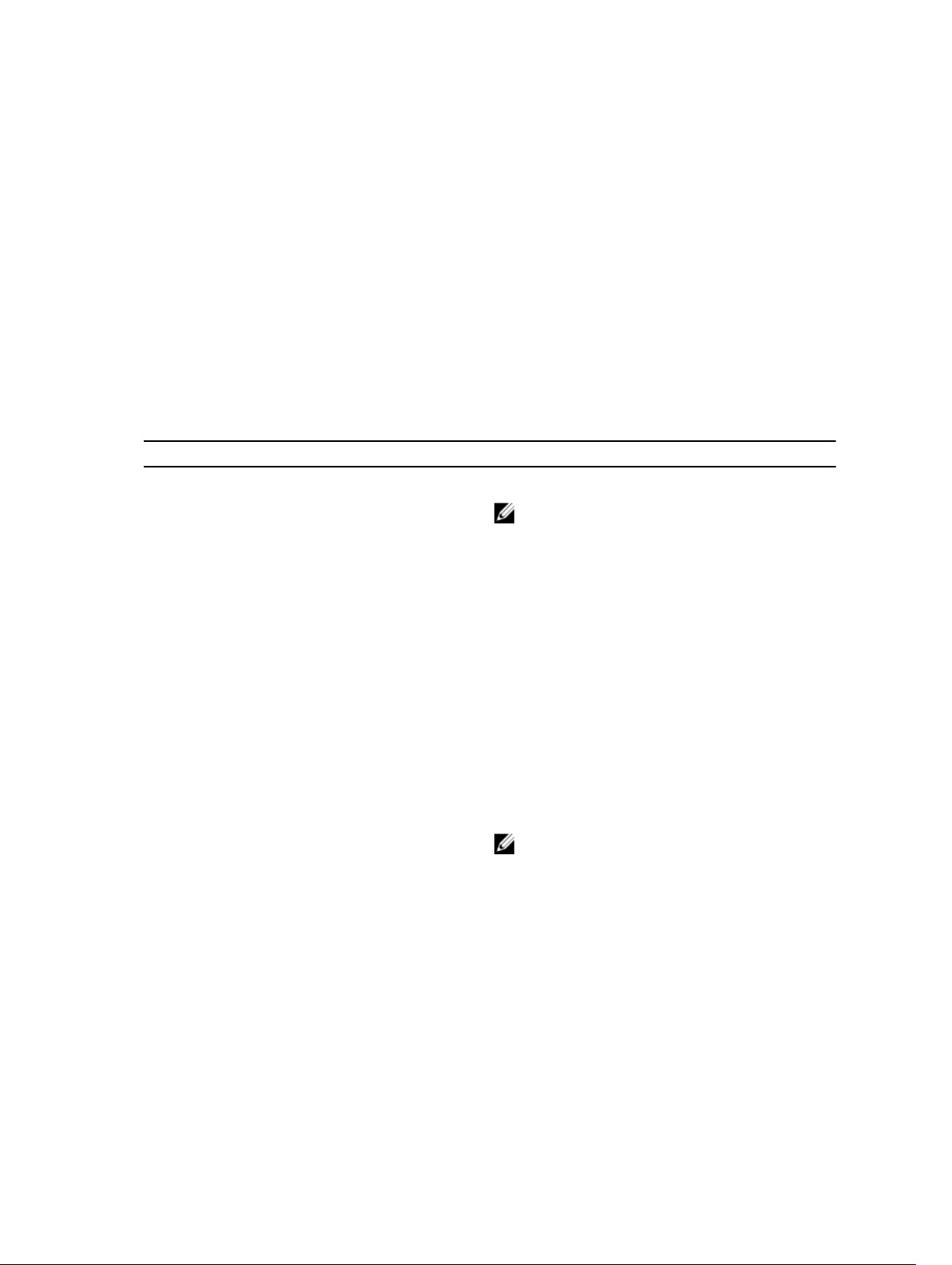
Figure 1. Front panel features and indicators
Item Indicator, Button, or Connector Description
1 Drive drawer Consists of up to sixteen 2.5 inch hard drives/SSDs.
2 Mini Enterprise Service Tag
(MEST)
3 Sled release latch (2) Used to slide the storage sled out of the enclosure.
4 Sled lock (2) Used to secure or release the storage sled from the
5 Storage sled status indicator Provides information on the overall status of the storage
6 Drive drawer release handle Used to slide the drive drawer out of the storage sled.
A removable label panel that lists the system Service Tag.
enclosure.
sled.
Storage sled status indicator
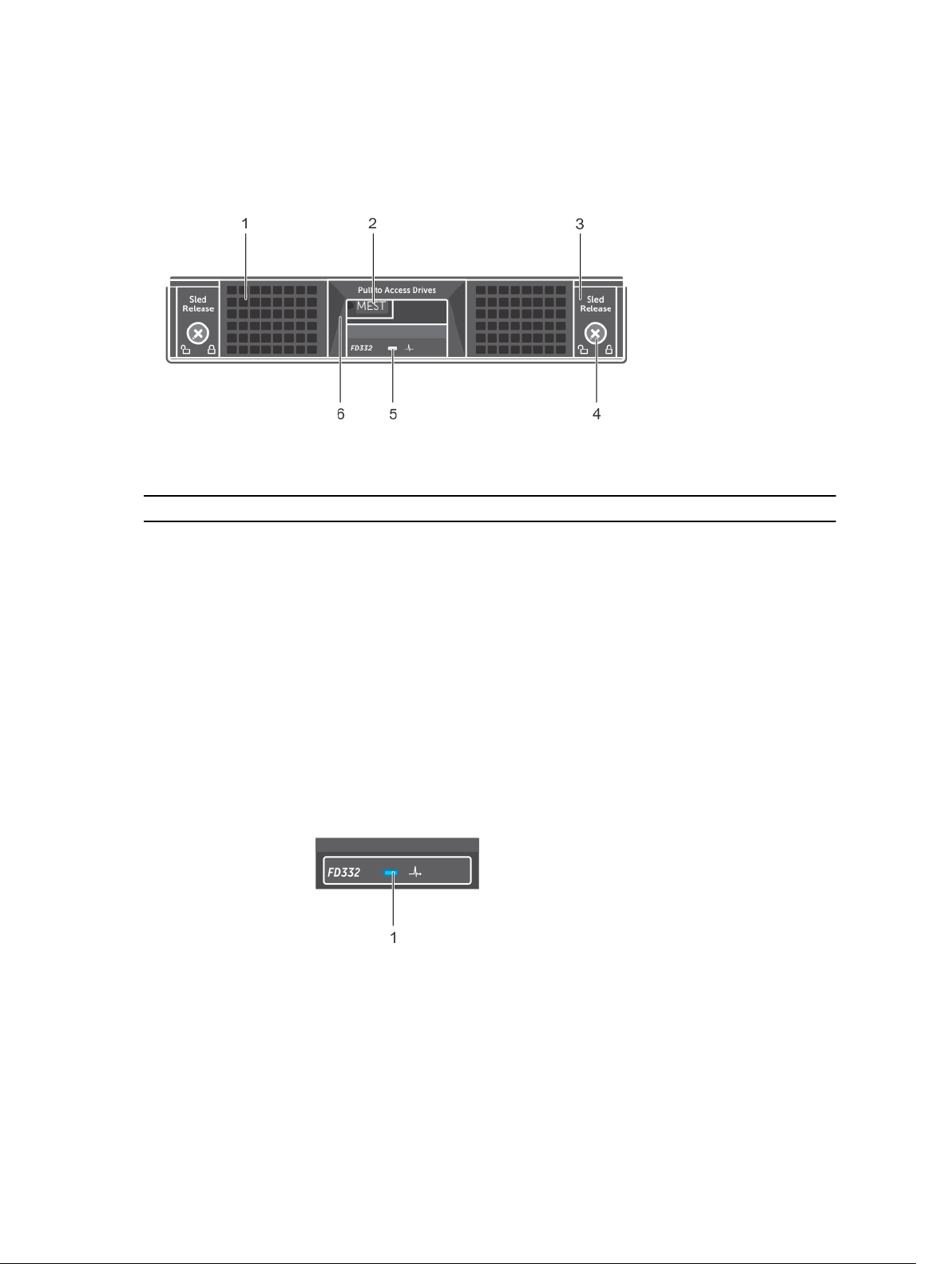
Figure 2. Storage sled status indicator
1. storage sled status indicator
The storage sled status indicator located on the sled front panel provides the following information on
the overall status of the sled.
6
Page 7
Indicator pattern Description
Solid blue The storage sled is powered on, and is operating
normally.
Blinking blue The compute sled to which the storage sled is
mapped, is identified.
Blinking amber The storage sled or any component inside the
storage sled is in fault condition.
Hard drive/SSD indicators
The hard drive/SSD indicators are located on top of the drive drawer. There is a single status/activity
indicator for each drive slot.
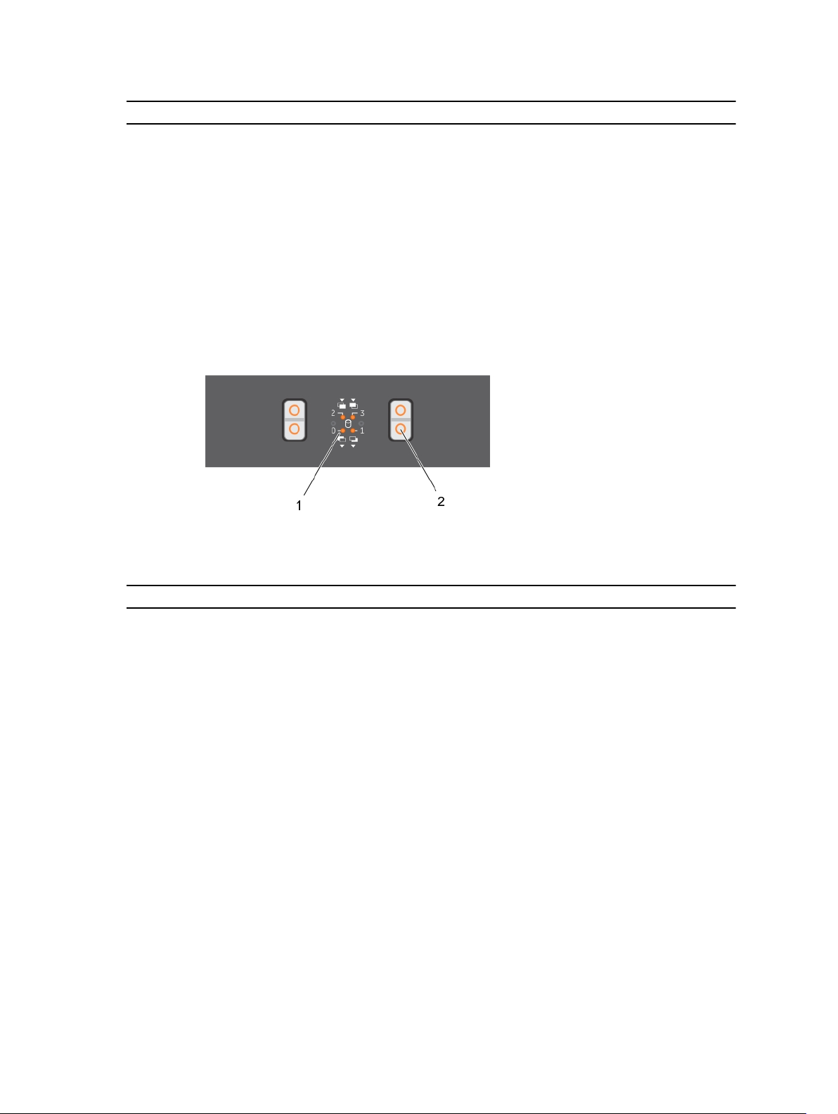
Figure 3. Hard drive/SSD indicators
1. hard drive/SSD indicator 2. hard drive/SSD release tab
Drive-Status Indicator Pattern Description
Off Drive slot empty
Steady green Drive online, but no activity
Blinks green and turns off Drive online with drive activity
Blinks green (On 250 ms Off 250 ms) Drive being identified or preparing for removal
Blinks green (On 400 ms Off 100 ms) Drive rebuilding
Blinks amber (On 150 ms Off 150 ms) Drive failed
Blinks green (500 ms), amber (500 ms), and turns
off one second
Blinks green three seconds, turns off three
seconds, blinks amber three seconds, and turns off
three seconds
Drive predicted failure
Drive rebuild aborted
Storage controller card indicators
The storage controller card indicators are located on top of the drive drawer.
7
Page 8
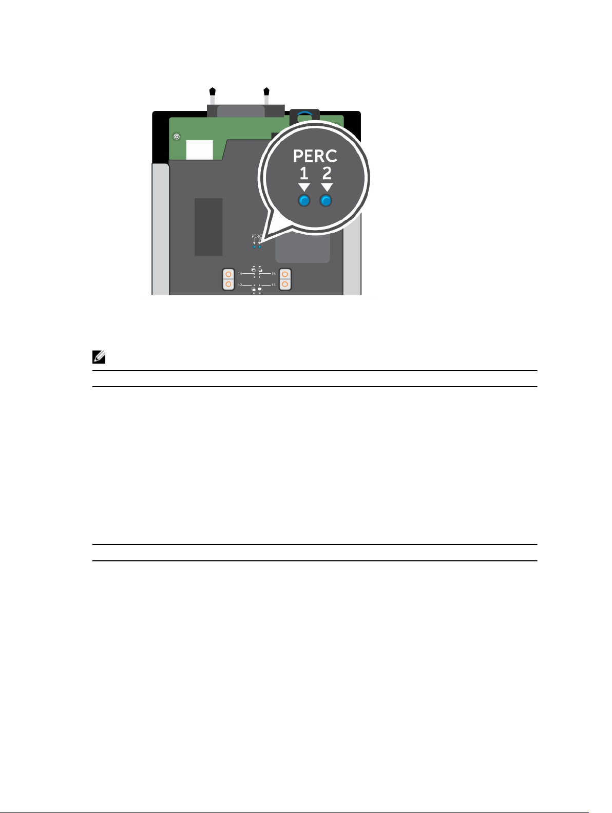
Figure 4. Storage controller card indicators
1. indicator for PERC 1 2. indicator for PERC 2
NOTE: The PERC 2 indicator is always Off if you are using a single PERC.
Indicator pattern Description
Off Storage controller card is offline
Solid blue Storage controller card is online
Blinks blue Storage controller or the compute sled to which it
is mapped is being identified
Blinks amber and turns off Storage controller card is in fault condition
Documentation matrix
The documentation matrix provides information about documents that you can refer to, for setting up
and managing your system.
To... Refer to...
Set up your system and know the system technical
specifications
Know the storage sled features, storage sled to
compute sled configuration options, remove and
install storage sled components, and troubleshoot
components
Get an overview of the Dell Systems Management
offerings
8
Getting Started With Your System
Owner’s Manual at dell.com/poweredgemanuals
Dell OpenManage Systems Management Overview
Guide at dell.com/openmanagemanuals
Page 9
To... Refer to...
Know about how to configure storage mode in the
storage sled and remote management of the
storage sled from the Chassis Management
Controller (CMC) interface
Know about remote management of the storage
sled from the integrated Dell Remote Access
Controller (iDRAC) interface
Know about the RACADM subcommands and
supported RACADM interfaces
Know the compute sled features, remove and
install compute sled components, and
troubleshoot components
Know the enclosure features, remove and install
enclosure components, and troubleshoot
enclosure components
Know the features of the storage controller cards,
deploy the cards, and manage the storage
subsystem
See the event and error messages generated by the
system firmware and agents that monitor system
components
PowerEdge FX2/FX2s CMC User’s Guide at
dell.com/esmmanuals
iDRAC User’s Guide at dell.com/esmmanuals
RACADM Command Line Reference Guide for
iDRAC and CMC at dell.com/esmmanuals
Compute sled Owner’s Manual at dell.com/
poweredgemanuals
Enclosure Owner’s Manual at dell.com/
poweredgemanuals
Storage controller documentation at dell.com/
storagecontrollermanuals
Dell Event and Error Messages Reference Guide at
dell.com/esmmanuals
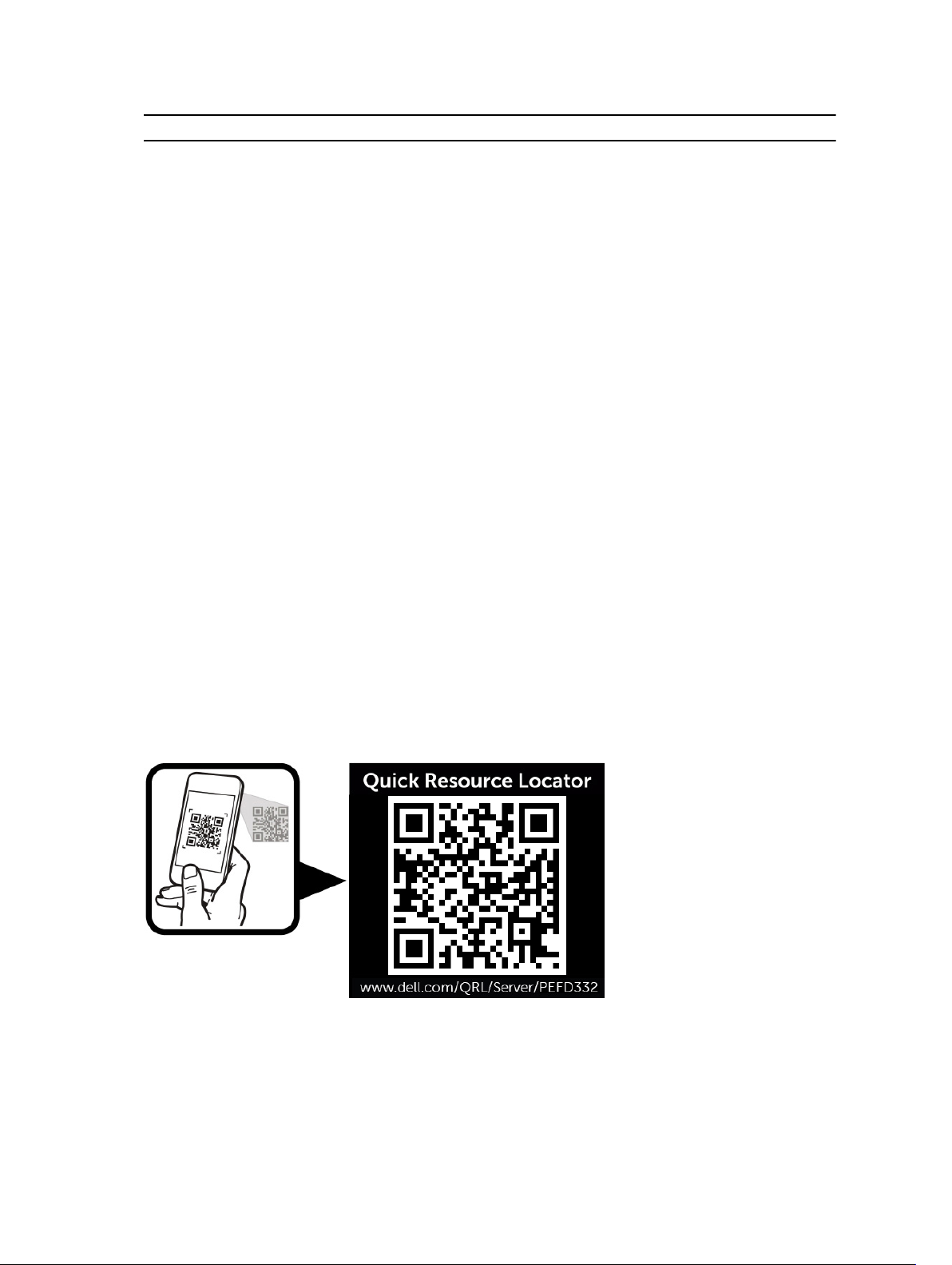
Quick Resource Locator
Use the Quick Resource Locator (QRL) to get immediate access to system information and how-to
videos. This can be done by visiting dell.com/QRL or by using your smartphone and a model specific
Quick Resource (QR) code located on your Dell PowerEdge system. To try out the QR code, scan the
following image.
9
Page 10
2
Performing initial system configuration
After you receive your PowerEdge FD332 system, you must set up your system in the enclosure. If your
storage sled has shipped pre-installed in the enclosure, it is recommended that you remove the sled
before you install the enclosure in the rack, to reduce chassis weight.
Setting up your PowerEdge FD332
1. Unpack the storage sled.
NOTE: If your storage sled has shipped pre-installed in the enclosure, remove the sled before
installing the enclosure in the rack, to reduce chassis weight. See Removing a storage sled.
NOTE: If you are installing the storage sled in an enclosure that is already powered on, you
need not turn off the enclosure to install the storage sled. Only the compute sled(s) to which
the storage sled is mapped must be turned off.
2. Turn off the compute sled(s) to which the storage sled is mapped, by using the CMC, iDRAC, or the
power button on the compute sled(s). For information on mapping configurations of storage sleds to
compute sleds, see Storage sled mapping configurations.
3. Remove the I/O connector cover from the storage sled connectors.
4. Install the storage sled in the enclosure. See Installing a storage sled.
NOTE: Install the storage sled(s) in the bottom slots of the PowerEdge FX2s enclosure,
beginning from the left (slot 3). In the four-bay chassis that supports up to three storage sleds,
you can also install a storage sled in the top right slot (slot 2) of the enclosure. For information
on sled slot numbering, see the Dell PowerEdge FX2 and FX2s Enclosure Owner's Manual at
dell.com/poweredgemanuals.
NOTE: You cannot install the storage sled in the top left slot (slot 1) of the four-bay chassis.
5. Turn on the compute sled(s) to which the storage sled is mapped, by using the iDRAC, CMC, or the
compute sled power button.
NOTE: The storage sled turns on when the compute sled(s) to which it is mapped is/are turned
on. For information on the mapping configurations, see Storage sled mapping configurations.
NOTE: If the enclosure is not powered on when you are installing the compute and storage
sleds, turn on the enclosure and wait for it to initialize before turning on the compute sled(s).
Managing your system remotely
You can manage and monitor the storage sled by using:
• the Chassis Management Controller (CMC). For more information, see the CMC User’s Guide at
dell.com/esmmanuals.
10
Page 11

• the iDRAC of the compute sled to which the storage sled is mapped. For more information, see the
iDRAC User’s Guide at dell.com/esmmanuals.
• the Dell OpenManage Server Administration (OMSA) software. For more information, see dell.com/
openmanagemanuals.
Downloading drivers and firmware
It is recommended that you download and install the latest BIOS, drivers, and systems management
firmware on the compute sled to which the storage sled is mapped, and on the chassis infrastructure.
Prerequisites
Ensure that you clear the web browser cache.
Steps
1. Go to dell.com/support/drivers.
2. In the Product Selection section, enter the Service Tag of your system in the Service Tag or Express
Service Code field.
NOTE: If you do not have the Service Tag, select Automatically detect my Service Tag for me
to allow the system to automatically detect your Service Tag, or select Choose from a list of all
Dell products to select your product from the Product Selection page.
3. Click Get drivers and downloads.
The drivers that are applicable to your selection are displayed.
4. Download the drivers you require to a diskette drive, USB drive, CD, or DVD.
11
Page 12
3
Storage sled mapping configurations
The storage controller(s) inside a storage sled map to compute sled(s) in the enclosure. PowerEdge FX2s
supports multiple storage sled to compute sled mapping configurations.
NOTE: Storage sled to compute sled mapping is pre-configured.
NOTE: The PowerEdge FM120x4 compute sled does not support the storage sled. You cannot map
a storage sled to the PowerEdge FM120x4 half-width compute sled.
For information on configuring the storage mode in the storage sleds, see the PowerEdge FX2/FX2s CMC
User’s Guide at dell.com/esmmanuals.
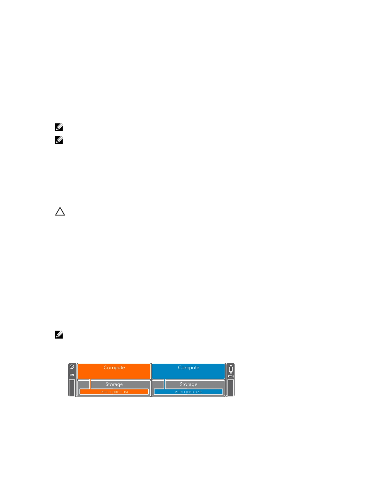
Single PERC and joined mode mapping configurations
CAUTION: Changing the storage sled mapping configuration from Split Single Host mode to
Joined mode can change some hard drives/SSDs to non-RAID mode.
The single PERC and joined mode configurations apply to the following:
• The storage sled supports a storage controller module with a single PERC, and all hard drives/SSDs
map to the single PERC.
• The storage sled supports a storage controller module with dual PERCs, but only the primary
controller is enabled by setting the Storage Mode to Joined in the Chassis Management Controller
(CMC) interface. All hard drives/SSDs in the storage sled map to the primary PERC in the joined mode.
The following enclosure configurations support single PERC and joined mode mapping.
• Four-bay chassis—controllers inside two storage sleds map to two half-width compute sleds
• Four-bay chassis (one compute sled)—controllers inside three storage sleds map to one half-width
compute sled
• Six-bay chassis—controllers inside two storage sleds map to two quarter-width compute sleds
• Three-bay chassis—controllers inside two storage sleds map to one full-width compute sled
NOTE: PowerEdge FX2s supports multiple single PERC and joined mode mapping configurations.
You must select the desired configuration based on your intended usage.
Figure 5. Single PERC/joined mode mapping configuration—four-bay chassis
12
Page 13
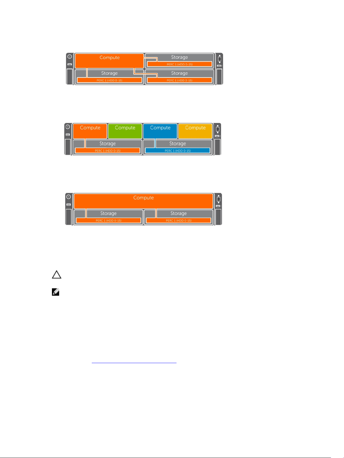
Figure 6. Single PERC/joined mode mapping configuration—four-bay chassis (one compute sled)
Figure 7. Single PERC/joined mode mapping configuration—six-bay chassis
Figure 8. Single PERC/joined mode mapping configuration—three-bay chassis
Split mode mapping configurations
CAUTION: Changing the storage sled mapping configuration from Joined mode to Split mode
can result in loss of configuration and/or loss of access to hard drives/SSDs.
NOTE: When changing the mapping configuration from Joined mode to Split mode, the secondary
PERC is powered on. It is recommended that you run the latest PERC firmware Dell Update Package
(DUP) to ensure that both PERCs are running the latest firmware.
The split mode mapping configurations apply to the following:
• The storage sled supports a storage controller module with dual PERCs.
• Both controllers are enabled by setting the Storage Mode to split mode in the CMC interface.
In the split mode, eight hard drives/SSDs are assigned map to each PERC. Hard drives/SSDs in slots 0 to 7
map to PERC 1 or primary controller, and hard drives/SSDs in slots 8 to 15 map to PERC 2. For more
information, see Drive to storage controller mapping.
There are two split mode options available in the CMC interface:
• Split Single Host mode
13
Page 14
• Split Dual Host mode
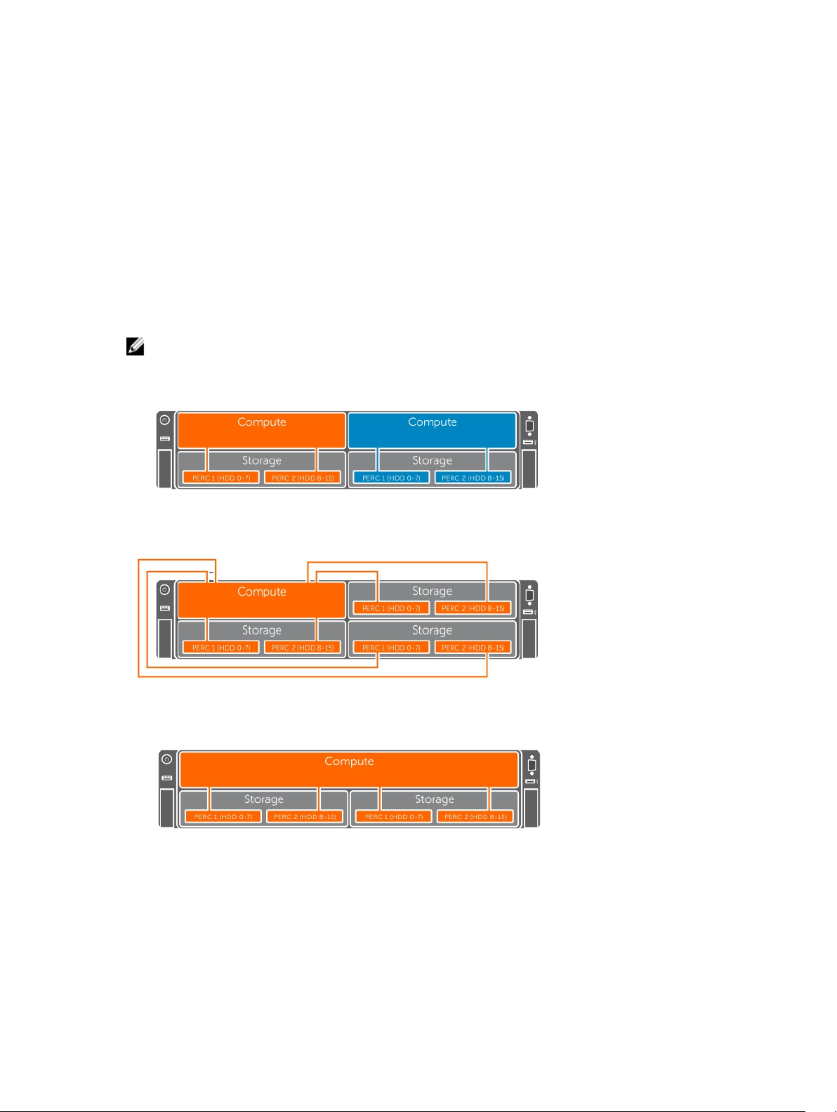
Split single host mapping configuration
In the split single host mapping configuration, dual controllers inside a storage sled map to a single
compute sled.
The following enclosure configurations support split single host mapping.
• Four-bay chassis with two compute sleds—dual controllers inside a storage sled map to a half-width
compute sled.
• Four-bay chassis with one compute sled—dual controllers inside each storage sled map to the single
half-width compute sled.
• Three-bay chassis with one compute sled—dual controllers inside each storage sled map to the single
full-width compute sled.
NOTE: PowerEdge FX2s supports multiple split single host mapping configurations. You must select
the desired configuration based on your intended usage.
Figure 9. Split single host mapping configuration—four-bay chassis
Figure 10. Split single host mapping configuration—four-bay chassis (one compute sled)
Figure 11. Split single host mapping configuration—three-bay chassis
Split dual host mapping configuration
In the split dual host mapping configuration, dual controllers inside one storage sled are mapped to two
different compute sleds.
14
Page 15
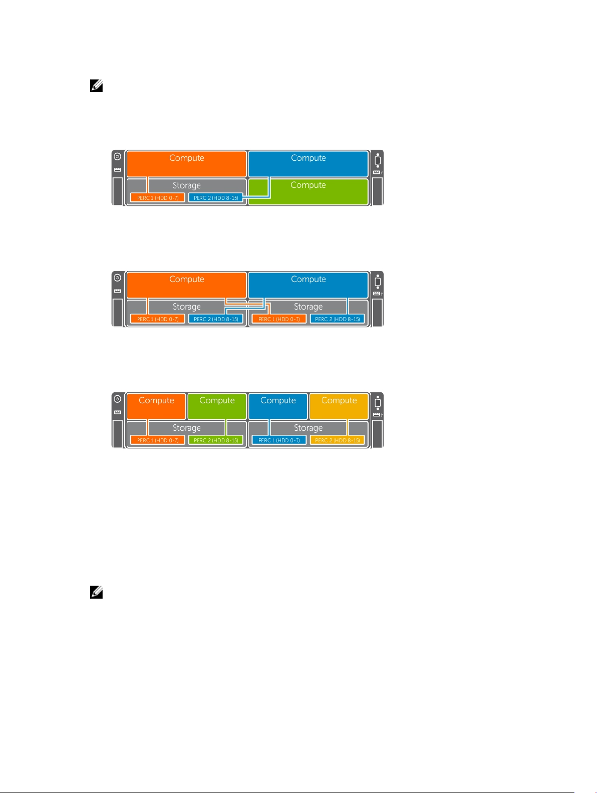
NOTE: PowerEdge FX2s supports multiple split dual host mapping configurations. You must select
the desired configuration based on your intended usage.
The following are examples of split dual host mapping configurations.
Figure 12. Split dual host configuration—four-bay chassis
Figure 13. Split dual host configuration—four-bay chassis
Figure 14. Split dual host configuration—six-bay chassis
Drive to storage controller mapping
Your system supports up to sixteen 2.5 inch SAS/SATA hard drives/SSDs.
When you install a storage controller module with a single PERC, all the drives map to the single PERC.
When you install a storage controller module with dual PERCs, the drives in slots 0 to 7 map to PERC 1 or
the primary controller. The drives in slots 8 to 15 map to PERC 2 or the secondary controller.
NOTE: In the split single host storage mode, the storage controller enumeration in the PERC BIOS
Configuration (Ctrl+R) utility is different from the enumeration in the iDRAC and Human Interface
Infrastructure (HII) interfaces. In the Ctrl+R utility, the secondary controller is listed before the
primary controller. It is recommended that you review the Ctrl+R slot information detail to
determine the appropriate controller. For example, Slot 0x31, where 3 refers to the storage sled slot
number and 1 refers to the controller 1. Similarly, in Slot 0x32, 3 refers to the storage sled slot
number and 2 refers to controller 2.
15
Page 16

Figure 15. Mapping of drives to dual storage controllers
Icon Description
Hard drives/SSDs mapped to the primary controller or PERC 1.
Hard drives/SSDs mapped to the secondary controller or PERC 2.
16
Page 17

4
Installing and removing storage sled components
This section provides information on installing and removing the storage sled components. For
information on removing and installing the compute sled components, see the relevant sled Owner’s
Manual at dell.com/poweredgemanuals. For information on installing and removing the enclosure
components, see the enclosure Owner's Manual at dell.com/poweredgemanuals.
Customer and field replaceable units—PowerEdge FD332
The following components are customer replaceable units (CRUs):
• hard drive/SSD assembly
• storage controller module batteries
NOTE: For information on removing and installing the storage controller module batteries, see
the Dell PowerEdge RAID Controller (PERC) 9 User’s Guide at dell.com/
storagecontrollermanuals.
The following components are field replaceable units (FRUs). Removal and installation procedures of the
FRUs should be performed only by Dell certified service technicians.
• Hard drives/SSDs from drive rails
• Mini Enterprise Service Tag (MEST)
• Storage controller module
• Bezel assembly
Safety instructions
CAUTION: Many repairs may only be done by a certified service technician. You should only
perform troubleshooting and simple repairs as authorized in your product documentation, or as
directed by the online or telephone service and support team. Damage due to servicing that is
not authorized by Dell is not covered by your warranty. Read and follow the safety instructions
that came with the product.
NOTE: It is recommended that you always use an antistatic mat and antistatic strap while working
on components inside the system.
Before working inside your system
1. Turn off the compute sled(s) to which the storage sled is mapped, by using the CMC, iDRAC, or the
power button on the compute sled.
When the sled is turned off, its front panel power indicator is off.
17
Page 18

The storage sled also turns off.
2. Remove the storage sled from the enclosure.
3. Install the I/O connector cover.
Related Links
Removing a storage sled
After working inside your system
1. Remove the I/O connector cover.
2. Install the storage sled in the enclosure.
3. Turn on the compute sled(s) to which the storage sled is mapped.
The storage sled turns on after the compute sled is turned on.
Related Links
Installing a storage sled
Recommended tools
You may need the following items to perform the procedures in this section:
• #1 and #2 Phillips screwdrivers
• T15 Torx driver
Storage sled
Removing a storage sled
Prerequisites
CAUTION: Many repairs may only be done by a certified service technician. You should only
perform troubleshooting and simple repairs as authorized in your product documentation, or as
directed by the online or telephone service and support team. Damage due to servicing that is
not authorized by Dell is not covered by your warranty. Read and follow the safety instructions
that came with the product.
CAUTION: Removing the storage sled from the enclosure when the storage sled is powered on
results in loss of data.
CAUTION: To prevent damage to the storage sled locks, use a #2 Phillips screwdriver to turn the
sled locks to lock or unlock positions.
1. Ensure that you read the Safety instructions provided in this document.
2. Turn off the compute sled(s) to which the storage sled is mapped, by using the CMC, iDRAC, or the
sled power button.
3. Keep the #2 Phillips screwdriver ready.
Steps
1. Using a Phillips #2 screwdriver, turn the storage sled locks on the sled front panel to unlock position.
18
Page 19

CAUTION: If you are permanently removing the sled, install a sled blank. Operating the
enclosure for extended periods of time without a sled blank installed can cause the enclosure
to overheat.
2. Lift the sled release latches upward by 90 degrees, and holding it by the latches, pull the sled out of
the enclosure.
CAUTION: To protect the I/O connector pins, install the I/O connector cover every time a
sled is removed from the enclosure.
3. Install the I/O connector cover over the I/O connectors.
Figure 16. Removing a storage sled
1. sled lock (2) 2. dotted line on storage sled
3. sled release latch (2)
19
Page 20

Figure 17. Removing and installing the I/O connector cover
1. storage sled 2. I/O connector cover
Next steps
Install the storage sled or sled blank.
Related Links
Safety instructions
Storage sled mapping configurations
Installing a storage sled
Prerequisites
CAUTION: Many repairs may only be done by a certified service technician. You should only
perform troubleshooting and simple repairs as authorized in your product documentation, or as
directed by the online or telephone service and support team. Damage due to servicing that is
not authorized by Dell is not covered by your warranty. Read and follow the safety instructions
that came with the product.
CAUTION: To prevent damage to the I/O connectors, do not touch the connectors or the
connector pins.
CAUTION: To prevent damage to the sled locks, use a #2 Phillips screwdriver to turn the sled
locks to lock or unlock positions.
NOTE: Install the storage sleds in the bottom slots of the PowerEdge FX2s enclosure, beginning
from the left (slot 3). In the four-bay chassis, you can also install a storage sled in the top right slot
(slot 2) of the enclosure. For more information on sled slot numbering, see the
and FX2s Enclosure Owner's Manual at dell.com/poweredgemanuals.
NOTE: If your storage sled has shipped pre-installed in the enclosure, it is recommended that you
remove the sled before installing the enclosure in the rack, to reduce chassis weight.
NOTE: If you are installing the storage sled in an enclosure that is already powered on, you need not
turn off the enclosure to install the storage sled. Only the compute sled(s) to which the storage sled
is mapped must be turned off.
Dell PowerEdge FX2
1. Ensure that you read the Safety instructions.
2. Turn off the compute sled to which the storage sled is mapped, by using the CMC, iDRAC, or the
power button on the compute sled.
20
Page 21

3. Keep the #2 Phillips screwdriver ready.
Steps
1. If you are installing a new storage sled, remove the I/O connector cover and save for future use.
2. Align the storage sled with the bay in the enclosure.
CAUTION: To ensure that a storage sled is properly installed, slide the sled into the enclosure
bay until the dotted line on top of the storage sled is not visible from the top edge of the bay
in which the storage sled is being installed.
CAUTION: If a compute sled is already installed in an enclosure bay above the bay in which
you are installing a storage sled, the compute sled may obscure the dotted line on the
storage sled. Do not use the compute sled installed in the top enclosure bay as a point of
reference for visibility of the dotted line on top of the storage sled. For the storage sled to be
properly installed, ensure that the dotted line on the storage sled is not visible from the top
edge of the bay in which the storage sled is installed.
3. Slide the storage sled into the enclosure until the dotted line on top of the sled is not visible from the
top edge of the bay, and the sled clicks into place.
4. Turn the storage sled locks to the lock position, to secure the sled in the enclosure.
CAUTION: Ensure that the sled locks are in locked position before opening the storage sled
drive drawer, as the storage sled must be locked in the enclosure before you open the drive
drawer.
21
Page 22

Figure 18. Installing a storage sled
1. dotted line on storage sled 2. sled lock (2)
Next steps
Turn on the compute sled(s) to which the storage sled is mapped. The storage sled turns on.
Related Links
Safety instructions
Storage sled mapping configurations
22
Page 23

Inside the sled
Figure 19. Inside the sled
1. storage controller module 2. I/O connector to enclosure midplane
3. storage controller module cable 4. drive drawer
5. hard-drive/SSD release tab (16) 6. dotted line on top of storage sled
Drive drawer
The drive drawer supports up to 16 hot swap hard drives/SSDs. You must open the drive drawer and
access the drives from the sides of the drawer.
23
Page 24

Opening the drive drawer
Prerequisites
CAUTION: Many repairs may only be done by a certified service technician. You should only
perform troubleshooting and simple repairs as authorized in your product documentation, or as
directed by the online or telephone service and support team. Damage due to servicing that is
not authorized by Dell is not covered by your warranty. Read and follow the safety instructions
that came with the product.
CAUTION: The storage sled must be locked in the enclosure before you open the drive drawer.
Ensure that the sled locks are in locked position.
CAUTION: Do not keep the drive drawer open for more than three minutes.
Ensure that you read the Safety instructions.
Steps
Pull the drive drawer handle on the front panel of the storage sled, and slide the drawer out of the
sled until you access the hard drives/SSDs.
Figure 20. Opening the drive drawer
1. sled lock 2. drive drawer
3. drive drawer handle
24
Page 25

Figure 21. Service caution label on the drive drawer
Next steps
Close the drive drawer.
Related Links
Closing the drive drawer
Closing the drive drawer
Prerequisites
CAUTION: Many repairs may only be done by a certified service technician. You should only
perform troubleshooting and simple repairs as authorized in your product documentation, or as
directed by the online or telephone service and support team. Damage due to servicing that is
not authorized by Dell is not covered by your warranty. Read and follow the safety instructions
that came with the product.
CAUTION: Ensure that the sled locks are in the locked position.
CAUTION: Ensure that the drive drawer handle is in closed position before closing the drawer.
NOTE: You must open the drive drawer to install hard drives/SSDs or service hard drives/SSDs in the
drawer.
1. Ensure that you read the Safety instructions.
2. Open the drive drawer.
Steps
Slide the drive drawer into the sled until it is fully seated.
25
Page 26

Figure 22. Closing the drive drawer
1. sled lock (2) 2. drive drawer
3. dotted line on the drive drawer
Related Links
Opening the drive drawer
Mini Enterprise Service Tag
The Mini Enterprise Service Tag is a removable label panel located on the storage sled front panel, which
lists the system Service Tag.
Removing the Mini Enterprise Service Tag
Prerequisites
CAUTION: Many repairs may only be done by a certified service technician. You should only
perform troubleshooting and simple repairs as authorized in your product documentation, or as
directed by the online or telephone service and support team. Damage due to servicing that is
not authorized by Dell is not covered by your warranty. Read and follow the safety instructions
that came with the product.
NOTE: This is a field replaceable unit (FRU). Removal and installation procedures must be performed
only by Dell certified service technicians.
26
Page 27

1. Ensure that you read the Safety instructions.
2. Keep the #1 Phillips screwdriver ready.
Steps
1. Pull the drive drawer handle on the front panel of the storage sled, and keep it in open position.
2. Remove the screw securing the Mini Enterprise Service Tag (MEST) to the sled front panel.
3. Remove the MEST from the sled.
Figure 23. Removing and installing the MEST
1. screw 2. MEST
Next steps
Install the MEST.
Related Links
Installing the Mini Enterprise Service Tag
Installing the Mini Enterprise Service Tag
Prerequisites
CAUTION: Many repairs may only be done by a certified service technician. You should only
perform troubleshooting and simple repairs as authorized in your product documentation, or as
directed by the online or telephone service and support team. Damage due to servicing that is
not authorized by Dell is not covered by your warranty. Read and follow the safety instructions
that came with the product.
NOTE: This is a field replaceable unit (FRU). Removal and installation procedures must be performed
only by Dell certified service technicians.
1. Ensure that you read the Safety instructions.
2. Keep the #1 Phillips screwdriver ready.
3. Remove the Mini Enterprise Service Tag (MEST).
27
Page 28

Steps
1. Align the edge of the MEST opposite to the screw hole end, with the slot on the sled front panel.
2. Align the screw hole on the tag with the screw hole on the sled front panel and install the screw to
secure the tag to the sled front panel.
3. Close the drive drawer handle.
Related Links
Removing the Mini Enterprise Service Tag
Hard drive/SSD assembly
Your storage sled supports up to sixteen 2.5 inch SAS/SATA hard drives/SSDs.
The hard drive assembly consists of the following:
• Hard drive/SSD
• Hot swap drive rails that fit in the drive slots, and into which the drive is installed
• Screws securing the drive to the drive rails
Removing a hard drive/SSD assembly
Prerequisites
CAUTION: Many repairs may only be done by a certified service technician. You should only
perform troubleshooting and simple repairs as authorized in your product documentation, or as
directed by the online or telephone service and support team. Damage due to servicing that is
not authorized by Dell is not covered by your warranty. Read and follow the safety instructions
that came with the product.
CAUTION: To prevent data loss, ensure that your operating system supports hot-swap drive
installation. See the documentation supplied with your operating system.
CAUTION: Do not keep the drive drawer open for more than three minutes.
1. Ensure that you read the Safety instructions.
2. Using the management software like OpenManage Server Administrator (OMSA), prepare the hard
drive/SSD for removal.
If the hard drive/SSD is online, the drive indicator flashes as the drive is turned off. You can remove
the hard drive/SSD when the drive indicator turns off.
3. Open the drive drawer.
Steps
1. Press the release tab of the hard drive/SSD that you want to remove.
The drive rail release handle slides out of the drive slot.
NOTE: The hard drive/SSD release tabs are located on top of the drive drawer. The drive slot
number near each release tab indicates the release tab for the drive in the slot.
CAUTION: Exercise caution when you pull out the hard drive/SSD assembly, because excess
force can cause the drive assembly to fall. It is recommended that you support the bottom of
the drive assembly with one hand while holding the drive release handle with the other hand.
2. Holding the drive rail release handle, pull the hard drive/SSD assembly out of the drive slot.
28
Page 29

Figure 24. Removing and installing a hard drive/SSD assembly
1. hard drive/SSD release tab 2. drive rail release handle
29
Page 30

Figure 25. Release tabs for the top and bottom hard drives/SSDs
Next steps
Install the hard drive/SSD assembly.
Related Links
Installing a hard drive/SSD assembly
Opening the drive drawer
Installing a hard drive/SSD assembly
Prerequisites
CAUTION: Many repairs may only be done by a certified service technician. You should only
perform troubleshooting and simple repairs as authorized in your product documentation, or as
directed by the online or telephone service and support team. Damage due to servicing that is
not authorized by Dell is not covered by your warranty. Read and follow the safety instructions
that came with the product.
CAUTION: Use only hard drives/SSDs that have been tested and approved for use with the hard
drive backplane.
CAUTION: Combining SAS and SATA hard drives/SSDs in the same RAID volume is not supported.
30
Page 31

CAUTION: When installing a hard drive/SSD, ensure that the adjacent drives are fully installed.
Inserting a drive assembly and attempting to lock its handle next to a partially installed assembly
can damage the shield spring of the partially installed assembly, and make it unusable.
CAUTION: To prevent data loss, ensure that your operating system supports hot-swap drive
installation. See the documentation supplied with your operating system.
CAUTION: Do not keep the drive drawer open for more than three minutes.
CAUTION: When a replacement hot-swappable hard drive is installed and the system is powered
on, the hard drive automatically begins to rebuild. Make absolutely sure that the replacement
hard drive is blank or contains data that you wish to have over-written. Any data on the
replacement hard drive is immediately lost after the hard drive is installed.
NOTE: If the replacement hard drive/SSD is an online drive that is migrated from another system, it
is detected as Foreign in the PERC BIOS Configuration utility. You can import the existing
configuration or clear the data from the drive. For more information on foreign configuration, see
the Dell PowerEdge RAID Controller (PERC) 9 User’s Guide at dell.com/storagecontrollermanuals.
1. Ensure that you read the Safety instructions.
2. Open the drive drawer.
Steps
1. Align the drive rails with the standoffs in the drive slot, with:
a. the connector side of the hard drive/SSD facing up, for even-numbered drive slots.
b. the connector side of the hard drive/SSD facing down, for odd-numbered drive slots.
31
Page 32

Figure 26. Hard drive/SSD assembly orientation for even and odd-numbered slots
1. hard drive/SSD assembly orientation for
2. storage sled
even numbered slots (with connector side
of drive facing up)
3. hard drive/SSD assembly orientation for
odd numbered slots (with connector side
of drive facing down)
2. Slide the drive assembly into the slot until the drive connector engages with the connector on the
backplane.
3. Close the drive release handle until it clicks into place, to lock the hard drive/SSD.
Next steps
Close the drive drawer.
Related Links
Removing a hard drive/SSD assembly
Opening the drive drawer
Closing the drive drawer
32
Page 33

Removing a hard drive/SSD from the drive rails
Prerequisites
CAUTION: Many repairs may only be done by a certified service technician. You should only
perform troubleshooting and simple repairs as authorized in your product documentation, or as
directed by the online or telephone service and support team. Damage due to servicing that is
not authorized by Dell is not covered by your warranty. Read and follow the safety instructions
that came with the product.
CAUTION: Do not keep the drive drawer open for more than three minutes.
NOTE: This is a field replaceable unit (FRU). Removal and installation procedures must be performed
only by Dell certified service technicians.
NOTE: You must remove a hard drive/SSD from the drive rails if you are replacing the hard
drive/SSD with a new drive.
NOTE: The drive rails are attached to the sides of the hard drive/SSD. One of the rails comprises the
release handle.
1. Ensure that you read the Safety instructions.
2. Open the drive drawer.
3. Remove the hard drive/SSD assembly from the drive drawer.
4. Close the drive drawer.
5. Keep the #1 Phillips screwdriver ready.
Steps
Remove the screws securing the hard drive/SSD to the drive rails.
Figure 27. Removing and installing a hard drive/SSD into the drive rails
1. drive rail 2. hard drive/SSD
33
Page 34

3. drive rail with release handle 4. screw (4)
Next steps
Install the hard drive/SSD into the drive rails.
Related Links
Installing a hard drive/SSD into the drive rails
Opening the drive drawer
Closing the drive drawer
Removing a hard drive/SSD assembly
Installing a hard drive/SSD into the drive rails
Prerequisites
CAUTION: Many repairs may only be done by a certified service technician. You should only
perform troubleshooting and simple repairs as authorized in your product documentation, or as
directed by the online or telephone service and support team. Damage due to servicing that is
not authorized by Dell is not covered by your warranty. Read and follow the safety instructions
that came with the product.
CAUTION: Do not keep the drive drawer open for more than three minutes.
NOTE: This is a field replaceable unit (FRU). Removal and installation procedures must be performed
only by Dell certified service technicians.
NOTE: You must remove a hard drive/SSD from the drive rails if you are replacing the hard
drive/SSD with a new drive.
1. Ensure that you read the Safety instructions.
2. Keep the #1 Phillips screwdriver ready.
3. Remove the hard drive/SSD from the drive rails.
Steps
1. Lay the hard drive/SSD on a flat surface with the connector side of the drive facing down.
2. Align the screw holes on the drive rails with the screw holes on the hard drive/SSD.
When aligned correctly, the drive rails are flush with the surface of the hard drive/SSD.
3. Install the screws to secure the drive to the drive rails.
Next steps
1. Open the drive drawer.
2. Install the drive assembly in the drive drawer.
3. Close the drive drawer.
Related Links
Removing a hard drive/SSD from the drive rails
Installing a hard drive/SSD assembly
Opening the drive drawer
Closing the drive drawer
Storage controller module
You system supports one storage controller module (SCM), which is available in two options:
34
Page 35

• FD33xS—storage controller module with single PERC
• FD33xD—storage controller module with dual PERC
NOTE: The default mode for the storage controller module is HBA mode. To enable RAID mode for
the SCM, you must upgrade to RAID mode licensing. For more information on RAID mode licensing,
see the PowerEdge FX2s CMC User’s Guide at dell.com/esmmanuals. For information on how to
import RAID mode license, see the Dell PowerEdge FX2/FX2s CMC Online Help.
For more information on the storage controller modules, and removing and installing the SCM
components, see the Dell PowerEdge RAID Controller (PERC) 9 User’s Guide at dell.com/
storagecontrollermanuals.
Removing the storage controller module
Prerequisites
CAUTION: Many repairs may only be done by a certified service technician. You should only
perform troubleshooting and simple repairs as authorized in your product documentation, or as
directed by the online or telephone service and support team. Damage due to servicing that is
not authorized by Dell is not covered by your warranty. Read and follow the safety instructions
that came with the product.
NOTE: This is a field replaceable unit (FRU). Removal and installation procedures must be performed
only by Dell certified service technicians.
NOTE: You must remove the storage controller module (SCM) to replace a faulty module.
1. Ensure that you read the Safety instructions.
2. Follow the procedure listed in Before working inside your system.
3. Keep the T15 Torx screwdriver ready for the storage controller module cable screws.
4. Keep the #2 Phillips screwdriver ready for the screws securing the storage controller module to the
module holder.
Steps
1. Open the drive drawer until the storage controller module is accessible.
2. Loosen the screws securing the module cable to the SCM.
3. Lift the module cable away from the SCM by holding the cable touch point.
4. Holding the touch point, allow the module cable to slowly retract into the cable coil.
5. Remove the screws securing the SCM to the module holder on the midplane interface module.
6. Holding the SCM by the touch points, lift the SCM from the connector on the midplane interface
module.
35
Page 36

Figure 28. Removing and installing the storage controller module
1. storage controller module 2. screw (3)
3. SCM cable touch point 4. SCM cable screw (2)
5. touch point on the SCM (4) 6. connector on midplane interface
Next steps
Install the storage controller module.
Related Links
Installing the storage controller module
Opening the drive drawer
Closing the drive drawer
Installing the storage controller module
Opening the drive drawer
module
Installing the storage controller module
Prerequisites
CAUTION: Many repairs may only be done by a certified service technician. You should only
perform troubleshooting and simple repairs as authorized in your product documentation, or as
directed by the online or telephone service and support team. Damage due to servicing that is
not authorized by Dell is not covered by your warranty. Read and follow the safety instructions
that came with the product.
36
Page 37

NOTE: This is a field replaceable unit (FRU). Removal and installation procedures must be performed
only by Dell certified service technicians.
1. Ensure that you read the Safety instructions.
2. Follow the procedure listed in Before working inside your system.
3. Keep the T15 Torx screwdriver ready for the storage controller module (SCM) cable screws.
4. Keep the #2 Phillips screwdriver ready for the screws securing the SCM to the module holder.
5. Remove the storage controller module.
Steps
1. Align the SCM with the connector on the midplane interface module.
2. Lower the SCM until it is firmly seated on the connector on the midplane interface module.
3. Install the screws to secure the SCM to the module holder on the midplane interface module.
4. Holding the module cable touch point, align the cable guide pins with the holes on the SCM.
5. Tighten the screws to secure the SCM cable to the module.
Next steps
1. Close the drive drawer.
2. Follow the procedure listed in After working inside your system.
NOTE: The replacement storage controller module is set to HBA mode by default. After
replacing a RAID mode licensed storage controller module, you must set the replacement
module to RAID mode.
3. Set the replacement storage controller module to RAID mode by using the PERC BIOS Configuration
Utility (Ctrl+R) or the Human Interface Infrastructure (HII) utility.
Related Links
Removing the storage controller module
Opening the drive drawer
Closing the drive drawer
Removing the storage controller module
Closing the drive drawer
Bezel assembly
The bezel assembly on the storage sled front panel comprises the drive drawer handle and the Mini
Enterprise Service Tag.
Removing the bezel assembly
Prerequisites
CAUTION: Many repairs may only be done by a certified service technician. You should only
perform troubleshooting and simple repairs as authorized in your product documentation, or as
directed by the online or telephone service and support team. Damage due to servicing that is
not authorized by Dell is not covered by your warranty. Read and follow the safety instructions
that came with the product.
CAUTION: To prevent damage to the storage sled locks, use a #2 Phillips screwdriver to turn the
sled locks to lock or unlock positions.
37
Page 38

NOTE: This is a field replaceable unit (FRU). Removal and installation procedures must be performed
only by Dell certified service technicians.
NOTE: You must remove the bezel assembly to replace a faulty bezel assembly or when you are
replacing the chassis.
1. Ensure that you read the Safety instructions.
2. Follow the procedure listed in Before working inside your system.
3. Remove the Mini Enterprise Service Tag (MEST) and save for future use.
4. Keep tweezers ready for the service caution label.
5. Keep the #2 Phillips screwdriver ready.
Steps
1. Release the service caution label from top of the storage sled by using tweezers.
2. Remove the service caution label and save for future use.
Figure 29. Removing and installing the service caution label
1. service caution label 2. storage sled
3. Using a Phillips #2 screwdriver, turn the sled locks to lock position.
4. Pull the drive drawer handle and open the drive drawer.
5. Remove the screws securing the bezel assembly to the top of the sled.
6. Turn the sled over with the bottom side of the sled facing up.
7. Remove the screws securing the bezel assembly to the bottom side of the sled.
8. Pull the bezel assembly out of the sled.
38
Page 39

Figure 30. Removing and installing the bezel assembly
1. screw (7) 2. top side of the sled
3. bezel assembly
Next steps
Install the bezel assembly.
Related Links
Installing the bezel assembly
Removing the Mini Enterprise Service Tag
Installing the bezel assembly
Prerequisites
CAUTION: Many repairs may only be done by a certified service technician. You should only
perform troubleshooting and simple repairs as authorized in your product documentation, or as
directed by the online or telephone service and support team. Damage due to servicing that is
not authorized by Dell is not covered by your warranty. Read and follow the safety instructions
that came with the product.
CAUTION: To prevent damage to the storage sled locks, use a #2 Phillips screwdriver to turn the
sled locks to lock or unlock positions.
39
Page 40

NOTE: This is a field replaceable unit (FRU). Removal and installation procedures must be performed
only by Dell certified service technicians.
1. Ensure that you read the Safety instructions.
2. Follow the procedure listed in Before working inside your system.
3. Keep the #2 Phillips screwdriver ready.
4. Remove the bezel assembly.
Steps
1. Turn the sled over with the bottom side of the sled facing up.
2. Align the bezel assembly with the sled front panel and push the assembly into the sled until it is fully
seated.
3. Install the screws securing the bezel assembly to the bottom side of the sled.
4. Turn the sled over with the top side of the sled facing up.
5. Install the screws securing the bezel assembly to the top of the sled.
6. Close the drive drawer.
7. Using a #2 Phillips screwdriver, turn the sled locks to unlock position.
8. Align the service caution label and paste the label on top of the drive drawer.
Next steps
1. Install the Mini Enterprise Service Tag (MEST).
2. Follow the procedure listed in After working inside your system.
Related Links
Removing the bezel assembly
Installing the Mini Enterprise Service Tag
40
Page 41

Troubleshooting your system
Safety first—for you and your system
CAUTION: Many repairs may only be done by a certified service technician. You should only
perform troubleshooting and simple repairs as authorized in your product documentation, or as
directed by the online or telephone service and support team. Damage due to servicing that is
not authorized by Dell is not covered by your warranty. Read and follow the safety instructions
that came with the product.
NOTE: For troubleshooting information on the PowerEdge FX2s enclosure components, see the
Dell PowerEdge FX2 and FX2s Enclosure Owner's Manual at dell.com/poweredgemanuals. For
information on troubleshooting the compute sled components, see the relevant compute sled
Owner’s Manual at dell.com/poweredgemanuals.
Troubleshooting hard drives/SSDs
Prerequisites
CAUTION: Many repairs may only be done by a certified service technician. You should only
perform troubleshooting and simple repairs as authorized in your product documentation, or as
directed by the online or telephone service and support team. Damage due to servicing that is
not authorized by Dell is not covered by your warranty. Read and follow the safety instructions
that came with the product.
CAUTION: This procedure can destroy data stored on the hard drive/SSD. Before you proceed,
back up all the files on the hard drive/SSD.
5
Steps
1. Run the appropriate controllers test and the hard drive/SSD tests in system diagnostics.
If the tests fail, go to step 3.
2. Take the hard drive/SSD offline, remove, and reseat the drive assembly in the sled drive slot.
3. Restart the sled, enter the System Setup and confirm that the drive controller is enabled.
4. Ensure that any required device drivers are installed and are configured correctly.
NOTE: Installing a hard drive/SSD into another bay may break the mirror if the mirror state is
optimal.
5. Remove the hard drive/SSD assembly and install it in the other drive bay.
6. If the problem is resolved, reinstall the drive assembly in the original bay.
7. If the hard drive/SSD is the boot drive, ensure that the drive is configured and connected properly.
8. Partition and logically format the hard drive/SSD.
9. If possible, restore the files to the drive.
If the problem persists, see Getting Help.
41
Page 42

Related Links
Hard drive/SSD indicators
Removing a hard drive/SSD assembly
Installing a hard drive/SSD assembly
Troubleshooting a storage controller module
Prerequisites
CAUTION: Many repairs may only be done by a certified service technician. You should only
perform troubleshooting and simple repairs as authorized in your product documentation, or as
directed by the online or telephone service and support team. Damage due to servicing that is
not authorized by Dell is not covered by your warranty. Read and follow the safety instructions
that came with the product.
NOTE: When troubleshooting the storage controller module, also see the documentation for your
operating system and the controller module.
Steps
1. Open the drive drawer.
2. Check the storage controller card indicators. If the indicator blinks amber, it indicates a fault
condition.
3. Turn off the compute sled to which the storage sled is mapped.
The storage sled also turns off.
4. Remove the storage sled from the enclosure.
5. Reseat the storage controller module, module cable, and the storage controller battery.
6. Install the storage sled in the enclosure.
7. If the storage controller module functions properly, close the drive drawer.
8. If the storage controller module does not function properly, log in to the CMC web interface and
view the properties of the storage controller. For more information, see the CMC User’s Guide at
dell.com/esmmanuals.
If the problem is not resolved, see Getting Help.
Related Links
Storage controller card indicators
Opening the drive drawer
Closing the drive drawer
Removing the storage controller module
Installing the storage controller module
System messages
For a list of event and error messages generated by the system firmware and agents that monitor system
components, see the Dell Event and Error Messages Reference Guide at dell.com/esmmanuals.
Warning messages
A warning message alerts you to a possible problem and prompts you to respond before the system
continues a task. For example, before you format a hard drive, a message warns you that you may lose all
data on the hard drive. Warning messages usually interrupt the task and require you to respond by typing
y (yes) or n (no).
42
Page 43

NOTE: Warning messages are generated by either the application or the operating system. For more
information, see the documentation that accompanied the operating system or application.
Diagnostic messages
The system diagnostic utilities may issue messages if you run diagnostic tests on your system. For more
information about system diagnostics, see Using system diagnostics.
Alert messages
Systems management software generates alert messages for your system. Alert messages include
information, status, warning, and failure messages for drive, temperature, fan, and power conditions. For
more information, see the systems management software documentation.
43
Page 44

6
Using system diagnostics
NOTE: You cannot run diagnostics tests on PowerEdge FD332. You must run system diagnostics
from the compute sled(s) to which PowerEdge FD332 is mapped.
If you experience a problem with your system, run the system diagnostics before contacting Dell for
technical assistance. The purpose of running system diagnostics is to test your system hardware without
requiring additional equipment or risking data loss. If you are unable to fix the problem yourself, service
and support personnel can use the diagnostics results to help you solve the problem.
Dell Embedded System Diagnostics
NOTE: You cannot run diagnostics tests on PowerEdge FD332. You must run system diagnostics
from the compute sled(s) to which PowerEdge FD332 is mapped.
NOTE: The Dell Embedded System Diagnostics is also known as Enhanced Pre-boot System
Assessment (ePSA) diagnostics.
The Embedded System Diagnostics provides a set of options for particular device groups or devices
allowing you to:
• Run tests automatically or in an interactive mode
• Repeat tests
• Display or save test results
• Run thorough tests to introduce additional test options to provide extra information about the failed
device(s)
• View status messages that inform you if tests are completed successfully
• View error messages that inform you of problems encountered during testing
When to use the Embedded System Diagnostics
If a major component or device in the system does not operate properly, running the Embedded System
Diagnostics may indicate component failure.
Running the Embedded System Diagnostics from Boot Manager
1. As the system boots, press <F11>.
2. Use the up and down arrow keys to select System Utilities → Launch Diagnostics.
The ePSA Pre-boot System Assessment window is displayed, listing all devices detected in the
system. The diagnostics starts executing the tests on all the detected devices.
44
Page 45

Running the Embedded System Diagnostics from the Dell Lifecycle Controller
1. As the system boots, press <F11>.
2. Select Hardware Diagnostics → Run Hardware Diagnostics.
The ePSA Pre-boot System Assessment window is displayed, listing all devices detected in the
system. The diagnostics starts executing the tests on all the detected devices.
Running Embedded System Diagnostics from an external media
1. Format the external resource media (USB flash drive or CD) to emulate a hard drive.
See the documentation that came with the resource media for instructions.
2. Configure the resource media to be a bootable device.
3. Create a directory for system diagnostics on the resource media.
4. Copy the system diagnostics files into the directory.
To download the Dell diagnostics utility, go to dell.com/support/drivers, select your product, and
click Get drivers and downloads from the product page.
5. Connect the resource media to your system.
6. As the system boots, press <F11>.
7. When prompted, select the media to perform a one-time boot.
If diagnostics does not start automatically after the diagnostics media is booted, enter psa at the
command prompt.
System diagnostics controls
Menu Description
Configuration Displays the configuration and status of all detected devices.
Results Displays the results of all tests that are executed.
System health Provides the current overview of the system performance.
Event log Displays a time-stamped log of the results of all tests run on the system. This is
displayed if at least one event description is recorded.
For information about Embedded System Diagnostics, see the ePSA Diagnostics Guide (Notebooks,
Desktops and Servers) at dell.com/support/home.
45
Page 46

Technical specifications—PowerEdge FD332
Physical
Width 21.09 cm (8.3 inch)
Height 4.01 cm (1.57 inch)
Depth 52.36 cm (20.61 inch)
Weight (maximum) 7.93 kg (17.48 lb)
Drives
Hard drives/SSDs Up to sixteen 2.5-inch, hot swap SAS or SATA
hard drives/SSDs
RAID Controller
Controller type PERC FD33xS, PERC FD33xD
Environmental specifications
7
NOTE: For additional information about environmental measurements for specific system
configurations, see dell.com/environmental_datasheets.
Temperature
Storage –40°C to 65°C (–40°F to 149°F)
Continuous operation (for altitude less than 950
m or 3117 ft)
Maximum temperature gradient (operating and
storage)
Relative humidity
Storage 5% to 95% RH with 33°C (91°F) maximum dew
Operating 10% to 80% Relative Humidity with 29°C (84.2°F)
Maximum vibration
Operating 0.26 G
10°C to 35°C (50°F to 95°F) with no direct
sunlight on the equipment.
20°C/h (36°F/h)
point. Atmosphere must be non-condensing at all
times.
maximum dew point.
at 5 Hz to 350 Hz (all operation
rms
orientations).
46
Page 47

Environmental specifications
Storage 1.88 G
at 10 Hz to 500 Hz for 15 min (all six
rms
sides tested).
Maximum shock
Operating One shock pulse in the positive z axis of 31 G for
2.6 ms in the operational orientation.
Storage Six consecutively executed shock pulses in the
positive and negative x, y, and z axes (one pulse
on each side of the system) of 71 G for up to 2
ms.
Maximum altitude
Operating
3048 m (10,000 ft).
Storage 12,000 m (39,370 ft).
Operating temperature de-rating
Up to 35 °C (95 °F) Maximum temperature is reduced by 1°C/300 m
(1°F/547 ft) above 950 m (3,117 ft).
Particulate contamination
NOTE: This section defines the limits to help avoid IT equipment damage and/or failure from
particulates and gaseous contamination. If it is determined that levels of particulates or gaseous
pollution are beyond the limits specified below and are the reason for the damage and/or failures
to your equipment, it may be necessary for you to re-mediate the environmental conditions that
are causing the damage and/or failures. Re-mediation of environmental conditions will be the
responsibility of the customer.
Air filtration
NOTE: Applies to data center environments
only. Air filtration requirements do not
apply to IT equipment designed to be used
outside a data center, in environments such
Data center air filtration as defined by ISO Class 8
per ISO 14644-1 with a 95% upper confidence
limit.
NOTE: Air entering the data center must
have MERV11 or MERV13 filtration.
as an office or factory floor.
Conductive dust
NOTE: Applies to data center and non-data
Air must be free of conductive dust, zinc whiskers,
or other conductive particles.
center environments.
Corrosive dust
NOTE: Applies to data center and non-data
center environments.
• Air must be free of corrosive dust.
• Residual dust present in the air must have a
deliquescent point less than 60% relative
humidity.
Gaseous contamination
NOTE: Maximum corrosive contaminant levels measured at ≤50% relative humidity.
47
Page 48

Environmental specifications
Copper coupon corrosion rate <300 Å/month per Class G1 as defined by ANSI/
ISA71.04-1985.
Silver coupon corrosion rate <200 Å/month as defined by AHSRAE TC9.9.
48
Page 49

8
Getting help
Contacting Dell
Dell provides several online and telephone-based support and service options. If you do not have an
active Internet connection, you can find contact information on your purchase invoice, packing slip, bill,
or Dell product catalog. Availability varies by country and product, and some services may not be
available in your area. To contact Dell for sales, technical support, or customer-service issues:
1. Go to dell.com/support.
2. Select your country from the drop-down menu on the bottom right corner of the page.
3. For customized support:
a. Enter your system Service Tag in the Enter your Service Tag field.
b. Click Submit.
The support page that lists the various support categories is displayed.
4. For general support:
a. Select your product category.
b. Select your product segment.
c. Select your product.
The support page that lists the various support categories is displayed.
Locating your system Service Tag
Your system is identified by a unique Express Service Code and Service Tag number. The Express Service
Code and Service Tag are found on the front of the system by pulling out the information tag.
Alternatively, the information may be on a sticker on the chassis of the system. This information is used
by Dell to route support calls to the appropriate personnel.
Quick Resource Locator
Use the Quick Resource Locator (QRL) to get immediate access to system information and how-to
videos. This can be done by visiting dell.com/QRL or by using your smartphone and a model specific
Quick Resource (QR) code located on your Dell PowerEdge system. To try out the QR code, scan the
following image.
49
Page 50

50
 Loading...