

Hardware Mai nte nan ce
Hardware M aint

Copyright © 2006 EqualLogic, Inc.
September 2006
EqualLogic is a registered trademark of EqualLogic, Inc.
All trademarks and registered trademarks mentioned herein are the property of their
respective owners.
Possession, use, or copying of the documentation or the software described in this
publication is authorized only under the license agreement.
EqualLogic, Inc. will not be held liable for technical or editorial errors or omissions
contained herein. Information in this document is subject to change.
PS Series Firmware Version 3.0
Part Number: 110-0040-R2
ii

Table of Contents
Preface ........................................................................................................v
Introduction to PS Series Storage Arrays ...................................................1
Steps for Setting Up and Using an Array ...................................................2
Step 1. Set Up the Array Hardware ............................................................3
A. Unpack Shipping Box and Gather Hardware ........................3
B. Mount Array in a Stable Rack ...............................................6
C. Connect Power Cables for Grounding ...................................8
D. Connect Array to a Network Switch .....................................9
E. Turn on Power to Array and Check LEDs for Errors ..........12
F. Connect Array to a Console Terminal .................................15
Step 2. Configure the Array and Create a Group ......................................16
Step 3. Set the RAID Policy .....................................................................19
Using the GUI to Set the RAID Policy ....................................19
Using the CLI to Set the RAID Policy .....................................23
Step 4. Create a Volume ...........................................................................25
Using the GUI to Create a Volume ..........................................26
Using the CLI to Create a Volume ...........................................29
Step 5. Connect to the Volume from a Host System ................................30
Advanced Operations and More Information ...........................................31
Index ..........................................................................................................35
iii


Preface
This QuickStart describes how to set up EqualLogic PS Series 3000 storage array
hardware and create a PS Series group—a self-managing, iSCSI storage area
network (SAN) that is affordable and easy to use, regardless of scale.
After setting up the group, see the PS Series Group Administration manual for
information about managing the group.
Audience
This QuickStart is designed for administrators responsible for setting up array
hardware and creating a group. Although administrators do not need extensive
network or storage system experience, it may be useful to understand:
• Basic networking concepts
• Current network environment
• User disk storage requirements
• RAID configurations
• Disk storage management
Note: This QuickStart describes using PS Series arrays in some common network
configurations. However, detailed information about setting up a network
is beyond its scope.
Organization
This QuickStart is organized as follows:
• Introduction to PS Series Storage Arrays
• Steps for Setting Up and Using an Array
Step 1. Set Up the Array Hardware
Step 2. Configure the Array and Create a Group
Step 3. Set the RAID Policy
Step 4. Create a Volume
Step 5. Connect to the Volume from a Host System
• Advanced Operations and More Information
v

PS Series 3000 QuickStart Preface
EqualLogic Website
The EqualLogic website, www.equallogic.com, has the latest product
firmware and documentation, in addition to warranty information.
Product Documentation and Technical Support
For detailed information about PS Series arrays, groups, and volumes, see the
following documentation:
•Release Notes. Provides the latest information about PS Series arrays.
• QuickStart. Describes how to set up the PS Series Model 3000 array hardware
and create a PS Series group.
• Group Administration. Describes how to use the Group Manager graphical
user interface (GUI) to manage a PS Series group. This manual provides
comprehensive information about product concepts and procedures.
• CLI Reference. Describes how to use the Group Manager command line
interface (CLI) to manage a PS Series group and individual arrays.
• Hardware Maintenance. Provides information about maintaining the
PS Series Model 3000 array hardware.
The QuickStart and the Hardware Maintenance manual are printed and shipped
with the product. They are also located on the documentation CD-ROM that is
shipped with the product, along with the Group Administration and CLI Reference
manuals and the Group Manager online help.
®
In addition, the Host Integration Tools for Windows
systems are available on the
EqualLogic website and on a CD-ROM that is shipped with the product.
Technical support on EqualLogic products is available for customers with arrays
under warranty and customers with a valid support contract. You can obtain
technical support in the following ways:
• Visit the EqualLogic Customer Support website to download the latest
documentation and firmware. Go to
www.equallogic.com and log in to
your support account. If you do not have an account, register for an account.
• From the EqualLogic Customer Support website, you can submit a service
request.
vi

PS Series 3000 QuickStart Preface
• In the United States, call 877-887-7337. International customers should call
+00 1 919-767-5729. If the issue is urgent, ask to speak with a member of the
EqualLogic Customer Support team.
• Send e-mail to
support@equallogic.com and clearly describe the issue or
problem.
Online Help
For help on the Group Manager graphical user interface (GUI) and command lilne
interface (CLI), click
expand the menu. Then, click
Tools in the bottom left corner of the GUI window to
Online Help.
The Group Manager CLI also provides help at the command line. In addition, the
setup utility provides help for each prompt.
Warranty Information
The license agreement and warranty information are included in the PS Series
array shipping box. To register your array, go to
Support, and then click warranty registration.
www.equallogic.com, click
Restricted Access Requirement
PS Series arrays must be installed in a restricted access location. A restricted
access location is an area that is intended only for qualified or trained personnel.
vii


Introduction to PS Series Storage Arrays
EqualLogic PS Series storage arrays deliver the benefits of consolidated storage in
a storage area network (SAN) that is affordable and easy to use—regardless of its
size. With intelligent, automated management and fast, flexible scalability,
PS Series arrays greatly reduce storage acquisition and management costs. This
QuickStart describes how to start using your PS Series array.
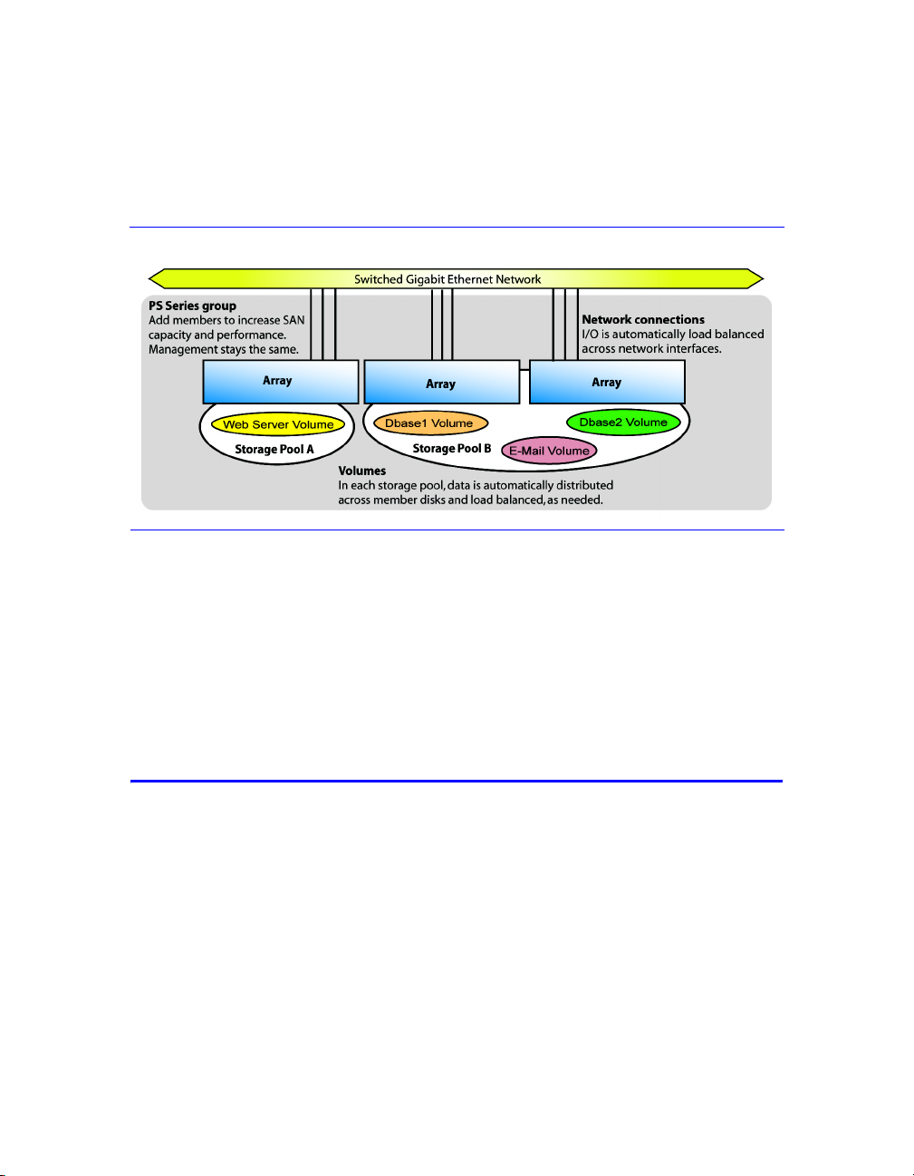
By grouping together one or more PS Series arrays connected to an IP network,
you can create a PS Series group—a highly-scalable iSCSI SAN with a shared
pool of storage space. Integrated virtualization software makes a group easy to
manage and provides automatic RAID configuration, data provisioning, and load
balancing. To increase SAN capacity and performance, connect another array to
the network and add it to the group—data remains online at all times.
To ensure high reliability, PS Series storage arrays include RAID-protected
disks, automatic disk sparing, redundant fans and power supplies, and dual
high-performance control modules, each with three Gigabit Ethernet interfaces
and a battery-backed cache.
A simple setup utility lets you quickly configure an array as a member of a new
or existing group. RAID configuration and load balancing (network and data)
occur automatically. Both graphical and command line user interfaces are
available for group management.
In a multi-member group, you can separate space into storage pools, which allow
you to organize storage according to usage, providing more control over resource
allocation, while maintaining a single system management view.
Using the Group Manager graphical or command line user interface, you create
volumes, assigning to each volume a pool, size, access controls, and other
attributes. A volume can be spread across multiple disks and group members and
is seen on the network as an iSCSI target. Members and volumes can move
between pools to meet business objectives.
To connect to a volume, a host needs only a standards-compliant iSCSI initiator.
Volume access can be restricted through IP address, initiator name, or CHAP
(Challenge Handshake Authentication Protocol) credentials. Once connected, the
volume is seen by the host as a regular disk that can be formatted as usual.
1
PS Series 3000 QuickStart Steps for Setting Up and Using an Array
At a minimum, a group consists of one array with one network connection,
but you can configure three network interfaces for maximum array bandwidth.
Data and network I/O are automatically load balanced across disks and
interfaces—with no impact on data availability.
PS Series Group With Multiple Members
You can easily increase group capacity and bandwidth by adding arrays. When an
array is added to a group, it obtains the group configuration from the existing
members. Once you choose a RAID policy for the member, the pool is
automatically expanded, and volume data and network I/O are load balanced
across the pool members’ disks and network connections. Volumes continue
to be accessible through the same iSCSI targets, and no host modifications are
necessary. Management overhead remains the same, regardless of the group size.
Steps for Setting Up and Using an Array
To start using your PS Series array:
Step 1. Set up the array hardware configuration.
Step 2. Configure the array on the network and create a group.
Step 3. Log in to the group and specify the RAID policy for the array.
Step 4. Create a volume.
Step 5. Connect to the volume from a host system.
2
PS Series 3000 QuickStart Step 1. Set Up the Array Hardware
Step 1. Set Up the Array Hardware
A. Unpack Shipping Box and Gather Hardware
The order in which you unpack the shipping box is important for safety:
1. Open the outer shipping box and remove the accessory box.
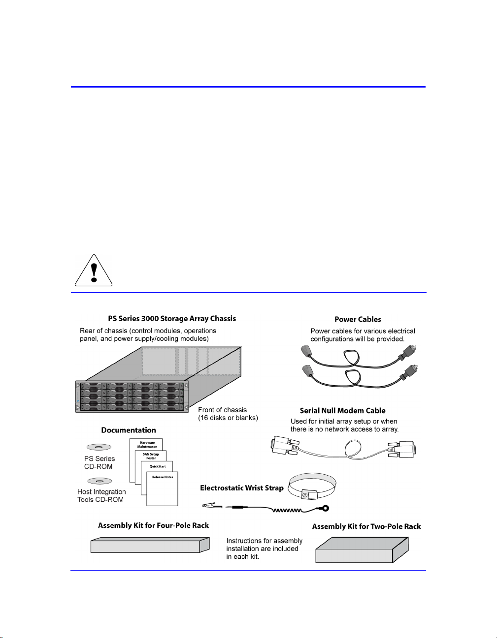
2. Remove the accessories and ensure that you have the contents shown in the
figure Shipping Box Contents.
3. Following the unpacking instructions in the shipping box, lift the array and
place it on a flat surface that is protected from electrostatic discharge. Do not
remove the plastic bag from the array until you are ready to install it in a rack.
4. Gather the hardware that is not included in the box, as described in the table
Required Hardware – Not Supplied.
The array is heavy. Do not attempt to lift or install the array without
assistance.
Shipping Box Contents
3

PS Series 3000 QuickStart Step 1. Set Up the Array Hardware
Description of Shipping Box Contents
Component Description
3U storage array
chassis
Power cables Connects an array to one or more power sources. The shipping
Serial null modem
cable
Four-pole rack
assembly kit
Two-pole rack
assembly kit
Electrostatic wrist strap Protects sensitive hardware from electrical discharge.
Documentation and
CD-ROMs
Contains one or two control modules, two power
supply/cooling modules, and eight or 16 disks.
box may contain multiple power cables to meet the electrical
requirements of the country in which the array will reside.
Caution: Be sure to use only these enclosed power cables with
this product.
Creates a serial connection between an array and a console or
terminal emulator. The cable has two DB9, 9-pin, female
connectors and is used only for the initial member and group
configuration or if there is no network access to the array.
Enables you to install an array in a four-pole rack. Instructions
for assembly are included in the kit.
Enables you to install an array in a two-pole rack. Instructions
for assembly are included in the kit.
Printed documentation includes the PS Series QuickStart,
Hardware Maintenance, Release Notes, and SAN setup poster.
The Group Administration and CLI Reference manuals and
the Group Manager online help are on the documentation
CD-ROM, along with the QuickStart and Hardware
Maintenance manuals.
Host Integration Tools for Windows
documentation are on the HIT CD-ROM.
®
systems and related
License and warranty information is also included in the
shipping box.
Note: Product returns will be accepted only in the original packaging or in
authorized packaging obtained from your PS Series support provider.
4
PS Series 3000 QuickStart Step 1. Set Up the Array Hardware
Array installation also requires the hardware described in Required Hardware –
Not Supplied. This hardware is not provided with your array.
Required Hardware – Not Supplied
Component Description
Standard 19” twoor four-pole rack
One or more
network cables
Network switch Connects devices to a network. If possible, connect the array to
Computer or a
console terminal
Provides easy access to storage arrays and other hardware in your
computing environment.
Connects an array to a network switch. Use Category 5E or
Category 6 cables with RJ45 connectors. You can also use
Category 5 cables if they adhere to the TIA/EIA TSB95 standard.
Only one network connection is required for operation, but as
many as six connections (maximum of three active) are possible.
different switches for high availability.
Enables you to perform the initial array and group configuration or
manage the group when there is no active network connection. A
computer must be running a terminal emulator.
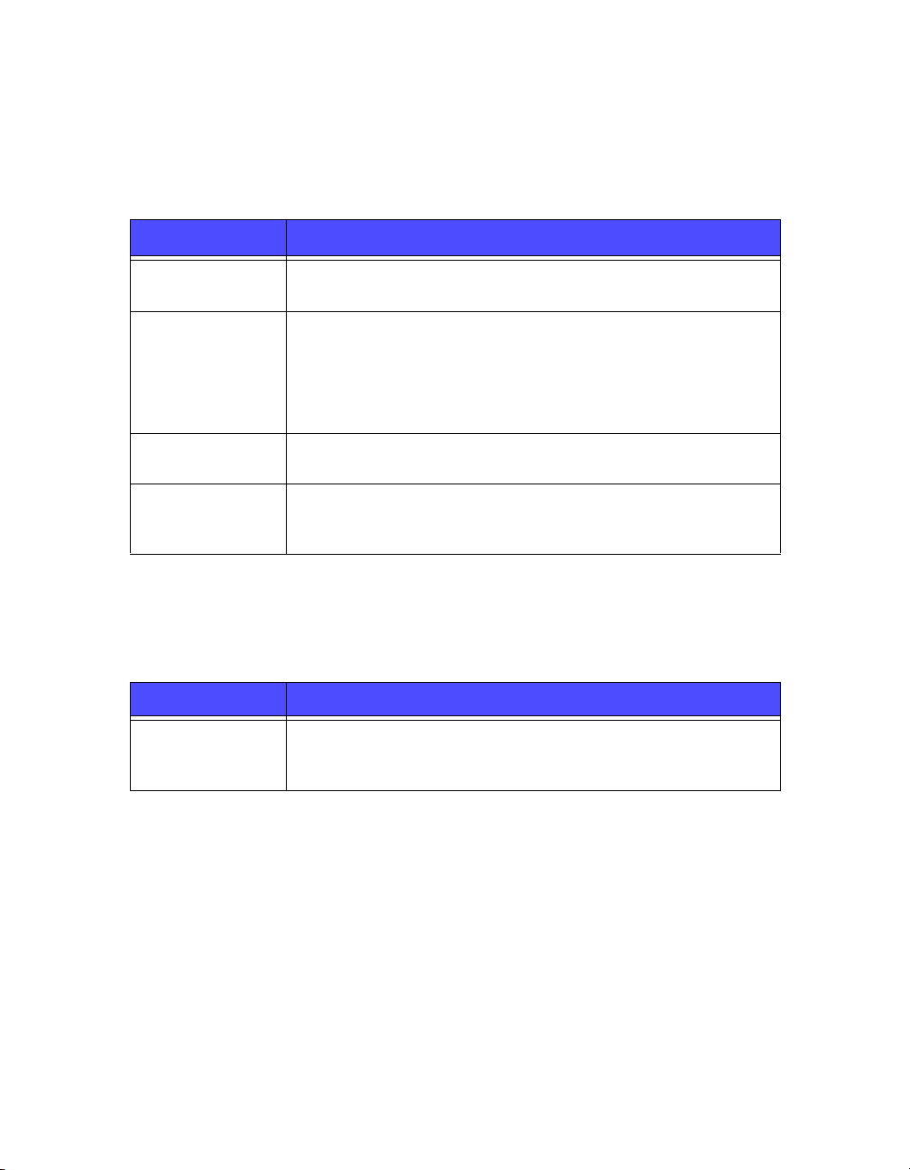
The following table describes the optional hardware that you can use in a storage
array installation. This hardware is not provided with your array.
Optional Hardware – Not Supplied
Component Description
One or two UPS
systems
Provide a highly available source of power to an array. Each UPS
system should be on a different circuit and must provide the correct
type of voltage for an adequate amount of time.
5

PS Series 3000 QuickStart Step 1. Set Up the Array Hardware
B. Mount Array in a Stable Rack
A PS Series array must be mounted in a two-pole or four-pole 19” rack.
Instructions for rack assembly and mounting an array are included with the
two-pole assembly kit and the four-pole assembly kit in the array shipping box.
When mounting an array in a rack, you must meet the following recommendations
and requirements:
• Be sure there is sufficient space for air flow in front of and behind the array.
• It is recommended that you attach the rack to the floor for added stability.
• Be sure to support the array until it is completely mounted in the rack.
• The location of the array must be properly vented and must meet the
environmental, power, and physical requirements described in the
following table.
PS Series Storage Array Requirements
Component Requirement
Weight of fully-loaded array 80 pounds or 36.36 kilograms
Operating temperature 41 to 104 degrees F / 5 to 40 degrees C
Storage temperature -22 to 140 degrees F / -30 to 60 degrees C
Maximum altitude 10,000 feet
Operational relative humidity 8 to 90% non-condensing
Thermal output of fully-loaded array 2200 BTU/hour, 660 watts
Shock 30 G for 2 ms
Vibration .1 G @ 10 to 100 hertz
Input voltage 90 to 264 VAC (auto-sensing)
Input current 5.5 amperes (maximum, single power supply)
@ 120 volts
Input frequency 50 to 60 hertz
Input power 660 VA
Power supplies Dual, 450 watts DC output
Height/Width/Depth 5.25” x 17 5/8” x 22.5”
13.33 cm x 44.77 cm x 56.25 cm
6
PS Series 3000 QuickStart Step 1. Set Up the Array Hardware
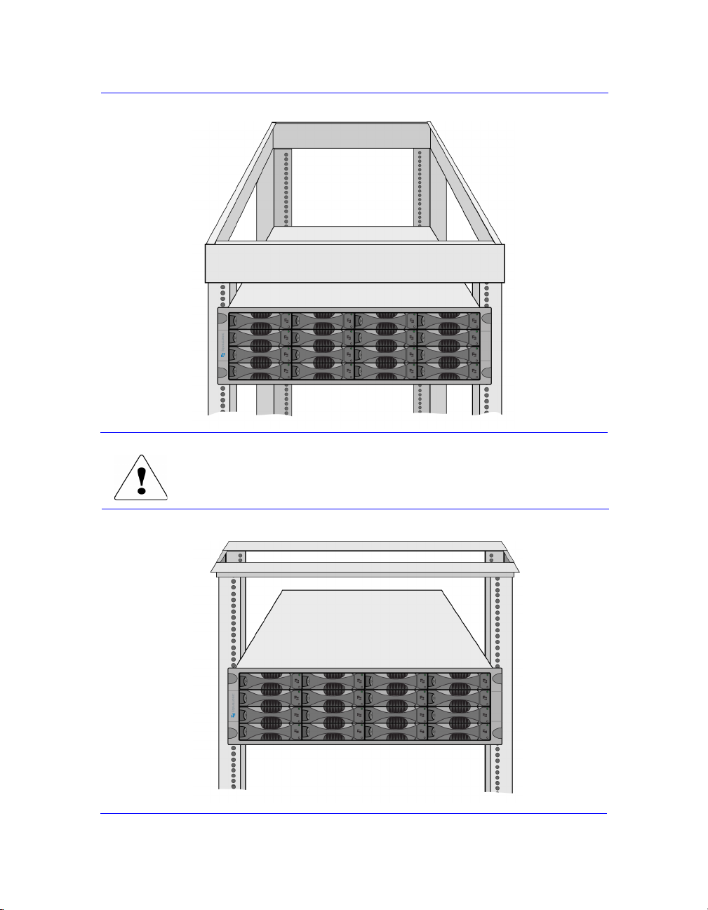
Four-Pole Rack Example
Be sure to support the array until it is completely mounted
in the rack.
Two-Pole, Mid-Mount Rack Example
7

PS Series 3000 QuickStart Step 1. Set Up the Array Hardware
C. Connect Power Cables for Grounding
A PS Series array includes two power supply/cooling modules. It is recommended
that you connect both power supplies to different sources of power, preferably on
separate circuits for increased availability.
For a highly-available power configuration, connect one power supply to an
uninterruptible power supply (UPS) system, and connect the other power supply
to a different source of power. See the table PS Series Storage Array Requirements
on page 6 for information about voltage requirements.
Notes: Do not turn on power to the array. At this time, the power cables are only
for grounding purposes.
If your PS Series array was shipped with power cables, use these cables to
meet safety requirements.
To connect power cables to an array, refer to the figure shown next. Be sure to use
the cable strain relief when securing the power cable in the array.
Connecting Power Cables
8

PS Series 3000 QuickStart Step 1. Set Up the Array Hardware
D. Connect Array to a Network Switch
A PS Series array includes one or two control modules. Only one control module
is active (serving network traffic) at one time. The secondary (redundant) control
module mirrors cache data from the active control module. If the active control
module fails, the secondary will take over network operations.
Each control module has three Ethernet network interface ports, labeled PORT 0,
PORT 1, and PORT 2, for up to three active connections to the network.
In addition to the requirements and recommendations described in the following
tables, all the usual rules for proper network configuration apply to the group
members. General network configuration is beyond the scope of this document.
Network Requirements
Requirement Description
One or more
network connections
Correct network
cables
An array must have at least one functioning network interface
connected to a network (through a network switch, if possible).
When you configure the array, as described later in this
QuickStart, you assign an IP address and netmask to this interface.
In a dual control module array, to ensure network availability
regardless of which control module is active, connect a cable to
the network interface port on each control module.
Use Category 5E or Category 6 cables with RJ45 connectors. You
can also use Category 5 cables if they adhere to the TIA/EIA
TSB95 standard.
Network Recommendations
Recommendation Description
Switched Gigabit
Ethernet network
Multiple network
connections
Connect arrays and hosts to a switched network and ensure that all
network connections between hosts and arrays are Gigabit
Ethernet. An array can operate at 10 and 100 Mbits, but
performance will be significantly degraded.
For increased bandwidth and availability, connect multiple
network interfaces to the network (and different switches, if
possible). Connect interfaces in the following order: PORT 0,
PO RT 1, and PORT 2.
After the initial setup, use the Group Manager GUI or CLI to
assign an IP address and netmask to each additional interface.
9

PS Series 3000 QuickStart Step 1. Set Up the Array Hardware
Network Recommendations (Continued)
Recommendation Description
Access to the group
IP address
Redundant network
paths
For replication, a
reliable, adequately
sized network link
No STP
functionality on
switch ports that
connect end nodes
Flow Control
enabled on switches
and NICs
Unicast storm
control disabled on
switches
Jumbo Frames
enabled on switches
and NICs
VLANs Configure switches to use VLANs in order to separate iSCSI SAN
In a multi-subnet group, each configured network interface should
have access to the subnet on which the group IP address resides.
Using a multipathing solution helps to ensure that no single point
of failure exists between hosts and arrays.
For effective and predictable replication, be sure that the network
link between the primary and secondary groups is reliable and
provides sufficient bandwidth for copying data.
Do not use Spanning-Tree (STP) on switch ports that connect end
nodes (iSCSI initiators or storage array network interfaces).
However, if you want to use STP or RSTP (preferable to STP),
you should enable the port settings available on some switches
that let the port immediately transition into STP forwarding state
upon link up. This functionality can reduce network interruptions
that occur when devices restart, and should only be enabled on
switch ports that connect end nodes.
Note: The use of Spanning-Tree for a single-cable connection
between switches is encouraged, as is the use of trunking
for multi-cable connections between switches.
Enable Flow Control on each switch port and NIC that handles
iSCSI traffic. PS Series arrays will correctly respond to Flow
Control.
Disable unicast storm control on each switch that handles iSCSI
traffic, if the switch provides this feature. However, the use of
broadcast and multicast storm control is encouraged on switches.
Enable Jumbo Frames on each switch and NIC that handles iSCSI
traffic to obtain any performance benefit and ensure consistent
behavior.
traffic from other network traffic.
10

PS Series 3000 QuickStart Step 1. Set Up the Array Hardware
The minimum network configuration for a single control module array is one
network connection to PORT 0. The minimum network configuration for a dual
control module array is one network connection to PORT 0 on each control
module, as shown in the figure Minimum Dual Control Module Network
Configuration. This configuration protects against control module failure.
Minimum Dual Control Module Network Configuration
For maximum network bandwidth and availability, connect cables to all network
ports and distribute the connections across multiple network switches, as shown in
the figure High Performance, High-Availability Network Configuration.
High Performance, High-Availability Network Configuration
11

PS Series 3000 QuickStart Step 1. Set Up the Array Hardware
E. Turn on Power to Array and Check LEDs for Errors
Before turning on power, be sure the array is at room temperature. If an LED
indicates a problem, contact the support provider for your PS Series array.
Disk LEDs
Backpanel LEDs
Disk LED Descriptions
Disk LEDs Color Description
Top Off No power or error condition.
Green Power.
Flashing green Disk activity.
Bottom Off No power or normal condition.
Red Error condition.
Operations Panel LED Descriptions
Operations LEDs Color Description
Power (upper right) Off No power.
Green Power.
12

PS Series 3000 QuickStart Step 1. Set Up the Array Hardware
Operations Panel LED Descriptions (Continued)
Operations LEDs Color Description
Array locator (upper
left)
Warning condition
(lower left)
Error condition
(lower right)
Off No power or normal condition.
Flashing orange Administrator enabled the array locator function.
Off No power or normal condition.
Flashing orange One or more of the following has occurred:
• RAID set is degraded but still functioning.
• RAID set (volume level) has lost blocks.
• Component temperature is near a limit.
• Fan has failed or RPMs exceed opper or
lower limit.
• Power supply is not installed or has no power.
• Only one control module installed or control
module has failed over.
• Active control module syncing with
secondary.
• No communication between control modules.
• No replication progress for more then 1 hour.
• Installed spare disk does not have enough
capacity to replace a disk in a RAID set.
• A non-critical hardware component failed.
Off No power or normal condition.
Flashing orange One or more of the following has occurred:
• RAID is not functioning.
• Lost block table is full.
• Temperature exceeds upper or lower limit.
• Control module cache has lost data.
• One or both fan trays are not installed.
• Both fans on a fan tray have failed.
• Cache battery has less than 72 hours of charge
or temperature is too high to charge battery.
• NVRAM coin cell battery has failed.
• Cache contains data that does not belong to
any of the installed disks.
• More than one valid RAID set exists in array.
• Control modules are different models.
• A critical hardware component has failed.
• Operations panel failed or not installed.
• Storage enclosure processor that monitors
array components has experienced a failure.
13

PS Series 3000 QuickStart Step 1. Set Up the Array Hardware
Control Module LED Descriptions
Control Module LEDs Color Description
ACT Off No power, secondary control module is not
synchronized with active control module,
or error condition.
Green Active control module (serving network I/O).
Orange Secondary control module; cache is
synchronized with active control module.
ERR Off No power or no error condition.
Red Array is starting up or error condition.
PWR Off No power.
Green Power.
Network Interface LED Descriptions
Network Interface LEDs Color Description
Left Off
Green Connected to network.
Right Off No power or not transmitting.
Green Transmitting.
No power or not connected to network.
Power Supply/Cooling Module LED Descriptions
Power Supply/Cooling
Module LED
_ _ _
____
~
14
Color Description
Off No power or normal condition
Orange DC power failure
Off No power or normal condition
Orange Fan failure
Off No power or normal condition
Orange AC power failure
Off No power
Green Normal array operation

PS Series 3000 QuickStart Step 1. Set Up the Array Hardware
F. Connect Array to a Console Terminal
Establish a serial connection between the array and a console terminal (or a
computer running a terminal emulator) to run the
you to configure the array and add it to a group. After setting up the array, the
serial connection is not needed, but you should keep the serial cable. You can use
a serial connection if there is no network access to the group or array.
Note: If you have a Microsoft
®
Windows® system, you can use the EqualLogic
Remote Setup Wizard to configure an array and create a group instead of
using the
setup utility. The wizard does not require the serial cable.
The serial connection must have the following characteristics:
• 9600 baud
•One STOP bit
• No parity
• 8 data bits
• No hardware flow control
To create a serial connection, obtain the null modem cable that shipped with the
array and refer to the next figure. The serial cable must always be connected to
Serial Port 0 on the active control module (ACT LED will be green).
setup utility, which enables
Connecting the Serial Cable
15

PS Series 3000 QuickStart Step 2. Configure the Array and Create a Group
Step 2. Configure the Array and Create a Group
The setup utility enables you to configure a storage array on the network and
create a PS Series group with the array as the first member. The utility prompts for
the array’s network configuration and the group configuration, including the
group IP address.
Note: See the tables Network Requirements and Network Recommendations on
page 9 for additional network information.
After the
setup utility completes, the group is available on the network. Next, log
in to the group using the Group Manager GUI or CLI and set the RAID policy for
the first member.
A. Before running the
setup utility, gather the information described in the
Member Configuration and Group Configuration tables shown below. Obtain
IP addresses from your network administrator, as needed.
Member Configuration
Prompt Description
Member name Unique, descriptive name (up to 64 alphanumeric characters; no
spaces). First character must be a letter or number. Used to
identify and administer the array.
Network interface Name of a network interface (either
connected to a functioning port on a network switch.
IP address Network address for the named network interface.
Note: Each member must have at least one network interface on
the same subnet as the group IP address.
Netmask Combines with the IP address to identify the subnet on which the
named network interface resides (default is 255.255.255.0).
Default gateway
(optional)
Network address for the device used to connect subnets and
forward network traffic beyond the local network. A default
gateway is needed only if you want the named network interface
to communicate outside the local network (for example, to allow
access to volumes from hosts outside the local network).
Note: The default gateway must be on the same subnet as the
named network interface.
eth0, eth1, or eth2) that is
16

PS Series 3000 QuickStart Step 2. Configure the Array and Create a Group
Group Configuration
Prompt Description
Group name Name of the group (up to 54 characters). Valid characters include
letters, number, and dashes. The first character must be a letter or
number. Identifies the group for the purposes of adding new
members or setting up replication.
Group IP
address
Password for
managing group
membership
Password for the
default group
administration
account
Network address for the group. The group IP address is used for
group administration and host access to data stored in the group.
Password required when adding members to the group. The
password must have 3 to 16 alphanumeric characters and is
case-sensitive.
Password that will override the factory-set password (
for the default
16 alphanumeric characters and is case-sensitive.
grpadmin account. The password must have 3 to
grpadmin)
B. Using the serial connection you established in Step 1-F on page 15, press the
key. At the login prompt, enter the
factory-set password, which is also
echoed on the screen.
grpadmin account name and the
grpadmin. Note that passwords are not
Login: grpadmin
Password: grpadmin
Welcome to Group Manager
Copyright 2001-2006 EqualLogic, Inc.
It appears that the storage array has not been configured.
Would you like to configure the array now? (y/n) [n] y
C. If you respond by typing y and pressing the key, the following dialog
appears. You can also enter
n and, at a later time, type setup at the console
prompt (>). The utility prompts for the member and group configuration.
Press the key to accept a default value. Enter ? to obtain help.
17

PS Series 3000 QuickStart Step 2. Configure the Array and Create a Group
An example of running the setup utility is shown next. There may be a short
delay after entering the group IP address as the array searches the network.
Example of Configuring an Array and Creating a Group
Group Manager Setup Utility
The setup utility establishes the initial network and storage
configuration for a storage array and then configures the array
as a member or a new or existing group of arrays.
For help, enter a question mark (?) at a prompt.
Do you want to proceed (yes | no) [no]? yes
Initializing. This may take several minutes to complete.
Enter the network configuration for the array:
Member name []: member01
Network interface [eth0]: eth0
IP address for network interface []: 192.17.2.41
Netmask [255.255.255.0]:
Default gateway [192.17.2.1]:
Enter the name and IP address of the group that the array will join.
Group name []: group01
Group IP address []: 192.17.2.40
Searching to see if the group exists. This may take a few minutes.
The group does not exist or currently cannot be reached. Make sure
you have entered the correct group IP address and group name.
Do you want to create a new group (yes | no) [yes]? yes
Group Configuration
Group Name: group01
Group IP address: 192.17.2.40
Do you want to use the group settings shown above (yes | no) [yes]: yes
Password for managing group membership:
Retype password for verification:
Password for the default group administration account:
Retype password for verification:
Saving the configuration ...
Waiting for configuration to become active......Done
Group member member01 now active in the group.
Group group01 has been created with one member.
Use the Group manager GUI or CLI to set the RAID policy for the member.
You can then create a volume which a host can connect to using an iSCSI
initiator.
18

PS Series 3000 QuickStart Step 3. Set the RAID Policy
Step 3. Set the RAID Policy
After you create the group, use the Group Manager GUI or CLI to set the RAID
policy for the member. This will configure the disks automatically according to
the selected RAID policy, with the appropriate number of spare disks.
Once you set the RAID policy, volume data can be stored on the member.
Until the RAID configuration completes, performance will not be optimal,
but the group is fully operational.
You can convert a member to a different RAID policy only if the new policy
requires less disk space than the current policy.
Using the GUI to Set the RAID Policy
To start the GUI, specify the group IP address in a Web browser. When prompted,
log in to the group by entering the
you specified when creating the group. The Group Summary window appears,
displaying the current group configuration and storage pool capacity.
Initially, the Group Summary window will display a message that a member exists
with an unconfigured RAID policy. This is normal.
grpadmin account name and the password that
Group Summary – RAID Policy Not Set
19

PS Series 3000 QuickStart Step 3. Set the RAID Policy
If you place the mouse over the unconfigured member, the following pop-up is
displayed, indicating a normal health status.
Not Configured Pop-Up
To set the RAID policy for the member, expand
Members in the far left panel and
select the member name. The following warning appears.
Warning RAID Not Configured
Yes and the Configure Member – General Settings dialog box appears.
Click
Configure Member – General Settings
20

PS Series 3000 QuickStart Step 3. Set the RAID Policy
Click Next to continue. The Configure Member – RAID Set Configuration dialog
box appears.
Configure Member – RAID Set Configuration (RAID-50)
Specify the RAID policy by selecting one of the buttons under RAID policy:
RAID-10 — Striping on top of multiple RAID 1 (mirrored) sets, with two
•
spare disks. RAID-10 provides good performance for random writes, in
addition to the highest availability. However, since the disks are mirrored,
RAID-10 provides the least capacity.
•
RAID-50 — Striping on top of two RAID 5 (distributed-parity) sets, with two
spare disks. RAID-50 provides a good balance of performance (especially for
sequential writes), availability, and capacity.
RAID-5 — One RAID 5 set, with one spare disk. RAID-5 is similar to
•
RAID-50, with more capacity (two additional disks) but lower availability
and performance.
The values in the dialog box table reflect the pool capacity, based on the selected
RAID policy. In the preceding dialog box, selecting RAID-50 yields an estimated
member capacity of 3.14 TB. Selecting RAID-10 yields an estimated member
capacity of 1.83 TB, as shown in the following dialog box.
21

PS Series 3000 QuickStart Step 3. Set the RAID Policy
Configure Member – RAID Set Configuration (RAID-10)
Select the desired RAID policy and click
Next to continue. The Configure
Member – Summary dialog box appears.
Configure Member – Summary
If the member configuration is satisfactory, click Finish. The following window
shows a completed configuration for a one-member group.
22

PS Series 3000 QuickStart Step 3. Set the RAID Policy
Group Summary – Completed Member Configuration
Using the CLI to Set the RAID Policy
To access the CLI, establish a telnet or SSH connection to the group IP address or
use a serial connection to the array, as described in Step 1-F on page 15. When
prompted, log in to the group by entering the
password that you specified when creating the group.
grpadmin account name and the
To set the RAID policy for a member, use the following command format:
member select member_name raid-policy raid_policy
The raid_policy variable can be one of the following:
RAID-10 — Striping on top of multiple RAID 1 (mirrored) sets, with one or
•
two spare disks. RAID-10 provides good performance for random writes, in
addition to the highest availability. However, since the disks are mirrored,
RAID 10 provides the least capacity.
•
RAID-50 — Striping on top of two RAID 5 (distributed-parity) sets, with
one or two spare disks. RAID-50 provides a good balance of performance
(especially for sequential writes), availability, and capacity.
RAID-5 — One RAID 5 set, with one spare disk. RAID-5 is similar to
•
RAID-50, with more capacity (two additional disks) but lower availability
and performance.
23

PS Series 3000 QuickStart Step 3. Set the RAID Policy
• raid10-nospares — Striping on top of multiple RAID 1 sets, with no
spares, if possible. This policy should be used only at installations where extra
disks and personnel are available at all times to replace failed disks.
Note: This option is available only with the CLI.
raid50-nospares — Striping on top of two RAID 5 sets, with no spares,
•
if possible. This policy should be used only at installations where extra disks
and personnel are available at all times to replace failed disks.
Note: This option is available only with the CLI.
For example, the following command specifies a RAID policy of RAID-50 for a
member:
> member select member01 raid-policy raid50
24

PS Series 3000 QuickStart Step 4. Create a Volume
Step 4. Create a Volume
After setting the RAID policy for a member, you can create one or more volumes.
For each volume, you must specify:
• Name. Unique name used to manage the volume, up to 64 characters. Valid
characters include letters, numbers, periods, hyphens, and colons.
• Size. Amount of group space to allocate to the volume.
Optionally, you can override the following default snapshot settings for the
volume:
• Snapshot reserve. Amount of group space, as a percentage of the volume
size, to reserve for snapshots. The default is 100 percent of the volume size.
• Warning alarm. By default, an alarm is generated when the amount of free
snapshot space is less than 10 percent of the total reserved snapshot space.
• Snapshot space recovery policy. Action to take automatically when the
volume’s reserved snapshot space has been exceeded: either delete the oldest
snapshot (default) or put the volume and all its snapshots offline.
In addition, you must create access control records to allow authorized hosts
access to a volume, while denying other hosts access. A volume and its snapshots
share a list of records (up to 16).
An access control record can apply to the volume, its snapshots, or both. For
example, you may want to give one host access to both the volume and its
snapshots and give another host access only to the volume snapshots.
In each access control record, you can specify an IP address, iSCSI initiator name
or CHAP user name (or any combination of the three). To access a volume or
snapshot, a host must exactly meet all the requirements in one access control
record.
25

PS Series 3000 QuickStart Step 4. Create a Volume
Using the GUI to Create a Volume
To start the GUI, specify the group IP address in a Web browser. When prompted,
log in to the group by entering the
you specified when creating the group. The Group Summary window appears,
displaying the current group configuration and storage pool capacity.
Group Summary – No Volumes
grpadmin account name and the password that
Note: To obtain GUI and CLI help from the EqualLogic website, click
the bottom left corner of the GUI and then click
Online Help. You can
Tools in
also copy the help files from the PS Series documentation CD-ROM to the
system running the Web browser and then specify a local online help
location by clicking
To create a volume, click
User Preferences in the Tools menu.
Create volume in the Activities panel. The
Create Volume – General Settings dialog box appears. Enter the following:
•
Volume name — Unique name, up to 64 alphanumeric characters (including
periods, hyphens, and colons).
•
Volume size — Be sure to select the correct unit (by default, gigabytes).
Snapshot reserve — Amount of snapshot space to reserve for the volume
•
(by default, 100% of the volume size). To change the snapshot space warning
threshold and snapshot space recovery policy, you must modify the volume.
The values in the storage pool space table in the dialog box reflect the specified
volume size and snapshot reserve size.
26

PS Series 3000 QuickStart Step 4. Create a Volume
Create Volume – General Settings
Click
Next to display the Create Volume – iSCSI Access dialog box. Specify the
IP address, CHAP user name, or iSCSI initiator name to which the volume will be
restricted. In the following dialog box, volume access is restricted to IP address
172.17.1.40. You can set up more access controls after creating the volume.
Create Volume – iSCSI Access
27

PS Series 3000 QuickStart Step 4. Create a Volume
Click Next to display the Create Volume – Summary dialog box. If the volume
configuration is satisfactory, click
Finish to create the volume.
Create Volume – Summary
Once you create a volume, you can create snapshots of the volume or perform
other tasks. The following window shows a group with volumes and snapshots.
Group Summary – With Volumes
28

PS Series 3000 QuickStart Step 4. Create a Volume
Using the CLI to Create a Volume
To access the CLI, establish a telnet or SSH connection to the group IP address or
use a serial connection to the array, as described in Step 1-F on page 15. When
prompted, log in to the group by entering the
password that you specified when creating the group.
To create a volume, use the following command format:
volume create volume_name size[GB] [option]
Specify the volume name and size (the default is megabytes).
grpadmin account name and the
Optionally, specify one or more of the following for the
• snap-reserve percent_volume_size
• snap-depletion delete-oldest | volume-offline
• snap-warn percent_reserve_size
• unrestricted
option variable:
The unrestricted option sets no restrictions on host access to the volume,
which is not recommended. Instead, to restrict host access to the volume, create
one or more access control records using the following command format:
volume select volume_name access create access_control
The access_control variable can be one or more of the following:
•
initiator initiator_name
•
ipaddress ip_address
•
username chap_username authmethod chap
The following example creates a 50 GB volume and two access control records
for the volume. Only a host that has IP address 112.15.7.119 or 112.15.12.120 will
be able to access the volume and its snapshots.
> volume create staff1 50GB
> volume select staff1 access create ipaddress 112.15.7.119
> volume select staff1 access create ipaddress 112.15.12.120
29

PS Series 3000 QuickStart Step 5. Connect to the Volume from a Host System
Step 5. Connect to the Volume from a Host System
A PS Series group volume is seen on the network as an iSCSI target. When you
create a volume, its iSCSI target name is generated automatically. An example of
an iSCSI target name for a volume named
iqn.2001-05.com.equallogic.5-4a0900-2f00000-007eca92d654f160-dbvol
To display the iSCSI target name for a volume, do either of the following:
dbvol is as follows:
• In the CLI, enter the command:
volume show volume_name
• In the GUI, select the volume name in the far left panel and then click the
Status tab to display the iSCSI target name at the bottom of the iSCSI
Connections panel.
To connect to a volume, the host must have an iSCSI initiator running and must
match the security credentials in one of the volume’s access control records.
Hardware and software initiators are available from a variety of vendors.
Configure your initiator using the instructions provided by the vendor.
Note: It is strongly recommended that you visit the EqualLogic Customer
Support website to obtain important information about using initiators to
access PS Series group volumes.
The exact procedure for connecting to an iSCSI target depends on the initiator.
See the initiator documentation for details. In most cases, you use the initiator
configuration utility to specify the group IP address as either the target portal
or the discovery address. If the initiator supports the discovery process, it will
return a list of iSCSI targets (volumes) that the host can access.
If the initiator does not support discovery, you must also specify the target name.
The standard iSCSI port number (3260) may also be required.
Using the initiator configuration utility, select the desired target and log in or
connect to the target. If the volume’s access control records use CHAP for initiator
authentication, enter the CHAP credentials (user name and password or “secret”)
at this time. Note that CHAP must already be set up in the group, as described in
the PS Series Group Administration manual.
Once the host connects to the iSCSI target, the volume is seen by the host as a
regular disk that can be formatted using the normal operating system utilities. For
example, you can partition the disk and create a file system, if desired.
30

PS Series 3000 QuickStart Advanced Operations and More Information
Advanced Operations and More Information
After getting started, you can customize a PS Series group and also utilize the full
set of product features and host-based solutions.
You can also obtain technical support. For more information, see Product
Documentation and Technical Support on page vi.
The following table lists advanced operations. These group, volume, and member
tasks are fully documented in the Group Administration manual.
Advanced Operations
Group Task
Add a member. Although a one-member group is fully functional, adding
Modify the date, time, or
time zone or configure
NTP.
Create administration
accounts.
Set up event notification. To be informed of significant events in a timely manner, set
Configure iSNS. To automate iSCSI target discovery, you can configure the
Configure CHAP. You can use CHAP to restrict host access to volumes. Both
Configure SNMP. To monitor traps from the group, you can use SNMP.
Create pools. With multi-member groups, you can create additional pools
Description
more arrays expands storage pool capacity, increases
network bandwidth, and improves overall group
performance—without disrupting data availability.
Group time is based on the clock on the first member, which
is set at the factory. The default time zone is EST. You can
also configure the group to use an NTP server.
The
grpadmin account is the default administration
account. You can set up additional accounts.
up e-mail or syslog notification.
group to use an iSNS server.
initiator and target CHAP authentication are supported.
and assign members and volumes to the pools.
31

PS Series 3000 QuickStart Advanced Operations and More Information
Advanced Operations (Continued)
Volu m e Ta sk
Create access control
records for a volume.
Create snapshots of a
volume.
Set up replication across
different groups.
Clone a volume, snapshot,
or replica.
Promote a replica set. Promotion stops replication, creates a new volume, and
Create collections. Collections provide a way to group multiple related
Member Task
Add network connections. Multiple connections provide performance and availability.
Add disks. Adding disks increases capacity.
Description
An access control record specifies the criteria that a host
must meet in order to access the volume.
Snapshots are point-in-time copies of volume data that can
be used for backups.
Replicas are point-in-time copies of volume data that are
stored separately from volumes for disaster recovery.
Cloning creates a new volume in the group where the cloned
volume, snapshot, or replica resides.
transforms the replicas into corresponding snapshots.
volumes together for the purpose of creating snapshots or
replication. The administrator can the create a multi-volume
snapshot or replica in a single operation or through a single
schedule.
Description
32


Index
A
access control records, using 25
array
adding to a group 16
configuration prompts 16
configuring 16
console connection 15
creating a group 16
documentation vi
environment requirements 6
LED descriptions 12
maximum network configuration
11
network address 16
network connection guidelines 9
network recommendations 9
network requirements 9
password for logging in 17
power requirements 6
power supply connections 8
powering on 12
rack mounting 6
serial connection 15
setting the RAID policy 19
steps for setting up and using 2
unpacking 3
warranty vii
C
CHAP
specifying host credentials 30
using access control records 30
CLI, accessing 23
collections, defined 32
console connection (serial) 15
control modules
connecting cables 9
network connections 9
D
default gateway (member) 16
documentation, array vi
F
Flow Control recommendation 10
G
Gigabit Ethernet recommendation 9
group
accessing the CLI from a host 23
accessing the GUI from a host 19
accessing volumes from a host 30
advanced operations 31
configuration prompts 17
creating 16
creating volumes 25
customizing 31
defined 1
increasing capacity 2
IP address 17
name 17
network recommendations 9
network requirements 9
online help 26
password for adding members 17
password for managing 17
GUI, accessing 19
35

PS Series 3000 QuickStart Index
H
hardware
console connection 15
environment requirements 6
LED descriptions 12
network connections 9
power supply connections 8
powering on array 12
rack mounting array 6
required 4, 5
serial connection 15
setting up 3
shipping box contents 3, 4
unpacking 3
hosts
accessing CLI 23
accessing GUI 19
accessing volumes 25
connecting to volumes 30
Flow Control recommendation 10
Jumbo Frames recommendation 10
restricting access 25
specifying CHAP credentials 30
I
initiator (iSCSI)
accessing a volume 30
defined 1
host requirements 30
J
M
member
adding to a group 16
configuring 16
defined 1
increasing bandwidth 9
increasing capacity 2
multipath I/O recommendation 10
network address 16
network cable requirement 9
network connection guidelines 9
network connection requirement 9
setup prompts 16
subnet access recommendation 10
N
netmask (member) 16
network
array IP address 16
cables 9
connecting arrays 9
connection guidelines 9
group IP address 17
improving performance 9
maximum configuration 11
recommendations 9
requirements 9
network interfaces
connecting 11
description 9
Jumbo Frames recommendation 10
L
LEDs, location and description 12
36
O
online help, accessing 26

PS Series 3000 QuickStart Index
P
passwords
for adding a member 17
for logging in to group 17
power supplies
connecting array 8
turning on 12
using UPS systems 8
product return requirements 4
R
rack mounting array
four-pole rack 6
two-pole rack 6
RAID 10, defined 21
RAID 5, defined 21
RAID 50, defined 21
RAID policy, setting 19
S
serial connection, setting up 4, 15
setup utility
array configuration prompts 16
creating a group 16
example of creating a group 18
group configuration prompts 17
shipping box contents 3, 4
Spanning-Tree recommendation 10
spares
set as part of RAID policy 19
storage pools, defined 1
switches, recommendations
Flow Control 10
Jumbo Frames 10
Spanning-Tree 10
unicast storm control 10
VLAN 10
T
target (iSCSI)
connecting to 30
defined 1
obtaining name 30
U
unicast storm control recommendation
10
UPS systems, using for availability 8
V
VLAN recommendation 10
volumes
accessing from a host 30
connecting to 30
creating 25
defined 1
requirements 25
restricting access 25
snapshot settings 25
target name for 30
W
warranty, array vii
37


 Loading...