

Page 1
Hardware Maintenance
Hardware Maintenance
Page 2

Copyright © 2007 EqualLogic, Inc.
May 2007
EqualLogic is a registered trademark of EqualLogic, Inc.
All trademarks and registered trademarks mentioned herein are the property of their
respective owners.
Possession, use, or copying of the documentation or the software described in this
publication is authorized only under the license agreement.
EqualLogic, Inc. will not be held liable for technical or editorial errors or omissions
contained herein. Information in this document is subject to change.
Part Number: 110-0041-R3
ii
Page 3

Table of Contents
Preface ..................................................................................................................v
Audience ..........................................................................................................v
Organization ....................................................................................................v
Conventions ....................................................................................................vi
Documentation and Technical Support ..........................................................vi
Warranty Information ....................................................................................vii
Restricted Access Requirement .....................................................................vii
Regulatory Agency Notices ........................................................................ .viii
1 Basic Array Information............................................................................... 1-1
Array Front and Back Panels........................................................................ 1 -1
Interpreting Operations Panel LEDs ............................................................ 1-2
Using an Electrostatic Wrist Strap ............................................................... 1-4
Shutting Down and Restarting an Array ...................................................... 1-4
2 Maintaining Disks.......................................................................................... 2-1
Interpreting Disk LEDs................................................................................ 2-1
Disk Handling Requirements ....................................................................... 2-2
Identifying Failed Disks................................................... ..... .... ..... .............. 2-3
Removing Disks........................................................................................... 2-3
Installing Disks.............................................................................................2-5
3 Maintaining Control Modules...................................................................... 3-1
Supported Control Modules ......................................................................... 3-1
Interpreting Control Module LEDs.............................................................. 3-2
Control Module Handling Requirements..................................................... 3-3
Identifying Control Module Failures............................................................ 3-3
Understanding Failover Behavior ................................................................ 3-3
Maintaining Control Module Firmware....................................................... 3-4
Connecting Network Cables......................................................................... 3-5
Removing a Control Module........................................................................ 3-7
Installing a Control Module ......................................................................... 3-9
Replacing the Compact Flash Card............................................................ 3-11
4 Maintaining Power Supply and Cooling Modules...................................... 4-1
Interpreting Power Supply and Cooling Module LEDs............................... 4-1
Identifying Power Supply and Cooling Module Failures............................. 4-2
Removing a Power Supply and Cooling Module......................................... 4-2
iii
Page 4

PS3000 Series Hardware Maintenance Table of Contents
Installing a Power Supply and Cooling Module .......................................... 4-4
A Environmental, Power, and Other Specifications......................................A-1
Index............................................................................................................Index-1
iv
Page 5

Preface
This manual describes how to maintain the hardware for PS3000 Series arrays
from EqualLogic. Each array contains hot-swappable power supply and cooling
modules, up to sixteen RAID-protected disks, and single or dual
hot-swappable control modules.
With one or more PS Series arrays, you can create a PS Series group—a selfmanaging, iSCSI storage area network (SAN) that is affordable and easy to use,
regardless of scale. To install hardware, see the PS3000 Series QuickStart.
Audience
This manual is designed for the administrators responsible for maintaining
PS3000 Series hardware. Administrators are not required to have extensive
network or storage system experience. However, it may be useful to understand:
• Basic networking concepts
• Current network environment
• User disk storage requirements
• RAID configurations
• Disk storage management
Note: Although this manual provides examples of using PS Series arrays in some
common network configurations, detailed information about setting up a
network is beyond its scope.
Organization
This manual is organized as follows:
• Chapter 1, Basic Array Information, describes the PS3000 Series array front
and back panels, how to interpret LEDs, how to use an electrostatic wrist
strap, and how to shut down and restart an array.
• Chapter 2, Maintaining Disks, describes how to install and remove disks.
• Chapter 3, Maintaining Control Modules, describes how to install and
maintain control modules and replace the compact flash card. It also describes
the best way to connect network cables to control modules for high
performance and availability.
v
Page 6
PS3000 Series Hardware Maintenance Preface
• Chapter 4, Maintaining Power Supply and Cooling Modules, describes how to
install and remove one of the modules that provides both power and cooling.
• Appendix A, Environmental, Power, and Other Specifications, describes the
specifications for a PS3000 Series array.
Conventions
Conventions used in the manual are shown in the following table.
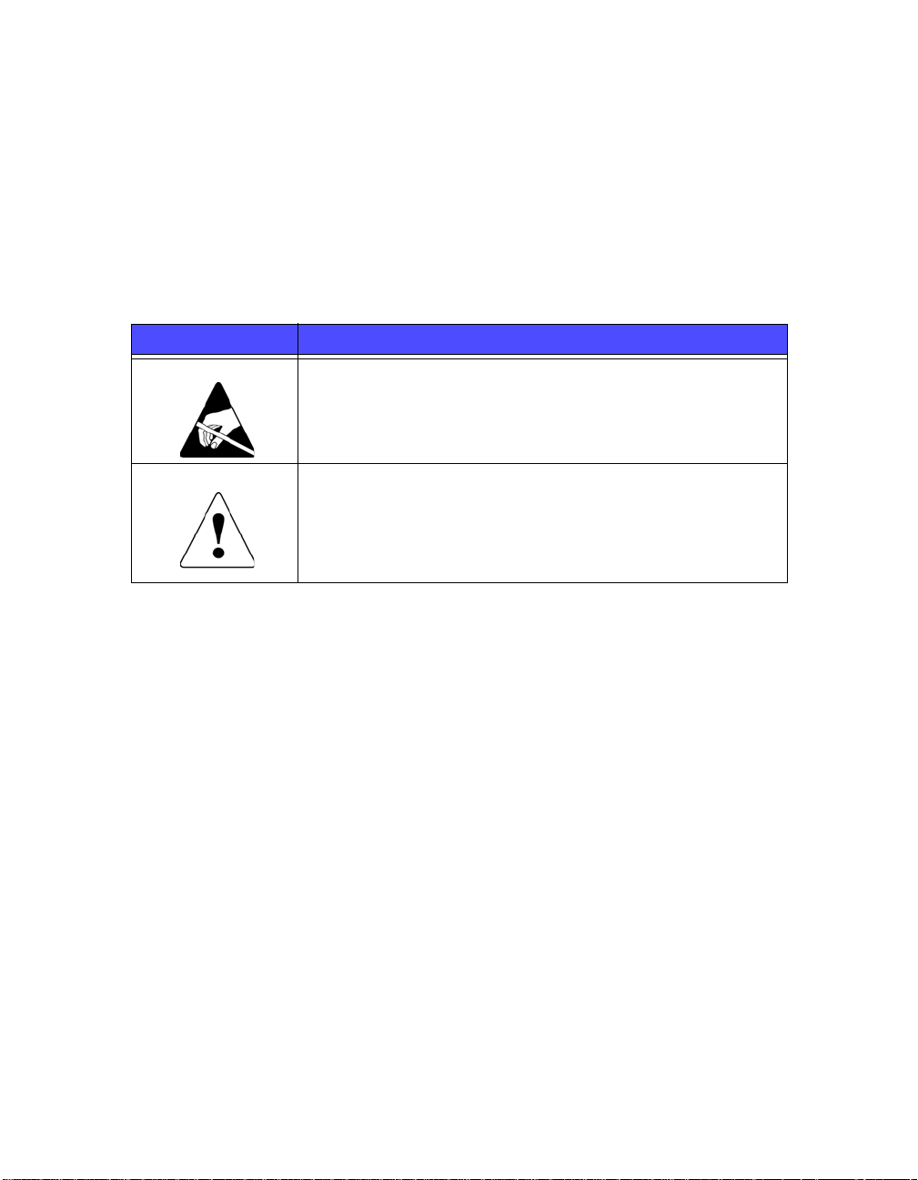
Convention Usage
When displayed, indicates that you must attach an electrostatic
wrist strap to your wrist and a grounded device to prevent
electrostatic discharge.
When displayed, indicates a potential personal injury hazard.
Documentation and Technical Support
For detailed information about PS Series storage arrays, groups, and volumes, see
the following documentation:
• Release Notes. Provides the latest information about PS Series storage arrays.
• QuickStart. Describes how to set up the storage array hardware and create a
PS Series group. Be sure to use the manual for your array model.
• Group Administration. Describes how to use the Group Manager graphical
user interface (GUI) to manage a PS Series group. This manual provides
comprehensive information about product concepts and procedures.
• CLI Reference. Describes how to use the Group Manager command line
interface (CLI) to manage a PS Series group and individual arrays.
• Hardware Maintenance. Provides information about maintaining the storage
array hardware. Be sure to use the manual for your array model.
vi
Page 7

PS3000 Series Hardware Maintenance Preface
• Online help. In the GUI, expand Tools in the far left panel and then click
Online Help for help on both the GUI and the CLI. See Obtaining Online
Help on page 2-16.
The QuickStart and Hardware Maintenance manuals are printed and shipped with
the product. They are also located on the PS Series documentation CD-ROM that
is shipped with the product, along with the Group Administration and CLI
Reference manuals and the Group Manager online help.
®
In addition, the Host Integration Tools for Microsoft
Windows® systems are
available on the Host Integration Tools CD-ROM that is shipped with the product.
Technical support on EqualLogic products is available for customers with arrays
under warranty and customers with a valid support contract. To obtain support:
• Visit the EqualLogic Customer Support website to download the latest
documentation and firmware. Go to
www.equallogic.com and log in to
your support account. If you do not have an account, register for an account.
• From the Customer Support website, you can submit a service request.
• In the United States, call toll-free 877-887-7337. Outside the United States,
call +1 919-767-5729. If the issue is urgent, ask to speak with a member of the
EqualLogic Customer Support team.
Warranty Information
The PS3000 Series array warranty is included in the shipping box. For
information about registering a warranty, visit the EqualLogic website,
www.equallogic.com.
Restricted Access Requirement
PS Series arrays must be installed in a restricted access location. A restricted
access location is an area that is intended only for qualified or trained personnel.
vii
Page 8
PS3000 Series Hardware Maintenance Preface
Regulatory Agency Notices
PS Series arrays have been tested and found to comply with the limits for a Class
A digital device, pursuant to part 15 of the FCC rules and other international
standards. These limits are designed to provide reasonable protection against
harmful interference when the equipment is operated in a commercial
environment.
This equipment generates, uses, and can radiate radio frequency energy and, if not
installed and used in accordance with the instruction manual, may cause harmful
interference to radio communications. Operation of this equipment in a residential
area is likely to cause harmful interference, which the user will be required to
correct at his or her own expense.
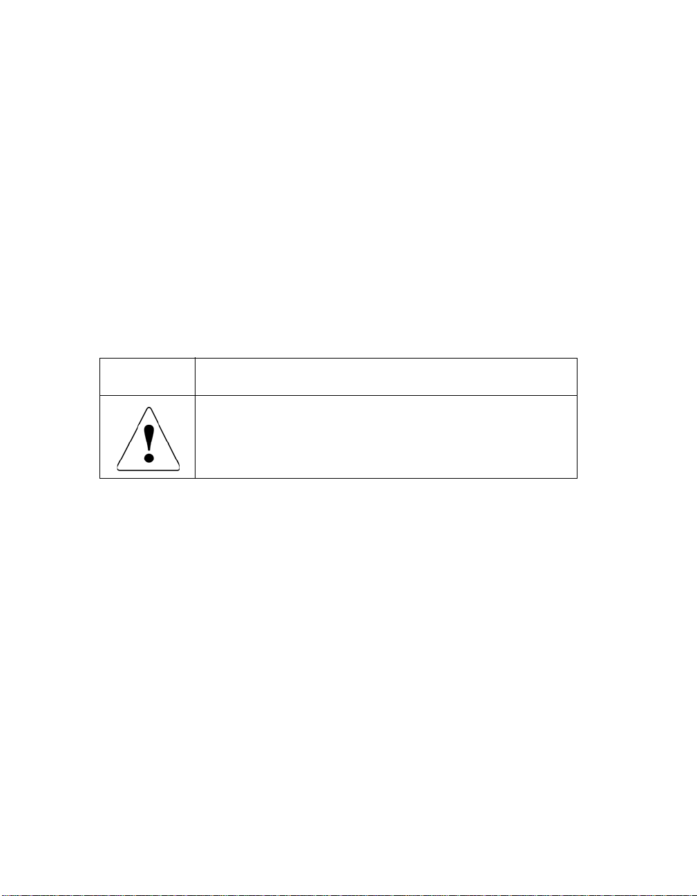
Regulatory Agency Notes
Service Note
Disconnect all PS Series storage array power cables before
servicing to avoid electric shock.
There is a danger of explosion if a PS Series storage array control
module cache battery is incorrectly replaced. Replace a battery only
with the same or equivalent battery, as recommended by the
manufacturer, and use the instructions in this document. Discard
used batteries according to the manufacturer’s instructions.
viii
Page 9
1 Basic Array Information
This chapter includes basic information about PS3000 Series arrays:
• Array Front and Back Panels on page 1-1
• Interpreting Operations Panel LEDs on page 1-2
• Using an Electrostatic Wrist Strap on page 1-4
• Shutting Down and Restarting an Array on page 1-4
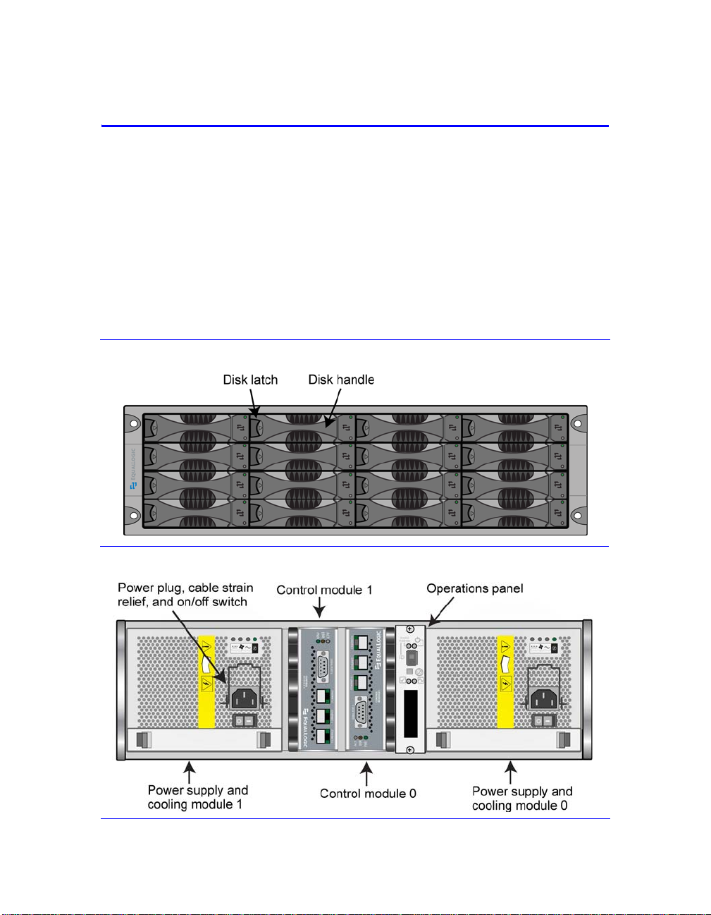
Array Front and Back Panels
The front and back panels of a PS3000 Series array are shown below.
Figure 1-1: PS3000 Series Front Panel
Figure 1-2: PS3000 Series Back Panel
1–1
Page 10
PS3000 Series Hardware Maintenance Basic Array Information
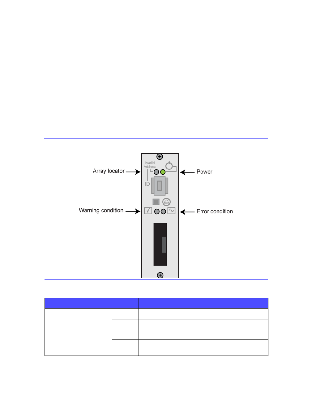
Interpreting Operations Panel LEDs
The operations panel is used to monitor PS3000 Series hardware components. The
panel is not redundant, but an array can continue to operate if it fails. See your PS
Series array service provider for information about servicing the panel.
Figure 1-3 and Table 1-1 describe the LEDs on the PS3000 Series array
operations panel, which can alert you to errors and conditions that require your
attention. Serious problems should be reported to your PS Series service provider.
For information about other LEDs, see Interpreting Disk LEDs on page 2-1,
Interpreting Control Module LEDs on page 3-2, and Interpreting Power Supply
and Cooling Module LEDs on page 4-1.
Figure 1-3: Operations Panel LEDs
Table 1-1: Operations Panel LED Descriptions
Operations LED Color Description
Power (upper right) Off No power.
Green Power.
Array locator (upper left) Off No power or normal condition.
Flashing
orange
1–2
Administrator enabled the array locator function.
Page 11
PS3000 Series Hardware Maintenance Basic Array Information
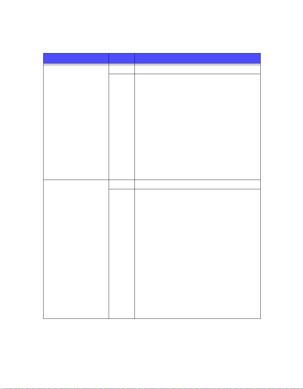
Table 1-1: Operations Panel LED Descriptions (Continued)
Operations LED Color Description
Warning condition
(lower left)
Error condition (lower
right)
Off No power or normal condition.
Flashing
orange
Off No power or normal condition.
Flashing
orange
One or more of the following has occurred:
• RAID set is degraded but still functioning.
• RAID set (volume level) has lost blocks.
• Component temperature is near a limit.
• Fan failed or fan RPMs exceed limit.
• Power supply is not installed or has no power.
• Only one control module installed or control
module has failed over.
• Control module has insufficient RAM.
• Syncing active and secondary control modules.
• No communication between control modules.
• Installed spare disk does not have enough
capacity to replace a disk in a RAID set.
• A non-critical hardware component failed.
• Real-time clock battery is low.
One or more of the following has occurred:
• RAID is not functioning.
• Lost block table is full.
• Temperature exceeds upper or lower limit.
• Control module cache has lost data.
• A cooling module is not installed.
• Both fans on a cooling module have failed.
• Cache battery has less than 72 hours charge or
temperature is too high to charge battery.
• NVRAM coin cell battery failed.
• Cache contains data that does not belong to any
of the installed disks.
• More than one valid RAID set exists in array.
• Control modules are different models.
• A critical hardware component has failed.
• Operations panel failed or not installed.
• Storage enclosure processor that monitors
array components has experienced a failure.
1–3
Page 12
PS3000 Series Hardware Maintenance Basic Array Information
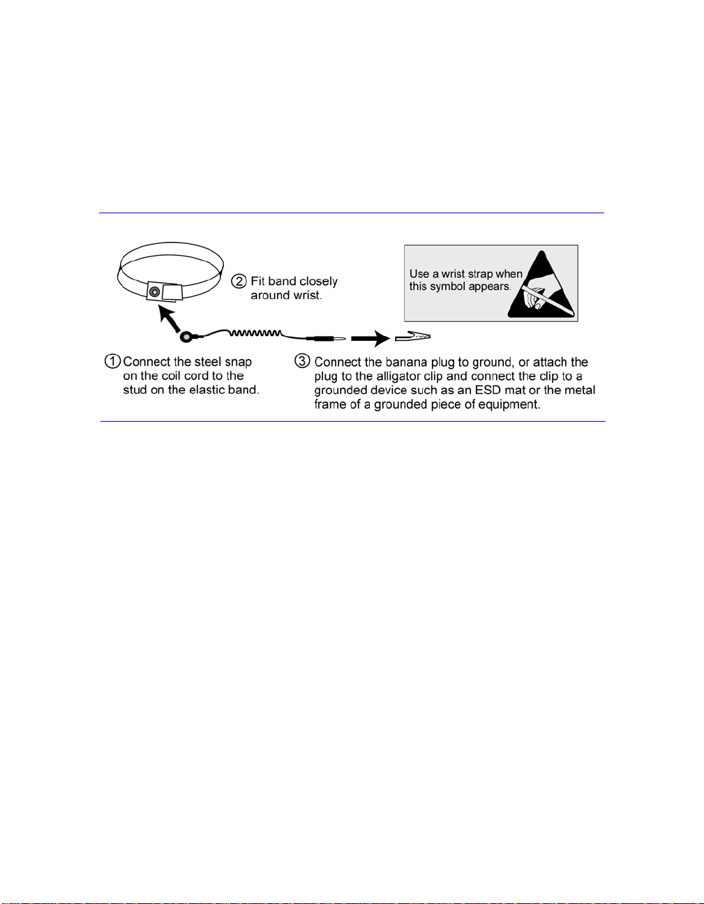
Using an Electrostatic Wrist Strap
When handling the array chassis, disks, or control modules, you must use an
electrostatic protection device to prevent electrostatic discharge.
An electrostatic wrist strap is included in the shipping box.
Figure 1-4: Using an Electrostatic Wrist Strap
Shutting Down and Restarting an Array
A PS3000 Series array includes redundant, hot-swappable disks, power supplies,
and control modules (if a dual control module array). Y ou can remove a redundant
component without affecting operation if a functioning component is available.
Otherwise, it is recommended that you cleanly shut down the array and turn off
power before removing a component.
Note: When an array is shut down, any volumes with data on the array will be set
offline until the array is successfully restarted. This may affect initiators
that are connected to the volumes.
To shut down an array, follow these steps:
1. Do one of the following:
• Use telnet or SSH to connect to a functioning IP address assigned to a
network interface on the array. Do not connect to the group IP address.
• Use the null modem cable shipped with the array to connect Serial Port 0
on the active control module (ACT LED is green) to a console or a
computer running a terminal emulator.
1–4
Page 13

PS3000 Series Hardware Maintenance Basic Array Information
Serial line characteristics are as follows:
- 9600 baud
-One STOP bit
- No parity
- 8 data bits
- No hardware flow control
2. Log in to an account with read-write access, such as the
3. Enter the
Login: grpadmin
Password: xxxxxxx
> shutdown
shutdown command, as shown next.
Welcome to Group Manager
Copyright 2001-2007 EqualLogic, Inc.
grpadmin account.
If you are using a serial connection to shut down an array, it is safe to turn off
power when the “press any key” message appears. (Pressing any key will restart
both control modules.)
If you are using a network connection, the session will be disconnected before the
array is fully shut down. Confirm that the ACT LED on each control module is off
(not lit) before turning off power to the array.
After performing array maintenance, you can turn on power to the array . When the
array restart completes, the member and volumes will be set online.
1–5
Page 14

Page 15

2 Maintaining Disks
Each PS3000 Series array includes up to 16 hot-swappable disks. Disk
maintenance topics include:
• Interpreting Disk LEDs on page 2-1
• Disk Handling Requirements on page 2-2
• Identifying Failed Disks on page 2-3
• Removing Disks on page 2-3
• Installing Disks on page 2-5
Interpreting Disk LEDs
Figure 2-1shows how disks are numbered in a PS3000 Series array.
Figure 2-1: PS3000 Series Disk Numbering
Figure 2-2 shows the disk LEDs. Table 2-1 describes the LEDs.
Figure 2-2: PS3000 Series Disk LEDs
2–1
Page 16

PS3000 Series Hardware Maintenance Maintaining Disks
Table 2-1: PS3000 Series Disk LED Descriptions
Disk LEDs Color Description
Top Off No power or error condition.
Green Power.
Flashing green Disk activity.
Bottom Off No power or normal condition.
Red Error condition.
Disk Handling Requirements
You must adhere to the following disk handling requirements:
• Store disks properly. S tore replacement disks in the packaging in which they
were shipped. Do not stack disks or place anything on top of a disk.
• Protect disks from electrostatic discharge. Wear an electrostatic wrist strap
when handling a disk, unless it is protected from electrostatic discharge.
• Handle disks carefully. Hold a disk only by the plastic part of the carrier or
the handle. Do not drop or jolt a disk or force a disk into a disk slot.
• Warm replacement disks to room temperature before installation. For
example, let a disk sit overnight before installing it in an array.
• Do not leave disk slots empty. Each disk slot in an array must contain a disk
drive assembly or a blank carrier. Operating an array with an empty disk slot
will void your warranty and support contract.
• Do not remove a disk from its carrier. This action will void your warranty
and support contract.
• Keep shipping material. Return a failed disk to your PS Series array service
provider in the packaging in which the replacement disk was shipped.
Shipping disks in unauthorized packaging may void your warranty.
2–2
Page 17

PS3000 Series Hardware Maintenance Maintaining Disks
Identifying Failed Disks
Disks in a PS3000 Series array are numbered from 0 to 15 (from left to right, top
row to bottom row). A disk failure is indicated by:
• The disk’s error LED (bottom) is red, and the power LED (top) is off. See
Interpreting Disk LEDs on page 2-1.
• A message on the console, in the event log, or in the Group Manager GUI
Alarms panel describes a disk failure.
• The GUI Member Disks window or the CLI
command shows a disk failure.
member select show disks
Handling Failed Disks
How an array handles a disk failure depends on whether a spare disk is available
and whether the RAIDset containing the failed disk is degraded. For example:
• If a spare disk is available, it replaces the failed disk. Performance is normal
after reconstruction completes.
• If a spare disk is not available and the failed disk is in a RAIDset with no
previous disk failure, the RAIDset becomes degraded. Performance may be
impaired.
• If a spare disk is not available and the failed disk is in a RAIDset that is
already degraded, data may be lost and must be recovered from a backup.
Removing Disks
Before removing a disk or blank carrier from an array, attach an electrostatic
protection device, as described in Using an Electrostatic Wrist Strap on page 1-4.
Notes: Replace a failed disk as soon as possible to ensure the highest availability .
Do not remove a disk from a slot, unless you have another disk or a blank
carrier to replace it. Each slot must contain a disk or blank carrier.
Do not remove a functioning disk from an array , unless the disk is a spare;
otherwise, a RAIDset may become degraded. If you remove a spare,
replace the disk as soon as possible.
Before completely removing a functioning disk from an array slot, wait
30 seconds to allow the disk to stop spinning and the heads to land.
Store replacement disks in the packaging in which they were shipped.
2–3
Page 18

PS3000 Series Hardware Maintenance Maintaining Disks
Figure 2-3 shows how to remove a disk from a PS3000 Series array. Instructions
for removing a blank carrier are similar, except you do not have to wait 30
seconds.
Figure 2-3: Removing a Disk
2–4
Page 19

PS3000 Series Hardware Maintenance Maintaining Disks
Installing Disks
Before installing a disk or blank carrier in an array, attach an electrostatic
protection device, as described in Using an Electrostatic Wrist Strap on page 1-4.
Notes: Install only disks of the same type, speed, and spin rate in an array. The
color of the handle release button indicates the disk type.
You can use disks with different sizes in an array. However, the smallest
disk in the array will determine how much space can be used on each disk.
For example, if the smallest disk is 400GB, only 400GB of space will be
available for use on each disk.
Be sure to insert a disk fully in the chassis before pushing in the handle.
When correctly installed, the disk carrier should not protrude from the
chassis. After installation, make sure the disk power LED (top) is green or
flashing green.
There is a two-minute delay between the time you insert a disk and the
time the disk is automatically configured into a RAIDset. This time
interval allows multiple disks to be simultaneously configured in an array ,
which is more efficient than installing a single disk, configuring it, and
then repeating the process. For example, when you install a disk, the timer
starts. If no other disks are installed, the disk is configured after a delay of
two minutes. If you install another disk before two minutes have elapsed,
the timer is restarted.
If you install a disk during RAID reconstruction or verification, the new
disk will not be configured until the operation completes.
2–5
Page 20

PS3000 Series Hardware Maintenance Maintaining Disks
Figure 2-4 shows how to install a disk in an array. Use the same instructions for
installing a blank carrier.
Notes: Make sure the disk is oriented in the position shown below, with the
handle release button to the left.
When correctly installed, a disk will be level with the front of the array. If
the disk is protruding from the array, reinstall the disk.
Figure 2-4: Installing a Disk
Verify that the new disk is operational by checking the LEDs on the front panel, as
described in Interpreting Disk LEDs on page 2-1. The top LED should be green or
flashing green, and the bottom LED should be off.
In addition, the GUI Member Disks window and the CLI
disks
command output should show that the new disk is operational.
2–6
member select show
Page 21

3 Maintaining Control Modules
A PS3000 Series array includes one or two hot-swappable control modules. Each
control module includes a field-replaceable compact flash card (running PS Series
firmware), in addition to cache and NVRAM batteries. For information about
replacing a cache or NVRAM battery, contact your PS Series service provider.
Control module maintenance topics include:
• Supported Control Modules on page 3-1
• Control Module Handling Requirements on page 3-3
• Identifying Control Module Failures on page 3-3
• Understanding Failover Behavior on page 3-3
• Maintaining Control Module Firmware on page 3-4
• Connecting Network Cables on page 3-5
• Removing a Control Module on page 3-7
• Installing a Control Module on page 3-9
• Replacing the Compact Flash Card on page 3-11
Supported Control Modules
At the time of this release, PS3000 arrays support both Type 3 and Type 4 control
modules, which are functionally equivalent and distinguished only by color.
Always check the latest Release Notes for information about additional supported
control modules.
This manual shows arrays with T ype 4 control modules (gray), but the informatio n
also applies to arrays with Type 3 control modules (blue). However, do not mix
control module types in an array.
Figure 3-1: Type 3 Control Module (Blue)
Figure 3-2: Type 4 Control Module (Gray)
3–1
Page 22

PS3000 Series Hardware Maintenance Maintaining Control Modules
Interpreting Control Module LEDs
Control modules have LEDs that enable you to determine the status of the control
module (active or secondary) and identify problems. In addition, each network
interface on a control module also has LEDs.
Figure 3-3: Control Module LEDs
Note: Control modules are installed vertically in a PS3000 Series array, with the
latch mechanism facing the power supply and cooling module.
Table 3-1: Control Module LED Descriptions
Control Module LEDs Color Description
ACT Off No power, secondary control module is not
synchronized with active control module, or
error condition.
Green Active control module (serving network I/O).
Orange Secondary control module; cache is
synchronized with active control module.
ERR Off No power or no error condition.
Red Array is starting up or error condition.
PWR Off No power.
Green Power.
Table 3-2: Network Interface LED Descriptions
Network Interface LEDs Color Description
Left (as shown in
Figure 3-3)
Right (as shown in
Figure 3-3)
3–2
Off
Green Connected to network.
Off No power or not transmitting.
Green Transmitting.
No power or not connected to network.
Page 23

PS3000 Series Hardware Maintenance Maintaining Control Modules
Control Module Handling Requirements
You must adhere to the following control module handling requirements:
• Protect control modules from electrostatic discharge. Always wear an
electrostatic wrist strap when handling a control module, as described in
Using an Electrostatic Wrist Strap on page 1-4. When not installed, store a
control module in an antistatic bag or place it on a surface protected from
electrostatic discharge.
• Do not remove a control module from an array while the contro l modules
are synchronizing. When synchronization completes, a console message will
appear. Also, the ACT LED on the secondary control module will be orange.
• Do not leave a control module slot empty. In an array with one control
module, always attach a blank face plate to the empty control module slot.
Identifying Control Module Failures
A failure in a control module can be indicated by the following:
• A control module’s ERR LED is red or the PWR LED is off but there is
power to the array. See Interpreting Control Module LEDs on page 3-2.
• The ACT LED on one control module is green, but the ACT LED on the other
control module is off instead of orange.
• A message on the console, in the event log, or in the Group Manager GUI
Alarms panel describes a control module failure.
• The GUI Member Controllers window or CLI
controllers
CM0 refers to the control module to the right, when viewing the array back panel.
CM1 refers to the control module to the left.
command shows the control module as not installed.
member select show
Understanding Failover Behavior
A PS3000 Series array can have one to three active network connections. In a dual
control module array, only one control module is active (serving network traffic)
at one time. Each control module includes a battery-backed write cache for storing
recently-used data. For redundancy, the cache on the secondary control module
mirrors the data that is stored in the cache on the active control module.
Each control module has three ports: Ethernet 0, Ethernet 1, and Ethernet 2. The
active control module can use a network interface only if there is a cable
3–3
Page 24

PS3000 Series Hardware Maintenance Maintaining Control Modules
connected to the port on the active control module. Therefore, you should connect
a cable to the network interface port on each control module to ensure that both
control modules can access an interface.
A PS3000 Series array provides two types of network failure protection:
• Network connection failover. If multiple network interfaces are configured
and one network interface fails, iSCSI initiators that were connected to the
failed interface can reconnect to the group IP address and be redirected to a
functioning interface. For example, in a single control module array, if
Ethernet 0 and Ethernet 1 are connected to a network, and Ethernet 0 fails,
initiators that were connected to Ethernet 0 can be redirected to Ethernet 1.
• Control module failover. In a dual control module array, if the active control
module fails, the secondary automatically takes over and becomes active. If a
cable is connected to the port on the newly active control module, network I/O
can continue through that interface. Control module failover is transparent to
applications, but iSCSI initiators must reconnect to the group IP address.
Maintaining Control Module Firmware
A PS3000 Series array includes one or two control modules, each with a compact
flash card running the array firmware. You should run the latest firmware version
to take advantage of new product features and enhancements.
Caution: In a dual control module array, both control modules must be running
the same firmware version; otherwise, only one control module will be
functional. When you use the
update command procedure, both
control modules are updated to the same firmware version.
Group members should run the same firmware version; otherwise, only
functionality common to all versions will be available in the group. See the
PS Series Release Notes for information about mixed-firmware groups.
If you are upgrading to a dual control module array or replacing a failed compact
flash card, be sure to order the correct firmware version from EqualLogic. If you
are replacing a failed control module, remove the compact flash card from the
failed control module and install it in the replacement control module. This will
ensure that you retain the correct firmware.
A new compact flash card will show the firmware version on the label. To display
the firmware version running on an array, examine the GUI Member Controllers
window or use the CLI
member select show controllers command. If the
firmware on a compact flash card does not match the firmware running on an
array, do not install it. Instead, contact your PS Series array service provider.
3–4
Page 25

PS3000 Series Hardware Maintenance Maintaining Control Modules
Connecting Network Cables
A PS3000 Series array must have at least one and can have up to three active
network connections at one time. Multiple network connections are recommended
for performance and availability.
Connect cables to network interfaces as follows:
• For copper-based networks, use Category 5E or Category 6 cables with RJ45
connectors. Use Category 5 cables if they meet the TIA/EIA TSB95 standard.
• Connect interfaces in this order: Ethernet 0, Ethernet 1, and Ethernet 2.
• Connect interfaces to different network switches.
• In a dual control module array, to ensure connectivity if a control module
fails, connect a cable to the interface port on each control module. For
example, connect a cable to Ethernet 0 on CM0 and Ethernet 0 on CM1.
See the PS Series QuickStart and the Technical Report on the EqualLogic
Customer Support website for network requirements and recommendations.
For a single control module array, the minimum network configuration is one
network connection to Ethernet 0. However, the single network connection is a
potential point of failure. Therefore, it is recommended that you connect multiple
network interfaces to different network switches.
For example, if you connect cables as shown in Figure 3-4, and Ethernet 0 fails,
initiators can be redirected to another functioning interface. This configuration
provides the maximum network bandwidth.
Figure 3-4: Recommended Single Control Module Configuration
3–5
Page 26

PS3000 Series Hardware Maintenance Maintaining Control Modules
For a dual control module array, the minimum network configuration is a network
connection to Ethernet 0 on both control modules. Although this configuration
protects against control module failover, it is still a potential point of failure (for
example, if the network cable connected to the active control module is
disconnected). Therefore, it is recommended that you connect multiple network
interfaces to different switches.
Figure 3-5 shows the minimum network configuration for a dual control module
PS3000 Series array. Cables are connected to Ethernet 0 on both control modules.
Figure 3-5: Minimum Dual Control Module Configuration
Figure 3-6 shows the recommended network configuration for a dual control
module PS3000 Series array. This configuration provides the highest network
availability and the maximum network bandwidth.
3–6
Page 27

PS3000 Series Hardware Maintenance Maintaining Control Modules
Figure 3-6: Recommended Dual Control Module Configuration
Removing a Control Module
If a control module fails, you should remove it and replace it with a functioning
control module. You also ma y need to temporarily remove a control module to
replace a compact flash card.
In a dual control module PS3000 Series array, you can remove a contro l module
without shutting down the array, if the remaining control module has at least one
connected and functioning network interface. However, if you remove the active
control module (the LED labeled ACT will be green), there will be a short
interruption as failover to the secondary control module occurs.
Caution: Do not remove a control module from an array while the control
modules are still synchronizing. A message will appear on the console
when synchronization completes. The ACT LED on the secondary
control module will be orange when synchronization completes.
Before removing a control module:
• If you have a single control module array, if possible, cleanly shut down the
array before removing the control module to protect against cache data loss.
See Shutting Down and Restarting an Array on page 1-4.
• Disconnect any serial or network cables attached to the control module. If you
have a dual control module array, you may want to re-attach the network
cables to the functioning control module to ensure uninterrupted data access.
• Attach an electrostatic wrist strap, as described in Using an Electrostatic W rist
Strap on page 1-4.
3–7
Page 28

PS3000 Series Hardware Maintenance Maintaining Control Modules
To remove a control module, follow the instructions in Figure 3-7.
Note: If you are removing a failed control module, you must remove the compact
flash card from the failed control module, as described in Replacing the
Compact Flash Card on page 3-11. Then, install the card in the
replacement control module. This will ensure that the new control module
is running the correct firmware.
Figure 3-7: Removing a Control Module
Once you remove a control module, place it on a surface that is protected from
electrostatic charge.
3–8
Page 29

PS3000 Series Hardware Maintenance Maintaining Control Modules
If the array will permanently operate with only one control module, you must
install a blank control module in the empty slot. You can order a blank from your
PS Series array service provider. For proper cooling, do not leave a control
module slot empty.
Installing a Control Module
You may need to install a control module as part of an upgrade from a single
control module array to a dual control module array or for control module
maintenance, such as replacing a failed control module.
Notes: You can upgrade to a dual control module array without shutting down the
array.
Only install control modules of the same type in a PS3000 Series array.
Do not mix control module types in an array.
Before removing a control module:
• Make sure the firmware on the control module’s compact flash card matches
the firmware running on the already-installed control module. See
Maintaining Control Module Firmware on page 3-4.
If you are replacing a failed control module, be sure to remove the compact
flash card from the failed control module and install it in the replacement
control module. This will ensure that the new control module is running the
correct firmware.
• If you are upgrading to a dual control module array, remove the blank control
module from the slot. See the instructions in Figure 3-7 for opening the latch.
• Attach an electrostatic wrist strap (see Using an Electrostatic Wrist Strap on
page 1-4).
To install a control module, refer to the instructions in Figure 3-8.
3–9
Page 30

PS3000 Series Hardware Maintenance Maintaining Control Modules
Figure 3-8: Installing a Control Module
After installing a control module, connect network cables to the control module,
as described in Connecting Network Cables on page 3-5. Then, if the array was
shut down, turn on power to the array.
Check the LEDs, as described in Interpreting Control Module LEDs on page 3-2.
Also, check the GUI Member Controllers window or invoke the CLI
select show controllers
active (if there is only one control module) or secondary.
either
command. The control module status will be
member
If two control modules are installed but only one appears in the GUI or CLI, the
control module may not be properly installed. Re-seat the control module. If both
control modules still do not appear in the GUI or CLI, they may not be running the
same firmware, and you should contact your PS Series array service provider.
3–10
Page 31

PS3000 Series Hardware Maintenance Maintaining Control Modules
Note: Once connected, a control module cache battery may begin to charge. If
you have a dual control module array and the low-battery-safe cache
policy is enabled (the default), the array will operate in write-through
mode until the cache battery is fully charged.
However, if you need optimal performance before the battery is fully
charged, once the battery status is
good/charging, you can temporarily
disable the low-battery-safe policy and force the array to operate in writeback mode. Be sure to re-enable the low-battery-safe policy when the
battery is fully charged. See the Group Administration manual for
information about cache policies.
Replacing the Compact Flash Card
Each control module includes a compact flash card running the PS Series array
firmware. There are two reasons why you may need to replace a compact flash
card:
• The compact flash card fails on an otherwise functioning control module. Be
sure to order a replacement card with the same firmware version as the failed
card. See Maintaining Control Module Firmwar e on pag e 3-4 for information
about identifying firmware.
• The control module fails, but the compact flash card is still functioning. If this
occurs, remove the compact flash card from the failed control module and
install the card in the replacement control module. This will ensure that the
new control module is running the correct firmware.
To access the compact flash card, you can remove a control module in a dual
control module array without shutting down the array, if the remaining control
module has at least one connected and functioning network interface. If you
remove the active control module (the LED labeled ACT will be green), there will
be a short interruption as failover to the secondary control module occurs.
Before replacing a compact flash card:
• If you have a single control module array, if possible, cleanly shut down the
array before removing the control module. See Shutting Down and Restarting
an Array on page 1-4.
• Attach an electrostatic wrist strap, as described in Using an Electrostatic W rist
Strap on page 1-4.
•See Removing a Control Module on page 3-7 for instructions on removing a
control module.
3–11
Page 32

PS3000 Series Hardware Maintenance Maintaining Control Modules
• You can access the compact flash card by sliding the control module partially
from the slot. If you completely remove the control module, place it on a
surface that is protected from electrostatic discharge.
Figure 3-9 on page 3-12 shows how to remove a compac t flash card from a
control module and also how to install a card.
After you replace the compact flash card, see Installing a Control Module on
page 3-9 for instructions on installing a control module.
Figure 3-9: Removing and Installing a Compact Flash Card
After installing the control module, if the array was shut down, turn on power.
To ensure that the control module is operational, check the LEDs, as described in
Interpreting Control Module LEDs on page 3-2. Also, check the GUI Member
Controllers window or invoke the CLI
command. The control module status will be either
3–12
member select show controllers
active or secondary.
Page 33

4 Maintaining Power Supply and Cooling Modules
A PS3000 Series array includes two hot-swappable, combination power supply
and cooling modules.
Maintenance topics include:
• Interpreting Power Supply and Cooling Module LEDs on page 4-1
• Identifying Power Supply and Cooling Module Failures on page 4-2
• Removing a Power Supply and Cooling Module on page 4-2
• Installing a Power Supply and Cooling Module on page 4-4
Interpreting Power Supply and Cooling Module LEDs
Use the power supply and cooling module LEDs, shown in Figure 4-1and
described in Table 4-1, to determine the module status and identify problems.
Figure 4-1: Power Supply and Cooling Module LEDs
Table 4-1: Power Supply and Cooling Module LED Descriptions
Power Supply and
Cooling Module LED
_ _ _
____
~
Color Description
Off No power or normal condition.
Orange DC power failure.
Off No power or normal condition.
Orange Fan failure.
Off No power or normal condition.
Orange AC power failure.
Off No power.
Green Normal array operation.
4–1
Page 34

PS3000 Series Hardware Maintenance Maintaining Power Supply/Cooling Modules
Identifying Power Supply and Cooling Module Failures
A failure on a power supply and cooling module can be indicated by the
following:
• A power supply and cooling module LED is orange. See Interpreting Power
Supply and Cooling Module LEDs on page 4-1.
• Message on the console, in the event log, or in the Group Manager GUI
Alarms panel describes a power supply and cooling module failure.
• GUI Member Enclosure window or the CLI
enclosure
Power supply and cooling module 0 refers to the module on the right side of the
array back panel (when facing the back of the array). Power supply and cooling
module 1 refers to the module on the left side. See Figure 1-2 on page 1-1 for
details.
command shows a power supply and cooling module failure.
member select show
Removing a Power Supply and Cooling Module
If a power supply and cooling module fails, you must replace the module as soon
as possible, although an array can operate with only one working module. To
ensure proper cooling, do not remove a failed module until you are ready to
replace it.
You can remove a power supply and cooling module from an array without
affecting array operation if the second module is installed and functioning.
Otherwise, if possible, cleanly shut down the array before removing the module,
as described in Shutting Down and Restarting an Array on page 1-4.
Caution: After installing a power supply and cooling module, wait until the new
module initializes before removing the other module. New module
initialization can take from one to ten seconds. Completion is indicated
by the green power LED and event log messages stating that fans have
returned to their normal speed.
Figure 4-2 shows how to remove a power supply and cooling module from an
array.
4–2
Page 35

PS3000 Series Hardware Maintenance Maintaining Power Supply/Cooling Modules
Figure 4-2: Removing a Power Supply and Cooling Module
4–3
Page 36

PS3000 Series Hardware Maintenance Maintaining Power Supply/Cooling Modules
Installing a Power Supply and Cooling Module
To install a power supply and cooling module in an array, refer to Figure 4-3.
Figure 4-3: Installing a Power Supply and Cooling Module
If your PS Series array was shipped with a power cable, use this cable to meet
safety requirements.
Be sure to use the cable strain relief to secure the power cable to the array, as
shown in Figure 4-4.
4–4
Page 37

PS3000 Series Hardware Maintenance Maintaining Power Supply/Cooling Modules
Figure 4-4: Using the Cable Strain Relief
Turn on power to the power supply and cooling module (press –). Initialization
generally can take from one to ten seconds. Completion is indicated by the green
power LED and event log messages stating that fans have returned to their normal
speed.
To ensure that the new module is operational, check that there are no red LEDs.
Also, check the GUI Member Enclosure window or invoke the CLI
select show enclosure
command.
member
4–5
Page 38

Page 39

A Environmental, Power, and Other Specifications
Table A-2 describes the environmental, power, and physical specifications for a
PS3000 Series array.
Table A-2: PS3000 Series Array Specifications
Component Requirement
Weight of fully-loaded array 77.6 pounds or 35 kilograms
Operating temperature 41 to 95 degrees F / 5 to 35 degrees C
Storage temperature -22 to 140 degrees F / -30 to 60 degrees C
Maximum operating altitude 10,000 feet (3048 meters)
Operational relative humidity 20 to 80% non-condensing
Thermal output (fully-loaded array) 1700 BTU/hour
Operational shock 5 G for 10 ms 1/2 sin
Operational vibration Random 0.21grms 5 - 500 Hz
Input voltage 100 to 240 VAC (auto-sensing)
Input frequency 48 - 62 Hz
System input power 530 VA (maximum)
Power supplies Dual, 450 watts DC output
Maximum input power: 0.7 KVA
Input current: 7 – 3.5A
Height/Width/Depth 5.12” x 19” x 21.7” (13 x 48.26 x 55.1 cm)
A–1
Page 40

Page 41

Index
A
array
back panel
batteries 3-1
control module restriction 3-9
control modules 3-1
cooling 4-1
disks 2-1
environmental requirements A-1
failure indications 1-2
fans 4-1
firmware 3-4
front panel 1-1
LEDs 1-2, 2-1, 3-2, 4-1
maximum network availability 3-6
maximum network bandwidth 3-5,
1-1
3-6
power supplies 4-1
protecting from discharge 1-4
shutdown procedure 1-4
specifications A-1
B
batteries
charging
servicing 3-1
3-11
C
cable strain relief, using 4-5
cables (network), connecting 3-5
cables (power), connecting 4-4
cables (serial), connecting 1-4
compact flash card
firmware requirements
identifying firmware 3-4
moving 3-8, 3-9, 3-11
replacing 3-4, 3-11
control modules
3-4
batteries
charging cache battery 3-11
checking proper installation 3-10
compact flash card moving 3-8,
3-1
3-9, 3-11
compact flash card replacement
3-4, 3-11
failover behavior 3-3
failure indications 3-3
firmware identification 3-4
firmware requirements 3-4, 3-9,
3-11
handling requirements 3-3
installing in array 3-9
LEDs 3-2
locating 3-3
removing from array 3-7
restriction on mixing 3-9
synchronizing 3-3
types 3-9
verifying operational status 3-10
cooling
indications of failure
initialization 4-2
installing module in array 4-4
LEDs 4-1
locating modules 4-2
removing module from array 4-2
verifying operational status 4-5
4-2
D
disks
failure behavior
failure indications 2-3
handling requirements 2-2
installing in array 2-6
LEDs 2-1
locating 2-3
protecting 2-2
2-3
Index-1
Page 42

PS3000 Series Hardware Maintenance Index
removing from array 2-3
verifying operational status 2-6
E
electrostatic protection, using 1-4
environmental requirements A-1
F
failover
control module
network connection 3-4
port 3-4
failure indications
1-2
array
control modules 3-3
cooling 4-2
disks 2-3
power 4-2
fans
failure indications
initialization 4-2
installing module in array 4-4
LEDs 4-1
locating modules 4-2
maintaining 4-1
removing module from array 4-2
verifying operational status 4-5
firmware
identifying
requirements 3-4, 3-11
3-3, 3-4
4-2
3-4
L
LEDs
control module
cooling modules 4-1
disks 2-1
network interfaces 3-2
operations panel 1-2
power supplies 4-1
3-2
N
network
cable connections
configuration examples 3-5
failure protection 3-4
increasing availability 3-5
increasing performance 3-5
maximum availability 3-6
maximum bandwidth 3-5, 3-6
recommendations 3-5
requirements 3-5
network interfaces, LEDs 3-2
3-5
O
operations panel
1-2
LEDs
servicing 1-2
P
physical requirements A-1
power cables
restriction
using strain relief 4-4
power supplies
cable strain relief
indications of failure 4-2
initialization 4-2
installing module in array 4-4
LEDs 4-1
locating modules 4-2
maintaining 4-1
removing module from array 4-2
verifying operational status 4-5
4-4
4-5
R
requirements
array handling
control modules 3-3
cooling 4-2
disks 2-2
environmental A-1
firmware 3-4
network 3-5
physical A-1
1-4
Index-2
Page 43

PS3000 Series Hardware Maintenance Index
power 4-2
power cables 4-4
S
serial connection, making 1-4
shutting down an array 1-4
specifications, array A-1
U
upgrading to dual control modules 3-4
Index-3
Page 44

Page 45

Page 46

 Loading...