

Page 1

Dell EqualLogic FS7610 Series Appliances
Hardware Owner's Manual
Page 2

© Copyright 2011–2013 Dell Inc. All rights reserved.
Dell™ and EqualLogic® are trademarks of Dell Inc.
All trademarks and registered trademarks mentioned herein are the property of their respective owners.
Information in this document is subject to change without notice.
Reproduction in any manner whatsoever without the written permission of Dell is strictly forbidden.
Published: October 2013
Part Number: 110-6179-EN-R1
Page 3

Table of Contents
Preface
1 Basic Appliance Information
Appliance Components
Connecting an Appliance to Power
Turning Power On and Off
Required Tools
Technical Specifications
2 Replacing Components
Safety Recommendations
Required Tools
Using an Electrostatic Wrist Strap
Replacing a Controller
Installing a Controller
Replacing SFP+ Transceivers
Replacing a Power Supply
Replacing a Cooling Fan
Replacing the Appliance
Returning Failed Hardware
3 What to Do Next
Appendix A: NOM Information (Mexico Only)
Glossary
v
1
1
4
5
6
6
9
9
9
9
10
11
12
13
16
18
18
19
21
23
iii
Page 4

Dell EqualLogic FS7610 Hardware Owner's Manual
iv
Page 5

Preface
Dell™ EqualLogic® FS Series appliances, coupled with PS Series arrays, offer a high-performance, highavailability, scalable NAS solution. This manual describes how to maintain and troubleshoot the customerreplaceable components of the EqualLogic FS7610 appliance.
Audience
The information in this guide is intended for hardware administrators responsible for maintaining EqualLogic
FS7610 hardware.
Related Documentation
For detailed information about FS Series appliances, PS Series arrays, groups, volumes, array software, and host
software, log in to the Documentation page at the customer support site.
Dell Online Services
You can learn about Dell products and services with this procedure:
1. Visit dell.com or the URL specified in any Dell product information.
2. Use the locale menu or click on the link that specifies your country or region.
Dell EqualLogic Storage Solutions
To learn more about Dell EqualLogic products and new releases, visit the Dell EqualLogic Tech Center site:
delltechcenter.com/page/EqualLogic. Here you can also see articles, demos, online discussions, and more details
about the benefits of our product family.
Technical Support and Customer Service
Dell support service is available to answer your questions about PS Series SAN arrays and FS Series appliances.
Contacting Dell
If you are a customer in the United States or Canada in need of technical support, call 1-800-945-3355. If you
are outside of the United States or Canada, visit support.dell.com/support/topics/global.aspx.
If you have an Express Service Code, have it ready. The code helps the Dell automated support telephone
system direct your call more efficiently.
Warranty Information
The FS7610 appliance warranty is included in the shipping box. For information about registering a warranty,
visit eqlsupport.dell.com/utility/form.aspx?source=warranty.
v
Page 6
Dell EqualLogic FS7610 Hardware Owner's Manual Preface
Note, Caution, and Warning Symbols
A NOTE symbol indicates important information that helps you make better use of your hardware or
software.
A CAUTION symbol indicates potential damage to hardware or loss of data if instructions are not
followed.
A WARNING symbol indicates a potential for property damage, personal injury, or death.
vi
Page 7
1 Basic Appliance Information
This chapter contains information about the location and basic operation of the components in a Dell™
EqualLogic® FS7610 NAS appliance. The chapter also includes general operating procedures such as power
ON and power OFF operations, and how to return failed components.
Appliance Components
The only customer-replaceable components in the appliance are the bezel and the fans, on the front of the
appliance, and the controllers and power supplies, on the back of the appliance.
Appliance Front-Panel Features
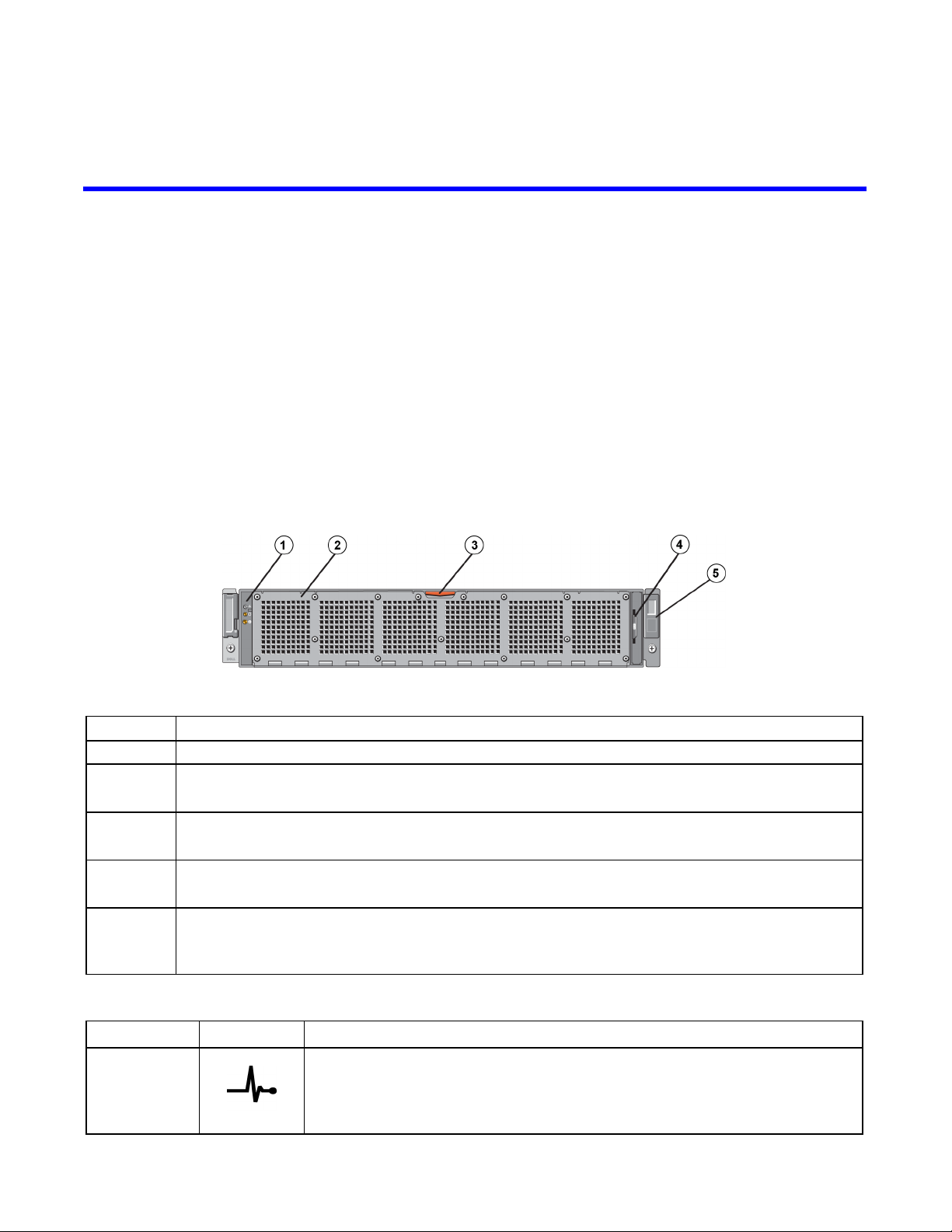
Figure 1 and Figure 2 show the front panel of the FS7610 NAS appliance. Table 1 lists the front-panel LED
descriptions.
Figure 1: FS7610 Front Panel (Bezel Off, Cover Closed)
Table 1: FS7610 Front-Panel Components
Number Component
1 System health indicator, power, and system identification LEDs (see Table 2 for details)
2
3
4
5
LED Indicator Icon State and Description
System Health
Indicator
Cooling fan access door
Encloses and protects the six hot-swappable cooling fans.
Cooling fan access door release latch
Press the access door release latch to expose the hot-swappable cooling fans.
Information tag
A slide-out label panel listing the system NIC and BMC MAC addresses for both controllers
Service tag
Displays the appliance service tag information (identical to the service tag information on the
back panel). You might be asked for this information when you call technical support.
Table 2: Front-Panel LED Descriptions
The system status LED lights only when the system power is on:
Solid blue—Normal operation.
Blinking amber—One of the controllers is reporting hardware errors, battery
errors, or a controller is missing.
1
Page 8
Dell EqualLogic FS7610 Hardware Owner's Manual 1 Basic Appliance Information
LED Indicator Icon State and Description
Power-On
Indicator
System
Identification
Button
The power LED lights green when at least one power supply is connected to a
power source and is supplying power to the system.
Identification buttons on the front and back panels locate a particular system
within a rack. Press the front identification button and the system status
indicator on the back flashes until either button is pressed again.
Blinking blue—Identification on.
Solid blue—Identification off.
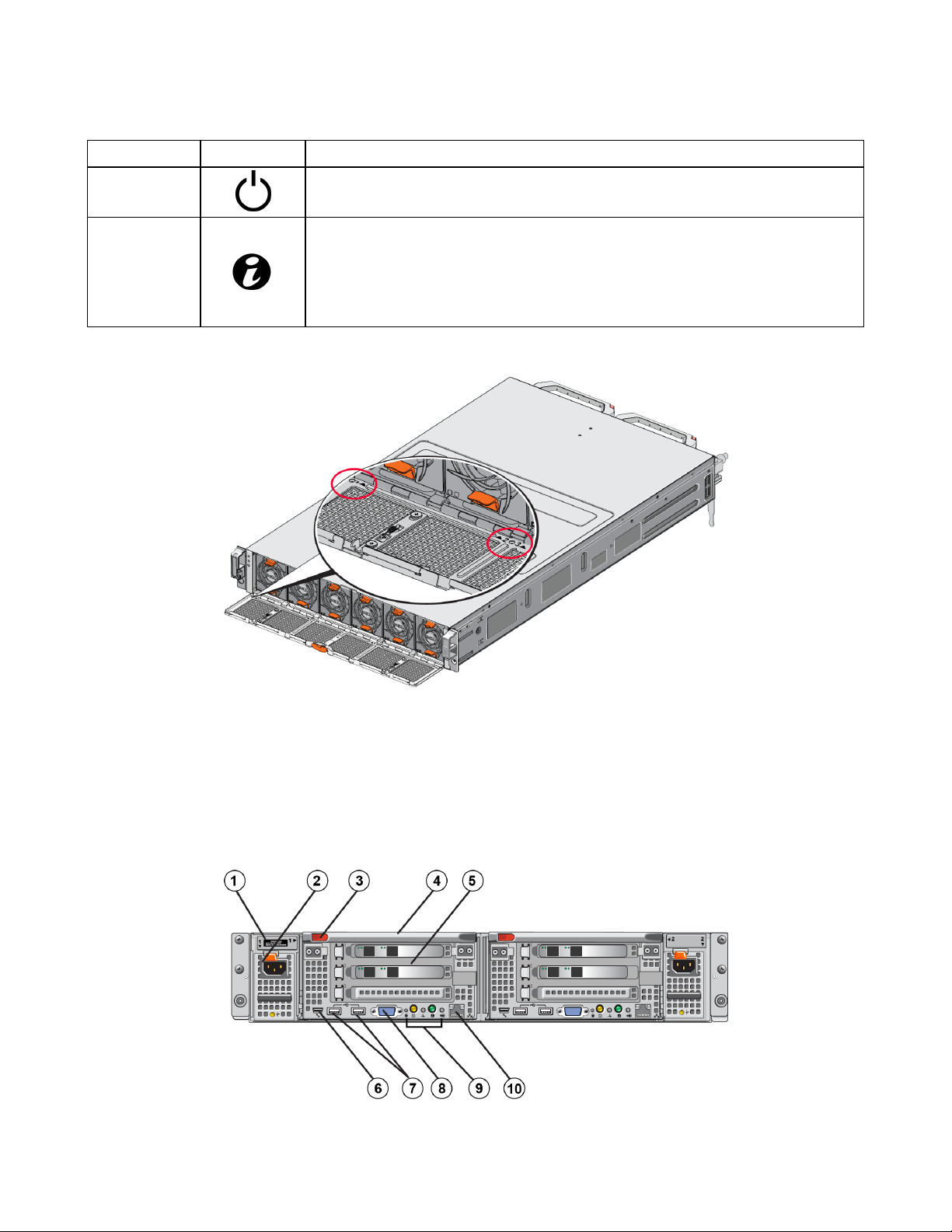
Figure 2: FS7610 Front Panel (Cover Open)
The fans are numbered 1 through 6, from left to right.
Appliance Back-Panel Features
Figure 3 and Table 3 describe the back panel of the FS7610 NAS appliance. Table 4 describes the LEDs for
each controller.
Figure 3: FS7610 Back Panel
2
Page 9
Dell EqualLogic FS7610 Hardware Owner's Manual 1 Basic Appliance Information
Table 3: FS7610 Back-Panel Components
Number Component
Service tag
1
Displays the appliance service tag information (identical to the service tag information on the front
panel).
2
Power supply (one of two)
Left: PSU1 Right: PSU2
3 Controller release latch
4 Controller handle
5
Controller (one of two); redundant NAS processing unit, each containing a backup power supply (BPS)
Left: Controller 1 Right: Controller 2
Serial COM port (mini USB connector).
6
Allows you to connect a serial device to the system.
This connector is for service only. Use this connector only if asked to do so by Dell support.
7 USB port
8 Video port
9
10
From left to right: Service Action Button, Power-On Indicator/Power Button, Controller Health
Indicator, System Identification Button, and Cache Active/Off-Load LED (see Table 4).
Remote KVM
LED Indicator/
Button
Service Action
Button
Controller State
Indicator/Power-On
Button
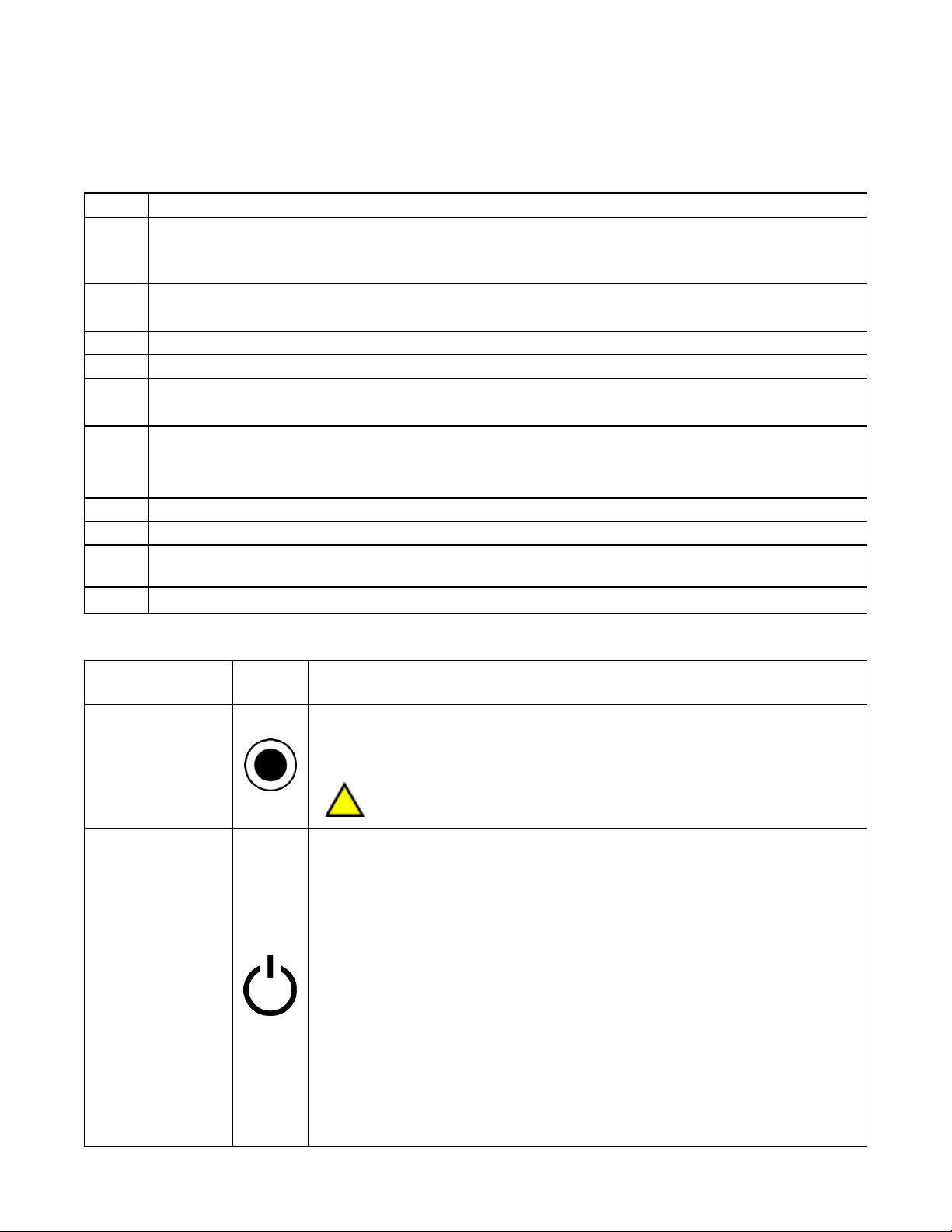
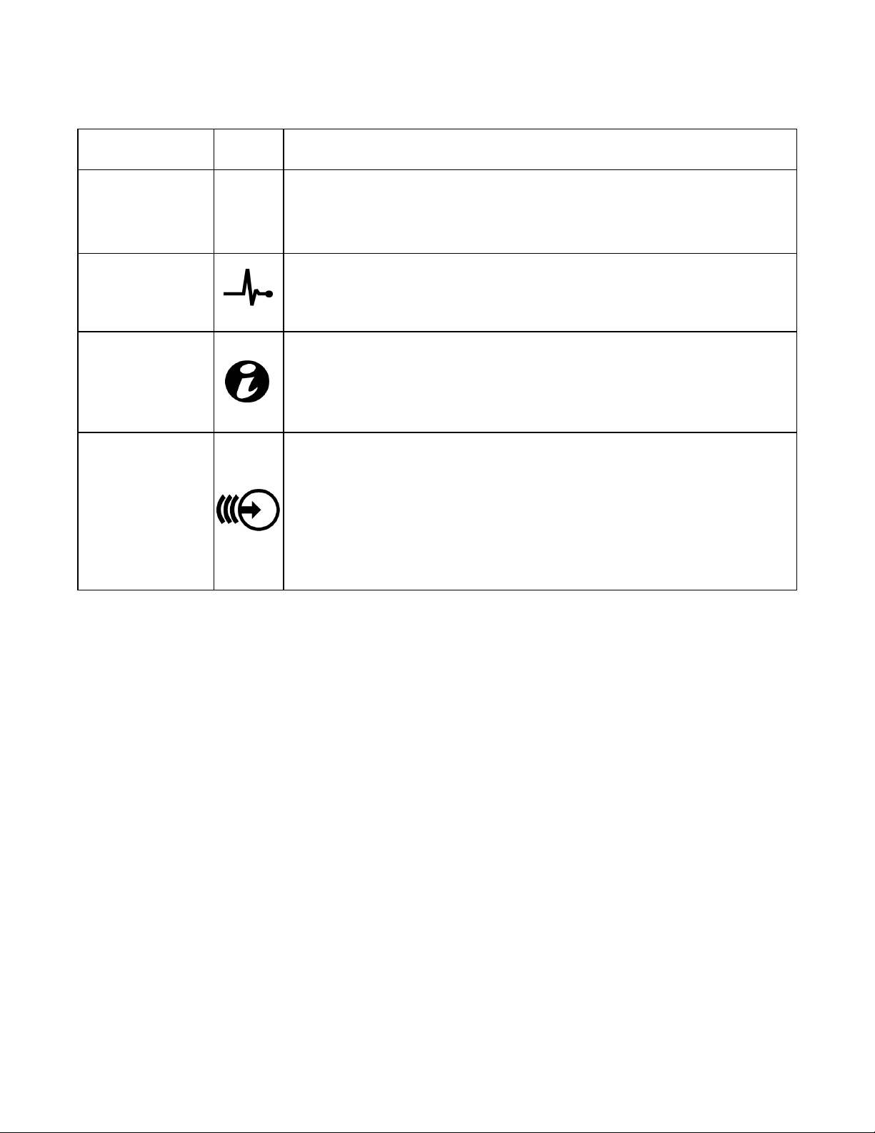
Table 4: Controller LED States and Descriptions
Icon State and Description
Used for troubleshooting certain errors; press using the end of a paper clip.
Press and hold the button for 10 seconds to generate an SCI (System Control
Interrupt).
Use this button only if directed by qualified support personnel or after
consulting the operating system's documentation.
Controls the power supply to the appliance and indicates its state:
• When the controller is ON, press and release to shut down.
• When the controller is OFF, press and release to power the controller on.
Solid amber—The controller is ON and about to enter system power-on selftest (POST). If the controller is ON but is not responding, the controller might
have a hardware failure that is not allowing it to start the BIOS POST.
Slowly blinking (flashes once every two seconds) amber—The controller is
currently in BIOS POST or option ROM load stage. If the controller is not
responding, it might indicate that a failure has occurred in either POST or
option ROM load phase.
Slowly blinking green (flashes once every two seconds)—The controller is
attempting to start the operating system. If the controller is not responding, slow
blinking green might indicate that the operating system did not load correctly.
Fast blinking green (flashes five times per second)—The controller is in
standby state waiting to be clustered.
3
Page 10
Dell EqualLogic FS7610 Hardware Owner's Manual 1 Basic Appliance Information
LED Indicator/
Button
Controller Health
Indicator
System
Identification Button
Cache Active/OffLoad LED
Icon State and Description
Solid green—The controller is clustered and fully functional.
Alternating blinking amber/green—The expected hardware configuration does
not match the actual hardware.
Unlit—Controller is in power OFF mode.
Indicates health of the controller.
Solid blue—Normal operation.
Blinking amber—One of the controllers is reporting hardware errors, battery
errors, or one controller is missing.
Identification buttons on the front and back panels locate a particular system
within a rack. Press the front identification button and the system status
indicator on the back flashes until either button is pressed again.
Blinking blue—Identification on.
Solid blue—Identification off.
Indicates when the storage controller contains cached write data and is
transferring the cache from memory to the hard drive.
Solid green—One controller can be removed without losing cached data. Do
not remove both controllers.
Blinking amber—Cached data is being transferred from the memory to the hard
drive (moving from mirroring mode to journaling mode).
Off—Indicates that no write data is in the cache; it is safe to remove the
controller.
Connecting an Appliance to Power
1. Remove the power cables from the shipping box.
2. Plug the power cables into the appliance power supplies. Wrap the hook-and-loop strain relief around the
power cable, as shown in Figure 4.
3. Connect the appliance to a power source.
4
Page 11

Dell EqualLogic FS7610 Hardware Owner's Manual 1 Basic Appliance Information
Figure 4: Secure the Power Cable with the Strain Relief
The appliance turns on as soon as the power supplies are connected to a live power source.
Each controller contains a backup power supply (BPS). The BPS batteries begin to charge when the
appliance is connected to power. A full charge takes up to eight hours to complete; the NAS
appliance is not fully redundant until the battery is fully charged. The BPS provides the clustered
solution enough time to write all cached data to disk if the controller experiences a loss of power.
4. Check the LED on the front panel to make sure the appliance is operational (see Figure 2).
Turning Power On and Off
Normally, the appliance turns on when the power cables are connected to a source of live power. An LED
indicator on the front of the appliance indicates if power is supplied to the appliance and if the appliance is
operational. However, each controller has a power button on its back (the power LED) that enables you to turn
off power to an individual controller for service purposes.
In addition, the power supplies have an LED that shows if power is present or if a power fault has occurred, as
described in Table 5.
Table 5: Troubleshooting – Power Supply LED
LED Color and Patterns Description
OFF Power is not connected
Green
Amber Indicates a problem with the power supply
Indicates that a valid power source is connected to the power supply and that
the power supply is operational
5
Page 12

Dell EqualLogic FS7610 Hardware Owner's Manual 1 Basic Appliance Information
Turning Controller Power Off
If you need to replace a controller, turn off the power to start a shutdown. Use a small, thin tool such as a #1
Phillips screwdriver to press and release the power LED button on the back of the controller you plan to remove.
See Figure 5.
Figure 5: Turning the Controller Power On or Off
Turning Controller Power On
If you shut down power to a controller, or replace a failed controller, you might need to turn it back on manually.
Use a small, thin tool such as a #1 Phillips screwdriver to press and release the power LED button on the
controller.
The power LED first appears solid amber, then slowly blinks to indicate that the controller is powering up. The
LED blinks green when the controller loads the operating system, and changes to solid green when the controller
is clustered and fully functional. See Table 5 for a description of all the power supply LED states.
Required Tools
If you are installing the appliance in a rack, you will need a #2 Phillips screwdriver (not supplied).
Technical Specifications
Table 6 lists the technical specifications for the NAS appliance.
Table 6: FS7610 NAS Appliance Technical Specifications
Category Rating
AC Power Supply (per power supply)
Wattage Output 717 W
2446 BTU/hr
Heat dissipation
6
The heat dissipation is calculated using the power supply wattage rating. The
heat dissipation values are for the entire system, which includes the chassis and two
controllers.
Page 13

Dell EqualLogic FS7610 Hardware Owner's Manual 1 Basic Appliance Information
90 VAC to 264 VAC, autoranging, 47 Hz/63 Hz
Voltage
This system is also designed to be connected to IT power systems with a phase to
phase voltage not exceeding 230 V.
Battery Power Supply
Battery 12.8 V to 13.2 V, 4.8 Ah to 6 Ah, 63 Wh to 77 Wh
Physical
Height 86.4 mm (3.4 in.)
Width
Depth
Weight (maximum
configuration)
481.5 mm (18.96 in.)—with rack flange
446.3 mm (17.6 in.)—without rack flange
813.0 mm (32.0 in.)—with bezel and handle
741.0 mm (29.2 in.)—without bezel and handle
30.5 kg (67 lb.)
Weight (empty) 12.86 kg (28.36 lb.)
Environmental
Operating temperature
Storage temperature
Operational relative
humidity
Storage relative
humidity
Maximum operational
vibration
Continuous operation: 5°C to 40°C (41°F to 104°F) with a maximum temperature
gradation of 20°C (68°F) per hour
–40°C to 60°C (–40°F to 140°F) with a maximum temperature gradation of 20°C per
hour
20% to 80% (non-condensing) with maximum humidity gradation of 10% per hour at
maximum wet bulb temperature of 29°C (89°F)
5% to 95% with a maximum humidity gradation of 10% per hour at a maximum wet
bulb temperature of 38°C (100°F)
0.26 Grms (5 Hz – 350 Hz @ 0.0002G2/Hz) in operational orientation for 5 minutes
1.88 Grms with the following PSD profile (all 6 sides tested for 15 minutes each side)
Frequency (Hz) G2/Hz
10 0.13
Maximum storage
vibration
20 0.13
70 0.004
130 0.004
165 0.0018
500 0.0018
Maximum operational
shock
Maximum storage
shock
31G half-sine shock +/-5% with pulse duration of 2.6 ms +/-10% in the operational
orientation
Square wave shock of 27G, at 235 inches/second (596.90 cm/second) velocity
change (all six sides tested)
-15.2 mto 3048 m (-50 to 10,000 feet)
Operating altitude
For altitudes above 2950 feet, the maximum operating temperature is derated 1°F/550
feet.
Storage altitude –15.2 m to 10,668 m (–50 ft to 35,000 ft)
Airborne Contaminant
Level Class
G1 as defined by ISA-S71.04-1985
7
Page 14

Dell EqualLogic FS7610 Hardware Owner's Manual
8
Page 15

2 Replacing Components
This chapter describes how to replace appliance components or the entire appliance.
Safety Recommendations
Follow these safety recommendations:
• Before you work on the EqualLogic FS7610 hardware, read and follow the safety instructions packaged with
your system.
• Use care when moving and opening the shipping box. Leave the components packaged until you are ready to
install them.
• Place the components in a protected area that has adequate airflow and is free of excessive humidity,
flammable gas, and corrosion.
• You need at least two people to install the hardware. Use proper lifting and carrying techniques when
unpacking and moving the components.
• Make sure each FS7610 NAS appliance is fully grounded at all times to prevent damage from electrostatic
discharge.
• When handling an FS7610 NAS appliance or any of its components, use an electrostatic wrist guard or a
similar form of protection. See Using an Electrostatic Wrist Strap on page 9.
• Hold the hardware level with the rack when you install it.
Required Tools
The following tools are needed to replace the appliance or its components; these are not provided.
• #2 Phillips screwdriver
• Electrostatic wrist strap or other form of ESD protection
Using an Electrostatic Wrist Strap
You must use an electrostatic wrist strap to protect sensitive hardware from electrostatic discharge.
1. Connect the steel snap on the coiled cord to the stud on the elastic band. See Figure 6.
9
Page 16

Dell EqualLogic FS7610 Hardware Owner's Manual 2 Replacing Components
Figure 6: Using an Electrostatic Wrist Strap
2. Fit the band closely around your wrist.
3. Connect the banana plug to ground, or attach the plug to the alligator clip and connect the clip to a grounded
device such as an ESD mat or the metal frame of a grounded piece of equipment.
Replacing a Controller
If a controller fails, you can replace it while the appliance is online.
Many repairs require a Dell-certified service technician. You should perform troubleshooting and simple
repairs only as authorized in your product documentation or as directed by the online or telephone service
and support team. Damage due to servicing that is not authorized by Dell is not covered by your warranty.
Read and follow the safety instructions that came with the product.
Removing a Controller
Do not detach a controller without consulting with the owner of the group.
1. Log in to the Group Manager application or use the CLI and locate the group with the member you want to
detach.
2. Select the controller that you want to detach.
3. In the Activities panel for that controller, click Detach NAS Controller.
After the NAS controller has detached, the power to the controller automatically turns off.
4. Disconnect all network cables.
5. Press the release latch. See callout 1 in Figure 7.
10
Page 17

Dell EqualLogic FS7610 Hardware Owner's Manual 2 Replacing Components
Figure 7: Removing a Controller
6. Pull the handle down and out. See callouts 2, 3, and 4 in Figure 7.
7. Support the controller with two hands, and place it on an antistatic surface.
Installing a Controller
1. Correctly orient the controller with the handle on top.
2. Push the controller into the slot until you feel resistance. See callout 1 in Figure 8.
Figure 8: Installing a Controller
3. Rotate the release latch up (callout 2) and push it in until you hear it click into place.
4. Make sure you cannot pull the controller out.
5. Reconnect all the network cables.
11
Page 18

Dell EqualLogic FS7610 Hardware Owner's Manual 2 Replacing Components
The controller powers on automatically, which can take several minutes. (For LED states during power-on, see
Appliance Back-Panel Features on page 2.). After the controller is powered on, reattach the controller through
the Group Manager GUI or CLI. For information, see the Dell EqualLogic Group Manager Administrator's
Manual.
Replacing SFP+ Transceivers
This section applies only to the 7610 SFP+ model and not to the 10GBASE-T model.
If an appliance's SFP+ (enhanced small form-factor pluggable) transceiver fails, you should take the appliance
offline to replace it.
Required Items
• Replacement SFP+
• Optical transceiver extraction tool—The extraction tool helps remove SFP+ transceivers from locations
where space is limited.
Removing an SFP+ Transceiver
1. Stop all system access (such as application, system I/O, or RAW device file paths).
If you are replacing or changing transceivers on a system that cannot be shut down, contact Dell Technical
Support Services at eqlsupport.dell.com for additional details.
Electronic modules can be damaged by electrostatic discharge (ESD). To prevent damage, be sure to:
• Wear an antistatic discharge strap while handling transceivers.
• Place transceivers in an antistatic bag or shipping material when transporting or storing them.
If the SFP+ transceivers you are working with are connected to optical fiber cables, reduce the risk of
injury from laser radiation and damage to equipment:
• Do not open any panels, operate controls, make adjustments, or perform procedures to a laser device
other than those specified in this document.
• Do not stare into the laser beam when panels are open.
2. Label any cables that are inserted in the target transceiver.
3. Disconnect any cables that are inserted in the target transceiver.
If you disconnect an optical fiber cable, be sure to cover the end of the cable with a protective cap to prevent
damage to the cable.
4. Open the transceiver latching mechanism, using the extraction tool if necessary. (See callout 1 in Figure 9).
12
Page 19

Dell EqualLogic FS7610 Hardware Owner's Manual 2 Replacing Components
Figure 9: Removing a Transceiver
5. Pull the bail away from the controller and slide the transceiver out of the controller.
Installing an SFP+ Tranceiver
1. Position the transceiver so that its key is oriented correctly to the port.
2. Gently insert the transceiver into the port until it is firmly seated and the latching mechanism clicks. If the
transceiver does not slide in easily, make sure the key is in the correct position.
3. Align a network cable with the transceiver port and insert the cable. Cables are keyed so they can only be
inserted correctly.
4. Bring the appliance back online to check the connections.
Replacing a Power Supply
The FS7610 NAS appliance contains two hot-swappable 717W AC power supply modules. If one supply fails,
you can replace it while the appliance remains online.
Although the appliance continues to function with only one working power supply, Dell recommends that
you replace a failed power supply as soon as possible. The second power supply ensures continued
operation and high availability in the event of a power or power supply failure.
Removing a Power Supply
1. Disconnect the power cord from the power source, then disconnect the other end from the failed power
supply. Remove the cord from the strain relief strap.
2. Press the release latch (callout 1 in Figure 10) and slide the power supply out of the appliance (callout 2).
13
Page 20

Dell EqualLogic FS7610 Hardware Owner's Manual 2 Replacing Components
Figure 10: Removing a Power Supply
Installing a Power Supply
1. Slide the new power supply into the appliance until the release latch clicks into place. See Figure 11.
2. Connect the power cord to the power supply, then connect the other end to the power source.
3. Secure the cord with the strain relief strap.
4. Make sure the power supply LED illuminates.
Figure 11: Installing a Power Supply
When installing a new power supply, allow several seconds for the system to recognize the power supply
and determine its status. The power-supply status indicator turns green to signify that the power supply is
functioning properly (see Table 5).
Removing the Bezel
If you need to access fans, or remove the bezel for any other reason, see Figure 12 and follow these steps:
1. Use the key to unlock the bezel, if it is locked (callout 1).
14
Page 21

Dell EqualLogic FS7610 Hardware Owner's Manual 2 Replacing Components
2. Push up on the release latch on the left side of the bezel and carefully pull out the bezel from the left side of
the chassis (callout 1).
3. Move the bezel to the left to disengage it from the right side of the chassis (callouts 2 and 3).
Figure 12: Removing the Bezel
Attaching the Bezel
To attach the bezel, see Figure 13 and follow these steps:
1. Insert the right side of the bezel into the slot on the right side of the chassis (callout 1).
2. Push the bezel toward the left side and engage the bezel with the left side of the chassis (callout 2).
3. Use the key to lock the bezel (callout 3).
Figure 13: Attaching the Bezel
15
Page 22

Dell EqualLogic FS7610 Hardware Owner's Manual 2 Replacing Components
Replacing a Cooling Fan
The FS7610 NAS appliance contains six hot-swappable cooling fans. If one fan fails, you can replace it while
the appliance remains online. To maintain proper cooling while the system is on, replace only one fan at a time.
The procedure for replacing each fan is identical.
In the event of a problem with a particular fan, the fan number is referenced by the system’s management
software. Identify and replace the proper fan by referencing the fan numbers on the inside of the cooling fan
access door.
Many repairs require a Dell-certified service technician. You should perform troubleshooting and simple
repairs only as authorized in your product documentation or as directed by the online or telephone service
and support team. Damage due to servicing that is not authorized by Dell is not covered by your warranty.
Read and follow the safety instructions that came with the product.
Removing a Fan
1. If installed, remove the front bezel.
2. Press the cooling fan access door release latch (Figure 14, callout 1) to open the cooling fan access door
(callout 2).
Opening or removing the NAS appliance cover when the NAS appliance is on could expose you to a
risk of electric shock. Exercise care while removing or installing cooling fans.
Figure 14: Opening and Closing the Cooling Fan Access Door
16
Page 23

Dell EqualLogic FS7610 Hardware Owner's Manual 2 Replacing Components
3. Press the fan release tabs (Figure 15 callout 1) and pull the cooling fan out of the NAS appliance chassis
(callout 2).
Figure 15: Removing a Cooling Fan
Installing a Fan
1. Align the plug at the base of the cooling fan with the connector on the system board.
2. Slide the cooling fan (Figure 16 callout 2) into the securing slots until the tabs (callout 1) lock into place.
Figure 16: Installing a Cooling Fan
3. Close the cooling fan access door.
4. If applicable, install the front bezel.
17
Page 24

Dell EqualLogic FS7610 Hardware Owner's Manual 2 Replacing Components
Replacing the Appliance
If the entire NAS appliance fails, you must replace it. You will not have a functioning NAS cluster until the
appliance is replaced and configured, unless you have other NAS hardware providing the services.
Removing the appliance will cause the entire NAS cluster to be lost, requiring you to rebuild the NAS cluster
from scratch. Before replacing the entire NAS appliance, contact Dell technical support to assess the situation.
In most cases, replacing the power supply units or control modules will resolve issues.
Removing the Appliance
1. Perform the steps for detaching the controllers from the group, turning off the power, and disconnecting the
network cables in Removing a Controller on page 10.
2. Remove the bezel. See Removing the Bezel on page 14.
3. Loosen the thumbscrews on the left and right securing the appliance to the rack.
4. Slide the appliance out of the rack and place it on a level, antistatic surface.
5. Return the failed appliance to Dell. See Returning Failed Hardware on page 18.
Installing the Appliance
See the setup poster and the Installation and Setup Manual that were shipped with the replacement appliance for
steps on installing the system into the rack and configuring the appliance.
Returning Failed Hardware
If you receive a replacement part from your FS Series support provider, return the failed hardware in the
packaging in which the replacement part was shipped. Returning hardware in unauthorized packaging could void
your warranty.
Contact your FS Series support provider for information about returning hardware.
18
Page 25

3 What to Do Next
You can customize the NAS cluster and create additional containers, CIFS shares, and NFS exports. You can
also use snapshots to protect NAS container data.
NAS Cluster Documentation
The Dell EqualLogic Group Manager Administrator's Manual provides detailed NAS cluster information. The
Group Manager online help describes how to use the Group Manager graphical user interface (GUI) to manage
a NAS cluster.
The Dell EqualLogic Group Manager Administrator's Manual and the Group Manager command line interface
(CLI) help describe how to use the CLI to manage a NAS cluster.
For the latest information about NAS clusters, see the Dell EqualLogic customer support website.
19
Page 26

Dell EqualLogic FS7610 Hardware Owner's Manual
20
Page 27

Appendix A: NOM Information (Mexico Only)
The information provided in Table 7 applies to the device described in this document in compliance with the
requirements of the official Mexican standards (NOM).
Table 7: NOM Information for Mexico
Norma Oficial Mexicana
Dell México S.A. de C.V.
Importer
Model number: E02T
Paseo de la Reforma 2620 -- 11° Piso
Col. Lomas Altas
11950 México, D.F.
Supply voltage: 100–240 VAC
Frequency: 50/60 Hz
Current consumption: 10–6.5 A X2
(X#), # = Maximum number of power supplies per system
21
Page 28

Dell EqualLogic FS7610 Hardware Owner's Manual
22
Page 29

Glossary
NAS cluster
Understanding terminology related to a NAS cluster
will help you successfully deploy, manage, and
maintain your unified storage environment.
Dell FluidFS
High-performance, scalable file system that is
configured on storage space.
group
See PS Series group.
group IP address
Highly available IP address that iSCSI initiators use to
access iSCSI targets hosted by a PS Series group.
IPMI
Intelligent Platform Management Interface.
NAS controller
One of a pair of hardware components running file
sharing software, and integrated into a NAS appliance
(for example, an FS7610).
Provides highly available and scalable NAS storage
by using a PS Series group and at least one
EqualLogic NAS appliance, configured and managed
through Group Manager.
NAS cluster IP address
Highly available IP address that clients use to access
CIFS shares and NFS exports hosted by a NAS
cluster.
NAS cluster management IP address
IP address used for internal operations between NAS
members and the PS Series group.
PS Series group
One or more PS Series storage arrays configured on a
network, accessed through a single IP address and
managed as a single system.
NAS container
Virtual container that consumes space in the NAS
reserve. Administrators can create CIFS shares and
NFS exports on a NAS container and share them with
authorized users. A NAS cluster supports multiple
NAS containers.
NAS appliance
Dell hardware that contains two controllers that must
be paired together when configured into a NAS
cluster. After an appliance is configured, it becomes a
NAS member.
NAS member
A NAS appliance that has been configured into a
NAS cluster. The NAS member contains two NAS
controllers that must be managed as a pair.
NAS reserve
Storage pool space on a PS Series group allocated to a
NAS cluster for storing internal data and user data
configured with Dell FluidFS.
23
Page 30

Glossary: –
24
Page 31

A
I
appliance
dimensions 7
front and back panels 1-2
specifications 6
weight 7
B
back-panel features 2
back-panel LEDs 3
backup power supply (BPS) 3, 5
bezel
attaching 15
key lock on controller 15
removing 14
C
controller
location on back panel 3
cooling fan
see fan 16
installation
safety precautions 9
L
LEDs
back panel 3
controller 5
front panel 1
N
NAS cluster
documentation 19
post-configuration tasks 19
P
power
turning on the controller 5
power supply unit (PSU) 3
E
electrostatic discharge
protection 9
F
fan
installing 17
removing 16
replacing 16
front-panel features 1
front-panel LEDs 1
front and back panels 1-2
G
Group Manager CLI 19
Group Manager GUI 19
R
rack mount
tools required 6, 9
S
safety recommendations 9
service tag 1
service tag card 1
snapshots 19
specifications
controller 6
T
technical specifications
controllers 6
troubleshooting
Controller LEDs 5
25
Page 32

Index: appliance – Group Manager GUI
26
 Loading...