

Dell EMC VxFlex Series, EMC VxFlex Ready Node R740xd Owner's Manual

Dell EMC VxFlex Appliance and VxFlex
Ready Node R740xd
Owner's Guide
Document Revision 2.0
November 2019

Copyright © 2019 Dell Inc. or its subsidiaries All rights reserved.
Dell believes the information in this publication is accurate as of its publication date. The information is subject to change without notice.
THE INFORMATION IN THIS PUBLICATION IS PROVIDED “AS-IS.” DELL MAKES NO REPRESENTATIONS OR WARRANTIES OF ANY KIND
WITH RESPECT TO THE INFORMATION IN THIS PUBLICATION, AND SPECIFICALLY DISCLAIMS IMPLIED WARRANTIES OF
MERCHANTABILITY OR FITNESS FOR A PARTICULAR PURPOSE. USE, COPYING, AND DISTRIBUTION OF ANY DELL SOFTWARE DESCRIBED
IN THIS PUBLICATION REQUIRES AN APPLICABLE SOFTWARE LICENSE.
Dell Technologies, Dell, EMC, Dell EMC and other trademarks are trademarks of Dell Inc. or its subsidiaries. Other trademarks may be the property
of their respective owners. Published in the USA.
Dell EMC
Hopkinton, Massachusetts 01748-9103
1-508-435-1000 In North America 1-866-464-7381
www.DellEMC.com
2 R740xd Owner's Guide

Contents
Chapter 1
Typographical conventions.............................................................................................................................................. 6
Notes, cautions, and warnings......................................................................................................................................... 6
Chapter 2
Front view of the R740xd system.................................................................................................................................... 8
Left control panel view............................................................................................................................................... 8
Right control panel view............................................................................................................................................. 9
LCD panel..................................................................................................................................................................10
Back view of the R740xd system....................................................................................................................................12
Inside the system............................................................................................................................................................14
Locating the Service Tag of your system........................................................................................................................17
System information tag.................................................................................................................................................. 17
Front system information.......................................................................................................................................... 17
Service information................................................................................................................................................... 18
Chapter 3
System dimensions........................................................................................................................................................ 22
Chassis weight............................................................................................................................................................... 23
Processor specifications................................................................................................................................................ 23
Cooling fan specifications.............................................................................................................................................. 24
PSU specifications.........................................................................................................................................................24
System battery specifications........................................................................................................................................25
Expansion bus specifications..........................................................................................................................................25
Memory specifications...................................................................................................................................................26
Storage controller specifications................................................................................................................................... 26
Drive specifications........................................................................................................................................................26
Ports and connector specifications................................................................................................................................ 27
USB ports................................................................................................................................................................. 27
NIC ports.................................................................................................................................................................. 27
VGA ports................................................................................................................................................................. 28
Serial port................................................................................................................................................................. 28
Video specifications....................................................................................................................................................... 28
Environmental specifications......................................................................................................................................... 29
Standard operating temperature...............................................................................................................................30
Expanded operating temperature..............................................................................................................................30
Particulate and gaseous contamination specifications...............................................................................................31
About this guide........................................................................................................ 5
VxFlex appliance and VxFlex Ready Node R740xd system overview................................ 7
Technical specifications............................................................................................21
Chapter 4
Indicator codes ............................................................................................................................................................. 34
Status LED indicators............................................................................................................................................... 34
System health and system ID indicator codes........................................................................................................... 34
iDRAC Quick Sync 2 indicator codes.........................................................................................................................35
iDRAC Direct LED indicator codes............................................................................................................................ 36
NIC indicator codes.................................................................................................................................................. 36
Power supply unit indicator codes.............................................................................................................................37
Drive indicator codes................................................................................................................................................ 39
Using system diagnostics...............................................................................................................................................40
Dell Embedded System Diagnostics.......................................................................................................................... 40
Chapter 5
System diagnostics and indicator codes.....................................................................33
Reference material...................................................................................................43
R740xd Owner's Guide 3

Contents
Trusted Platform Module............................................................................................................................................... 44
Upgrading the Trusted Platform Module...................................................................................................................44
Initialize the TPM for BitLocker users....................................................................................................................... 44
Initialize the TPM 1.2 for TXT users.......................................................................................................................... 44
Chapter 6
Getting help............................................................................................................ 45
Contacting Dell EMC......................................................................................................................................................46
Secure Remote Services................................................................................................................................................46
Recycling or End-of-Life service information.................................................................................................................46
4 R740xd Owner's Guide

CHAPTER 1
About this guide
This guide provides an overview of the VxFlex Appliance and VxFlex Ready Node R740xd system, diagnostic tools, and
technical specifications.
Use this guide for information about your system.
l
Typographical conventions......................................................................................................................................6
l
Notes, cautions, and warnings.................................................................................................................................6
R740xd Owner's Guide 5

About this guide
Typographical conventions
Dell EMC uses the following type style conventions in this document:
Bold Used for names of interface elements, such as names of windows, dialog boxes, buttons, fields,
tab names, key names, and menu paths (what the user specifically selects or clicks)
Italic
Monospace
Monospace italic
Monospace bold
[ ] Square brackets enclose optional values
| Vertical bar indicates alternate selections - the bar means “or”
{ } Braces enclose content that the user must specify, such as x or y or z
... Ellipses indicate nonessential information omitted from the example
Used for full titles of publications referenced in text
Used for:
l
System code
l
System output, such as an error message or script
l
Pathnames, filenames, prompts, and syntax
l
Commands and options
Used for variables
Used for user input
Notes, cautions, and warnings
Note:
A NOTE indicates important information that helps you make better use of your product.
CAUTION A CAUTION indicates either potential damage to hardware or loss of data and tells you how to avoid the
problem.
WARNING A WARNING indicates a potential for property damage, personal injury, or death.
6 R740xd Owner's Guide

CHAPTER 2
VxFlex appliance and VxFlex Ready Node R740xd system overview
The R740xd system is a 2U rack server that supports a maximum of:
l
All
n
Two Intel Xeon Scalable Processors
n
24 DIMM slots
n
Two AC power supply units
n
Up to 24 SAS, SATA, or NVMe drives. For more information about supported drives, see Technical
specifications on page 21
l
VxFlex Ready Node only
n
Up to 32 SAS, SATA drives, and up to 24 NVMe drives. For more information about supported drives, see
Technical specifications on page 21. Only VxFlex Ready Node supports HDD.
Note:
All instances of SAS, SATA, and NVMe drives are referred to as drives in this document, unless otherwise
specified.
l
Front view of the R740xd system............................................................................................................................8
l
Back view of the R740xd system........................................................................................................................... 12
l
Inside the system................................................................................................................................................... 14
l
Locating the Service Tag of your system............................................................................................................... 17
l
System information tag..........................................................................................................................................17
R740xd Owner's Guide
7
VxFlex appliance and VxFlex Ready Node R740xd system overview
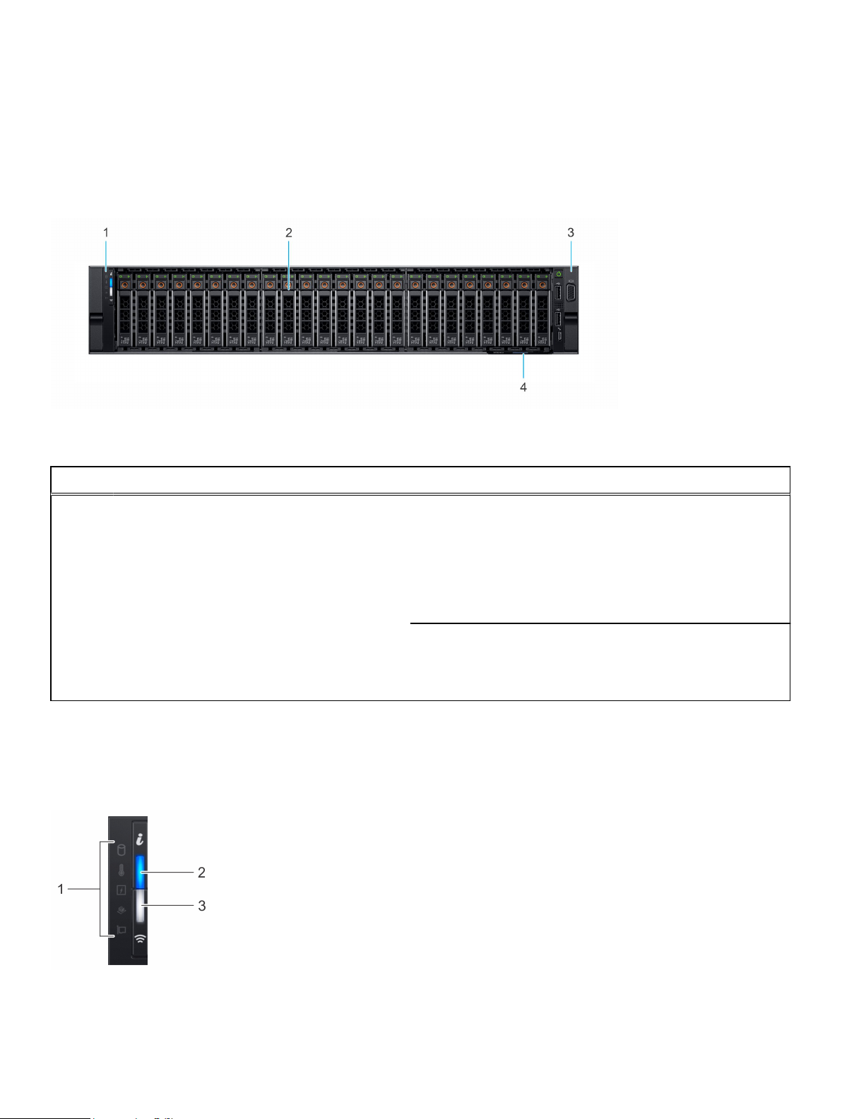
Front view of the R740xd system
The front view displays the features available on the front of the system.
Figure 1 Front view R740xd system
Table 1 Features available on the front of the 24 x 2.5 inch drive R740xd system
Item Ports, panels, and slots Icon Description
1 Left control panel N/A Contains system health and system ID, status LED and optional
iDRAC Quick Sync 2 (wireless).
2 Drive slots N/A Enable you to install drives that are supported on your system. For
more information, see Technical specifications.
3 Right control panel N/A Contains the power button, VGA port, iDRAC Direct micro USB
port, and two USB 2.0 ports.
4 Information tag N/A
The Information Tag is a slide-out label panel that contains system
information such as Service Tag, NIC, MAC address, and so on. If
you have opted for the secure default access to iDRAC, the
Information tag also contains the iDRAC secure default password.
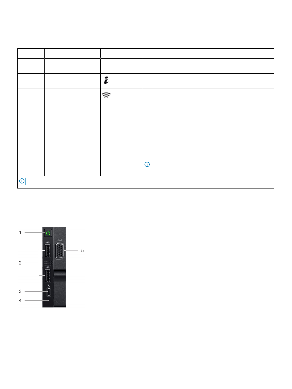
Left control panel view
The left control panel with optional iDRAC Quick Sync 2.0 indicator is explained as follows:
Figure 2
Left control panel
8 R740xd Owner's Guide
VxFlex appliance and VxFlex Ready Node R740xd system overview
Table 2 Left control panel options
Item Indicator or button Icon Description
1 Status LED indicators N/A Indicate the status of the system. For more information, see
Status LED indicators.
2 System health and system
ID indicator
3 iDRAC Quick Sync 2
wireless indicator
(optional)
Note: For more information about the indicator codes, see System diagnostics and indicator codes.
Indicates the system health. For more information, see System
health and system ID indicator codes.
Indicates if the iDRAC Quick Sync 2 wireless option is activated.
The Quick Sync 2 feature allows management of the system using
mobile devices. This feature aggregates hardware/firmware
inventory and various system level diagnostic/error information
that can be used in troubleshooting the system. You can access
system inventory, Dell EMC Lifecycle Controller logs or system
logs, system health status, and also configure iDRAC, BIOS, and
networking parameters. You can also launch the virtual Keyboard,
Video, and Mouse (KVM) viewer and virtual Kernel based Virtual
Machine (KVM), on a supported mobile device. For more
information about the feature, see the
Access Controller User's Guide
Note: iDRAC Quick Sync 2 wireless indicator is available only
on certain configurations.
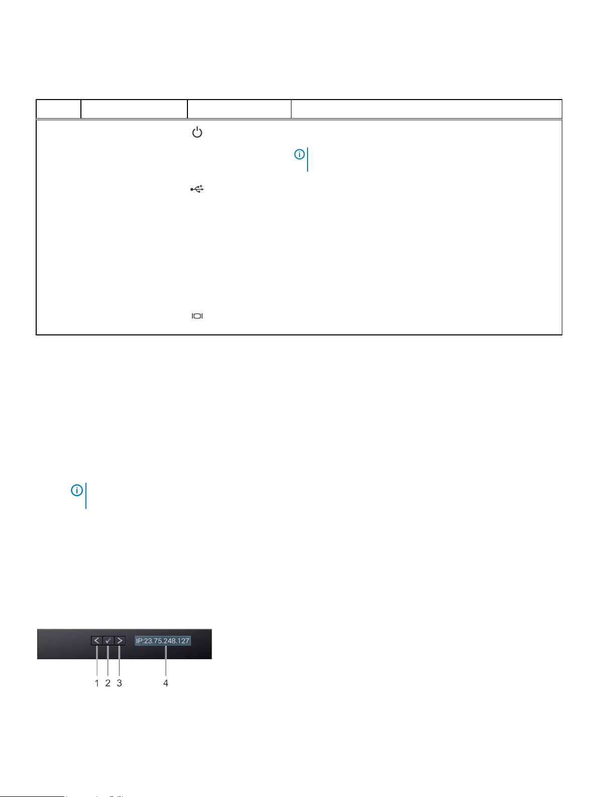
Right control panel view
The right control panel is explained as follows:
Figure 3
Right control panel
Integrated Dell Remote
at www.dell.com/idracmanuals.
R740xd Owner's Guide 9
VxFlex appliance and VxFlex Ready Node R740xd system overview
Table 3 Right control panel features
Item Indicator or button Icon Description
1 Power button Indicates if the system is turned on or off. Press the power button
to manually turn on or off the system.
Note: Press the power button to gracefully shut down an
ACPI-compliant operating system.
2 USB port (2) The USB ports are 4-pin, 2.0-compliant. These ports enable you to
connect USB devices to the system.
3 iDRAC Direct port N/A The iDRAC Direct port is micro USB 2.0-compliant. This port
enables you to access the iDRAC Direct features. For more
information, see the
Guide
at www.dell.com/idracmanuals.
4 iDRAC Direct LED N/A The iDRAC Direct LED indicator lights up to indicate that the
iDRAC Direct port is connected. For more information, see the
iDRAC Direct LED indicator codes.
5 VGA port Enables you to connect a display device to the system. For more
information, see Technical specifications.
Integrated Dell Remote Access Controller User's
LCD panel
The LCD panel provides system information, status, and error messages to indicate whether the system is functioning
correctly or requires attention. The LCD panel can also be used to configure or view the system’s iDRAC IP address.
The LCD panel is available only on the optional front bezel. The optional front bezel is hot pluggable.
The statuses and conditions of the LCD panel are outlined here:
l
The LCD backlight is white during normal operating conditions.
l
When the system needs attention, the LCD backlight turns amber, and displays an error code followed by
descriptive text.
Note:
If the system is connected to a power source and an error is detected, the LCD turns amber
regardless of whether the system is turned on or off.
l
When the system turns off and there are no errors, LCD enters the standby mode after five minutes of
inactivity. Press any button on the LCD to turn it on.
l
If the LCD panel stops responding, remove the bezel and reinstall it.
If the problem persists, see "Getting help" at the end of this publication.
l
The LCD backlight remains off if LCD messaging is turned off using the iDRAC utility, the LCD panel, or other
tools.
Figure 4
LCD panel
10 R740xd Owner's Guide
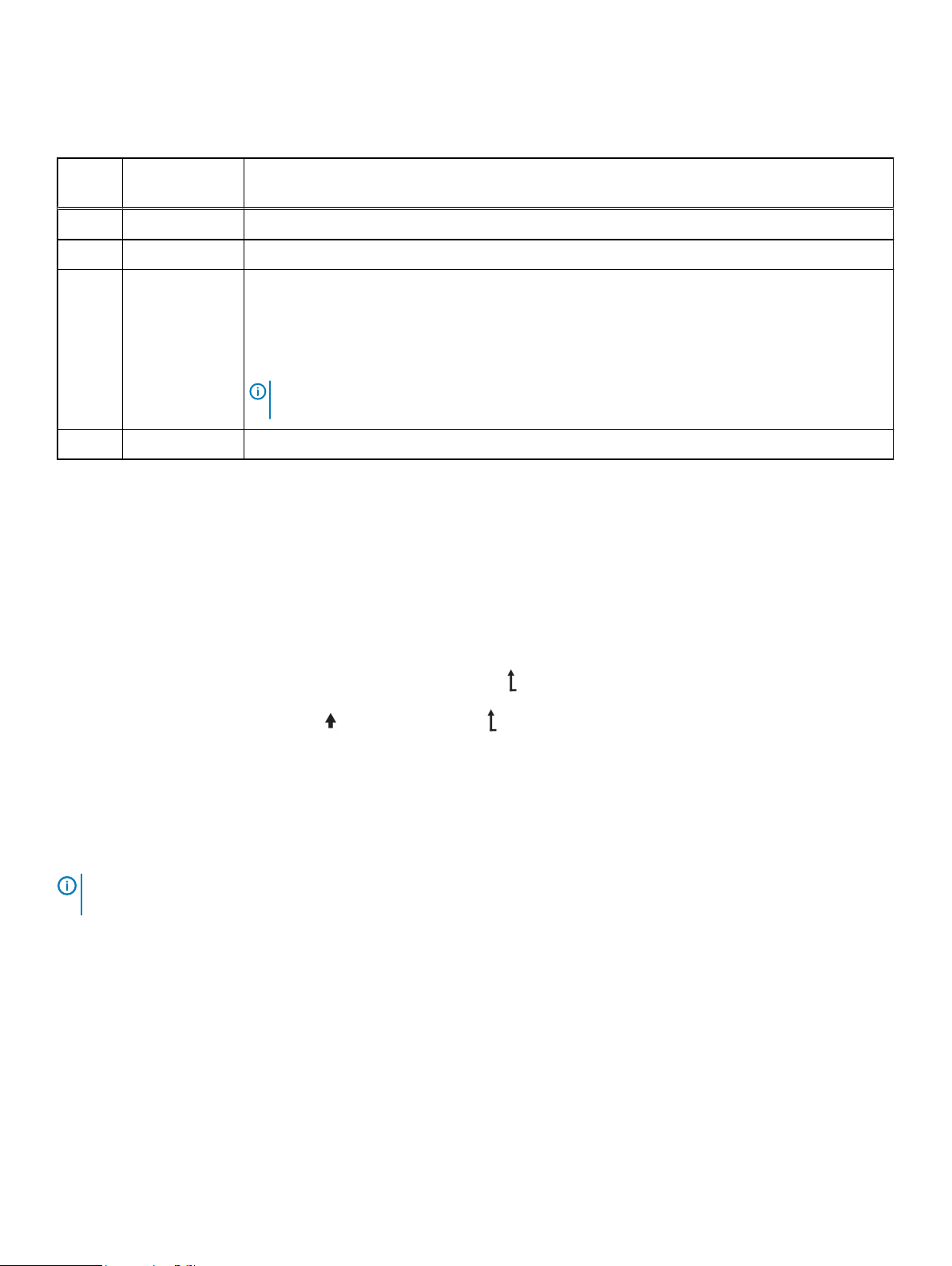
Table 4 LCD panel features
VxFlex appliance and VxFlex Ready Node R740xd system overview
Item Button or
display
1 Left Moves the cursor back in one-step increments.
2 Select Selects the menu item that is highlighted by the cursor.
3 Right Moves the cursor forward in one-step increments.
4 LCD display Displays system information, status, and error messages or iDRAC IP address.
Description
During message scrolling:
l
Press and hold the right button to increase scrolling speed.
l
Release the button to stop.
Note: The display stops scrolling when the button is released. After 45 seconds of inactivity, the
display starts scrolling.
Viewing Home screen
The Home screen displays user-configurable information about the system. This screen is displayed during normal
system operation when there are no status messages or errors. When the system turns off and there are no errors,
LCD enters the standby mode after five minutes of inactivity. Press any button on the LCD to turn it on.
Procedure
1. To view the Home screen, press one of the three navigation buttons (Select, Left, or Right).
2. To navigate to the Home screen from another menu, complete the following steps:
a.
Press and hold the navigation button till the up arrow is displayed.
b.
Navigate to the Home icon using the up arrow .
c. Select the Home icon.
d. On the Home screen, press the Select button to enter the main menu.
Setup menu
The Setup menu contains the following options:
Note:
When you select an option in the Setup menu, you must confirm the option before proceeding to the next
action.
iDRAC
Select DHCP or Static IP to configure the network mode. If Static IP is selected, the available fields are IP,
Subnet (Sub), and Gateway (Gtw). Select Setup DNS to enable DNS and to view domain addresses. Two
separate DNS entries are available.
Set error
Select SEL to view LCD error messages in a format that matches the IPMI description in the SEL. This enables you
to match an LCD message with an SEL entry.
Select Simple to view LCD error messages in a simplified user-friendly description. For information about the
event and error messages generated by the system firmware and agents that monitor system components, see the
Error Code Lookup page at qrl.dell.com
R740xd Owner's Guide 11
VxFlex appliance and VxFlex Ready Node R740xd system overview
Set home
Select the default information to be displayed on the Home screen. See View menu section for the options and
option items that can be set as the default on the Home screen.
View menu
The View menu contains the following options:
Note: When you select an option in the View menu, you must confirm the option before proceeding to the next
action.
iDRAC IP
Displays the IPv4 or IPv6 addresses for iDRAC9. Addresses include DNS (Primary and Secondary), Gateway, IP,
and Subnet (IPv6 does not have Subnet).
MAC
Displays the MAC addresses for iDRAC, iSCSI, or Network devices.
Name
Displays the name of the Host, Model, or User String for the system.
Number
Displays the Asset tag or the Service tag for the system.
Power
Displays the power output of the system in BTU/hr or Watts. The display format can be configured in the Set
home submenu of the Setup menu.
Temperature
Displays the temperature of the system in Celsius or Fahrenheit. The display format can be configured in the Set
home submenu of the Setup menu.
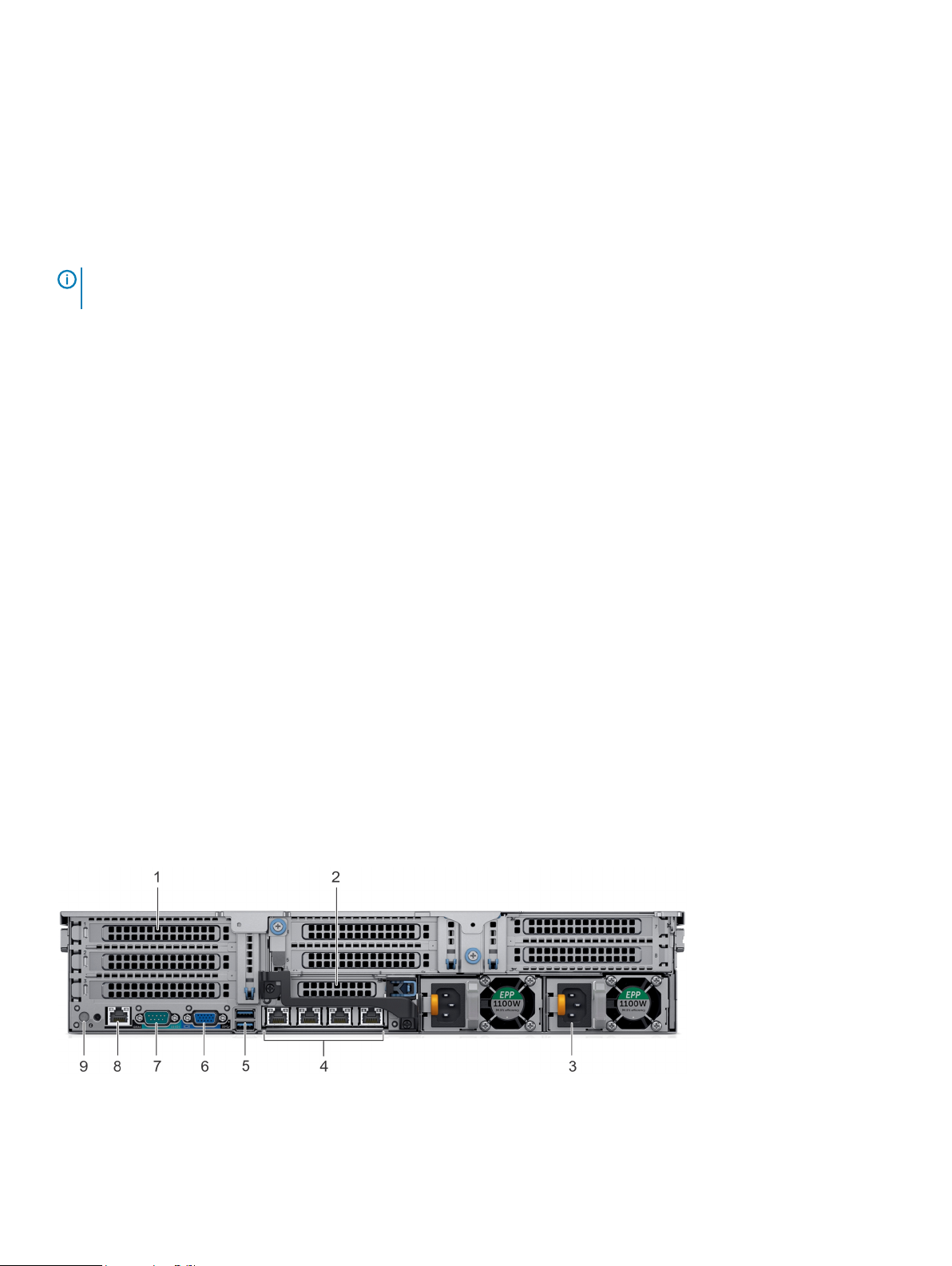
Back view of the R740xd system
The back view displays the features available on the back of the system. The back views are different between the
VxFlex Appliance andVxFlex Ready Node.
Figure 5
Back view of the R740xd
The following table lists the features available on the back view of the VxFlex Ready Node 4 x 2.5 inch drive system
12 R740xd Owner's Guide
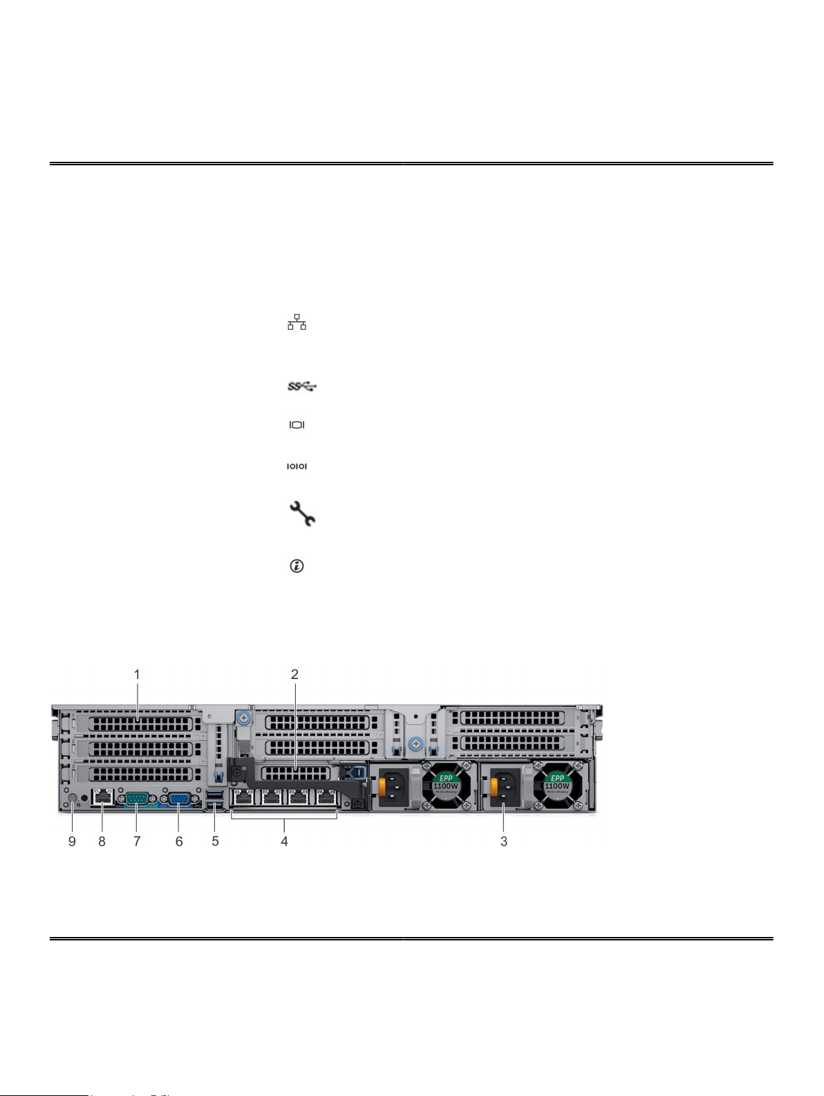
VxFlex appliance and VxFlex Ready Node R740xd system overview
Table 5 Back view features for the R740xd
Item Ports, panels, or slots Icon Description
1 Full-height PCIe expansion
card slot (7)
N/A The PCIe expansion card slot (riser 1, 2 and 3) connects up to
seven full-height PCIe expansion cards to the system. For more
information, see Expansion bus specifications.
2 Half-height PCIe expansion
card slot
N/A The PCIe expansion card slot (riser 2) connects one half-height
PCIe expansion cards to the system. For more information, see
Expansion bus specifications.
3 Power supply unit (2) N/A For more information, see Technical specifications.
4 NIC ports The NIC ports that are integrated on the network daughter card
(NDC) provide network connectivity. For more information about
the supported configurations, see Technical specifications.
5 USB port (2) The USB ports are 9-pin and 3.0-compliant. These ports enable
you to connect USB devices to the system.
6 VGA port Enables you to connect a display device to the system. For more
information, see Technical specifications.
7 Serial port Enables you to connect a serial device to the system. For more
information, see Technical specifications.
8 iDRAC9 dedicated port Enables you to remotely access iDRAC. For more information, see
the
Integrated Dell Remote Access Controller User's Guide
at
www.dell.com/idracmanuals.
10 System identification
button
The System Identification (ID) button is available on the front and
back of the system. Press the system ID button to identify a
system in a rack. You can also use the system ID button to reset
iDRAC and access BIOS using step-through mode.
Figure 6 Back view of the VxFlex Ready Node R740xd 4 x 2.5 inch drive system
Table 6 Back view features for the VxFlex Ready Node R740xd 4 x 2.5 inch drive system
Item Ports, panels, or slots Icon Description
1 Full-height PCIe expansion
card slot (3)
N/A The PCIe expansion card slot (riser 1) connects up to three full-
height PCIe expansion cards to the system. For more information,
see Expansion bus specifications.
R740xd Owner's Guide 13

VxFlex appliance and VxFlex Ready Node R740xd system overview
Table 6 Back view features for the VxFlex Ready Node R740xd 4 x 2.5 inch drive system (continued)
Item Ports, panels, or slots Icon Description
2 Half-height PCIe expansion
card slot
3 Rear handle N/A The rear handle can be removed to enable any external cabling of
4 Rear disk drive (4) N/A This system supports 4 x 2.5 inch drives in the back of the
5 Power supply unit (2) For more information, see Technical specifications
6 NIC ports The NIC ports that are integrated on the network daughter card
7 USB port (2) The USB ports are 9-pin and 3.0-compliant. These ports enable
8 VGA port Enables you to connect a display device to the system. For more
9 Serial port Enables you to connect a serial device to the system. For more
10 iDRAC9 dedicated port Enables you to remotely access iDRAC. For more information, see
N/A The PCIe expansion card slot (riser 2) connects one half-height
PCIe expansion cards to the system. For more information, see
Expansion bus specifications.
PCIe cards that are installed in PCIe expansion card slot 6.
appliance.
(NDC) provide network connectivity. For more information about
the supported configurations, see Technical specifications.
you to connect USB devices to the system.
information, see Technical specifications.
information, see Technical specifications.
the
Integrated Dell Remote Access Controller User's Guide
www.dell.com/idracmanuals.
at
11 System identification
button
The System Identification (ID) button is available on the front and
back of the system. Press the system ID button to identify a
system in a rack. You can also use the system ID button to reset
iDRAC and access BIOS using step-through mode.
Inside the system
Internal components that are hot swappable are marked orange and touch points on the components are marked blue.
CAUTION
troubleshooting and simple repairs as authorized in your product documentation, or as directed by the online or
telephone service and support team. Damage due to servicing that is not authorized by Dell EMC is not covered by
your warranty. Read and follow the safety instructions that are shipped with your product.
Many repairs may only be done by a certified service technician. You should only perform
14 R740xd Owner's Guide
 Loading...