

Dell EMC VMAX 250F, EMC VMAX 450F, EMC VMAX 850F, EMC VMAX 950F Site Planning Manual

EMC® VMAX® All Flash
Site Planning Guide
VMAX 250F, VMAX 450F, VMAX 850F, VMAX 950F
with HYPERMAX OS
REVISION 8.2

Copyright © 2016-2017 Dell Inc. or its subsidiaries. All rights reserved.
Published August 2017
Dell believes the information in this publication is accurate as of its publication date. The information is subject to change without notice.
THE INFORMATION IN THIS PUBLICATION IS PROVIDED “AS-IS.“ DELL MAKES NO REPRESENTATIONS OR WARRANTIES OF ANY KIND
WITH RESPECT TO THE INFORMATION IN THIS PUBLICATION, AND SPECIFICALLY DISCLAIMS IMPLIED WARRANTIES OF
MERCHANTABILITY OR FITNESS FOR A PARTICULAR PURPOSE. USE, COPYING, AND DISTRIBUTION OF ANY DELL SOFTWARE DESCRIBED
IN THIS PUBLICATION REQUIRES AN APPLICABLE SOFTWARE LICENSE.
Dell, EMC, and other trademarks are trademarks of Dell Inc. or its subsidiaries. Other trademarks may be the property of their respective owners.
Published in the USA.
EMC Corporation
Hopkinton, Massachusetts 01748-9103
1-508-435-1000 In North America 1-866-464-7381
www.EMC.com
2 Site Planning Guide VMAX 250F, VMAX 450F, VMAX 850F, VMAX 950F with HYPERMAX OS

CONTENTS
Figures
Tables
Chapter 1
Chapter 2
Chapter 3
7
9
Preface 11
Revision history...........................................................................................14
Pre-planning tasks 15
Before you begin......................................................................................... 16
Tasks to review........................................................................................... 16
VMAX All Flash packaging........................................................................... 17
Delivery and transportation 19
Delivery arrangements................................................................................20
Pre-delivery considerations........................................................................ 20
Moving up and down inclines...................................................................... 20
Shipping and storage environmental requirements......................................21
Specifications 23
Radio frequency interference..................................................................... 24
Recommended minimum distance from RF emitting device........... 24
Power consumption and heat dissipation....................................................25
Adaptive cooling............................................................................ 26
Airflow........................................................................................................ 27
Air volume, air quality, and temperature..................................................... 28
Air volume specifications............................................................... 28
Temperature, altitude, and humidity ranges...................................28
Temperature and humidity range recommendations...................... 28
Air quality requirements.................................................................29
Shock and vibration....................................................................................30
Sound power and sound pressure...............................................................30
Hardware acclimation times........................................................................ 31
Optical multimode cables............................................................................32
Open systems host and SRDF connectivity................................... 32
Chapter 4
Chapter 5
Site Planning Guide VMAX 250F, VMAX 450F, VMAX 850F, VMAX 950F with HYPERMAX OS 3
Data Center Safety and Remote Support 35
Fire suppressant disclaimer........................................................................ 36
Remote support..........................................................................................36
Physical weight and space 39
Floor load-bearing capacity........................................................................ 40
Raised floor requirements...........................................................................40
Physical space and weight.......................................................................... 41

CONTENTS
Chapter 6
Chapter 7
Chapter 8
Position VMAX 250F Bay 43
Bay layout and dimensions..........................................................................44
Tile placement............................................................................................ 45
Casters and leveling feet............................................................................ 45
Cabinet stabilizing...................................................................................... 47
Position VMAX 450F, VMAX 850F, VMAX 950F Bays 49
System bay layouts.................................................................................... 50
Adjacent layouts, VMAX 450F, VMAX 850F, VMAX 950F .............51
Dispersed layout, VMAX 450F, VMAX 850F, VMAX 950F............. 52
Adjacent and dispersed (mixed) layout ......................................... 53
Dimensions for array layouts...................................................................... 54
Tile placement............................................................................................ 55
Caster and leveler dimensions.................................................................... 56
Power cabling, cords and connectors 59
Power distribution equipment, VMAX 250F................................................60
Power distribution unit VMAX 450F, VMAX 850F, VMAX 950F................. 62
Wiring configurations, VMAX 250F............................................................ 64
Wiring configurations, VMAX 450F, VMAX 850F, VMAX 950F.................. 68
Power interface.......................................................................................... 72
Customer input power cabling.................................................................... 72
VMAX 250F customer AC power feed cabling............................... 73
Best practices: Power configuration guidelines.......................................... 74
Power extension cords, connectors, and wiring..........................................74
Single-phase..................................................................................75
Three-phase (International (Wye))................................................80
Three-phase (North American (Delta))......................................... 83
Three-phase (Wye, Domestic).......................................................85
Chapter 9
Chapter 10
Chapter 11
EMC racking for VMAX 250F 87
Two system configurations.........................................................................88
EMC rack requirements for customer components.................................... 88
Third Party Racking Option for VMAX 250F 89
Computer room requirements, VMAX 250F............................................... 90
Customer rack requirements, VMAX 250F................................................. 90
PDU requirements for third party racks, VMAX 250F................................. 91
Component power requirements, VMAX 250F .............................. 91
Power distribution equipment for third-party rack, VMAX 250F....94
Third Party Racking Option for VMAX 450F, VMAX 850F and
VMAX 950F 95
Computer room requirements ....................................................................96
Customer rack requirements ..................................................................... 97
Third party racks with vertical PDUs — RPQ Required ............................. 99
Requirements for third party racks with vertical PDUs (rear-facing)
.....................................................................................................100
Requirements for third party racks with vertical PDUs (inward-
facing) .........................................................................................102
Chassis to chassis grounding.................................................................... 103
4 Site Planning Guide VMAX 250F, VMAX 450F, VMAX 850F, VMAX 950F with HYPERMAX OS

CONTENTS
Chapter 12
Appendix A
Optional kits 105
Overhead routing kit................................................................................. 106
PDU/PDP kits, VMAX 250F......................................................................106
Dispersion kits, VMAX 450F, VMAX 850F.................................................106
Dispersion kits, VMAX 950F......................................................................107
Securing kits............................................................................................. 108
GridRunner kit and customer-supplied cable trough................................. 108
Best Practices for AC Power Connections 111
Best practices overview for AC power connections................................... 112
Selecting the proper AC power connection procedure...............................113
Procedure A: Working with the customer's electrician onsite.................... 114
Procedure A, Task 1: Customer's electrician................................. 115
Procedure A, Task 2: EMC Customer Engineer ............................116
Procedure A, Task 2: EMC Customer Engineer (VMAX 250F)..... 120
Procedure A, Task 3: Customer's electrician................................ 124
Procedure B: Verify and connect.............................................................. 125
Procedure C: Obtain customer verification............................................... 126
PDU labels.................................................................................................126
PDU label part numbers................................................................126
Applying PDU labels, VMAX 250F ................................................127
Applying PDU labels, VMAX 450F, VMAX 850F, VMAX 950F...... 128
Ground the cabinet................................................................................... 128
AC power specifications............................................................................130
Site Planning Guide VMAX 250F, VMAX 450F, VMAX 850F, VMAX 950F with HYPERMAX OS 5

CONTENTS
6 Site Planning Guide VMAX 250F, VMAX 450F, VMAX 850F, VMAX 950F with HYPERMAX OS

FIGURES
1
2
3
4
5
6
7
8
9
10
11
12
13
14
15
16
17
18
19
20
21
22
23
24
25
26
27
28
29
30
31
32
33
34
35
36
37
38
39
40
41
Typical airflow in a hot/cold aisle environment........................................................... 27
Cabinet dimensions and clearances ........................................................................... 44
Placement with floor tiles........................................................................................... 45
Adjacent layout, VMAX 450F, VMAX 850F, VMAX 950F............................................ 51
Dispersed layout, front view....................................................................................... 52
Adjacent and dispersed (mixed) layout, dual-engine array..........................................53
Layout Dimensions, VMAX 450F, VMAX 850F, VMAX 950F...................................... 54
Placement with floor tiles, VMAX 450F, VMAX 850F, VMAX 950F............................55
Caster and leveler dimensions.................................................................................... 56
Power distribution unit (PDU), VMAX 250F, rear view............................................... 61
Power distribution unit (PDU) without installed wire bales, rear view.........................63
Power distribution unit (PDU) with installed wire bales, rear view..............................63
PDU internal wiring, VMAX 250F................................................................................64
Single-phase, PDP internal wiring, VMAX 250F..........................................................65
Three-phase (Delta), PDP internal wiring, VMAX 250F.............................................. 66
Three-phase (Wye), PDP internal wiring, VMAX 250F............................................... 67
Single-phase, horizontal 2U PDU internal wiring, VMAX 450F, VMAX 850F, VMAX
950F...........................................................................................................................69
Three-phase (Delta), horizontal 2U PDU internal wiring, VMAX 450F, VMAX 850F,
VMAX 950F................................................................................................................ 70
Three-phase (Wye), horizontal 2U PDU internal wiring, VMAX 450F, VMAX 850F,
VMAX 950F.................................................................................................................71
Customer input power cabling for VMAX 250F...........................................................73
Single-phase: EF-PW40U-US (VMAX 450F, VMAX 850F), ET-PW40U-US (VMAX
950F), ES-PW40U-US (VMAX 250F)........................................................................ 77
Single-phase: EF-PW40URUS (VMAX 450F, VMAX 850F), ET-PW40URUS (VMAX
950F), ES-PW40URUS (VMAX 250F)....................................................................... 78
Single-phase: EF-PW40UIEC3 (VMAX 450F, VMAX 850F), ET-PW40UIEC3 (VMAX
950F), ES-PW40UIEC3 (VMAX 250F).......................................................................78
Single-phase: EF-PW40UASTL (VMAX 450F, VMAX 850F), ET-PW40UASTL (VMAX
950F), ES-PW40UASTL (VMAX 250F)......................................................................79
Single-phase: E-PW40L730........................................................................................79
Flying leads, three-phase, international: EF-PC3YAFLE (VMAX 450F, VMAX 850F),
ET-PC3YAFLE (VMAX 950F), ES-PC3YAFLE (VMAX 250F), ....................................81
Three-phase, international: EF-PCBL3YAG (VMAX 450F, VMAX 850F), ET-
PCBL3YAG (VMAX 950F), ES-PCBL3YAG (VMAX 250F)......................................... 82
Three-phase, North American, Delta: EF-PCBL3DHR (VMAX 450F, VMAX 850F), ET-
PCBL3DHR (VMAX 950F), ES-PCBL3DHR (VMAX 250F).........................................84
Three-phase, North American, Delta: EF-PCBL3DHH (VMAX 450F, VMAX 850F), ET-
PCBL3DHH (VMAX 950F), ES-PCBL3DHH (VMAX 250F)........................................ 84
Three-phase, domestic (Black and Gray): EF-PCBL3YL23P (VMAX 450F,
VMAX 850F), ET-PCBL3YL23P (VMAX 950F), ES-PCBL3YL23P (VMAX 250F)...... 86
Customer rack dimension requirements .....................................................................98
Requirements for customer rack with rear-facing, vertical PDUs..............................100
Requirements for third party rack with inward-facing, vertical PDUs........................102
Two independent customer-supplied PDUs............................................................... 112
Circuit breakers ON — AC power within specification...............................................115
Circuit breakers OFF — No AC power.......................................................................115
System bay power tee breakers (OFF = pulled out)...................................................116
Connecting AC power, single-phase...........................................................................117
Connecting AC power, three-phase........................................................................... 118
Power zone connections............................................................................................119
PDP power switches for Zone A and B ..................................................................... 120
Site Planning Guide VMAX 250F, VMAX 450F, VMAX 850F, VMAX 950F with HYPERMAX OS 7

FIGURES
42
43
44
45
46
47
48
Connecting AC power ............................................................................................... 121
Power zone connections........................................................................................... 122
Customer input power cabling for VMAX 250F......................................................... 123
Applying the PDU labels ........................................................................................... 127
PDU label , single-phase and three-phase................................................................. 128
Label placement— Customer PDU Information.........................................................128
Location of cabinet ground lugs................................................................................ 129
8 Site Planning Guide VMAX 250F, VMAX 450F, VMAX 850F, VMAX 950F with HYPERMAX OS

TABLES
1
2
3
4
5
6
7
8
9
10
11
12
13
14
15
16
17
18
19
20
21
22
23
24
25
26
27
28
29
30
31
32
33
34
35
36
37
38
39
40
41
42
Typographical conventions used in this content.......................................................... 12
Revision history...........................................................................................................14
Before you begin......................................................................................................... 16
Shipping and storage environmental requirements...................................................... 21
Minimum distance from RF emitting devices.............................................................. 24
Power consumption and heat dissipation....................................................................25
Airflow diagram key.................................................................................................... 27
Maximum air volume, VMAX 250F..............................................................................28
Maximum air volume, VMAX 450F, VMAX 850F, VMAX 950F....................................28
Environmental operating ranges................................................................................. 28
Temperature and humidity..........................................................................................29
Platform shock and vibration......................................................................................30
Sound power and sound pressure levels, A-weighted, VMAX 250F............................ 30
Sound power and sound pressure levels, A-weighted, VMAX 450F, VMAX 850F,
VMAX 950F................................................................................................................30
Hardware acclimation times (systems and components).............................................31
OM3 and OM4 Fibre cables — 50/125 micron optical cable.......................................32
Space and weight requirements, VMAX 250F............................................................. 41
Space and weight requirements, VMAX 450F, VMAX 850F, VMAX 950F................... 41
Adjacent layout diagram key, VMAX 450F, VMAX 850F, VMAX 950F ....................... 51
Caster and leveler dimensions diagram key................................................................ 56
Extension cords and connectors options – single-phase.............................................75
Extension cords and connectors options – three-phase international (Wye)..............80
Extension cords and connectors options – three-phase North American (Delta)....... 83
Extension cords and connectors options – three-phase Wye, domestic..................... 85
Engine and 2U SPS power requirements.................................................................... 92
25 drive DAE power requirements.............................................................................. 93
Power Distribution Equipment C13 Outlet Connections required for 1 V-Brick ...........94
Power Distribution Equipment C13 Outlet Connections required for 2 V-Bricks ........ 94
Overhead routing models, VMAX 250F..................................................................... 106
Overhead routing models, VMAX 450F, VMAX 850F, VMAX 950F........................... 106
PDU/PDP kits for VMAX 250F................................................................................. 106
Dispersion kit model numbers, VMAX 450F, VMAX 850F..........................................107
Dispersion kit model numbers, VMAX 950F...............................................................107
Securing kit models, VMAX 250F..............................................................................108
Securing kit models, VMAX 450F, VMAX 850F, VMAX 950F....................................108
Bottom routing model, VMAX 250F.......................................................................... 109
Bottom routing model, VMAX 450F, VMAX 850F, VMAX 950F................................ 109
Procedure options for AC power connection ............................................................ 113
VMAX 250F label part numbers.................................................................................126
VMAX 450F, VMAX 850F, VMAX 950F label part numbers, EMC racks ...................126
Input power requirements - single-phase, North American, International, Australian
..................................................................................................................................130
Input power requirements - three-phase, North American, International, Australian
.................................................................................................................................. 131
Site Planning Guide VMAX 250F, VMAX 450F, VMAX 850F, VMAX 950F with HYPERMAX OS 9

TABLES
10 Site Planning Guide VMAX 250F, VMAX 450F, VMAX 850F, VMAX 950F with HYPERMAX OS

Preface
Note
As part of an effort to improve its product lines, EMC periodically releases revisions of
its software and hardware. Therefore, some functions described in this document
might not be supported by all versions of the software or hardware currently in use.
The product release notes provide the most up-to-date information on product
features.
Contact your EMC representative if a product does not function properly or does not
function as described in this document.
This document was accurate at publication time. New versions of this document might
be released on EMC Online Support (https://support.emc.com). Check to ensure that
you are using the latest version of this document.
Purpose
This document is intended for use by customers and/or company representatives who
want to plan the purchase and installation of a VMAX All Flash system.
Audience
This document is intended for use by customers or company representatives.
Related documentation
The following documentation portfolios contain documents related to the hardware
platform and manuals needed to manage your software and storage system
configuration. Also listed are documents for external components which interact with
your array.
EMC VMAX All Flash Product Guide for VMAX 250F, 450F, 850F, 950F with HYPERMAX
OS
Provides product information regarding the purchase of a VMAX 250F, 450F,
850F, 950F with HYPERMAX OS.
EMC VMAX Securing Kit Installation Guide
Describes how to install the securing kit on a VMAX3 Family array or VMAX All
Flash array.
EMC VMAX Best Practices Guide for AC Power Connections
Describes the best practices to assure fault-tolerant power to a VMAX3 Family
array or VMAX All Flash array.
EMC VMAX Power-down/Power-up Procedure
Describes how to power-down and power-up a VMAX3 Family array or VMAX All
Flash array.
HYPERMAX OS 5977.xxx.xxx for EMC VMAX3 Family and VMAX All Flash Release Notes
Describes new features and any known limitations.
Special notice conventions used in this document
EMC uses the following conventions for special notices:
Preface
11
DANGER
WARNING
CAUTION
NOTICE
Note
Preface
Indicates a hazardous situation which, if not avoided, will result in death or
serious injury.
Indicates a hazardous situation which, if not avoided, could result in death or
serious injury.
Indicates a hazardous situation which, if not avoided, could result in minor or
moderate injury.
Addresses practices not related to personal injury.
Presents information that is important, but not hazard-related.
Typographical conventions
EMC uses the following type style conventions in this document:
Table 1
Typographical conventions used in this content
Bold
Italic
Monospace
Monospace italic
Monospace bold
[ ] Square brackets enclose optional values
| Vertical bar indicates alternate selections - the bar means “or”
Used for names of interface elements, such as names of windows,
dialog boxes, buttons, fields, tab names, key names, and menu paths
(what the user specifically selects or clicks)
Used for full titles of publications referenced in text
Used for:
l
System code
l
System output, such as an error message or script
l
Pathnames, filenames, prompts, and syntax
l
Commands and options
Used for variables
Used for user input
{ } Braces enclose content that the user must specify, such as x or y or
z
... Ellipses indicate nonessential information omitted from the example
Where to get help
Support, product and licensing information can be obtained as follows:
12 Site Planning Guide VMAX 250F, VMAX 450F, VMAX 850F, VMAX 950F with HYPERMAX OS

Preface
Product information
EMC technical support, documentation, release notes, software updates, or
information about EMC products can be obtained on the https://
support.emc.com site (registration required).
Technical support
To open a service request through the https://support.emc.com site, you must
have a valid support agreement. Contact your EMC sales representative for
details about obtaining a valid support agreement or to answer any questions
about your account.
Your comments
Your suggestions help us improve the accuracy, organization, and overall quality of the
documentation. Send your comments and feedback to:
VMAXContentFeedback@emc.com
13
Preface
Revision history
Table 2 Revision history
Revision Description and/or change Date
released
8.2 Fixed typo for single-phase PDP wiring configuration. August, 2017
8.1 Added recommendation for chassis to chassis grounding for
multiple bay systems.
8.0 Added VMAX 950F product content. May, 2017
7.0 Updated power and heat dissipation numbers for VMAX 250F.
Corrected formula for 3rd party rack cabinet width
requirements.
6.0 Added VMAX 250F product content and adjusted document
architecture for readability.
Updated wiring configuration diagrams and content for new
2U PDUs.
Updated power distribution unit recommendations for
overhead power.
5.0 In Position Bays chapter, removed an incorrect image. June, 2016
4.0 Added content to support option for 3rd-party racks. May, 2016
3.0 Modified topics to reflect Slot 9 is reserved for compression. April, 2016
2.0 Updated values in the power and heat dissipation specification
table.
1.0 First release of the VMAX All Flash with EMC HYPERMAX OS
for VMAX 450F, VMAX 450FX, VMAX 850F, and
VMAX 850FX.
June, 2017
September,
2016
August, 2016
February,
2016
February,
2016
14 Site Planning Guide VMAX 250F, VMAX 450F, VMAX 850F, VMAX 950F with HYPERMAX OS

CHAPTER 1
Pre-planning tasks
This chapter includes:
l
Before you begin.................................................................................................16
l
Tasks to review...................................................................................................16
l
VMAX All Flash packaging...................................................................................17
Pre-planning tasks 15

Pre-planning tasks
Before you begin
VMAX All Flash arrays are designed for installation in data centers that provide:
l
l
l
l
l
l
Raised floors are preferred.
For information regarding overhead cable routing, see: Overhead routing kit on page
106.
To prepare the site for an array, meet with your EMC Systems Engineer and EMC
Customer Engineer and determine what is needed to prepare for delivery and
installation.
One or more sessions may be necessary to finalize installation plans.
Sufficient physical space
Controlled temperature and humidity
Airflow and ventilation
Power and grounding
System cable routing facilities
Fire protection
Tasks to review
The following table provides a list of tasks to review during the planning process:
Table 3
Task Comments and/or Provide
Identify power requirements with customer and customer
electrician.
For customer-supplied third party rack support, see the
detailed physical requirements in Third Party Racking Option
for VMAX 250F on page 89 and Third Party Racking Option
for VMAX 450F, VMAX 850F and VMAX 950F on page 95.
Complete the
Survey
Installation Planning Task Sheet and Presite
in DXCX.
Before you begin
External AC power must be supplied from an independent
customer-supplied power distribution unit (PDU).
EMC recommends that the customer’s electrician be available
at the installation site for regular and third party racked
arrays.
Best Practices for AC Power Connections on page 111
provides details.
The field representative working the order must:
l
Review the requisite information regarding the third party
racking option.
l
In Sizer, select the desired configuration. In the
Hardware Options screen, under Rack Type, select
Third Party.
l
Connection for ConnectEMC to dial home to the EMC
Support Center. Data Center Safety and Remote Support
on page 35 provides additional details on remote
support.
16 Site Planning Guide VMAX 250F, VMAX 450F, VMAX 850F, VMAX 950F with HYPERMAX OS

Table 3 Before you begin (continued)
Task Comments and/or Provide
l
Power, cooling and ventilation, humidity control, floor
load capability, system placement, and service clearances
as required in the data center.
VMAX All Flash packaging
VMAX All Flash arrays offer the simplest packaging ever delivered for a platform. The
basic building block is an appliance-based entity called a V-Brick in open system arrays
and a zBrick in mainframe arrays. Each V-Brick or zBrick includes:
l
An engine with two directors (the redundant data storage processing unit)
l
Flash capacity in Drive Array Enclosures (DAEs):
n
VMAX 250F: Two 25-slot DAEs with a minimum base capacity of 13TBu
n
VMAX 450F, VMAX 850F: Two 120-slot DAEs with a minimum base capacity of
53TBu
n
VMAX 950F (open or mixed systems): Two 120-slot DAEs with a minimum base
capacity of 53TBu
n
VMAX 950F (mainframe systems): Two 120-slot DAEs with a minimum base
capacity of 13TBu
l
Multiple software packages are available: F and FX packages for open system
arrays and zF and zFX for mainframe arrays.
Pre-planning tasks
This document uses the term V-Brick for planning purposes. All guidelines that apply
to V-Bricks also apply to zBricks.
VMAX All Flash packaging 17

Pre-planning tasks
18 Site Planning Guide VMAX 250F, VMAX 450F, VMAX 850F, VMAX 950F with HYPERMAX OS

CHAPTER 2
Delivery and transportation
This chapter includes:
l
Delivery arrangements....................................................................................... 20
l
Pre-delivery considerations................................................................................20
l
Moving up and down inclines..............................................................................20
l
Shipping and storage environmental requirements............................................. 21
Delivery and transportation 19

NOTICE
Delivery and transportation
Delivery arrangements
Delivery within the United States or Canada is by air-ride truck with custom-designed
shipping material, crate, and pallet. International delivery normally involves air freight.
Unless otherwise instructed, the EMC Traffic Department arranges for delivery
directly to the customer’s computer room. To ensure successful delivery of the
system, EMC has formed partnerships with specially selected moving companies.
These companies have moving professionals trained in the proper handling of large,
sensitive equipment. These companies provide the appropriate personnel, floor
layments, and any ancillary moving equipment required to facilitate delivery. Moving
companies should check general guidelines, weights, and dimensions.
Inform EMC of any labor union-based restrictions or security clearance requirements
prior to delivery.
Pre-delivery considerations
Take into account the following considerations prior to the delivery at your site:
l
Weight capacities of the loading dock, tailgate, and service elevator if delivery is to
a floor other than the receiving floor.
l
Length and thickness of covering required for floor protection.
l
Equipment ramp availability if the receiving floor is not level with computer room
floor.
l
Set up the necessary network and gateway access to accommodate EMC Secure
Remote Support (ESRS) so that it will be available and operable for the installation
date.
Moving up and down inclines
To prevent tipping when moving up and down inclines, the following guidelines are
recommended:
l
When moving cabinets, all doors/drawers should be closed.
l
When moving the cabinet down an incline, the front of the cabinet must go first.
l
When moving the cabinet up an incline, the rear of the bay goes last.
All portions of the bay will clear ramp and threshold slopes up to 1:10 (rise to run
ratio), per Code of Federal Regulations — ADA Standards for Accessible Design, 28
CFR Part 36.
20 Site Planning Guide VMAX 250F, VMAX 450F, VMAX 850F, VMAX 950F with HYPERMAX OS
Delivery and transportation
Shipping and storage environmental requirements
The following table provides the environmental requirements for shipping and storage:
Table 4 Shipping and storage environmental requirements
Condition Setting
Ambient temperature -40° to 149° F (-40° to 65° C)
Temperature gradient 43.2° F/hr (24° C/hr)
Relative humidity 10% to 90% noncondensing
Maximum altitude 25,000 ft (7619.7 m)
Storage time (unpowered) Recommendation: Do not exceed 6
consecutive months of unpowered storage.
Shipping and storage environmental requirements 21

Delivery and transportation
22 Site Planning Guide VMAX 250F, VMAX 450F, VMAX 850F, VMAX 950F with HYPERMAX OS

CHAPTER 3
Specifications
This chapter includes:
l
l
l
l
l
l
l
l
Radio frequency interference.............................................................................24
Power consumption and heat dissipation........................................................... 25
Airflow................................................................................................................27
Air volume, air quality, and temperature.............................................................28
Shock and vibration........................................................................................... 30
Sound power and sound pressure...................................................................... 30
Hardware acclimation times................................................................................31
Optical multimode cables................................................................................... 32
Specifications
23
Specifications
Radio frequency interference
Electro-magnetic fields, which include radio frequencies can interfere with the
operation of electronic equipment. EMC Corporation products have been certified to
withstand radio frequency interference (RFI) in accordance with standard
EN61000-4-3. In Data Centers that employ intentional radiators, such as cell phone
repeaters, the maximum ambient RF field strength should not exceed 3 Volts /meter.
The field measurements should be taken at multiple points in close proximity to EMC
Corporation equipment. It is recommended to consult with an expert prior to installing
any emitting device in the Data Center. In addition, it may be necessary to contract an
environmental consultant to perform the evaluation of RFI field strength and address
the mitigation efforts if high levels of RFI are suspected.
The ambient RFI field strength is inversely proportional to the distance and power
level of the emitting device.
Recommended minimum distance from RF emitting device
The following table provides the recommended minimum distances between EMC
arrays and RFI emitting equipment. Use these guidelines to verify that cell phone
repeaters or other intentional radiator devices are at a safe distance from the EMC
Corporation equipment.
Table 5
Minimum distance from RF emitting devices
Repeater power level
1 Watt 9.84 ft (3 m)
2 Watt 13.12 ft (4 m)
5 Watt 19.69 ft (6 m)
7 Watt 22.97 ft (7 m)
10 Watt 26.25 ft (8 m)
12 Watt 29.53 ft (9 m)
15 Watt 32.81 ft (10 m)
a.
Effective Radiated Power (ERP)
a
Recommended minimum distance
24 Site Planning Guide VMAX 250F, VMAX 450F, VMAX 850F, VMAX 950F with HYPERMAX OS
Power consumption and heat dissipation
NOTICE
EMC provides the EMC Power Calculator to refine the power and heat figures to more
closely match your array. Contact your EMC Sales Representative or use the EMC
Power Calculator for specific supported configurations. The following table provides
calculations of maximum power and heat dissipation.
Power consumption and heat dissipation details vary based on the number of system
and storage bays. Ensure that the installation site meets these worst case
requirements.
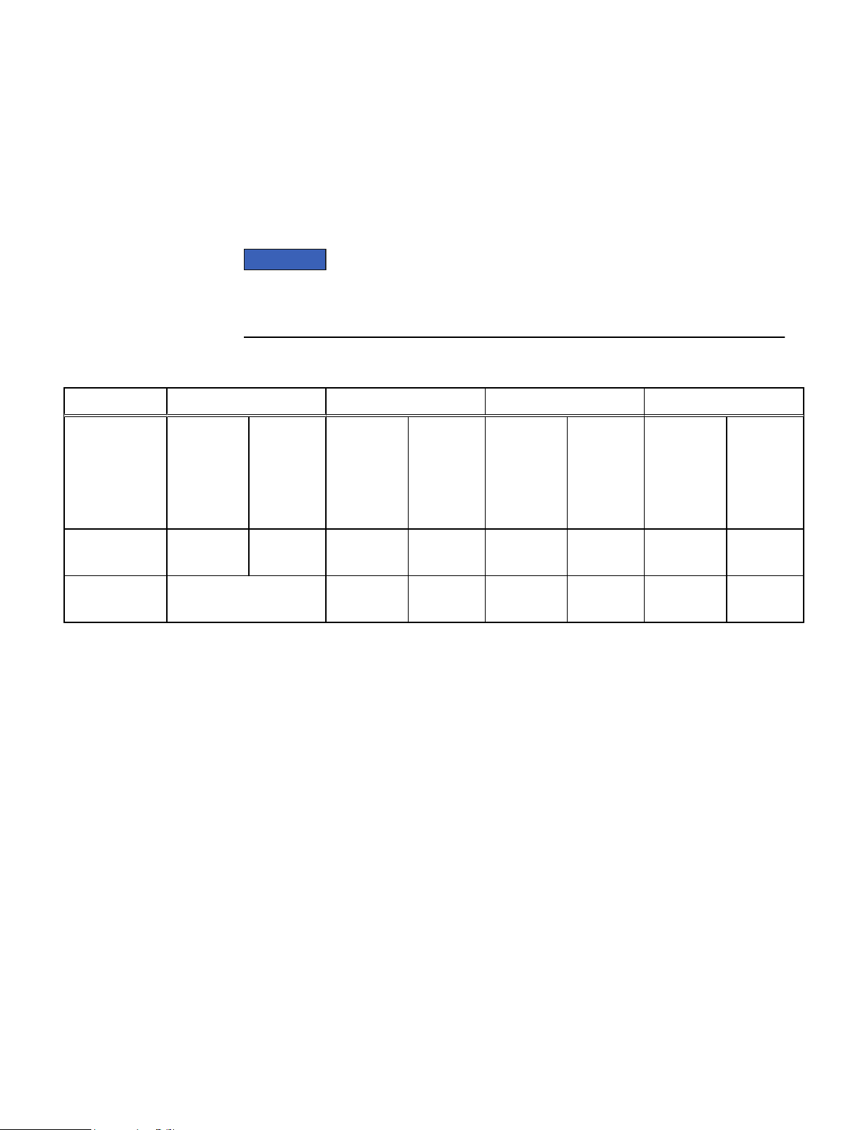
Table 6 Power consumption and heat dissipation
VMAX 250F VMAX 450F VMAX 850F VMAX 950F
Specifications
Maximum power
and heat
dissipation at
<26°C and
a
>35°C
System bay 1
Dual V-Brick
System bay 2
Dual V-Brick
b
a.
Power values and heat dissipations shown at >35°C reflect the higher power levels associated with both the battery recharge
cycle, and the initiation of high ambient temperature adaptive cooling algorithms. Values at <26°C are reflective of more steady
state maximum values during normal operation.
b.
Power values for system bay 2 and all subsequent system bays where applicable.
Maximum
total power
consumption
<26°C /
>35°C
(kVA)
4.13 / 5.19 14,090 /
N/A 6.28 / 8.38 21,415 /
Maximum
heat
dissipation
<26°C /
>35°C
(Btu/Hr)
17,698
Maximum
total power
consumption
<26°C /
>35°C
(kVA)
6.69 / 9.05 22,813 /
Maximum
heat
dissipation
<26°C /
>35°C
(Btu/Hr)
30,861
28,576
Maximum
total power
consumption
<26°C /
>35°C
(kVA)
6.94 / 9.30 23,665 /
6.49 / 8.59 22,131 /
Maximum
heat
dissipation
<26°C /
>35°C
(Btu/Hr)
31,713
29,292
Maximum
total power
consumption
<26°C /
>35°C
(kVA)
7.25 / 9.61 24,712 /
6.80 / 8.90 23,178 /
Maximum
heat
dissipation
<26°C /
>35°C
(Btu/Hr)
32,760
30,339
Power consumption and heat dissipation 25

Specifications
Adaptive cooling
The systems apply adaptive cooling based on customer environments to save energy.
Engines and DAEs access thermal data through components located within their
enclosures. Based on ambient temperature and internal activity, they set the cooling
fan speeds. As the inlet temperatures increase, the adaptive cooling increases the fan
speeds, with the resulting platform power increasing up to the maximum values shown
below. These values, along with the SPS recharge power consumption, contribute to
the maximum system power consumption values over 35°C shown in Table 6 on page
25.
VMAX 250F
l
DAE25 (25 Drives) = 7VA - 24 BTU/hr
l
Engine = 255VA - 870 BTU/hr
VMAX 450F, VMAX 850F
l
DAE120 (2.5 Drives) = 305VA - 1024 BTU/hr
l
Engine = 180VA - 614 BTU/hr
VMAX 950F
l
DAE120 (2.5 Drives) = 305VA - 1024 BTU/hr
l
Engine = 255VA - 870 BTU/hr
26 Site Planning Guide VMAX 250F, VMAX 450F, VMAX 850F, VMAX 950F with HYPERMAX OS
Airflow
5
6
5
4
4
8
7
9
9
1 1
22
3
Specifications
Systems are designed for typical hot aisle/cold aisle data center cooling environments
and installation:
l
On raised or nonraised floors.
l
In hot aisle/cold aisle arrangements.
The airflow provides less mixing of hot and cold air, which can result in a higher return
temperature to the computer room air conditioner (CRAC). This promotes better heat
transfer outside the building and achieves higher energy efficiency and lower Power
Usage Effectiveness (PUE). Additional efficiency can be achieved by sequestering the
exhaust air completely and connecting ducts directly to a CRAC unit or to the outside.
Best practice is to place a perforated floor tile in front of each bay to allow adequate
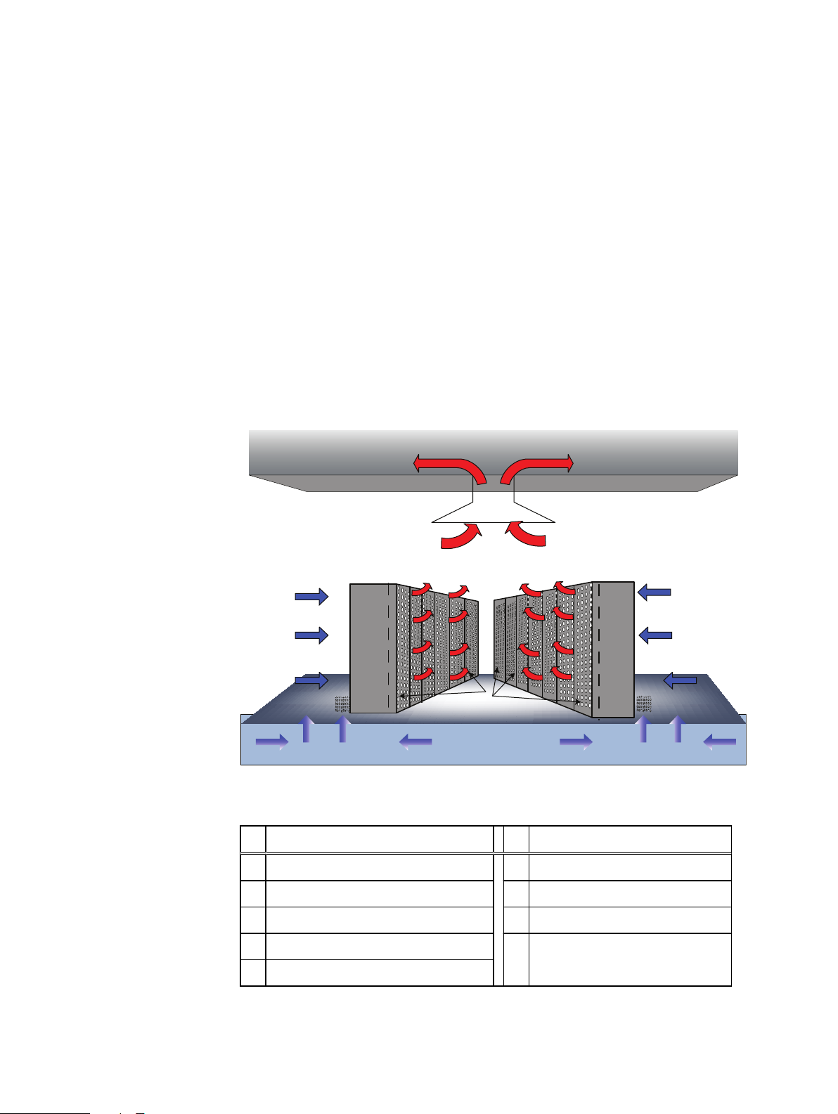
cooling air supply when installing on a raised floor. The following figure shows typical
airflow in a hot aisle/ cold aisle environment.
Figure 1 Typical airflow in a hot/cold aisle environment
Table 7 Airflow diagram key
# Description # Description
1 To refrigeration unit 6 Hot aisle
2 Suspended ceiling 7 Perforated rear doors
3 Air return 8 Pressurized floor
4 System bays 9 Perforated floor tile
5 Cold aisle
Airflow 27
Specifications
Air volume, air quality, and temperature
The installation site must meet certain recommended requirements for air volume,
temperature, altitude, and humidity ranges, and air quality.
Air volume specifications
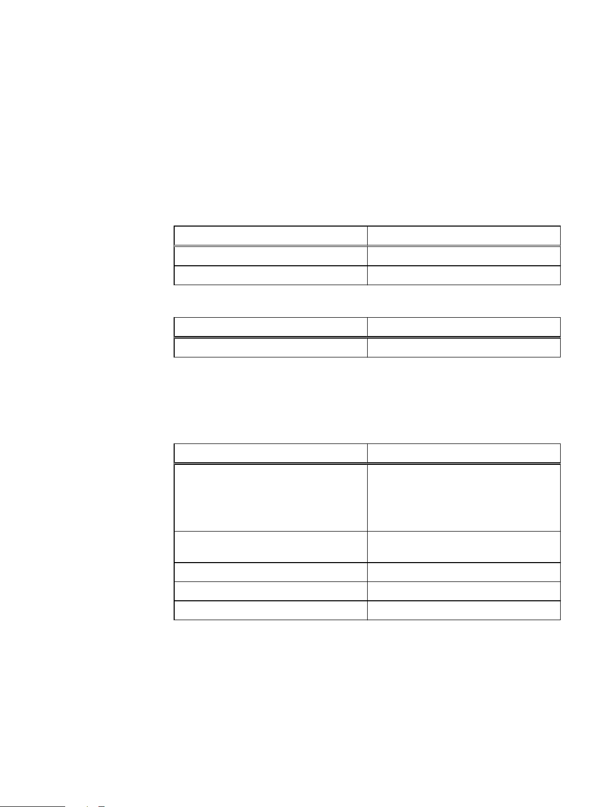
The following table provides the recommended maximum amount of air volume.
Table 8 Maximum air volume, VMAX 250F
Bay Units
System bay, 1 V-Brick 490 cfm (13.9 m3/min)
System bay, 2 V-Bricks 980 cfm (27.8 m3/min)
Table 9 Maximum air volume, VMAX 450F, VMAX 850F, VMAX 950F
Bay Units
System bay 1,325 cfm (37.4 m3/min)
Temperature, altitude, and humidity ranges
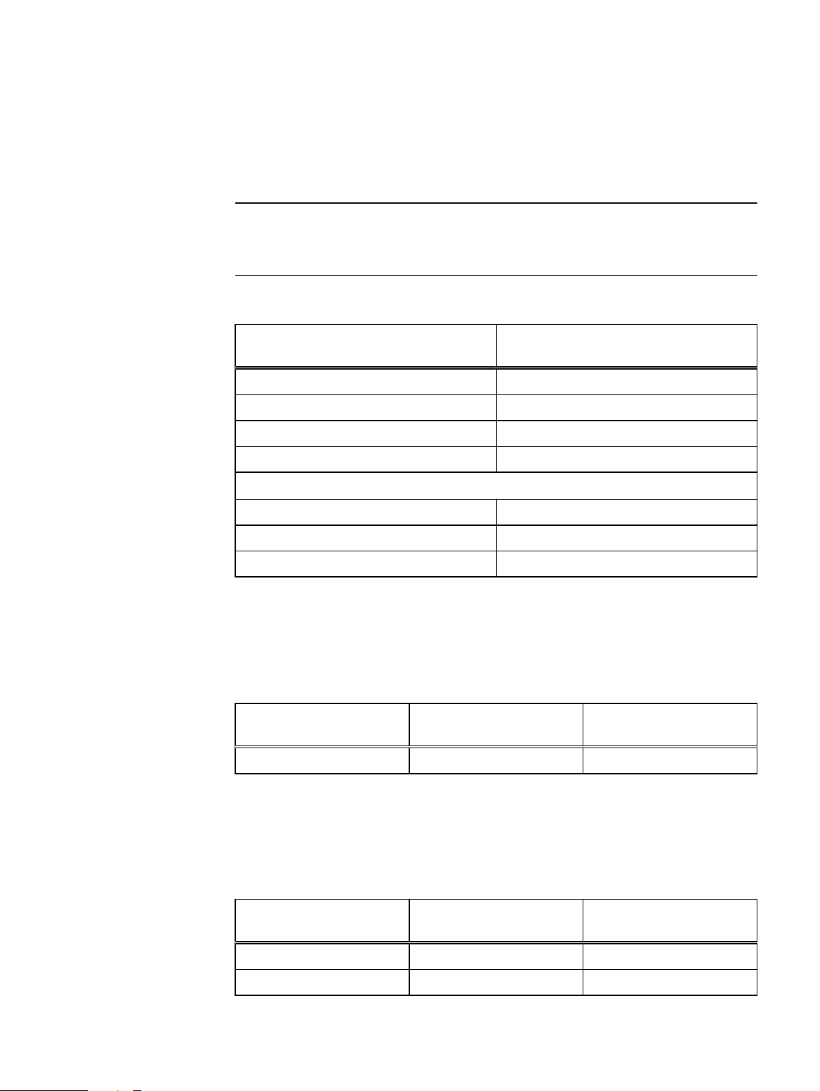
The following table provides the recommended environmental operating ranges.
Table 10
Condition System
Operating temperature and operating
altitude
Operating altitude (maximum) 10,000 ft (3,048 m) 1.1° derating per 1,000
Operating relative humidity extremes 20% to 80% noncondensing
Operating rate of temperature change 9° F/Hr (5° C/Hr)
Thermal excursion 122° F (48° C) (up to 24 hours)
Environmental operating ranges
a
a.
These values apply to the inlet temperature of any component within the bay.
b.
Derating equals an operating temperature of 29.25° C
l
50° – 90° F (10° to 32° C) at 7,500 ft
(2,286 m)
l
50° – 95° F (10° to 35° C) at 3,317 ft
(950 m)
b
ft
Temperature and humidity range recommendations
The following table provides the recommended operating and humidity ranges to
ensure long-term reliability, especially in environments where air quality is a concern.
28 Site Planning Guide VMAX 250F, VMAX 450F, VMAX 850F, VMAX 950F with HYPERMAX OS

Table 11 Temperature and humidity
Note
Condition System
Operating temperature range 64°— 75° F (18° to 24° C)
Operating relative humidity range 40 — 55%
Air quality requirements
VMAX All Flash arrays are designed to be consistent with the requirements of the
American Society of Heating, Refrigeration and Air Conditioning Engineers (ASHRAE)
Environmental Standard Handbook and the most current revision of Thermal
Guidelines for Data Processing Environments, ASHRAE TC 9.9 2011.
The arrays are best suited for Class 1A Datacom environments, which consist of tightly
controlled environmental parameters, including temperature, dew point, relative
humidity and air quality. These facilities house mission critical equipment and are
typically fault tolerant, including the air conditioners. In a data center environment, if
the air conditioning fails and the temperature is lost, a vault may occur to protect
data.
The data center should maintain a cleanliness level as identified in ISO 14664-1, class 8
for particulate dust and pollution control. The air entering the data center should be
filtered with a MERV 11 filter or better. The air within the data center should be
continuously filtered with a MERV 8 or better filtration system. In addition, efforts
should be maintained to prevent conductive particles, such as zinc whiskers, from
entering the facility.
The allowable relative humidity level is 20–80% non condensing, however, the
recommended operating environment range is 40–55%. For data centers with
gaseous contamination, such as high sulfur content, lower temperatures and humidity
are recommended to minimize the risk of hardware corrosion and degradation. In
general, the humidity fluctuations within the data center should be minimized. It is also
recommended that the data center be positively pressured and have air curtains on
entry ways to prevent outside air contaminants and humidity from entering the
facility.
For facilities below 40% relative humidity (RH), EMC recommends using grounding
straps when contacting the equipment to avoid the risk of electrostatic discharge
(ESD), which can harm electronic equipment.
Specifications
As part of an ongoing monitoring process for the corrosiveness of the environment,
EMC recommends placing copper and silver coupons (per ISA 71.04-1985, Section 6.1
Reactivity) in airstreams representative of those in the data center. The monthly
reactivity rate of the coupons should be less than 300 Angstroms. When monitored
reactivity rate is exceeded, the coupon should be analyzed for material species and a
corrective mitigation process emplaced.
Air quality requirements 29
Note
Specifications
Shock and vibration
The following table provides the platform shock and vibration maximums and the
transportation shock and vibration levels (in the vertical direction).
Levels shown apply to all three axes, and should be measured with an accelerometer in
the equipment enclosures within the cabinet.
Table 12 Platform shock and vibration
Platform condition Response measurement level (should
Non operational shock 10 G's, 7 ms duration
Operational shock 3 G's, 11 ms duration
Non operational random vibration .40 Grms, 5-500Hz, 30 minutes
not exceed)
Operational random vibration .21 Grms, 5-500Hz, 10 minutes
Packaged system condition
Transportation shock 10 G's, 12 ms duration
Transportation random vibration 1.15 Grms, 1 hour
Frequency range 1-200 Hz
Sound power and sound pressure
VMAX 250F
Table 13
Configuration Sound power levels
System bay, 1 V-Brick 7.1 58.9
VMAX 450F, VMAX 850F, VMAX 950F
Sound power and sound pressure levels, A-weighted, VMAX 250F
(LWAd) (B)
a.
Declared noise emissions with.3B correction factor added per ISO9296.
b.
Measured at the four bystander positions per ISO7779
a
(LpA) (dB)
b
Sound pressure levels
Table 14
950F
Configuration Sound power levels
System bay (max) 7.9 66
System bay (min) 7.6 63
30 Site Planning Guide VMAX 250F, VMAX 450F, VMAX 850F, VMAX 950F with HYPERMAX OS
Sound power and sound pressure levels, A-weighted, VMAX 450F, VMAX 850F, VMAX
Sound pressure levels
(LWAd) (B)
a.
Declared noise emissions with.3B correction factor added per ISO9296.
a
(LpA) (dB)
b
 Loading...