

Page 1
Dell EMC Networking
N3024EP-ON、N3024ET-ON、
N3024EF-ON、N3048EP-ON、
N3048ET-ON 交換器
入門指南
安規型號:E06W、E07W
Page 2

註、警示與警告
註 : 「註」表示可以幫助您更有效地使用交換器的重要資訊。
警示: 「警示」表示有可能會損壞硬體或導致資料遺失,並告訴您如何避
免發生此類問題。
警告: 「警告」表示有可能會導致財產損失、人身傷害甚至死亡。
____________________
© 2018 Dell Inc. 或其子公司。版權所有,翻印必究。本產品受美國與國際著作權及智慧財
產權法保護。Dell 和 Dell 徽標為 Dell Inc. 在美國及 / 或其他司法管轄區的徽標。此處提及的
所有其他標記和名稱均為其各自公司的商標。
安規型號:E06W、E07W
2018 年 3 月 P/N DWM9T_A00_ZH-TW 修訂版 A00
Page 3

目錄
1 簡介 . . . . . . . . . . . . . . . . . . . . . . . . . . . . 5
N3000ET-ON/N3000EP-ON 硬體概觀 . . . . . . . . . . 5
N3024EP-ON 及 N3048EP-ON PoE 交換器的耗
電量和功率預算
. . . . . . . . . . . . . . . . . 5
通風系統
. . . . . . . . . . . . . . . . . . . . . 6
2 N3000ET-ON/N3000EP-ON 安裝 . . . . . . . . 8
機架安裝 N3000ET-ON/N3000EP-ON 交換器 . . . . . . 8
安裝在機架中
堆疊多台 N3000ET-ON/N3000EP-ON 交換器
. . . . . . . . . . . . . . . . . . . 8
. . . . . . 10
3 啟動和設定 N3000ET-ON/
N3000EP-ON 交換器
將 N3000ET-ON/N3000EP-ON 交換器連接至終端機 . . 12
N3000ET-ON/N3000EP-ON 將 交換器連接至電源
. . . . . . . . . . . . . . . 11
. . . 13
交流電和直流電源連接
啟動 N3000ET-ON/N3000EP-ON 交換器
進行 N3000ET-ON/N3000EP-ON 的初始設定
啟動遠端管理
初始設定程式
範例工作階段
. . . . . . . . . . . . . . . . . . . 15
. . . . . . . . . . . . . . . . . . . 16
. . . . . . . . . . . . . . . . . . . 17
. . . . . . . . . . . . . 13
. . . . . . . . . 14
. . . . . . 15
目錄 3
Page 4

Dell EMC 簡易安裝精靈 主控台的範例。 . . . . 18
下一步
. . . . . . . . . . . . . . . . . . . . . . . 23
4 操作高度 – 資訊更新 . . . . . . . . . . . . . . 24
4 目錄
Page 5

簡介
本文件提供 Dell EMC Networking N3000ET-ON/N3000EP-ON 交換器的基
本資訊,包括如何安裝交換器及執行初始組態的資訊。如需有關如何設定
及監控交換器功能的資訊,請參閱
援網站 dell.com/support 取得該指南。請參閱支援網站以取得最新的更新
說明文件和韌體。
註 : 強烈建議交換器管理員將 Dell EMC Networking 交換器保持在 Dell EMC
Networking 作業系統 (DNOS) 最新版。Dell EMC Networking 會根據來自客戶
(也就是您)的回饋持續改進 DNOS 特點與功能。如為重要基礎架構,建議
將新增內容預先接移到網路中的非重要部份,以使用新版 DNOS 確認網路組
態和作業。
使用者組態指南
,您可從 Dell EMC 支
N3000ET-ON/N3000EP-ON 硬體概觀
本節包含 Dell EMC Networking N3000ET-ON/N3000EP-ON 交換器的裝置
特性及模組化硬體組態等相關資訊。
N3024EP-ON 及 N3048EP-ON PoE 交換器的耗電量和功率預算
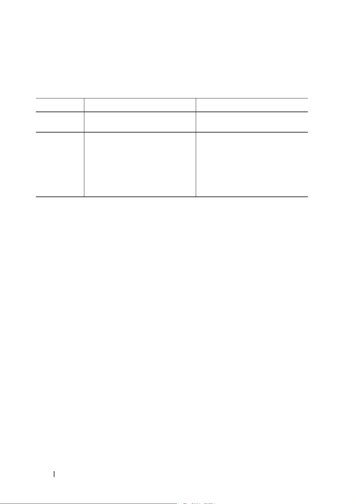
表 1-1 說明 N3024EP-ON 及 N3048EP-ON PoE 交換器的耗電量。
表 1-1. N3024EP-ON/N3048EP-ON PoE 交換器耗電量
Model
N3024EP-ON/
N3048EP-ON
輸入電壓 電源組態 最大待機電流消
100V/60Hz PSU1 + PSU2 21.8 2180.0
110V/60Hz PSU1 + PSU2 19.5 2145.0
120V/60Hz PSU1 + PSU2 17.8 2136.0
220V/50Hz PSU1 + PSU2 9.31 2048.2
240V/50Hz PSU1 + PSU2 8.6 2064.0
耗量 (A)
最大待機電
源 (W)
入門指南 5
Page 6
如 表 1-2 所示,若交換器只配備一個 1100W 電源供應器,PoE 功率預算
為 950W;若交換器配備兩個 1100W 電源供應器,則為 1900W。
表 1-2. Dell EMC Networking N3024EP-ON PoE 功率預算限制
一個 PSU 兩個 PSU
機型名稱 最大 PSU 輸出
能力
Dell EMC
1100W
Networking
N3024EP-ON
Dell EMC
1100W
Networking
N3048EP-ON
PoE+ 功率
啟動限制
功率預算為 950W:
PoE 供應總功率不得
超過 950W。
功率預算為 950W:
PoE 供應總功率不得
超過 950W。
最大 PSU 輸出
能力
2200W
2200W
PoE+ 功率
啟動限制
功率預算為 1900W:
所有 PoE+ 連接埠皆
可提供最大功率。
功率預算為 1900W:
所有 PoE+ 連接埠皆
可提供最大功率。
通風系統
有兩個風扇可冷卻 N3000ET-ON/N3000EP-ON 交換器。交換器的每個內
部電源供應器中均額外內建一個風扇。
N3000ET-ON/N3000EP-ON 風扇是現場可更換單元 (FRU)。
6 入門指南
Page 7

N3000ET-ON/N3000EP-ON 機型摘要
表 1-3. N3000ET-ON/N3000EP-ON 交換式穩壓器編號
行銷機型名稱
(MMN)
說明 電源供應器
(PSU)
安規型號
(RMN)
安規類型號
碼 (RTN)
N3024EP-ON
N3024ET-ON
N3024EF-ON
N3048EP-ON
24 個 1G/2 個 1G 組合 /
2 個 10G SFP+/2 個堆疊 /
1 個模組化插槽 /
N+1 備援熱插拔 PSU/
24 個 PoE+ 連接埠 /
12 個 PoE 60W 輸出連接埠 /
1 個抽取式風扇模組
24 個 1G RJ-45/2 個 1G SFP 組合 /
2 個 10G SFP+/2 個堆疊 /
1 個模組化插槽 /
N+1 備援熱插拔 PSU/
1 個抽取式風扇模組
24 個 1G SFP/2 個 1G SFP 組合 /
2 個 10G SFP+/2 個堆疊 /
1 個模組化插槽 /
N+1 備援熱插拔 PSU/
1 個抽取式風扇模組
48 個 1G/2 個 1G 組合 /
2 個 10G SFP+/2 個堆疊
1 個模組化插槽 /
N+1 備援熱插拔 PSU/
PoE+ 48 個連接埠 /
PoE12 個 60W 輸出連接埠
1 個抽取式風扇模組
/
715W/1100W E06W E06W001
200W E07W E07W001
200W E07W E07W003
715W/1100W E06W E06W002
N3048ET-ON
48 個 1G RJ-45/2 個 1G 組合 /
2 個 10G SFP+/2 個堆疊 /
1 個模組化插槽 /
N+1 備援熱插拔 PSU/
1 個抽取式風扇模組
200W E07W E07W002
入門指南 7
Page 8
N3000ET-ON/N3000EP-ON 安裝
機架安裝 N3000ET-ON/N3000EP-ON 交換器
警告: 閱讀
換器的安全資訊。
交流電變壓器連接器位於交換器後面板。
安全安規資訊
中的安全資訊,以及連接或支援交換器的其他交
安裝在機架中
警告: 請勿使用機架安裝套件將交換器懸掛在桌下或書桌下,或將其附加
在牆上。
警示: 從交換器拔下所有纜線,然後再繼續。從電腦底部的交換器移除所
有自黏性橡膠墊 ( 如果使用者已經連接 )。
警示: 將多台交換器安裝至機架時,請由下而上安裝。
註 : 此安裝程序僅適用於兩柱式機架。
1
將隨附的機架安裝托架固定至交換器的一側,確實將機架安裝托架上
的三個梨形孔對齊機箱上的三個支柱。
圖 1-1 說明對齊托架與支柱的位置。
8 入門指南
Page 9

圖 1-1. 對齊托架
2
將機架安裝托架向後推,使托架固定至鎖定位置。
3
將機架安裝托架以同樣的流程安裝在交換器另一側。
4
將交換器連接至
48.26
公分
(19 吋)
的機架,確實將托架上的機架安裝
孔對齊機架中的安裝孔。
圖 1-2. 將托架固定至機架
5
使用機架螺栓或四角螺帽和四角螺栓 (搭配墊片) 將托架固定至機架
根據您的機架種類)。先鎖緊螺栓頂端,然後再鎖緊螺栓底部。
(
入門指南 9
Page 10

6
重複此程序,將托架固定至機架另一側。
註 : 請確定通風孔沒被擋住。
堆疊多台 N3000ET-ON/N3000EP-ON 交換器
您可以使用交換器背面的迷你 SAS 固定堆疊連接埠,堆疊最多 12 台
N3000ET-ON/N3000EP-ON 交換器。透過堆疊連接埠連接多台交換器時,
它們會以最多 576 個前面板連接埠的單一裝置形式運作。堆疊會作為單一
實體運作並受管理。如需更多相關資訊,可參考
參考指南
。
使用者設定指南和 CLI
10 入門指南
Page 11

啟動和設定 N3000ET-ON/ N3000EP-ON 交換器
以下流程圖會說明從包裝中取出交換器並安裝完成後,執行初始設定所需
的步驟。
圖 1-3. 安裝與設定流程圖
入門指南 11
Page 12

將 N3000ET-ON/N3000EP-ON 交換器連接至終 端機
完成所有外部連接後,連接至終端機,進行交換器設定。
註 : 在進行組態前,請閱讀本產品的發行說明。您可在 Dell 支援網站:
dell.com/support 上下載發行說明。
註 : Dell 建議透過 Dell 支援網站 dell.com/support 取得最新版本的使用者文
件。
若要透過 USB 主控台監控和設定,請使用交換器前面板上的主控台連接
埠,利用提供的 USB 纜線將主控台連接至執行 VT100 終端機模擬軟體的
電腦。初次使用 USB 纜線時,可能需要下載並安裝驅動程式。
使用主控台連接埠需要下列裝置:
•
具有
•
USB
例如 HyperTerminal®) 和 USB 隨身碟。
(
提供的
連接埠且執行
USB
纜線附用於主控台連接埠 的
VT100
終端機模擬程式、相容
Type-B USB
連接器,和用於
VT100
的電腦
主機個人電腦的
執行下列工作,以將終端機連接至交換器主控台連接埠:
1
連接所提供的交換器上的
VT100
行
2
按以下步驟設定終端機模擬軟體:
a
選擇正確的序列埠 (例如
b
將資料速率設定為
c
設定資料格式為
d
設定流量控制為
e
設定終端機模擬模式為 VT100
f
選擇功能、方向鍵和
鍵
3
將纜線上的
Dell EMC Networking
終端機模擬軟體的電腦。
(
而非
USB
Microsoft Windows 鍵)
USB Type-B
連接器。
USB Type-B
COM 1)
115,200
8 data bits、1 stop bit
none
。
Ctrl
連接器直接連接到交換器主控台連接埠。
主控台連接埠位於前面板的右側,使用 |O|O|
傳輸速率。
鍵的終端機鍵。確保該設定適合終端機
連接器,並將另外一頭連接至執
以連接至主控台。
以及
no parity
。
。
。
符號標記。
註 : 主控台存取堆疊管理程式,可透過本機 CLI 主控台連接埠進入。
同一時間內只能進行一組 USB 主控台工作階段。
12 入門指南
Page 13

N3000ET-ON/N3000EP-ON 將 交換器連接至電源
警示: 閱讀
他交換器的安全資訊。
N3000ET-ON/N3000EP-ON 交換器支援一或兩個 FRU 電源供應器。 電源
插座位於後面板上。
安全安規資訊手冊
中的安全資訊,以及連接或支援交換器的其
交流電和直流電源連接
1
請確保交換器主控台連接埠已經透過
VT100
2
使用附有槽口連接器
安全接地的標準電源線
器上的
3
將電源線連接至接地交流電插座。
終端機模擬器的個人電腦。
AC
(PoE
主插座。
模組) 的
(非 PoE
USB 對 USB
1.5m (5 呎)
模組),將電源線連接至後方電源供應
纜線連接至執行
高功率電源線,或已
入門指南 13
Page 14

啟動 N3000ET-ON/N3000EP-ON 交換器
若電源開啟,且已連接本機終端機,則交換器將進行開機自我測試
(POST)。交換器每次初始化並檢查硬體元件後,都會運行開機自我測
試,確保交換器在完全啟動前完全處於全面運作狀態。若開機自我測試檢
測出嚴重問題,則程式流程將停止。若成功通過開機自我測試,則有效的
硬體將會載入至 RAM。開機自我測試資訊會在終端機上顯示是否通過測
試。開機程式執行時間約為 60 秒。
可以在開機自我測試完成第一部分後,啟動 boot ( 開機 ) 功能表。透過
Boot ( 開機 ) 功能表,您可以執行設定工作,例如將系統重設為原廠設
定、啟動備份影像,或復原密碼。有關 Boot ( 開機 ) 功能表的更多資訊,
請參考
CLI 參考指南
。
14 入門指南
Page 15

進行 N3000ET-ON/N3000EP-ON 的初始設定
初始設定程序以下列假設為依據:
• Dell EMC Networking
• Dell EMC Networking
•
已建立主控台連接,
機模擬軟體的個人電腦畫面上。
初始交換器設定係透過主控台連接埠執行。初始設定完成後,您可透過已
連接的主控台連接埠或於初始設定期間定義的介面來管理交換器。
註 : 交換器未使用預設使用者名稱、密碼或 IP 位址設定。
完成交換器初始設定後,請從網路管理員處取得以下資訊:
•
要指派給管理介面的
•
網路
IP
子網路遮罩。
•
管理介面預設閘道的
這些設定有必要透過 Telnet (Telnet 客戶端 ) 或 HTTP ( 網頁瀏覽器 ) 進行
遠端管理。
之前未設定過交換器。
交換器成功啟動。
Dell EMC
IP
位址。
IP
位址。
簡易安裝精靈 提示會出現在執行終端
啟動遠端管理
N3000ET-ON/N3000EP-ON 交換器的前面板備有 Gigabit 乙太網路連接
埠,用於進行頻外 (OOB) 管理。OOB 連接埠位於主控台連接埠右側。在
N3000ET-ON/N3000EP-ON 交換器上,您可以另外使用前面板的任意交換
器連接埠來執行頻內管理。所有頻內連接埠均預設位於 VLAN 1。
Dell EMC 簡易安裝精靈 包含設定網路資訊的提示,可供設定
N3000ET-ON/N3000EP-ON 交換器上的 OOB 管理介面和 VLAN 1 介面。
您可指定靜態 IP 位址和子網路遮罩或啟動 DHCP,允許網路 DHCP 伺服
器指派資訊。
關於網路資訊設定方面的指令,請參考
CLI 參考指南
。
入門指南 15
Page 16

初始設定程式
使用 Dell EMC 簡易安裝精靈 或 CLI 執行初始設定。交換器設定檔清空
時,精靈將自動啟動。按下 [ctrl+z] 可隨時退出精靈,但是所有指定組態
設定將被刪除,交換器會使用預設值。
註 : 若不運行 Dell EMC 簡易安裝精靈 或者未在 60 秒內對初始簡易安裝精靈
提示進行回應,則交換器將進入 CLI 模式。為重新啟動 Dell EMC 簡易安裝精
靈,必須透過清空啟動組態重設交換器。
透過 CLI 執行初始設定的更多相關資訊,可參考
將說明如何使用 Dell EMC 簡易安裝精靈 完成初始交換器組態。安裝
指南
CLI 參考指南
精靈會設定交換器組態如下:
•
使用有效密碼建立初始有權限的使用者帳戶。精靈在設定期間,會設
定一個有權限的使用者帳戶。
•
啟動
CLI
•
設定
OOB
•
設定
VLAN1
•
在指定
SNMP
•
讓您可指定網路管理系統
•
為
VLAN1
登入和
HTTP
管理介面的
路由介面的
IP
位址上設定用於
管理不適用於本交換器,請跳過此步驟。
介面設定預設閘道
存取,僅使用本機驗證設定。
IP
位址。
IP
位址,其包括所有頻內連接埠。
SNMP
管理器的
SNMP
社群字串。若
IP
位址或允許所有
IP
位址。
IP
位址的管理存取。
。本
入門
16 入門指南
Page 17

範例工作階段
本節說明 Dell EMC 簡易安裝精靈的工作階段。範例工作階段使用以
下值:
•SNMP
•
網路管理系統
•
使用者名稱為 admin
•OOB
• VLAN 1
255.255.255.0
•
預設閘道為 10.1.1.1.
社群字串可 public (公開) 使用。
(NMS) IP
位址為 10.1.2.100
,密碼為 admin123
管理介面會使用 DHCP 來指派
路由介面的
IP
位址為 10.1.1.200
IP
。
。
。
位址。
,子網路遮罩為
安裝精靈設定的初始值如上所示。在完成精靈後,交換器的設定如下:
•
啟動
SNMPv2
•
根據要求設定管理使用者帳戶。
•
網路管理系統已設定。可透過管理站進入
面。您也可以選擇
,社群字串設定如上文所述。
SNMP、HTTP 及 CLI
(0.0.0.0) IP
位址,允許所有
SNMPv3
IP
位址存取這些管理
預設為停用。
介
介面。
•OOB
管理介面已啟用
DHCP
。
•
設定
VLAN1
•
預設閘道位址已設定。
註 : 下列範例中,可能的使用者選項或預設值包含在 [ ] 中。若您按下
<Enter> 而未定義其他選項,則會接受預設值。協助文字位於括號中。
路由介面的
IP
位址。
入門指南 17
Page 18

Dell EMC 簡易安裝精靈 主控台的範例。
下列範例包含有關範例 Dell EMC 簡易安裝精靈 工作階段的提示順序和
回應,該階段使用的是先前列出的輸入值。
在交換器完成開機自我測試並啟動後,將出現以下對話:
Unit 1 - Waiting to select management unit)>
___________Dell SupportAssist EULA__________________
I accept the terms of the license agreement. You can
reject the license agreement by configuring this
command 'eula-consent support-assist reject'.
By installing SupportAssist, you allow Dell to save
your contact information (e.g. name, phone number
and/or email address) which would be used to provide
technical support for your Dell products and services
Dell may use the information for providing
recommendations to improve your IT infrastructure.
Dell SupportAssist also collects and stores machine
diagnostic information, which may include but is not
limited to configuration information, user supplied
contact information, names of data volumes, IP
addresses, access control lists, diagnostics &
performance information, network configuration
information, host/server configuration & performance
information and related data (Collected Data) and
transmits this information to Dell. By downloading
SupportAssist and agreeing to be bound by these terms
and the Dell end user license agreement, available at:
http://www.dell.com/aeula, you agree to allow Dell to
provide remote monitoring services of your IT
environment and you give Dell the right to collect the
Collected Data in accordance with Dell's Privacy
Policy, available at:
http://www.dell.com/privacypolicycountryspecific, in
order to enable the performance of all of the various
functions of SupportAssist during your entitlement to
18 入門指南
Page 19

receive related repair services from Dell. You further
agree to allow Dell to transmit and store the
Collected Data from SupportAssist in accordance with
these terms. You agree that the provision of
SupportAssist may involve international transfers of
data from you to Dell and/or to Dell's affiliates,
subcontractors or business partners. When making such
transfers, Dell shall ensure appropriate protection is
in place to safeguard the Collected Data being
transferred in connection with SupportAssist. If you
are downloading SupportAssist on behalf of a company
or other legal entity, you are further certifying to
Dell that you have appropriate authority to provide
this consent on behalf of that entity. If you do not
consent to the collection, transmission and/or use of
the Collected Data, you may not download, install or
otherwise use SupportAssist.
________AeroHive HiveManager NG EULA________________
This switch includes a feature that enables it to work
with HiveManager (an optional management suite), by
sending the switch's service tag number and IP Address
to HiveManager to authenticate your entitlement to use
HiveManager. If you wish to disable this feature, you
should run command 'eula-consent hiveagent reject'
immediately upon powering up the switch for the first
time, or at any time thereafter.
Applying Global configuration, please wait...
Welcome to Dell Easy Setup Wizard
The setup wizard guides you through the initial switch
configuration, and gets you up and running as quickly
as possible. You can skip the setup wizard, and enter
CLI mode to manually configure the switch. You must
respond to the next question to run the setup wizard
within 60 seconds, otherwise the system will continue
入門指南 19
Page 20

with normal operation using the default system
configuration. Note: You can exit the setup wizard at
any point by entering [ctrl+z].
Would you like to run the setup wizard (you must
answer this question within 60 seconds)? [Y/N] y
Step 1:
The system is not set up for SNMP management by
default. To manage the switch using SNMP (required for
Dell Network Manager) you can
. Set up the initial SNMP version 2 account now.
. Return later and set up other SNMP accounts. (For
more information on setting up an SNMP version 1 or
3 account, see the user documentation).
Would you like to set up the SNMP management interface
now? [Y/N] y
To set up the SNMP management account you must specify
the management system IP address and the “community
string” or password that the particular management
system uses to access the switch. The wizard
automatically assigns the highest access level
[Privilege Level 15] to this account. You can use Dell
Network Manager or other management interfaces to
change this setting, and to add additional management
system information later. For more information on
adding management systems, see the user documentation.
To add a management station:
Please enter the SNMP community string to be used.
[public]: public
註 : 若已完成設定,預設存取級別會被設定為 SNMP 管理介面的最高可用存
取。一開始只會啟動 SNMPv2。SNMPv3 會被禁用,直到您返回 SNMPv3 安
全性存取 ( 例如:引擎 ID、視圖 … 等 ) 為止。
20 入門指南
Page 21

Please enter the IP address of the Management System
(A.B.C.D) or wildcard (0.0.0.0) to manage from any
Management Station. [0.0.0.0]: 10.1.2.100
Step 2:
Now we need to set up your initial privilege (Level 15)
user account. This account is used to login to the CLI
and Web interface. You may set up other accounts and
change privilege levels later. For more information on
setting up user accounts and changing privilege
levels, see the user documentation.
To set up a user account:
Please enter the user name. [root]:admin
Please enter the user password: ********
Please reenter the user password: ********
Step 3:
Next, an IP address is set up on the VLAN 1 routing
interface.
You can use the IP address to access the CLI, Web
interface, or SNMP interface of the switch.
To access the switch through any Management Interface
you can
. Set up the IP address for the Management Interface.
. Set up the default gateway if IP address is
manually configured on the routing interface.
Would you like to set up the Out-Of-Band interface
now? [Y/N] y
Please enter the IP address of the device (A.B.C.D) or
enter “DHCP” (without the quotes) to automatically
request an IP address from the network DHCP server.
[192.168.2.1]: dhcp
入門指南 21
Page 22

Step 4:
Would you like to set up the VLAN1 routing interface
now? [Y/N] y
Please enter the IP address of the device (A.B.C.D) or
enter “DHCP” (without the quotes) to automatically
request an IP address from the network DHCP server:
10.1.1.200
Please enter the IP subnet mask (A.B.C.D or /nn):
255.255.255.0
Step 5:
Finally, set up the default gateway. Please enter the
IP address of the gateway from which this network is
reachable. [0.0.0.0]: 10.1.1.1
This is the configuration information that has been
collected:
SNMP Interface = “public”@10.1.2.100
User Account setup = admin
Password = ********
VLAN1 Router Interface IP = 10.1.1.200 255.255.255.0
Default Gateway = 10.1.1.1
Step 6:
If the information is correct, please enter (Y) to
save the configuration and copy the settings to the
start-up configuration file. If the information is
incorrect, enter (N) to discard the configuration and
restart the wizard: [Y/N] y
Thank you for using the Dell Easy Setup Wizard. You
will now enter CLI mode.
Applying Interface configuration, please wait...
22 入門指南
Page 23

下一步
完成本節所述的初始組態設定後,您可以將 OOB 連接埠連接至管理網路
以進行頻外遠端管理,亦可將任意前面板交換器連接埠連接至生產網路來
進行頻內遠端管理。
如果為 OOB 介面或為 VLAN 1 管理介面 IP 位址指定了 DHCP,介面將從
網路的 DHCP 伺服器上取得 IP 位址。為了尋找動態指派 IP 位址,請使
用主控台連接埠連接裝置發出下列命令:
•
若為
OOB
頻外
•
針對
若要存取 Dell OpenManage Switch Administrator 介面,請在網頁瀏覽器
的網址欄位中輸入 OOB 管理介面 IP 位址,或是輸入 VLAN 1 管理介面 IP
位址。若要透過遠端管理存取 CLI,可在 Telne t 或 SSH 用戶端中輸入
OOB 管理介面 IP 位址或 VLAN 1 管理介面 IP 位址。或者,繼續使用本機
CLI 的主控台連接埠存取交換器。
N3000ET-ON/N3000EP-ON 交換器支援基本的交換功能,例如 VLAN 和
)
VLAN 1
介面,請輸入 show ip interface out-of-band (顯示
。
路由介面,輸入
show ip interface (顯示介面)。
IP
介面
擴充樹通訊協定。使用網路管理介面或 CLI 設定您的網路所需的功能。
如需有關如何設定交換器功能的資訊,請參考
考指南
,其可於支援網站上取得:dell.com/support。
使用者組態指南或 CLI 參
入門指南 23
Page 24

操作高度 – 資訊更新
註 : 本文件內提供的操作高度限制僅適用於出貨至中國的系統。
下列資訊符合中國官方標準的要求:
•
作業海拔高度範圍
•
如高度超過
2,950
–15.2m 至 2,000m (–50ft 至 6,560ft)
呎,則最大作業溫度降低為
1°F/550
。
呎。
24 入門指南
Page 25

www.dell.com | dell.com/support
 Loading...