

Dell EMC PowerEdge T440 Installation And Service Manual

Dell EMC PowerEdge T440
Installation and Service Manual
Regulatory Model: E30S Series
Regulatory Type: E30S002

Notes, cautions, and warnings
NOTE: A NOTE indicates important information that helps you make better use of your product.
CAUTION: A CAUTION indicates either potential damage to hardware or loss of data and tells you how to avoid the problem.
WARNING: A WARNING indicates a potential for property damage, personal injury, or death.
Copyright © 2017 Dell Inc. or its subsidiaries. All rights reserved. Dell, EMC, and other trademarks are trademarks of Dell Inc. or its subsidiaries. Other
trademarks may be trademarks of their respective owners.
2017 - 09
Rev. A00

Contents
1 Dell EMC PowerEdge T440 overview............................................................................................................. 8
Supported congurations for the PowerEdge T440 system........................................................................................ 8
Front view of the system.................................................................................................................................................10
Status LED indicators.................................................................................................................................................14
System health and system ID indicator codes........................................................................................................ 16
Drive indicator codes..................................................................................................................................................17
Back view of the system..................................................................................................................................................18
NIC indicator codes....................................................................................................................................................19
Power supply unit indicator codes...........................................................................................................................20
2 Diagnostic indicators....................................................................................................................................22
Diagnostics and indicators.............................................................................................................................................. 22
Status LED indicators................................................................................................................................................ 22
System health and system ID indicator codes........................................................................................................23
Drive indicator codes.................................................................................................................................................24
Power supply unit indicator codes...........................................................................................................................25
NIC indicator codes................................................................................................................................................... 26
Enhanced Preboot System Assessment.................................................................................................................26
Locating the Service Tag of your system......................................................................................................................28
3 Documentation resources............................................................................................................................ 30
4 Technical specications............................................................................................................................... 32
System dimensions.......................................................................................................................................................... 33
Chassis weight................................................................................................................................................................. 34
Processor specications................................................................................................................................................. 34
PSU specications...........................................................................................................................................................34
System battery specications........................................................................................................................................ 34
Expansion bus specications..........................................................................................................................................34
Storage controller specications....................................................................................................................................34
Drive specications..........................................................................................................................................................35
Drives...........................................................................................................................................................................35
Optical drive................................................................................................................................................................35
Ports and connectors specications............................................................................................................................. 35
USB ports................................................................................................................................................................... 35
NIC ports.....................................................................................................................................................................35
VGA ports................................................................................................................................................................... 35
Serial connector.........................................................................................................................................................35
Internal Dual microSD Module or vFlash card........................................................................................................ 36
Video specications.........................................................................................................................................................36
Environmental specications..........................................................................................................................................36
Standard operating temperature..............................................................................................................................37
Dell EMC PowerEdge T440 Installation and Service Manual
Contents
3

Expanded operating temperature............................................................................................................................ 38
Expanded operating temperature restrictions........................................................................................................38
Particulate and gaseous contamination specications..........................................................................................38
5 Initial system setup and conguration..........................................................................................................40
Setting up your system...................................................................................................................................................40
iDRAC conguration........................................................................................................................................................40
Options to set up iDRAC IP address........................................................................................................................40
Log in to iDRAC...........................................................................................................................................................41
Options to install the operating system......................................................................................................................... 41
Methods to download rmware and drivers............................................................................................................41
Downloading drivers and rmware.......................................................................................................................... 42
6 Pre-operating system management applications..........................................................................................43
Options to manage the pre-operating system applications........................................................................................43
System Setup...................................................................................................................................................................43
Viewing System Setup.............................................................................................................................................. 44
System Setup details.................................................................................................................................................44
System BIOS.............................................................................................................................................................. 45
iDRAC Settings utility................................................................................................................................................65
Device Settings..........................................................................................................................................................66
Dell Lifecycle Controller...................................................................................................................................................66
Embedded system management............................................................................................................................. 66
Boot Manager.................................................................................................................................................................. 66
Viewing Boot Manager..............................................................................................................................................66
Boot Manager main menu.........................................................................................................................................67
One-shot BIOS boot menu....................................................................................................................................... 67
System Utilities...........................................................................................................................................................67
PXE boot...........................................................................................................................................................................67
7 Installing and removing system components................................................................................................ 68
Safety instructions...........................................................................................................................................................68
Before working inside your system................................................................................................................................68
After working inside your system...................................................................................................................................68
Optional front bezel......................................................................................................................................................... 69
Removing the front bezel......................................................................................................................................... 69
Installing the front bezel............................................................................................................................................69
System feet.......................................................................................................................................................................70
Removing the system feet........................................................................................................................................70
Installing the system feet...........................................................................................................................................71
Caster wheels – optional.................................................................................................................................................72
Removing caster wheels........................................................................................................................................... 72
Installing caster wheels..............................................................................................................................................73
System cover....................................................................................................................................................................74
Removing the system cover..................................................................................................................................... 74
Installing the system cover....................................................................................................................................... 75
Dell EMC PowerEdge T440 Installation and Service Manual
4
Contents

Air shroud..........................................................................................................................................................................76
Removing the air shroud...........................................................................................................................................76
Installing the air shroud..............................................................................................................................................77
Drives.................................................................................................................................................................................78
Removing a drive blank............................................................................................................................................. 78
Installing a drive blank................................................................................................................................................79
Removing a drive carrier...........................................................................................................................................80
Installing a drive carrier.............................................................................................................................................. 81
Removing the drive from the drive carrier..............................................................................................................82
Installing a drive into the drive carrier......................................................................................................................83
Removing a 2.5 inch drive from a 3.5 inch drive adapter......................................................................................84
Installing a 2.5 inch drive into a 3.5 inch drive adapter..........................................................................................85
Removing a 3.5 inch drive adapter from a 3.5 inch drive carrier......................................................................... 86
Installing a 3.5 inch drive adapter into the 3.5 inch drive carrier..........................................................................87
Optical drives and tape drives........................................................................................................................................88
Removing the optical or tape drive blank............................................................................................................... 88
Installing the optical or tape drive blank..................................................................................................................89
Removing the optical drive cage or tape drive...................................................................................................... 90
Installing the optical drive cage or tape drive..........................................................................................................91
Cabled drives....................................................................................................................................................................92
Removing the internal hard drive bay......................................................................................................................92
Installing the internal hard drive bay........................................................................................................................ 93
Removing a cabled drive...........................................................................................................................................94
Installing a cabled drive............................................................................................................................................. 95
Drive backplane................................................................................................................................................................96
Removing a hard drive backplane............................................................................................................................98
Installing a hard drive backplane.............................................................................................................................. 99
Backplane cabling......................................................................................................................................................101
System memory..............................................................................................................................................................104
Removing a memory module.................................................................................................................................. 106
Installing a memory module..................................................................................................................................... 107
Cooling fans.................................................................................................................................................................... 108
Removing the internal cooling fan..........................................................................................................................108
Installing the internal cooling fan............................................................................................................................109
Removing the external cooling fan ........................................................................................................................ 110
Installing the external cooling fan.............................................................................................................................111
Optional internal USB memory key...............................................................................................................................112
Replacing optional internal USB memory key........................................................................................................ 112
Expansion card holder.....................................................................................................................................................113
Removing the expansion card holder......................................................................................................................113
Installing the expansion card holder........................................................................................................................114
Expansion cards...............................................................................................................................................................114
Expansion card installation guidelines.....................................................................................................................114
GPU card installation guidelines.............................................................................................................................. 116
Removing a expansion card.....................................................................................................................................116
Dell EMC PowerEdge T440 Installation and Service Manual
Contents
5

Installing an expansion card......................................................................................................................................117
Optional IDSDM or vFlash card.....................................................................................................................................119
Removing the MicroSD card....................................................................................................................................119
Installing the MicroSD card......................................................................................................................................119
Removing the optional IDSDM or vFlash card......................................................................................................120
Installing optional IDSDM or vFlash card...............................................................................................................120
Processors and heat sinks..............................................................................................................................................121
Removing a processor and heat sink module........................................................................................................122
Removing the processor from the processor and heat sink module..................................................................123
Installing the processor into a processor and heat sink module......................................................................... 125
Installing a processor and heat sink module..........................................................................................................128
Power supply units.........................................................................................................................................................129
Removing a power supply unit blank......................................................................................................................130
Installing a power supply unit blank........................................................................................................................130
Removing a power supply unit.................................................................................................................................131
Installing a power supply unit.................................................................................................................................. 132
Removing a cabled power supply unit................................................................................................................... 132
Installing a cabled power supply unit......................................................................................................................133
Power interposer board................................................................................................................................................. 134
Removing the power interposer board.................................................................................................................. 134
Installing the power interposer board.....................................................................................................................135
System battery............................................................................................................................................................... 136
Replacing the system battery................................................................................................................................. 136
Control panel assembly..................................................................................................................................................137
Removing the control panel assembly....................................................................................................................137
Installing the control panel assembly......................................................................................................................138
System board..................................................................................................................................................................140
Removing the system board................................................................................................................................... 140
Installing the system board......................................................................................................................................142
Entering the system Service Tag by using System Setup...................................................................................144
Restoring the Service Tag by using the Easy Restore feature............................................................................144
Trusted Platform Module...............................................................................................................................................144
Replacing the Trusted Platform Module................................................................................................................145
Initializing TPM for BitLocker users........................................................................................................................145
Initializing the TPM 1.2 for TXT users....................................................................................................................146
Converting the system from tower mode to rack mode...........................................................................................146
Converting the system from tower mode to rack mode ....................................................................................146
Updating BIOS................................................................................................................................................................ 147
Restoring the Service Tag using Easy Restore........................................................................................................... 147
Manually update the Service Tag........................................................................................................................... 148
8 Using system diagnostics........................................................................................................................... 149
Dell Embedded System Diagnostics.............................................................................................................................149
Running the Embedded System Diagnostics from Boot Manager.....................................................................149
Running the Embedded System Diagnostics from the Dell Lifecycle Controller..............................................149
System diagnostic controls..................................................................................................................................... 150
Dell EMC PowerEdge T440 Installation and Service Manual
6
Contents

9 Jumpers and connectors ............................................................................................................................151
Jumpers and connectors ...............................................................................................................................................151
System board jumper settings.................................................................................................................................151
Disabling forgotten password..................................................................................................................................152
System board jumpers and connectors.......................................................................................................................153
10 Getting help..............................................................................................................................................155
Contacting Dell............................................................................................................................................................... 155
Accessing system information by using QRL..............................................................................................................155
Quick Resource Locator for T440.......................................................................................................................... 156
Receiving automated support with SupportAssist ....................................................................................................156
Dell EMC PowerEdge T440 Installation and Service Manual
Contents
7

Dell EMC PowerEdge T440 overview
The PowerEdge T440 is a dual-socket, 5U rackable tower server that supports up to:
• Two Intel Xeon Scalable Processor Family processors
• Sixteen DIMM slots supporting up to a total of 16 x 64 GB = 1024GB of memory
• Five PCIe Gen 3 expansion cards, plus a dedicated PERC slot
• 4 or 8 x 3.5 inch SAS/SATA-hard drive or SSD, or 16 x 2.5 inch SAS/SATA drive bays (up to 12 Gbps SAS and 6 Gbps SATA)
• Redundant power supply units (PSUs)
• Cabled power supply units (PSUs)
Topics:
• Supported congurations for the PowerEdge T440 system
• Front view of the system
• Back view of the system
Supported congurations for the PowerEdge T440
1
system
The Dell EMC PowerEdge T440 system supports the following congurations:
8 Dell EMC PowerEdge T440 Installation and Service Manual
Dell EMC PowerEdge T440 overview
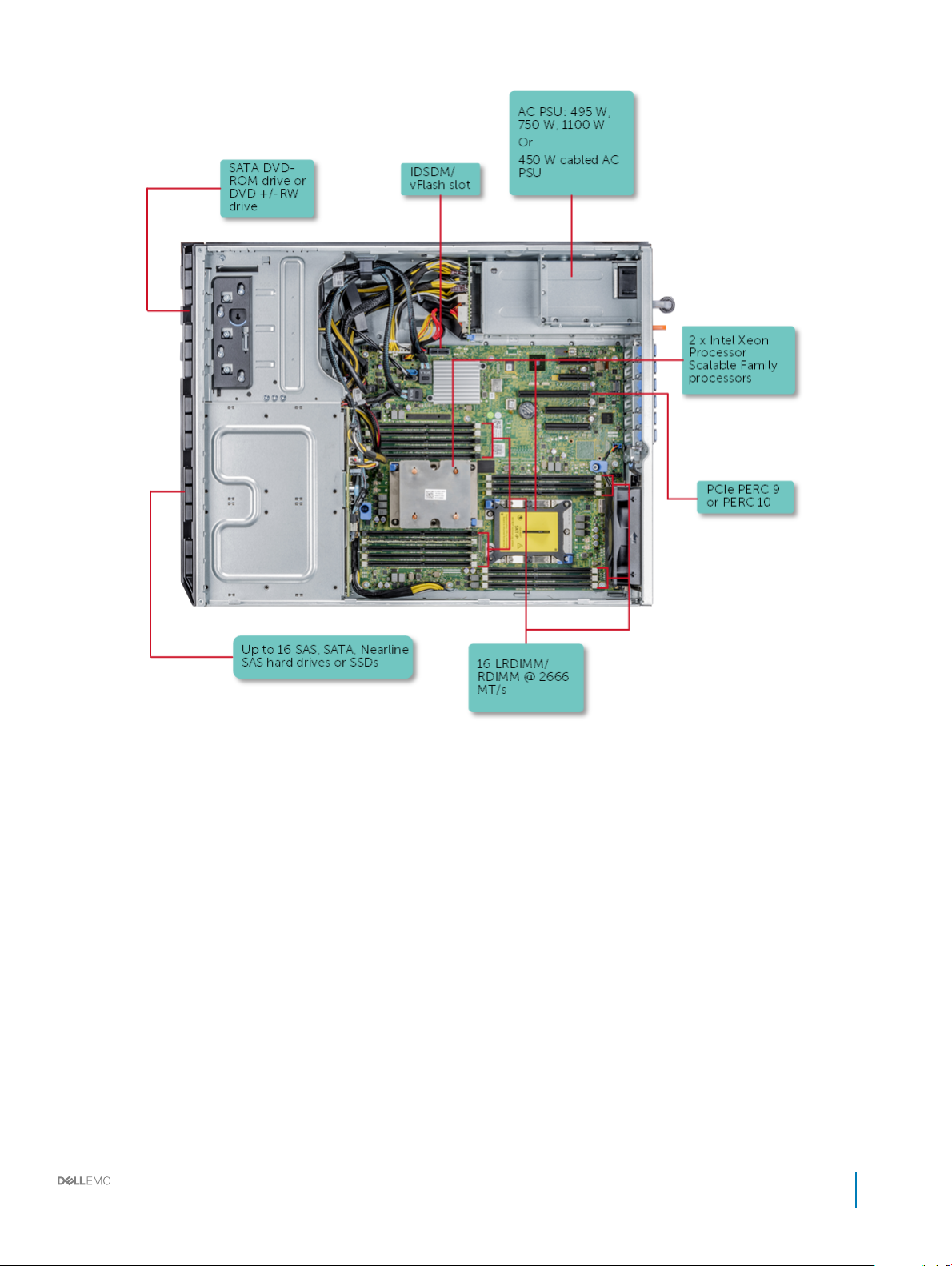
Figure 1. Supported congurations for a PowerEdge T440 system
Dell EMC PowerEdge T440 Installation and Service Manual
Dell EMC PowerEdge T440 overview
9
Front view of the system
The front panel view of the systems.
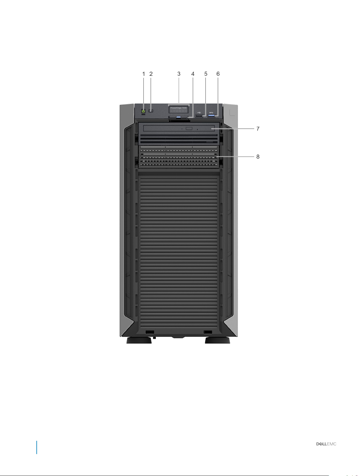
Figure 2. Front panel view of a 4 x 3.5 inch cabled drive system
10
Dell EMC PowerEdge T440 Installation and Service Manual
Dell EMC PowerEdge T440 overview
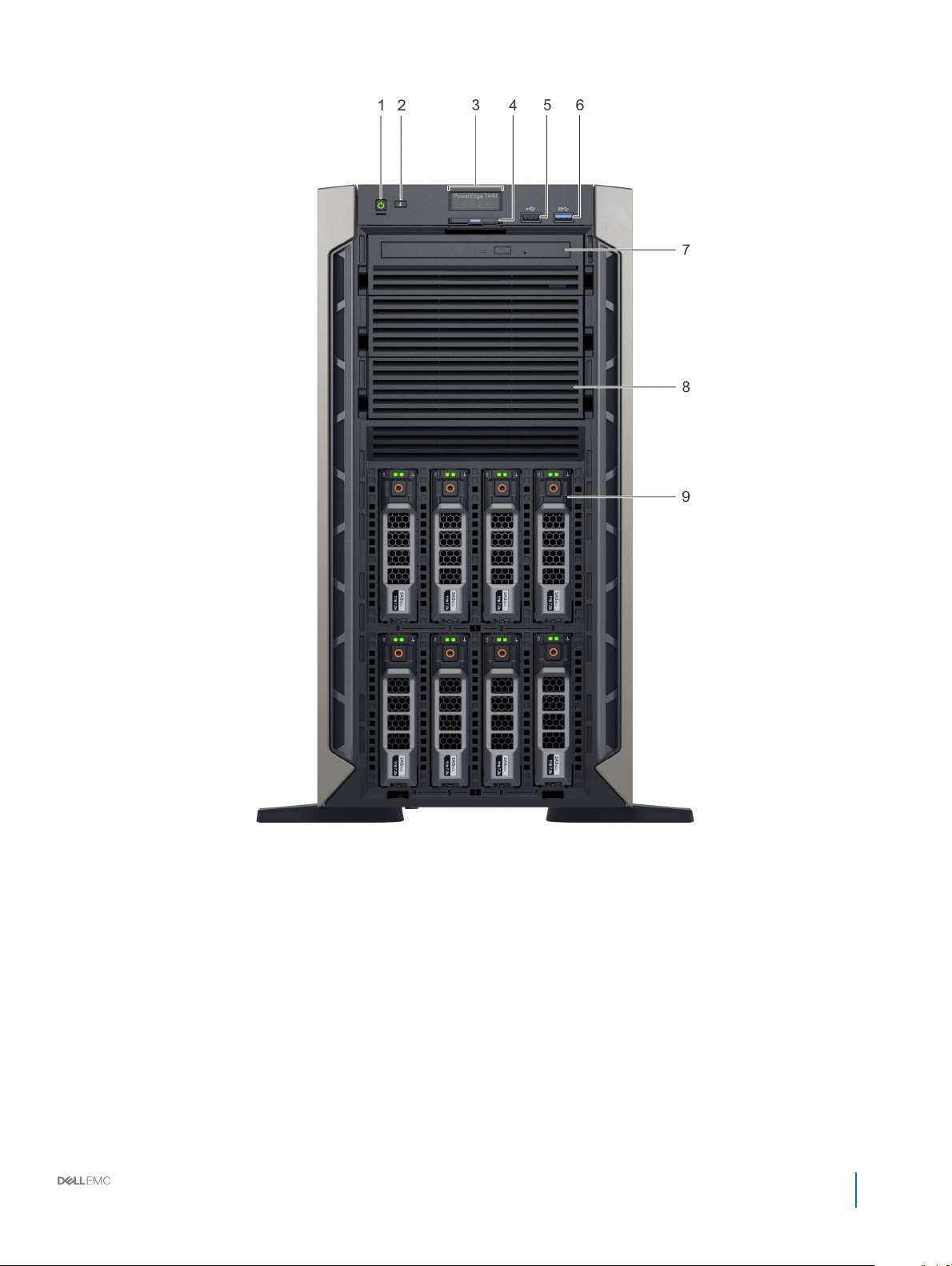
Figure 3. Front panel view of a 8 x 3.5-inch hot swappable drive system
Dell EMC PowerEdge T440 Installation and Service Manual
Dell EMC PowerEdge T440 overview
11
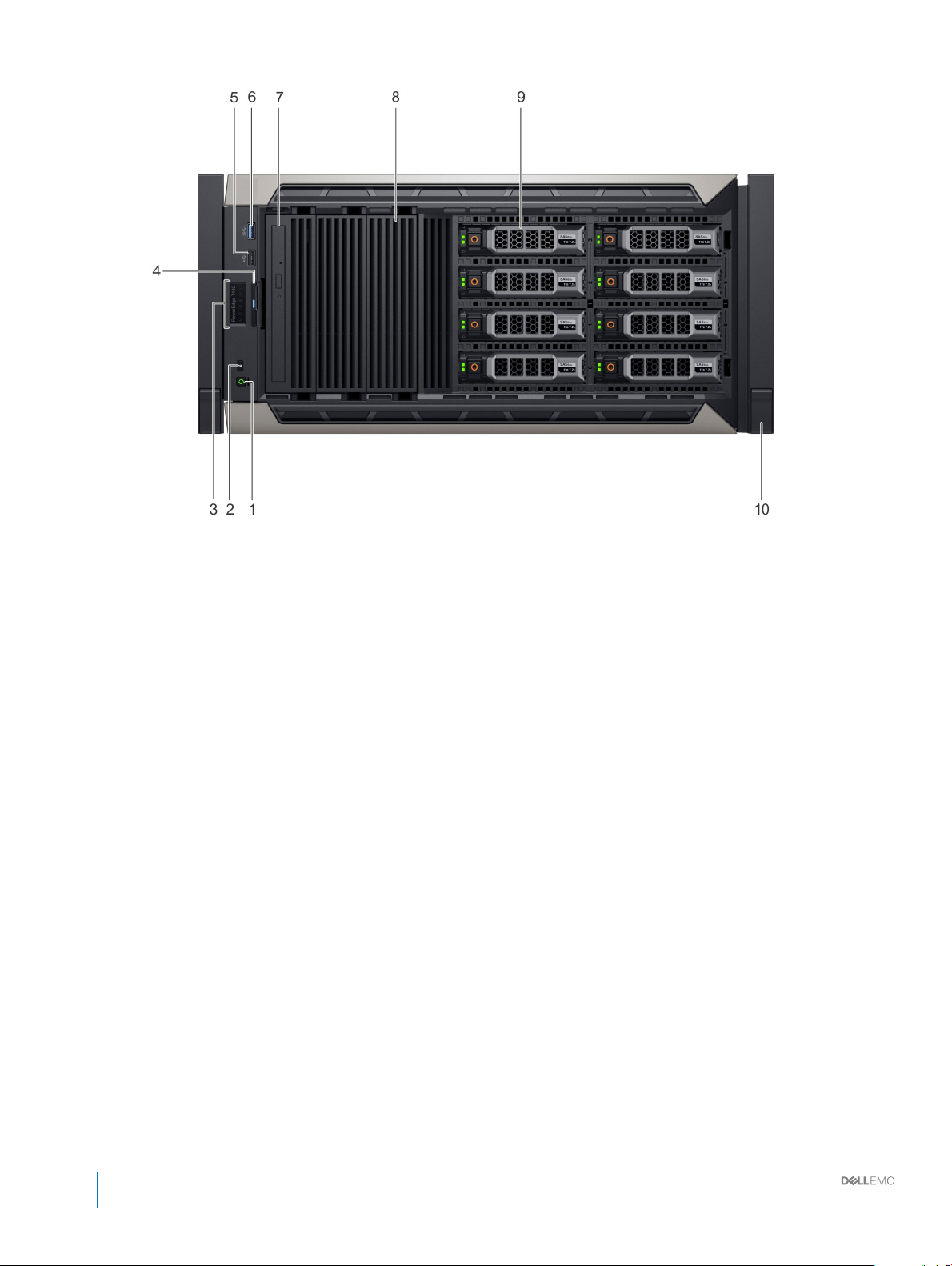
Figure 4. Front panel view of a 8 x 3.5-inch hot swappable drive system in rack mode
12
Dell EMC PowerEdge T440 Installation and Service Manual
Dell EMC PowerEdge T440 overview
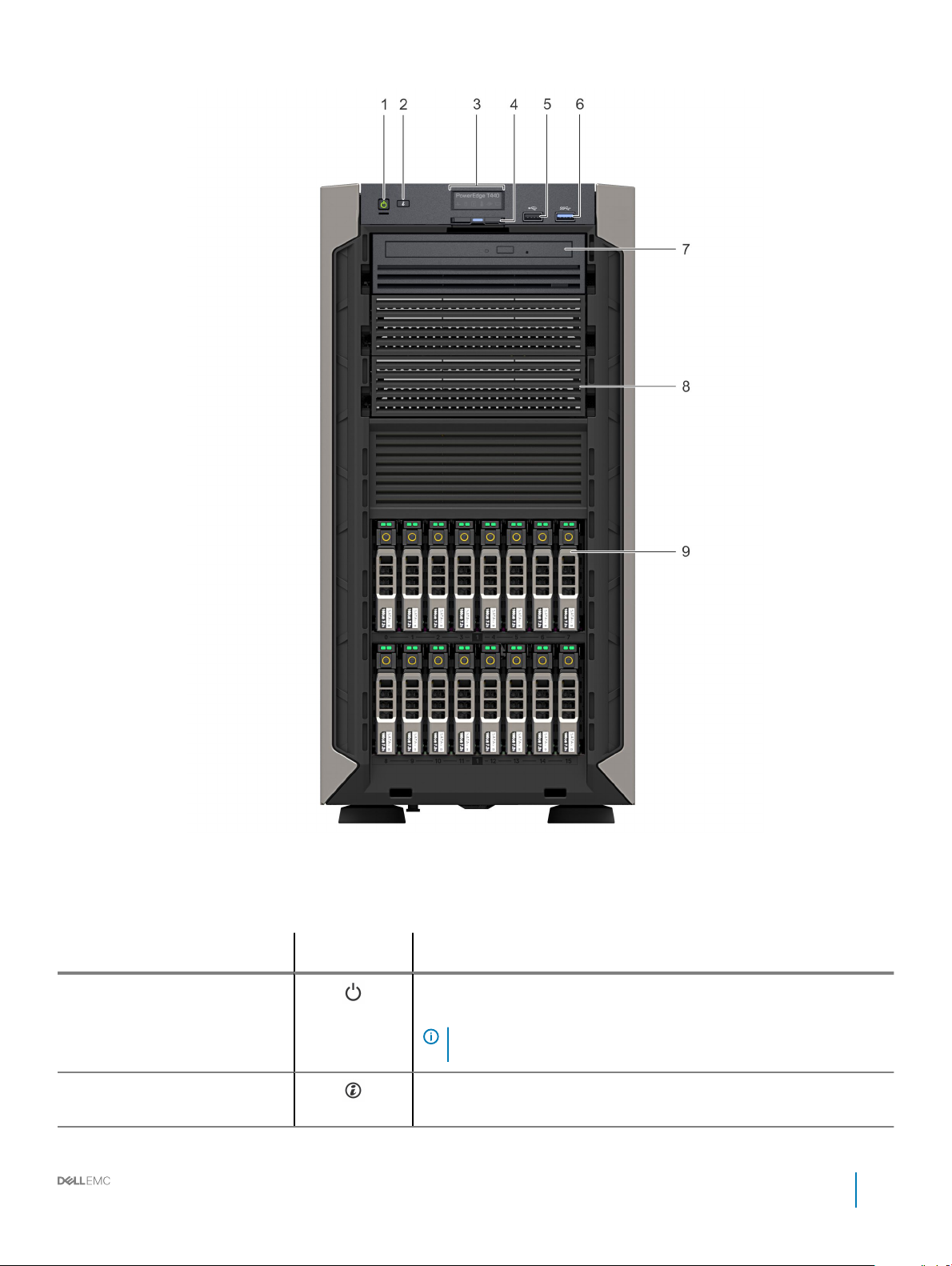
Figure 5. Front panel view of a 16 x 2.5-inch hot swappable drive system
Table 1. Front panel features
Item Components - Indicator,
Button, or Connector
1 Power button
2 System identication
button
Icon Description
Indicates if the system is turned on or o. Press the power button to manually
turn on or o the system.
NOTE: Press the power button to gracefully shut down an ACPI-
compliant operating system.
The System Identication (ID) button is available on the front and back of the
systems. Press the button to identify a system in a rack by turning on the
Dell EMC PowerEdge T440 Installation and Service Manual
Dell EMC PowerEdge T440 overview
13
Item Components - Indicator,
Button, or Connector
Icon Description
system ID button. You can also use the system ID button to reset iDRAC and
to access BIOS using the step through mode.
3 Status LED indicator panel N/A
4 Information tag N/A
5 USB port 2.0 The USB ports are 4-pin, 2.0-compliant. These ports enable you to connect
6 USB port 3.0 The USB port is USB 3.0 compliant.
7 Optical drive bay N/A
8 Drive slot NA Enables you to install TBUs for 8x and 16x backplane congurations, or drive
9 Physical drives NA 3.5 inch drives and 2.5 inch drives/SSDs.
10 Rack ear NA Enables you to convert the tower system to a rack system.
Related link
Status LED indicators
Technical specications
Indicate the status of the system. For more information, see the Status LED
indicators section.
The Information Tag is a slide-out label panel that contains system information
such as Service Tag, NIC, MAC address, and so on. If you have opted for
secure default access to iDRAC, the Information tag also contains the iDRAC
secure default password.
USB devices to the system.
Enable you to install drives that are supported on your system. For more
information about drives, see the Technical specications section.
blank in the empty drive slot to maintain proper system cooling.
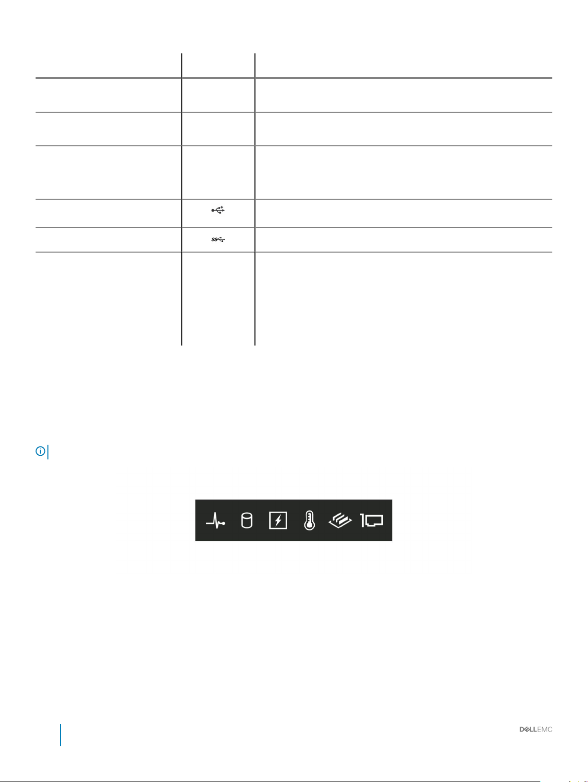
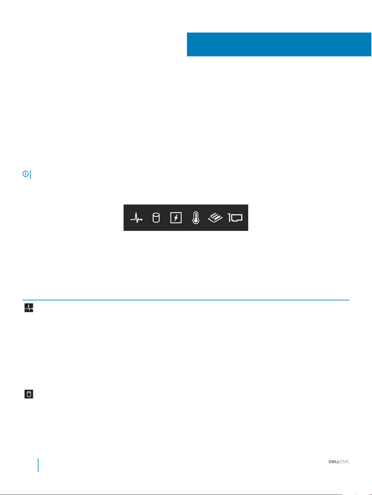
Status LED indicators
NOTE
: The indicators display solid amber if any error occurs.
Figure 6. Status LED indicators
14
Dell EMC PowerEdge T440 Installation and Service Manual
Dell EMC PowerEdge T440 overview

Table 2. Status LED indicators and descriptions
Icon Description Condition Corrective action
Health indicator The indicator turns solid blue if the
system is in good health.
None required.
The indicator blinks amber:
• When the system is turned on.
• When the system is in standby.
• If any error condition exists. For
example, a failed fan, PSU, or a
drive.
Drive indicator The indicator turns solid amber if
there is a drive error.
Electrical indicator The indicator turns solid amber if the
system experiences an electrical error
(for example, voltage out of range, or
a failed power supply unit (PSU) or
voltage regulator).
Temperature
indicator
The indicator turns solid amber if the
system experiences a thermal error
(for example, the ambient
temperature is out of range or there is
a fan failure).
Check the System Event Log or system messages for the
specic issue. For more information about error
messages, see the Dell Event and Error Messages
Reference Guide at Dell.com/openmanagemanuals >
OpenManage software.
The POST process is interrupted without any video
output due to invalid memory congurations. See the
Getting help section.
• Check the System Event Log to determine if the drive
has an error.
• Run the appropriate Online Diagnostics test. Restart
the system and run embedded diagnostics (ePSA).
• If the drives are congured in a RAID array, restart the
system, and enter the host adapter conguration
utility program.
Check the System Event Log or system messages for the
specic issue. If it is due to a problem with the PSU,
check the LED on the PSU. Reseat the PSU.
If the problem persists, see the Getting help section.
Ensure that none of the following conditions exist:
• A cooling fan has been removed or has failed.
• System cover, air shroud, memory module blank, or
back ller bracket is removed.
• Ambient temperature is too high.
• External airow is obstructed.
Memory indicator The indicator turns solid amber if a
PCIe indicator The indicator turns solid amber if a
Related link
Getting help
Expansion card installation guidelines
memory error occurs.
PCIe card experiences an error.
If the problem persists, see the Getting help section.
Check the System Event Log or system messages for the
location of the failed memory. Reseat the memory
module.
If the problem persists, see the Getting help section.
Restart the system. Update any required drivers for the
PCIe card. Reinstall the card.
If the problem persists, see the Getting help section.
NOTE: For more information about the
supported PCIe cards, see the Expansion card
installation guidelines section.
Dell EMC PowerEdge T440 Installation and Service Manual
Dell EMC PowerEdge T440 overview
15

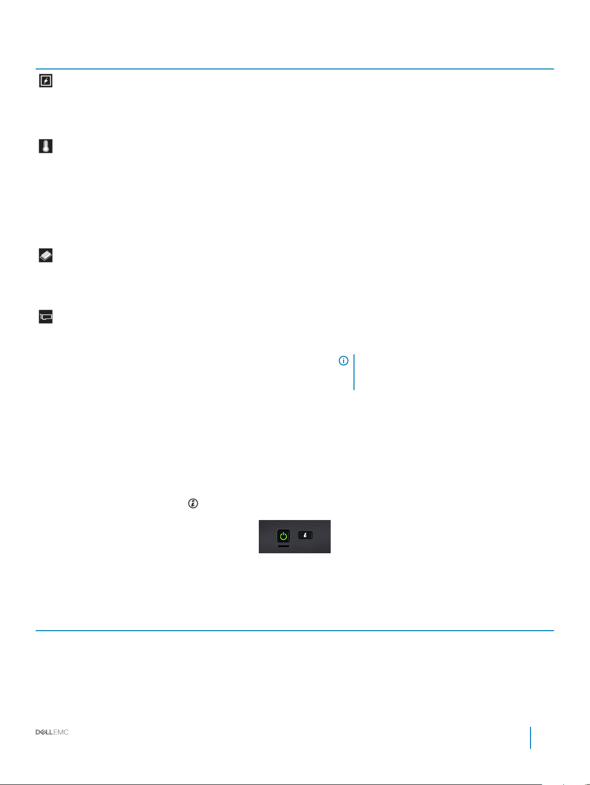
System health and system ID indicator codes
The system health and system ID button is located on the front panel of your system.
Figure 7. System health and system ID buttons
Table 3. System health and system ID indicator codes
System health and system ID indicator code Condition
Solid blue Indicates that the system is turned on, system is healthy, and system
ID mode is not active. Press the system health and system ID button
to switch to system ID mode.
Blinking blue Indicates that the system ID mode is active. Press the system health
and system ID button to switch to system health mode.
Solid amber Indicates that the system is in fail-safe mode. If the problem persists,
see the Getting help section.
Blinking amber Indicates that the system is experiencing a fault. Check the System
Event Log for specic error messages. For more information about
error messages, see the Dell Event and Error Messages Reference
Guide at Dell.com/openmanagemanuals > OpenManage software.
Related link
Getting help
16
Dell EMC PowerEdge T440 Installation and Service Manual
Dell EMC PowerEdge T440 overview
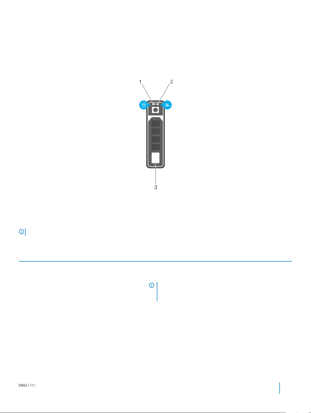
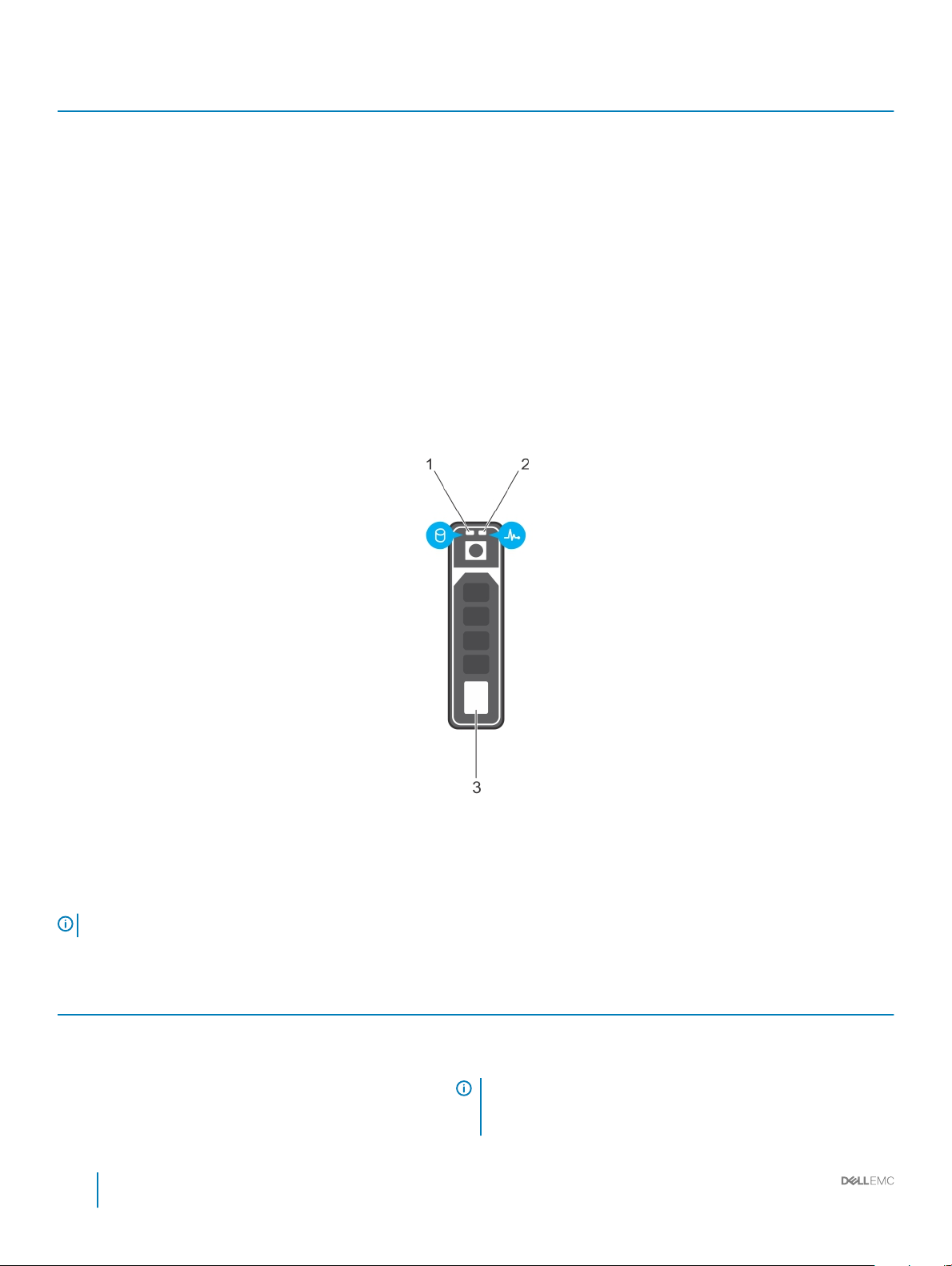
Drive indicator codes
Each drive carrier has an activity LED indicator and a status LED indicator. The indicators provide information about the current status of
the drive. The activity LED indicator indicates whether the drive is currently in use or not. The status LED indicator indicates the power
condition of the drive.
Figure 8. Drive indicators
1
Drive activity LED indicator 2 Drive status LED indicator
3 Drive
NOTE: If the drive is in the Advanced Host Controller Interface (AHCI) mode, the status LED indicator does not turn on.
Table 4. Drive indicator codes
Drive status indicator code Condition
Flashes green twice per second Identifying drive or preparing for removal.
O Drive ready for removal.
NOTE: The drive status indicator remains o until all drives are
initialized after the system is turned on. Drives are not ready
for removal during this time.
Flashes green, amber, and then turns o Predicted drive failure.
Flashes amber four times per second Drive failed.
Flashes green slowly Drive rebuilding.
Solid green Drive online.
Flashes green for three seconds, amber for three seconds, and
then turns o after six seconds
Rebuild stopped.
Dell EMC PowerEdge T440 Installation and Service Manual
Dell EMC PowerEdge T440 overview
17
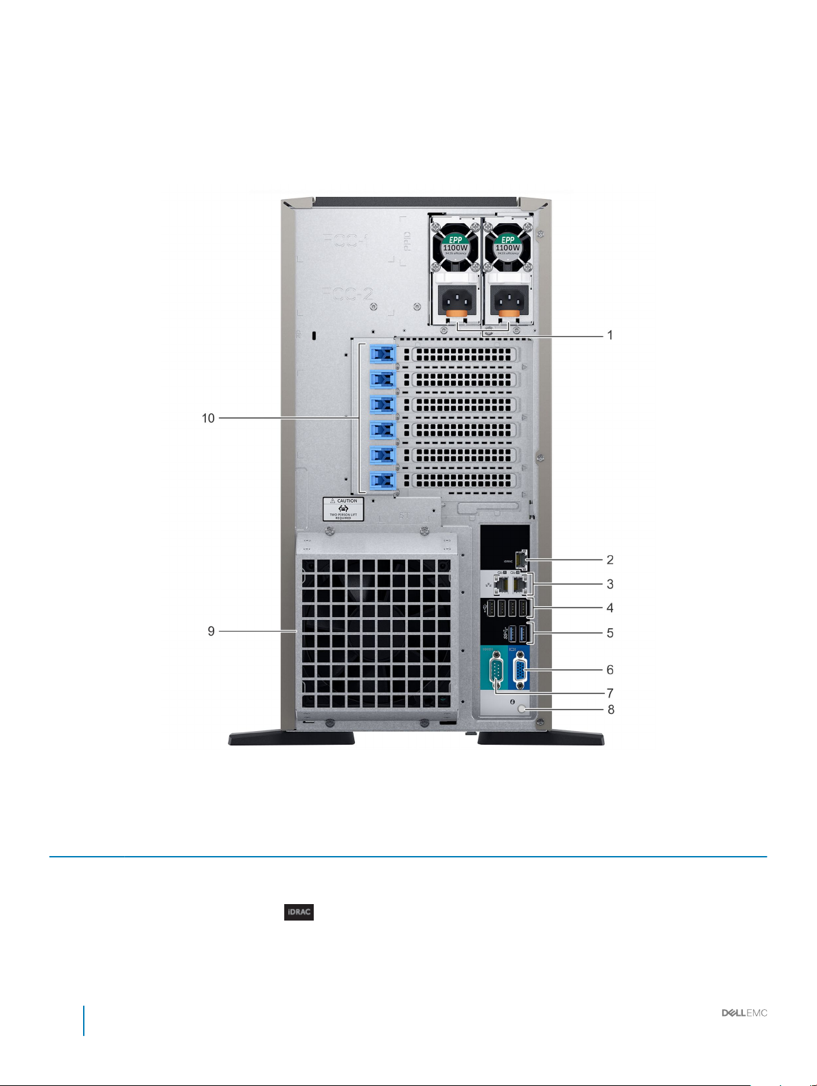
Back view of the system
The back panel view of the system shows the features available on the back of the server, such as the system identication button, power
supply sockets, iDRAC storage media, NIC ports, and USB and VGA ports. A majority of the expansion card ports can be accessed from the
back panel. The hot swappable and cabled power supply units are accessible from the back panel.
Figure 9. Back view of the system with optional redundant cooling fan
Table 5.
Item Ports, panels, or slots Icon Description
1 Power supply unit (2) N/A For more information about the PSU congurations, see the Technical
Specications section
2 iDRAC9 Enterprise port
18 Dell EMC PowerEdge T440 Installation and Service Manual
Dell EMC PowerEdge T440 overview
Enables you to remotely access iDRAC. For more information, see the
iDRAC User’s Guide at Dell.com/idracmanuals.
Item Ports, panels, or slots Icon Description
3 NIC port (2)
The NIC ports are integrated on the system board provide network
connectivity. For more information about the supported congurations,
see the Technical specications section.
4 USB 2.0 port (4)
5 USB 3.0 port (2)
6 VGA port
7 Serial port
8 System identication button
9 External cooling fan
(optional)
10 PCIe expansion card slot(6) N/A The expansion slot(s) enable you to connect PCI Express expansion
Related link
Technical specications
Expansion card installation guidelines
N/A Enables you to connect an optional redundant cooling fan.
The USB ports are 4-pin, 2.0-compliant. These ports enable you to
connect USB devices to the system.
The USB ports are 9-pin and 3.0-compliant. These ports enable you to
connect USB devices to the system.
Enables you to connect a display device to the system. For more
information, see the Technical specications section.
Enables you to connect a serial device to the system. For more
information, see the Technical specications section.
The System Identication (ID) button is available on the front and back of
the systems. Press the button to identify a system in a rack by turning on
the system ID button. You can also use the system ID button to reset
iDRAC and to access BIOS using the step through mode.
cards. For more information on the expansion cards that are supported
on your system, see the Expansion card guidelines.
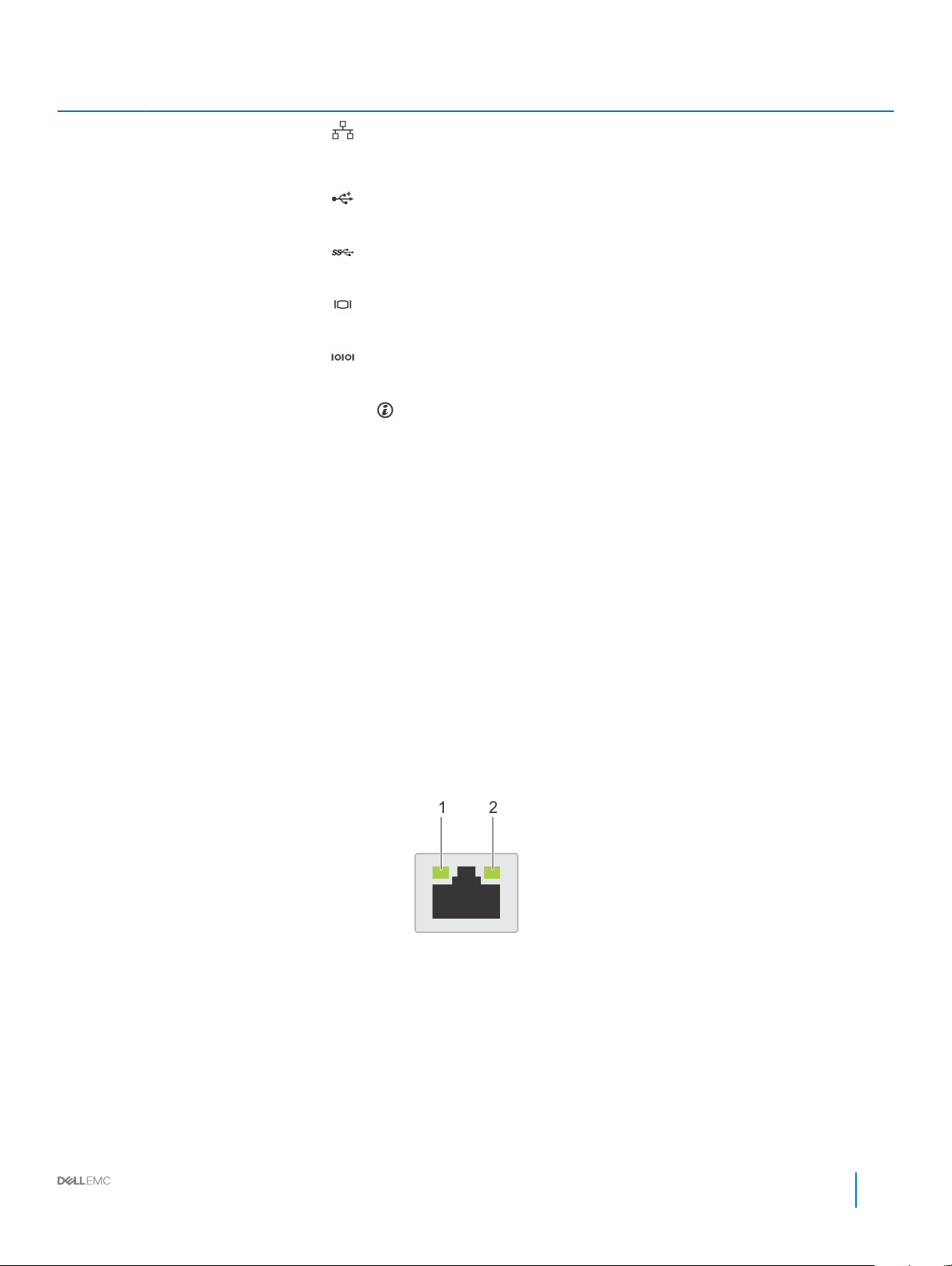
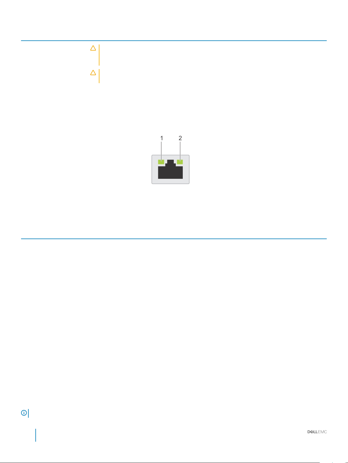
NIC indicator codes
Each NIC on the back of the system has indicators that provide information about the activity and link status. The activity LED indicator
indicates if data is owing through the NIC, and the link LED indicator indicates the speed of the connected network.
Figure 10. NIC indicator codes
link LED indicator 2 activity LED indicator
1
Dell EMC PowerEdge T440 Installation and Service Manual
Dell EMC PowerEdge T440 overview
19
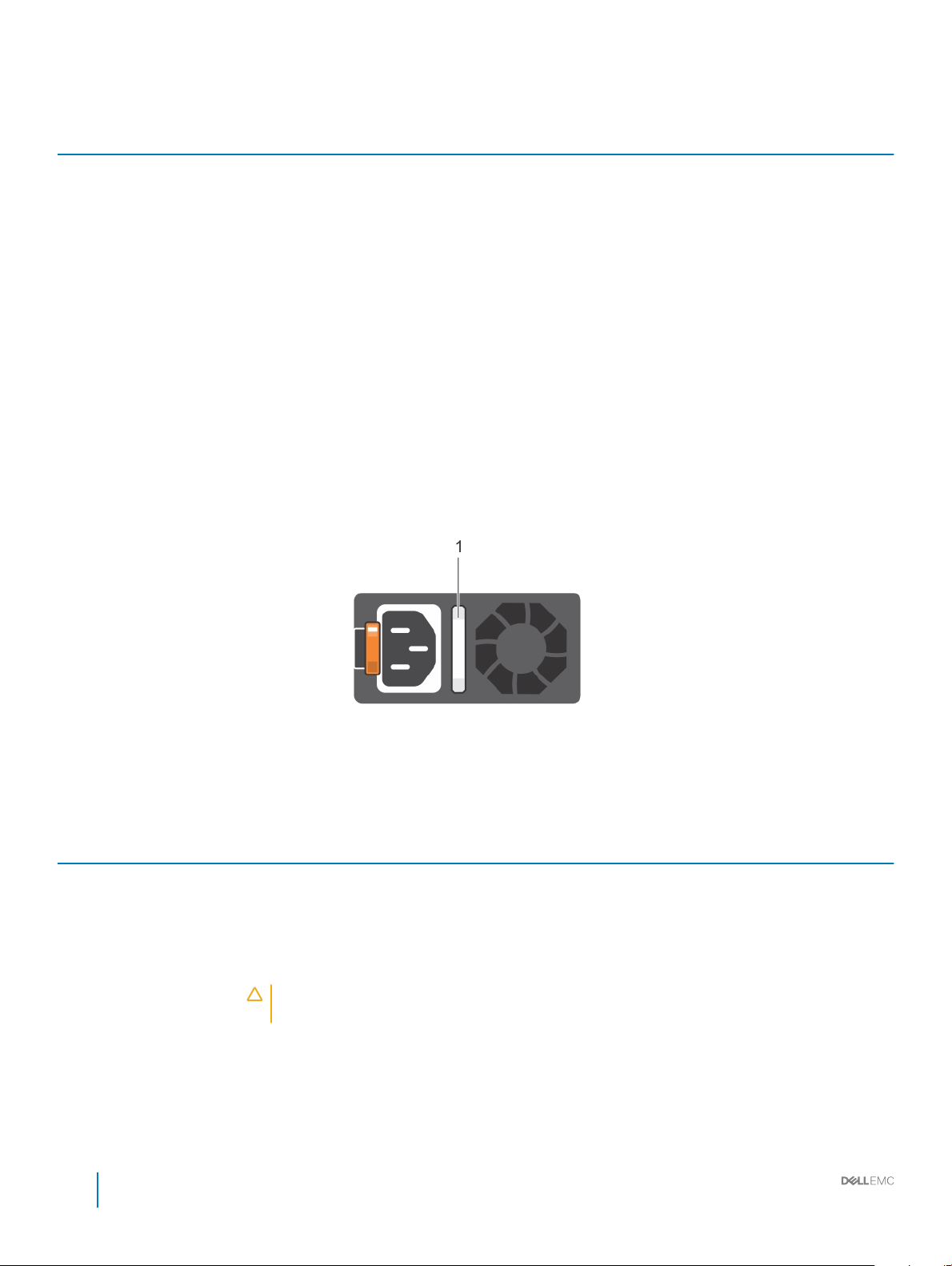
Table 6. NIC indicator codes
Status Condition
Link and activity indicators are o The NIC is not connected to the network.
Link indicator is green and activity indicator is blinking green The NIC is connected to a valid network at its maximum port speed and
data is being sent or received.
Link indicator is amber and activity indicator is blinking
green
Link indicator is green and activity indicator is o The NIC is connected to a valid network at its maximum port speed and
Link indicator is amber and activity indicator is o The NIC is connected to a valid network at less than its maximum port
Link indicator is blinking green and activity is o NIC identify is enabled through the NIC conguration utility.
The NIC is connected to a valid network at less than its maximum port
speed and data is being sent or received.
data is not being sent or received.
speed and data is not being sent or received.
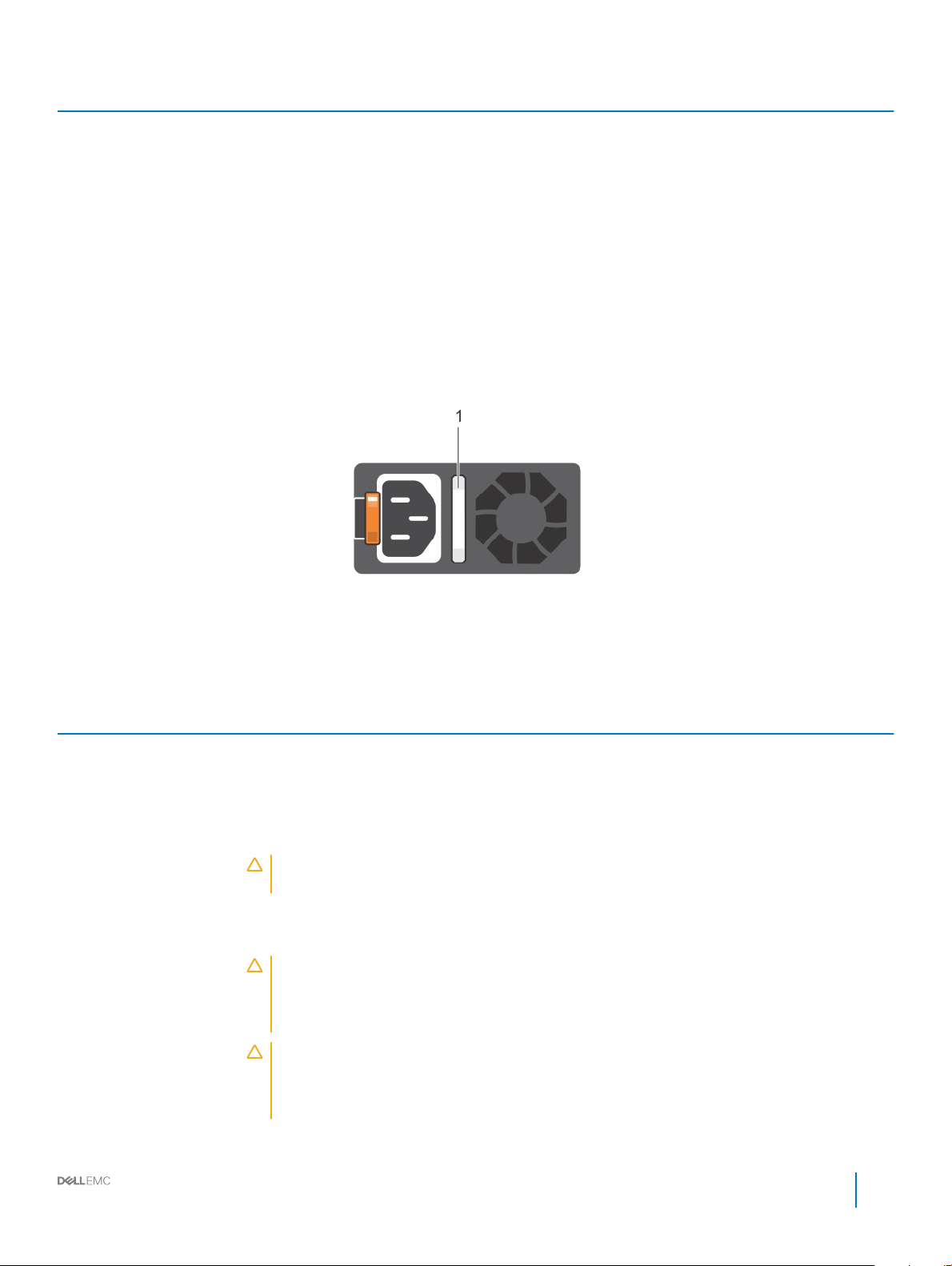
Power supply unit indicator codes
AC power supply units (PSUs) have an illuminated translucent handle that serves as an indicator. The indicator shows whether power is
present or if a power fault has occurred.
Figure 11. AC PSU status indicator
1
AC PSU status indicator/handle
Table 7. AC PSU status indicator codes
Power indicator codes Condition
Green A valid power source is connected to the PSU and the PSU is operational.
Blinking amber Indicates a problem with the PSU.
Not illuminated Power is not connected to the PSU.
Blinking green When the rmware of the PSU is being updated, the PSU handle blinks green.
CAUTION: Do not disconnect the power cord or unplug the PSU when updating rmware. If
rmware update is interrupted, the PSUs do not function.
Blinking green and turns o When hot-plugging a PSU, the PSU handle blinks green ve times at a rate of 4 Hz and turns o. This
indicates a PSU mismatch with respect to eciency, feature set, health status, or supported voltage.
20 Dell EMC PowerEdge T440 Installation and Service Manual
Dell EMC PowerEdge T440 overview

Power indicator codes Condition
CAUTION: If two PSUs are installed, both the PSUs must have the same type of label; for
example, Extended Power Performance (EPP) label. Mixing PSUs from previous generations of
PowerEdge servers is not supported, even if the PSUs have the same power rating. This results
in a PSU mismatch condition or failure to turn the system on.
CAUTION: When correcting a PSU mismatch, replace only the PSU with the blinking indicator.
Swapping the PSU to make a matched pair can result in an error condition and unexpected
system shutdown. To change from a high output conguration to a low output conguration or
vice versa, you must turn o the system.
CAUTION: AC PSUs support both 240 V and 120 V input voltages with the exception of Titanium
PSUs, which support only 240 V. When two identical PSUs receive dierent input voltages, they
can output dierent wattages, and trigger a mismatch.
CAUTION: If two PSUs are used, they must be of the same type and have the same maximum
output power.
Dell EMC PowerEdge T440 Installation and Service Manual
Dell EMC PowerEdge T440 overview
21
Diagnostic indicators
The diagnostic indicators on the system indicate operation and error status.
Diagnostics and indicators
The following pages contain the information about diagnostics and indicators for T440.
Status LED indicators
NOTE: The indicators display solid amber if any error occurs.
2
Figure 12. Status LED indicators
Table 8. Status LED indicators and descriptions
Icon Description Condition Corrective action
Health indicator The indicator turns solid blue if the
system is in good health.
The indicator blinks amber:
• When the system is turned on.
• When the system is in standby.
• If any error condition exists. For
example, a failed fan, PSU, or a
drive.
Drive indicator The indicator turns solid amber if
there is a drive error.
None required.
Check the System Event Log or system messages for the
specic issue. For more information about error
messages, see the Dell Event and Error Messages
Reference Guide at Dell.com/openmanagemanuals >
OpenManage software.
The POST process is interrupted without any video
output due to invalid memory congurations. See the
Getting help section.
• Check the System Event Log to determine if the drive
has an error.
• Run the appropriate Online Diagnostics test. Restart
the system and run embedded diagnostics (ePSA).
• If the drives are congured in a RAID array, restart the
system, and enter the host adapter conguration
utility program.
22 Dell EMC PowerEdge T440 Installation and Service Manual
Diagnostic indicators
Icon Description Condition Corrective action
Electrical indicator The indicator turns solid amber if the
system experiences an electrical error
(for example, voltage out of range, or
a failed power supply unit (PSU) or
voltage regulator).
Temperature
indicator
Memory indicator The indicator turns solid amber if a
PCIe indicator The indicator turns solid amber if a
The indicator turns solid amber if the
system experiences a thermal error
(for example, the ambient
temperature is out of range or there is
a fan failure).
memory error occurs.
PCIe card experiences an error.
Check the System Event Log or system messages for the
specic issue. If it is due to a problem with the PSU,
check the LED on the PSU. Reseat the PSU.
If the problem persists, see the Getting help section.
Ensure that none of the following conditions exist:
• A cooling fan has been removed or has failed.
• System cover, air shroud, memory module blank, or
back ller bracket is removed.
• Ambient temperature is too high.
• External airow is obstructed.
If the problem persists, see the Getting help section.
Check the System Event Log or system messages for the
location of the failed memory. Reseat the memory
module.
If the problem persists, see the Getting help section.
Restart the system. Update any required drivers for the
PCIe card. Reinstall the card.
If the problem persists, see the Getting help section.
NOTE: For more information about the
supported PCIe cards, see the Expansion card
installation guidelines section.
Related link
Getting help
Expansion card installation guidelines
System health and system ID indicator codes
The system health and system ID button is located on the front panel of your system.
Figure 13. System health and system ID buttons
Table 9. System health and system ID indicator codes
System health and system ID indicator code Condition
Solid blue Indicates that the system is turned on, system is healthy, and system
ID mode is not active. Press the system health and system ID button
to switch to system ID mode.
Blinking blue Indicates that the system ID mode is active. Press the system health
and system ID button to switch to system health mode.
Dell EMC PowerEdge T440 Installation and Service Manual
Diagnostic indicators
23
System health and system ID indicator code Condition
Solid amber Indicates that the system is in fail-safe mode. If the problem persists,
see the Getting help section.
Blinking amber Indicates that the system is experiencing a fault. Check the System
Event Log for specic error messages. For more information about
error messages, see the Dell Event and Error Messages Reference
Guide at Dell.com/openmanagemanuals > OpenManage software.
Related link
Getting help
Drive indicator codes
Each drive carrier has an activity LED indicator and a status LED indicator. The indicators provide information about the current status of
the drive. The activity LED indicator indicates whether the drive is currently in use or not. The status LED indicator indicates the power
condition of the drive.
Figure 14. Drive indicators
1
Drive activity LED indicator 2 Drive status LED indicator
3 Drive
NOTE: If the drive is in the Advanced Host Controller Interface (AHCI) mode, the status LED indicator does not turn on.
Table 10. Drive indicator codes
Drive status indicator code Condition
Flashes green twice per second Identifying drive or preparing for removal.
O Drive ready for removal.
NOTE: The drive status indicator remains o until all drives are
initialized after the system is turned on. Drives are not ready
for removal during this time.
24 Dell EMC PowerEdge T440 Installation and Service Manual
Diagnostic indicators
Drive status indicator code Condition
Flashes green, amber, and then turns o Predicted drive failure.
Flashes amber four times per second Drive failed.
Flashes green slowly Drive rebuilding.
Solid green Drive online.
Flashes green for three seconds, amber for three seconds, and
then turns o after six seconds
Rebuild stopped.
Power supply unit indicator codes
AC power supply units (PSUs) have an illuminated translucent handle that serves as an indicator. The indicator shows whether power is
present or if a power fault has occurred.
Figure 15. AC PSU status indicator
1
AC PSU status indicator/handle
Table 11. AC PSU status indicator codes
Power indicator codes Condition
Green A valid power source is connected to the PSU and the PSU is operational.
Blinking amber Indicates a problem with the PSU.
Not illuminated Power is not connected to the PSU.
Blinking green When the rmware of the PSU is being updated, the PSU handle blinks green.
CAUTION: Do not disconnect the power cord or unplug the PSU when updating rmware. If
rmware update is interrupted, the PSUs do not function.
Blinking green and turns o When hot-plugging a PSU, the PSU handle blinks green ve times at a rate of 4 Hz and turns o. This
indicates a PSU mismatch with respect to eciency, feature set, health status, or supported voltage.
CAUTION: If two PSUs are installed, both the PSUs must have the same type of label; for
example, Extended Power Performance (EPP) label. Mixing PSUs from previous generations of
PowerEdge servers is not supported, even if the PSUs have the same power rating. This results
in a PSU mismatch condition or failure to turn the system on.
CAUTION: When correcting a PSU mismatch, replace only the PSU with the blinking indicator.
Swapping the PSU to make a matched pair can result in an error condition and unexpected
system shutdown. To change from a high output conguration to a low output conguration or
vice versa, you must turn o the system.
Dell EMC PowerEdge T440 Installation and Service Manual
Diagnostic indicators
25
Power indicator codes Condition
CAUTION: AC PSUs support both 240 V and 120 V input voltages with the exception of Titanium
PSUs, which support only 240 V. When two identical PSUs receive dierent input voltages, they
can output dierent wattages, and trigger a mismatch.
CAUTION: If two PSUs are used, they must be of the same type and have the same maximum
output power.
NIC indicator codes
Each NIC on the back of the system has indicators that provide information about the activity and link status. The activity LED indicator
indicates if data is owing through the NIC, and the link LED indicator indicates the speed of the connected network.
Figure 16. NIC indicator codes
1
link LED indicator 2 activity LED indicator
Table 12. NIC indicator codes
Status Condition
Link and activity indicators are o The NIC is not connected to the network.
Link indicator is green and activity indicator is blinking green The NIC is connected to a valid network at its maximum port speed and
data is being sent or received.
Link indicator is amber and activity indicator is blinking
green
Link indicator is green and activity indicator is o The NIC is connected to a valid network at its maximum port speed and
Link indicator is amber and activity indicator is o The NIC is connected to a valid network at less than its maximum port
Link indicator is blinking green and activity is o NIC identify is enabled through the NIC conguration utility.
The NIC is connected to a valid network at less than its maximum port
speed and data is being sent or received.
data is not being sent or received.
speed and data is not being sent or received.
Enhanced Preboot System Assessment
If you experience a problem with your system, run the system diagnostics before contacting Dell for technical assistance. The purpose of
running system diagnostics is to test your system hardware without requiring more equipment or risking data loss. If you are unable to x
the problem yourself, service and support personnel can use the diagnostics results to help you solve the problem.
Dell Embedded system diagnostics
: The Dell Embedded System Diagnostics is also known as Enhanced Preboot System Assessment (ePSA) diagnostics.
NOTE
26 Dell EMC PowerEdge T440 Installation and Service Manual
Diagnostic indicators
The embedded system diagnostics provides a set of options for particular device groups or devices allowing you to:
• Run tests automatically or in an interactive mode.
• Repeat tests
• Display or save test results.
• Introduce more test options for extra information about the failed devices, run a thorough test.
• View status messages that inform you if tests are completed successfully.
• View error messages that inform you of problems encountered during testing.
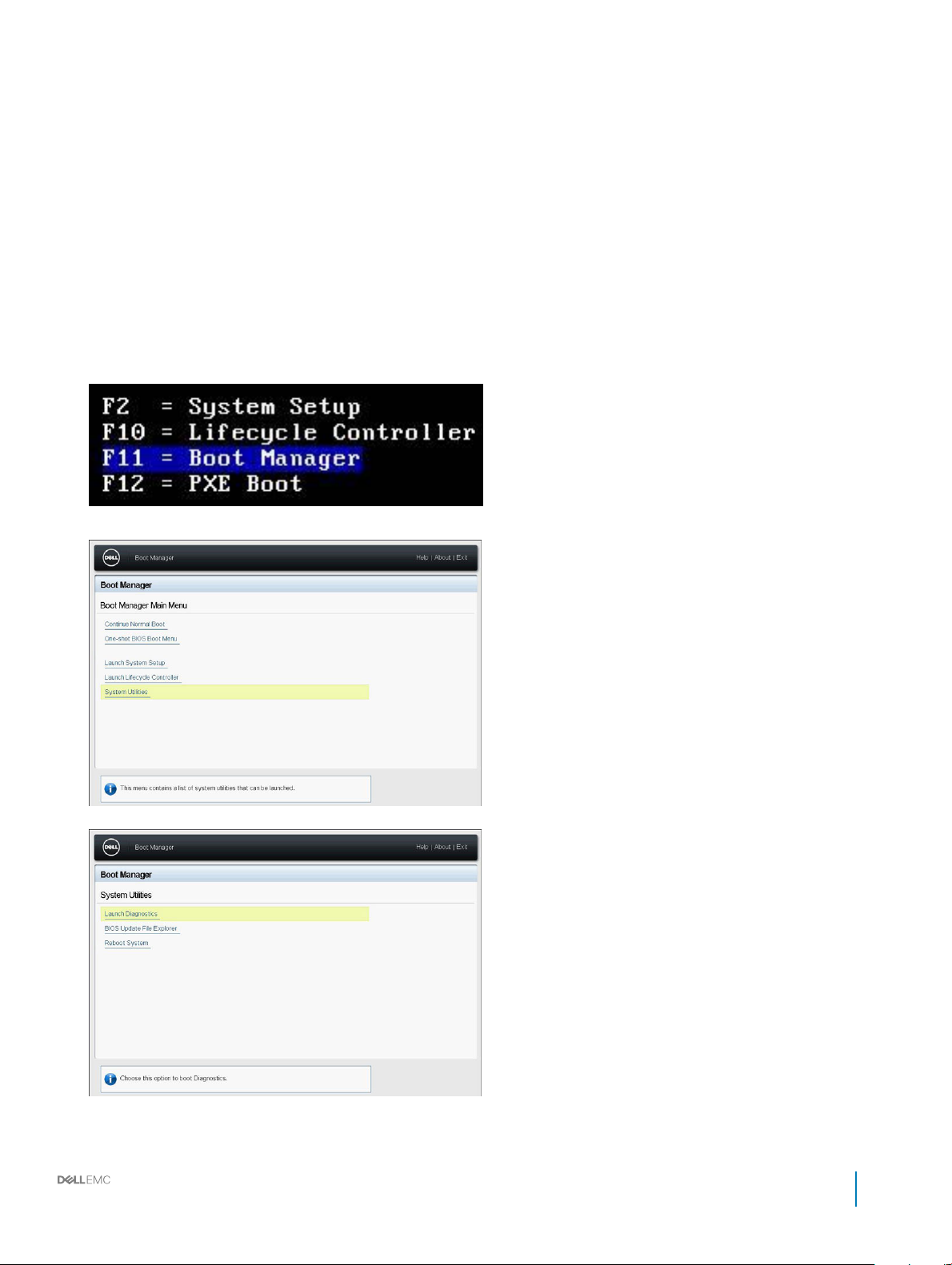
Running the Embedded system diagnostics from Boot Manager
To run the embedded system diagnostics from Boot Manager:
1 As the system boots, press <F11>.
2 Using the arrow keys select System Utilities → Launch Diagnostics.
3 Wait while the Quick Tests automatically run.
Dell EMC PowerEdge T440 Installation and Service Manual
Diagnostic indicators
27
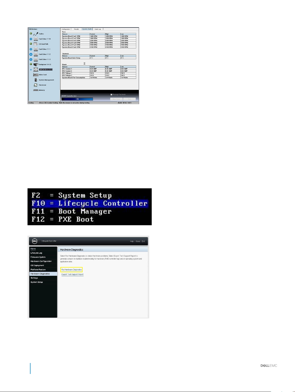
4 Once the tests have been completed, you can view the results and additional information on the Results tab, the System Health tab,
the Conguration tab, and the Event Log tab.
5 Close the Embedded System Diagnostics utility.
6 To leave the diagnostics, click Exit.
7 Click OK when prompted, and the system reboots.
Running the Embedded System Diagnostics from the Dell Lifecycle
Controller
To run the embedded system diagnostics from the Dell Lifecycle Controller:
1 As the system boots, press F10.
2 Select Hardware Diagnostics → Run Hardware Diagnostics.
Locating the Service Tag of your system
You can identify your system using the unique Express Service Code and Service Tag. Pull out the information tag in front of the system to
view the Express Service Code and Service Tag. Alternatively, the information may be on a sticker on the chassis of the system. The mini
28
Dell EMC PowerEdge T440 Installation and Service Manual
Diagnostic indicators

Enterprise Service Tag (EST) is found on the back of the system. This information is used by Dell to route support calls to the appropriate
personnel.
Dell EMC PowerEdge T440 Installation and Service Manual
Diagnostic indicators
29

Documentation resources
This section provides information about the documentation resources for your system.
Table 13. Additional documentation resources for your system
Task Document Location
Setting up your system
For more information about installing and securing
the system into a rack, see the rack documentation
included with your rack solution.
Dell.com/poweredgemanuals
3
For information about setting up and turning on the
system, see the Getting Started Guide document
that is shipped with your system.
Conguring your system For information about the iDRAC features,
conguring and logging in to iDRAC, and managing
your system remotely, see the Integrated Dell
Remote Access Controller User's Guide.
For information about installing the operating
system, see the operating system documentation.
For information about understanding Remote
Access Controller Admin (RACADM)
subcommands and supported RACADM interfaces,
see the RACADM Command Line Reference Guide
for iDRAC.
For information about updating drivers and
rmware, see the Methods to download rmware
and drivers section in this document.
Managing your system For information about systems management
software oered by Dell, see the Dell OpenManage
Systems Management Overview Guide.
For information about setting up, using, and
troubleshooting OpenManage, see the Dell
OpenManage Server Administrator User’s Guide.
Dell.com/poweredgemanuals
Dell.com/idracmanuals
Dell.com/operatingsystemmanuals
Dell.com/idracmanuals
To download drivers: Dell.com/support/drivers
Dell.com/openmanagemanuals
Dell.com/openmanagemanuals
For information about installing, using, and
troubleshooting Dell OpenManage Essentials, see
the Dell OpenManage Essentials User’s Guide.
For information about installing and using Dell
SupportAssist, see the Dell EMC SupportAssist
Enterprise User’s Guide.
For understanding the features of Dell Lifecycle
Controller, see the Dell Lifecycle Controller User’s
Guide.
30 Dell EMC PowerEdge T440 Installation and Service Manual
Documentation resources
Dell.com/openmanagemanuals
Dell.com/serviceabilitytools
Dell.com/idracmanuals
 Loading...