

Dell EMC PowerEdge MX7000 Installation And Service Manual

Dell EMC PowerEdge MX7000 Enclosure
Installation and Service Manual
Regulatory Model: E44S Series
Regulatory Type: E44S001

Notes, cautions, and warnings
NOTE: A NOTE indicates important information that helps you make better use of your product.
CAUTION: A CAUTION indicates either potential damage to hardware or loss of data and tells you how to avoid the problem.
WARNING: A WARNING indicates a potential for property damage, personal injury, or death.
© 2018 Dell Inc. or its subsidiaries. All rights reserved. Dell, EMC, and other trademarks are trademarks of Dell Inc. or its subsidiaries. Other trademarks
may be trademarks of their respective owners.
2018 - 09
Rev. A00

Contents
1 About this document......................................................................................................................................6
2 Next Generation Modular overview................................................................................................................7
PowerEdge MX architecture overview..........................................................................................................................10
3 Enclosure overview.......................................................................................................................................11
Front view of the enclosure.............................................................................................................................................12
Control panel...............................................................................................................................................................13
PSU indicators.............................................................................................................................................................16
Fan module indicator codes.......................................................................................................................................17
Back view of the enclosure............................................................................................................................................. 18
Management module indicator codes......................................................................................................................19
Locating the information tag of your system................................................................................................................ 19
4 Initial system setup and conguration...........................................................................................................21
Setting up your enclosure................................................................................................................................................21
Management module conguration................................................................................................................................21
Options to set up the management module IP address.........................................................................................21
Log in to the management module..........................................................................................................................22
Methods to download rmware and drivers.................................................................................................................22
Downloading drivers and rmware.................................................................................................................................23
LCD touch panel...............................................................................................................................................................23
Assigning an IP address out-of-the-box........................................................................................................................23
Conguring the Static IP address using the LCD...................................................................................................24
Conguring the DHCP IP address using the LCD..................................................................................................24
5 Installing and removing system components................................................................................................25
Safety instructions...........................................................................................................................................................25
Before working inside your enclosure............................................................................................................................25
After working inside your enclosure...............................................................................................................................25
Hot plug and Non-hot plug devices...............................................................................................................................26
Storage and compute sleds............................................................................................................................................ 26
Removing a sled blank...............................................................................................................................................26
Installing a sled blank..................................................................................................................................................27
Removing a compute or storage sled from the enclosure....................................................................................28
Installing a compute or storage sled into the enclosure........................................................................................30
Cooling fan modules........................................................................................................................................................ 32
Removing a front fan module................................................................................................................................... 32
Installing a front fan module......................................................................................................................................33
Removing a rear fan module.....................................................................................................................................34
Installing a rear fan module.......................................................................................................................................35
Power supply units ..........................................................................................................................................................36
Contents
3

Removing a power supply unit.................................................................................................................................36
Installing a power supply unit....................................................................................................................................37
Acoustic bae..................................................................................................................................................................38
Removing the air bae............................................................................................................................................. 38
Installing the air bae................................................................................................................................................39
Fabrics and modules........................................................................................................................................................40
Removing a blank from Fabric A or B slot.............................................................................................................. 40
Installing a blank in Fabric A or B slot.......................................................................................................................41
Removing a module from Fabric A or B slot...........................................................................................................42
Installing a module in Fabric A or B slot...................................................................................................................43
Removing a blank from Fabric C slot.......................................................................................................................44
Installing a blank in Fabric C slot.............................................................................................................................. 45
Removing a module from Fabric C slot...................................................................................................................46
Installing a module into Fabric C slot....................................................................................................................... 47
Removing a management module blank................................................................................................................. 48
Installing a management module blank....................................................................................................................49
Removing a management module........................................................................................................................... 50
Installing a management module..............................................................................................................................52
6 Technical specications...............................................................................................................................54
Component guidelines ....................................................................................................................................................54
Population rules..........................................................................................................................................................54
PSU redundancy and population rules....................................................................................................................55
Chassis dimensions..........................................................................................................................................................56
Chassis weight..................................................................................................................................................................57
Fan specications.............................................................................................................................................................57
PSU specications...........................................................................................................................................................57
Ports and connectors specications............................................................................................................................. 58
USB ports................................................................................................................................................................... 58
Mini DisplayPort......................................................................................................................................................... 58
PowerEdge MX modules ports and connectors.......................................................................................................... 58
PowerEdge MX740c................................................................................................................................................. 58
PowerEdge MX840c.................................................................................................................................................58
PowerEdge MX7116n................................................................................................................................................ 59
PowerEdge MX9116n................................................................................................................................................ 59
PowerEdge MX5108n................................................................................................................................................59
PowerEdge MXG610s...............................................................................................................................................60
PowerEdge MX 10GBASE-T Ethernet Pass-Through Module............................................................................. 60
PowerEdge MX 25 Gb Ethernet Pass-Through Module.......................................................................................60
Video specications.........................................................................................................................................................60
Environmental specications...........................................................................................................................................61
Standard operating temperature..............................................................................................................................62
Expanded operating temperature............................................................................................................................ 62
Particulate and gaseous contamination specications .........................................................................................63
7 Getting help.................................................................................................................................................65
4
Contents

Contacting Dell EMC.......................................................................................................................................................65
Documentation feedback................................................................................................................................................65
Accessing system information by using QRL............................................................................................................... 65
Quick Resource Locator for PowerEdge MX7000 enclosure...............................................................................66
Receiving automated support with SupportAssist .....................................................................................................66
8 Documentation resources............................................................................................................................ 67
Contents 5

About this document
This document provides an overview about the PowerEdge MX7000, information about installing and replacing components, technical
specications, and guidelines to follow while installing components.
1
6 About this document
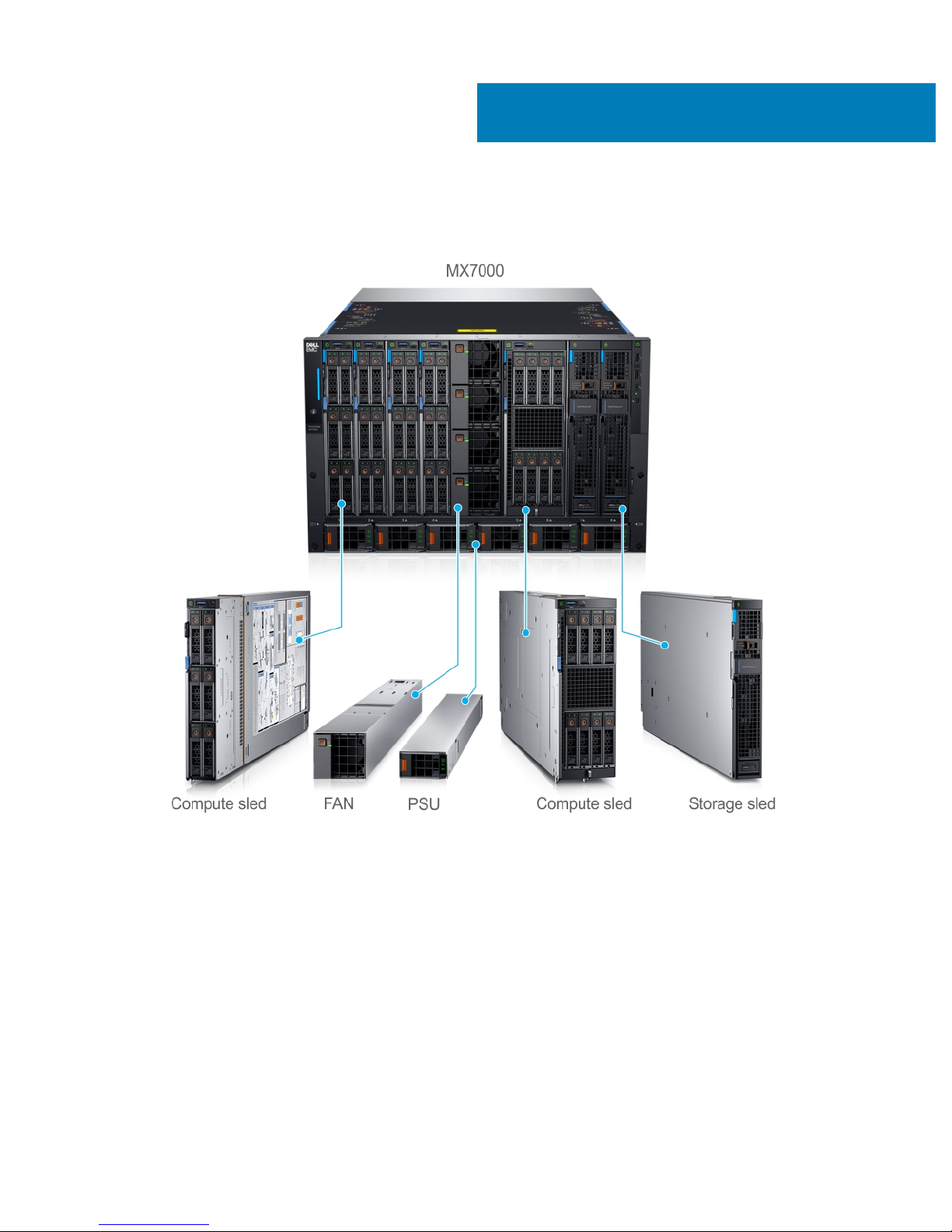
Next Generation Modular overview
Figure 1. Next Generation Modular - Front view
• Compute sleds - MX740c, and MX840c
• Storage sled - MX5016s
2
Next Generation Modular overview 7
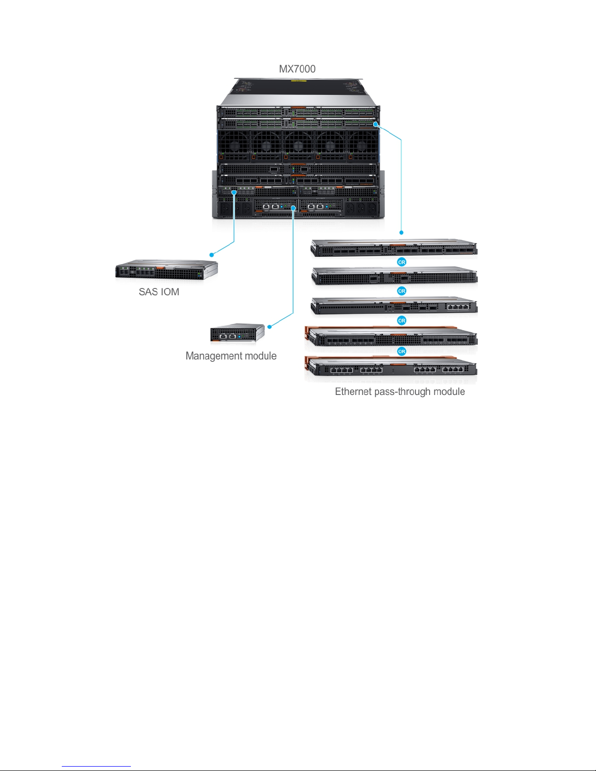
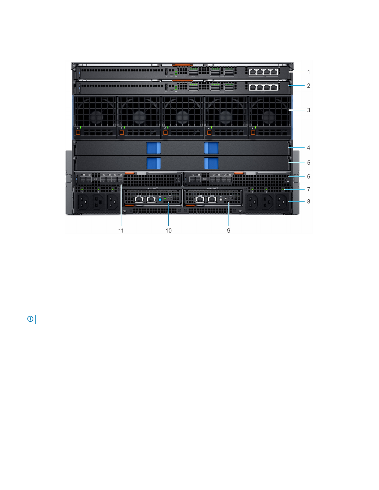
Figure 2. Next Generation Modular - Back view
The Dell EMC PowerEdge MX7000 enclosure supports the following sleds and I/O modules:
• I/O modules – Dell EMC Power Networking MX7116n
– Dell EMC Power Networking MX9116n Fabric Switching Engine
– Dell EMC Power Networking MX5108n Ethernet Switch
– Dell EMC Power Networking MXG610s Fibre Channel Switch
– Dell EMC PowerEdge MX5000s SAS Switch
• Ethernet Pass-Through Module – Dell EMC PowerEdge MX 10GBASE-T Ethernet Pass-Through Module
– Dell EMC PowerEdge MX 25 Gb Ethernet Pass-Through Module
• MX740c
The PowerEdge MX740c is a single-width compute sled that supports:
– Up to two Intel Xeon Scalable Processors
– Up to 24 DIMM slots
– Up to six 2.5-inch SAS, SATA, SSD, or NVMe drives
• MX840c
The PowerEdge MX840c is a double-width compute sled that supports:
– Up to four Intel Xeon Scalable Processors
8
Next Generation Modular overview

– Up to 48 DIMM slots
– Up to eight 2.5-inch SAS, SATA, SSD, or NVMe drives
• MX5016s
The PowerEdge MX5016s is a single-width storage sled that provides disk expansion for the PowerEdge MX series compute sleds that
support:
– Up to 16 hot-swappable 2.5-inch SAS drives
– Two hot-swappable expanders providing dual SAS paths for all drives
– Dual x4 SAS links to the MX platform infrastructure
– 12 Gb/s SAS
• Dell EMC Power Networking MX7116n Fabric Expander Module
The MX7116n Fabric Expander Module operates as an unmanaged Ethernet repeater to connect servers to the MX9116n Fabric
Switching Engine using QSFP28-DD connections. The Expander Module oers:
– Sixteen 25 GE server-facing ports
– Two QSFP28-DD ports for connection to a Fabric Switching Engine
• Dell EMC Power Networking MX9116n Fabric Switching Engine
The MX9116n Fabric Switching Engine is a scalable L2/L3 switch designed that provides high-bandwidth, low-latency 25 GbE
networking. This high-end switch oers:
– Sixteen 25 GE server-facing ports
– 12 QSFP28-DD ports that you can use to connect to Fabric Expanders or break out to: 8x10GE or 8x25GE ports for connection to
rack servers or other Ethernet devices, or 2x40GE/2x100GE ports for uplinks, connection to SAN storage, and switch
interconnects
– Two QSFP28 uplink ports that can operate in 1x100GE, 1x40GE, 4x25GE, 2x50GE, or 4x10GE mode
– Two QSFP28 unied ports that operate in Ethernet or Fibre Channel 1x100GE, 1x40GE, 4x25GE, 4x10GE, 2x50GE, or
8x8/16/32GFC mode
• Dell EMC Power Networking MX5108n Ethernet Switch
The MX5108n Ethernet Switch is a basic L2/L3 switch that is designed to provide high-performance, low-latency networking for the
PowerEdge MX7000 installations. It provides FCoE transit, but no native Fibre Channel functionality, and oers:
– Eight 25 GE server-facing ports
– Two 100 GE QSFP28 uplink ports
– One 40 GE QSFP28 uplink port
– Four 10GBASE-T uplink ports
• Dell EMC Power Networking MXG610s Fibre Channel Switch
The PowerEdge MXG610s Fibre Channel Switch provides the following hardware features:
– Up to 16 external FC ports to connect with external FC storage or an FC switch
– Up to 16 internal backplane FC ports to connect with the FC controller on the sleds
– A dual-core T1022E processor operating at 1.2 GHz delivers high performance, scalability, and advanced fabric vision functionality
– Two 32 Gbps short wavelength (SWL) optical SFP+ transceivers in the entry-level 8-port model
– Four 32 Gbps SWL optical SFP+ transceivers in the midlevel 16-port model
– Eight 32 Gbps SWL optical SFP+ transceivers in the enterprise 16-port model
• Dell EMC PowerEdge MX5000s SAS Switch
The PowerEdge MX5000s SAS IOM provides the following hardware features:
– Up to 8 internal 12Gbit/sec x4 SAS connections
– Internal SAS Fabric that enables the connectivity without any need for attached cables
• Dell EMC PowerEdge MX 10GBASE-T Ethernet Pass-Through Module
The Dell 10 Gb Ethernet pass-through module II supports 10 Gb connections. It provides a direct connection between the optional
internal Ethernet mezzanine card in the sled and an external Ethernet device. The Ethernet pass-through modules are hot-swappable.
The 10 Gb Ethernet pass-through module enables you to use optical SFP+ (short reach or long reach) and direct- attached copper
(DCA) SFP+ modules.
Next Generation Modular overview
9

NOTE: The Ethernet pass-through module does not support 1G mezzanine cards in the sleds.
• Dell EMC PowerEdge MX 25 Gb Ethernet Pass-Through Module
To better address high-performance network and scalability requirements, we are increasingly implementing 25 GbE for their
customers. These implementations capitalize on the 25GbE specication of the 25 Gigabit Ethernet Consortium. The specication uses
a single-lane 25 Gbps Ethernet links and is based on the existing IEEE 100 GbE standard. The 25 GbE is an easier upgrade path from 10
GbE as it ts into the existing model. It requires half the number of PCIe lanes that are compared to 40 GbE. It leads to better PCIe
bandwidth utilization, and lower power consumption. The 25GbE SFP28 physical interface specication also supports various form
factors, enabling exible conguration options.
Benets of deploying 25 GbE:
– Maximize performance and scalability
– Lower capital and operating expenses
– Future upgrade path
For more information about these modules and sleds, see Dell.com/poweredgemanuals.
PowerEdge MX architecture overview
The PowerEdge MX portfolio delivers a fully managed, high-performance system that frees up valuable IT resources and personnel so you
can focus on innovation. It enables you to work beyond silos and routine, daily, and time consuming operational management to realize your
IT and digital business transformations. With the kinetic architecture and Agile management, the MX portfolio dynamically congures
compute, storage, and fabric, increases team eectiveness and accelerates operations. The responsive design delivers the innovation and
longevity customers of all sizes need for their IT and digital business transformations.
The PowerEdge MX infrastructure provides:
Flexible architecture
• A exible architecture – Nondisruptive provisioning, on-demand allocation of compute, storage, and networking resource pools
• A scalable fabric – Cost-eective multichassis architecture with a broad array of open networking options and upgrade simplicity for
future I/O exibility
• Granular storage – Dense, highly exible, hot swappable, scale-out Direct Attached Storage sled with front access bays
Agile management
• End-to-end life cycle management and single point authentication for all devices from a single interface
• Simplied set-up/updates with no specialized training needed, and with multiple at-the-box management options
• An operational template methodology and comprehensive Rest API
Responsive design
• An industry-leading fabric, system thermal architecture, mechanical design, and control algorithms for dense congurations with future
compatibility
• A hardened design to protect, detect, and recover underlying infrastructure from cyber attacks
For more information about these modules and sleds, see their documents which are available at Dell.com/poweredgemanuals.
10
Next Generation Modular overview

Enclosure overview
The Dell EMC PowerEdge MX7000 is the next-generation M1000e follow-on chassis and a revolutionary architecture set to be the future
foundation of modular architecture.
The PowerEdge MX7000 enclosure is a 7U chassis that supports:
• Up to eight standard height, single-width sleds, or four standard height, double-width sleds.
Up to seven Storage sleds can be populated in the enclosure.
NOTE: One compute node must be present and it must be mapped to a storage node.
• Up to six hot swappable power supply units.
• Up to two hot swappable management modules.
• Up to six I/O modules:
– Four Fabric-A/B type IOMs
– Two Fabric-C type IOMs
• Four front accessible hot swappable cooling fans.
• Five rear accessible hot swappable cooling fans.
For more information about dual management modules, see Technical specications.
Topics:
• Front view of the enclosure
• Back view of the enclosure
• Locating the information tag of your system
3
Enclosure overview 11
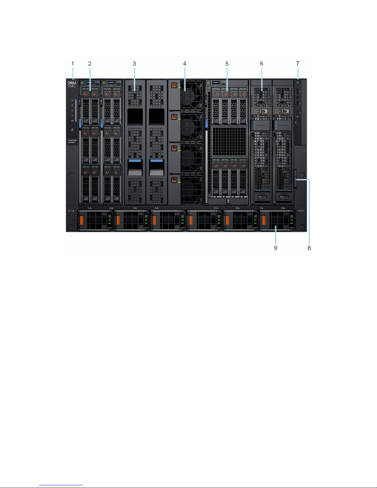
Front view of the enclosure
Figure 3. Front view of the enclosure
1
Left control panel 2 Single-width compute sled
3 Sled blank 4 Front fan (4)
5 Double-width compute sled 6 Single-width storage sled
7 Right control panel 8 Information tag
9 Power supply unit (6)
12 Enclosure overview
Control panel
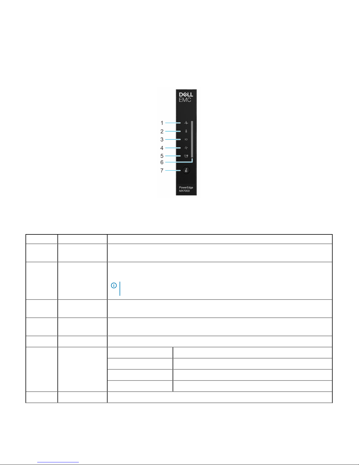
Left control panel
Figure 4. Left control panel - Status LED
Table 1.
Left control panel - LED indicator description
Indicator Description Status
1 System health Blinks amber for 2 seconds and is OFF for 1 second when the chassis health has degraded. By
default, the LED is unlit.
2 System temperature Blinks amber for 2 seconds and is OFF for 1 second when a thermal fault exists on the enclosure. By
default, the LED is unlit.
NOTE: A thermal fault includes excessive ambient temp, I/O modules thermal status,
PSU thermal status, and fan status.
3 I/O module health Blinks amber for 2 seconds and is OFF for 1 second when an I/O module is faulty. By default the
LED is unlit.
4 Fan health Blinks amber for 2 seconds and is OFF for 1 second when a front or rear mounted fan fails or has a
warning. By default, the LED is unlit.
5 Stack or group Indicates that the enclosure is a member of a group.
6 LED status bar Indicator status Description
Solid blue Indicates that the enclosure is healthy.
Blinking blue Indicates that the system ID mode is active.
Blinking amber Indicates that the system is experiencing a fault.
7 System ID button Allows you to identify the system or the installed sleds.
Enclosure overview 13
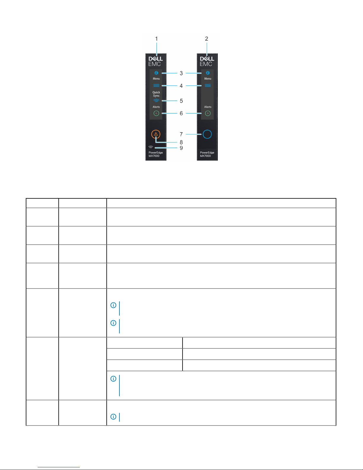
Figure 5. Left control panel - LCD options
Table 2. Left control panel - LCD panel description
Indicator Description Status
1 LCD with Quick
Sync
LCD enabled with Quick Sync module
2 LCD without Quick
Sync
LCD without Quick Sync module
3 System ID indicator
on LCD panel
This option is a button/indicator on the LCD panel to identify the chassis, or choose specic sleds to
identify.
4 Settings This option button provides access to the inventory and conguration data of the MX7000 enclosure.
It includes the Network Settings, System Information, (Model, Asset Tag, Service Tag), and
Language Settings.
5 Optional QuickSync
indicator (Only for
LCD with
QuickSync 2.0)
Enables access to QuickSync related controls and connection information.
NOTE: QuickSync feature allows you to manage your system using mobile devices. This
feature is only available on certain congurations.
NOTE: If not ordered at the time of purchase, the QuickSync module will not be available
on the enclosure.
6 System alerts
indicator
System ID Indicator status Description
Solid green The chassis has no degraded or critical alerts.
Solid amber The chassis has critical or degraded health alerts.
NOTE: This option button/indicator shows an amber colored alert icon and a combined
critical and degraded alert count. Pressing the button takes the user to the alert details
menu.
7
LCD activation
button/
Allows you to identify the enclosure.
NOTE: Press the button to activate the LCD.
14 Enclosure overview
Indicator Description Status
System ID
indicator/
Identication
indicator
System ID Indicator status Description
Blinking blue System ID is active.
Blinking amber Chassis alerts are present.
8 Error indicator The error indicator is displayed on the LCD when there are any critical/warning alerts on the
enclosure.
9 Optional Quick
Sync wireless
status indicator
Displays the connection status of the enclosure with any QuickSync enabled device.
NOTE: For more information about the feature, see LCD touch panel.
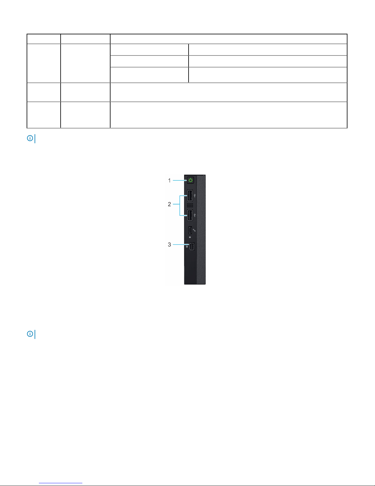
Right control panel
Figure 6. Right control panel
1
Power button 2 USB 2.0 port (2)
3 Mini DisplayPort
NOTE: For more information on the ports, see Technical specications.
Enclosure overview 15
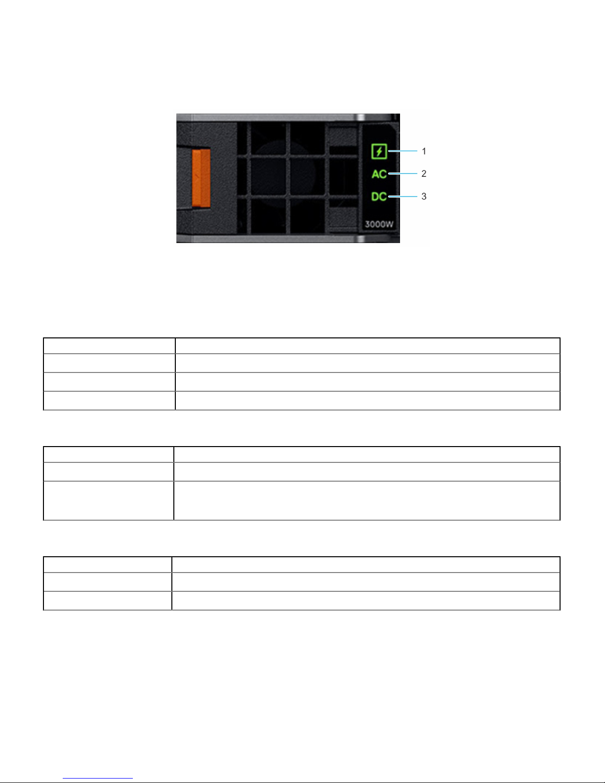
PSU indicators
Figure 7. PSU indicators
1 PSU health indicator 2 AC supply status indicator
3 DC output status indicator
Table 3. PSU health indicator codes
PSU health indicator Indicator state
PSU functioning normally Green
PSU faulty Blinking amber
PSU mismatch ON for 1 second, and then 5 blinks and OFF (non-repeating cycle).
Table 4. AC indicator codes
AC indicator Indicator state
AC source available ON
AC source unavailable or
power cable unplugged
OFF
Table 5. DC indicator codes
DC indicator Indicator state
DC output available ON
DC output unavailable OFF
16 Enclosure overview
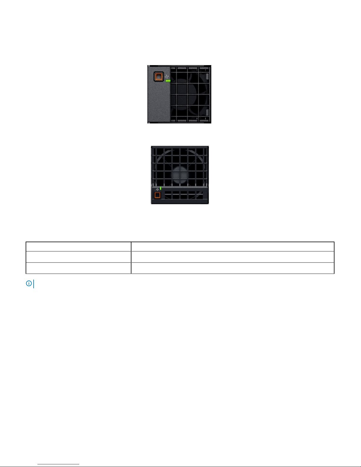
Fan module indicator codes
Figure 8. Front fan module
Figure 9. Rear fan module
Table 6. Fan module indicator codes
Fan indicators Indicator state
Fan functioning normally - Front/ Rear Solid green
Fan failure Blinks amber 2 seconds and 1 second OFF
NOTE: When the chassis is powered o with the AC connection that is powered on, only the rear fans are powered o.
Enclosure overview 17
Back view of the enclosure
Figure 10. Back view of the enclosure
1
Slot for Fabric A1 2 Slot for Fabric A2
3 Rear fans (5) 4 Slot for Fabric B1
5 Slot for Fabric B2 6 Slot for Fabric C2
7 Power cable connection status LED 8 C22 Power inlet connectors (6)
9 Management Module 2 10 Management Module 1
11 Slot for Fabric C1
NOTE: For more information about the ports and connectors, see Technical specications.
18 Enclosure overview
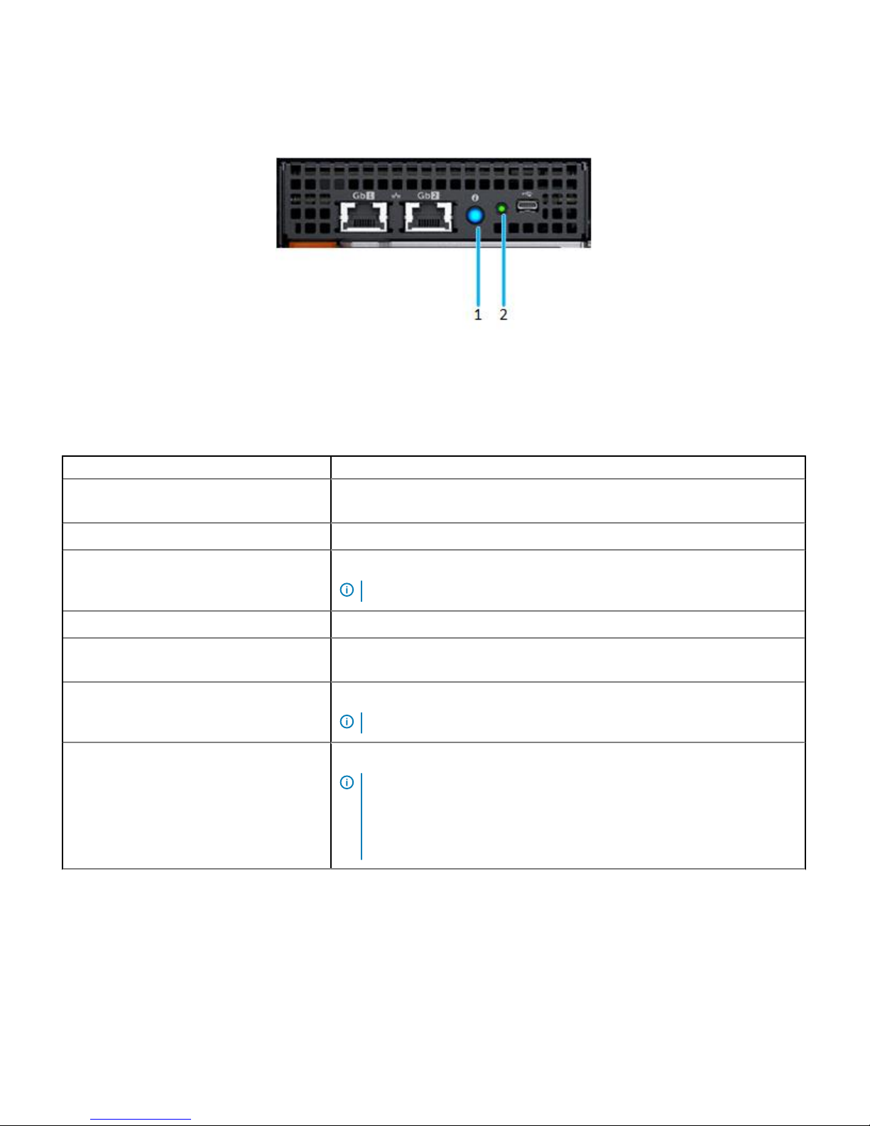
Management module indicator codes
Figure 11. Management module indicators
1 Status indicator, Identication button/ Indicator -
Dual color: Blue and amber
2 Power indicator - Green
Table 7. Management module indicator behavior
Status Indicator combination
Healthy chassis/ Management module
(Standby)
Power indicator ON (green), status indicator OFF
Healthy chassis/ Management module (Active) Power indicator ON (green), status indicator blue ON
Healthy chassis/ Management module
(Identifying mode)
Power indicator ON (green), status indicator blue blinking
NOTE: Available only when the management module is active.
Faulty chassis/ Management module (Active) Power indicator ON (green), status indicator amber blinking
Faulty chassis/ Management module
(Identifying mode)
Power indicator ON (green), status indicator blue blinking
Failed chassis/ Management module: Mode 1 Power indicator OFF, status indicator OFF
NOTE: Hardware failure prevents the management module from powering.
Failed chassis/ Management module: Mode 2 Power indicator OFF, status indicator Amber-solid
NOTE:
• The management module starts boot but is unable to boot to one or more
operating system partitions.
• The management module boots but detects a failure such as a network
switch failure, or a voltage regulator failure.
Locating the information tag of your system
You can identify your system using the unique express service code and Service Tag. Pull out the information tag in front of the system to
view the express service code and Service Tag. Alternatively, the information may be on a sticker on the back of the system chassis. The
mini Enterprise Service Tag (EST) is found on the back of the system chassis. Dell uses this information to route support calls to the
appropriate personnel.
Enclosure overview
19
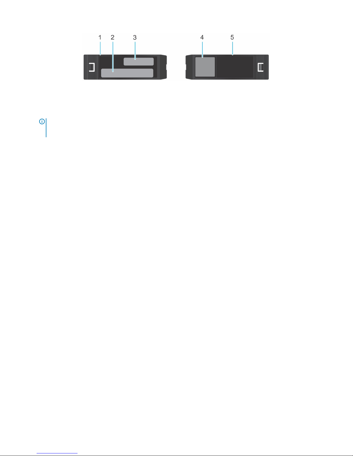
Figure 12. Locating the information tag of your system
1 Information tag (Top view)
2 MAC address and secure password label
NOTE: If you have opted for default access to the management module, the default password is available on the
Information tag. This label is blank, if you have not opted for secure default access, then the default username and
password are root and calvin.
3 Express Service Tag
4 Quick resource locator
5 Information tag (Bottom view)
20 Enclosure overview

Initial system setup and conguration
Setting up your enclosure
Complete the following steps to set up your enclosure:
1 Unpack the enclosure.
2 Install the enclosure into the rack. For more information, see the Rail Installation Guide at Dell.com/poweredgemanuals.
3 Connect the peripherals to the enclosure.
4 Connect the enclosure to its electrical outlet.
5 Power on the enclosure by pressing the power button.
NOTE: You can congure the static or DHCP IP address using the touch panel on the
chassis.
6 Power on the attached peripherals.
For more information about setting up your enclosure, see the Getting Started Guide that shipped with your enclosure.
Management module conguration
Using the management module (MM), you can manage SAS storage subsystem, drive assignments, and monitor the health status for the
associated SAS devices. You can manage SAS fabric by using the OpenManage Enterprise-Modular user interface to view inventory,
storage event logs and manage drive or enclosure assignments. For more information about managing the SAS fabric using OpenManage
Enterprise-Modular, see OpenManage Enterprise-Modular User's Guide available at Dell.com/openmanagemanuals > Chassis Management
Controllers.
Options to set up the management module IP address
Congure the initial network settings on your network infrastructure to enable the communication to and from the management module.
NOTE
: For static IP conguration, you must request for it at the time of purchase.
Use the OpenManage Essentials Quick Deploy feature to assign a static or DHCP IP address.
Interfaces
Document/Section
Dell Deployment
Toolkit
See Dell Deployment Toolkit User’s Guide at Dell.com/openmanagemanuals > OpenManage Deployment Toolkit
Dell Lifecycle
Controller
See Dell Lifecycle Controller User’s Guide at Dell.com/idracmanuals > Lifecycle Controller
OpenManage
Enterprise Modular
See Dell OpenManage Enterprise-Modular User’s Guide at Dell.com/openmanagemanuals > Chassis Management
Controllers
Server LCD panel See the LCD touch-panel section.
4
Initial system setup and conguration 21
 Loading...