

Page 1

Dell Latitude E5440
Owner's Manual
Regulatory Model: P44G
Regulatory Type: P44G001
Page 2

Notes, cautions, and warnings
NOTE: A NOTE indicates important information that helps you make better use of your computer.
CAUTION: A CAUTION indicates either potential damage to hardware or loss of data and tells you
how to avoid the problem.
WARNING: A WARNING indicates a potential for property damage, personal injury, or death.
Copyright © 2015 Dell Inc. All rights reserved. This product is protected by U.S. and international copyright and
intellectual property laws. Dell™ and the Dell logo are trademarks of Dell Inc. in the United States and/or other
jurisdictions. All other marks and names mentioned herein may be trademarks of their respective companies.
2015 -3
Rev. A04
Page 3

Contents
1 Working on Your Computer................................................................................5
Before Working Inside Your Computer................................................................................................ 5
Turning Off Your Computer..................................................................................................................6
After Working Inside Your Computer................................................................................................... 7
2 Removing and Installing Components............................................................. 8
Recommended Tools............................................................................................................................8
System Overview...................................................................................................................................9
Removing the Battery..........................................................................................................................10
Installing the Battery............................................................................................................................ 11
Removing the SD Card........................................................................................................................ 11
Installing the SD Card.......................................................................................................................... 11
Removing the ExpressCard................................................................................................................. 11
Installing the ExpressCard................................................................................................................... 12
Removing the SIM Card.......................................................................................................................12
Installing the SIM Card.........................................................................................................................12
Removing the Display Bezel................................................................................................................12
Installing the Display Bezel..................................................................................................................13
Removing the Display Panel................................................................................................................13
Installing the Display Panel................................................................................................................. 14
Removing the Camera........................................................................................................................ 14
Installing the Camera...........................................................................................................................15
Removing the Keyboard Trim............................................................................................................. 15
Installing the Keyboard Trim............................................................................................................... 15
Removing the Keyboard......................................................................................................................16
Installing the Keyboard........................................................................................................................ 17
Removing the Base Cover...................................................................................................................18
Installing the Base Cover.....................................................................................................................18
Removing the Optical Drive................................................................................................................18
Installing the Optical Drive..................................................................................................................19
Removing the Hard Drive................................................................................................................... 20
Installing the Hard Drive..................................................................................................................... 20
Removing the Memory Module.......................................................................................................... 21
Installing the Memory Module............................................................................................................ 21
Removing the WLAN Card..................................................................................................................22
Installing the WLAN Card....................................................................................................................22
Removing the Coin-Cell Battery........................................................................................................ 22
Installing the Coin-Cell Battery.......................................................................................................... 23
3
Page 4

Removing the Display Hinge.............................................................................................................. 23
Installing the Display Hinge................................................................................................................ 24
Removing the Palmrest.......................................................................................................................24
Installing the Palmrest.........................................................................................................................26
Removing the Display Assembly.........................................................................................................26
Installing the Display Assembly.......................................................................................................... 28
Removing the ExpressCard Cage.......................................................................................................28
Installing the ExpressCard Cage.........................................................................................................29
Removing the System Fan.................................................................................................................. 29
Installing the System Fan.................................................................................................................... 30
Removing the System Board...............................................................................................................31
Installing the System Board................................................................................................................ 33
Removing the Heatsink.......................................................................................................................34
Installing the Heatsink.........................................................................................................................34
Removing the I/O Board (Left)............................................................................................................35
Installing the I/O Board (Left)............................................................................................................. 36
Removing the I/O Board (Right)......................................................................................................... 36
Installing the I/O Board (Right)........................................................................................................... 37
Removing the Power Connector........................................................................................................37
Installing the Power Connector......................................................................................................... 38
Removing the Speakers...................................................................................................................... 38
Installing the Speakers........................................................................................................................ 39
Removing the Status-Light Board......................................................................................................40
Installing the Status-Light Board........................................................................................................40
3 System Setup.......................................................................................................42
Boot Sequence....................................................................................................................................42
Navigation Keys...................................................................................................................................42
System Setup Options.........................................................................................................................43
Updating the BIOS ..............................................................................................................................53
System and Setup Password...............................................................................................................53
Assigning a System Password and Setup Password.................................................................... 54
Deleting or Changing an Existing System and/or Setup Password.............................................54
4 Diagnostics.......................................................................................................... 56
Enhanced Pre-Boot System Assessment (ePSA) Diagnostics........................................................... 56
Device Status Lights............................................................................................................................ 57
Battery Status Lights............................................................................................................................57
5 Specifications...................................................................................................... 58
6 Contacting Dell...................................................................................................64
4
Page 5
1
Working on Your Computer
Before Working Inside Your Computer
Use the following safety guidelines to help protect your computer from potential damage and to help to
ensure your personal safety. Unless otherwise noted, each procedure included in this document assumes
that the following conditions exist:
• You have read the safety information that shipped with your computer.
• A component can be replaced or--if purchased separately--installed by performing the removal
procedure in reverse order.
WARNING: Before working inside your computer, read the safety information that shipped with
your computer. For additional safety best practices information, see the Regulatory Compliance
Homepage at www.dell.com/regulatory_compliance
CAUTION: Many repairs may only be done by a certified service technician. You should only
perform troubleshooting and simple repairs as authorized in your product documentation, or as
directed by the online or telephone service and support team. Damage due to servicing that is
not authorized by Dell is not covered by your warranty. Read and follow the safety instructions
that came with the product.
CAUTION: To avoid electrostatic discharge, ground yourself by using a wrist grounding strap or
by periodically touching an unpainted metal surface, such as a connector on the back of the
computer.
CAUTION: Handle components and cards with care. Do not touch the components or contacts
on a card. Hold a card by its edges or by its metal mounting bracket. Hold a component such as a
processor by its edges, not by its pins.
CAUTION: When you disconnect a cable, pull on its connector or on its pull-tab, not on the cable
itself. Some cables have connectors with locking tabs; if you are disconnecting this type of cable,
press in on the locking tabs before you disconnect the cable. As you pull connectors apart, keep
them evenly aligned to avoid bending any connector pins. Also, before you connect a cable,
ensure that both connectors are correctly oriented and aligned.
NOTE: The color of your computer and certain components may appear differently than shown in
this document.
To avoid damaging your computer, perform the following steps before you begin working inside the
computer.
1. Ensure that your work surface is flat and clean to prevent the computer cover from being scratched.
2. Turn off your computer (see Turning Off Your Computer).
3. If the computer is connected to a docking device (docked) such as the optional Media Base or
Battery Slice, undock it.
5
Page 6
CAUTION: To disconnect a network cable, first unplug the cable from your computer and
then unplug the cable from the network device.
4. Disconnect all network cables from the computer.
5. Disconnect your computer and all attached devices from their electrical outlets.
6. Close the display and turn the computer upside-down on a flat work surface.
NOTE: To avoid damaging the system board, you must remove the main battery before you
service the computer.
7. Remove the main battery.
8. Turn the computer top-side up.
9. Open the display.
10. Press the power button to ground the system board.
CAUTION: To guard against electrical shock, always unplug your computer from the
electrical outlet before opening the display.
CAUTION: Before touching anything inside your computer, ground yourself by touching an
unpainted metal surface, such as the metal at the back of the computer. While you work,
periodically touch an unpainted metal surface to dissipate static electricity, which could
harm internal components.
11. Remove any installed ExpressCards or Smart Cards from the appropriate slots.
Turning Off Your Computer
CAUTION: To avoid losing data, save and close all open files and exit all open programs before
you turn off your computer.
1. Shut down the operating system:
• In Windows 8:
– Using a touch-enabled device:
a. Swipe in from the right edge of the screen, opening the Charms menu and select
Settings.
b. Select the and then select Shut down
– Using a mouse:
a. Point to upper-right corner of the screen and click Settings.
b. Click the and select Shut down.
• In Windows 7:
1. Click Start .
2. Click Shut Down.
or
1. Click Start .
6
Page 7
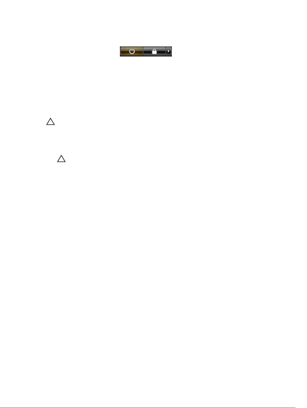
2. Click the arrow in the lower-right corner of the Start menu as shown below, and then click
Shut Down..
2. Ensure that the computer and all attached devices are turned off. If your computer and attached
devices did not automatically turn off when you shut down your operating system, press and hold
the power button for about 4 seconds to turn them off.
After Working Inside Your Computer
After you complete any replacement procedure, ensure you connect any external devices, cards, and
cables before turning on your computer.
CAUTION: To avoid damage to the computer, use only the battery designed for this particular
Dell computer. Do not use batteries designed for other Dell computers.
1. Connect any external devices, such as a port replicator, battery slice, or media base, and replace any
cards, such as an ExpressCard.
2. Connect any telephone or network cables to your computer.
CAUTION: To connect a network cable, first plug the cable into the network device and then
plug it into the computer.
3. Replace the battery.
4. Connect your computer and all attached devices to their electrical outlets.
5. Turn on your computer.
7
Page 8

Removing and Installing Components
This section provides detailed information on how to remove or install the components from your
computer.
Recommended Tools
The procedures in this document may require the following tools:
• Small flat-blade screwdriver
• #0 Phillips screwdriver
• #1 Phillips screwdriver
• Small plastic scribe
2
8
Page 9
System Overview
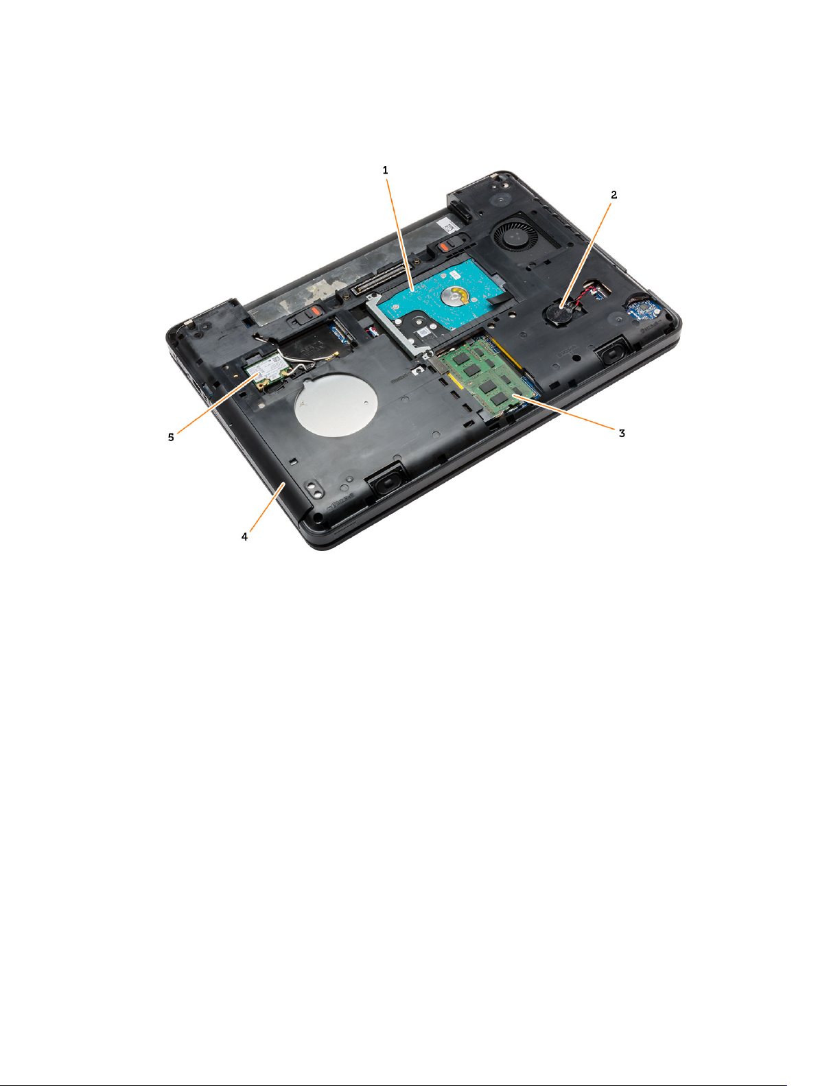
Figure 1. Inside View — Back
1. hard drive with isolation cap 2. coin-cell battery
3. memory module 4. optical drive
5. WLAN card
9
Page 10
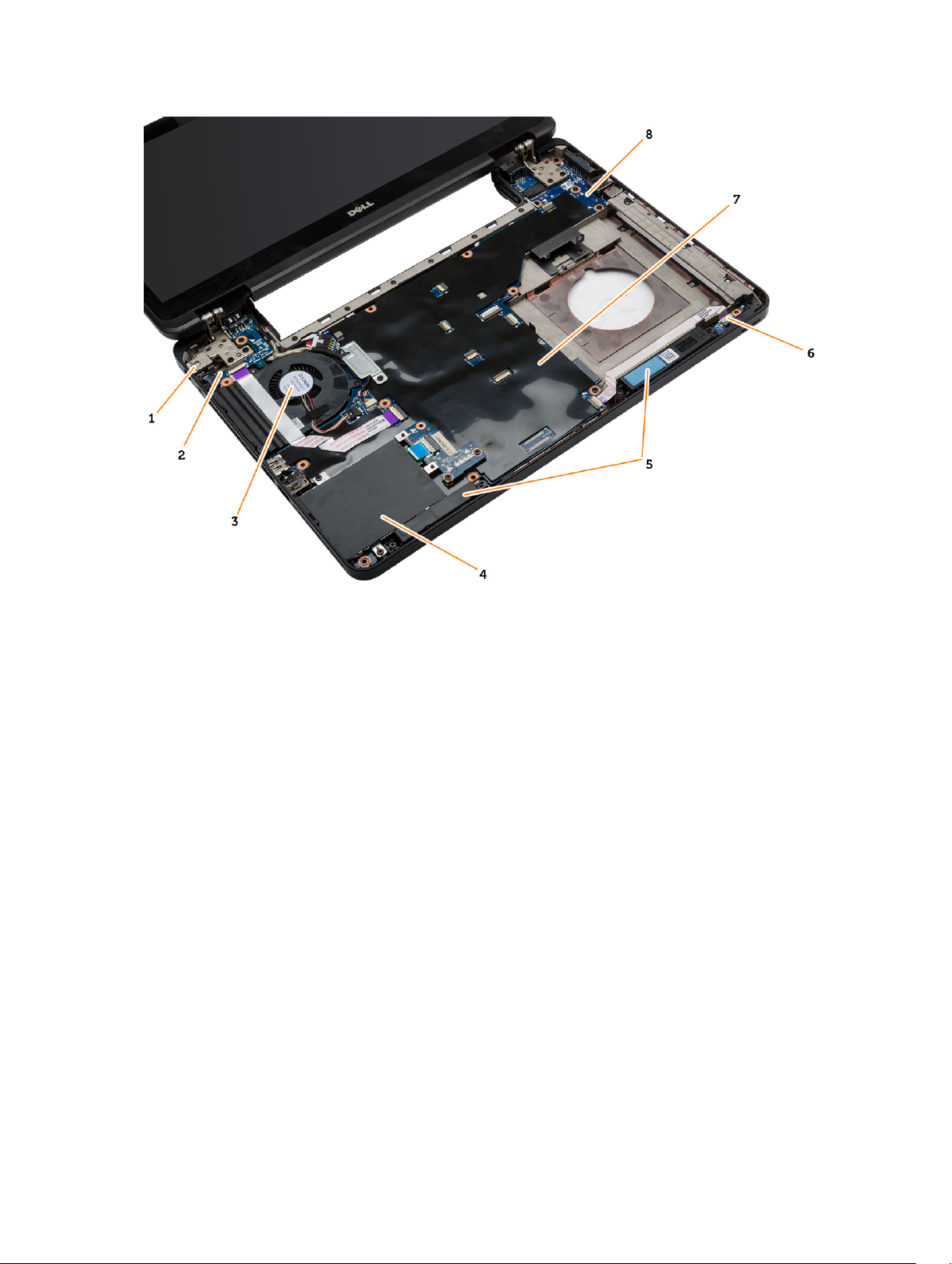
Figure 2. Inside view — Front
1. power connector 2. I/O board (left)
3. system fan 4. ExpressCard cage
5. speakers 6. status-light board
7. system board 8. I/O board (right)
Removing the Battery
1. Follow the procedures in Before Working Inside Your Computer.
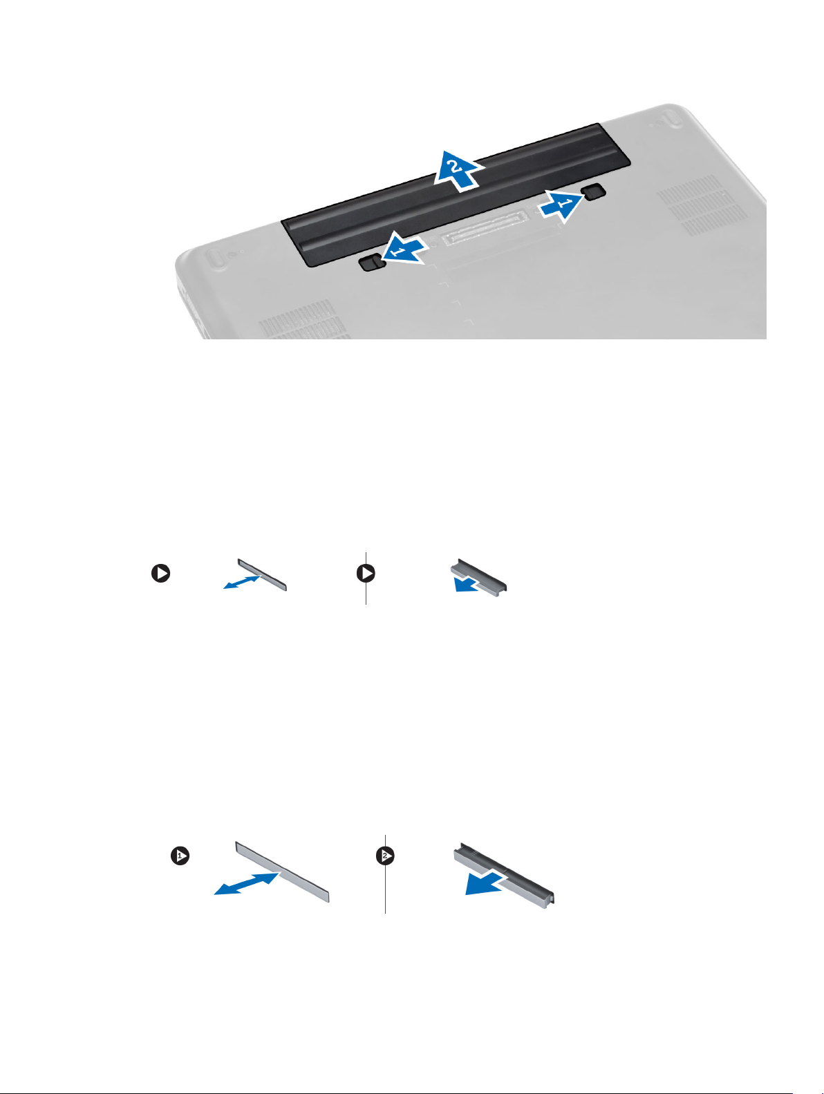
2. Perform the following steps:
a. Slide the battery release latches into the unlock position.
b. Push and remove the battery from the computer.
10
Page 11
Installing the Battery
1. Slide the battery into its slot until it clicks into place.
2. Follow the procedures in After Working Inside Your Computer.
Removing the SD Card
1. Follow the procedures in Before Working Inside Your Computer.
2. Press in on the SD card to release it from the computer.
3. Slide the SD card out of the computer.
Installing the SD Card
1. Push the SD card into its slot until it clicks into place.
2. Follow the procedures in After Working Inside Your Computer.
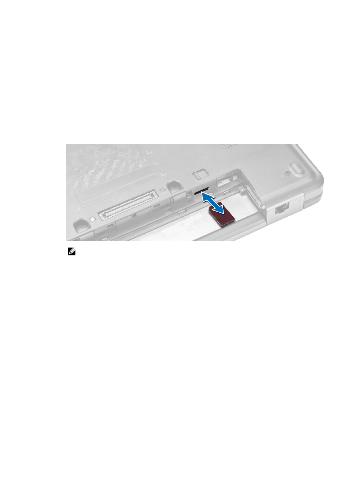
Removing the ExpressCard
1. Follow the procedures in Before Working On Your Computer.
2. Perform the following steps:
a. Push in on the ExpressCard to release from the computer [1].
b. Slide the ExpressCard out of the computer [2].
11
Page 12
Installing the ExpressCard
1. Slide the ExpressCard in its slot until it clicks in place.
2. Follow the procedures in After Working Inside Your Computer.
Removing the SIM Card
1. Follow the procedures in Before Working On Your Computer.
2. Remove the battery.
3. Press and release the SIM card located on the battery wall.
4. Slide the SIM card from the computer.
NOTE: The SIM slot in the computer supports only micro SIM.
Installing the SIM Card
1. Insert the SIM card into the slot.
2. Install the battery.
3. Follow the procedures in After Working Inside Your Computer.
Removing the Display Bezel
1. Follow the procedures in Before Working Inside Your Computer.
2. Remove the battery.
3. Perform the following steps:
a. Pry up the bottom edge of the display bezel.
b. Work your way around the sides and top edge of the display bezel.
12
Page 13
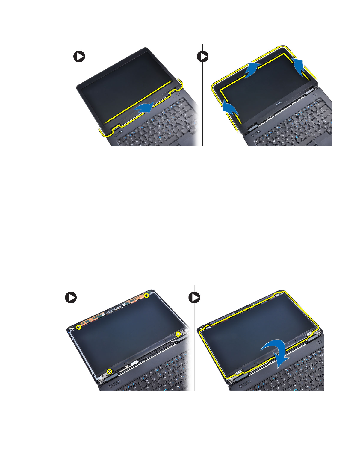
4. Remove the display bezel from the computer.
Installing the Display Bezel
1. Place the display bezel onto the display assembly.
2. Starting from the top corner, press on the display bezel and work around the entire bezel until it
snaps onto the display assembly.
3. Install the battery.
4. Follow the procedures in After Working Inside Your Computer.
Removing the Display Panel
1. Follow the procedures in Before Working Inside Your Computer.
2. Remove:
a. battery
b. display bezel
3. Remove the screws that secure the display panel and flip the panel over.
4. Perform the following steps:
13
Page 14
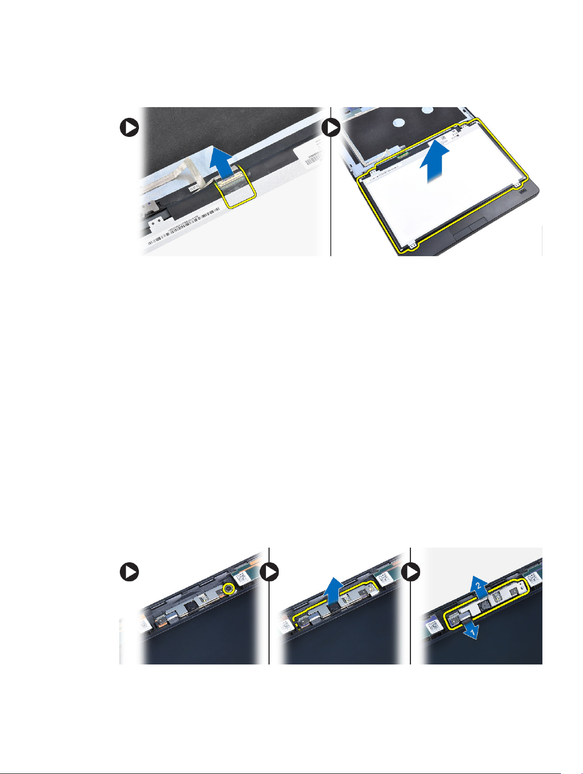
a. Lift the mylar tape and disconnect the low-voltage differential signaling (LVDS) cable from the
back of the display panel.
b. Remove the display panel from the display assembly.
Installing the Display Panel
1. Place the display panel to the display assembly.
2. Align the display panel in its original position.
3. Connect the low-voltage differential signaling (LVDS) cable to the display panel and attach the tape.
4. Flip the display panel over and tighten the screws to secure the display panel.
5. Install:
a. display bezel
b. battery
6. Follow the procedures in After Working Inside Your Computer.
Removing the Camera
1. Follow the procedures in Before Working Inside Your Computer.
2. Remove:
a. battery
b. display bezel
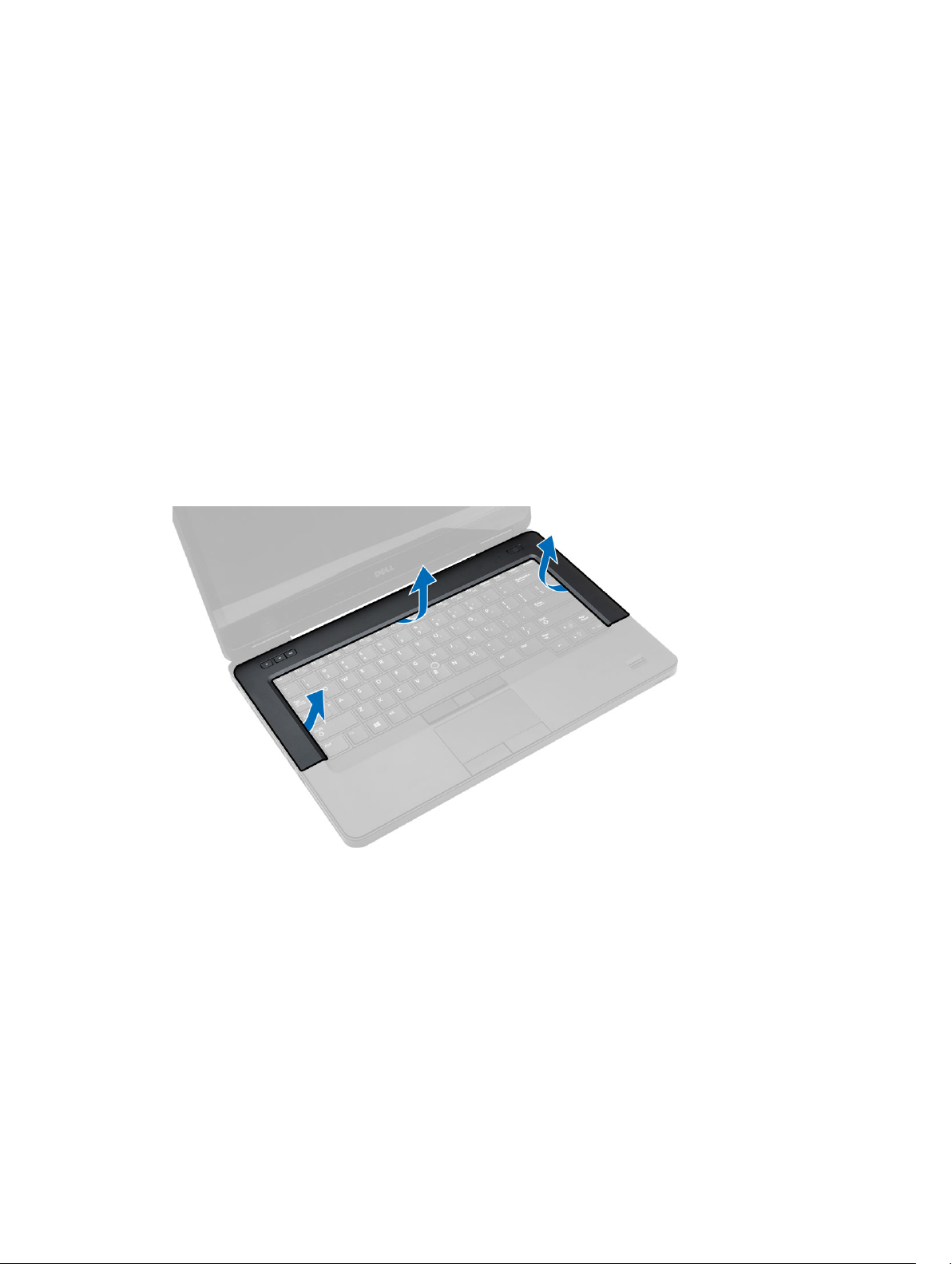
3. Perform the following steps:
a. Remove the screw that secures the camera and microphone module.
b. Disconnect the camera cable.
c. Lift and remove the camera and microphone module.
14
Page 15
Installing the Camera
1. Place the camera and microphone module on its place.
2. Connect the camera cable.
3. Tighten the screw to secure the camera and microphone module.
4. Install:
a. display bezel
b. battery
5. Follow the procedures in After Working Inside Your Computer.
Removing the Keyboard Trim
1. Follow the procedures in Before Working Inside Your Computer.
2. Remove the battery.
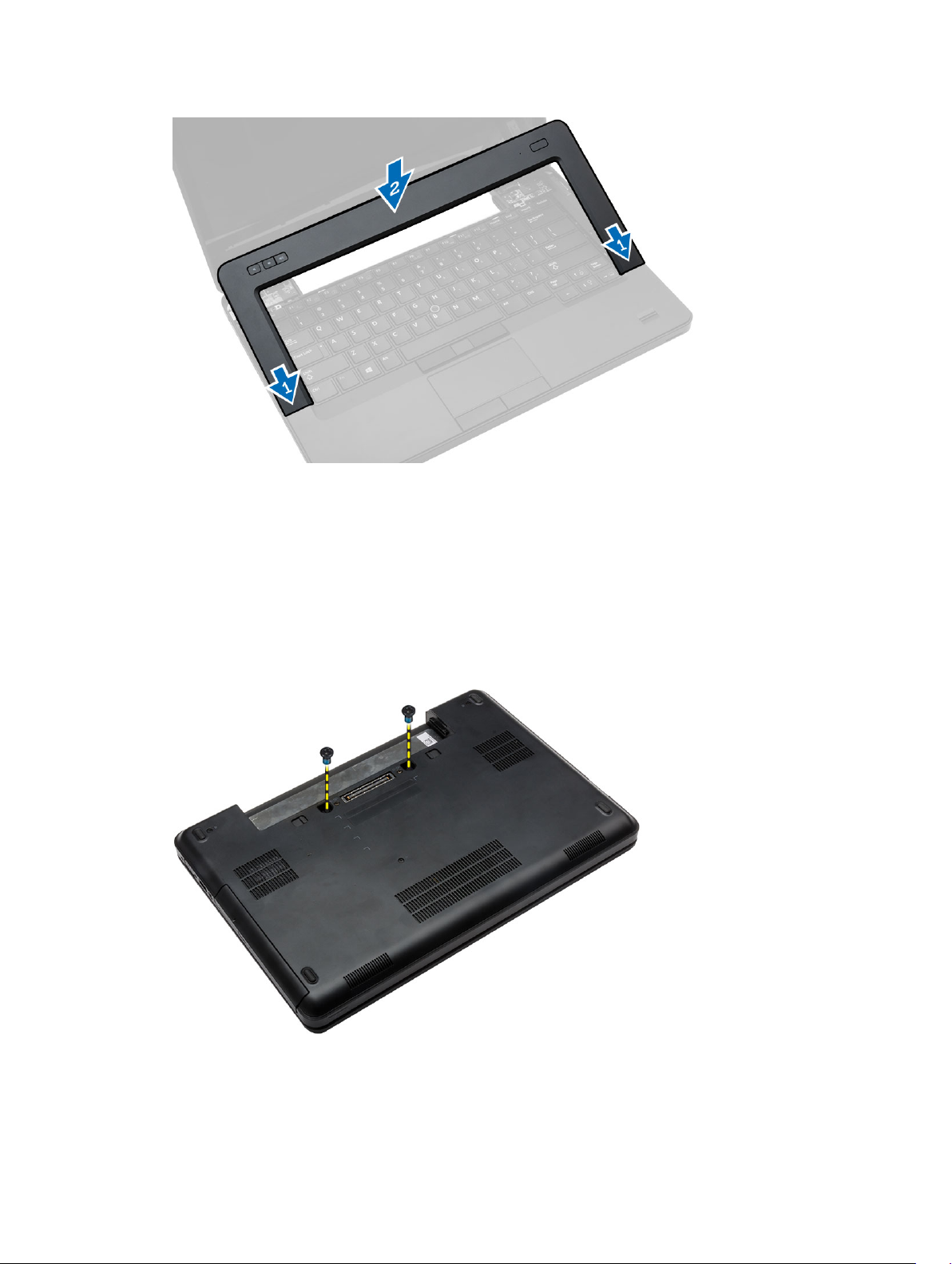
3. Perform the following steps:
a. Pry up the keyboard trim on its sides and the top edge.
b. Lift upwards and remove the keyboard trim from the computer.
Installing the Keyboard Trim
1. Align the keyboard trim to its place.
2. Press along the sides of the keyboard trim until it snaps in place.
15
Page 16
3. Install the battery.
4. Follow the procedures in After Working Inside Your Computer.
Removing the Keyboard
1. Follow the procedures in Before Working Inside Your Computer.
2. Remove:
a. battery
b. keyboard trim
3. Remove the screws at the back of the computer and flip the computer over.
4. Remove the screws that secure the keyboard [1] and lift the keyboard from the computer [2] and [3].
16
Page 17
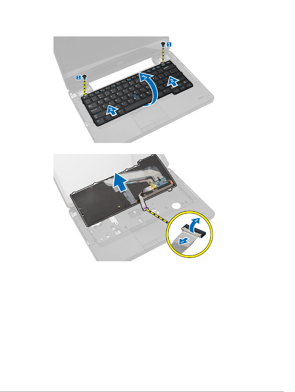
5. Disconnect the keyboard cable and remove the keyboard from the computer.
Installing the Keyboard
1. Connect the keyboard cable to the keyboard.
2. Place the keyboard into its place until all the metal tabs fit into their positions.
3. Press down on the keyboard to the left and right side ensuring that all the snaps are fully engaged
with the computer.
4. Install the screws to secure the keyboard to the palmrest.
5. Install the screws at the back of the computer.
6. Install:
a. keyboard trim
17
Page 18
b. battery
7. Follow the procedures in After Working Inside Your Computer.
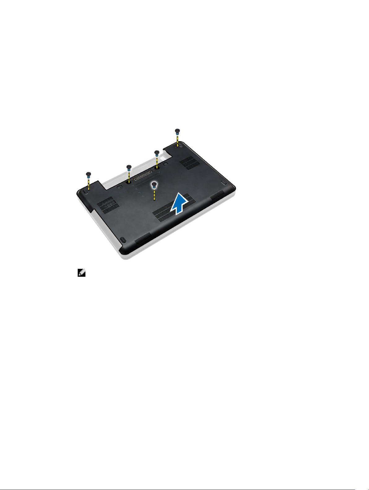
Removing the Base Cover
1. Follow the procedures in Before Working Inside Your Computer.
2. Remove the battery.
3. Perform the following steps:
a. Remove the screws that secure the base cover.
b. Pry the base cover towards the front of the computer and remove it from the computer.
NOTE: You may need a sharp tool to pry the base cover.
Installing the Base Cover
1. Insert the base cover into its slot until it clicks into place.
2. Tighten the screws to secure the base cover to the computer.
3. Install the battery.
4. Follow the procedures in After Working Inside Your Computer.
Removing the Optical Drive
1. Follow the procedures in Before Working Inside Your Computer.
2. Remove:
a. battery
b. base cover
3. Perform the following steps:
a. Remove the screw that secures the optical drive to the computer.
b. Push the optical drive away to remove it from the computer.
18
Page 19
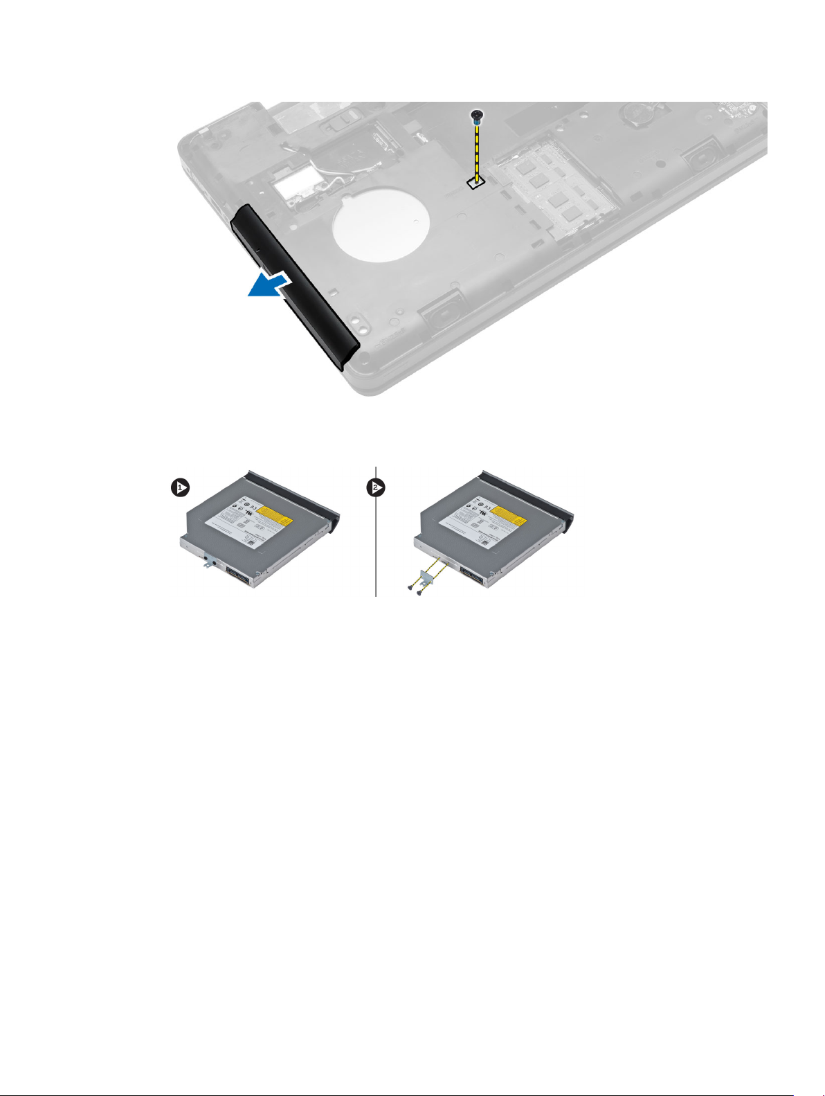
4. After removing the optical-drive bracket, perform the following steps:
a. Remove the screws that secure the optical-drive bracket [1].
b. Remove the optical-drive bracket from the optical drive [2].
5. Disengage the optical drive bezel tabs to separate the optical drive bezel from the optical drive.
6. Remove the optical-drive bezel.
Installing the Optical Drive
1. Engage the optical-drive bezel tabs to attach the optical-drive bezel to the optical drive.
2. Install the optical-drive bracket.
3. Tighten the screws to secure the optical-drive bracket.
4. Insert the optical drive into the computer.
5. Tighten the screw to secure the optical drive in its place.
6. Install:
a. base cover
b. battery
7. Follow the procedures in After Working Inside Your Computer.
19
Page 20
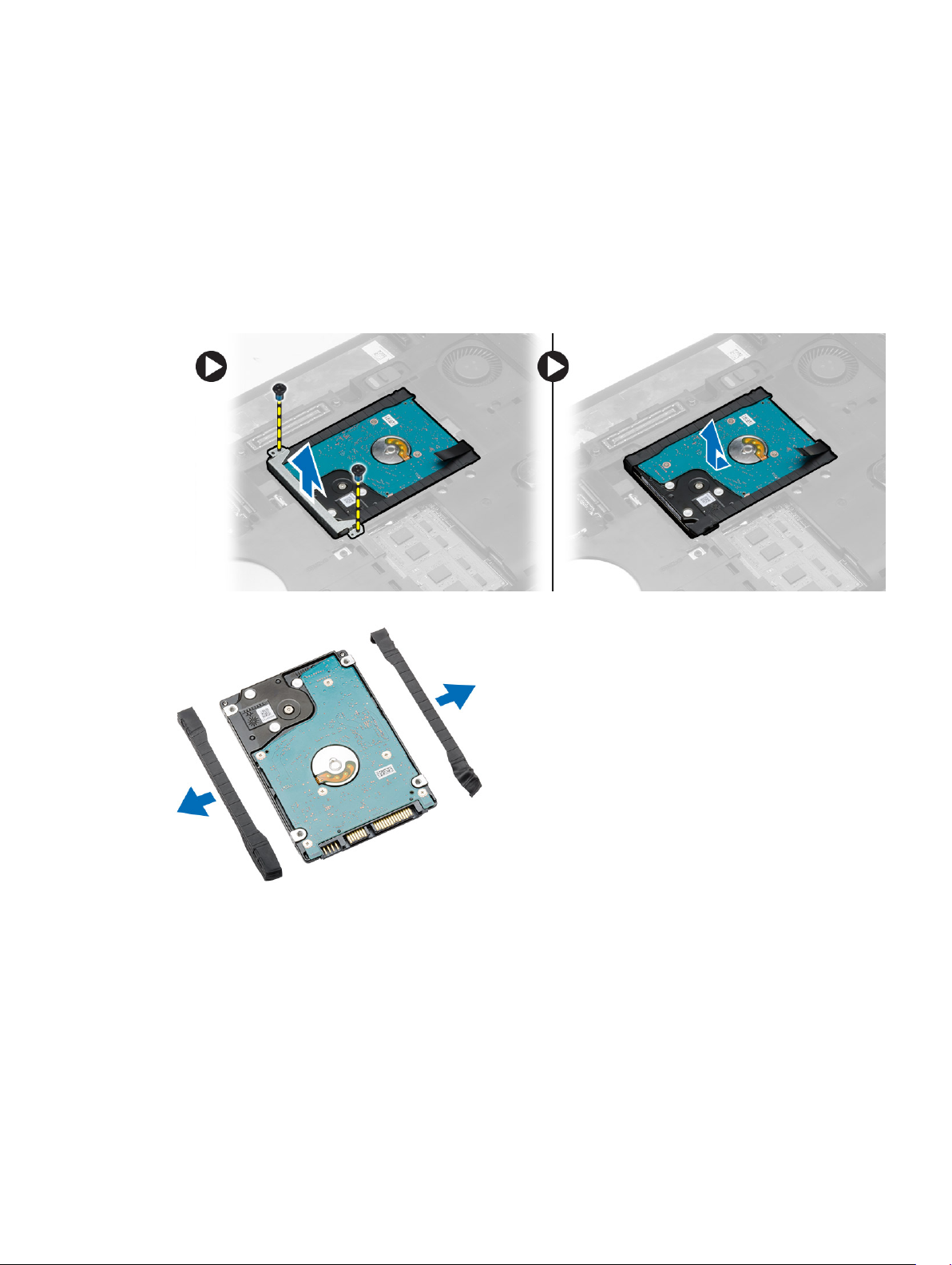
Removing the Hard Drive
1. Follow the procedures in Before Working Inside Your Computer.
2. Remove:
a. battery
b. base cover
3. Perform the following steps:
a. Remove the screws that secure the hard-drive bracket in place.
b. Slide and pull the hard drive to remove from its connectors.
4. Remove the hard-drive isolation cap from the hard drive.
Installing the Hard Drive
1. Engage the hard-drive isolation cap to the hard drive.
20
Page 21
2. Place the hard drive on its connector.
3. Place the hard-drive bracket on the hard drive and tighten the screws to secure the hard-drive
bracket in place.
4. Install:
a. base cover
b. battery
5. Follow the procedures in After Working Inside Your Computer.
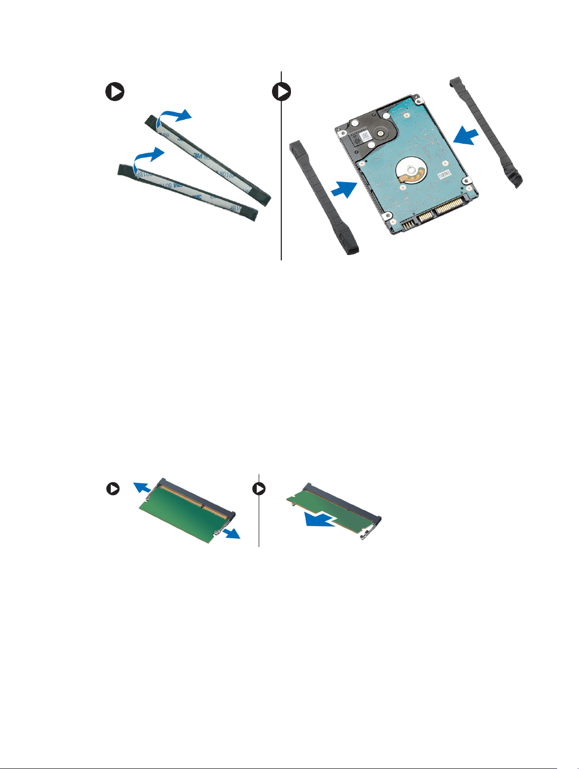
Removing the Memory Module
1. Follow the procedures in Before Working Inside Your Computer.
2. Remove:
a. battery
b. base cover
3. Pry the retention clips away from the memory module until it pops up.
4. Lift up the memory module and remove it from the computer.
Installing the Memory Module
1. Insert the memory into the memory socket.
2. Press the clips to secure the memory module to the system board.
3. Install:
a. base cover
b. battery
21
Page 22
4. Follow the procedures in After Working Inside Your Computer.
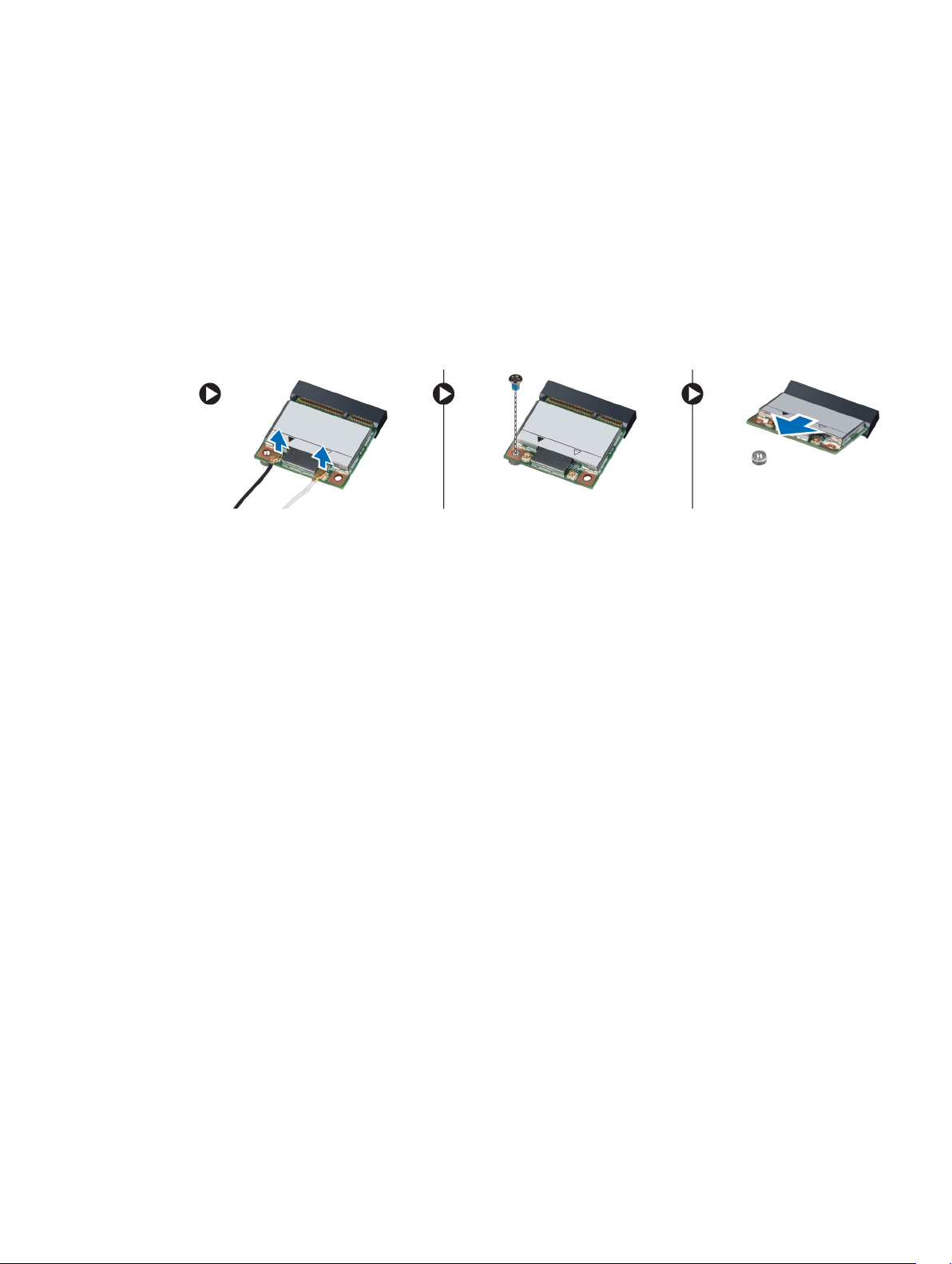
Removing the WLAN Card
1. Follow the procedures in Before Working Inside Your Computer.
2. Remove:
a. battery
b. base cover
3. Perform the following steps:
a. Disconnect the antennae cables from the WLAN card.
b. Remove the screw that secures the WLAN card to the computer.
c. Remove the WLAN card from its slot on the system board.
Installing the WLAN Card
1. Insert the WLAN card into its connector on the system board.
2. Connect the antenna cables to the respective connectors marked on the WLAN card.
3. Tighten the screw to secure the WLAN card to the computer.
4. Install:
a. base cover
b. battery
5. Follow the procedures in After Working Inside Your Computer.
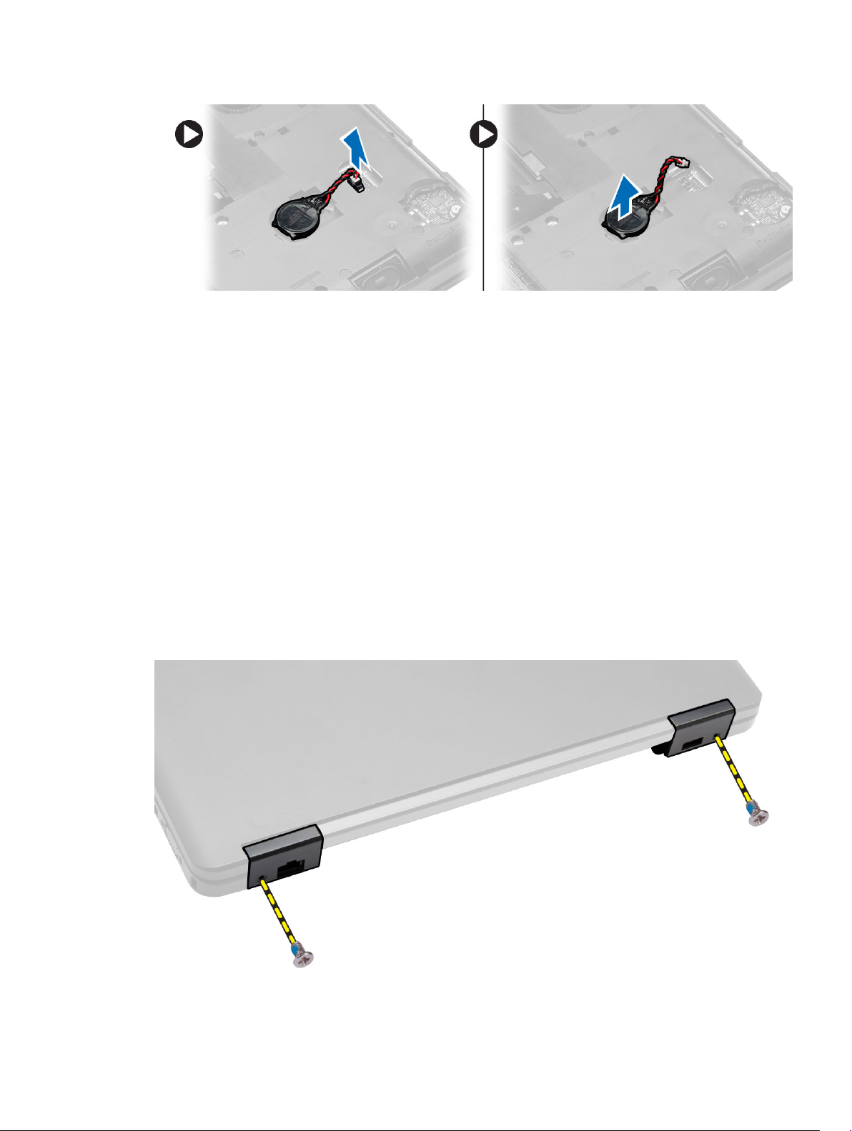
Removing the Coin-Cell Battery
1. Follow the procedures in Before Working Inside Your Computer.
2. Remove:
a. battery
b. base cover
3. Perform the following steps:
a. Disconnect the coin-cell battery cable from the system board.
b. Pry and remove the coin-cell battery from the adhesive.
22
Page 23
Installing the Coin-Cell Battery
1. Place the coin-cell battery on the system board with adhesive side downwards.
2. Connect the coin-cell battery cable to the system board.
3. Install:
a. base cover
b. battery
4. Follow the procedures in After Working Inside Your Computer.
Removing the Display Hinge
1. Follow the procedures in Before Working Inside Your Computer.
2. Remove:
a. battery
b. base cover
c. keyboard trim
d. keyboard
3. Remove the screws that secure the display hinge at the back of the computer.
23
Page 24
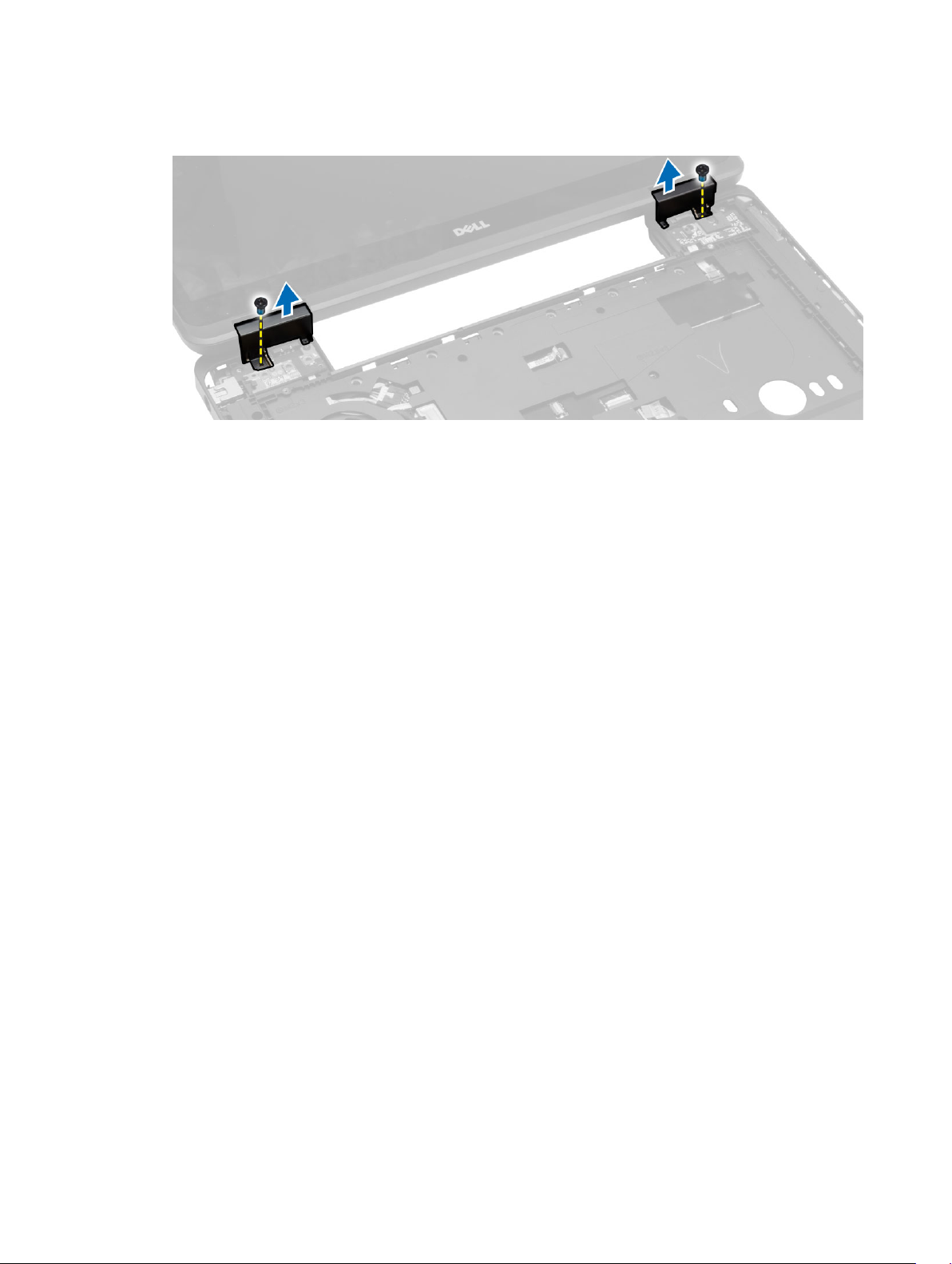
4. Remove the screws that secure the display hinge at the front of the computer. Press and remove the
display hinge from the computer.
Installing the Display Hinge
1. Place the display hinge on the computer.
2. Tighten the screws to secure the display hinge at the front and back of the computer.
3. Install:
a. keyboard
b. keyboard trim
c. base cover
d. battery
4. Follow the procedures in After Working Inside Your Computer.
Removing the Palmrest
1. Follow the procedures in Before Working Inside Your Computer.
2. Remove:
a. SD card
b. battery
c. base cover
d. keyboard trim
e. keyboard
f. memory
g. optical drive
h. hard drive
i. display hinge
3. Remove the screws at the bottom of the computer.
24
Page 25
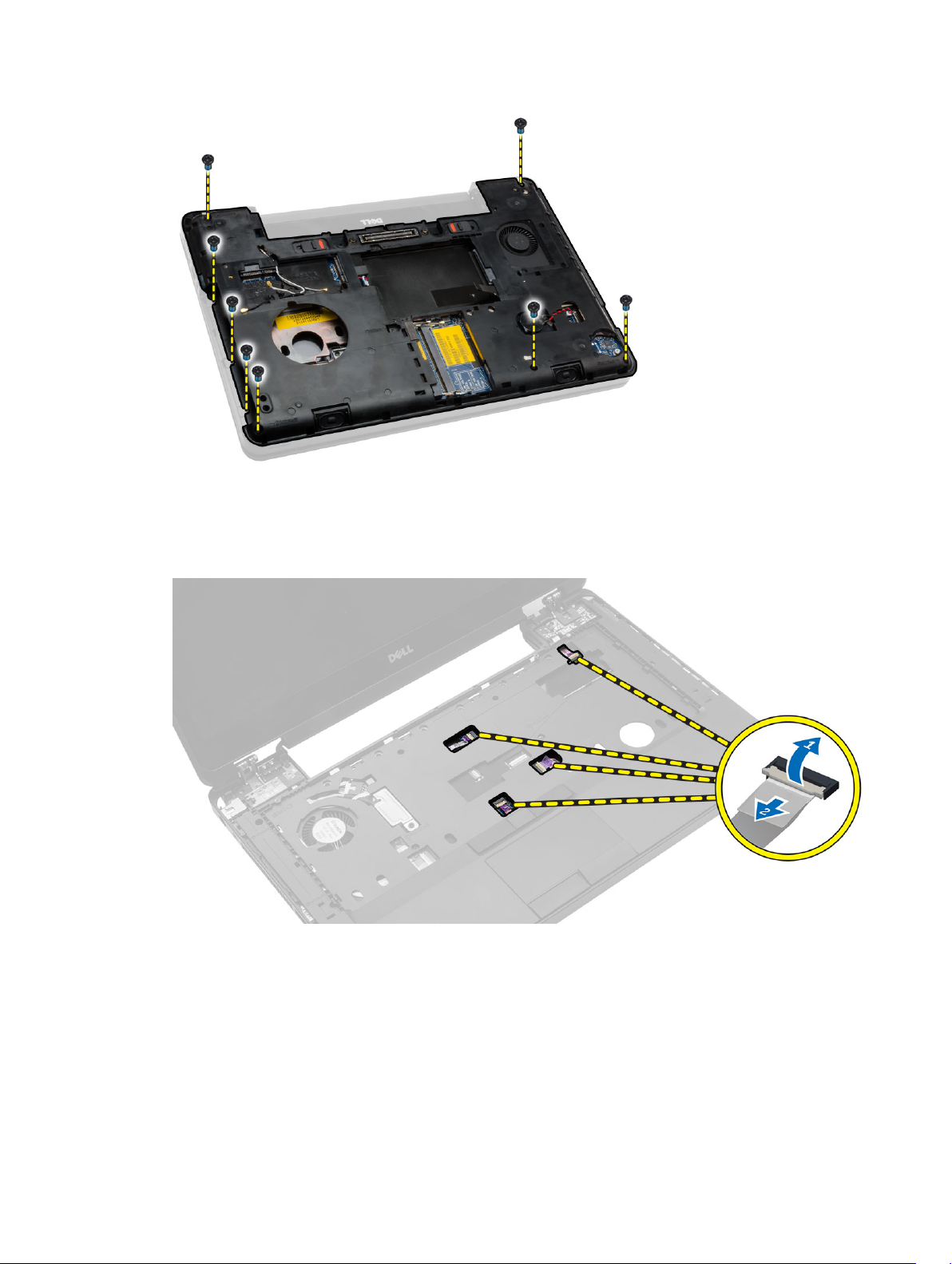
4. Disconnect:
a. media-buttons cable
b. touch-pad cable
c. fingerprint-scanner cable
d. power-button cable
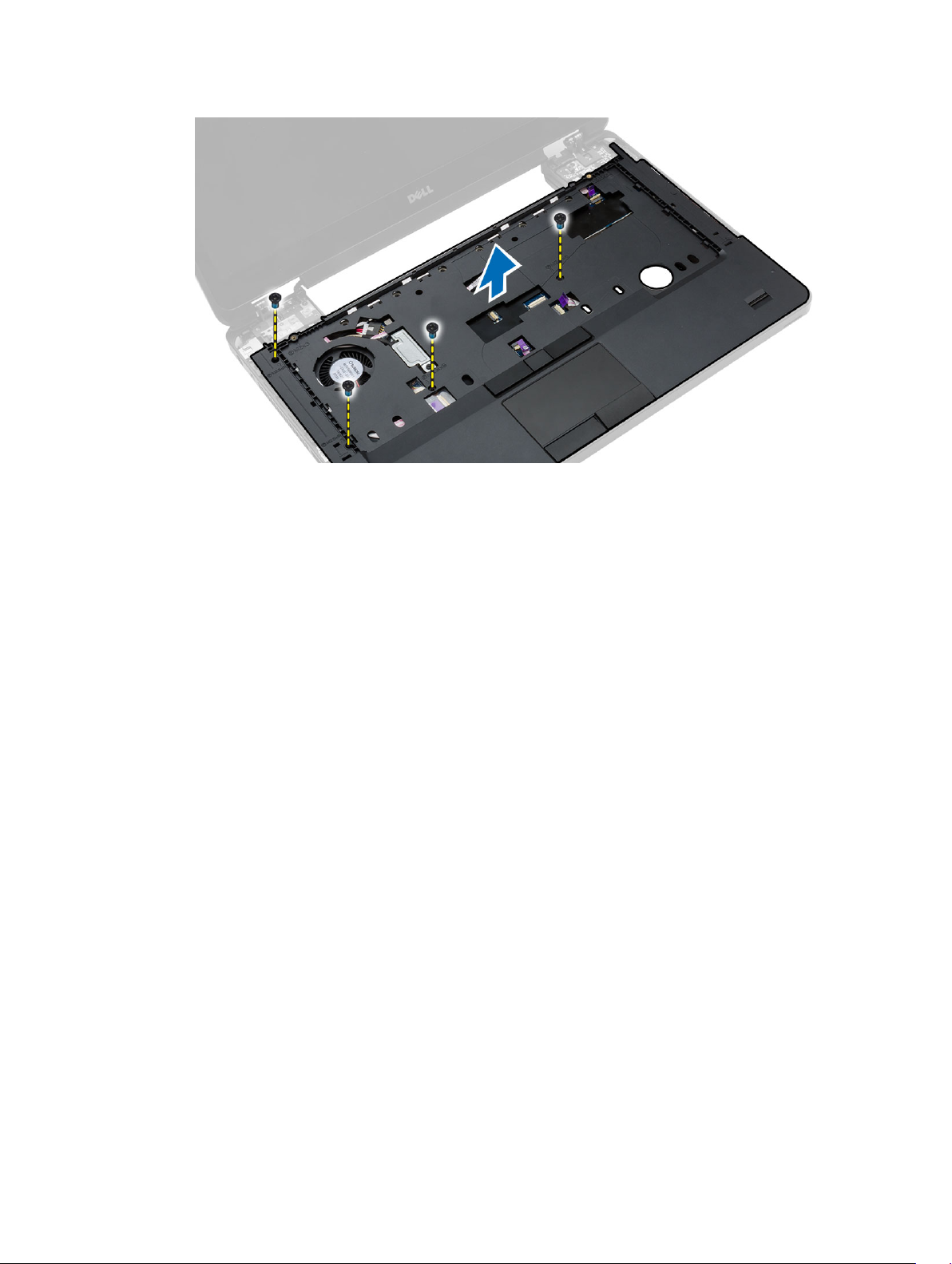
5. Perform the following steps:
a. Remove the screws that secure the palmrest of the computer.
b. Lift and remove the palmrest from the computer
25
Page 26
Installing the Palmrest
1. Align the palmrest assembly to its original position in the computer and snap it into place.
2. Connect the following cables to the system board:
a. power-button cable
b. fingerprint-scanner cable
c. touch-pad cable
d. media button cable
3. Tighten the screws to secure the palmrest at the front and back of the computer.
4. Install:
a. display hinge
b. hard drive
c. optical drive
d. memory
e. keyboard
f. keyboard trim
g. base cover
h. battery
i. SD card
5. Follow the procedures in After Working Inside Your Computer.
Removing the Display Assembly
1. Follow the procedures in Before Working Inside Your Computer.
2. Remove:
a. SD card
b. battery
c. base cover
d. keyboard trim
26
Page 27
e. keyboard
f. display hinge
g. palmrest
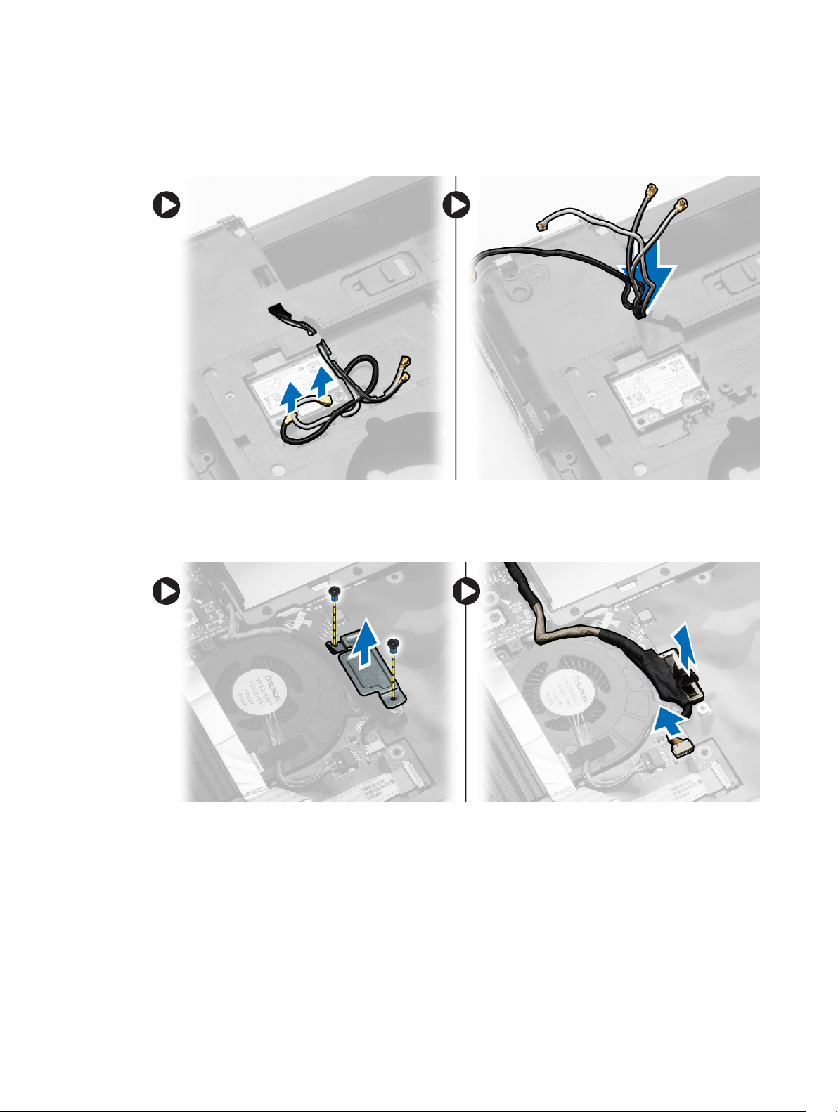
3. Disconnect and remove WLAN cable from its routing channels.
4. Perform the following steps:
a. Remove the screws that secure the display-cable connector and remove it from the system
board.
b. Disconnect the display cables from the system board.
5. Remove the screws that secure the display assembly in place and lift to remove the display assembly
from the computer.
27
Page 28
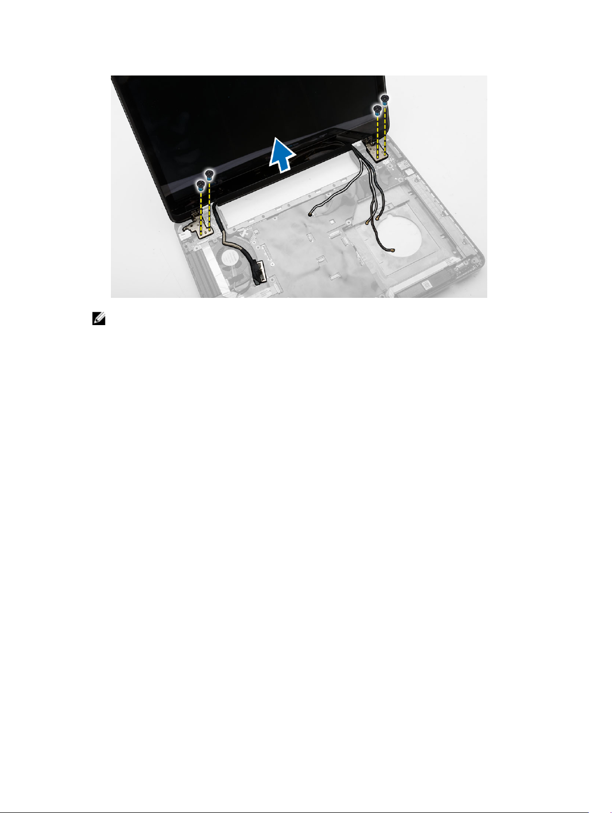
NOTE: The above display assembly removal procedures are applicable for both Touch and Nontouch versions of the computer.
Installing the Display Assembly
1. Tighten the screws that secure the display assembly in place.
2. Insert the WLAN cable through the holes on the chassis.
3. Route the display cable along its compartment and connect the display cables to its connectors on
the system board.
4. Connect the WLAN cables to their connectors.
5. Install:
a. palmrest
b. display hinge
c. keyboard
d. keyboard trim
e. base cover
f. battery
g. SD card
6. Follow the procedures in After Working Inside Your Computer.
Removing the ExpressCard Cage
1. Follow the procedures in Before Working Inside Your Computer.
2. Remove:
a. SD card
b. battery
c. base cover
d. keyboard trim
e. keyboard
28
Page 29
f. display hinge
g. palmrest
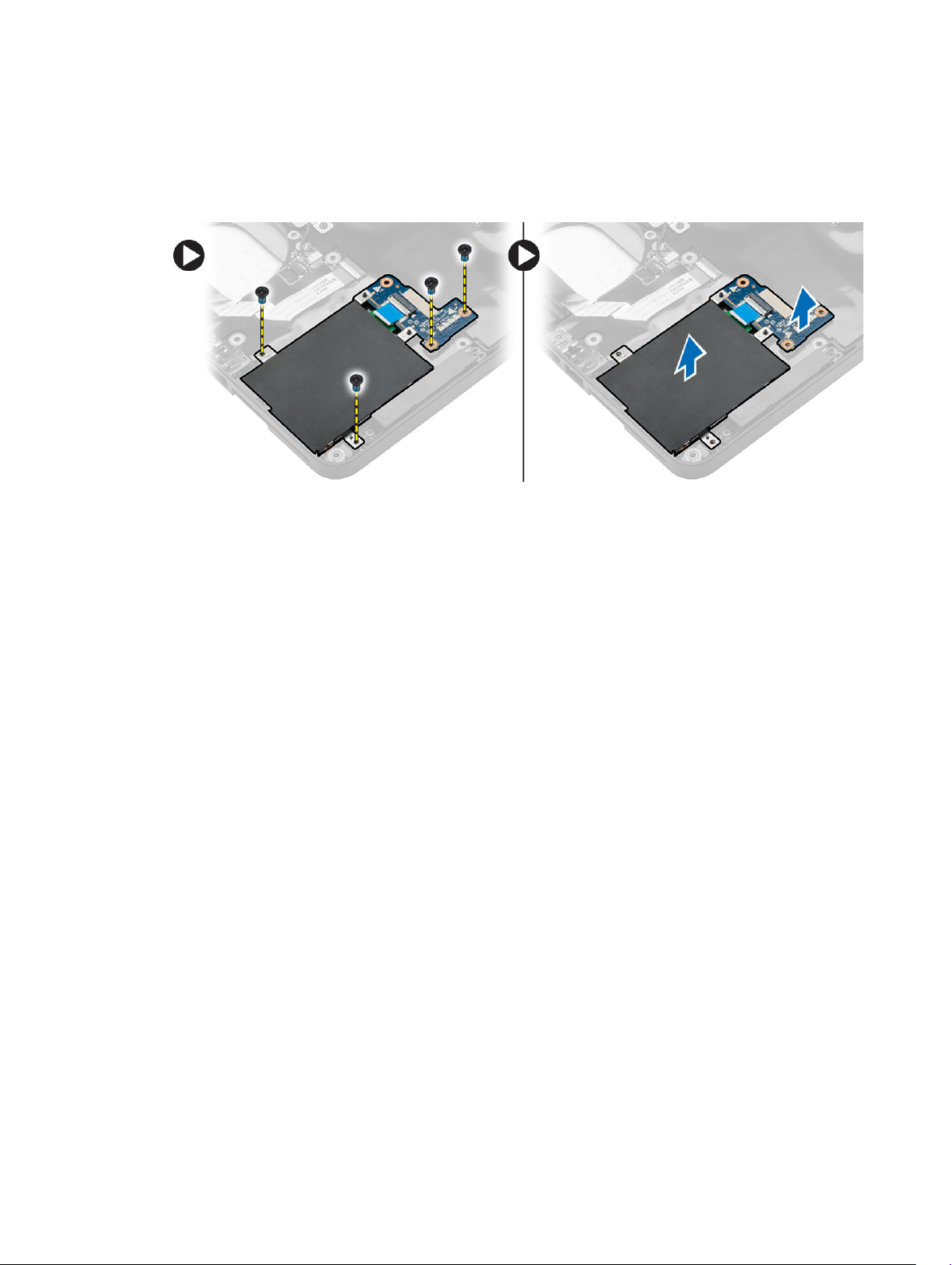
3. Perform the following steps:
a. Remove the screws that secure the ExpressCard cage.
b. Lift and remove the ExpressCard cage from the computer.
Installing the ExpressCard Cage
1. Align the ExpressCard cage to its original position on the computer and snap it into place.
2. Install the screws that secure the ExpressCard cage to the system board.
3. Install:
a. palmrest
b. display hinge
c. keyboard
d. keyboard trim
e. base cover
f. battery
g. SD card
4. Follow the procedures in After Working Inside Your Computer.
Removing the System Fan
1. Follow the procedures in Before Working Inside Your Computer.
2. Remove:
a. SD card
b. battery
c. base cover
d. keyboard trim
e. keyboard
f. memory
g. optical drive
h. hard drive
i. display hinge
j. palmrest
29
Page 30
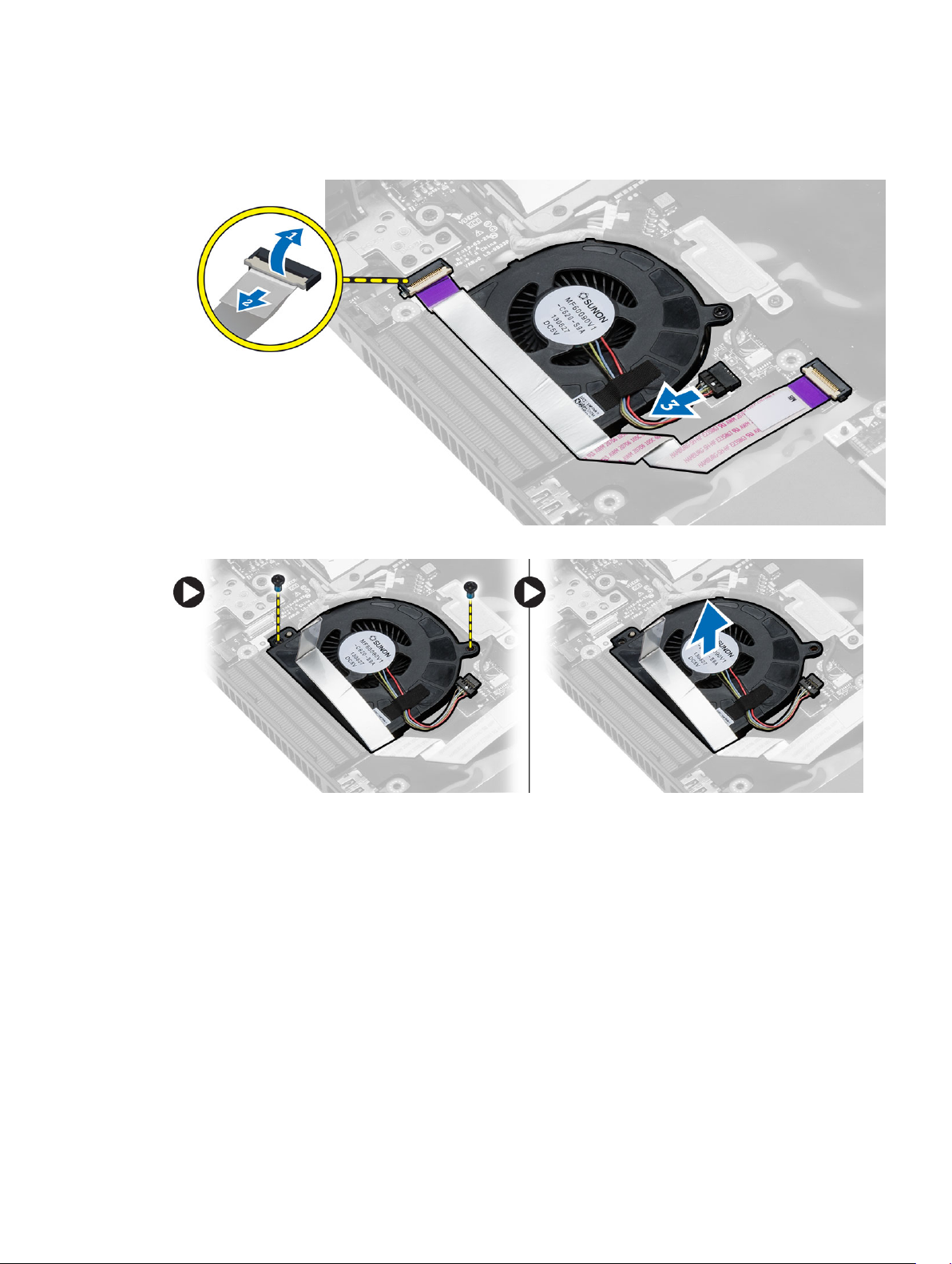
3. Disconnect:
a. system-fan cable
b. I/O board cable
4. Remove the screws that secure the system fan and lift the system fan to remove from the computer.
Installing the System Fan
1. Place the system fan on the computer.
2. Connect the system-fan cable to the system board.
3. Connect the I/O board cable to its connector.
4. Tighten the screws to secure the system fan on the computer.
5. Install:
a. palmrest
b. display hinge
c. memory
d. hard drive
e. optical drive
30
Page 31
f. keyboard
g. keyboard trim
h. base cover
i. battery
j. SD card
6. Follow the procedures in After Working Inside Your Computer.
Removing the System Board
1. Follow the procedures in Before Working Inside Your Computer.
2. Remove:
a. SD card
b. battery
c. base cover
d. keyboard trim
e. keyboard
f. memory
g. optical drive
h. hard drive
i. WLAN card
j. display hinge
k. palmrest
l. system fan
m. ExpressCard cage
3. Disconnect:
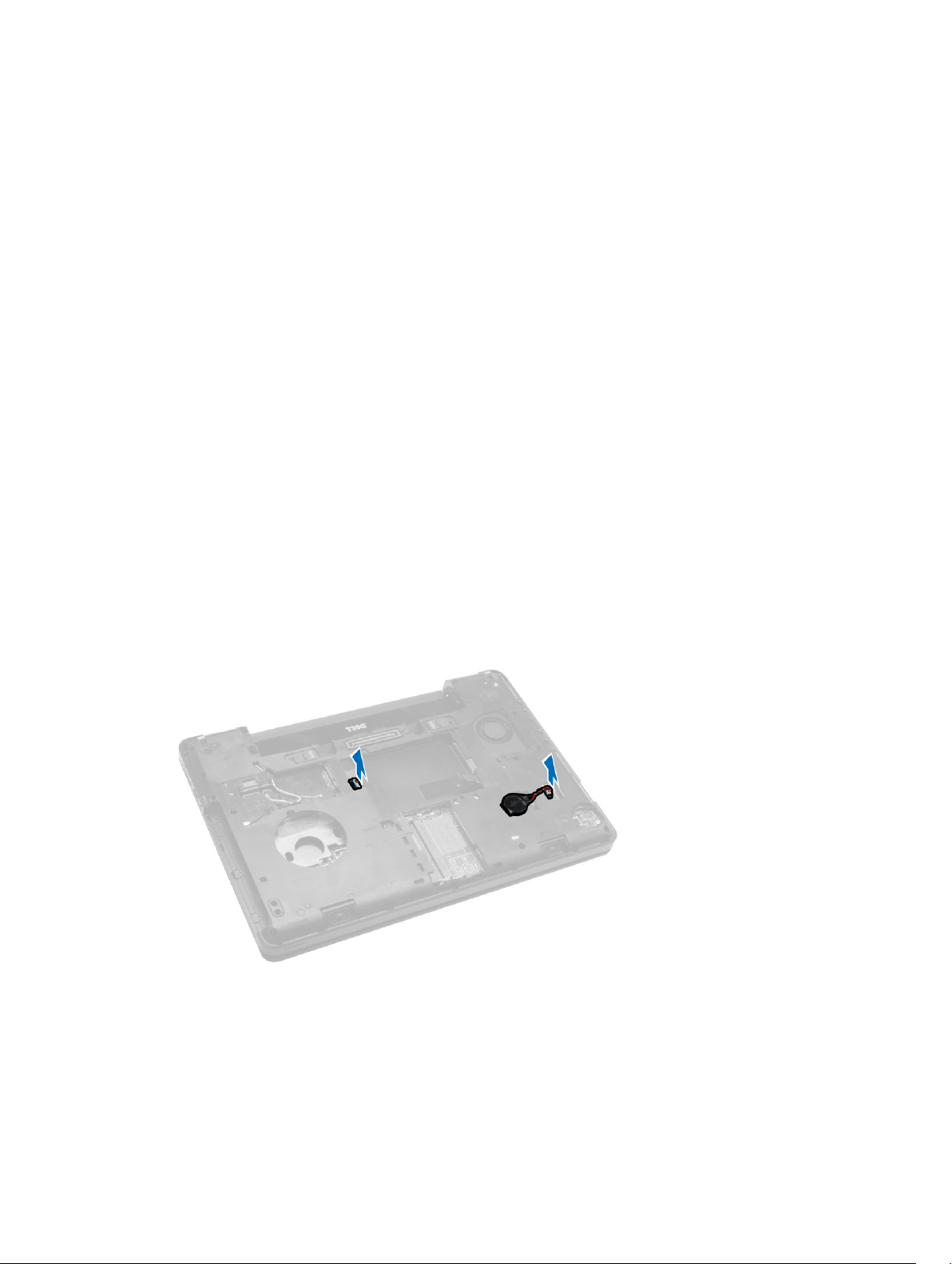
a. coin-cell battery cable
b. speaker cable
4. Flip the computer and disconnect:
a. power cable
b. status-light board cable
c. I/O board cable
31
Page 32
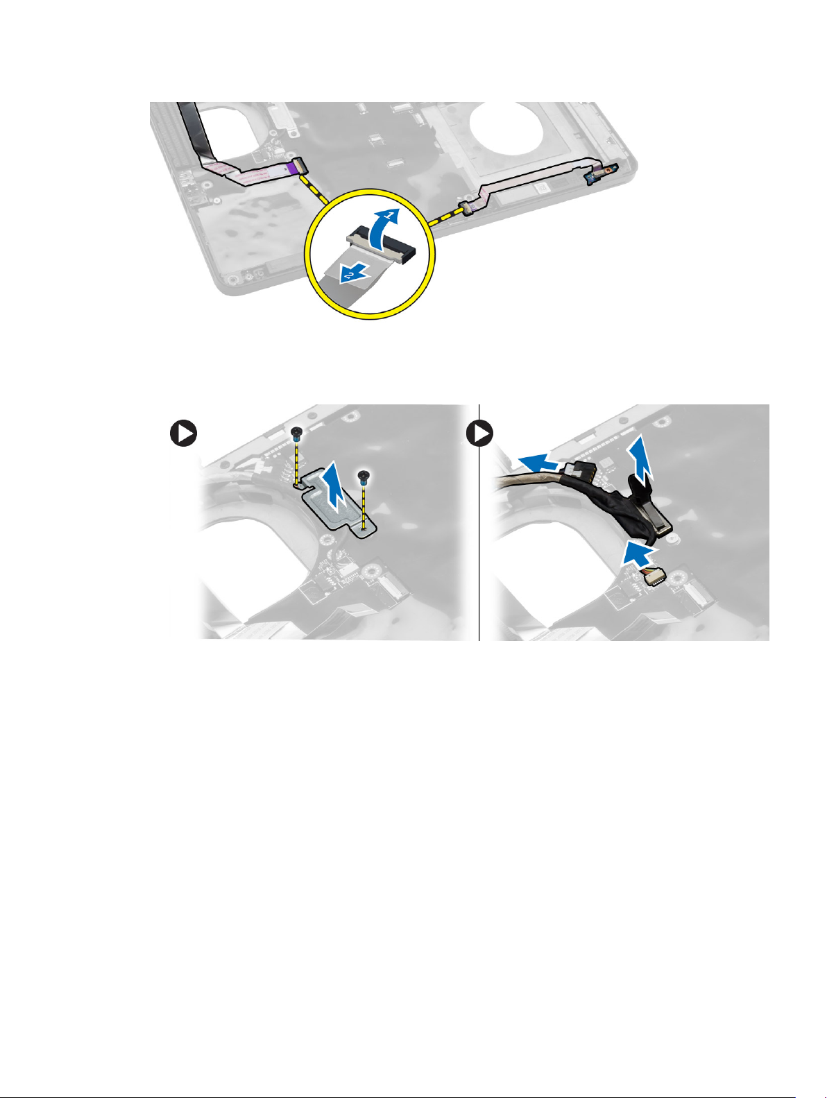
5. Perform the following steps:
a. Remove the screws that secure the display-cable connector and remove it from the system
board.
b. Disconnect the display cables and power-connector cable from the system board.
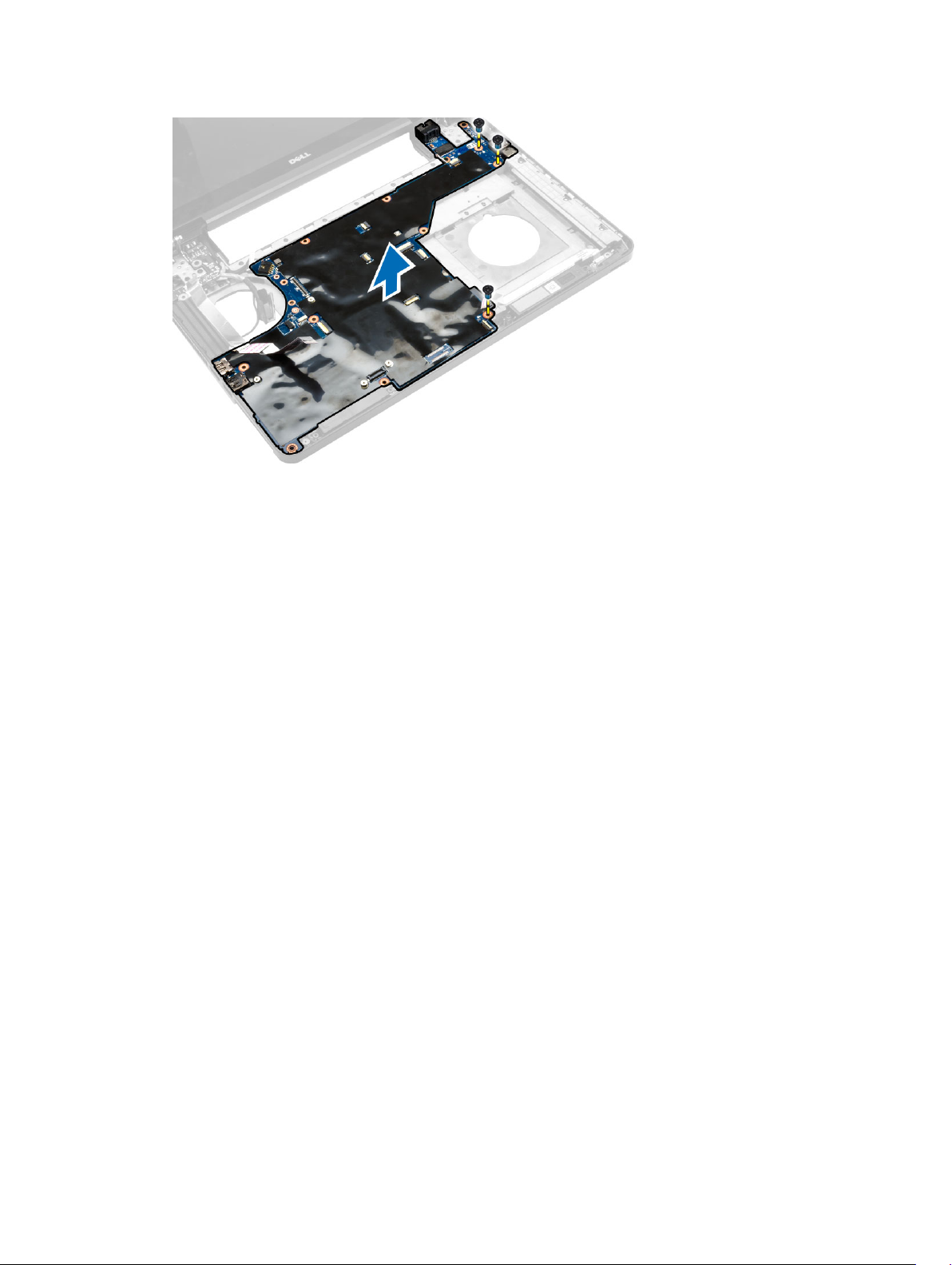
6. Remove the screws that secure the system board and lift the system board to remove from the
computer.
32
Page 33
Installing the System Board
1. Align the system board into its original position on the computer.
2. Replace and tighten the screws to secure the system board to the computer.
3. Connect the following cables:
a. I/O board cable
b. power-connector cable
c. status-light board cable
4. Turn over the computer and connect the coin-cell battery cable and speaker cable to the system
board.
5. Install:
a. ExpressCard cage
b. system fan
c. palmrest
d. display hinge
e. WLAN card
f. hard drive
g. optical drive
h. memory
i. keyboard
j. keyboard trim
k. base cover
l. battery
m. SD card
6. Follow the procedures in After Working Inside Your Computer.
33
Page 34
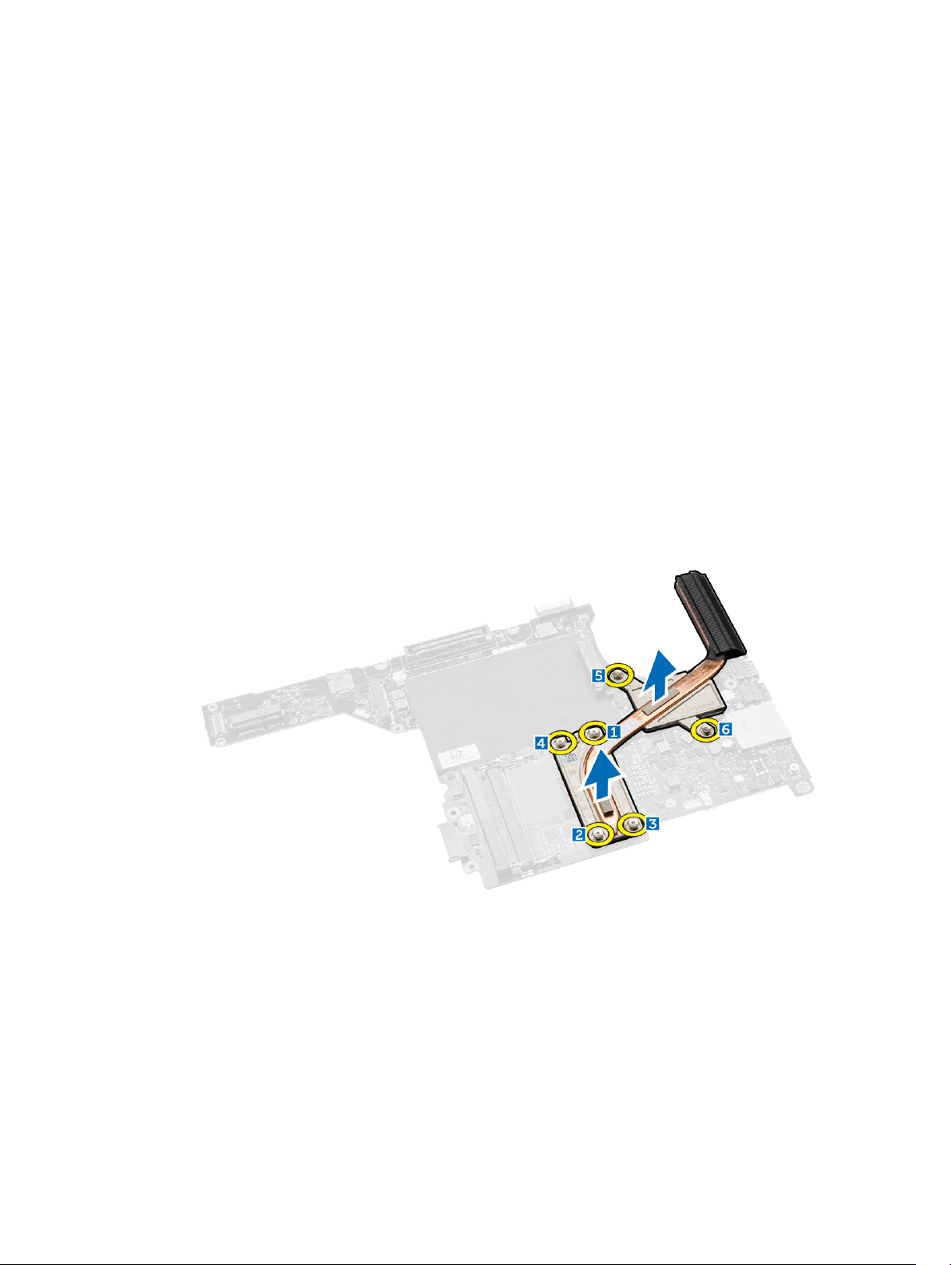
Removing the Heatsink
1. Follow the procedures in Before Working Inside Your Computer.
2. Remove:
a. SD card
b. battery
c. base cover
d. keyboard trim
e. keyboard
f. memory
g. optical drive
h. hard drive
i. WLAN card
j. display hinge
k. palmrest
l. system fan
m. ExpressCard cage
n. system board
3. Perform the following steps:
a. Remove the screws that secure the heatsink in place.
b. Lift to remove the heatsink from the computer.
Installing the Heatsink
1. Place the heatsink on the system board.
2. Tighten the screws to secure the heatsink to the computer.
3. Install:
a. system board
b. ExpressCard cage
34
Page 35
c. system fan
d. palmrest
e. display hinge
f. WLAN card
g. hard drive
h. optical drive
i. memory
j. keyboard
k. keyboard trim
l. base cover
m. battery
n. SD card
4. Follow the procedures in After Working Inside Your Computer.
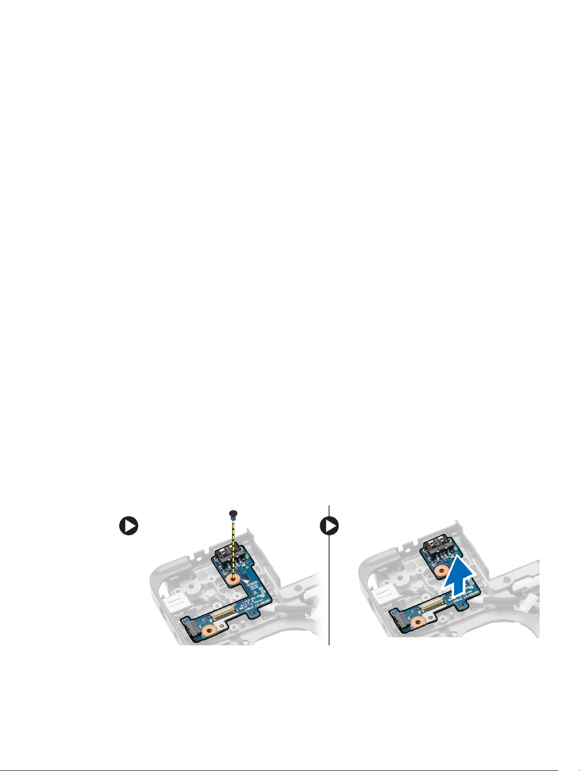
Removing the I/O Board (Left)
1. Follow the procedures in Before Working Inside Your Computer.
2. Remove:
a. SD card
b. battery
c. base cover
d. keyboard trim
e. keyboard
f. memory
g. optical drive
h. hard drive
i. WLAN card
j. display hinge
k. palmrest
l. system fan
m. ExpressCard cage
n. system board
3. Perform the following steps:
a. Remove the screw that secures the left I/O board on the computer.
b. Lift the I/O board and remove from the computer.
35
Page 36

Installing the I/O Board (Left)
1. Place the I/O board on the computer.
2. Tighten the screw to secure the I/O board to the computer.
3. Install:
a. system board
b. ExpressCard cage
c. system fan
d. palmrest
e. display hinge
f. WLAN card
g. hard drive
h. optical drive
i. memory
j. keyboard
k. keyboard trim
l. base cover
m. battery
n. SD card
4. Follow the procedures in After Working Inside Your Computer.
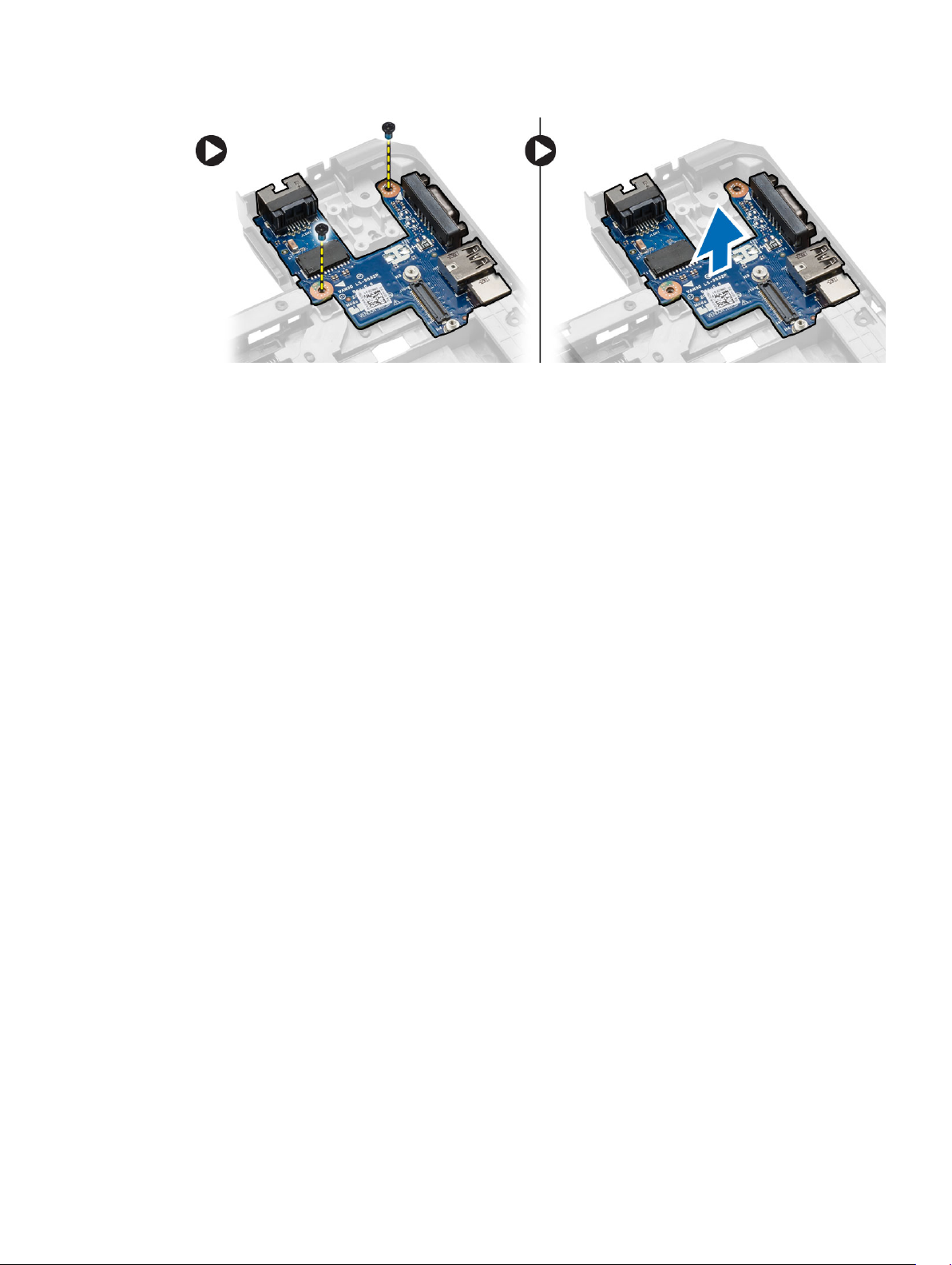
Removing the I/O Board (Right)
1. Follow the procedures in Before Working Inside Your Computer.
2. Remove:
a. SD card
b. battery
c. base cover
d. keyboard trim
e. keyboard
f. memory
g. optical drive
h. hard drive
i. WLAN card
j. display hinge
k. palmrest
l. system fan
m. ExpressCard cage
n. system board
3. Perform the following steps:
a. Remove the screws that secure the I/O board on the computer.
b. Lift the I/O board and remove from the computer.
36
Page 37
Installing the I/O Board (Right)
1. Place the I/O board on the computer.
2. Tighten the screws to secure the I/O board to the computer.
3. Install:
a. system board
b. ExpressCard cage
c. system fan
d. palmrest
e. display hinge
f. WLAN card
g. hard drive
h. optical drive
i. memory
j. keyboard
k. keyboard trim
l. base cover
m. battery
n. SD card
4. Follow the procedures in After Working Inside Your Computer.
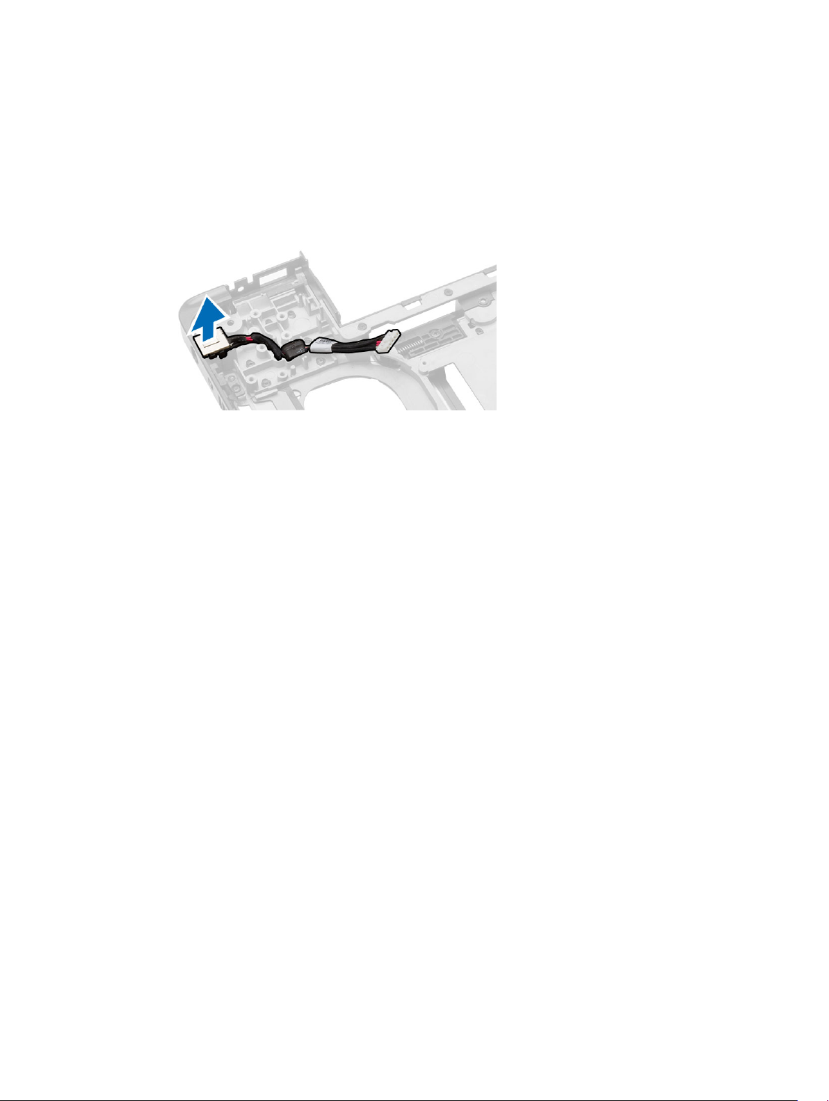
Removing the Power Connector
1. Follow the procedures in Before Working Inside Your Computer.
2. Remove:
a. SD card
b. battery
c. base cover
d. keyboard trim
e. keyboard
f. memory
g. hard drive
h. optical drive
i. WLAN card
37
Page 38
j. display hinge
k. palmrest
l. ExpressCard cage
m. system fan
n. system board
3. Perform the following steps:
a. Remove the power-connector cable from the routing channels.
b. Lift and remove the power connector from the computer.
Installing the Power Connector
1. Place the power connector on its place in the computer.
2. Route the power-connector cable on its routing channels.
3. Install:
a. system board
b. system fan
c. ExpressCard cage
d. palmrest
e. display hinge
f. WLAN card
g. hard drive
h. optical drive
i. memory
j. keyboard
k. keyboard trim
l. base cover
m. battery
n. SD card
4. Follow the procedures in After Working Inside Your Computer.
Removing the Speakers
1. Follow the procedures in Before Working Inside Your Computer.
2. Remove:
a. SD memory card
b. battery
c. base cover
38
Page 39
d. keyboard trim
e. keyboard
f. memory
g. optical drive
h. hard drive
i. WLAN card
j. display hinge
k. palmrest
l. system fan
m. ExpressCard cage
n. system board
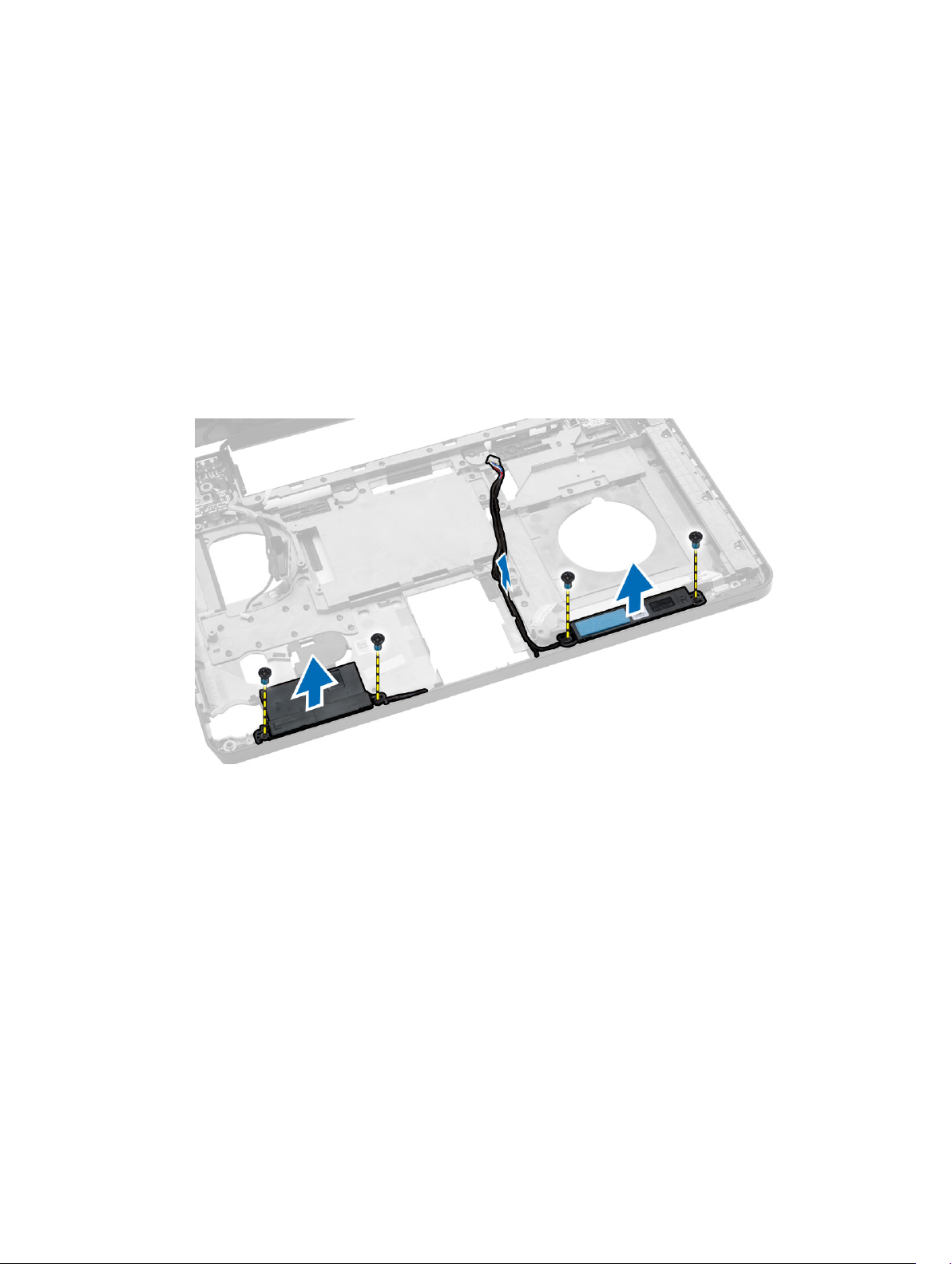
3. Perform the following steps:
a. Remove the speaker cable from the routing channels.
b. Remove the screws that secure the speakers from the computer.
c. Lift and remove the speakers from the computer.
Installing the Speakers
1. Place the speakers on the computer.
2. Secure the speaker cable to the routing channels.
3. Tighten the screws to secure the speakers to the computer.
4. Install:
a. system board
b. ExpressCard cage
c. system fan
d. palmrest
e. display hinge
f. WLAN card
g. hard drive
h. optical drive
39
Page 40
i. memory
j. keyboard
k. keyboard trim
l. base cover
m. battery
n. SD card
5. Follow the procedures in After Working Inside Your Computer.
Removing the Status-Light Board
1. Follow the procedures in Before Working Inside Your Computer.
2. Remove:
a. SD card
b. battery
c. base cover
d. keyboard trim
e. keyboard
f. memory
g. optical drive
h. hard drive
i. WLAN card
j. display hinge
k. palmrest
l. system fan
m. ExpressCard cage
n. system board
o. speakers
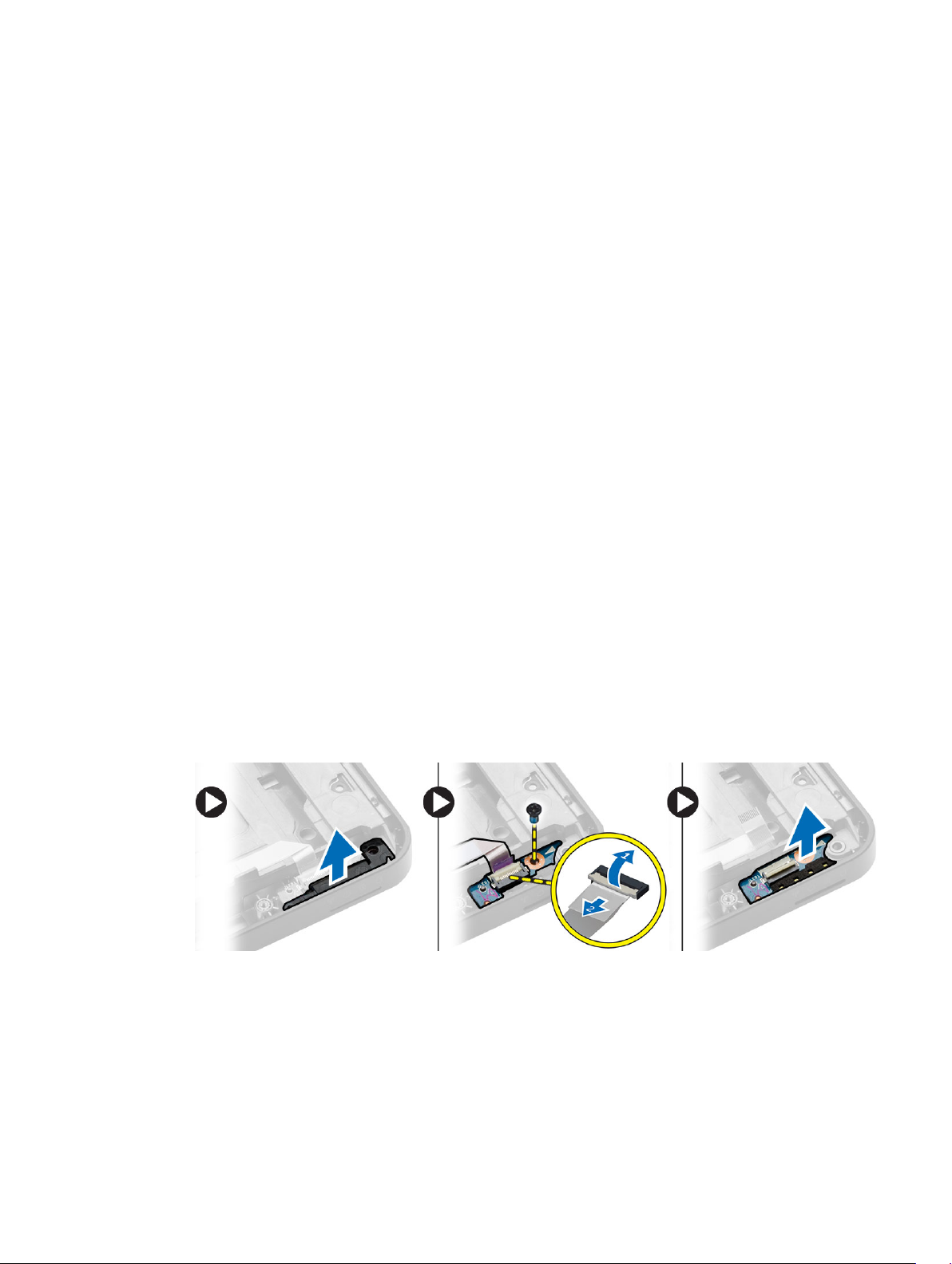
3. Perform the following steps:
a. Remove the LED cover.
b. Disconnect the status-light board cable and remove the screw that secures the status-light
board.
c. Lift and remove the status-light board from the computer.
Installing the Status-Light Board
1. Place the status-light board on its place on the computer.
2. Connect the status-light board cable to its connector.
3. Tighten the screw to secure the status-light board on the computer.
40
Page 41

4. Place the LED cover on the status-light board.
5. Install:
a. speakers
b. system board
c. system fan
d. ExpressCard cage
e. palmrest
f. display hinge
g. WLAN card
h. hard drive
i. optical drive
j. memory
k. keyboard
l. keyboard trim
m. base cover
n. battery
o. SD card
6. Follow the procedures in After Working Inside Your Computer.
41
Page 42

3
System Setup
System Setup enables you to manage your computer hardware and specify BIOS‐level options. From the
System Setup, you can:
• Change the NVRAM settings after you add or remove hardware
• View the system hardware configuration
• Enable or disable integrated devices
• Set performance and power management thresholds
• Manage your computer security
Boot Sequence
Boot Sequence allows you to bypass the System Setup‐defined boot device order and boot directly to a
specific device (for example: optical drive or hard drive). During the Power-on Self Test (POST), when the
Dell logo appears, you can:
• Access System Setup by pressing <F2> key
• Bring up the one-time boot menu by pressing <F12> key
The one-time boot menu displays the devices that you can boot from including the diagnostic option.
The boot-menu options are:
• Removable Drive (if available)
• STXXXX Drive
NOTE: XXX denotes the SATA drive number.
• Optical Drive
• Diagnostics
NOTE: Choosing Diagnostics, will display the ePSA diagnostics screen.
The boot sequence screen also displays the option to access the System Setup screen.
Navigation Keys
The following table displays the system setup navigation keys.
NOTE: For most of the system setup options, changes that you make are recorded but do not take
effect until you re-start the system.
42
Page 43

Table 1. Navigation Keys
Keys Navigation
Up arrow Moves to the previous field.
Down arrow Moves to the next field.
<Enter> Allows you to select a value in the selected field (if applicable) or follow the link in
the field.
Spacebar Expands or collapses a drop‐down list, if applicable.
<Tab> Moves to the next focus area.
NOTE: For the standard graphics browser only.
<Esc> Moves to the previous page till you view the main screen. Pressing <Esc> in the main
screen displays a message that prompts you to save any unsaved changes and
restarts the system.
<F1> Displays the System Setup help file.
System Setup Options
NOTE: Depending on the computer and its installed devices, the items listed in this section may or
may not appear.
Table 2. General
Option Description
System
Information
Battery
Information
Boot Sequence Boot Sequence Allows you to change the order in which
This section lists the primary hardware features of your computer.
• System Information: Displays BIOS Version, Service Tag, Asset Tag, Ownership
Tag, Ownership Date, Manufacture Date, and the Express Service Code.
• Memory Information: Displays Memory Installed, Memory Available, Memory
Speed, Memory Channels Mode, Memory Technology, DIMM ASize, DIMM B Size,
• Processor Information: Displays Processor Type, Core Count, Processor ID,
Current Clock Speed, Minimum Clock Speed, Maximum Clock Speed, Processor
L2 Cache, Processor L3 Cache, HT Capable, and 64-Bit Technology.
• Device Information: Displays Primary Hard Drive, MiniCard Device, ODD Device,
Dock eSATA Device, LOM MAC Address, Video Controller, Video BIOS Version,
Video Memory, Panel Type, Native Resolution, Audio Controller, Wi-Fi Device,
WiGig Device, Cellular Device, Bluetooth Device.
Displays the battery status and the type of AC adapter connected to the computer
the computer attempts to find an
operating system. The options are:
• Diskette Drive
• Internal HDD
• USB Storage Device
• CD/DVD/CD-RW Drive
• Onboard NIC
43
Page 44

Option Description
Boot List Option Allows you to change the boot list option.
By default, all the options are checked.
You can also deselect any option or
change the boot order.
• Legacy
• UEFI
Advanced Boot
Options
This option allows you the legacy option ROMs to load. By default, the Enable Legacy
Option ROMs is unchecked.
Date/Time Allows you to change the date and time.
Table 3. System Configuration
Option Description
Integrated NIC Allows you to configure the integrated network controller. The options
are:
• Disabled
• Enabled
• Enabled w/PXE: This option is enabled by default.
Parallel Port Allows you to configure the parallel port on the docking station. The
options are:
• Disabled
• AT: This option is enabled by default.
• PS2
• ECP
Serial Port Allows you to configure the integrated serial port. The options are:
• Disabled
• COM1: This option is enabled by default.
• COM2
• COM3
• COM4
SATA Operation Allows you to configure the internal SATA hard-drive controller. The
options are:
• Disabled
• AHCI
• RAID On: This option is enabled by default.
Drives Allows you to configure the SATA drives on board. All drives are enabled
by default. The options are:
• SATA-0
• SATA-1
• SATA-2
44
Page 45

Option Description
• SATA-3
SMART Reporting This field controls whether hard drive errors for integrated drives are
reported during system startup. This technology is part of the SMART
(Self Monitoring Analysis and Reporting Technology) specification. This
option is disabled by default.
• Enable SMART Reporting
USB Configuration This field configures the integrated USB controller. If Boot Support is
enabled, the system is allowed to boot any type of USB Mass Storage
Devices (HDD, memory key, floppy).
If USB port is enabled, device attached to this port is enabled and
available for OS.
If USB port is disabled, the OS cannot see any device attached to this
port.
• Enable Boot Support
• Enable External USB Port
• Enable USB3.0 Controller
NOTE: USB keyboard and mouse always work in the BIOS setup
irrespective of these settings.
Audio This field enables or disables the integrated audio controller. By default,
the Enable Audio option is selected.
Keyboard Illumination This field lets you choose the operating mode of the keyboard
illumination feature.
The keyboard brightness level can be set from 25% to 100%
• Disabled.
• Level is 25%
• Level is 50%
• Level is 75%
• Level is 100%: This option is enabled by default
Unobtrusive Mode This option, when enabled, pressing Fn+B turns of all light and sound
emissions in the system. To resume normal operation, press Fn+B again.
This option is Disabled by default.
Miscellaneous Devices Allows you to enable or disable the following devices:
• Enable Microphone
• Enable Camera
• Enable Express card
• Enable Hard Drive Free Fall Protection
• Enable Media Card
• Disable Media Card
NOTE: All devices are enabled by default.
45
Page 46
Option Description
You can also enable or disable Media Card.
Table 4. Video
Option Description
LCD Brightness Allows you to set the display brightness depending up on the power
source (On Battery and On AC).
NOTE: The Video setting will only be visible when a video card is installed into the system.
Table 5. Security
Option Description
Admin Password Allows you to set, change, or delete the administrator (admin) password.
NOTE: You must set the admin password before you set the system
or hard drive password. Deleting the admin password automatically
deletes the system password and the hard drive password.
NOTE: Successful password changes take effect immediately.
Default Setting: Not set
System Password Allows you to set, change or delete the system password.
NOTE: Successful password changes take effect immediately.
Default Setting: Not set
Internal HDD-1 Password Allows you to set or change the system's internal hard-disk drive.
NOTE: Successful password changes take effect immediately.
Default Setting: Not set
Strong Password Allows you to enforce the option to always set strong passwords.
Default Setting: Enable Strong Password is not selected.
NOTE: If Strong Password is enabled, Admin and System passwords
must contain at least one uppercase character, one lowercase
character and be at least 8 characters long.
Password Configuration Allows you to determine the minimum and maximum length of
Administrator and System passwords.
Password Bypass Allows you to enable or disable the permission to bypass the System and
the Internal HDD password, when they are set. The options are:
• Disabled
• Reboot bypass
46
Page 47

Option Description
Default Setting: Disabled
Password Change Allows you to enable the disable permission to the System and Hard
Drive passwords when the admin password is set.
Default Setting: Allow Non-Admin Password Changes is selected
Non-Admin Setup Changes Allows you to determine whether changes to the setup options are
allowed when an Administrator Password is set. If disabled the setup
options are locked by the admin password.
TPM Security Allows you to enable the Trusted Platform Module (TPM) during POST.
Default Setting: The option is disabled.
Computrace Allows you to activate or disable the optional Computrace software The
options are:
• Deactivate
• Disable
• Activate
NOTE: The Activate and Disable options will permanently activate or
disable the feature and no further changes will be allowed
Deactivate (default)
CPU XD Support Allows you to enable the Execute Disable mode of the processor.
Enable CPU XD Support (default)
OROM Keyboard Access Allows you to set an option to enter the Option ROM Configuration
screens using hotkeys during boot. The options are:
• Enable
• One Time Enable
• Disable
Default Setting: Enable
Admin Setup Lockout Allows you to prevent users from entering Setup when an Administrator
password is set.
Default Setting: Enable Admin Setup Lockout is not selected.
Table 6. Secure Boot
Option Description
Secure Boot Enable This option enables or disables the Secure Boot Feature.
• Disable (default)
47
Page 48

Option Description
• Enable
Expert Key Management Allows you to manipulate the security key databases only if the system is
in Custom Mode. The Enable Custom Mode option is disabled by
default. The options are:
• PK
• KEK
• db
• dbx
If you enable the Custom Mode, the relevant options for PK, KEK, db,
and dbx appear. The options are:
• Save to File- Saves the key to a user-selected file
• Replace from File- Replaces the current key with a key from a user-
selected file
• Append from File- Adds a key to the current database from a user-
selected file
• Delete- Deletes the selected key
• Reset All Keys- Resets to default setting
• Delete All Keys- Deletes all the keys
NOTE: If you disable the Custom Mode, all the changes made will
be erased and the keys will restore to default settings.
Table 7. Performance
Option Description
Multi Core Support This field specifies whether the process will have one or all cores
enabled. The performance of some applications will improve with the
additional cores. This option is enabled by default.Allows you to enable
or disable multi-core support for the processor. The options are:
• All
• 1
• 2
Default Setting: All
Intel SpeedStep Allows you to enable or disable the Intel SpeedStep feature.
Default Setting: Enable Intel SpeedStep
C States Control Allows you to enable or disable the additional processor sleep states.
Default Setting: The option C states is enabled.
Intel TurboBoost Allows you to enable or disable the Intel TurboBoost mode of the
processor.
Default Setting: Enable Intel TurboBoost
48
Page 49

Option Description
Hyper-Thread Control Allows you to enable or disable the HyperThreading in the processor.
Default Setting: Enabled
Rapid Start Technology This option might improve the battery life by automatically putting the
computer in to a low power state during Sleep, after a user-specified
amount of time.
Default Setting: Disabled
Table 8. Power Management
Option Description
AC Behavior Allows you to enable or disable the computer from turning on
automatically when an AC adapter is connected.
Default Setting: Wake on AC is not selected.
Auto On Time Allows you to set the time at which the computer must turn on
automatically. The options are:
• Disabled (default)
• Every Day
• Weekdays
• Select Days
USB Wake Support Allows you to enable USB devices to wake the system from Standby.
NOTE: This feature is only functional when the AC power adapter is
connected. If the AC power adapter is removed during Standby, the
system setup will remove power from all of the USB ports to
conserve battery power.
• Enable USB Wake Support
• DEnable USB Wake Support is not selected
Wireless Radio Control Allows you to enable or disable the feature that automatically switches
from wired or wireless networks without depending on the physical
connection.
• Control WLAN Radio
• Control WWAN Radio
• Control WLAN radio or Control WWAN radio is not selected (default)
Wake on LAN/WLAN Allows you to enable or disable the feature that powers on the computer
from the Off state when triggered by a LAN signal.
• Disabled: This option is enabled by default
• LAN Only
• WLAN Only
• LAN or WLAN
• LAN with PXE Boot
49
Page 50

Option Description
Block Sleep This option lets you block entering to sleep (S3 state) in Operating
System environment.
Block Sleep (S3 state) - This option is disabled by default.
Peak Shift This option enables you to minimize the AC power consumption during
the peak power times of day. After you enable this option, your system
runs only in battery even if the AC is attached.
Advanced Battery Charge
Configuration
Primary Battery Charge
Configuration
Battery Slice Charge
Configuration
This option enables you to maximize the battery health. By enabling this
option, your system uses the standard charging algorithm and other
techniques, during the non-work hours to improve the battery health.
Disabled (default)
Allows you to select the charging mode for the battery. The options are:
• Adaptive
• Standard
• ExpressCharge: This option is enabled by default.
• Primarily AC use
• Custom
If Custom Charge is selected, you can also configure Custom Charge
Start and Custom Charge Stop.
NOTE: All charging mode may not be available for all the batteries.
To enable this option, disable the Advanced Battery Charge
Configuration option.
Allows you to select the type of charge for the battery. The options are:
• Standard Charge
• Express Charge : This option is enabled by default.
NOTE: Express charge may not be available for all the batteries. To
enable this option, disable the Advanced Battery Charge
Configuration option.
Intel Smart Connect
Technology
This option, if enabled, periodically senses the nearby wireless
connections, while the system is in sleep state. You can use this option
to synchronize the email or other social media application that are open,
when the system enters the sleep state.
Table 9. POST Behavior
Option Description
Adapter Warnings Allows you to enable or disable the system setup (BIOS) warning
messages when you use certain power adapters.
Default Setting: Enable Adapter Warnings
Keypad (Embedded) Allows you to choose one of two methods to enable the keypad that is
embedded in the internal keyboard.
50
Page 51

Option Description
• Fn Key Only: This option is enabled by default.
• By Numlock
NOTE: The Keyboard (Embedded) option is not supported in
Latitude E5540
Mouse/Touchpad Allows you to define how the system handles mouse and touch pad
input. The options are:
• Serial Mouse
• PS2 Mouse
• Toushpad/PS-2 Mouse: This option is enabled by default.
Numlock Enable Allows you to enable the Numlock option when the computer boots.
Enable Network (default)
Fn Key Emulation Allows you to set the option where the <Scroll Lock> key is used to
simulate the <Fn> key feature.
Enable Fn Key Emulation (default)
Mebx Hotkey Allows you to specify whether the MEBx Hotkey function should be
enabled when the system boots
Enable MEBx Hotkey (default)
Fastboot Allows you to speed up the boot process by bypassing some of the
compatibility steps. The options are:
• Minimal
• Thorough (default)
• Auto
Extended BIOS POST Time Allows you to create an additional pre-boot delay. The options are:
• 0 seconds
• 5 seconds (default)
• 10 seconds
Table 10. Virtualization Support
Option Description
Virtualization Allows you to enable or disable the Intel Virtualization Technology.
Enable Intel Virtualization Technology (default)
VT for Direct I/O Enables or disables the Virtual Machine Monitor (VMM) from utilizing the
additional hardware capabilities provided by Intel® Virtualization
technology for direct I/O.
Enable VT for Direct I/O — enabled by default.
51
Page 52

Option Description
Trusted Execution This option specifies whether a Measured Virtual Machine Monitor
(MVMM) can utilize the additional hardware capabilities provided by Intel
Trusted Execution Technology. The TPM virtualization Technology, and
Virtualization technology for direct I/O must be enabled to use this
feature.
Trusted Execution — disabled by default.
Table 11. Wireless
Option Description
Wireless Switch Allows to set the wireless devices that can be controlled by the wireless
switch. The options are:
Latitude
E5440
• WWAN
• WLAN
• WiGig
• Bluetooth
All the options are enabled by default.
Latitude
E5540
• WLAN
• WiGig
• Bluetooth
All the options are enabled by default.
Wireless Device Enable Allows you to enable or disable the internal wireless devices.
Latitude
E5440
• WWAN
• WLAN / WiGig
• Bluetooth
All the options are enabled by default.
Latitude
E5540
• WLAN / WiGig
• Bluetooth
All the options are enabled by default.
Table 12. Maintenance
Option Description
Service Tag Displays the Service Tag of your computer.
Asset Tag Allows you to create a system asset tag if an asset tag is not already set.
This option is not set by default.
52
Page 53

Table 13. System Logs
Option Description
BIOS Events Allows you to view and clear the System Setup (BIOS) POST events.
Thermal Events Allows you to view and clear the System Setup (Thermal) events.
Power Events Allows you to view and clear the System Setup (Power) events.
Updating the BIOS
It is recommended to update your BIOS (system setup), on replacing the system board or if an update is
available. For laptops, ensure that your computer battery is fully charged and connected to a power
outlet
1. Re-start the computer.
2. Go to dell.com/support.
3. Enter the Service Tag or Express Service Code and click Submit.
NOTE: To locate the Service Tag, click Where is my Service Tag?
NOTE: If you cannot find your Service Tag, click Detect My Product. Proceed with the
instructions on screen.
4. If you are unable to locate or find the Service Tag, click the Product Category of your computer.
5. Choose the Product Type from the list.
6. Select your computer model and the Product Support page of your computer appears.
7. Click Get drivers and click View All Drivers.
The Drivers and Downloads page opens.
8. On the Drivers and Downloads screen, under the Operating System drop-down list, select BIOS.
9. Identify the latest BIOS file and click Download File.
You can also analyze which drivers need an update. To do this for your product, click Analyze
System for Updates and follow the instructions on the screen.
10. Select your preferred download method in the Please select your download method below window,
click Download File.
The File Download window appears.
11. Click Save to save the file on your computer.
12. Click Run to install the updated BIOS settings on your computer.
Follow the instructions on the screen.
System and Setup Password
You can create a system password and a setup password to secure your computer.
Password Type Description
System password Password that you must enter to log on to your system.
Setup password Password that you must enter to access and make changes to the BIOS settings of
your computer.
53
Page 54

CAUTION: The password features provide a basic level of security for the data on your computer.
CAUTION: Anyone can access the data stored on your computer if it is not locked and left
unattended.
NOTE: Your computer is shipped with the system and setup password feature disabled.
Assigning a System Password and Setup Password
You can assign a new System Password and/or Setup Password or change an existing System Password
and/or Setup Password only when Password Status is Unlocked. If the Password Status is Locked, you
cannot change the System Password.
NOTE: If the password jumper is disabled, the existing System Password and Setup Password are
deleted and you need not provide the system password to log on to the computer.
To enter a system setup, press <F2> immediately after a power-on or re-boot.
1. In the System BIOS or System Setup screen, select System Security and press <Enter>.
The System Security screen appears.
2. In the System Security screen, verify that Password Status is Unlocked.
3. Select System Password , enter your system password, and press <Enter> or <Tab>.
Use the following guidelines to assign the system password:
• A password can have up to 32 characters.
• The password can contain the numbers 0 through 9.
• Only lower case letters are valid, upper case letters are not allowed.
• Only the following special characters are allowed: space, (”), (+), (,), (-), (.), (/), (;), ([), (\), (]), (`).
Re-enter the system password when prompted.
4. Type the system password that you entered earlier and click OK.
5. Select Setup Password, type your system password and press <Enter> or <Tab>.
A message prompts you to re-type the setup password.
6. Type the setup password that you entered earlier and click OK.
7. Press <Esc> and a message prompts you to save the changes.
8. Press <Y> to save the changes.
The computer reboots.
Deleting or Changing an Existing System and/or Setup Password
Ensure that the Password Status is Unlocked (in the System Setup) before attempting to delete or change
the existing System and/or Setup password. You cannot delete or change an existing System or Setup
password, if the Password Status is Locked.
To enter the System Setup, press <F2> immediately after a power-on or reboot.
1. In the System BIOS or System Setup screen, select System Security and press <Enter>.
The System Security screen is displayed.
2. In the System Security screen, verify that Password Status is Unlocked.
3. Select System Password, alter or delete the existing system password and press <Enter> or <Tab>.
4. Select Setup Password, alter or delete the existing setup password and press <Enter> or <Tab>.
54
Page 55

NOTE: If you change the System and/or Setup password, re-enter the new password when
promoted. If you delete the System and/or Setup password, confirm the deletion when
promoted.
5. Press <Esc> and a message prompts you to save the changes.
6. Press <Y> to save the changes and exit from the System Setup.
The computer reboots.
55
Page 56

4
Diagnostics
If you experience a problem with your computer, run the ePSA diagnostics before contacting Dell for
technical assistance. The purpose of running diagnostics is to test your computer's hardware without
requiring additional equipment or risking data loss. If you are unable to fix the problem yourself, service
and support personnel can use the diagnostics results to help you solve the problem.
Enhanced Pre-Boot System Assessment (ePSA) Diagnostics
The ePSA diagnostics (also known as system diagnostics) performs a complete check of your hardware.
The ePSA is embedded with the BIOS and is launched by the BIOS internally. The embedded system
diagnostics provides a set of options for particular devices or device groups allowing you to:
• Run tests automatically or in an interactive mode
• Repeat tests
• Display or save test results
• Run thorough tests to introduce additional test options to provide extra information about the failed
device(s)
• View status messages that inform you if tests are completed successfully
• View error messages that inform you of problems encountered during testing
CAUTION: Use the system diagnostics to test only your computer. Using this program with other
computers may cause invalid results or error messages.
NOTE: Some tests for specific devices require user interaction. Always ensure that you are present
at the computer terminal when the diagnostic tests are performed.
1. Power-on the computer.
2. As the computer boots, press the <F12> key as the Dell logo appears.
3. On the boot menu screen, select the Diagnostics option.
The Enhanced Pre-boot System Assessment window is displayed, listing all devices detected in the
computer. The diagnostics starts running the tests on all the detected devices.
4. If you wish to run a diagnostic test on a specific device, press <Esc> and click Yes to stop the
diagnostic test.
5. Select the device from the left pane and click Run Tests.
6. If there are any issues, error codes are displayed.
Note the error code and contact Dell.
56
Page 57

Device Status Lights
Icon Description
Turns on when you turn on the computer and blinks when the computer is in a power
management mode.
Turns on when the computer reads or writes data.
Turns on steadily or blinks to indicate battery charge status.
Turns on when wireless networking is enabled.
Battery Status Lights
If the computer is connected to an electrical outlet, the battery light operates as follows:
Alternately
blinking amber
light and white
light
Alternately
blinking amber
light with
steady white
light
Constantly
blinking amber
light
Light off Battery in full charge mode with AC adapter present.
White light on Battery in charge mode with AC adapter present.
An unauthenticated or unsupported non-Dell AC adapter is attached to your
laptop.
Temporary battery failure with AC adapter present.
Fatal battery failure with AC adapter present.
57
Page 58

Specifications
NOTE: Offerings may vary by region. For more information regarding the configuration of your
computer, click Start (Start icon) → Help and Support, and then select the option to view
information about your computer.
Table 14. System Information
Feature Specification
DRAM bus width 64-bit
Flash EPROM SPI 32Mbits + 64Mbits
PCIe Gen1 bus 100 MHz
External Bus Frequency DMI (5GT/s)
Table 15. Processor
Feature Specification
Types
• Intel Core i3 series
• Intel Core i5 series
• Intel Core i7 series
5
L3 cache up to 8 MB
Table 16. Memory
Feature Specification
Memory connector two SoDIMM slots
Memory-module capacity per slot 4 GB, 8 GB
Memory type DDR3 SDRAM 1600 Mhz
Minimum memory 4 GB
Maximum memory 16 GB
Table 17. mSATA Support
Feature Specification
with Express Card I/O and Discrete Graphic
Configuration
for other configurations mSATA is supported on both Latitude E5440 and Latitude
58
No mSATA support on both Latitude E5440 and Latitude
E5540.
E5540.
Page 59

Feature Specification
without Express Card I/O on Discrete
Graphic and all UMA Graphic Configurations
Table 18. Audio
• Supports mSATA and WWAN on Latitude E5440
• Supports mSATA on Latitude E5540.
Feature Specification
Type four-channel high definition audio
Controller Realtek ALC3226
Stereo conversion 24-bit (analog-to-digital and digital-to-analog)
Interface:
Internal high definition audio
External microphone-in/stereo headphones/external speakers
connector
Speakers two
Internal speaker amplifier 1W (RMS) per channel
Volume controls hot keys for volume control and mute control
Table 19. Video
Feature Specification
Type integrated on system board
Controller
UMA Intel HD Graphics 4600
Discrete Nvidia GeForce (N14M-GE) Discrete Graphics Card, 2 GB
Graphics
Table 20. Communications
Feature Specification
Network adapter 10/100/1000 Mb/s Ethernet (RJ-45)
Wireless
• Internal wireless local area network (WLAN)
• Wireless wide area network (WWAN) (E5440 only)
Table 21. Ports and Connectors
Feature Specification
Audio (optional) one microphone/stereo headphone/speakers connector
Video
• one 15-pin VGA connector
• 19-pin HDMI connector
Network adapter one RJ-45 connector
59
Page 60

Feature Specification
USB 2.0
• one 4–pin USB 2.0–compliant connector (E5440)
• two 4-pin USB 2.0-compliant connectors (E5540)
NOTE: The USB 2.0 connector at the back of the
Latitude E5540 computer, gets deactivated, when the
Latitude E5540 computer is connected to the
docking station.
USB 3.0 two USB 3.0–compliant connectors
Memory card reader one 8-in-1 memory card reader
Docking port one
Subscriber Identity Module (SIM) port one (E5440 only)
Table 22. Display
Feature Specification
Type
Latitude E5440
• HD(1366x768), WLED
• HD+(1600 x 900)
Latitude E5540
• HD(1366x768), WLED
• FHD (1920 x 1080)
Size
Latitude E5440 14.0"
Latitude E5540 15.6"
Dimensions:
Latitude E5440:
Height 192.5 mm (7.57 inches)
Width 324 mm (12.75 inches)
Diagonal 355.60 mm (14.00 inches)
Active ares (X/Y) 309.40 mm x 173.95 mm
Maximum resolution
• 1366 x 768 pixels
• 1600 x 900 pixels
Maximum Brightness 200 nits
Latitude E5540:
Height 210 mm (8.26 inches)
Width 360 mm (14.17 inches)
Diagonal 394.24 mm (15.60 inches)
60
Page 61

Feature Specification
Active area (X/Y) 344.23 mm x 193.54 mm
Maximum resolution
• 1366 x 768 pixels
• 1920 x 1080 pixels
Maximum Brightness 220 nits for HD, 300 nits for FHD
Operating angle 0° (closed) to 135°
Refresh rate 60 Hz
Minimum Viewing angles:
Horizontal
• +/- 40° for HD
• +/- 60° for FHD
Vertical
• +10°/-30° for HD
• +/-50° for FHD
Pixel pitch:
Latitude E5440 0.2265 mm x 0.2265 mm
Latitude E5540
• 0.2520 mm x 0.2520 mm for HD
• 0.1790 x 0.1790 for FHD
Table 23. Keyboard
Feature Specification
Number of keys United States: 86 keys, United Kingdom: 87 keys, Brazil:
87 keys, and Japan: 90 keys
Layout QWERTY/AZERTY/Kanji
Table 24. Touchpad
Feature Specification
Active Area:
X-axis 80.00 mm (3.15 inches)
Y-axis 45.00 mm (1.77 inches)
Table 25. Battery
Feature Specification
Type 4, 6 or 9-cell "smart" lithium ion
Dimensions:
Height
4-, 6-, and 9-cell 20.00 mm (0.79 inch)
Width
61
Page 62

Feature Specification
4- and 6-cell 208.00 mm (8.18 inches)
9-cell 214.00 mm (8.43 inches)
Depth
4- and 6-cell 48.08 mm (1.89 inches)
9-cell 71.79 mm (2.83 inches)
Weight
4-cell 240.00 g (0.53 lb)
6-cell 344.73 g (0.76 lb)
9-cell 508.20 g (1.12 lb)
Voltage
4-cell 14.8 VDC
6- and 9-cell 11.1 VDC
Temperature range:
Operating 0 °C to 50 °C (32 °F to 122 °F)
Non-Operating –40 °C to 85 °C (–40 °F to 185 °F)
NOTE: The battery pack is capable of safely
withstanding the above storage temperatures with
100% charge.
NOTE: The battery pack is also capable of
withstanding storage temperatures from –20 °C to
+60 °C with no degradation in its performance.
Coin-cell battery 3 V CR2032 lithium coin cell
Table 26. AC Adapter
Feature Latitude E5440 Latitude E5540
Type 65 W 90 W adapter
Input voltage 100 VAC to 240 VAC 100 VAC to 240 VAC
Input current (maximum) 1.7 A 1.5 A
Input frequency 50 Hz to 60 Hz 50 Hz to 60 Hz
Output power 65 W 90 W
Output current 3.34 A (continuous) 4.62 A (continuous)
Rated output voltage 19.5 +/– 1.0 VDC 19.5 +/– 1.0 VDC
Temperature range:
Operating 0 °C to 40 °C (32 °F to 104 °F) 0 °C to 40 °C (32 °F to 104 °F)
62
Page 63

Feature Latitude E5440 Latitude E5540
Non-Operating –40 °C to 70 °C (–40 °F to 158 °F) –40 °C to 70 °C (–40 °F to 158 °F)
Table 27. Physical
Physical Latitude E5440 Latitude E5540
Touch Non-touch Touch Non-touch
Height
Front - 27.70 mm
(1.09 inches)
Front - 25.20 mm
(0.99 inch)
Front - 28.25 mm
(1.11 inches)
Front - 26.00 mm
(1.02 inches)
Back - 32.20 mm
(1.27 inches)
Back - 28.65 mm
(1.13 inches)
Back - 33.60 mm
(1.32 inches)
Back - 29.70 mm
(1.17 inches)
Width 338.00 mm (13.31 inches) 379.00 mm (14.92 inches)
Depth 235.00 mm (9.25 inches) 250.50 mm (9.86 inches)
Weight
1.99 kg (4.40 lb) 2.42 kg (5.35 lb)
(minimu
m)
Table 28. Environmental
Feature Specification
Temperature:
Operating 0 °C to 35 °C (32 °F to 95 °F)
Storage –40 °C to 65 °C (–40 °F to 149 °F)
Relative humidity (maximum):
Operating 10 % to 90 % (non condensing)
Storage 5 % to 95 % (non condensing)
Altitude (maximum):
Operating –15.24 m to 3048 (–50 ft to 10,000 ft )
Non-Operating –15.24 m to 10,668 m (–50 ft to 35,000 ft)
Airborne contaminant level G1 as defined by ISA-71.04–1985
63
Page 64

6
Contacting Dell
NOTE: If you do not have an active Internet connection, you can find contact information on your
purchase invoice, packing slip, bill, or Dell product catalog.
Dell provides several online and telephone-based support and service options. Availability varies by
country and product, and some services may not be available in your area. To contact Dell for sales,
technical support, or customer service issues:
1. Go to dell.com/support.
2. Select your support category.
3. Verify your country or region in the Choose a Country/Region drop-down list at the bottom of the
page.
4. Select the appropriate service or support link based on your need.
64
 Loading...